1 - 7
CCNP: Optimizing Converged Networks v5.0 - Lab 4-8
Copyright
© 2007, Cisco Systems, Inc
Lab 4.8 Shaping and Policing
Learning Objectives
• Use shaping to avoid the effects of policing
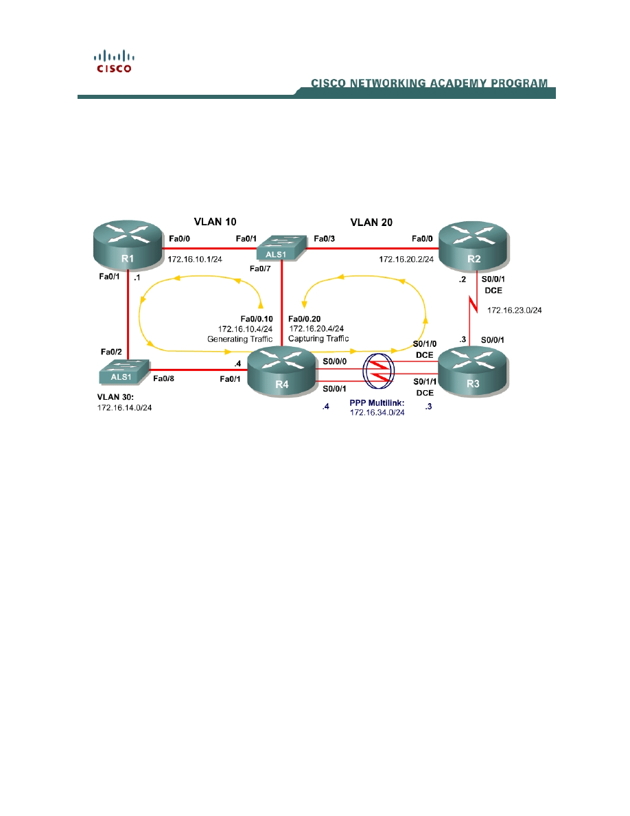
Topology Diagram
Scenario
In this lab, you will explore how traffic shaping interacts with traffic policing.
This lab will use the NQR tool from the Pagent toolset to observe delay and
jitter statistics as you implement your solutions. You will investigate how
different shaping and policing affect packet delay. If you have extra time to
complete this lab, do not hesitate to extend this scenario to more configurations
than simply those given here.
Typically, commands and command output will only be shown if they have not
been implemented in preceding Module 4 labs, so it is highly recommended that
you complete Labs 4.1 through 4.7 to ensure knowledge of the queuing,
shaping, and policing strategies and their configurations.
Preparation
This lab relies on the Advanced Pagent Configuration which you should have
created in Lab 3.1: Preparing for QoS.
Prior to beginning this lab, configure R4 and the switch according to the
Advanced Pagent Configuration. You may easily accomplish this on R4 by

loading the advanced-ios.cfg file from flash memory into the NVRAM, and
reloading.
R4# copy flash:advanced-ios.cfg startup-config
Destination filename [startup-config]?
[OK]
2875 bytes copied in 1.456 secs (1975 bytes/sec)
R4# reload
Proceed with reload? [confirm]
On the switch, load the advanced.cfg file into NVRAM and reload the device.
ALS1# copy flash:advanced.cfg startup-config
Destination filename [startup-config]?
[OK]
2875 bytes copied in 1.456 secs (1975 bytes/sec)
ALS1# reload
Proceed with reload? [confirm]
Unlike Labs 4.6 and 4.7, this lab will use the NQR tool in the Pagent toolset
rather than the TGN traffic generator. Do not load the TGN traffic generator
configuration.
Step 1: Configure Physical Interfaces and Routing
1. Configure all IP addresses shown in the diagram and use a clockrate of
800 kbps on all serial links. On the serial interfaces, set the informational
bandwidth appropriately.
2. Bind the serial links between R3 and R4 in a PPP multilink. Do not
configure Link Fragmentation and Interleaving (LFI) on the multilink
interface.
3. Configure OSPF to route for all networks shown in the diagram.
4. Make sure that the outbound queuing method for R3’s serial interface
facing R2 is WFQ.
Step 2: Configure NQR on R4
The NQR tool in the Pagent toolset can assist network administrators in
discovering delay and jitter statistics for traffic traversing their network. Enter
NQR configuration mode by issuing the nqr command from the privilege EXEC
prompt.
Copy and paste the configuration shown below into NQR on R4. This
configuration will simulate two traffic streams: a constant high-bandwidth stream
and a bursty, lower-bandwidth stream concurrent with it. Please see appendix
A for the NETLAB compatible version.
2 - 7
CCNP: Optimizing Converged Networks v5.0 - Lab 4-8
Copyright
© 2007, Cisco Systems, Inc

fastethernet0/0
add tcp
send 2000
rate 150
length random 200 to 1000
datalink ios-dependent fastethernet0/0.10
l2-arp-for 172.16.10.1
l3-src 172.16.10.4
l3-dest 172.16.20.4
l4-dest 21
fastethernet0/0.20 ios-dependent capture
add clone-of 1
l4-dest 23
send 500
rate 100
burst on
burst duration on 1000
burst duration off 3000
The NQR configuration here sends a controlled amount of packets—2000 for
the larger stream, 500 for the smaller stream—and will stop when all packets
are sent.
To begin NQR testing, issue either the start send command in NQR
configuration mode or the nqr start send command from privileged EXEC
mode. Time will pass, and then the router will inform you when all packets have
been sent. There is no need to stop the streams since they will stop on their
own.
Finally, issue the show pkt-seq-drop-stats, show delay, and show jitter NQR
commands to display drop/resequencing, delay, and jitter statistics,
respectively. Example output is shown below, although this type of output will
not be shown again later in the lab. Record all statistics by copying and pasting
them into a text editor such as Notepad. Record a baseline reading for your
current topology.
R4(NQR:OFF,Fa0/0:2/2)# start send
R4(NQR:SEND,Fa0/0:2/2)#
Send process complete.
R4(NQR:WAIT,Fa0/0:2/2)#
R4(NQR:OFF,Fa0/0:2/2)# show pkt-seq-drop-stats
Summary of packet sequence/drop stats of traffic streams
ts# template interface sent recvd dropped out-of-seq max-seq
1 TCP Fa0/0.10* 2000 1919 81 37 568
2 TCP Fa0/0.10* 500 500 0 0 500
R4(NQR:OFF,Fa0/0:2/2)# show delay-stats
Summary of delay-stats of traffic streams
ts# template interface min-delay max-delay avg-delay stdev-delay
1 TCP Fa0/0.10* 0.004364 0.580043 0.238835 0.143506
2 TCP Fa0/0.10* 0.004390 0.273886 0.098115 0.077852
R4(NQR:OFF,Fa0/0:2/2)# show jitter-stats
3 - 7
CCNP: Optimizing Converged Networks v5.0 - Lab 4-8
Copyright
© 2007, Cisco Systems, Inc

Summary of jitter-stats of traffic streams
ts# template interface min-jitter max-jitter avg-jitter stdev-jitter
1 TCP Fa0/0.10* 0.000033 0.367644 0.116765 0.083715
2 TCP Fa0/0.10* 0.000370 0.156045 0.066655 0.040675
Notice that packets are even dropped when no policing or shaping is configured
because congestion occurred with only default queuing tools in place.
Step 3: Configure Traffic Policing
On R3, police egress traffic toward R2 to a rate of 700 kbps. Configure this
either on a per-interface basis or using a policy-map to police the default class.
Then, run the NQR test again and record and compare statistics with the
baseline statistics you captured in Step 2.
Run NQR again, record all statistics, and then compare NQR statistics.
How did these packet drop statistics compare to the earlier ones?
Identify where packet drops occurred in the topology using the show interfaces
command.
Step 4: Configure Traffic Shaping
Configure R4 to shape traffic exiting the multilink interface. Shape the traffic
down to the same rate that you are using to police traffic on R3. Use either the
class-based method by shaping the default class or using the Generic Traffic
Shaping on the multilink interface.
Run NQR again, record all statistics, and then compare NQR statistics.
How would shaping engender fewer packet drops even if the policing rate was
not changed?
To what real-life scenario is this situation similar?
Final Configurations
R1# show run
4 - 7
CCNP: Optimizing Converged Networks v5.0 - Lab 4-8
Copyright
© 2007, Cisco Systems, Inc

!
hostname R1
!
interface FastEthernet0/0
ip address 172.16.10.1 255.255.255.0
no shutdown
!
interface FastEthernet0/1
ip address 172.16.14.1 255.255.255.0
no shutdown
!
router ospf 1
network 172.16.0.0 0.0.255.255 area 0
!
end
R2# show run
!
hostname R2
!
interface FastEthernet0/0
ip address 172.16.20.2 255.255.255.0
no shutdown
!
interface Serial0/0/1
ip address 172.16.23.2 255.255.255.0
clock rate 800000
no shutdown
!
router ospf 1
network 172.16.0.0 0.0.255.255 area 0
!
end
R3# show run
!
hostname R3
!
policy-map mypolicy
class class-default
police 700000
!
interface Multilink1
ip address 172.16.34.3 255.255.255.0
ppp multilink
ppp multilink group 1
!
interface Serial0/0/1
ip address 172.16.23.3 255.255.255.0
service-policy output mypolicy
no shutdown
!
interface Serial0/1/0
bandwidth 800
no ip address
encapsulation ppp
clock rate 800000
ppp multilink
ppp multilink group 1
no shutdown
!
interface Serial0/1/1
bandwidth 800
5 - 7
CCNP: Optimizing Converged Networks v5.0 - Lab 4-8
Copyright
© 2007, Cisco Systems, Inc

no ip address
encapsulation ppp
clock rate 800000
ppp multilink
ppp multilink group 1
no shutdown
!
router ospf 1
network 172.16.0.0 0.0.255.255 area 0
!
end
R4# show run
!
hostname R4
!
policy-map mypolicy
class class-default
shape peak 700000
!
interface Multilink1
ip address 172.16.34.4 255.255.255.0
ppp multilink
ppp multilink group 1
service-policy output mypolicy
!
interface FastEthernet0/1
ip address 172.16.14.4 255.255.255.0
no shutdown
!
interface Serial0/0/0
bandwidth 800
ip address 172.16.34.4 255.255.255.0
encapsulation ppp
ppp multilink
ppp multilink group 1
no shutdown
!
interface Serial0/0/1
bandwidth 800
no ip address
encapsulation ppp
ppp multilink
ppp multilink group 1
no shutdown
!
router ospf 1
network 172.16.0.0 0.0.255.255 area 0
!
end
Appendix A: NetLab-compatible NQR Configuration
NQR Configuration on R4
fastethernet0/0
add tcp
send 2000
rate 150
length random 200 to 1000
l2-dest $R1 Fa0/0’s MAC$
6 - 7
CCNP: Optimizing Converged Networks v5.0 - Lab 4-8
Copyright
© 2007, Cisco Systems, Inc

l3-src 172.16.10.4
l3-dest 172.16.20.4
l4-dest 21
fastethernet0/0 capture
add clone-of 1
l4-dest 23
send 500
rate 100
burst on
burst duration on 1000
burst duration off 3000
7 - 7
CCNP: Optimizing Converged Networks v5.0 - Lab 4-8
Copyright
© 2007, Cisco Systems, Inc
Wyszukiwarka
Podobne podstrony:
CCNP4 lab 6 4 en
CCNP4 lab 4 9 en
CCNP4 lab 3 1 en
CCNP4 lab 4 7 en
CCNP4 lab 3 2 en
CCNP4 lab 3 3 en
CCNP4 lab 4 2 en
CCNP4 lab 4 6 en
CCNP4 lab 5 1 en
CCNP4 lab 2 1 en
CCNP4 lab 4 4 en
CCNP4 lab 4 3 en
CCNP4 lab 6 3 en
CCNP4 lab 4 5 en
CCNP4 lab 4 1 en
CCNP4 lab 6 5 en
CCNP4 lab 6 5 en
CCNP4 lab 6 1b en
CCNP4 lab 6 2b en
więcej podobnych podstron