1 - 13
CCNP: Building Multilayer Switched Networks v5.0 - Lab 4-2
Copyright
© 2006, Cisco Systems, Inc
Lab 4-2 Inter-VLAN Routing with an Internal Route Processor and
Monitoring CEF Functions
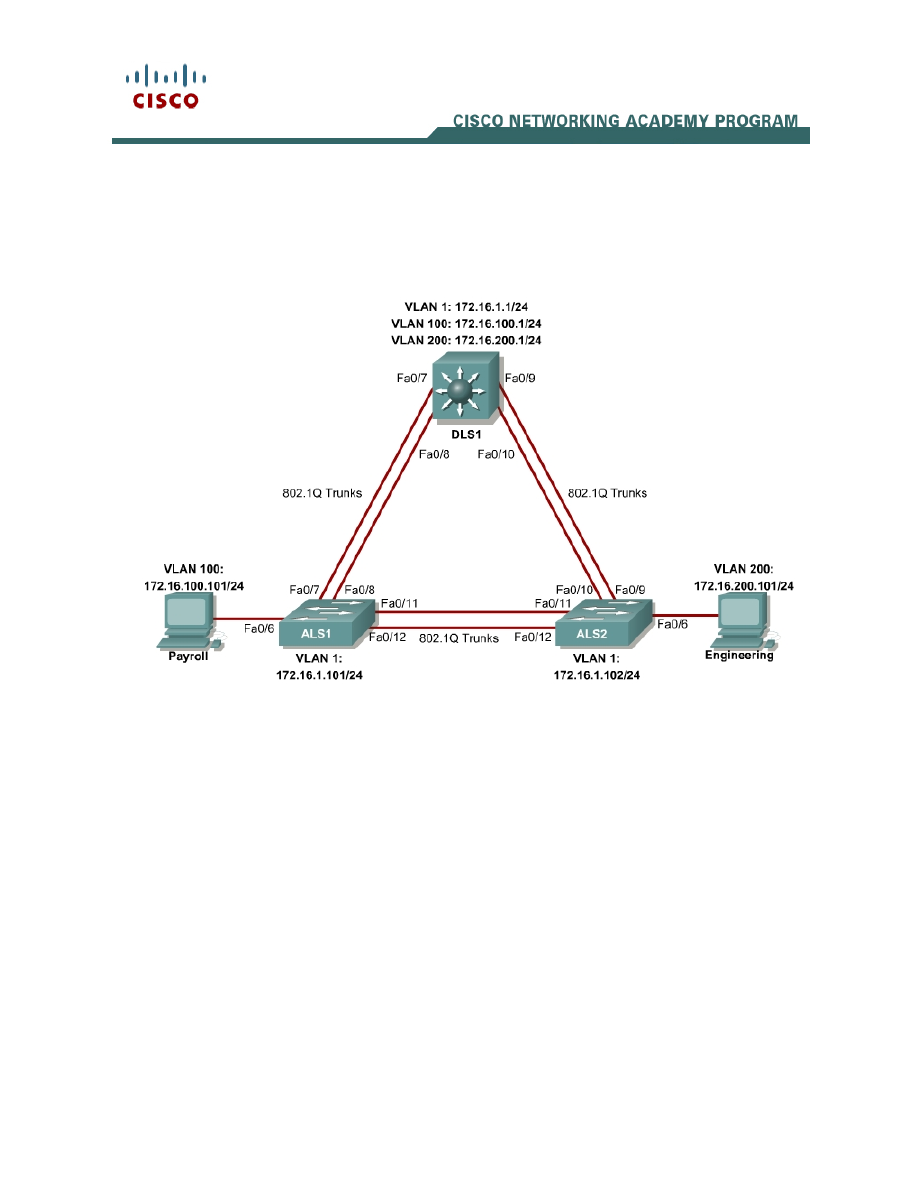
Topology Diagram
Objective
This lab routes between VLANs using a 3560 switch with an internal route
processor using Cisco Express Forwarding (CEF).
Scenario
The current network equipment includes a 3560 distribution layer switch and
two 2960 access layer switches. The network is segmented into three functional
subnets using VLANs for better network management. The VLANs include
Finance, Engineering, and a subnet for equipment management, which is the
default management VLAN, VLAN 1. After VTP and trunking have been
configured for the switches, Switched Virtual Interfaces (SVI) are used on the
distribution layer switch to route between these VLANs, giving full connectivity
to the internal network.

2 - 13
CCNP: Building Multilayer Switched Networks v5.0 - Lab 4-2
Copyright
© 2006, Cisco Systems, Inc
Step 1
Power up the switches and use the standard process for establishing a
HyperTerminal console connection from a workstation to each switch in your
pod. If you are remotely accessing your equipment, follow your teacher’s
instructions.
Remove all VLAN information and configurations that were previously entered
into your switches. (Refer to Lab 2.0a or 2.0b if needed.)
Step 2
Cable the lab according to the diagram. Configure the hostname, password,
and telnet access on each switch.
The following is a sample configuration for the 2960 switch ALS1:
Switch# configure terminal
Enter configuration commands, one per line. End with CNTL/Z.
Switch(config)# hostname ALS1
ALS1(config)# enable secret cisco
ALS1(config)# line vty 0 15
ALS1(config-line)# password cisco
ALS1(config-line)# login
ALS1(config-line)# end
The following is a sample configuration for the 2960 switch ALS2:
Switch# configure terminal
Enter configuration commands, one per line. End with CNTL/Z.
Switch(config)# hostname ALS2
ALS2(config)# enable secret cisco
ALS2(config)# line vty 0 15
ALS2(config-line)# password cisco
ALS2(config-line)# login
ALS2(config-line)# end
The following is a sample configuration for the 3560 switch DLS1:
Switch# configure terminal
Enter configuration commands, one per line. End with CNTL/Z.
Switch(config)# hostname DLS1
DLS1(config)# enable secret cisco
DLS1(config)# line vty 0 15
DLS1(config-line)#password cisco
DLS1(config-line)# login
DLS1(config-line)# end
Configure management IP addresses on VLAN 1 for all three switches
according to the diagram.
The following is a sample configuration for the 2960 switch ALS1:
ALS1# configure terminal
Enter configuration commands, one per line. End with CNTL/Z.
ALS1(config)# interface vlan 1

3 - 13
CCNP: Building Multilayer Switched Networks v5.0 - Lab 4-2
Copyright
© 2006, Cisco Systems, Inc
ALS1(config-if)# ip address 172.16.1.101 255.255.255.0
ALS1(config-if)# no shutdown
ALS1(config-if)# exit
The following is a sample configuration for the 2960 switch ALS2:
ALS2# configure terminal
Enter configuration commands, one per line. End with CNTL/Z.
ALS2(config)# interface vlan 1
ALS2(config-if)# ip address 172.16.1.102 255.255.255.0
ALS2(config-if)# no shutdown
ALS2(config-if)# exit
The following is a sample configuration for the 3560 switch DLS1:
DLS1# configure terminal
Enter configuration commands, one per line. End with CNTL/Z.
DLS1(config)# interface vlan 1
DLS1(config-if)# ip address 172.16.1.1 255.255.255.0
DLS1(config-if)# no shutdown
DLS1(config-if)# exit
Configure default gateways on the access layer switches. The distribution layer
switch will not use a default gateway, because it acts as a Layer 3 device. The
access layer switches act as Layer 2 devices and need a default gateway to
send traffic off of the local subnet for the management VLAN.
The following is a sample configuration for the 2960 switch ALS1:
ALS1# configure terminal
Enter configuration commands, one per line. End with CNTL/Z.
ALS1(config)# ip default-gateway 172.16.1.1
ALS1(config-line)# end
The following is a sample configuration for the 2960 switch ALS2:
ALS2# configure terminal
Enter configuration commands, one per line. End with CNTL/Z.
ALS2(config)# ip default-gateway 172.16.1.1
ALS2(config-line)# end
Step 3
Configure trunks and EtherChannels between switches.
To distribute VLAN and VTP information between the switches, trunks are
needed between the three switches. Configure these trunks according to the
diagram. EtherChannel is used for these trunks. EtherChannel allows you to
utilize both Fast Ethernet interfaces that are available between each device,
thereby doubling the bandwidth.
The following is a sample configuration for the trunks and EtherChannel from
DLS1 to ASL1. The switchport trunk encapsulation [isl | dot1q] command is
used because this switch also supports ISL encapsulation.

4 - 13
CCNP: Building Multilayer Switched Networks v5.0 - Lab 4-2
Copyright
© 2006, Cisco Systems, Inc
DLS1# configure terminal
Enter configuration commands, one per line. End with CNTL/Z.
DLS1(config)# interface range fastethernet 0/7 - 8
DLS1(config-if-range)# switchport trunk encapsulation dot1q
DLS1(config-if-range)# switchport mode trunk
DLS1(config-if-range)# channel-group 1 mode desirable
Creating a port-channel interface Port-channel 1
The following is a sample configuration for the trunks and EtherChannel from
DLS1 to ASL2:
DLS1# configure terminal
Enter configuration commands, one per line. End with CNTL/Z.
DLS1(config)# interface range fastethernet 0/9 - 10
DLS1(config-if-range)# switchport trunk encapsulation dot1q
DLS1(config-if-range)# switchport mode trunk
DLS1(config-if-range)# channel-group 2 mode desirable
Creating a port-channel interface Port-channel 2
The following is a sample configuration for the trunks and EtherChannel
between ALS1 and DLS1, and for the trunks and EtherChannel between ALS1
and ALS2:
ALS1# configure terminal
Enter configuration commands, one per line. End with CNTL/Z.
ALS1(config)# interface range fastethernet 0/11 - 12
ALS1(config-if-range)# switchport mode trunk
ALS1(config-if-range)# channel-group 1 mode desirable
Creating a port-channel interface Port-channel 1
ALS1(config-if-range)# exit
ALS1(config)# interface range fastethernet 0/7 - 8
ALS1(config-if-range)# switchport mode trunk
ALS1(config-if-range)# channel-group 2 mode desirable
Creating a port-channel interface Port-channel 2
The following is a sample configuration for the trunks and EtherChannel
between ALS2 and DLS1, and for the trunks and EtherChannel between ALS2
and ALS1.
ALS2# configure terminal
Enter configuration commands, one per line. End with CNTL/Z.
ALS2(config)# interface range fastethernet 0/11 - 12
ALS2(config-if-range)# switchport mode trunk
ALS2(config-if-range)# channel-group 1 mode desirable
Creating a port-channel interface Port-channel 1
ALS2(config-if-range)# exit
ALS1(config)# interface range fastethernet 0/7 - 8
ALS1(config-if-range)# switchport mode trunk
ALS1(config-if-range)# channel-group 2 mode desirable
Creating a port-channel interface Port-channel 2

5 - 13
CCNP: Building Multilayer Switched Networks v5.0 - Lab 4-2
Copyright
© 2006, Cisco Systems, Inc
Verify trunking between DLS1, ALS1, and ALS2 using the show interface
trunk command on all switches.
DLS1# show interface trunk
Port Mode Encapsulation Status Native vlan
Po1 on 802.1q trunking 1
Po2 on 802.1q trunking 1
Port Vlans allowed on trunk
Po1 1-4094
Po2 1-4094
Port Vlans allowed and active in management domain
Po1 1
Po2 1
Port Vlans in spanning tree forwarding state and not pruned
Po1 1
Po2 1
Use the show etherchannel summary command on each switch to verify the
EtherChannels.
The following is sample output from ALS1. Notice the two EtherChannels on the
access layer switches.
ALS1# show etherchannel summary
Flags: D - down P - in port-channel
I - stand-alone s - suspended
H - Hot-standby (LACP only)
R - Layer3 S - Layer2
U - in use f - failed to allocate aggregator
u - unsuitable for bundling
w - waiting to be aggregated
d - default port
Number of channel-groups in use: 2
Number of aggregators: 2
Group Port-channel Protocol Ports
------+-------------+-----------+---------------------------------------------
1 Po1(SU) PAgP Fa0/11(P) Fa0/12(P)
2 Po2(SU) PAgP Fa0/7(P) Fa0/8(P)
1. Which ports are used for channel group 2?
Step 4
Change the VTP mode of ALS1 and ALS2 to client.
ALS1# configure terminal
Enter configuration commands, one per line. End with CNTL/Z.

6 - 13
CCNP: Building Multilayer Switched Networks v5.0 - Lab 4-2
Copyright
© 2006, Cisco Systems, Inc
ALS1(config)# vtp mode client
Setting device to VTP CLIENT mode.
ALS1(config)# end
ALS2# configure terminal
Enter configuration commands, one per line. End with CNTL/Z.
ALS2(config)# vtp mode client
Setting device to VTP CLIENT mode.
ALS2(config)# end
Verify the VTP changes with the show vtp status command.
ALS2# show vtp status
VTP Version : 2
Configuration Revision : 0
Maximum VLANs supported locally : 1005
Number of existing VLANs : 5
VTP Operating Mode : Client
VTP Domain Name :
VTP Pruning Mode : Disabled
VTP V2 Mode : Disabled
VTP Traps Generation : Disabled
MD5 digest : 0xC8 0xAB 0x3C 0x3B 0xAB 0xDD 0x34 0xCF
Configuration last modified by 0.0.0.0 at 3-1-93 15:47:34
2. How many VLANs can be supported locally on the 2960 switch?
Step 5
Create the VTP domain on DLS1 and create VLANS 100 and 200 for the
domain.
DLS1# configure terminal
Enter configuration commands, one per line. End with CNTL/Z.
DLS1(config)# vtp domain SWPOD
DLS1(config)# vlan 100
DLS1(config-vlan)# name Finance
DLS1(config-vlan)# exit
DLS1(config)# vlan 200
DLS1(config-vlan)# name Engineering
DLS1(config-vlan)# end
Verify VTP information throughout the domain using the show vlan and show
vtp status commands.
3. How many existing VLANs are in the VTP domain?

7 - 13
CCNP: Building Multilayer Switched Networks v5.0 - Lab 4-2
Copyright
© 2006, Cisco Systems, Inc
Step 6
Configure the host ports for the appropriate VLANs according to the diagram.
ALS1# configure terminal
Enter configuration commands, one per line. End with CNTL/Z.
ALS1(config)# interface fastethernet 0/6
ALS1(config-if)# switchport mode access
ALS1(config-if)# switchport access vlan 100
ALS1(config-if)# end
ALS2# configure terminal
Enter configuration commands, one per line. End with CNTL/Z.
ALS2(config)# interface fastethernet 0/6
ALS2(config-if)# switchport mode access
ALS2(config-if)# switchport access vlan 200
ALS2(config-if)# end
4. Ping from the host on VLAN 100 to the host on VLAN 200. Was the ping
successful? Why do you think this is the case?
5. Ping from a host to the VLAN 1 management IP address of DLS1. Was the
ping successful? Why do you think this is the case?
Step 7
Create the Layer 3 VLAN interfaces to route between VLANs using the
interface vlan vlan-id command. You do not need to set up VLAN 1 because
this was done in Step 2.
The ip routing command is also needed to tell the switch that it acts as a Layer
3 device to route between these VLANs. Because the VLANs are all considered
directly connected, a routing protocol is not needed at this time.
DLS1# configure terminal
Enter configuration commands, one per line. End with CNTL/Z.
DLS1(config)# interface vlan 100
DLS1(config-if)# ip add 172.16.100.1 255.255.255.0
DLS1(config-if)# no shut
DLS1(config-if)# interface vlan 200
DLS1(config-if)# ip address 172.16.200.1 255.255.255.0
DLS1(config-if)# no shutdown
DLS1(config-if)# exit
DLS1(config)# ip routing
DLS1(config)# end
Verify the configuration using the show ip route command on DLS1.

8 - 13
CCNP: Building Multilayer Switched Networks v5.0 - Lab 4-2
Copyright
© 2006, Cisco Systems, Inc
DLS1# show ip route
Codes: C - connected, S - static, R - RIP, M - mobile, B - BGP
D - EIGRP, EX - EIGRP external, O - OSPF, IA - OSPF inter area
N1 - OSPF NSSA external type 1, N2 - OSPF NSSA external type 2
E1 - OSPF external type 1, E2 - OSPF external type 2, E - EGP
i - IS-IS, su - IS-IS summary, L1 - IS-IS level-1, L2 - IS-IS level-2
ia - IS-IS inter area, * - candidate default, U - per-user static route
o - ODR, P - periodic downloaded static route
Gateway of last resort is not set
172.16.0.0/24 is subnetted, 3 subnets
C 172.16.200.0 is directly connected, Vlan200
C 172.16.1.0 is directly connected, Vlan1
C 172.16.100.0 is directly connected, Vlan100
Step 8
Verify inter-VLAN routing by the internal route processor.
5. Ping from the Engineering host to the Finance host. Was the ping successful
this time?
6. Telnet from a host to the VLAN 1 IP address of DLS1. Can this switch be
remotely accessed from this host?
Example telnet from the Engineering host:
C:>telnet 172.16.1.1
User Access Verification
Password: <vty-password>
DLS1>
Step 9
Cisco Express Forwarding (CEF) implements an advanced IP lookup and
forwarding algorithm to deliver maximum Layer 3 switching performance. CEF
is less CPU-intensive than fast switching route caching.
In dynamic networks, fast switching cache entries are frequently invalidated
because of routing changes. This can cause traffic to be process-switched
using the routing table, instead of fast-switched using the route cache. CEF

9 - 13
CCNP: Building Multilayer Switched Networks v5.0 - Lab 4-2
Copyright
© 2006, Cisco Systems, Inc
uses the Forwarding Information Base (FIB) lookup table to perform destination-
based switching of IP packets.
CEF is enabled by default on the 3560 switch.
Use the show ip cef command to display the status of CEF.
DLS1# show ip cef
Prefix Next Hop Interface
0.0.0.0/32 receive
172.16.1.0/24 attached Vlan1
172.16.1.0/32 receive
172.16.1.1/32 receive
172.16.1.101/32 attached Vlan1
172.16.1.102/32 attached Vlan1
172.16.1.255/32 receive
172.16.100.0/24 attached Vlan100
172.16.100.0/32 receive
172.16.100.1/32 receive
172.16.100.255/32 receive
172.16.200.0/24 attached Vlan200
172.16.200.0/32 receive
172.16.200.1/32 receive
172.16.200.255/32 receive
224.0.0.0/4 drop
224.0.0.0/24 receive
255.255.255.255/32 receive
Use the show ip interface command to verify that CEF is enabled on an
interface. The following output shows that CEF is enabled on VLAN 100.
DLS1# show ip interface vlan 100
Vlan100 is up, line protocol is up
Internet address is 172.16.100.1/24
Broadcast address is 255.255.255.255
Address determined by setup command
MTU is 1500 bytes
Helper address is not set
Directed broadcast forwarding is disabled
Outgoing access list is not set
Inbound access list is not set
Proxy ARP is enabled
Local Proxy ARP is disabled
Security level is default
Split horizon is enabled
ICMP redirects are always sent
ICMP unreachables are always sent
ICMP mask replies are never sent
IP fast switching is enabled
IP CEF switching is enabled
IP CEF switching turbo vector
IP multicast fast switching is disabled
IP multicast distributed fast switching is disabled
IP route-cache flags are Fast, CEF
Router Discovery is disabled
IP output packet accounting is disabled
IP access violation accounting is disabled
TCP/IP header compression is disabled
RTP/IP header compression is disabled
Probe proxy name replies are disabled

10 - 13
CCNP: Building Multilayer Switched Networks v5.0 - Lab 4-2
Copyright
© 2006, Cisco Systems, Inc
Policy routing is disabled
Network address translation is disabled
WCCP Redirect outbound is disabled
WCCP Redirect inbound is disabled
WCCP Redirect exclude is disabled
BGP Policy Mapping is disabled
Use the show ip cef summary command to display the CEF table summary.
The show ip cef detail command shows CEF operation in detail for the switch.
DLS1# show ip cef summary
IPv4 CEF is enabled for distributed and running
VRF Default:
18 prefixes (18/0 fwd/non-fwd)
Table id 0, 0 resets
Database epoch: 1 (18 entries at this epoch)
DLS1# show ip cef detail
IPv4 CEF is enabled for distributed and running
VRF Default:
18 prefixes (18/0 fwd/non-fwd)
Table id 0, 0 resets
Database epoch: 1 (18 entries at this epoch)
0.0.0.0/32, epoch 1, flags receive
Special source: receive
receive
172.16.1.0/24, epoch 1, flags attached, connected
attached to Vlan1
172.16.1.0/32, epoch 1, flags receive
receive
172.16.1.1/32, epoch 1, flags receive
receive
172.16.1.101/32, epoch 1
Adj source: IP adj out of Vlan1, addr 172.16.1.101
attached to Vlan1
172.16.1.102/32, epoch 1
Adj source: IP adj out of Vlan1, addr 172.16.1.102
attached to Vlan1
172.16.1.255/32, epoch 1, flags receive
receive
172.16.100.0/24, epoch 1, flags attached, connected
attached to Vlan100
172.16.100.0/32, epoch 1, flags receive
receive
172.16.100.1/32, epoch 1, flags receive
receive
172.16.100.255/32, epoch 1, flags receive
receive
172.16.200.0/24, epoch 1, flags attached, connected
attached to Vlan200
172.16.200.0/32, epoch 1, flags receive
receive
172.16.200.1/32, epoch 1, flags receive
receive
172.16.200.255/32, epoch 1, flags receive
receive
224.0.0.0/4, epoch 1
Special source: drop
drop
224.0.0.0/24, epoch 1, flags receive
Special source: receive

11 - 13
CCNP: Building Multilayer Switched Networks v5.0 - Lab 4-2
Copyright
© 2006, Cisco Systems, Inc
receive
255.255.255.255/32, epoch 1, flags receive
Special source: receive
receive
Final Configuration
DLS1# show run
!
hostname DLS1
!
enable secret cisco
!
interface Port-channel1
switchport trunk encapsulation dot1q
switchport mode trunk
!
interface Port-channel2
switchport trunk encapsulation dot1q
switchport mode trunk
!
interface FastEthernet0/7
switchport trunk encapsulation dot1q
switchport mode trunk
channel-group 1 mode desirable
!
interface FastEthernet0/8
switchport trunk encapsulation dot1q
switchport mode trunk
channel-group 1 mode desirable
!
interface FastEthernet0/9
switchport trunk encapsulation dot1q
switchport mode trunk
channel-group 2 mode desirable
!
interface FastEthernet0/10
switchport trunk encapsulation dot1q
switchport mode trunk
channel-group 2 mode desirable
!
interface Vlan1
ip address 172.16.1.1 255.255.255.0
no shutdown
!
interface Vlan100
ip address 172.16.100.1 255.255.255.0
no shutdown
!
interface Vlan200
ip address 172.16.200.1 255.255.255.0
no shutdown
!
line vty 0 4
password cisco
login
line vty 5 15
password cisco
login
!
end

12 - 13
CCNP: Building Multilayer Switched Networks v5.0 - Lab 4-2
Copyright
© 2006, Cisco Systems, Inc
ALS1# show run
!
hostname ALS1
!
enable secret cisco
!
interface Port-channel1
switchport mode trunk
!
interface Port-channel2
switchport mode trunk
!
interface FastEthernet0/6
switchport access vlan 100
switchport mode access
!
interface FastEthernet0/7
switchport mode trunk
channel-group 2 mode desirable
!
interface FastEthernet0/8
switchport mode trunk
channel-group 2 mode desirable
!
interface FastEthernet0/11
switchport mode trunk
channel-group 1 mode desirable
!
interface FastEthernet0/12
switchport mode trunk
channel-group 1 mode desirable
!
interface Vlan1
ip address 172.16.1.101 255.255.255.0
no shutdown
!
ip default-gateway 172.16.1.1
!
line vty 0 4
password cisco
login
line vty 5 15
password cisco
login
!
end
ALS2# show run
!
hostname ALS2
!
enable secret cisco
!
interface Port-channel1
switchport mode trunk
!
interface Port-channel2
switchport mode trunk
!
interface FastEthernet0/6

13 - 13
CCNP: Building Multilayer Switched Networks v5.0 - Lab 4-2
Copyright
© 2006, Cisco Systems, Inc
switchport access vlan 200
switchport mode access
!
interface FastEthernet0/9
switchport mode trunk
channel-group 2 mode desirable
!
interface FastEthernet0/10
switchport mode trunk
channel-group 2 mode desirable
!
interface FastEthernet0/11
switchport mode trunk
channel-group 1 mode desirable
!
interface FastEthernet0/12
switchport mode trunk
channel-group 1 mode desirable
!
interface Vlan1
ip address 172.16.1.102 255.255.255.0
no shutdown
!
ip default-gateway 172.16.1.1
!
line vty 0 4
password cisco
login
line vty 5 15
password cisco
login
!
end
Wyszukiwarka
Podobne podstrony:
CCNP3 lab 3 2 en
CCNP3 lab 2 0 b en
CCNP3 lab 4 1 en
CCNP3 lab 6 2 en
CCNP3 lab 8 1 en
CCNP3 lab 2 1 en
CCNP3 lab 5 1 en
CCNP3 lab 7 1 en
CCNP3 lab 6 3 en
CCNP3 lab 3 5 en
CCNP3 lab 3 1 en
CCNP3 lab 2 0 a en
CCNP3 lab 3 3 en
CCNP3 lab 3 4 en
CCNP3 lab 8 3 en
CCNP3 lab 8 2 en
CCNP3 lab 6 2 opt en
CCNP3 lab 6 1 opt en
NS2 lab 4 4 7 en Configure Cisco IOS IPSec using Pre Shared Keys
więcej podobnych podstron