1 - 12
CCNP: Building Multilayer Switched Networks v5.0 - Lab 3-4
Copyright
© 2006, Cisco Systems, Inc
Lab 3-4 Multiple Spanning Tree
Objective
The purpose of this lab is to observe the behavior of MST (multiple
spanning tree).
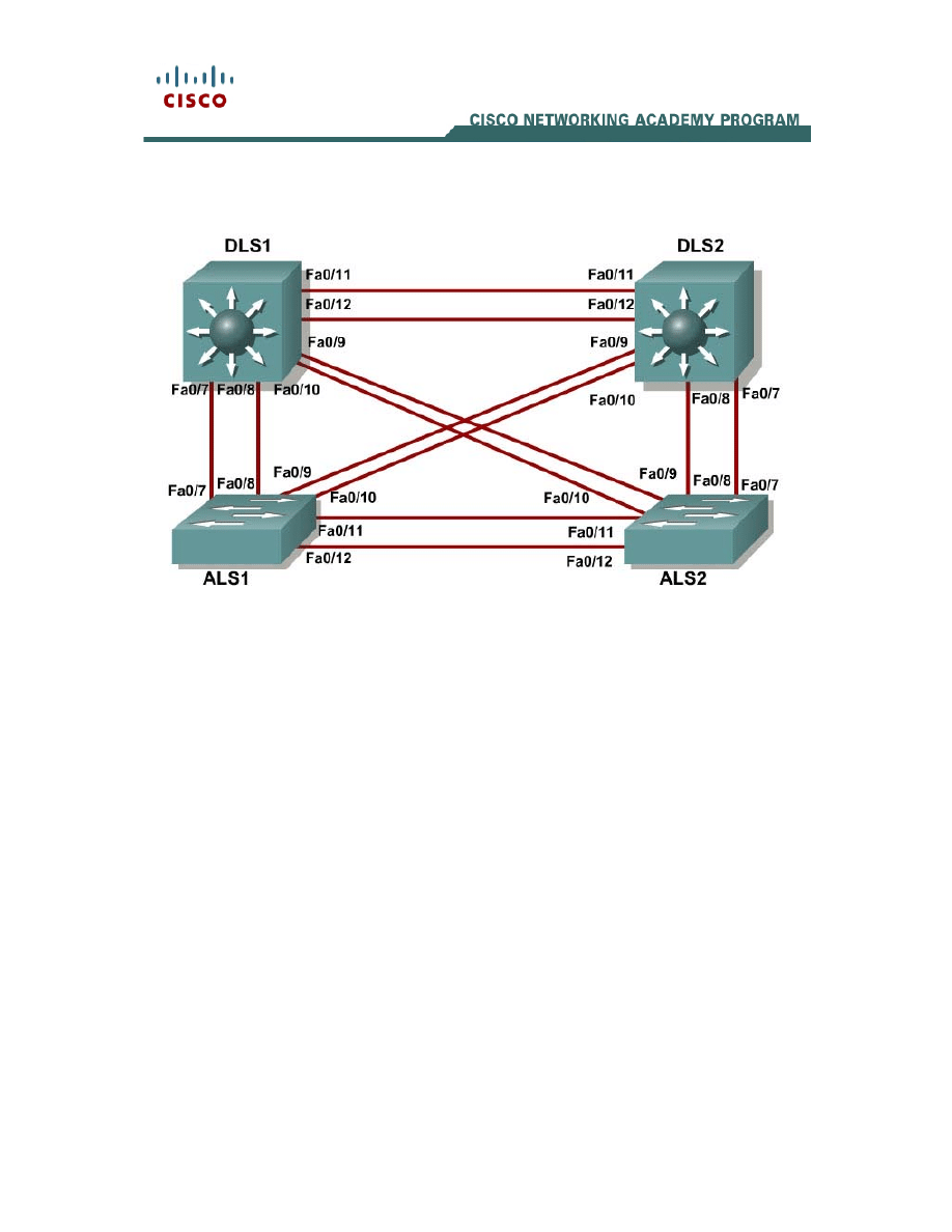
Scenario
Four switches have just been installed. The distribution layer switches are
Catalyst 3560s, and the access layer switches are Catalyst 2960s. There
are redundant uplinks between the access layer and distribution layer.
Because of the possibility of bridging loops, spanning tree logically
removes any redundant links. In this lab, we will group VLANs using MST
so that we can have less spanning tree instances running at once to save
switch CPU load.
Step 1
Start by deleting vlan.dat, erasing the startup configuration, and reloading
your switches. After reloading the switches, give them hostnames.
Configure ports f0/7 through f0/12 to be trunks. On the 3560s, you first
need to set the trunk encapsulation to dot1q. On the 2960s, only dot1q is
supported, so it does not need to be set, but the mode still needs to be
changed to trunk. If you do not set the mode of the ports to be trunk, the

2 - 12
CCNP: Building Multilayer Switched Networks v5.0 - Lab 3-4
Copyright
© 2006, Cisco Systems, Inc
links do not form trunks and remain access ports (default mode on a 3560
or 2960 is dynamic auto; default mode on a 3550 or 2950 is dynamic
desirable).
DLS1#configure terminal
Enter configuration commands, one per line. End with CNTL/Z.
DLS1(config)#interface range f0/7 - 12
DLS1(config-if-range)#switchport trunk encapsulation dot1q
DLS1(config-if-range)#switchport mode trunk
Step 2
Configure all switches with VTP mode transparent and VTP domain
CISCO. Add VLANs 10, 20, 30, 40, 50, 60, 70, 80, 90 and 100 to all of
them. Use the show vlan brief command to view the VLAN
configurations.
DLS1#configure terminal
Enter configuration commands, one per line. End with CNTL/Z.
DLS1(config)#vtp mode transparent
Setting device to VTP TRANSPARENT mode.
DLS1(config)#vtp domain CISCO
Changing VTP domain name from NULL to CISCO
DLS1(config)#vlan 10,20,30,40,50,60,70,80,90,100
DLS1(config-vlan)#end
DLS1#show vlan brief
00:11:56: %SYS-5-CONFIG_I: Configured from console by console
VLAN Name Status Ports
---- -------------------------------- --------- -------------------------------
1 default active Fa0/1, Fa0/2, Fa0/3, Fa0/4
Fa0/5, Fa0/6, Fa0/7, Fa0/8
Fa0/9, Fa0/10, Fa0/11, Fa0/12
Fa0/13, Fa0/14, Fa0/15, Fa0/16
Fa0/17, Fa0/18, Fa0/19, Fa0/20
Fa0/21, Fa0/22, Fa0/23, Fa0/24
Gi0/1, Gi0/2
10 VLAN0010 active
20 VLAN0020 active
30 VLAN0030 active
40 VLAN0040 active
50 VLAN0050 active
60 VLAN0060 active
70 VLAN0070 active
80 VLAN0080 active
90 VLAN0090 active
100 VLAN0100 active
1002 fddi-default act/unsup
1003 token-ring-default act/unsup
1004 fddinet-default act/unsup
1005 trnet-default act/unsup
Step 3
If you issue the show spanning-tree command on one of the switches,
you see 11 spanning tree instances running.
DLS1#show spanning-tree
VLAN0001
Spanning tree enabled protocol ieee
Root ID Priority 32769
Address 000a.b8a9.d680
Cost 19

3 - 12
CCNP: Building Multilayer Switched Networks v5.0 - Lab 3-4
Copyright
© 2006, Cisco Systems, Inc
Port 13 (FastEthernet0/11)
Hello Time 2 sec Max Age 20 sec Forward Delay 15 sec
Bridge ID Priority 32769 (priority 32768 sys-id-ext 1)
Address 000a.b8a9.d780
Hello Time 2 sec Max Age 20 sec Forward Delay 15 sec
Aging Time 300
Interface Role Sts Cost Prio.Nbr Type
---------------- ---- --- --------- -------- ----------------------------
Fa0/7 Desg FWD 19 128.9 P2p
Fa0/8 Desg FWD 19 128.10 P2p
Fa0/9 Desg FWD 19 128.11 P2p
Fa0/10 Desg FWD 19 128.12 P2p
Fa0/11 Root FWD 19 128.13 P2p
Fa0/12 Altn BLK 19 128.14 P2p
VLAN0010
Spanning tree enabled protocol ieee
Root ID Priority 32778
Address 000a.b8a9.d680
Cost 19
Port 13 (FastEthernet0/11)
Hello Time 2 sec Max Age 20 sec Forward Delay 15 sec
Bridge ID Priority 32778 (priority 32768 sys-id-ext 10)
Address 000a.b8a9.d780
Hello Time 2 sec Max Age 20 sec Forward Delay 15 sec
Aging Time 300
Interface Role Sts Cost Prio.Nbr Type
---------------- ---- --- --------- -------- ----------------------------
Fa0/7 Desg FWD 19 128.9 P2p
Fa0/8 Desg FWD 19 128.10 P2p
Fa0/9 Desg FWD 19 128.11 P2p
Fa0/10 Desg FWD 19 128.12 P2p
Fa0/11 Root FWD 19 128.13 P2p
Fa0/12 Altn BLK 19 128.14 P2p
VLAN0020
Spanning tree enabled protocol ieee
Root ID Priority 32788
Address 000a.b8a9.d680
Cost 19
Port 13 (FastEthernet0/11)
Hello Time 2 sec Max Age 20 sec Forward Delay 15 sec
Bridge ID Priority 32788 (priority 32768 sys-id-ext 20)
Address 000a.b8a9.d780
Hello Time 2 sec Max Age 20 sec Forward Delay 15 sec
Aging Time 300
Interface Role Sts Cost Prio.Nbr Type
---------------- ---- --- --------- -------- ----------------------------
Fa0/7 Desg FWD 19 128.9 P2p
Fa0/8 Desg FWD 19 128.10 P2p
Fa0/9 Desg FWD 19 128.11 P2p
Fa0/10 Desg FWD 19 128.12 P2p
Fa0/11 Root FWD 19 128.13 P2p
Fa0/12 Altn BLK 19 128.14 P2p

4 - 12
CCNP: Building Multilayer Switched Networks v5.0 - Lab 3-4
Copyright
© 2006, Cisco Systems, Inc
<output omitted>
VLAN0090
Spanning tree enabled protocol ieee
Root ID Priority 32858
Address 000a.b8a9.d680
Cost 19
Port 13 (FastEthernet0/11)
Hello Time 2 sec Max Age 20 sec Forward Delay 15 sec
Bridge ID Priority 32858 (priority 32768 sys-id-ext 90)
Address 000a.b8a9.d780
Hello Time 2 sec Max Age 20 sec Forward Delay 15 sec
Aging Time 300
Interface Role Sts Cost Prio.Nbr Type
---------------- ---- --- --------- -------- ----------------------------
Fa0/7 Desg FWD 19 128.9 P2p
Fa0/8 Desg FWD 19 128.10 P2p
Fa0/9 Desg FWD 19 128.11 P2p
Fa0/10 Desg FWD 19 128.12 P2p
Fa0/11 Root FWD 19 128.13 P2p
Fa0/12 Altn BLK 19 128.14 P2p
VLAN0100
Spanning tree enabled protocol ieee
Root ID Priority 32868
Address 000a.b8a9.d680
Cost 19
Port 13 (FastEthernet0/11)
Hello Time 2 sec Max Age 20 sec Forward Delay 15 sec
Bridge ID Priority 32868 (priority 32768 sys-id-ext 100)
Address 000a.b8a9.d780
Hello Time 2 sec Max Age 20 sec Forward Delay 15 sec
Aging Time 300
Interface Role Sts Cost Prio.Nbr Type
---------------- ---- --- --------- -------- ----------------------------
Fa0/7 Desg FWD 19 128.9 P2p
Fa0/8 Desg FWD 19 128.10 P2p
Fa0/9 Desg FWD 19 128.11 P2p
Fa0/10 Desg FWD 19 128.12 P2p
Fa0/11 Root FWD 19 128.13 P2p
Fa0/12 Altn BLK 19 128.14 P2p
Spanning tree is running a separate spanning tree instance for each VLAN
we created, plus VLAN 1. This method assumes that each VLAN could be
running on a differently shaped topology. However, in many networks,
multiple VLANs follow the same physical topology, so multiple spanning-
tree calculations for the same topologies can get redundant. MST (multiple
spanning tree) lets you configure different spanning tree instances. Each
instance can hold a group of VLANs and gets its own spanning tree
calculation.
MST is convenient in that it is backward compatible with PVST. Two
switches only run MST with each other if they are in the same MST region.
An MST region is defined by switches having identical region names,

5 - 12
CCNP: Building Multilayer Switched Networks v5.0 - Lab 3-4
Copyright
© 2006, Cisco Systems, Inc
revision numbers, and VLAN-to-instance assignments. If they differ by any
single attribute, they are considered different MST regions and fall back to
PVST.
Step 4
To configure MST, first use the global configuration command spanning-
tree mode mst on all four switches.
DLS1(config)#spanning-tree mode mst
By default, all VLANs are assigned to instance 0, but can be moved
around to different instances when MST is configured. Issue the show
spanning-tree command and observe that there is only one spanning tree
(instance 0) coming up. Also notice that the mode is listed as MSTP.
DLS1#show spanning-tree
MST00
Spanning tree enabled protocol mstp
Root ID Priority 32768
Address 000a.b8a9.d680
Cost 0
Port 13 (FastEthernet0/11)
Hello Time 2 sec Max Age 20 sec Forward Delay 15 sec
Bridge ID Priority 32768 (priority 32768 sys-id-ext 0)
Address 000a.b8a9.d780
Hello Time 2 sec Max Age 20 sec Forward Delay 15 sec
Interface Role Sts Cost Prio.Nbr Type
---------------- ---- --- --------- -------- ----------------------------
Fa0/7 Desg FWD 200000 128.9 P2p
Fa0/8 Desg BLK 200000 128.10 P2p
Fa0/9 Desg FWD 200000 128.11 P2p
Fa0/10 Desg FWD 200000 128.12 P2p
Fa0/11 Root FWD 200000 128.13 P2p
Fa0/12 Altn BLK 200000 128.14 P2p
If you use the show spanning-tree mst configuration command, you
can see a switch’s current MST configuration. Because you have not
configured any MST region settings, the switch shows the default settings.
DLS1#show spanning-tree mst configuration
Name []
Revision 0
Instance Vlans mapped
-------- ---------------------------------------------------------------
0 1-4094
-------------------------------------------------------------------------
Step 5
Now that MST has been enabled, we can configure the MST region
settings to group VLANs. We use the region name CISCO and a revision
number of 1. We put VLANs 20 through 50 into instance 1, and 80 and
100 into instance 2. The rest of the VLANs remain in instance 0, the

6 - 12
CCNP: Building Multilayer Switched Networks v5.0 - Lab 3-4
Copyright
© 2006, Cisco Systems, Inc
default. To begin modifying the MST configuration, type the global
configuration command spanning-tree mst configuration. Configuring
MST is different from other switch configurations, because changes are
not applied until you are done, and you can abort changes if you want to.
Note: You must apply identical configurations on each switch for MST to
work properly.
DLS1#configure terminal
Enter configuration commands, one per line. End with CNTL/Z.
DLS1(config)#spanning-tree mst configuration
DLS1(config-mst)#
When you are in MST configuration mode, you can view the current
configuration using the show current command. You do not need to leave
configuration mode to execute this command. Notice that the output is
identical to show spanning-tree mst configuration.
DLS1(config-mst)#show current
Current MST configuration
Name []
Revision 0
Instance Vlans mapped
-------- ---------------------------------------------------------------
0 1-4094
-------------------------------------------------------------------------
Change the region name by typing name name. Change the revision
number by typing revision number.
DLS1(config-mst)#name CISCO
DLS1(config-mst)#revision 1
The last configuration change you have to make is putting VLANs into
instances. Use the command instance number vlan vlan_range. The
instance number can be between 0 and 15. Remember that 0 is the
default instance number.
DLS1(config-mst)# instance 1 vlan 20-50
DLS1(config-mst)# instance 2 vlan 80, 100
You can verify the changes you are about to make with the show
pending command. Remember that the changes that you just entered are
not committed until you type exit. If you do not like the changes you made,
you can leave the prompt without committing them by typing abort. In the
output below, notice the difference between show current and show
pending.
DLS1(config-mst)#show current
Current MST configuration
Name []
Revision 0
Instance Vlans mapped
-------- ---------------------------------------------------------------
0 1-4094

7 - 12
CCNP: Building Multilayer Switched Networks v5.0 - Lab 3-4
Copyright
© 2006, Cisco Systems, Inc
-------------------------------------------------------------------------
DLS1(config-mst)#show pending
Pending MST configuration
Name [CISCO]
Revision 1
Instance Vlans mapped
-------- ---------------------------------------------------------------
0 1-19,51-79,81-99,101-4094
1 20-50
2 80,100
-------------------------------------------------------------------------
DLS1(config-mst)#exit
If you enter the show spanning-tree mst configuration command, you
can see that the current configuration reflects the changes you just
committed. Remember to perform the same configuration on all four
switches.
DLS1#show span mst configuration
Name [CISCO]
Revision 1
Instance Vlans mapped
-------- ---------------------------------------------------------------
0 1-19,51-79,81-99,101-4094
1 20-50
2 80,100
-------------------------------------------------------------------------
Why do the switches wait until you are finished making changes to MST to
commit them, rather that changing MST as you enter commands (like
most switch commands)?
Verify that you have separate instances of spanning tree running for each
MST instance:
DLS1#show spanning-tree
MST00
Spanning tree enabled protocol mstp
Root ID Priority 32768
Address 000a.b8a9.d680
Cost 0
Port 13 (FastEthernet0/11)
Hello Time 2 sec Max Age 20 sec Forward Delay 15 sec
Bridge ID Priority 32768 (priority 32768 sys-id-ext 0)
Address 000a.b8a9.d780
Hello Time 2 sec Max Age 20 sec Forward Delay 15 sec
Interface Role Sts Cost Prio.Nbr Type
---------------- ---- --- --------- -------- ----------------------------
Fa0/7 Desg FWD 200000 128.9 P2p
Fa0/8 Desg FWD 200000 128.10 P2p
Fa0/9 Desg FWD 200000 128.11 P2p
Fa0/10 Desg FWD 200000 128.12 P2p

8 - 12
CCNP: Building Multilayer Switched Networks v5.0 - Lab 3-4
Copyright
© 2006, Cisco Systems, Inc
Fa0/11 Root FWD 200000 128.13 P2p
Fa0/12 Altn BLK 200000 128.14 P2p
MST01
Spanning tree enabled protocol mstp
Root ID Priority 32769
Address 000a.b8a9.d680
Cost 200000
Port 13 (FastEthernet0/11)
Hello Time 2 sec Max Age 20 sec Forward Delay 15 sec
Bridge ID Priority 32769 (priority 32768 sys-id-ext 1)
Address 000a.b8a9.d780
Hello Time 2 sec Max Age 20 sec Forward Delay 15 sec
Interface Role Sts Cost Prio.Nbr Type
---------------- ---- --- --------- -------- ----------------------------
Fa0/7 Desg FWD 200000 128.9 P2p
Fa0/8 Desg FWD 200000 128.10 P2p
Fa0/9 Desg FWD 200000 128.11 P2p
Fa0/10 Desg FWD 200000 128.12 P2p
Fa0/11 Root FWD 200000 128.13 P2p
Fa0/12 Altn BLK 200000 128.14 P2p
MST02
Spanning tree enabled protocol mstp
Root ID Priority 32770
Address 000a.b8a9.d680
Cost 200000
Port 13 (FastEthernet0/11)
Hello Time 2 sec Max Age 20 sec Forward Delay 15 sec
Bridge ID Priority 32770 (priority 32768 sys-id-ext 2)
Address 000a.b8a9.d780
Hello Time 2 sec Max Age 20 sec Forward Delay 15 sec
Interface Role Sts Cost Prio.Nbr Type
---------------- ---- --- --------- -------- ----------------------------
Fa0/7 Desg FWD 200000 128.9 P2p
Fa0/8 Desg FWD 200000 128.10 P2p
Fa0/9 Desg FWD 200000 128.11 P2p
Fa0/10 Desg FWD 200000 128.12 P2p
Fa0/11 Root FWD 200000 128.13 P2p
Fa0/12 Altn BLK 200000 128.14 P2p
Challenge
You can modify per-instance MST spanning tree attributes the same way
you can modify per-VLAN attributes. Make DLS1 the root of instance 1
and DLS2 the root of instance 2.
HINT: Use a question mark on the global configuration command
spanning-tree mst ?.

9 - 12
CCNP: Building Multilayer Switched Networks v5.0 - Lab 3-4
Copyright
© 2006, Cisco Systems, Inc
END OF LAB FINAL CONFIGS:
DLS1#show running-config
!
hostname DLS1
!
!
vtp domain CISCO
vtp mode transparent
!
!
!
!
!
spanning-tree mst configuration
name CISCO
revision 1
instance 1 vlan 20-50
instance 2 vlan 80, 100
!
spanning-tree mst 1 priority 24576
!
!
vlan 10,20,30,40,50,60,70,80,90,100
!
!
interface FastEthernet0/7
switchport trunk encapsulation dot1q
switchport mode trunk
!
interface FastEthernet0/8
switchport trunk encapsulation dot1q
switchport mode trunk
!
interface FastEthernet0/9
switchport trunk encapsulation dot1q
switchport mode trunk
!
interface FastEthernet0/10
switchport trunk encapsulation dot1q
switchport mode trunk
!
interface FastEthernet0/11
switchport trunk encapsulation dot1q
switchport mode trunk
!
interface FastEthernet0/12
switchport trunk encapsulation dot1q
switchport mode trunk
!
!
end
DLS2#show running-config
!
hostname DLS2

10 - 12
CCNP: Building Multilayer Switched Networks v5.0 - Lab 3-4
Copyright
© 2006, Cisco Systems, Inc
!
!
vtp domain CISCO
vtp mode transparent
!
!
spanning-tree mode mst
!
spanning-tree mst configuration
name CISCO
revision 1
instance 1 vlan 20-50
instance 2 vlan 80, 100
!
spanning-tree mst 2 priority 24576
!
!
vlan 10,20,30,40,50,60,70,80,90,100
!
!
!
interface FastEthernet0/7
switchport trunk encapsulation dot1q
switchport mode trunk
!
interface FastEthernet0/8
switchport trunk encapsulation dot1q
switchport mode trunk
!
interface FastEthernet0/9
switchport trunk encapsulation dot1q
switchport mode trunk
!
interface FastEthernet0/10
switchport trunk encapsulation dot1q
switchport mode trunk
!
interface FastEthernet0/11
switchport trunk encapsulation dot1q
switchport mode trunk
!
interface FastEthernet0/12
switchport trunk encapsulation dot1q
switchport mode trunk
!
!
end
ALS1#show running-config
!
hostname ALS1
!
!
vtp domain CISCO
vtp mode transparent
!
!
spanning-tree mode mst
!
spanning-tree mst configuration
name CISCO
revision 1
instance 1 vlan 20-50

11 - 12
CCNP: Building Multilayer Switched Networks v5.0 - Lab 3-4
Copyright
© 2006, Cisco Systems, Inc
instance 2 vlan 80, 100
!
!
vlan 10,20,30,40,50,60,70,80,90,100
!
!
interface FastEthernet0/7
switchport mode trunk
!
interface FastEthernet0/8
switchport mode trunk
!
interface FastEthernet0/9
switchport mode trunk
!
interface FastEthernet0/10
switchport mode trunk
!
interface FastEthernet0/11
switchport mode trunk
!
interface FastEthernet0/12
switchport mode trunk
!
!
end
ALS2#show running-config
!
hostname ALS2
!
!
vtp domain CISCO
vtp mode transparent
!
!
spanning-tree mode mst
!
spanning-tree mst configuration
name CISCO
revision 1
instance 1 vlan 20-50
instance 2 vlan 80, 100
!
!
vlan 10,20,30,40,50,60,70,80,90,100
!
!
interface FastEthernet0/7
switchport mode trunk
!
interface FastEthernet0/8
switchport mode trunk
!
interface FastEthernet0/9
switchport mode trunk
!
interface FastEthernet0/10
switchport mode trunk
!
interface FastEthernet0/11
switchport mode trunk
!

12 - 12
CCNP: Building Multilayer Switched Networks v5.0 - Lab 3-4
Copyright
© 2006, Cisco Systems, Inc
interface FastEthernet0/12
switchport mode trunk
!
!
end
Wyszukiwarka
Podobne podstrony:
CCNP3 lab 3 2 en
CCNP3 lab 2 0 b en
CCNP3 lab 4 1 en
CCNP3 lab 6 2 en
CCNP3 lab 8 1 en
CCNP3 lab 2 1 en
CCNP3 lab 5 1 en
CCNP3 lab 7 1 en
CCNP3 lab 6 3 en
CCNP3 lab 4 2 en
CCNP3 lab 3 5 en
CCNP3 lab 3 1 en
CCNP3 lab 2 0 a en
CCNP3 lab 3 3 en
CCNP3 lab 8 3 en
CCNP3 lab 8 2 en
CCNP3 lab 6 2 opt en
CCNP3 lab 6 1 opt en
NS2 lab 4 4 7 en Configure Cisco IOS IPSec using Pre Shared Keys
więcej podobnych podstron