1 - 22
CCNP: Building Multilayer Switched Networks v5.0 - Lab 8-2
Copyright
© 2006, Cisco Systems, Inc
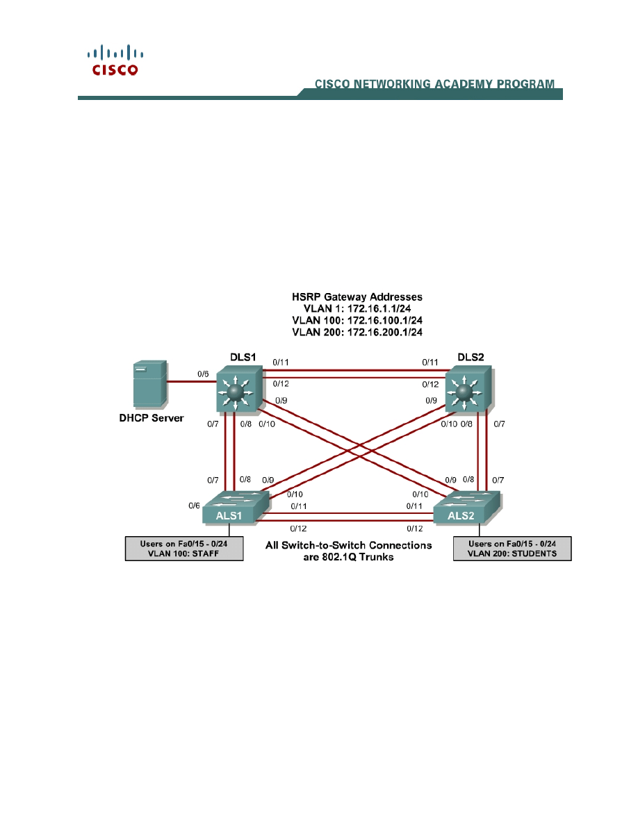
Lab 8-2 Securing Spanning Tree Protocol
Learning Objectives
• Secure the Layer 2 spanning tree topology with BPDU guard
• Protect the primary and secondary root bridge with root guard
• Protect switchports from unidirectional links with UDLD
Topology
Scenario
This lab is a continuation of Lab 8.1 and uses the network configuration set up
in that lab.
In this lab, you will secure the network against possible spanning tree
disruptions, such as rogue access point additions and the loss of stability to the
root bridge with the addition of switches to the network. The improper addition
of switches to the network can be either malicious or accidental. In either case,
the network can be secured against such a disruption.

2 - 22
CCNP: Building Multilayer Switched Networks v5.0 - Lab 8-2
Copyright
© 2006, Cisco Systems, Inc
Step 1
Verify the configurations from Lab 8.1 by issuing the show vtp status
command on ALS2. The output should show that the current VTP domain is
SWPOD, and VLANs 100 and 200 should be represented in the number of
existing VLANs.
ALS2# show vtp status
VTP Version : 2
Configuration Revision : 4
Maximum VLANs supported locally : 255
Number of existing VLANs : 7
VTP Operating Mode : Client
VTP Domain Name : SWPOD
VTP Pruning Mode : Disabled
VTP V2 Mode : Disabled
VTP Traps Generation : Disabled
MD5 digest : 0x18 0x59 0xE2 0xE0 0x28 0xF3 0xE7 0xD1
Configuration last modified by 172.16.1.3 at 3-12-93 19:46:16
ALS1#
1. How many VLANs exist in the network? How many of these are defaults?
Issue the show vlan command on DLS1. The student and staff VLANs should
be represented in the output of this command.
DLS1# show vlan
VLAN Name Status Ports
---- -------------------------------- --------- ------------------------------
-
1 default active Fa0/1, Fa0/2, Fa0/3, Fa0/4
Fa0/5, Fa0/6, Fa0/13, Fa0/14
Fa0/15, Fa0/16, Fa0/17, Fa0/18
Fa0/19, Fa0/20, Fa0/21, Fa0/22
Fa0/23, Fa0/24, Gi0/1, Gi0/2
100 staff active
200 student active
1002 fddi-default act/unsup
1003 token-ring-default act/unsup
1004 fddinet-default act/unsup
1005 trnet-default act/unsup
VLAN Type SAID MTU Parent RingNo BridgeNo Stp BrdgMode Trans1 Trans2
---- ----- ---------- ----- ------ ------ -------- ---- -------- ------ ------
1 enet 100001 1500 - - - - - 0 0
100 enet 100100 1500 - - - - - 0 0
200 enet 100200 1500 - - - - - 0 0
1002 fddi 101002 1500 - - - - - 0 0
1003 tr 101003 1500 - - - - - 0 0
1004 fdnet 101004 1500 - - - ieee - 0 0
VLAN Type SAID MTU Parent RingNo BridgeNo Stp BrdgMode Trans1 Trans2
---- ----- ---------- ----- ------ ------ -------- ---- -------- ------ ------
1005 trnet 101005 1500 - - - ibm - 0 0

3 - 22
CCNP: Building Multilayer Switched Networks v5.0 - Lab 8-2
Copyright
© 2006, Cisco Systems, Inc
Remote SPAN VLANs
------------------------------------------------------------------------------
Primary Secondary Type Ports
------- --------- ----------------- ------------------------------------------
DLS1#
2. Which ports are not showing as active for VLAN 1? Why is this?
Issue the show interface trunk command on DLS2. If trunking was configured
properly in Lab 8.1, FastEthernet 0/7 – 0/12 should be in trunking mode on all
switches.
DLS2# show int trunk
Port Mode Encapsulation Status Native vlan
Fa0/7 on 802.1q trunking 1
Fa0/8 on 802.1q trunking 1
Fa0/9 on 802.1q trunking 1
Fa0/10 on 802.1q trunking 1
Fa0/11 on 802.1q trunking 1
Fa0/12 on 802.1q trunking 1
Port Vlans allowed on trunk
Fa0/7 1-4094
Fa0/8 1-4094
Fa0/9 1-4094
Fa0/10 1-4094
Fa0/11 1-4094
Fa0/12 1-4094
Port Vlans allowed and active in management domain
Fa0/7 1,100,200
Fa0/8 1,100,200
Fa0/9 1,100,200
Fa0/10 1,100,200
Fa0/11 1,100,200
Port Vlans allowed and active in management domain
Fa0/12 1,100,200
Port Vlans in spanning tree forwarding state and not pruned
Fa0/7 1,100,200
Fa0/8 1,100,200
Fa0/9 1,100,200
Fa0/10 1,100,200
Fa0/11 1,100,200
Fa0/12 1,100,200
DLS2#

4 - 22
CCNP: Building Multilayer Switched Networks v5.0 - Lab 8-2
Copyright
© 2006, Cisco Systems, Inc
3. Are any VLANs being pruned from these trunks? How can you tell?
Issue the show spanning-tree vlan 1 command on DLS2. The results from this
command may vary, and DLS2 may or may not be the root in your topology. In
the following output, this bridge is currently the root of the spanning tree.
DLS2# show spanning-tree vlan 1
VLAN0001
Spanning tree enabled protocol ieee
Root ID Priority 32769
Address 000a.b8a9.d680
This bridge is the root
Hello Time 2 sec Max Age 20 sec Forward Delay 15 sec
Bridge ID Priority 32769 (priority 32768 sys-id-ext 1)
Address 000a.b8a9.d680
Hello Time 2 sec Max Age 20 sec Forward Delay 15 sec
Aging Time 300
Interface Role Sts Cost Prio.Nbr Type
---------------- ---- --- --------- -------- --------------------------------
Fa0/7 Desg FWD 19 128.9 P2p
Fa0/8 Desg FWD 19 128.10 P2p
Fa0/9 Desg FWD 19 128.11 P2p
Fa0/10 Desg FWD 19 128.12 P2p
Fa0/11 Desg FWD 19 128.13 P2p
Fa0/12 Desg FWD 19 128.14 P2p
DLS2#
4. Where is the spanning tree root in your lab network? Is this root bridge
optimal for your network?
5. What is the ID priority of the current bridge?
Step 2
In most cases, you must manually configure the spanning tree root to ensure
optimized paths throughout the Layer 2 network. This topic is covered in
Module 3. For this scenario, DLS1 acts as the root for VLANs 1 and 100, and

5 - 22
CCNP: Building Multilayer Switched Networks v5.0 - Lab 8-2
Copyright
© 2006, Cisco Systems, Inc
performs the secondary function for VLAN 200. In addition, DLS2 is the primary
root bridge for VLAN 200, and secondary for VLANs 1 and 100.
You can configure STP priority for the primary and secondary roots using the
spanning-tree vlan vlan ID root {primary | secondary} command.
DLS1#config t
Enter configuration commands, one per line. End with CNTL/Z
DLS1(config)#spanning-tree vlan 1,100 root primary
DLS1(config)#spanning-tree vlan 200 root secondary
DLS1(config)#end
DLS2#config t
Enter configuration commands, one per line. End with CNTL/Z
DLS2(config)#spanning-tree vlan 1,100 root secondary
DLS2(config)#spanning-tree vlan 200 root primary
DLS2(config)#end
Verify your configuration on both DLS1 and DLS2 using the show spanning-
tree command.
DLS2# show spanning-tree
VLAN0001
Spanning tree enabled protocol ieee
Root ID Priority 24577
Address 000a.b8a9.d780
Cost 19
Port 13 (FastEthernet0/11)
Hello Time 2 sec Max Age 20 sec Forward Delay 15 sec
Bridge ID Priority 28673 (priority 28672 sys-id-ext 1)
Address 000a.b8a9.d680
Hello Time 2 sec Max Age 20 sec Forward Delay 15 sec
Aging Time 300
Interface Role Sts Cost Prio.Nbr Type
---------------- ---- --- --------- -------- --------------------------------
Fa0/7 Desg FWD 19 128.9 P2p
Fa0/8 Desg FWD 19 128.10 P2p
Fa0/9 Desg FWD 19 128.11 P2p
Fa0/10 Desg FWD 19 128.12 P2p
Fa0/11 Root FWD 19 128.13 P2p
Fa0/12 Altn BLK 19 128.14 P2p
VLAN0100
Spanning tree enabled protocol ieee
Root ID Priority 24676
Address 000a.b8a9.d780
Cost 19
Port 13 (FastEthernet0/11)
Hello Time 2 sec Max Age 20 sec Forward Delay 15 sec
Bridge ID Priority 28772 (priority 28672 sys-id-ext 100)
Address 000a.b8a9.d680
Hello Time 2 sec Max Age 20 sec Forward Delay 15 sec
Aging Time 300
Interface Role Sts Cost Prio.Nbr Type

6 - 22
CCNP: Building Multilayer Switched Networks v5.0 - Lab 8-2
Copyright
© 2006, Cisco Systems, Inc
---------------- ---- --- --------- -------- --------------------------------
Fa0/7 Desg FWD 19 128.9 P2p
Fa0/8 Desg FWD 19 128.10 P2p
Fa0/9 Desg FWD 19 128.11 P2p
Fa0/10 Desg FWD 19 128.12 P2p
Fa0/11 Root FWD 19 128.13 P2p
Fa0/12 Altn BLK 19 128.14 P2p
VLAN0200
Spanning tree enabled protocol ieee
Root ID Priority 24776
Address 000a.b8a9.d680
This bridge is the root
Hello Time 2 sec Max Age 20 sec Forward Delay 15 sec
Bridge ID Priority 24776 (priority 24576 sys-id-ext 200)
Address 000a.b8a9.d680
Hello Time 2 sec Max Age 20 sec Forward Delay 15 sec
Aging Time 300
Interface Role Sts Cost Prio.Nbr Type
---------------- ---- --- --------- -------- --------------------------------
Fa0/7 Desg FWD 19 128.9 P2p
Fa0/8 Desg FWD 19 128.10 P2p
Fa0/9 Desg FWD 19 128.11 P2p
Fa0/10 Desg FWD 19 128.12 P2p
Fa0/11 Desg FWD 19 128.13 P2p
Fa0/12 Desg FWD 19 128.14 P2p
DLS2#
6. According to the output, what is the root for VLAN 100? For VLAN 200?
Step 3
To maintain an efficient STP topology, the root bridge must remain predictable.
If a foreign or rogue switch is maliciously or accidentally added to the network,
the STP topology could be changed if the new switch has a lower BID than the
current root bridge. Root guard helps prevent this by putting a port that hears
these BPDUs in the root-inconsistent state. Data cannot be sent or received
over the port while it is in this state, but the switch can listen to BPDUs received
on the port to detect a new root advertising itself.
Root guard is enabled on a per-port basis with the spanning-tree guard root
command. You should use root guard on switchports where you would never
expect to find the root bridge for a VLAN.
In the topology diagram, Fast Ethernet ports 0/13 and 0/14 on each switch are
not being used as trunk or access ports. It is possible that a switch could be

7 - 22
CCNP: Building Multilayer Switched Networks v5.0 - Lab 8-2
Copyright
© 2006, Cisco Systems, Inc
accidentally or maliciously added to those ports. Set up root guard on these
ports to ensure that if a switch is added, it is not allowed to take over as root.
DLS1#configure terminal
Enter configuration commands, one per line. End with CNTL/Z.
DLS1(config)#interface range fastEthernet 0/13 - 14
DLS1(config-if-range)#spanning-tree guard root
DLS1(config-if-range)#end
DLS1#
Configure the same on DLS2, ALS1, and ALS2.
7. What will happen if a switch is connected to FA0/13 via a crossover cable?
Step 4
Verify your configuration to make sure that root guard was not accidentally
configured on a port that should hear root advertisements, such as a port on
ALS2 that is connected to the root bridge. Use the show spanning-tree vlan 1
command on ALS2 to look for a root port. In the following example, FA0/9 is a
root port for VLAN 1 on ALS2.
ALS2# show spanning-tree vlan 1
VLAN0001
Spanning tree enabled protocol ieee
Root ID Priority 24577
Address 000a.b8a9.d780
Cost 19
Port 11 (FastEthernet0/9)
Hello Time 2 sec Max Age 20 sec Forward Delay 15 sec
Bridge ID Priority 32769 (priority 32768 sys-id-ext 1)
Address 0019.068d.6980
Hello Time 2 sec Max Age 20 sec Forward Delay 15 sec
Aging Time 300
Interface Role Sts Cost Prio.Nbr Type
---------------- ---- --- --------- -------- --------------------------------
Fa0/5 Desg FWD 19 128.7 P2p
Fa0/7 Altn BLK 19 128.9 P2p
Fa0/8 Altn BLK 19 128.10 P2p
Fa0/9 Root FWD 19 128.11 P2p
Fa0/10 Altn BLK 19 128.12 P2p
Configure root guard on the root port that you found. Note that this configuration
is for teaching purposes only. This would NOT be done in a production network.
ALS2#configure terminal
Enter configuration commands, one per line. End with CNTL/Z.
ALS2(config)#interface FastEthernet 0/9
ALS2(config-if)#spanning-tree guard root
ALS2(config-if)#end

8 - 22
CCNP: Building Multilayer Switched Networks v5.0 - Lab 8-2
Copyright
© 2006, Cisco Systems, Inc
Notice that as soon as you issue this command, you receive a message that
root guard has been enabled and that the port is now in the blocking state for
the specific VLANs configured. This port has been transitioned to this state
because it receives a BPDU that claims to be the root.
1w4d: %SPANTREE-2-ROOTGUARD_CONFIG_CHANGE: Root guard enabled on port
FastEthernet0/9.
1w4d: %SPANTREE-2-ROOTGUARD_BLOCK: Root guard blocking port FastEthernet0/9 on
VLAN0100.
1w4d: %SPANTREE-2-ROOTGUARD_BLOCK: Root guard blocking port FastEthernet0/9 on
VLAN0200.
Verify which ports are in this inconsistent state with the show spanning-tree
inconsistentports command.
ALS2# show spanning-tree inconsistentports
Name Interface Inconsistency
-------------------- ---------------------- ------------------
VLAN0001 FastEthernet0/9 Root Inconsistent
VLAN0100 FastEthernet0/9 Root Inconsistent
VLAN0200 FastEthernet0/9 Root Inconsistent
Number of inconsistent ports (segments) in the system : 3
Since this configuration is not intended for normal operation, remove it using the
no spanning-tree guard root command.
ALS2#configure terminal
Enter configuration commands, one per line. End with CNTL/Z.
ALS2(config)#interface FastEthernet 0/9
ALS2(config-if)#no spanning-tree guard root
ALS2(config-if)#end
Once removed, a message indicates that the port is being unblocked.
1w4d: %SPANTREE-2-ROOTGUARD_CONFIG_CHANGE: Root guard disabled on port
FastEthernet0/9.
1w4d: %SPANTREE-2-ROOTGUARD_UNBLOCK: Root guard unblocking port
FastEthernet0/9 on VLAN0001.
Step 5
Because PortFast is enabled on all user access ports on ALS1 and ALS2,
BPDUs are not expected to be heard on these ports. Any BPDUs that are heard
could disrupt the STP topology, so you should protect these ports from
accidental or malicious behavior that could cause BPDUs. If a rogue access
point or switch is placed on these ports, BPDUs would most likely be heard.
BPDU guard protects ports from this type of situation by placing the interface in
the error-disable state. The BPDU guard feature provides a secure response to
invalid configurations because the network administrator must manually put the
interface back in service.

9 - 22
CCNP: Building Multilayer Switched Networks v5.0 - Lab 8-2
Copyright
© 2006, Cisco Systems, Inc
To enable BPDU guard on PortFast-enabled ports, use the global configuration
command spanning-tree portfast bpduguard default.
ALS1#config t
Enter configuration commands, one per line. End with CNTL/Z.
ALS1(config)#spanning-tree portfast bpduguard default
ALS1(config)#end
ALS2#config t
Enter configuration commands, one per line. End with CNTL/Z.
ALS2(config)#spanning-tree portfast bpduguard default
ALS2(config)#end
Verify your configuration using the show spanning-tree summary command.
ALS2# show spanning-tree summary
Switch is in pvst mode
Root bridge for: none
Extended system ID is enabled
Portfast Default is disabled
PortFast BPDU Guard Default is enabled
Portfast BPDU Filter Default is disabled
Loopguard Default is disabled
EtherChannel misconfig guard is enabled
UplinkFast is disabled
BackboneFast is disabled
Configured Pathcost method used is short
Name Blocking Listening Learning Forwarding STP Active
---------------------- -------- --------- -------- ---------- ----------
VLAN0001 5 0 0 2 7
VLAN0100 5 0 0 1 6
VLAN0200 5 0 0 1 6
---------------------- -------- --------- -------- ---------- ----------
3 vlans 15 0 0 4 19
ALS2#
8. What action will be taken if a wireless access point sending BPDUs is
connected to FA0/15 on ALS1?
Step 6
A unidirectional link occurs when traffic is transmitted between neighbors in one
direction only. Unidirectional links can cause spanning tree topology loops.
UDLD allows devices to detect when a unidirectional link exists and shut down
the affected interface.
You can configure UDLD on a per port basis or globally for all gigabit interfaces.
The aggressive keyword places the port in the error-disable state when a
violation occurs on the port.

10 - 22
CCNP: Building Multilayer Switched Networks v5.0 - Lab 8-2
Copyright
© 2006, Cisco Systems, Inc
Enable UDLD protection on Fast Ethernet ports 1 – 24 on all switches using the
UDLD port aggressive command. Configure UDLD globally for all gigabit
interfaces for future use using the UDLD enable command.
DLS1#config t
Enter configuration commands, one per line. End with CNTL/Z.
DLS1(config)#interface range FastEthernet 0/1 - 24
DLS1(config-if-range)#udld port aggressive
DLS1(config-if-range)#exit
DLS1(config)#udld enable
DLS1(config)#end
DLS2#config t
Enter configuration commands, one per line. End with CNTL/Z.
DLS2(config)#interface range FastEthernet 0/1 - 24
DLS2(config-if-range)#udld port aggressive
DLS2(config-if-range)#exit
DLS2(config)#udld enable
DLS2(config)#end
ALS1#config t
Enter configuration commands, one per line. End with CNTL/Z.
ALS1(config)#interface range FastEthernet 0/1 - 24
ALS1(config-if-range)#udld port aggressive
ALS1(config-if-range)#exit
ALS1(config)#udld enable
ALS1(config)#end
ALS2#config t
Enter configuration commands, one per line. End with CNTL/Z.
ALS2(config)#interface range FastEthernet 0/1 - 24
ALS2(config-if-range)#udld port aggressive
ALS2(config-if-range)#exit
ALS2(config)#udld enable
ALS2(config)#end
DLS1(config)#udld ?
aggressive Enable UDLD protocol in aggressive mode on fiber ports except
where locally configured
enable Enable UDLD protocol on fiber ports except where locally
configured
Verify your configuration using the show UDLD interface ID command.
ALS2# show udld fa 0/15
Interface Fa0/15
---
Port enable administrative configuration setting: Enabled / in aggressive mode
Port enable operational state: Enabled / in aggressive mode
Current bidirectional state: Unknown
Current operational state: Link down
Message interval: 7
Time out interval: 5
No neighbor cache information stored
9. What is the operation state of this interface?

11 - 22
CCNP: Building Multilayer Switched Networks v5.0 - Lab 8-2
Copyright
© 2006, Cisco Systems, Inc
Note: Keep all configurations from this lab for the next Layer 2 security lab.
Final Configurations
DLS1#show run
Building configuration...
Current configuration : 2928 bytes
!
!
hostname DLS1
!
enable secret cisco
!
!
udld enable
!
!
ip dhcp snooping vlan 100,200
ip dhcp snooping
!
!
spanning-tree mode pvst
spanning-tree extend system-id
spanning-tree vlan 1,100 priority 24576
spanning-tree vlan 200 priority 28672
!
!
interface FastEthernet0/1
udld port aggressive
!
interface FastEthernet0/2
udld port aggressive
!
interface FastEthernet0/3
udld port aggressive
!
interface FastEthernet0/4
udld port aggressive
!
interface FastEthernet0/5
udld port aggressive
!
interface FastEthernet0/6
udld port aggressive
ip dhcp snooping trust
!
interface FastEthernet0/7
switchport trunk encapsulation dot1q
switchport mode trunk
udld port aggressive
ip dhcp snooping trust
!
interface FastEthernet0/8
switchport trunk encapsulation dot1q
switchport mode trunk
udld port aggressive
ip dhcp snooping trust
!
interface FastEthernet0/9

12 - 22
CCNP: Building Multilayer Switched Networks v5.0 - Lab 8-2
Copyright
© 2006, Cisco Systems, Inc
switchport trunk encapsulation dot1q
switchport mode trunk
udld port aggressive
ip dhcp snooping trust
!
interface FastEthernet0/10
switchport trunk encapsulation dot1q
switchport mode trunk
udld port aggressive
ip dhcp snooping trust
!
interface FastEthernet0/11
switchport trunk encapsulation dot1q
switchport mode trunk
udld port aggressive
ip dhcp snooping trust
!
interface FastEthernet0/12
switchport trunk encapsulation dot1q
switchport mode trunk
udld port aggressive
ip dhcp snooping trust
!
interface FastEthernet0/13
udld port aggressive
spanning-tree guard root
!
interface FastEthernet0/14
udld port aggressive
spanning-tree guard root
!
interface FastEthernet0/15
udld port aggressive
!
interface FastEthernet0/16
udld port aggressive
!
interface FastEthernet0/17
udld port aggressive
!
interface FastEthernet0/18
udld port aggressive
!
interface FastEthernet0/19
udld port aggressive
!
interface FastEthernet0/20
udld port aggressive
!
interface FastEthernet0/21
udld port aggressive
!
interface FastEthernet0/22
udld port aggressive
!
interface FastEthernet0/23
udld port aggressive
!
interface FastEthernet0/24
udld port aggressive
!
interface GigabitEthernet0/1
!

13 - 22
CCNP: Building Multilayer Switched Networks v5.0 - Lab 8-2
Copyright
© 2006, Cisco Systems, Inc
interface GigabitEthernet0/2
!
interface Vlan1
ip address 172.16.1.3 255.255.255.0
standby 1 ip 172.16.1.1
standby 1 priority 150
standby 1 preempt
no shutdown
!
interface Vlan100
ip address 172.16.100.3 255.255.255.0
standby 1 ip 172.16.100.1
standby 1 priority 150
standby 1 preempt
no shutdown
!
interface Vlan200
ip address 172.16.200.3 255.255.255.0
standby 1 ip 172.16.200.1
standby 1 preempt
no shutdown
!
!
line con 0
password cisco
login
line vty 0 4
password cisco
login
line vty 5 15
password cisco
login
!
end
DLS2#show run
Building configuration...
Current configuration : 2880 bytes
!
!
hostname DLS2
!
enable secret cisco
!
!
udld enable
!
!
ip dhcp snooping vlan 100,200
ip dhcp snooping
!
!
spanning-tree mode pvst
spanning-tree extend system-id
spanning-tree vlan 1,100 priority 28672
spanning-tree vlan 200 priority 24576
!

14 - 22
CCNP: Building Multilayer Switched Networks v5.0 - Lab 8-2
Copyright
© 2006, Cisco Systems, Inc
!
interface FastEthernet0/1
udld port aggressive
!
interface FastEthernet0/2
udld port aggressive
!
interface FastEthernet0/3
udld port aggressive
!
interface FastEthernet0/4
udld port aggressive
!
interface FastEthernet0/5
udld port aggressive
!
interface FastEthernet0/6
udld port aggressive
!
interface FastEthernet0/7
switchport trunk encapsulation dot1q
switchport mode trunk
udld port aggressive
ip dhcp snooping trust
!
interface FastEthernet0/8
switchport trunk encapsulation dot1q
switchport mode trunk
udld port aggressive
ip dhcp snooping trust
!
interface FastEthernet0/9
switchport trunk encapsulation dot1q
switchport mode trunk
udld port aggressive
ip dhcp snooping trust
!
interface FastEthernet0/10
switchport trunk encapsulation dot1q
switchport mode trunk
udld port aggressive
ip dhcp snooping trust
!
interface FastEthernet0/11
switchport trunk encapsulation dot1q
switchport mode trunk
udld port aggressive
ip dhcp snooping trust
!
interface FastEthernet0/12
switchport trunk encapsulation dot1q
switchport mode trunk
udld port aggressive
ip dhcp snooping trust
!
interface FastEthernet0/13
udld port aggressive
spanning-tree guard root
!
interface FastEthernet0/14
udld port aggressive
spanning-tree guard root
!

15 - 22
CCNP: Building Multilayer Switched Networks v5.0 - Lab 8-2
Copyright
© 2006, Cisco Systems, Inc
interface FastEthernet0/15
udld port aggressive
!
interface FastEthernet0/16
udld port aggressive
!
interface FastEthernet0/17
udld port aggressive
!
interface FastEthernet0/18
udld port aggressive
!
interface FastEthernet0/19
udld port aggressive
!
interface FastEthernet0/20
udld port aggressive
!
interface FastEthernet0/21
udld port aggressive
!
interface FastEthernet0/22
udld port aggressive
!
interface FastEthernet0/23
udld port aggressive
!
interface FastEthernet0/24
udld port aggressive
!
interface GigabitEthernet0/1
!
interface GigabitEthernet0/2
!
interface Vlan1
ip address 172.16.1.4 255.255.255.0
standby 1 ip 172.16.1.1
standby 1 preempt
no shutdown
!
interface Vlan100
ip address 172.16.100.4 255.255.255.0
standby 1 ip 172.16.100.1
standby 1 preempt
no shutdown
!
interface Vlan200
ip address 172.16.200.4 255.255.255.0
standby 1 ip 172.16.200.1
standby 1 priority 150
standby 1 preempt
no shutdown
!
!
line con 0
password cisco
login
line vty 0 4
password cisco
login
line vty 5 15
password cisco
login

16 - 22
CCNP: Building Multilayer Switched Networks v5.0 - Lab 8-2
Copyright
© 2006, Cisco Systems, Inc
!
end
ALS1#show run
Building configuration...
Current configuration : 4682 bytes
!
!
hostname ALS1
!
enable secret cisco
!
username janedoe password 0 cisco
username johndoe password 0 cisco
username joesmith password 0 cisco
aaa new-model
aaa authentication dot1x default local
!
aaa session-id common
udld enable
!
!
ip dhcp snooping vlan 100,200
ip dhcp snooping
!
spanning-tree mode pvst
spanning-tree portfast bpduguard default
spanning-tree extend system-id
!
!
interface FastEthernet0/1
udld port aggressive
!
interface FastEthernet0/2
udld port aggressive
!
interface FastEthernet0/3
udld port aggressive
!
interface FastEthernet0/4
udld port aggressive
!
interface FastEthernet0/5
udld port aggressive
!
interface FastEthernet0/6
udld port aggressive
!
interface FastEthernet0/7
switchport mode trunk
udld port aggressive
ip dhcp snooping trust
!
interface FastEthernet0/8
switchport mode trunk
udld port aggressive
ip dhcp snooping trust
!
interface FastEthernet0/9
switchport mode trunk

17 - 22
CCNP: Building Multilayer Switched Networks v5.0 - Lab 8-2
Copyright
© 2006, Cisco Systems, Inc
udld port aggressive
ip dhcp snooping trust
!
interface FastEthernet0/10
switchport mode trunk
udld port aggressive
ip dhcp snooping trust
!
interface FastEthernet0/11
switchport mode trunk
udld port aggressive
ip dhcp snooping trust
!
interface FastEthernet0/12
switchport mode trunk
udld port aggressive
ip dhcp snooping trust
!
interface FastEthernet0/13
udld port aggressive
spanning-tree guard root
!
interface FastEthernet0/14
udld port aggressive
spanning-tree guard root
!
interface FastEthernet0/15
switchport access vlan 100
switchport mode access
switchport port-security maximum 2
switchport port-security mac-address sticky
udld port aggressive
dot1x port-control auto
spanning-tree portfast
ip dhcp snooping limit rate 20
!
interface FastEthernet0/16
switchport access vlan 100
switchport mode access
switchport port-security maximum 2
switchport port-security mac-address sticky
udld port aggressive
dot1x port-control auto
spanning-tree portfast
ip dhcp snooping limit rate 20
!
interface FastEthernet0/17
switchport access vlan 100
switchport mode access
switchport port-security maximum 2
switchport port-security mac-address sticky
udld port aggressive
dot1x port-control auto
spanning-tree portfast
ip dhcp snooping limit rate 20
!
interface FastEthernet0/18
switchport access vlan 100
switchport mode access
switchport port-security maximum 2
switchport port-security mac-address sticky
udld port aggressive
dot1x port-control auto

18 - 22
CCNP: Building Multilayer Switched Networks v5.0 - Lab 8-2
Copyright
© 2006, Cisco Systems, Inc
spanning-tree portfast
ip dhcp snooping limit rate 20
!
interface FastEthernet0/19
switchport access vlan 100
switchport mode access
switchport port-security maximum 2
switchport port-security mac-address sticky
udld port aggressive
dot1x port-control auto
spanning-tree portfast
ip dhcp snooping limit rate 20
!
interface FastEthernet0/20
switchport access vlan 100
switchport mode access
switchport port-security maximum 2
switchport port-security mac-address sticky
udld port aggressive
dot1x port-control auto
spanning-tree portfast
ip dhcp snooping limit rate 20
!
interface FastEthernet0/21
switchport access vlan 100
switchport mode access
switchport port-security maximum 2
switchport port-security mac-address sticky
udld port aggressive
dot1x port-control auto
spanning-tree portfast
ip dhcp snooping limit rate 20
!
interface FastEthernet0/22
switchport access vlan 100
switchport mode access
switchport port-security maximum 2
switchport port-security mac-address sticky
udld port aggressive
dot1x port-control auto
spanning-tree portfast
ip dhcp snooping limit rate 20
!
interface FastEthernet0/23
switchport access vlan 100
switchport mode access
switchport port-security maximum 2
switchport port-security mac-address sticky
udld port aggressive
dot1x port-control auto
spanning-tree portfast
ip dhcp snooping limit rate 20
!
interface FastEthernet0/24
switchport access vlan 100
switchport mode access
switchport port-security maximum 2
switchport port-security mac-address sticky
udld port aggressive
dot1x port-control auto
spanning-tree portfast
ip dhcp snooping limit rate 20
!

19 - 22
CCNP: Building Multilayer Switched Networks v5.0 - Lab 8-2
Copyright
© 2006, Cisco Systems, Inc
interface GigabitEthernet0/1
!
interface GigabitEthernet0/2
!
interface Vlan1
ip address 172.16.1.101 255.255.255.0
no shutdown
!
ip default-gateway 172.16.1.1
!
!
radius-server source-ports 1645-1646
!
line con 0
password cisco
line vty 0 4
password cisco
line vty 5 15
password cisco
!
end
ALS2#show run
Building configuration...
!
!
hostname ALS2
!
enable secret cisco
!
!
udld aggressive
!
!
ip dhcp snooping vlan 100,200
ip dhcp snooping
!
!
spanning-tree mode pvst
spanning-tree portfast bpduguard default
!
!
interface FastEthernet0/1
udld port aggressive
!
interface FastEthernet0/2
udld port aggressive
!
interface FastEthernet0/3
udld port aggressive
!
interface FastEthernet0/4
udld port aggressive
!
interface FastEthernet0/5
udld port aggressive
!
interface FastEthernet0/6
udld port aggressive
!

20 - 22
CCNP: Building Multilayer Switched Networks v5.0 - Lab 8-2
Copyright
© 2006, Cisco Systems, Inc
interface FastEthernet0/7
switchport mode trunk
udld port aggressive
ip dhcp snooping trust
!
interface FastEthernet0/8
switchport mode trunk
udld port aggressive
ip dhcp snooping trust
!
interface FastEthernet0/9
switchport mode trunk
udld port aggressive
ip dhcp snooping trust
!
interface FastEthernet0/10
switchport mode trunk
udld port aggressive
ip dhcp snooping trust
!
interface FastEthernet0/11
switchport mode trunk
udld port aggressive
ip dhcp snooping trust
!
interface FastEthernet0/12
switchport mode trunk
udld port aggressive
ip dhcp snooping trust
!
interface FastEthernet0/13
udld port aggressive
spanning-tree guard root
!
interface FastEthernet0/14
udld port aggressive
spanning-tree guard root
!
interface FastEthernet0/15
switchport access vlan 200
switchport mode access
udld port aggressive
spanning-tree portfast
ip dhcp snooping limit rate 20
!
interface FastEthernet0/16
switchport access vlan 200
switchport mode access
udld port aggressive
spanning-tree portfast
ip dhcp snooping limit rate 20
!
interface FastEthernet0/17
switchport access vlan 200
switchport mode access
udld port aggressive
spanning-tree portfast
ip dhcp snooping limit rate 20
!
interface FastEthernet0/18
switchport access vlan 200
switchport mode access
udld port aggressive

21 - 22
CCNP: Building Multilayer Switched Networks v5.0 - Lab 8-2
Copyright
© 2006, Cisco Systems, Inc
spanning-tree portfast
ip dhcp snooping limit rate 20
!
interface FastEthernet0/19
switchport access vlan 200
switchport mode access
udld port aggressive
spanning-tree portfast
ip dhcp snooping limit rate 20
!
interface FastEthernet0/20
switchport access vlan 200
switchport mode access
udld port aggressive
spanning-tree portfast
ip dhcp snooping limit rate 20
!
interface FastEthernet0/21
switchport access vlan 200
switchport mode access
udld port aggressive
spanning-tree portfast
ip dhcp snooping limit rate 20
!
interface FastEthernet0/22
switchport access vlan 200
switchport mode access
udld port aggressive
spanning-tree portfast
ip dhcp snooping limit rate 20
!
interface FastEthernet0/23
switchport access vlan 200
switchport mode access
udld port aggressive
spanning-tree portfast
ip dhcp snooping limit rate 20
!
interface FastEthernet0/24
switchport access vlan 200
switchport mode access
udld port aggressive
spanning-tree portfast
ip dhcp snooping limit rate 20
!
interface GigabitEthernet0/1
!
interface GigabitEthernet0/2
!
interface Vlan1
ip address 172.16.1.102 255.255.255.0
no shutdown
!
ip default-gateway 172.16.1.1
!
!
line con 0
password cisco
login
line vty 0 4
password cisco
login
line vty 5 15

22 - 22
CCNP: Building Multilayer Switched Networks v5.0 - Lab 8-2
Copyright
© 2006, Cisco Systems, Inc
password cisco
login
!
end
Wyszukiwarka
Podobne podstrony:
CCNP3 lab 3 2 en
CCNP3 lab 2 0 b en
CCNP3 lab 4 1 en
CCNP3 lab 6 2 en
CCNP3 lab 8 1 en
CCNP3 lab 2 1 en
CCNP3 lab 5 1 en
CCNP3 lab 7 1 en
CCNP3 lab 6 3 en
CCNP3 lab 4 2 en
CCNP3 lab 3 5 en
CCNP3 lab 3 1 en
CCNP3 lab 2 0 a en
CCNP3 lab 3 3 en
CCNP3 lab 3 4 en
CCNP3 lab 8 3 en
CCNP3 lab 6 2 opt en
CCNP3 lab 6 1 opt en
NS2 lab 4 4 7 en Configure Cisco IOS IPSec using Pre Shared Keys
więcej podobnych podstron