
TD-x20, TD-x25, TDZ-x20, TDZ-x25
System Reference
February 1998
DHA022630
manuals search engine

Copyright
1998 Intergraph Computer Systems. All rights reserved. This document contains information protected by copyright, trade secret, and
trademark law. This document may not, in whole or in part, be reproduced in any form or by any means, or be used to make any
derivative work, without written consent from Intergraph Computer Systems.
Use, duplication, or disclosure by the United States Government is subject to restrictions as set forth in subdivision (c)(1)(ii) of the rights in
technical data and computer software clause at DFARS 252.227-7013. Unpublished rights are reserved under the copyright laws of the
United States.
Intergraph Computer Systems, Huntsville AL 35894-0001
Notice
Information in this document is subject to change without notice and should not be considered a commitment by Intergraph Computer
Systems. Intergraph Computer Systems shall not be liable for technical or editorial errors in, or omissions from, this document. Intergraph
Computer Systems shall not be liable for incidental or consequential damages resulting from the furnishing or use of this document.
All warranties given by Intergraph Computer Systems about equipment or software are set forth in your purchase contract. Nothing stated
in, or implied by, this document or its contents shall be considered or deemed a modification or amendment of such warranties.
Trademarks
Intergraph
and the Intergraph logo are registered trademarks of Intergraph Corporation. TD
, TDZ
, Intense 3D
, and RealiZm
are
trademarks of Intergraph Corporation. Microsoft
, MS-DOS
, and Windows
are registered trademarks of Microsoft Corporation.
Windows NT
is a trademark of Microsoft Corporation. IntelliMouse
is a trademark of Microsoft Corporation.
Other brands and product names are trademarks of their respective owners.
FCC/DOC Compliance
This equipment has been tested and found to comply with the limits for a Class A digital device, pursuant to part 15 of the FCC Rules.
These limits are designed to provide reasonable protection against harmful interference when the equipment is operated in a commercial
environment. This equipment generates, uses, and can radiate radio frequency energy. If the equipment is not installed and used in
accordance with the instruction manual, it may cause harmful interference to radio communications.
Operation of this equipment in a residential area is likely to cause harmful interference in which case the user will be required to correct the
interference at his own expense.
This Class A digital apparatus meets all requirements of the Canadian Interference-Causing Equipment Regulations. Cet appareil
numérique de la classe A respecte toutes les exigencies du Règlement sur le materiél brouilleur du Canada.
Warnings
Changes or modifications made to the system that are not approved by the party responsible for compliance could void the user's authority
to operate the equipment.
To reduce the risk of electrical shock, do not attempt to open the equipment unless instructed. Do not use a tool for purposes other than
instructed.
There is a danger of explosion if the battery is incorrectly replaced. Replace the battery only with the same or equivalent type as
recommended by the manufacturer. Dispose of used batteries according to the manufacturer's instructions.
There are no user serviceable parts in the power supply. Refer all servicing of the power supply to qualified service personnel.
Notes
This device is designed and manufactured to comply with approved safety standards for information processing and business equipment.
Read all operating instructions before using this device. Keep these instructions for future reference. Follow all warnings on the device or
in the operating instructions.
manuals search engine

iii
Contents
Introduction..................................................................................................................v
Document Conventions..................................................................................................v
Additional System Information ......................................................................................v
1 Opening and Closing the Base Unit ..........................................................................1
Avoiding Electrostatic Discharge ...................................................................................1
Opening the Base Unit ...................................................................................................1
Attaching an Antistatic Wrist Strap ...............................................................................5
Closing the Base Unit ....................................................................................................6
2 Maintaining System Devices .....................................................................................9
Cleaning the System ......................................................................................................9
Replacing System Devices..............................................................................................9
Floppy Disk Drive..........................................................................................10
CD-ROM Drive..............................................................................................11
Device in the Optional Device Bay (Desktop).................................................13
System Hard Disk Drives ...............................................................................14
Auxiliary Hard Disk Drives (Deskside) ..........................................................17
3 Replacing System Components...............................................................................19
SCSI Termination Card (Desktop) ...............................................................................20
Riser Card ...................................................................................................................21
Option Board Fans (Deskside) .....................................................................................24
System Hard Disk Drive Fan (Deskside) ......................................................................24
Processor Module.........................................................................................................26
System Board...............................................................................................................28
Power Supply...............................................................................................................30
CMOS/Clock Battery...................................................................................................33
4 Upgrading the System.............................................................................................35
Adding Main Memory .................................................................................................35
Adding Internal SCSI Devices .....................................................................................36
Adding External SCSI Devices ....................................................................................38
Adding Option Boards .................................................................................................39
Primary PCI Slots...........................................................................................42
PCI Option Boards .........................................................................................42
ISA Option Boards.........................................................................................43
5 Hardware Information............................................................................................45
System Specifications...................................................................................................45
System Model Number.................................................................................................46
Graphics Option Board Slot Assignments ....................................................................47
Desktop System PCI Slot Assignments...........................................................47
Deskside System PCI Slot Assignments..........................................................48
manuals search engine

iv
Sound Controller .........................................................................................................49
DMA Channels ............................................................................................................50
Input/Output Addresses................................................................................................50
Memory Address Map..................................................................................................51
PCI to ISA Bus Interrupt Mapping ...............................................................................51
ISA Bus .......................................................................................................................52
External Port Pinouts ...................................................................................................53
MIDI/Game....................................................................................................53
Parallel...........................................................................................................53
SCSI ..............................................................................................................54
Serial (COM) Ethernet 10/100Base-TX .........................................................55
Mouse and Keyboard......................................................................................55
Universal Serial Bus.......................................................................................56
Video Out VGA In .........................................................................................56
System Board Connector Pinouts .................................................................................57
Floppy Disk....................................................................................................58
Audio.............................................................................................................58
System Board Jumpers.................................................................................................59
CPU Frequency..............................................................................................59
CPU Voltage ..................................................................................................60
Power Supply Information ...........................................................................................60
DC Output Specifications ...............................................................................60
Cable Connectors ...........................................................................................64
P1-P9 Connector Pinouts................................................................................64
Index...........................................................................................................................67
manuals search engine

v
Introduction
TD-x20, TD-x25, TDZ-x20, TDZ-x25 System Reference provides information necessary to
service and upgrade a TD-x20, TD-x25, TDZ-x20, or TDZ-x25 workstation.
Document Conventions
Bold
Commands, words, or characters that you key in literally.
Italic
Variable values that you supply, or cross-references.
Monospace
Output displayed on the screen.
SMALL CAPS
Key names on the keyboard, such as
D
,
ALT
or
F3
; names of files and
directories. You can type filenames and directory names in the dialog boxes
or the command line in lowercase unless directed otherwise.
CTRL
+
D
Press a key while simultaneously pressing another key; for example, press
CTRL
and
D
simultaneously.
Additional System Information
A System Setup guide is shipped with each system, and provides detailed information on the
following:
u
Setting up the system.
u
Configuring the operating system and associated system hardware.
u
Configuring the system’s BIOS.
u
Troubleshooting common system problems.
u
Reinstalling system software.
An online System Introduction is delivered with the system, and provides basic information
on the following:
u
Intergraph Computer Systems support.
u
System hardware features.
u
Basic system controls and connections.
manuals search engine


1
1
Opening and Closing the Base Unit
This chapter describes avoiding electrostatic discharge, opening the TD-x20, TD-x25, TDZ-
x20, and TDZ-x25 workstation’s base unit, attaching an antistatic wrist strap, and closing
the base unit.
Avoiding Electrostatic Discharge
Some of the sensitive components inside the base unit can be damaged by static electricity.
To minimize this possibility, take the following precautions when working with the internal
components of the system to avoid electrostatic discharge.
u
To maintain ground, do not unplug the power cord from the base unit, AC outlet, or
UPS.
u
Touch the bare metal of the base unit to discharge any accumulated electrostatic charge.
u
Do not service the system on surfaces known to have high electrostatic buildup, such as
rugs and carpets. Work on a static-safe surface instead.
u
Handle all printed circuit boards as little as possible and by the edges only. Leave new
parts in their protective packaging until you install them.
u
After opening the base unit, attach an antistatic wrist strap as described in the next
section.
Opening the Base Unit
WARNING
Before opening the base unit, turn the system power off. Use caution when removing
the top cover to avoid injury.
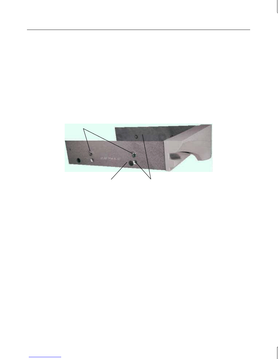
To open the base unit of a desktop system:
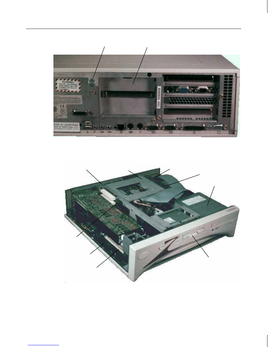
1. Pull the plunger out and rotate it to lock it in the open position. See the following
figure.
manuals search engine
2
Plunger
ISA I/O Panel
2. Lift up the top cover above the ISA I/O panel and pull it up and back.
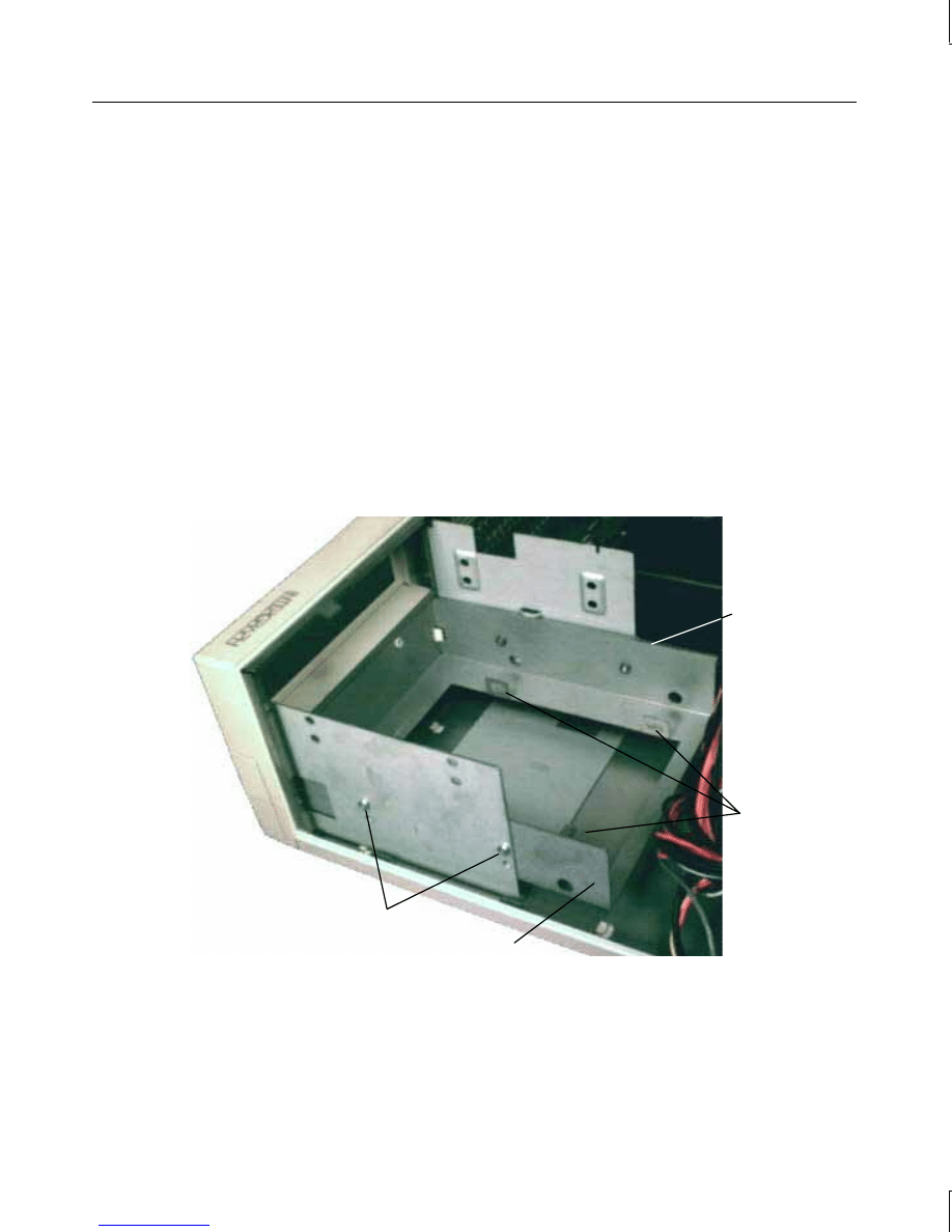
3. Set the top cover aside. The following figure shows inside the base unit.
Floppy
Disk Drive
CD-ROM
Drive
Power Supply
SCSI Terminator
Card
System Hard Disk
Drive Bracket
Riser Card
System
Board
SIMM Sockets
Peripheral
Brace
manuals search engine
3
To open the base unit of a deskside system:
NOTE
The left and right side panels are identified as if you are facing the front of the base unit.
1. Remove the footstands.
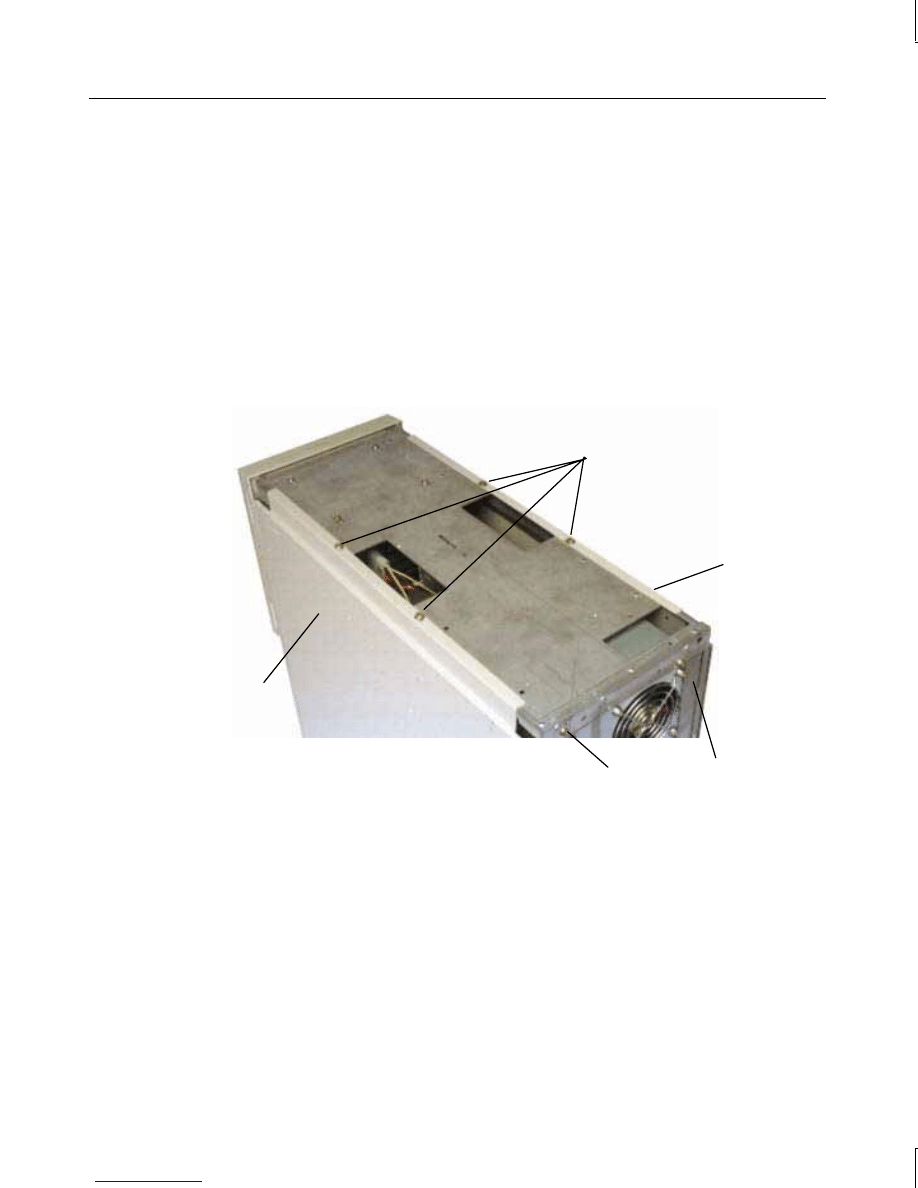
2. Remove the screw on the back of the top cover. Pull the top cover back an inch and lift
it off the base unit. Refer to the following figure.
3. Remove the two screws on the left side panel. Then pull the panel up and out to remove
it. Refer to the following figure.
4. If you are servicing the CD-ROM drive, floppy disk drive, or power supply, remove the
right side panel according to the procedure in step 3 above. Refer to the following
figure.
Right Side
Panel
Left Side
Panel
Back Cover
Screws
Screw
manuals search engine
4
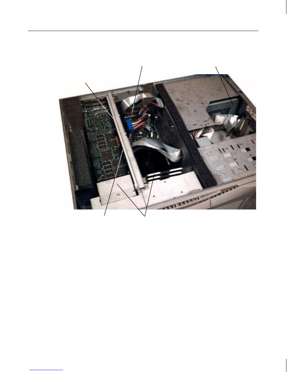
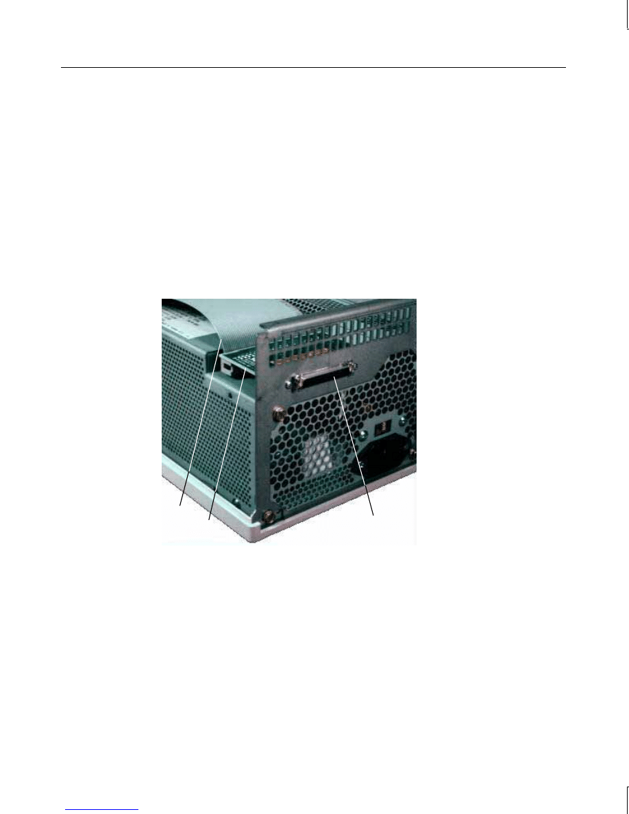
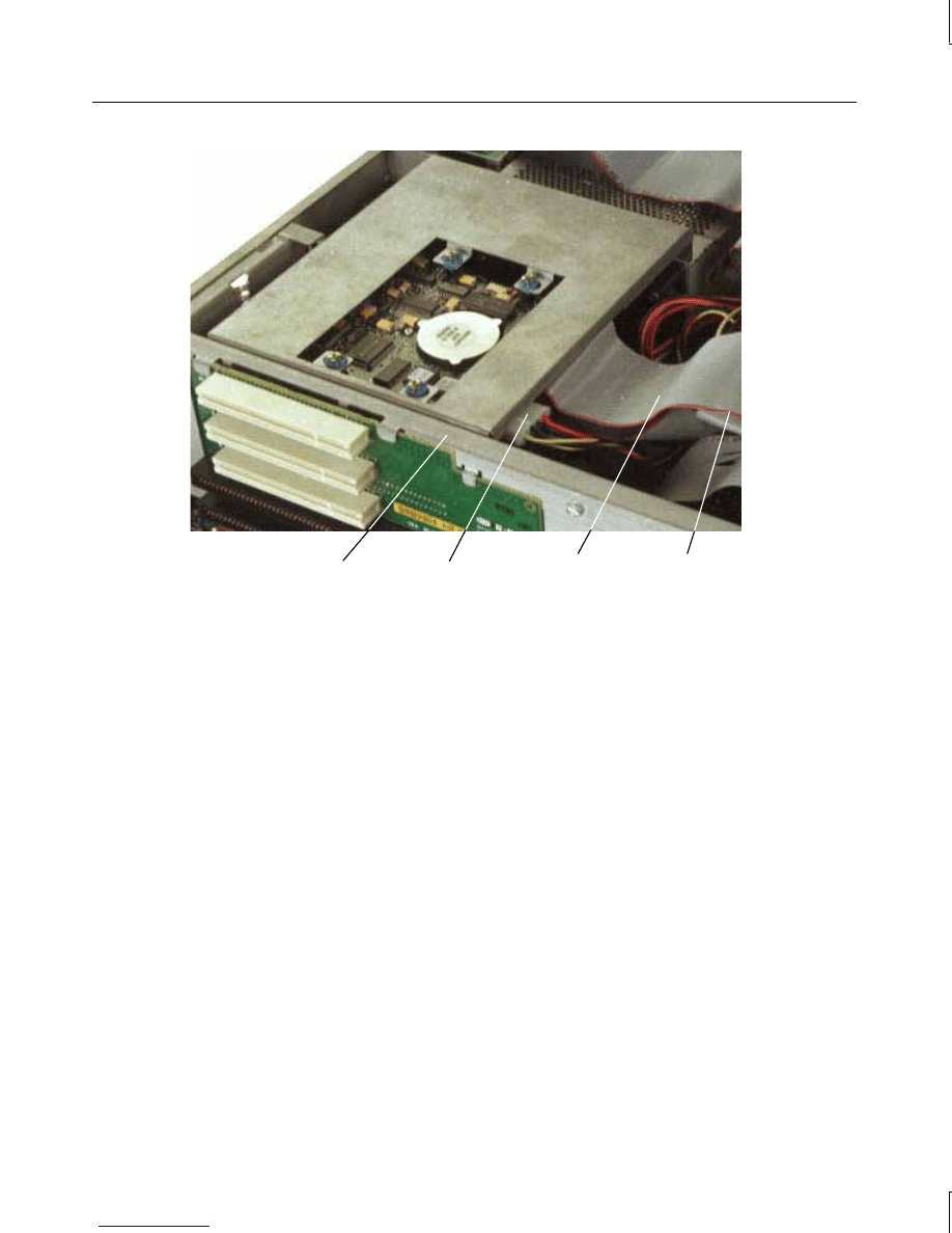
5. Set the cover and panels aside. The following figure shows inside the base unit.
Option Card Guides
Power Supply
Riser Card
(beneath
brace)
External SCSI
Connector
Peripheral Brace
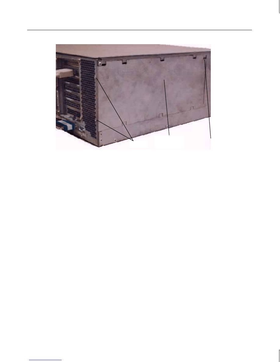
To remove the PCI access panel from a deskside base unit:
1. Power off the base unit and remove the top cover and side panel. Lay the base unit on
the right side.
2. Remove the two screws at the bottom of the unit and the screw behind the PCI access
panel as shown in the following figure.
3. Slide the PCI access panel to the back of the base unit and remove it.
manuals search engine
5
PCI Access
Panel
Screws
Screw
(Behind Panel)
Attaching an Antistatic Wrist Strap
Use a disposable or reusable antistatic wrist strap when servicing or upgrading the
workstation.
NOTE
There is no increased risk of electrical shock when using an antistatic wrist strap. If the wrist
strap does not snugly contact bare skin, static protection will not be effective.
To attach a disposable antistatic wrist strap:
1. Remove the wrist strap from the envelope.
2. Unfold the wrist strap and wrap the exposed adhesive side firmly around your bare wrist.
3. Peel the liner from the wrist strap copper foil. Attach the adhesive side of the copper
foil to a bare flat metal surface (electrical ground) inside the base unit.
NOTE
After using a disposable wrist strap once, you cannot use it again.
To attach a reusable antistatic wrist strap:
1. Attach the wrist strap to the ground loop shown in the following figure.
manuals search engine
6
I/O Lock
Bracket
Desktop
Ground Loop
I/O Lock
Bracket
Deskside
Ground Loop
2. Slip the elastic end of the wrist strap snugly around your bare wrist.
NOTE
The metal conductor bead in the elastic must contact bare skin.
Closing the Base Unit
To close the base unit of a desktop system:
1. Remove the antistatic wrist strap from the ground loop inside the base unit.
2. Replace the top cover by aligning the tabs on the front of the top cover with the notches
behind the faceplate.
3. Lower the back of the top cover and slide it into place.
4. Turn the plunger to lock the top cover to the base unit.
To close the base unit of a deskside system:
1. Remove the antistatic wrist strap from the ground loop inside the base unit.
2. Replace the PCI access panel if removed.
3. Set the base unit in the upright position.
4. Replace the left or right side panel if removed.
5. Replace the top cover. Ensure the top cover is completely installed so the safety
interlock switch engages. If the cover is not properly installed, the system will not start.
6. Replace the footstands.
manuals search engine

7
CAUTION
After servicing or upgrading the system, always replace all panels and covers. The panels
and covers ensure the system maintains proper air flow, so internal components do not
overheat. Overheated components may fail prematurely and may be dangerous to touch.
The panels and covers also ensure electromagnetic interference (EMI) emissions are kept to
levels below the standard requirements.
manuals search engine


9
2
Maintaining System Devices
This chapter describes cleaning the system and replacing system devices in the TD-x20,
TD-x25, TDZ-x20, and TDZ-x25 workstations.
Cleaning the System
Follow these guidelines for cleaning the system.
CAUTION
Power off the system before cleaning the exterior surfaces, mouse, and keyboard. Do not
clean the CD-ROM drive.
Exterior Surfaces
Use a mild cleaning detergent and a clean cloth to clean the monitor screen and the exterior
surfaces of the base unit.
Mouse
On the bottom of the mouse, a retaining ring holds the tracking ball in place. To clean the
mouse, remove the retaining ring and turn the mouse over; the tracking ball will fall out.
Blow gently into the opening. Clean the tracking ball and rollers with a cotton swab and
alcohol. Replace the tracking ball and the retaining ring.
Keyboard
Dust the keyboard with a dry cloth. Aerosol cleaners are commercially available to remove
the dust between the keys of the keyboard. Never allow moisture on the keyboard or the
surface beneath the keys.
Replacing System Devices
This section describes replacing the following system devices:
u
Floppy disk drive
u
CD-ROM drive
u
Device in the optional device bay (desktop)
u
System hard disk drives
u
Auxiliary hard disk drives (deskside)
manuals search engine
10
You will need the following tools to service the system:
u
Quarter-inch nutdriver
u
No. 1 Phillips screwdriver
u
No. 2 Phillips screwdriver
u
Three-sixteenth-inch nutdriver
u
Five-sixteenth-inch or 8 mm nutdriver
u
Small single-slot screwdriver
Open the base unit, take precautions against electrostatic discharge, and attach an antistatic
wrist strap as described in Chapter 1, “Opening and Closing the Base Unit,” before replacing
any parts. After replacing system parts, close the base unit as described in Chapter 1.
CAUTION
The parts inside the base unit are designed to fit within very tight tolerances. Some force is
required to remove or insert parts. However, if you cannot remove or install a part properly,
ensure that there are no obstructions hindering the part.
NOTE
“Right side” and “left side” are as seen from the front of the base unit.
Floppy Disk Drive
To remove the floppy disk drive:
1. Disconnect the cables. Note the position of pin 1 (identified by the red stripe) on the floppy
drive cable. Refer to the following figure.
Power Cable
Connector
Data Cable
Connector
Floppy
Disk Drive
manuals search engine
11
2. Remove the screws holding the drive to each side of the chassis, if necessary. Slide the
drive and its support bracket out of the base unit.
3. Remove the screws holding the drive to the support bracket, and then remove the drive
from the bracket.
To install a new floppy disk drive:
1. Mount the replacement drive to the support bracket using the screws removed
previously.
2. Install the drive and its support bracket into the base unit. In a deskside system, secure
the drive to the chassis using the screws removed previously, then connect the cables to
the device.
CD-ROM Drive
To remove the CD-ROM drive:
1. In a desktop system, remove the floppy disk drive as described previously in “Floppy
Disk Drive,” leaving the cables attached.
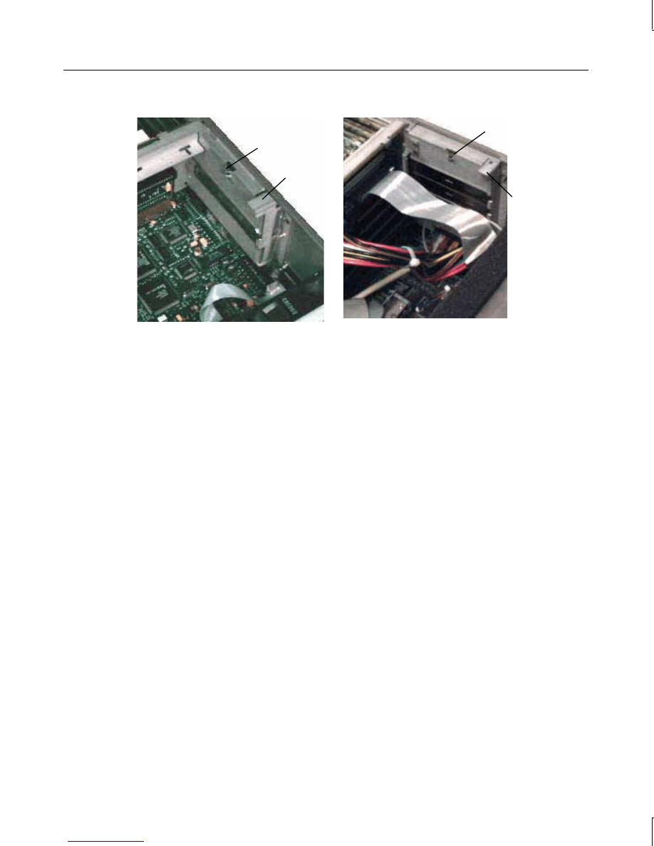
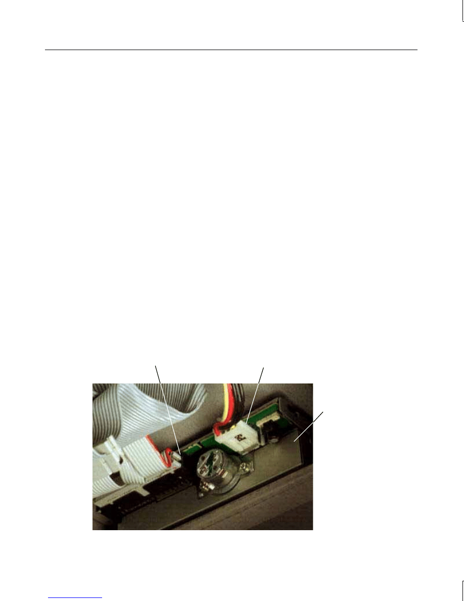
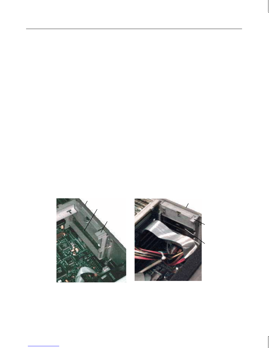
2. Disconnect the cables from the CD-ROM drive. Refer to the following figures.
Power
Cable
SCSI
Cable
Audio
Cable
Screws
CD-ROM
Drive
manuals search engine
12
CD-ROM Drive
Power Cable
Screws
IDE Cable
Audio Cable
3. Disconnect the audio cable from its system board connector.
4. Remove the screws holding the CD-ROM drive to each side of the chassis.
5. Slide the CD-ROM drive forward and out of the base unit.
To install a new CD-ROM drive:
1. Disable SCSI termination and set the SCSI ID. Refer to the vendor’s CD-ROM drive
documentation for instructions.
2. Insert the new CD-ROM drive through the front panel.
3. Secure the CD-ROM drive to the chassis using the screws removed previously.
4. Connect the SCSI cable and power cable to the CD-ROM drive. The SCSI cable is
keyed to ensure proper insertion, so that the red stripe (pin 1) is adjacent to the power
connector.
5. If installing an Intergraph CD-ROM drive, the audio cable is already connected to the
drive. Connect the loose end of the audio cable to the system board connector.
6. If installing a non-Intergraph CD-ROM drive, connect the audio cable delivered with
the new CD-ROM drive to the connectors on the drive and the system board.
7. Replace the floppy disk drive.
manuals search engine
13
Device in the Optional Device Bay (Desktop)
An optional device bay, located under the CD-ROM drive in a desktop system, is designed to
hold an optional peripheral device.
To remove a device in the optional device bay:
1. Disconnect the cables from the device. Refer to the documentation delivered with the
device for more information.
2. Remove the screws securing the device to the right side of the chassis and slide the
device forward and out of the base unit.
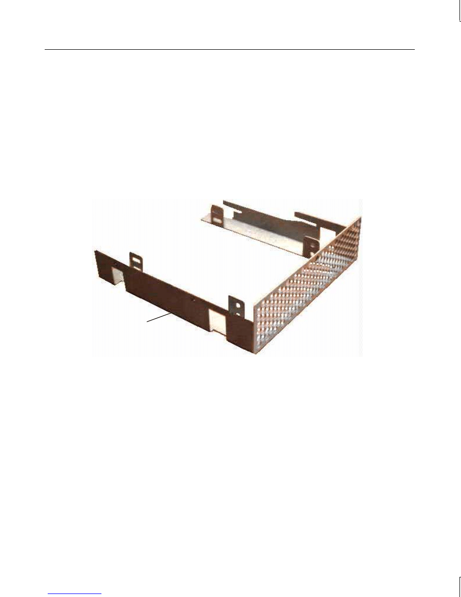
3. If removing a 5 1/4-inch wide device, remove the screws securing the peripheral guide
to the device, and remove the peripheral guide.
4. If removing a 3 1/2-inch wide device, remove the screws securing the device to the
optional disk bracket, and remove the device.
Optional Disk Bracket
Peripheral
guide
Tabs
Screws
manuals search engine
14
To install a new device in the optional device bay:
1. Disable SCSI termination and set the SCSI ID. Refer to the documentation delivered
with the device for more information.
2. Remove the screws securing the optional disk bracket to the right side of the chassis,
and slide the optional disk bracket forward and out of the base unit. Refer to the
previous figure.
3. If mounting a 5 1/4-inch wide device, remove the screws securing the peripheral guide
to the left side of the optional disk bracket, and remove the peripheral guide. Refer to
the following figure.
Secure the peripheral guide to the left side of the device using the screws provided.
Screws
Peripheral Guide
Optional Disk Bracket
4. If mounting a 3 1/2-inch wide device, place the device in the optional disk bracket.
Secure the device to the tabs using the screws provided. Refer to the previous figures.
5. Slide the device into the base unit from the front.
6. Secure the device to the device bay by installing screws to the right side of the chassis.
Refer to the previous figures.
7. Attach the cables to the device. Refer to the documentation delivered with the device for
more information.
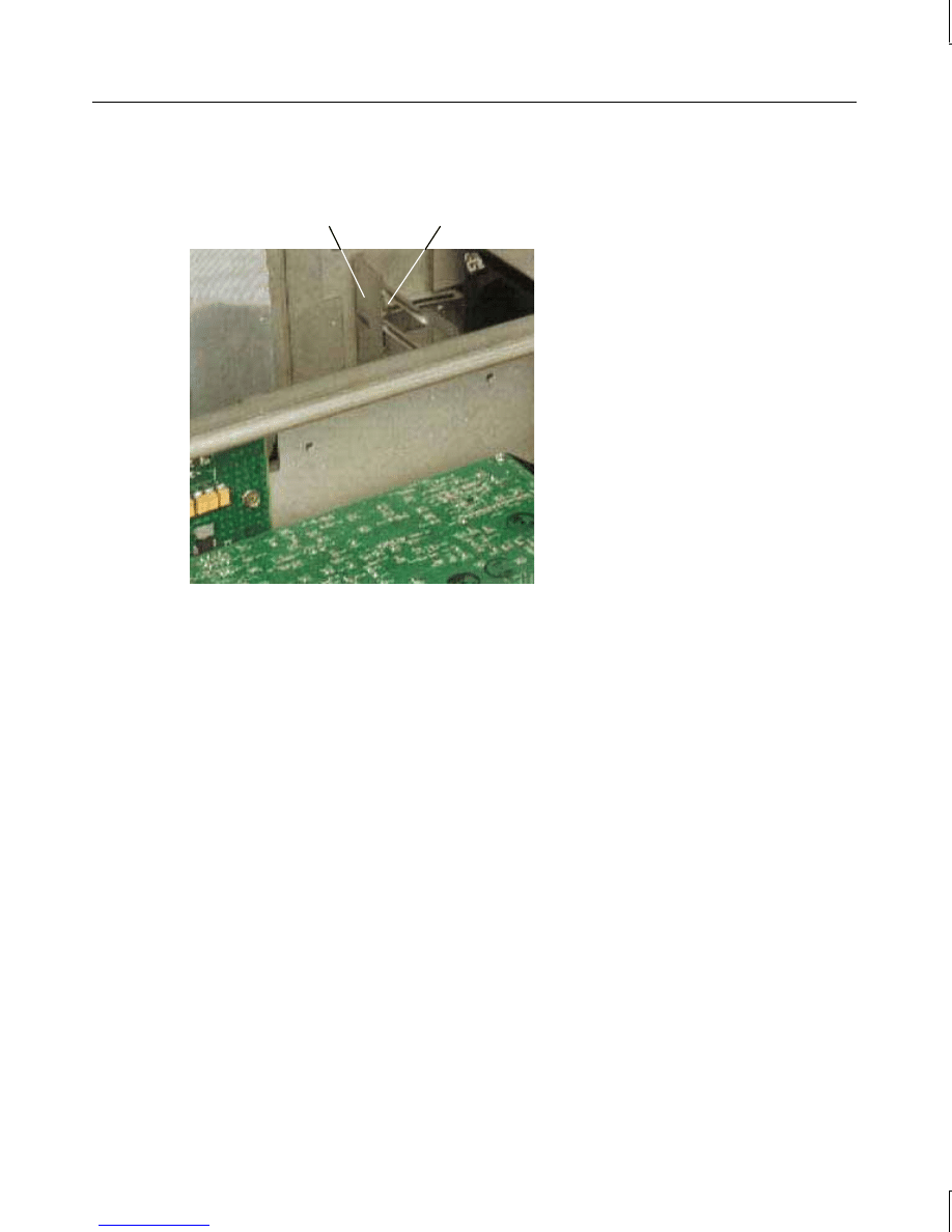
System Hard Disk Drives
The system hard disk drives are located in the system hard disk drive bay, between the power
supply and the riser card, near the rear panel. In a desktop system, this bay can house two 1-
inch drives, or one 1.6-inch drive.
To remove the desktop system hard disk drives:
1. Disconnect the cables from the hard disk drives, then remove the drives and the support
bracket; set them on a flat antistatic surface.
2. Remove the screws securing the hard disk drives to the bracket. Leave the grommets in
the bracket. Refer to the following figure.
manuals search engine
15
Grommets
Tabs
To remove the deskside system hard disk drive:
1. Disconnect the cables and remove the screws shown in the following figure from the
hard disk drive.
Power Cable
Chassis Screw
SCSI Cable
Bracket Screws
manuals search engine
16
2. Pull the drive forward and lift it out of the base unit, then set the drive on a flat antistatic
surface.
3. Remove the bracket screws that secure the drive to the bracket.
To install new hard disk drives:
1. Disable SCSI termination and set the SCSI ID. Refer to the documentation delivered
with the drive for instructions.
2. Secure the new drives to the support bracket using the screws removed previously.
3. Attach the cables to the new drives. The SCSI cable is keyed to ensure proper insertion,
so that the red stripe (pin 1) is adjacent to the power connector.
4. Install the drives and bracket into the base unit, inserting the tabs into the slots.
5. In a deskside system, secure the drive to the chassis by installing the chassis screw.
Peripheral
Brace
System Hard
Disk Drive Bracket
SCSI Cable
System Hard
Disk Drive
6. After closing the base unit and restarting the system, partition and format the system
hard disk drives as described in the operating system documentation, if necessary.
manuals search engine
17
Auxiliary Hard Disk Drives (Deskside)
Auxiliary hard disk drives are located in the bays above the CD-ROM drive.
To remove an auxiliary hard disk drive:
1. Disconnect the power and SCSI cables from the hard disk drive.
2. Remove the screws holding the drive to the chassis.
3. Slide the disk drive assembly out of the base unit.
4. Remove the screws attaching the hard disk drive to the bracket.
Bracket
To install a new auxiliary hard disk drive:
1. Disable SCSI termination and set the SCSI ID. Refer to the documentation delivered
with the device for details.
2. Secure the new drive to the bracket using the screws removed previously.
3. Slide the drive assembly into the chassis; then secure it to the chassis with the screws
removed previously.
4. Attach the cables to the new disk drive. The SCSI cable is keyed to ensure proper
insertion. The red stripe (pin 1) must be adjacent to the power connector.
5. After closing the base unit and restarting the system, partition and format the system
hard disk drive as described in the operating system documentation.
manuals search engine


19
3
Replacing System Components
This chapter describes replacing the following components of the TD-x20, TD-x25,
TDZ-x20, and TDZ-x25 workstation:
u
SCSI termination card (desktop)
u
Riser card
u
Option board fans (deskside)
u
System hard disk drive fan (deskside)
u
Processor module
u
System board
u
Power supply
u
CMOS/clock battery
You will need the following tools to service the system:
u
Quarter-inch nutdriver
u
No. 1 Phillips screwdriver
u
No. 2 Phillips screwdriver
u
Three-sixteenth-inch nutdriver
u
Five-sixteenth-inch or 8 mm nutdriver
u
Small single-slot screwdriver
Open the base unit, take precautions against electrostatic discharge, and attach an antistatic
wrist strap as described in Chapter 1, “Opening and Closing the Base Unit,” before replacing
any parts. After replacing system parts, close the base unit as described in Chapter 1.
CAUTION
The parts inside the base unit are designed to fit within very tight tolerances. Some force is
required to remove or insert parts. However, if you cannot remove or install a part properly,
ensure that there are no obstructions hindering the part.
NOTE
“Right side” and “left side” are as seen from the front of the base unit.
manuals search engine
20
SCSI Termination Card (Desktop)
The SCSI termination card terminates the internal SCSI cable chain. If external SCSI
devices are connected, the card disables termination and acts as a pass-through external
SCSI connector.
To remove the SCSI termination card:
1. Disconnect the external SCSI cable from the external SCSI port.
2. Remove the screws securing the external SCSI port to the back panel.
3. Note how the card is attached. Slide the card out of the chassis and disconnect the SCSI
cable.
SCSI Cable
SCSI Termination
Card
External SCSI Port
To install a SCSI termination card:
1. Connect the internal SCSI cable to the card.
2. Insert the card into the chassis and mount the external SCSI port to the back panel using
the screws removed previously.
3. After closing the base unit, connect the external SCSI cable to the external SCSI port.
manuals search engine
21
Riser Card
To remove the desktop riser card:
1. Remove the floppy disk drive as described previously in Chapter 2, “Maintaining System
Devices,” leaving the cables attached.
2. Remove the system hard disk drives as described previously in Chapter 2, “Maintaining
System Devices,” leaving the cables attached.
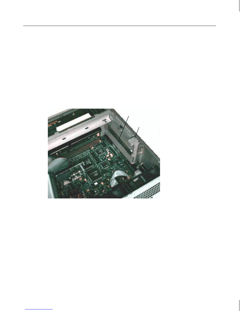
3. Remove all boards connected to the riser card. Note the position of each board as you
remove it. To remove the ISA boards in the ISA I/O panel, remove the I/O lock bracket
(note orientation) shown in the following figure.
Blanking Plate
I/O Lock
Bracket
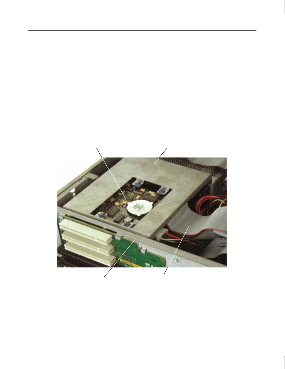
4. Lift up and remove the peripheral brace shown in the following figure.
5. Disengage the riser card from the system board, and remove the card from the base unit.
manuals search engine
22
Riser Card
To remove the deskside riser card:
1. Remove the PCI access panel as described previously in Chapter 2, “Maintaining System
Devices.”
2. Remove the PCI boards connected to the riser card as described previously in Chapter 2,
“Maintaining System Devices.”
3. If ISA option boards are installed, disconnect the SCSI cable and power cables from the
top of the riser card, and remove the ISA I/O lock bracket. Refer to the following figure.
ISA I/O Lock
Bracket
SCSI Cable
Connector
Power Cable
Connector
manuals search engine
23
4. Remove the screw on the pivoting ISA board guide, shown in the following figure.
5. Remove the ISA boards connected to the riser card. Note the position of each board.
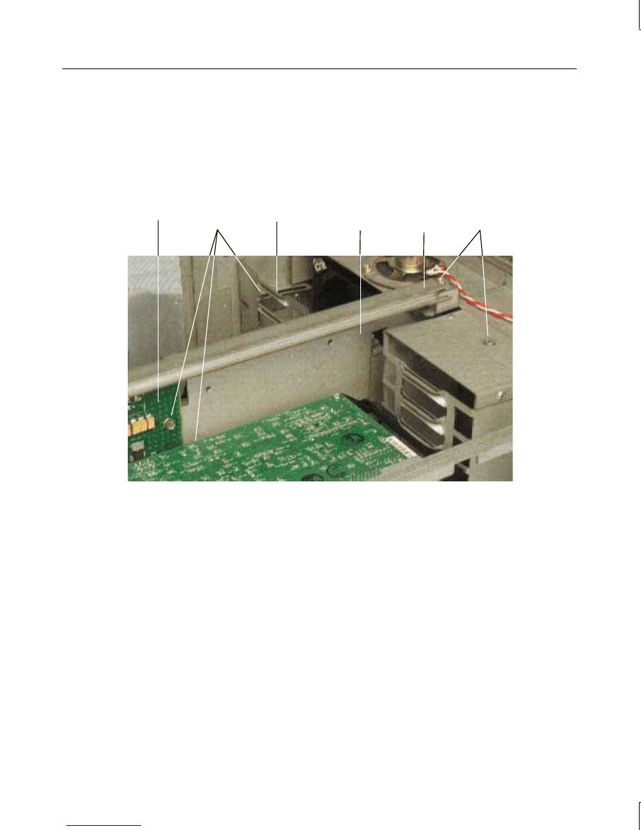
6. Remove the screws shown in the following figure.
7. Slide the peripheral brace to the back of the base unit and remove it; then remove the air
baffle.
Riser
Card
ISA Board
Guide
Peripheral
Brace
Air Baffle
Screws
Screws
8. Disengage the riser card from the system board, and remove the card from the base unit.
To install a new riser card:
1. Insert the riser card into its system board slot, pushing firmly over the center of the PCI
connectors to ensure it seats completely.
CAUTION
Do not rock the riser card back and forth; pins inside the connector may be damaged as a
result. Press firmly so the card connector slides evenly into the slot.
2. Replace the peripheral brace. In a deskside system, do not tighten the pivoting ISA
board guide until the ISA boards have been installed.
3. Replace the option boards connected to the riser card. Connect any external cables
attached to the boards. Boards must be installed in the same slots from which they were
removed.
4. In a deskside system, replace the ISA I/O lock bracket and the PCI access panel.
5. Connect the SCSI and power cables to the riser card.
manuals search engine
24
6. In a desktop system, replace the system hard disk drives and the floppy disk drive.
Option Board Fans (Deskside)
To remove the option board fans:
1. Remove the peripheral brace, as described previously in Chapter 2, “Maintaining
System Devices.”
2. Disconnect the power cables from the system board.
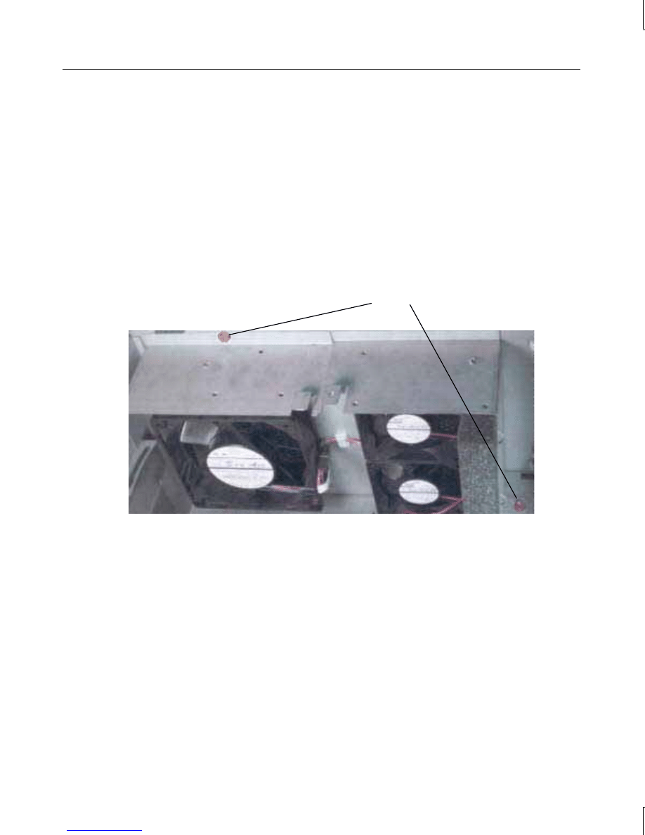
3. The option board fans are removed as a single, self-contained assembly. Remove the fan
assembly screws shown in the following figure; then remove the fan assembly.
Screws
To install a new option board fan:
1. The option board fans are installed as a single, self-contained assembly. Install the new
fan assembly into the chassis and connect the power cables to the system board.
2. Replace the peripheral brace.
System Hard Disk Drive Fan (Deskside)
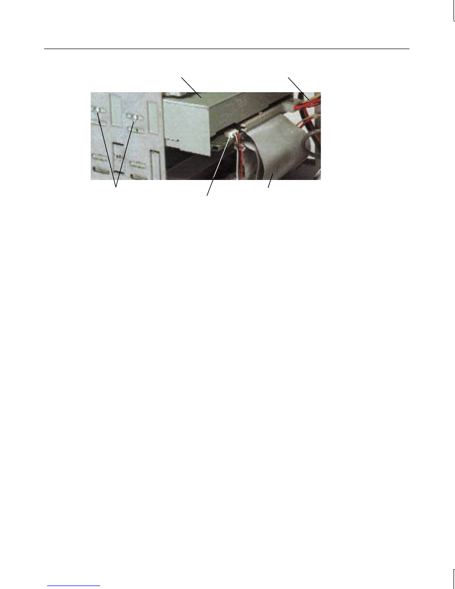
A small fan beneath the power supply provides cooling to the system hard disk drives.
To remove the system hard disk drive fan:
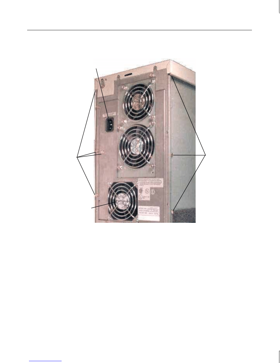
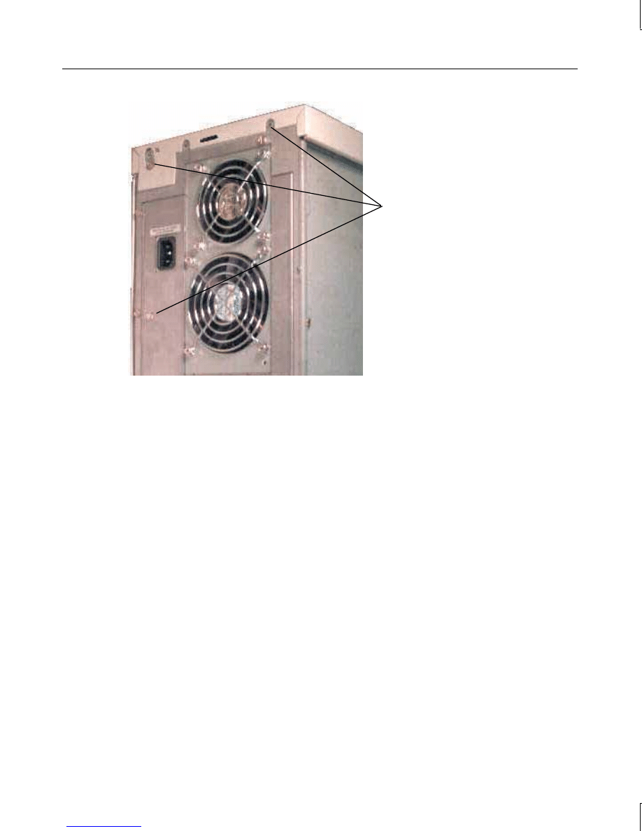
1. Remove the screws shown in the following figure from the back cover. Pull on the side
of the cover opposite the AC receptacle to disengage it.
manuals search engine
25
CAUTION
Do not remove the two screws at the top of the chassis. The power supply could fall, causing
damage inside the base unit.
Screws
Screws
System Hard
Disk Drive Fan
AC Receptacle
2. Disconnect the fan power cable from the system board.
3. Remove the fan from the back panel.
To install a new system hard disk drive fan:
1. Attach the new fan to the back panel.
2. Connect the fan power cable to the system board.
3. Replace the back and side panels and the top cover, then close the base unit.
manuals search engine

26
Processor Module
The Pentium Pro and Pentium II processors are housed in plastic processor modules, which
have heat sinks attached to one side. When a Pentium II module is installed into an S1 slot,
the heat sinks are supported at the bottom by a black plastic bar, which runs between the two
bottom-most rows of heat sink fins. The support bar is connected to a support assembly via
four posts.
To remove a processor module:
1. In a desktop system, remove the floppy disk drive as described in Chapter 2,
“Maintaining System Devices.”
2. Remove the peripheral brace, as described previously in “Replacing the Riser Card.”
NOTE
Pentium Pro processor modules do not require heat sink support.
3. Remove the top section of the heat sink support, if necessary. The plastic support bar has
a tab on each end. Press both tabs inward, towards each other, while using a pulling
motion to pull the bar away from the heat sink fins. The support assembly is
permanently connected to the system board, and need not be removed. Refer to the
following figure.
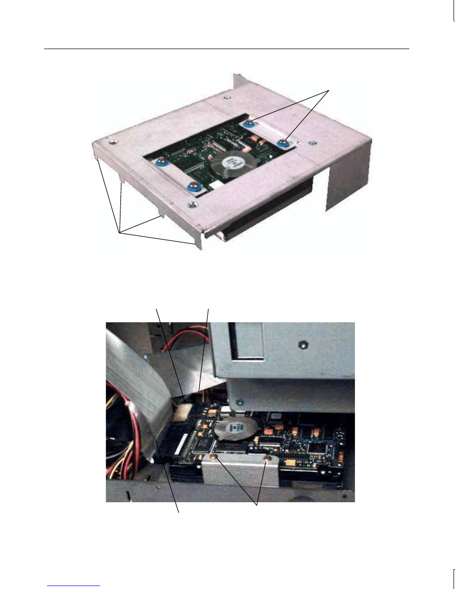
4. Remove the processor module. Grasp both tabs on the top corners of the processor
module and press them inward, towards each other. Then pull the entire module
upward, keeping the tabs pressed inward. The heat sinks are permanently connected to
the module, and need not be removed.
If replacing a Pentium Pro processor module with a Pentium II processor module:
1. Remove the jumper from J19, and place it on jumper J39. Refer to the following figure.
2. Install the heat sink support assembly to the system board. The assembly snaps into
place in two of the indicated holes. Refer to the following figure.
manuals search engine
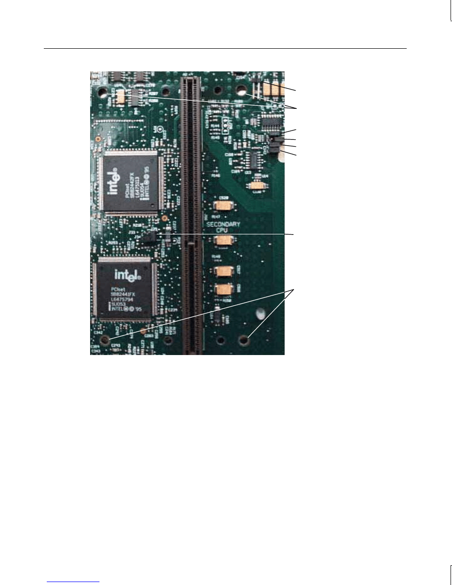
27
Voltage
Jumper J39
Voltage Jumper J19
J48
Frequency
J47
Jumpers
J50
J49
Heatsink Support
holes
Heatsink Support
holes
To install a new processor module:
1. If necessary, set the frequency for the new processor by adjusting jumpers J47 through
J50. Refer to Chapter 5, “System Board Jumpers,” for more information.
2. Align the new processor module over the S1 slot and firmly press it down into the slot.
3. If necessary, replace the top section of the heat sink support. Gently push the plastic
support bar toward the four posts on the heat sink support assembly, until the bar snaps
into place.
4. Re-install the peripheral brace and, if necessary, the floppy disk drive.
manuals search engine
28
System Board
CAUTION
The system board is extremely sensitive to static electricity. To prevent serious damage to
the system board, wear the antistatic wrist strap while performing the following steps. Do not
open the antistatic bag containing the system board until instructed.
To remove the system board:
1. In a desktop system, remove the floppy disk drive and system hard disk drives as
described previously in Chapter 2, “Maintaining System Devices.”
2. Remove the peripheral brace, as described previously in “Replacing the Riser Card.”
3. Remove the riser card, as described previously in “Replacing the Riser Card.”
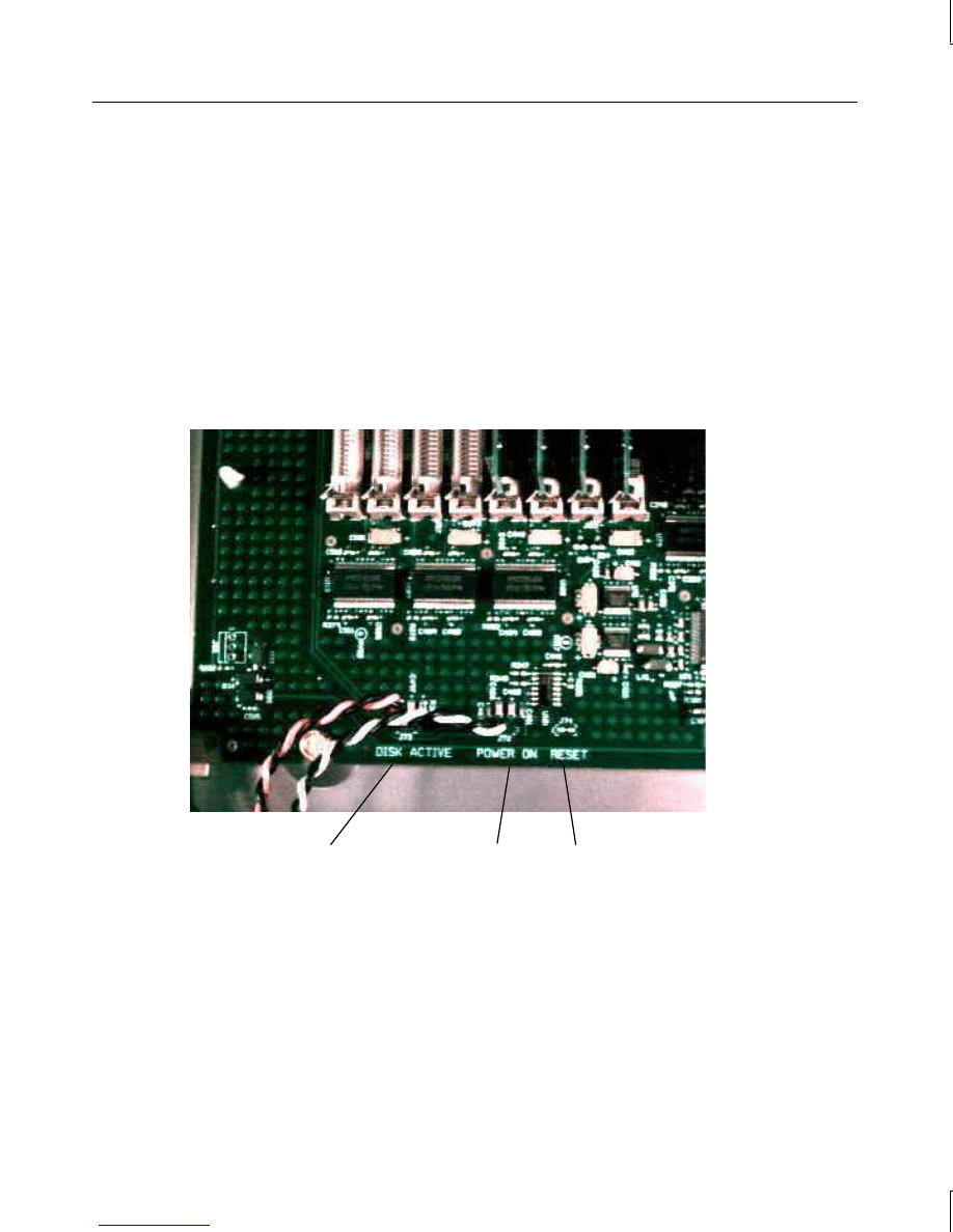
Reset Cable
Connector
Disk Activity LED
Cable Connector
Power On LED
Cable Connector
4. Note the orientation of the Reset, Disk Activity LED, and Power On LED cables; then
disconnect the LED and Reset cables from the system board.
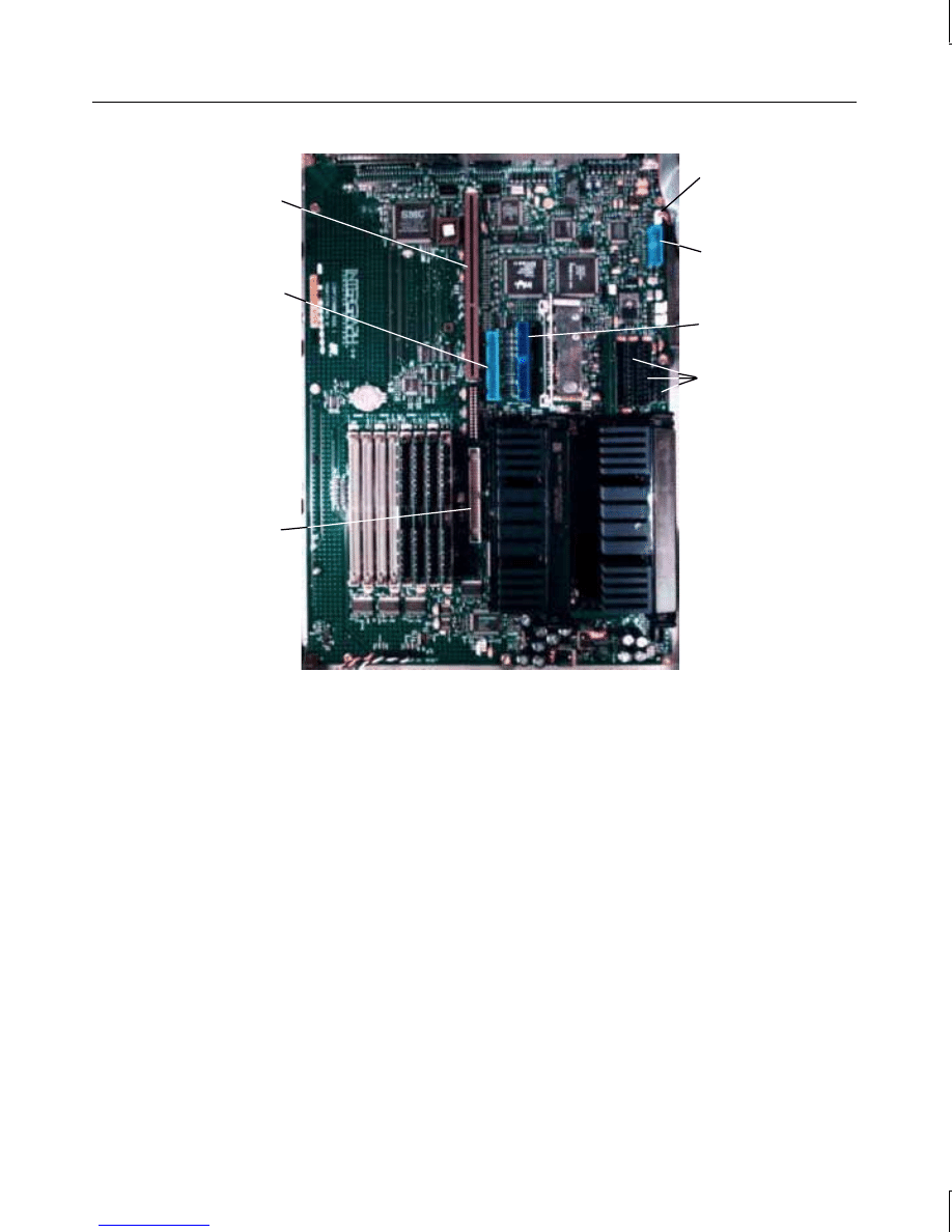
5. Disconnect all other cables from the system board. The following figure shows the cable
connector locations.
manuals search engine
29
Power Cable
Connectors
MIDI/Game
Cable
Connector
SCSI Cable
Connector
CD-ROM
Audio Cable
Connector
EIDE Cable
Connector
Riser Card
Connector
Floppy Disk
Drive Cable
Connector
6. Disconnect the cables from the external ports.
7. Remove the jackscrews from the video, parallel, and serial ports.
8. Remove the hex nuts from the audio jacks.
9. Remove the eight grounding screws from the system board.
10. Slide the system board to the front of the base unit.
11. Lift the board and remove it from the base unit. Set the board on a flat antistatic
surface.
12. Remove the new system board from the antistatic bag and place it on a flat antistatic
surface.
13. Remove the SIMMs from the old system board and install them onto the new one in the
same configuration.
manuals search engine

30
To install a new system board:
The new system board should have the SIMMs installed before placing it into the base unit.
1. Lower the new system board into the base unit. Ensure the standoff lines up with the
hole in the chassis. Slide the system board to the back of the base unit so the external
ports fit into the back panel.
2. Install the eight grounding screws.
3. Install the hex nuts onto the audio jacks.
4. Install the jackscrews onto the video, parallel, and serial ports.
5. Connect the MIDI/Game and CD-ROM audio cables to the system board.
6. Connect the system power cables to the power cable connectors on the system board.
The connectors are labeled with the corresponding system board connector.
7. Connect the LED and Reset cables to the system board.
NOTE
The orange wire for the disk activity LED cable must connect to pin 1. The white wire for the
power on LED cable must also connect to pin 1. The orientation of the reset cable wires is
not critical.
8. Install the riser card and the peripheral brace.
9. Replace the PCI option board support bracket, option boards, and their external cables.
NOTE
Boards they must be placed in the same slots from which they were removed. Also replace
the I/O lock bracket for the ISA boards on side two of the riser card.
10. Install the floppy disk drive; then connect the power cable and data cables to the system
board.
11. Install the floppy disk drive and system hard disk drives, and connect the SCSI cable to
the system board.
Power Supply
CAUTION
Purchase replacement power supplies from Intergraph to ensure proper specifications are
met and to guarantee safety.
WARNING
In a desktop system, set the AC voltage switch on the back of the power supply to the
correct voltage for your location, or the power supply will be irreparably damaged
when power is applied. If you do not know the voltage range, call your local utilities
company for assistance.
manuals search engine

31
To remove the power supply from a desktop system:
1. Remove the AC power cord from the back of the base unit.
2. Remove the SCSI termination card as described previously in “SCSI Termination Card
(Desktop).” It is not necessary to disconnect the card from the SCSI cable.
3. Remove the system disk drives as described previously in Chapter 2, “Maintaining
System Devices.”
4. Disconnect the power cables from the floppy disk drive, CD-ROM drive, and hard disk
drives.
5. Disconnect the system power cables from the power cable connectors on the system
board.
6. Open the clip that secures the bundle of power cables. Remove the audio cable
(connecting the CD-ROM drive to the system board) from the power cable bundle.
7. Remove the screws securing the power supply to the back of the base unit.
8. Slide the power supply to the front and remove it from the base unit.
9. Remove the power switch cable and grounding wire from the chassis.
To remove the power supply from a deskside system:
1. Remove the AC power cord from the back of the base unit.
2. When opening the base unit, remove the side panels and back panel.
3. Disconnect the power cables from the riser card, hard disk drives, floppy disk drive, and
CD-ROM drive.
4. Disconnect the system power cables from the power cable connectors on the system
board.
5. Open the clip that secures the bundle of power cables. Remove the audio cable
(connecting the CD-ROM drive to the system board) from the power cable bundle.
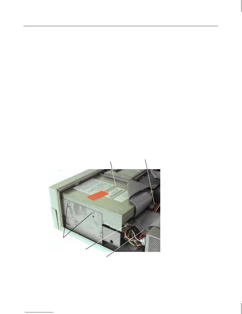
6. Remove the screws securing the power supply to the back of the base unit. Refer to the
following figure.
CAUTION
Support the bottom of the power supply with your hand as you remove the screws.
Otherwise, the power supply could fall and cause damage inside the base unit.
manuals search engine
32
Screws
7. Push the power supply out the side of the base unit.
8. Remove the power switch cable and grounding wire from the chassis.
To install a new power supply:
1. Remove the new power supply from its packaging. On a desktop system, set the AC
voltage switch on the back of the new power supply to the correct voltage for your
location.
2. Slide the new power supply into place in the base unit. Mount the power supply using
the screws removed previously.
3. Mount the power switch cable and grounding wire to the chassis.
4. Connect the system power cables to the power cable connectors on the system board.
5. In a deskside system, slide the power cable bundle through the opening; then connect
the main power cable to the riser card.
6. Connect the remaining power cables to the hard disk drives, CD-ROM drive, and floppy
disk drive.
7. Secure the clip around the power cable bundle.
8. In a desktop system, mount the SCSI termination card to the chassis.
9. In a desktop system, replace the system hard disk drives and connect the power cable.
10. Connect the AC power cord to the back of the base unit.
manuals search engine
33
CMOS/Clock Battery
WARNING
There is a danger of explosion if the battery is incorrectly replaced. Replace the
battery with the same or equivalent type only, as recommended by the manufacturer.
Dispose of used batteries according to the manufacturer’s instructions.
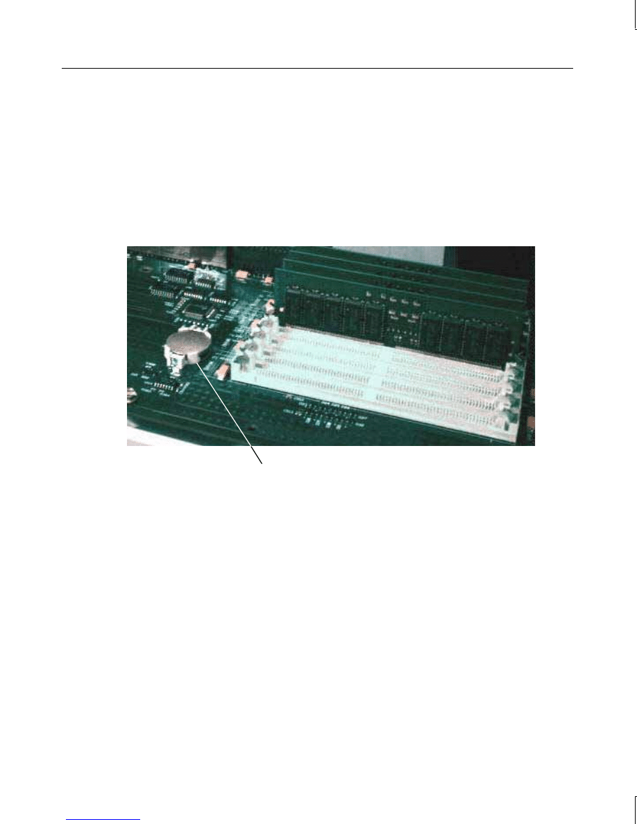
To replace the CMOS/clock battery:
1. The battery is located on the system board, as shown in the following figure. Remove
any option boards that interfere with access to the battery.
Battery
2. Carefully remove the discharged battery by grasping it firmly and lifting upward.
3. Install the new battery in the same orientation as the discharged battery.
4. Replace the option boards that you removed in step 1 above.
manuals search engine


35
4
Upgrading the System
This chapter describes upgrading your TD-x20, TD-x25, TDZ-x20, or TDZ-x25 workstation
by adding more memory, internal or external SCSI devices, and option boards.
Attach an antistatic wrist strap as described in Chapter 1, “Opening and Closing the Base
Unit,” before opening the base unit.
Adding Main Memory
Single inline memory modules (SIMMs) must meet the following specifications:
Height
Up to 1.4 inches high
Type
72-pin, single- or double-sided EDO SIMMs
Specifications
5 volt, 60 ns, 36 and 32 bit, tin-plated edge finger contacts
NOTE
System memory modules available from Intergraph have been certified for use with
Intergraph computers at extremes of temperature and system load to ensure reliable
performance. System memory modules available from other vendors may function
improperly or unreliably in your Intergraph computer.
To avoid damaging the SIMMs and voiding the warranty, take the following precautions .
u
Do not bend, twist, drop, or otherwise handle the SIMMs carelessly.
u
Do not expose the SIMMs to moisture or extreme temperatures.
u
Do not remove the SIMMs from the antistatic bag until instructed.
Follow these SIMM population rules to correctly install the SIMMs.
u
Each bank has two slots. Fill both slots in a bank.
u
Use the same size SIMM in both slots in a bank.
u
Install SIMMs one bank at a time, beginning with bank 0 and ending with bank 3.
u
After adding or replacing SIMMs, restart the computer. The new memory configuration
is detected automatically.
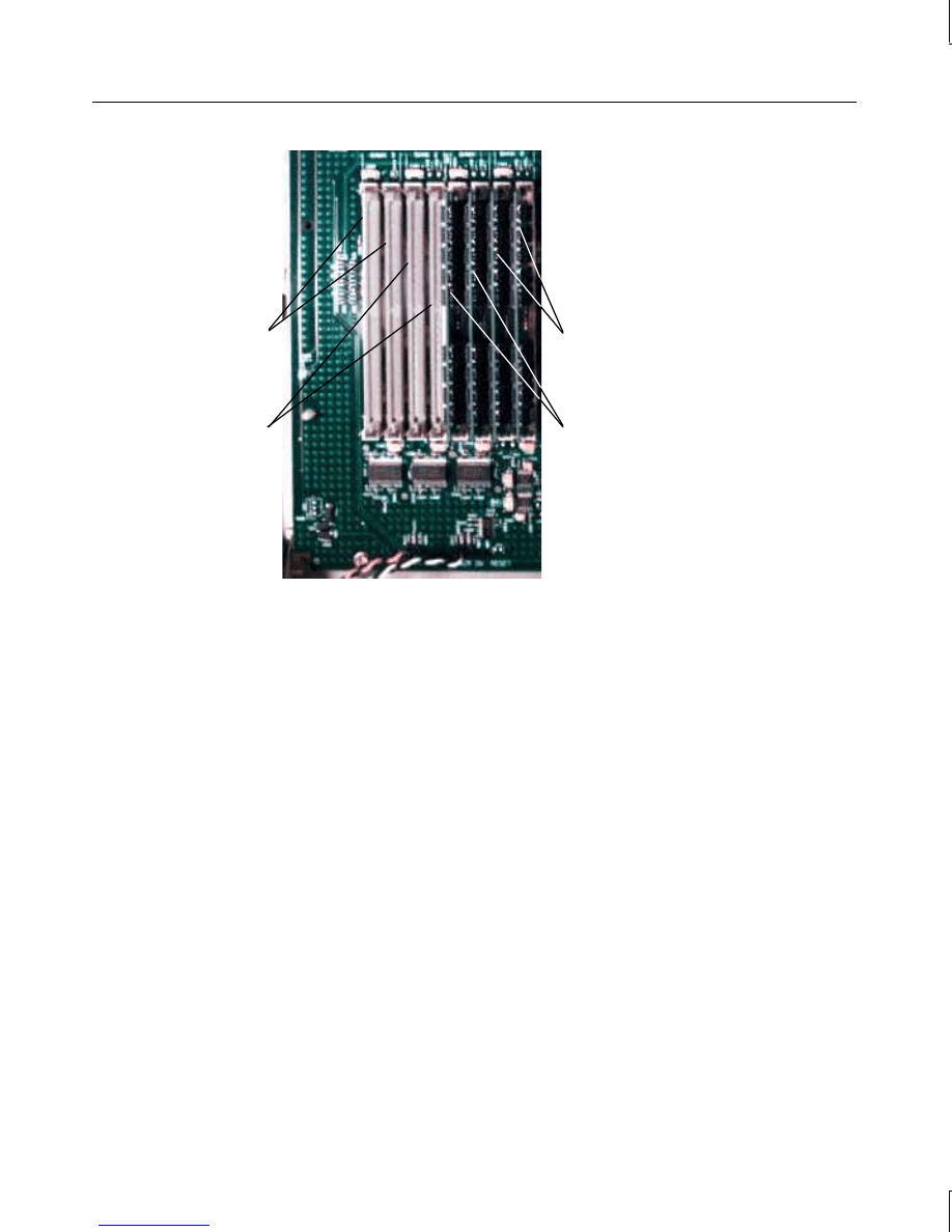
To install a memory upgrade:
1. Remove any option boards that interfere with access to the SIMM sockets.
2. Remove the existing SIMMs from their sockets before adding new ones. Refer to the
following figure.
manuals search engine
36
Socket 3
Socket 2
Socket 0
Socket 1
3. Remove the SIMMs from their antistatic bag.
4. Position the SIMM in the next available socket so that the notch faces the front of the
base unit.
5. Insert the SIMM at a 60 degree angle, pressing it firmly into the socket.
6. Push on the top edge of the SIMM until it snaps into the metal clips and locks into the
vertical position. The socket tabs must fit inside the mounting holes of the SIMM.
CAUTION
Do not use a rocking motion as you install the memory module. Doing so might damage the
module, the socket, or both.
7. Repeat steps 5 through 7 for each SIMM.
8. Replace the option boards that you removed in step 1 above.
9. After you close the base unit, restart the system. The new memory is recognized
automatically.
Adding Internal SCSI Devices
Desktop systems are equipped with an Ultra SCSI controller for all SCSI devices.
u
You can install internal Ultra SCSI devices, or devices controlled from an expansion
card, in the device bays located on the right front side of the base unit of a desktop
system. The device must be 1.6 inches high or less to fit in these bays.
manuals search engine

37
u
You can install a replacement or a second SCSI hard disk drive into the system hard
disk drive bracket between the riser card and power supply. If the hard disk drive is
more than 1 inch high, you will not be able to install a second hard disk drive into the
system hard disk drive bracket, nor will you be able to use ISA slot 1. If you install a
second hard disk drive in the system hard disk drive bracket, you will not be able to use
ISA slot 1. If you install a non-Ultra SCSI device, data transfer rates are limited to the
device’s speed.
Deskside systems are equipped with an Ultra Wide SCSI controller for internal SCSI
devices. The internal device bays are located above the floppy disk drive bay. You can
install internal Ultra Wide SCSI devices, or devices controlled from an expansion card, in
the device bays. The device bays are designed to accommodate 1.6-inch high devices; if a
device is more than one 1.6-inch high, the bay underneath must be left empty. If you install
a non-Ultra Wide SCSI device, data transfer rates are limited to the device’s speed.
CAUTION
Connecting a non-compliant SCSI-1 device to a TD-x20, TD-x25, TDZ-x20, or TDZ-x25
workstation may cause your system to stop working, or lead to other unpredictable results.
To install an internal SCSI device:
NOTE
Refer to Chapter 2, “Maintaining System Devices,” for information about removing and
replacing devices in the system, and for information on installing a device in the optional
device bay on the desktop system.
1. If a device already occupies the location in which you are adding the new device, remove
the existing device. If installing the device into an empty drive bay, remove the support
or slide bracket from the drive bay.
2. Mount the device to the support or slide bracket, if necessary.
3. If you are installing the device into one of the forward device bays in a desktop system,
slide the device through the faceplate and secure it to the chassis.
4. If installing hard disk drives into the system hard disk drive bracket in a desktop system,
replace the bracket, ensuring the bracket tabs engage the slots on the peripheral brace.
NOTE
ISA Slot 1 can be used only if a single system hard disk drive is installed, and if it is less than
1.6-inches in height.
5. Connect the SCSI cable and power cable to the device. The SCSI cable is keyed to
ensure proper insertion, so that the red stripe (pin 1) is adjacent to the power connector.
manuals search engine
38
Peripheral
Brace
Power
Connector
SCSI Cable
Red Stripe
6. After closing the base unit, install the device drivers and configure the device according
to the vendor’s instructions, if necessary.
Adding External SCSI Devices
Desktop systems are equipped with an Ultra SCSI controller for all SCSI devices. If you
install a non-Ultra SCSI device, data transfer rates are limited to the device’s speed.
Deskside systems are equipped with a separate Ultra SCSI controller for external SCSI
devices. If you install a non-Ultra SCSI device, data transfer rates are limited to the device’s
speed.
CAUTION
Connecting a non-compliant SCSI-1 device to a TD-x20, TD-x25, TDZ-x20, or TDZ-x25
system may cause your system to stop working, or lead to other unpredictable results.
You can add up to five external single-ended SCSI devices to a desktop workstation, and up
to seven external single-ended SCSI devices to a deskside workstation. The total length of
the external SCSI cables depends on the number of devices connected to the SCSI adapter.
manuals search engine

39
The total length must not exceed the following:
Devices
SCSI-1
SCSI-2
Ultra SCSI
1 to 4
6 meters
3 meters
3 meters
5 to 8
3 meters
3 meters
1.5 meters
NOTE
You must count the controller as one device.
When calculating the total length of the SCSI cables connected to the SCSI adapter, use the
following estimates where appropriate:
SCSI cabling inside a desktop workstation
101.6 mm
SCSI cabling inside each external device
203.2 mm
NOTE
The last external device on the SCSI cable chain must supply active termination. All other
external devices must have SCSI termination disabled or removed.
To install an external SCSI device:
1. Set the device’s SCSI ID to an unused number and enable or disable the device’s SCSI
termination according to the note above and the vendor’s instructions.
2. Connect one end of the SCSI cable to the SCSI port on the back of the base unit. If
other external devices are installed, connect the SCSI cable to the available SCSI port on
the last device on the SCSI cable chain.
3. Connect the new SCSI device to the other end of the SCSI cable.
4. If necessary, install the device drivers and configure the device according to the vendor’s
instructions.
Adding Option Boards
This section briefly describes the differences between Peripheral Component Interconnect
(PCI) and Industry Standard Architecture (ISA) option boards. Instructions are also provided
for installing option boards on the riser card.
manuals search engine
40
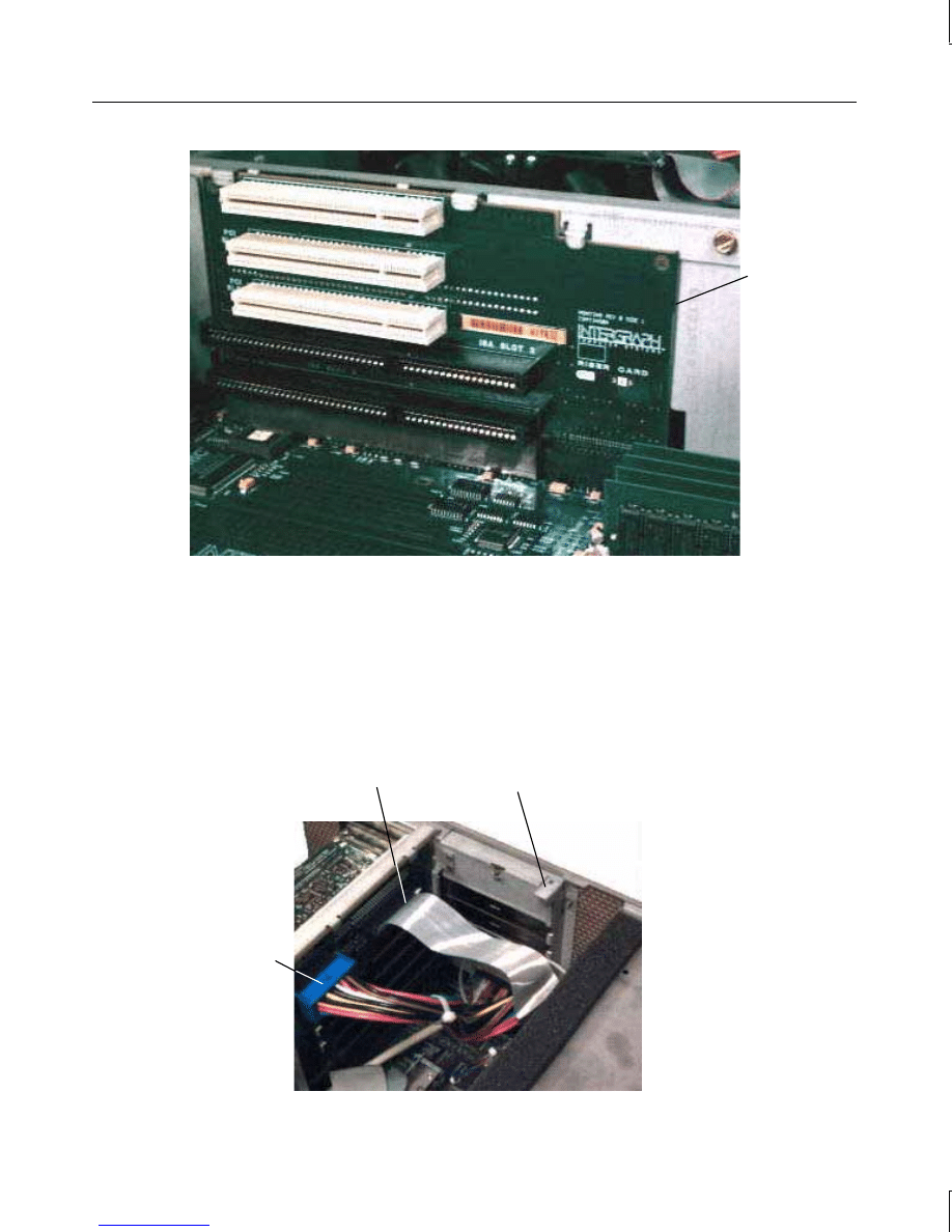
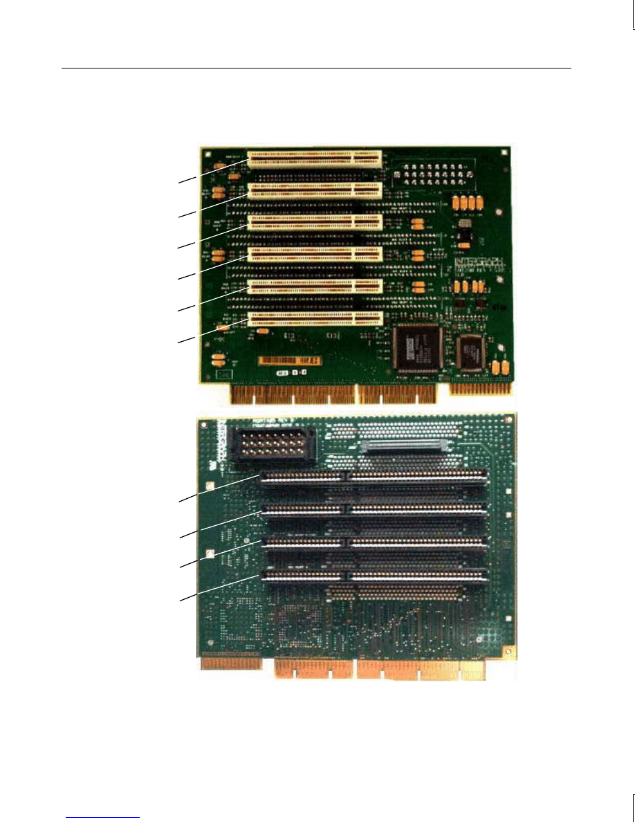
In desktop systems, PCI boards connect to side one only; ISA boards connect to each side. If
a PCI board is not installed in PCI slot 3, then a second ISA board connects to ISA slot 2 on
side one. The following figure shows the slots on the desktop riser card.
PCI Slot 1
Side 1
ISA
Slot 2
ISA
Slot 3
PCI Slot 3
PCI Slot 2
Side 2
ISA Slot 1
manuals search engine
41
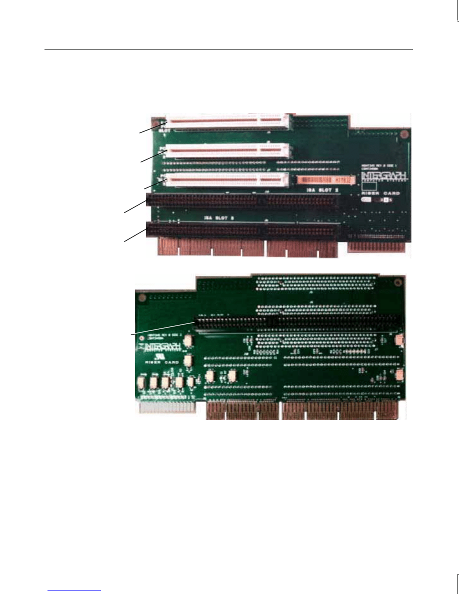
In deskside systems, PCI boards connect to Side 1 of the riser card; ISA boards connect to
Side 2. The following figure shows the slots on the deskside riser card.
Side 1
PCI Slot 1
PCI Slot 2
PCI Slot 3
PCI Slot 4
PCI Slot 5
PCI Slot 6
Side 2
ISA Slot 4
ISA Slot 3
ISA Slot 2
ISA Slot 1
manuals search engine

42
Primary PCI Slots
Some PCI option boards must be installed in a primary PCI slot. Refer to the documentation
delivered with the option board to determine if it must be installed in a primary PCI slot.
The following are the primary PCI slots.
Desktop systems:
PCI Slots 1, 2, 3
Deskside systems:
PCI Slots 5, 6
PCI Option Boards
PCI boards do not require manual system configuration when installing the board. The
system BIOS detects the board’s presence during startup and reads information from the
board’s configuration registers to assign the necessary system resources.
Setting jumpers on PCI IDE controller boards:
1. To install a PCI IDE controller board, you must first set the jumpers on the controller
board to coordinate the primary IDE channel with IRQ14. If the controller board is a
dual channel board, set the jumpers to coordinate the secondary IDE channel with
IRQ15 as well. Use the guide below when setting the jumpers.
Desktop Systems
IRQ14
IRQ15
PCI Slot 1
INT A
INT B
PCI Slot 2
INT D
INT A
PCI Slot 3
INT C
INT D
Deskside Systems
IRQ14
IRQ15
PCI Slot 5
INT A
INT B
PCI Slot 6
INT D
INT A
NOTE
A PCI IDE controller board must be installed in a primary PCI slot.
2.
Install the controller board according to the instructions that follow.
To install PCI option boards:
1. Remove the blanking plate from an available PCI slot.
2. Install the PCI board. Press firmly to ensure the board seats completely into the riser
card connector.
manuals search engine
43
3. Mount the board to the chassis using the screw removed in step 1 above.
4. After closing the base unit, restart the system. The new PCI board is recognized and
configured automatically.
ISA Option Boards
ISA boards require that specific system resources be reserved for their use. You can define
and reserve these resources automatically if your operating system supports Plug-and-Play.
Otherwise you can define and reserve these resources using the Setup options in BIOS Setup.
Refer to the System Setup guide for more information.
To install an ISA board:
NOTE
ISA Slot 1 can be used only if a single system hard disk drive is installed, and if it is less than
1.6-inches in height.
1. If installing the board onto side one of the riser card, remove the blanking plate from the
appropriate slot.
2. If installing the board to side two of the riser card, do the following:
In a desktop system, remove the system hard disk drive.
In a deskside system, disconnect the intervening cables from the riser card.
Remove the I/O lock bracket and the blanking plate, shown in the following figure.
I/O Lock
Bracket
Blanking Plate
Desktop System
I/O Lock
Bracket
Deskside System
Blanking
Plate
manuals search engine
44
3. On a deskside system, loosen the screw to allow the pivoting ISA board guide to swing
toward the system fans, shown in the following figure.
ISA Board Guide
Screw
4. Install the option board. Press firmly to ensure the board seats completely in the slot.
5. Slide the pivoting ISA board guide over the edge of the ISA board; then, tighten the
screw.
6. Secure the board to the chassis with the screw, and install the I/O lock bracket.
NOTE
The I/O lock bracket installs in only one orientation.
7. Replace the system hard disk drives or reconnect the cables to the riser card, as
appropriate.
8. After closing the base unit, restart the system.
You may need to load device drivers to enable the new option board to operate. If so, refer to
the documentation provided with the option board.
manuals search engine

45
5
Hardware Information
This chapter lists system specifications, system model number information, and option board
slot assignments. It discusses the sound controller, DMA channels, Input/Output addresses,
memory address map, PCI to ISA Bus interrupt mapping, PCI bus configuration space, and
ISA Bus. The external port pinouts, system board connector pinouts, system board jumpers,
and power supply information are also described.
System Specifications
System BIOS
American Megatrends BIOS core 800
Processor(s)
Intel Pentium Pro and Pentium II
Host Bridge
82441FX PCI and Memory Controller (PMC) and 82442FX
Data Bus Accelerator (DBX). PCI bus compliant to PCI Bus
Specification revision 2.1
Graphics Accelerator
I3D100, I3D1000, Z13, Z25, V25, or Matrox Millennium II
Sound Controller
Crystal CS4236B, PC97 compliant
Ethernet Controller
Intel 82557 10/100BaseTX PCI with RJ45 connector
SCSI Controller
Adaptec AIC-7860 Ultra (deskside external port, desktop)
Adaptec AIC-7880 Ultra Wide (deskside internal port)
Peripheral Controller
Standard Microsystems FDC37C932
EIDE Controller
Intel 82371SB PCI/ISA IDE Xccelerator (PIIX3)
PCI-to-ISA Bridge
Intel 82371SB PCI/ISA IDE Xccelerator (PIIX3)
Universal Serial Bus Ports
12 MBit per second transfer rate
Mouse
Three button Microsoft IntelliMouse
Keyboard
PS/2, 104 key, multimedia with speakers
Base Unit Dimensions
Deskside: 463.4 mm x 483.7 mm x 102.9 mm
Desktop: 462.3 mm x 482.6 mm x 124.4 mm
Expansion Slots
Deskside: Six full-length PCI, four full-length ISA
Desktop: Two full-length PCI, one full-length PCI/ISA, two
half-length ISA
Power Supply
90-132 VAC or 180-264 VAC; 47-63 Hz input frequency
Deskside: 539 Watts, auto-ranging
TDZ desktop: 300 Watts, manual-ranging
TD desktop: 200 Watts, manual-ranging
manuals search engine

46
System Model Number
The model number on the back of the base unit identifies the system hardware configuration.
Individual digits are defined as follows:
Digit
Meaning
1: Series
U: Desktop system
W: Deskside system
2: Processor Type
H - 200 MHz Pentium Pro
J - Dual 200 MHz Pentium Pro
U - 266 MHz Pentium II
V - Dual 266 MHz Pentium II
2 - 300 MHz Pentium II
3 - Dual 300 MHz Pentium II
3. Graphics
0 - None
2 - Z13T with 16 MB
7: Millennium II with 4 MB RAM
D: Millennium II with 8 MB RAM
E: Millennium II with 12 MB RAM
Q - Z13
R - Z25
S - Z13GT with 32 MB
T - Z25GT with 64 MB
W - Intense 3D-100
Y - V25
Z - Intense 3D-1000
4: Chassis
0:
Workstation
5: Memory
0 - None
4 - 32 MB
6 - 64 MB
7 - 128 MB
9 - 256 MB
B - 512 MB
6: Peripheral Drives
0:
None
3:
CD-ROM drive
manuals search engine

47
Digit
Meaning
7: Disk Drives
0 - No hard drive
4 - 4 GB hard drive
9 - 9 GB hard drive
R - 4 GB 10 K RPM hard drive
S - 9 GB 10 K RPM hard drive
8: Operating System
2: Windows NT Workstation
9:
Solaris
9: Revision
Variable
Graphics Option Board Slot Assignments
Graphics option boards must be installed in specific PCI slots. Refer to the following chart
to determine where to install your option board.
Desktop System PCI Slot Assignments
Millennium II
Millennium II
Dual Screen
Slot 1
Slot 2
Graphics board
Slot 3
Graphics board
Graphics board
I3D1000
I3D1000
Dual Screen
I3D1000-G
I3D1000-G
Dual Screen
Slot 1
Geometry board
Geometry board
Slot 2
Graphics board
Graphics board
Graphics board
Graphics board
Slot 3
Graphics board
Graphics board
Z13
Z13-G
Z25
Z25-G
Slot 1
Geometry board
Geometry board
Slot 2
Graphics board
Graphics board
Graphics board
Graphics board
Slot 3
VGA board
VGA board
VGA board
VGA board
manuals search engine

48
V25
V25-G
Slot 1
Geometry board
Slot 2
Graphics board
Graphics board
Slot 3
VGA board
VGA board
Deskside System PCI Slot Assignments
Millennium II
Millennium II
Dual Screen
Slot 1
Slot 2
Slot 3
Slot 4
Graphics board
Slot 5
Graphics board
Graphics board
I3D1000
I3D1000
Dual Screen
I3D1000-G
I3D1000-G
Dual Screen
Slot 1
Slot 2
Slot 3
Graphics board
Graphics board
Slot 4
Graphics board
Graphics board
Graphics board
Graphics board
Slot 5
Geometry board
Geometry board
Z13
Z13 Dual Screen
Z13-G
Z13-G Dual Screen
Slot 1
Graphics board
Graphics board
Slot 2
VGA board
VGA board
Slot 3
Graphics board
Graphics board
Graphics board
Graphics board
Slot 4
VGA board
VGA board
VGA board
VGA board
Slot 5
Geometry board
Geometry board
Z25
Z25 Dual Screen
Z25-G
Z25-G Dual Screen
Slot 1
Graphics board
Graphics board
Slot 2
VGA board
VGA board
Slot 3
Graphics board
Graphics board
Graphics board
Graphics board
Slot 4
VGA board
VGA board
VGA board
VGA board
Slot 5
Geometry board
Geometry board
manuals search engine

49
V25
V25 Dual Screen
V25-G
V25-G Dual Screen
Slot 1
Graphics board
Graphics board
Slot 2
VGA board
VGA board
Slot 3
Graphics board
Graphics board
Graphics board
Graphics board
Slot 4
VGA board
VGA board
VGA board
VGA board
Slot 5
Geometry board
Geometry board
u
The RAID controller board must be installed in PCI Slot 2 when installed in a deskside
system with a Z25-G board set.
u
The PCI IKON Plotter I/F board cannot be installed in PCI Slot 6.
Sound Controller
The sound controller is the Crystal CS4236B from Crystal Labs. Integrated onto the system
board, the controller is a complete, full-feature PC 97 compliant sound implementation. The
sound controller has the following features and specifications:
Feature
Specification
Sound Controller
Crystal Labs CS4236B
Audio Resolution
16-bit
Sound Blaster Compatibility
PC 97
MIDI/UART Mode/ Compatibility
Roland MPU401
Bus Interface
16-bit ISA
CODEC
Delta Sigma-based Windows Sound System
CODEC FIFO
16 Samples
FM Synthesizer
Crystal internal FM synthesis
External Audio Inputs
Microphone (Monoaural), Stereo Line-In
Internal Audio Inputs
Stereo FM Synthesis, Stereo Wave Data, Stereo CD,
Monoaural PC Speaker
Audio Outputs
Stereo Line-Out
MIDI/Joystick
MIDI In, MIDI Out, Up to 4 fire buttons
ADPCM Audio Compression
4:1, 3:1, and 2:1
Sampling Rate Range
5 KHz - 44.1 KHz in 228 selectable steps
manuals search engine

50
The Crystal CS4236B sound controller is configured entirely through I/O port accesses.
When the system is powered up, the hardware forces the Crystal CS4236B to respond to
default I/O port addresses, interrupt request (IRQ) level, and direct memory access (DMA)
request and acknowledge. The following table shows the default sound controller
configurations and available programmable settings.
Parameter
Default
Base I/O Address / MPU-401
220/330
8-bit Playback DMA
1
8-bit Capture DMA
3
Base IRQ / MPU IRQ
5/15
DMA Channels
The system board uses Direct Memory Address (DMA) channels to exchange data without
accessing the CPU. Some channels are assigned for specific use by the system, as defined
below. Each DMA channel appropriates full 32-bit processing. For an ISA bus, channels 0
through 3 are 8-bit and channels 4 through 7 are 16-bit channels.
DMA
Assignment
DMA
Assignment
0
LPT
4
Cascade input for 0-3
1
Crystal CS4236B Controller
5
Spare
2
Floppy Controller
6
Spare
3
Crystal CS4236B Controller
7
Spare
Input/Output Addresses
The following table lists a small subset of the reserved I/O addresses.
Address
Device
0278 - 027F
Parallel Port LPT2
02E8 - 02EF
Serial Port COM4
02F8 - 02FF
Serial Port COM2
0378 - 037F
Parallel Port LPT1
03B0 - 03BF
Monochrome Display/Printer Adapter
03C0 - 03CF
Enhanced Graphics Adapter (EGA/VGA)
03D0 - 03DF
Color/Graphics Monitor Adapter (CGA/MCGA)
manuals search engine

51
Address
Device
03E8 - 03EF
Serial Port COM3
03F0 - 03F7
I/O Controller
03F8 - 03FF
Serial Port COM1
Memory Address Map
The following table lists the memory address map assignments.
Memory Address
Size
Assignment
00000000 - 0009FFFF
640K
System board memory
000A0000 - 000BFFFF
128K
Video memory
000C0000 - 000C7FFF
32K
Video ROM
000C8000 - 000DFFFF
96K
Available I/O Adapter ROM
000E0000 - 000EFFFF
64K
BIOS ROM and PCMCIA
000F0000 - 000FFFFF
64K
BIOS ROM
00100000 - 1FFFFFFF
511M
Expansion memory
20000000 - 3FFFFFFF
-----
Reserved
PCI to ISA Bus Interrupt Mapping
The ISA bridge (Intel 82371SB) provides the sixteen conventional ISA interrupts, plus four
interrupt request pins for PCI peripheral interrupts (PIRQ0 through PIRQ3). For PC-AT
architecture compatibility reasons, the PCI interrupts are routed to the ISA interrupts within
the ISA bridge. The assertion of a PCI interrupt concludes in an ISA interrupt being
asserted.
Bit 7 of each PIRQ registers enable (Low) or disable (High) the routing of the PIRQ to an
ISA interrupt. The lowest four bits (3:0) of each PIRQ register determines to which ISA
interrupt the PIRQ will be routed. The PIRQs can be mapped to the following ISA
interrupts:
IRQ 5, 9, 10, 11, 15
manuals search engine

52
Each PCI slot on the riser card has four available interrupt lines: INTA, INTB, INTC, and
INTD. These are connected to the PCI interrupts, PIRQ0 through PIRQ3, as shown below:
Interrupt Line
Slot 1
Slot 2
Slot 3
Slot 4
Slot 5
Slot 6
INTA
PIRQ0
PIRQ1
PIRQ2
PIRQ3
PIRQ0
PIRQ1
INTB
PIRQ1
PIRQ2
PIRQ3
PIRQ0
PIRQ1
PIRQ2
INTC
PIRQ2
PIRQ3
PIRQ0
PIRQ1
PIRQ2
PIRQ3
INTD
PIRQ3
PIRQ0
PIRQ1
PIRQ2
PIRQ3
PIRQ0
ISA Bus
The ISA slots on the riser card accommodate ISA based option boards and a 16-bit wide
expansion bus. The ISA bus interrupt (IRQ) assignments are defined below.
IRQ
Name
IRQ
Name
0
System Timer
8
Real Time Clock
1
Keyboard
9
H/W Monitor
2
Cascade input for IRQ8 - IRQ15
10
Open
3
COM2, COM4
11
Open
4
COM1, COM3
12
Mouse
5
Crystal CS4236B Controller
13
Floating Point Unit
6
Floppy Controller
14
IDE CDROM
7
Parallel Port
15
MIDI Port
The spare interrupts listed above may be assigned to PCI and ISA devices. When you add a
PCI device to the system, the interrupt will be automatically assigned by the system BIOS.
However, at least one interrupt must be available for the PCI bus. For increased
performance, one interrupt should be left available for each PCI based controller used in the
system. When you add a ISA board, you must assign the interrupt using the System BIOS
and jumpers on the option board.
The Sound Controller can be configured for either IRQs 5, 7, 9, 11, 12, or 15. The MIDI
Port can be configured for either IRQs 9, 10, 11, 15, or no interrupt, in which case it will act
as a write-only device.
manuals search engine
53
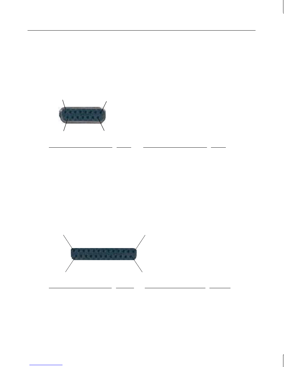
External Port Pinouts
The following figures show the external ports in their proper orientation, with the base unit
upright.
MIDI/Game
8
1
15
9
Signal
Pin
Signal
Pin
+5V
1
+5V
9
Fire button 0
2
Fire button 2
10
X-axis, joystick 1
3
X-axis, joystick 2
11
Ground
4
MIDI out
12
Ground
5
Y-axis, joystick 2
13
Y-axis, joystick 1
6
Fire button 3
14
Fire button 1
7
MIDI in
15
+5V
8
Parallel
13 1
25 14
Signal
Pin
Signal
Pin
Strobe
1
ACK - Acknowledge
10
Data 0
2
Busy
11
Data 1
3
PE - Paper Empty
12
Data 2
4
+Select
13
manuals search engine
54
Signal
Pin
Signal
Pin
Data 3
5
Auto FDXT - Auto Feed
14
Data 4
6
Error
15
Data 5
7
Init - Start
16
Data 6
8
SLCTIN - Select
17
Data 7
9
Ground
18-25
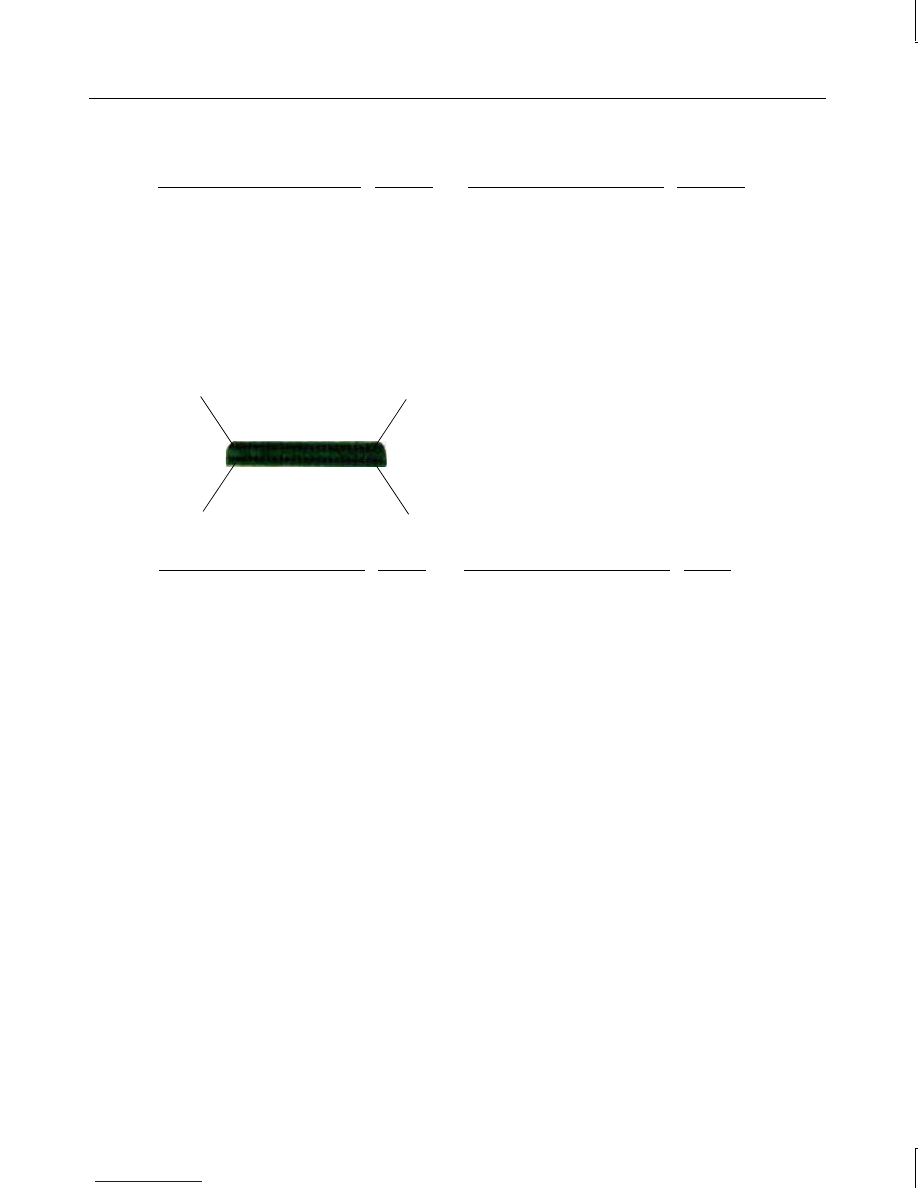
SCSI
26 50
1 25
Signal
Pin
Signal
Pin
Command Data-0
26
Attention
41
Command Data-1
27
Busy
43
Command Data-2
28
Acknowledge
44
Command Data-3
29
Reset
45
Command Data-4
30
Message
46
Command Data-5
31
Select
47
Command Data-6
32
Command
48
Command Data-7
33
Request
49
Command Data Parity
34
Input/Output
50
Terminator Power
38
NOTE
Pins 12, 13, 14, 37, and 39 are not connected; all other pins not listed are connected to
ground.
manuals search engine
55
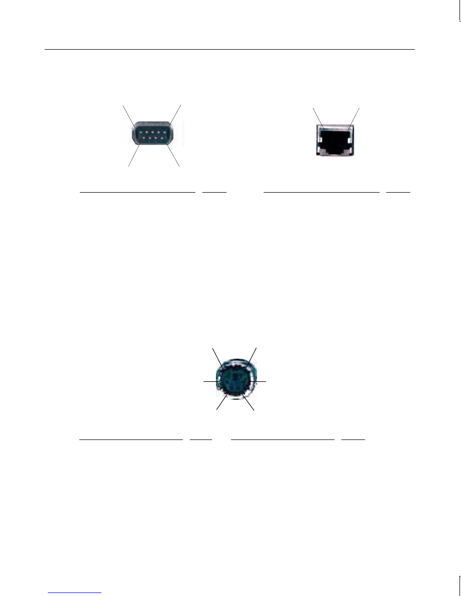
Serial (COM)
Ethernet 10/100Base-TX
1 5
6 9
1 8
Signal
Pin
Signal
Pin
DCD - Data Carrier Detect
1
TD+ - Transmit Data
1
RD - Receive Data
2
TD– - Transmit Data
2
TD - Transmit Data
3
RD+ - Receive Data
3
DTR - Data Terminal Ready
4
Reserved
4
Ground
5
Reserved
5
DSR - Data Set Ready
6
RD– - Receive Data
6
RTS - Request to Send
7
Reserved
7
CTS - Clear to Send
8
Reserved
8
RI - Ring Indicator
9
Mouse and Keyboard
6 5
4 3
2 1
Mouse Signal
Pin
Keyboard Signal
Pin
MDATA - Mouse Data
1
KDATA - Keyboard Data
1
Reserved
2
Reserved
2
Ground
3
Ground
3
Fused VCC - +5V
4
Fused VCC - +5V
4
MCLK - Mouse Clock
5
KCLK - Keyboard Clock
5
Reserved
6
Reserved
6
manuals search engine
56
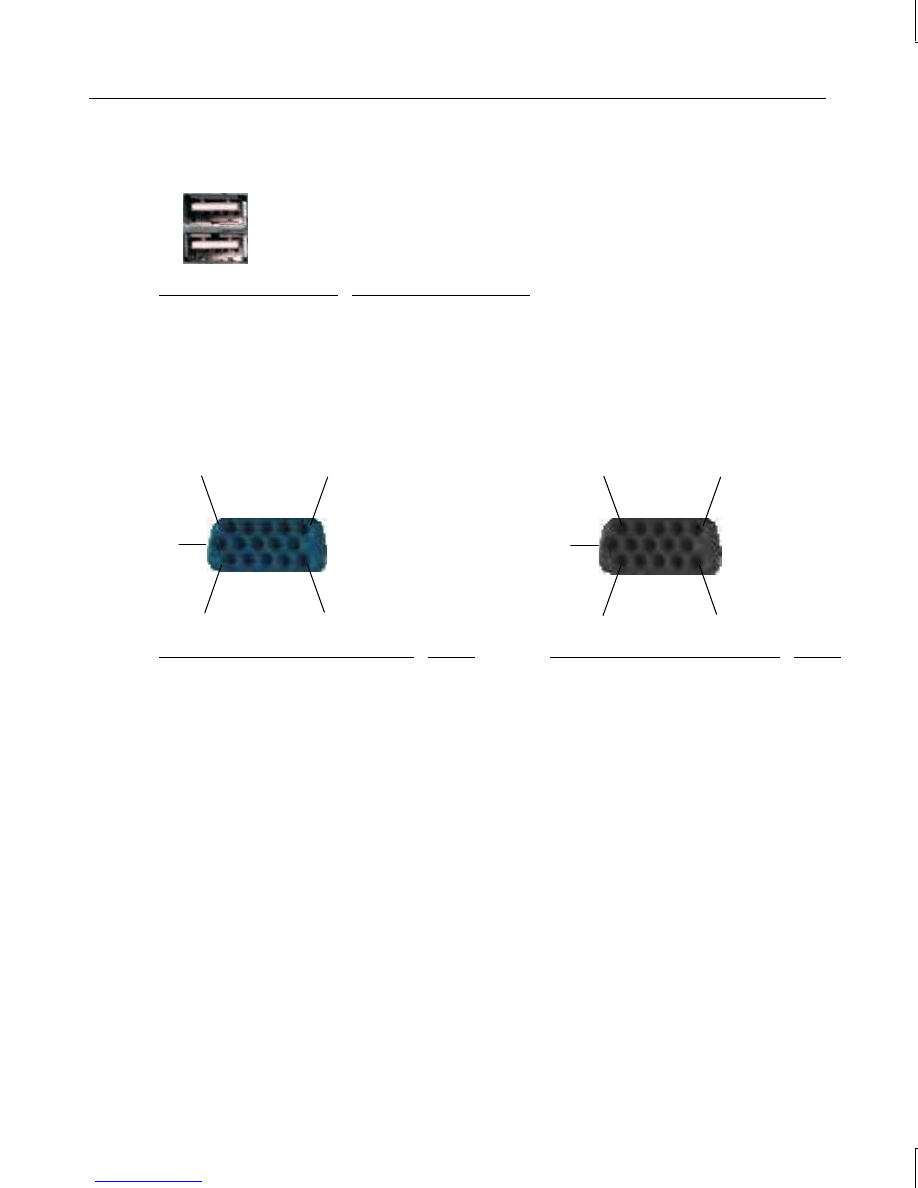
Universal Serial Bus
Signal
Contact Number
VCC (Cable Power)
1
Negative Data
2
Positive Data
3
Ground
4
Video Out
VGA In
11 15
1 5
10
11 15
1 5
10
Matrox/I3D/Z13/Z25/V25 Signal
Pin
I3D/Z13/Z25/V25 Signal
Pin
R - Red
1
R - Red
1
G - Green
2
G - Green
2
B - Blue
3
B - Blue
3
MID2 - Monitor ID2
4
MID2 - Monitor ID2
4
Ground
5
Cable Sense
5
Ground
6
Ground
6
Ground
7
Ground
7
Ground
8
Ground
8
Supply +5V (No Connect on G95)
9
No Connect
9
Ground
10
Ground
10
MID0 - Monitor ID0
11
MID0 - Monitor ID0
11
MID1 - Monitor ID1
12
MID1 - Monitor ID1
12
HSYNC - Horizontal Sync
13
HSYNC - Horizontal Sync
13
VSYNC - Vertical Sync
14
VSYNC - Vertical Sync
14
MID3 - Monitor ID3
15
MID3 - Monitor ID3
15
manuals search engine
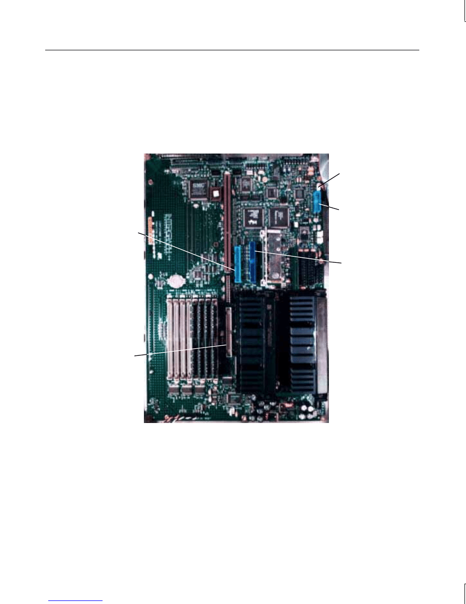
57
System Board Connector Pinouts
The following figure shows the internal connector locations. Verify Pin 1 location for each
connector on the system board.
NOTE
For the power connectors, refer to “Power Supply Information” in this chapter.
IDE
Connector
MIDI/Game
Cable
Connector
SCSI Cable
Connector
CD-ROM
Audio Cable
Connector
Floppy Disk
Drive Cable
Connector
NOTE
For the SCSI and MIDI/Game connectors shown above, refer to “External Port Pinouts”
earlier in this chapter.
manuals search engine

58
Floppy Disk
Signal
Pin
Signal
Pin
RPM
2
STEP-
20
No connect
4
WDATA-
22
DRATE0
6
WGATE-
24
INDEX-
8
TRK0-
26
MTR0-
10
WRPRT-
28
DRV1-
12
RDATA-
30
DRV0-
14
HDSEL
32
MTR1-
16
DSKCHG
34
DIR
18
Audio
Signal
Pin
Right Sound Channel
1
Ground
2
Left Sound Channel
3
Ground
4
manuals search engine
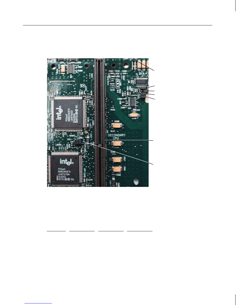
59
System Board Jumpers
The system board uses jumpers to set the CPU frequency and clock voltage.
Voltage Jumper J19
J48
Frequency
J47
Jumpers
J50
J49
Secondary CPU
S1 Slot
Voltage Jumper J39
CPU Frequency
The 200 MHz, 266 MHz, and 300 MHz CPUs use a 66 MHz P6 bus. The following table
shows the jumper settings for each frequency. IN denotes the jumper is installed on both
pins.
Jumper
200 MHz
266 MHz
300 MHz
J48
OUT
IN
IN
J47
IN
OUT
OUT
J50
IN
IN
OUT
J49
IN
IN
IN
manuals search engine

60
CPU Voltage
Pentium Pro processors use a clock voltage of 3.3 volts. Pentium II processors use a clock
voltage of 2.5 volts. The following tables show how to install the jumpers to achieve the
proper clock voltage. IN denotes the jumper is installed on both pins.
Jumper
Pentium Pro/3.3v
Pentium II/2.5v
J19
IN
OUT
J39
OUT
IN
Power Supply Information
The power supply is switchable between 90-132 VAC or 180-264 VAC, depending on the
location. The input frequency is 47-63 Hz, single phase. At full load, nominal AC line,
nominal power factor of 0.6, and temperature of 25
°
C, the power supply has a minimum
efficiency of 65 percent.
The desktop system power supply is manually ranging, and has a maximum output of 200
watts for TD-x20 and TD-x25 systems, and a maximum output of 300 watts for TDZ-x20
and TDZ-x25 systems. The deskside system power supply for all units is autoranging, and
has a maximum output of 539 watts.
DC Output Specifications
The following tables detail the power supply DC output specifications.
manuals search engine

61
Output
539 Watt Power Supply
#1
#2
#3
#4
#5
Nominal Output Voltages
1,5
+3.3
+5.1
+12.0
−
12.0
−
5.0
V
DC
Continuous Load (Maximum)
1
48
3,4
76
3,4
12
4
0.5
0.5
A
DC
Continuous Load (Minimum)
1
0
6
0
0
0
A
DC
Noise and Ripple (PARD) (DC
to 30 MHz)
2
50
50
100
250
100
mV
pp
Max
Initial Setting Tolerance
2,5
±
3%
±
3%
±
5%
±
10%
±
10%
Max
Regulation Line/Load
2,5
±
3%
±
3%
±
5%
±
10%
±
10%
Max
Overshoot (Turn on/off)
5%
5%
10%
10%
10%
Max
Notes:
1. The 539 W power supply meets or exceeds the specifications in the above table. For the
noted specifications, the Maximum values describe the smallest acceptable maximum
load, and the Minimum values describe the largest acceptable minimum load.
2. These outputs are measured at the connector of a loaded cable.
3. The +3.3 V and +5.1 V outputs do not draw more than 400 watts combined.
4. Any combination of +3.3 V, +5.1 V, and +12 V do not exceed their maximum or 539
watts of total power.
5. The sum of Initial Setting Tolerance and Line/Load Regulation does not exceed 3% for
+3.3 V output, 3% for +5.1 V output, 5% for +12.0 V output, and 10% for negative
output voltages.
manuals search engine

62
Output
300 Watt Power Supply
#1
#2
#3
#4
#5
Nominal Output Voltages
1,5
+3.3
+5.0
+12.0
−
12.0
−
5.0
V
DC
Continuous Load (Maximum)
1
20
3,4
45
3,4
5
4,5
0.5
0.5
A
DC
Continuous Load (Minimum)
1
0
2
0
0
0
A
DC
Noise and Ripple (PARD) (DC
to 30 MHz)
2
50
50
100
250
100
mV
pp
Max
Initial Setting Tolerance
6
±
3%
±
3%
±
5%
±
10%
±
10%
Max
Regulation Line/Load
2,6
±
3%
±
3%
±
5%
±
10%
±
10%
Max
Overshoot (Turn on/off)
5%
5%
10%
10%
10%
Max
Notes:
1. The 300 W power supply meets or exceeds the specifications in the above table. For the
noted specifications, the Maximum values describe the smallest acceptable maximum
load, and the Minimum values describe the largest acceptable minimum load.
2. These outputs are measured at the connector of a loaded cable.
3. The +3.3 V and +5.0 V outputs do not draw more than 240 watts combined.
4. Any combination of +3.3 V, +5.0 V, and +12 V do not exceed their maximum or 300
watts of total power.
5. The +12 V output is able to supply a peak current of 7 amps for 30 seconds.
6. The sum of Initial Setting Tolerance and Line/Load Regulation does not exceed 3% for
+3.3 V output, 3% for +5.0 V output, 5% for +12.0 V output, and 10% for negative
output voltages.
7. Current always flows from the +12 V (or -12 V) output to the fans.
8. No output exceeds 240 VA under any condition.
manuals search engine

63
Output
200 Watt Power Supply
#1
#2
#3
#4
#5
Nominal Output Voltages
1,5
+3.3
+5.0
+12.0
−
12.0
−
5.0
VDC
Continuous Load (Maximum)
1
19
3,4
34
3,4
5
4,5
0.5
0.5
ADC
Continuous Load (Minimum)
1
0
2
1
0
0
ADC
Noise and Ripple (PARD) (DC
to 30MHz)
2
50
50
100
250
100
mV
pp
Max
Initial Setting Tolerance
6
±
3%
±
5%
±
5%
±
10%
±
10%
Max
Regulation Line/Load
2,6
±
3%
±
5%
±
5%
±
10%
±
10%
Max
Overshoot (Turn on/off)
5%
5%
10%
10%
10%
Max
Notes:
1. The 200 W power supply power supply should meet or exceed these specifications. For
the noted specifications, the Maximum values describe the smallest acceptable
maximum load and the Minimum values describe the largest acceptable minimum load.
2. These outputs are measured at the connector of a loaded cable
3. The +3.3 V and +5.0 V outputs will never draw over 170 watts together.
4. Any combination of +3.3 V, +5.0 V, and +12 V cannot exceed their maximum or 200
watts of total power.
5. The +12 V output must be able to supply a peak current of 6 amps for 30 seconds.
6. The sum of Initial Setting Tolerance and Line/Load Regulation will not exceed 3% for
+3.3 V output, 5% for +5.0 V output, 5% for +12.0 V output, and 10% for negative
output voltages.
7. For +5 V output loads less than 4 amps, the +12 V maximum load shall be limited to 3.5
amps.
8. When the + 12 V output is at minimum load, the +5 V load will not exceed 50% of full
load.
9. Current will always be flowing from the +12 V output to the fans.
10. No output may exceed 240 VA under any condition.
manuals search engine

64
Cable Connectors
The following table shows the cable connectors from the power supply that connect to the
riser card and to the devices in the system.
Connector
Device
P1
System Board
P2
System Board
P3
System Board
P4
System Board
P5
System Board
P6
Hard Disk Drive
P7
CD-ROM Drive
P8
Hard Disk Drive
P9
Floppy Drive or Combo Drive
P1-P9 Connector Pinouts
Pin
Signal
Wire Color
Pin
Signal
Wire Color
P1-1
Power Good
Green
P5-1
+3.3V
Orange
P1-2
+5V
Red
P5-2
+3.3V
Orange
P1-3
+12V
Yellow
P5-3
+3.3V
Orange
P1-4
-12V (Key)
Blue
P5-4
+3.3V
Orange
P1-5
Ground
Black
P5-5
Return (Key)
Black
P1-6
Ground
Black
P5-6
Return
Black
P2-1
Return (Key)
Black
P6-1
+12V
Yellow
P2-2
Return
Black
P6-2
Return
Black
P2-3
-5V
White
P6-3
Return
Black
P2-4
+5V
Red
P6-4
+5V
Red
P2-5
+5V
Red
P2-6
+5V
Red
P7-1
+12V
Yellow
P7-2
Return
Black
P3-1
+5V
Red
P7-3
Return
Black
P3-2
+5V (Key)
Red
P7-4
+5V
Red
manuals search engine

65
Pin
Signal
Wire Color
Pin
Signal
Wire Color
P3-3
+5V
Red
P3-4
Return
Black
P8-1
+12V
Yellow
P3-5
Return
Black
P8-2
Return
Black
P3-6
Return
Black
P8-3
Return
Black
P8-4
+5V
Red
P4-1
Return
Black
P4-2
Return
Black
P9-1
+5V
Red
P4-3
Return
Black
P9-2
Return
Black
P4-4
+5V
Red
P9-3
Return
Black
P4-5
+5V
Red
P9-4
+12V
Yellow
P4-6
+5V (Key)
Red
manuals search engine


67
Index
A
antistatic wrist strap, 5
C
cable connectors, 64
cleaning
exterior surfaces, 9
keyboard, 9
mouse, 9
closing the base unit, 6
connector pinouts, 57
Crystal CS4236B, 50
D
dimensions, 45
DMA channels, 50
document conventions, v
E
electrostatic discharge
avoiding, 1
Ethernet controller, 45
expansion slots, 45
exterior surfaces
cleaning, 9
F
Fans
option board
replacing, 24
system hard disk drive
replacing, 24
G
graphics accelerator, 45
H
host bridge, 45
I
I/O addresses, 50
information
system hardware, v
installing
memory upgrade, 35
option boards, 39
ISA, 43
PCI, 42
PCI IDE, 42
Ultra SCSI devices, 36, 38
interrupt lines, 52
interrupt mapping, 51
ISA bus, 52
J
jumper connectors, 59
CPU frequency, 59
K
keyboard, 45
cleaning, 9
M
memory addresses, 51
mouse, 45
cleaning, 9
P
PCI
access panel, 4
slots
option card assignment,
47
PCI-to-ISA bridge, 45
pinouts
audio connector, 58
floppy connector, 58
MIDI/Game port, 53
manuals search engine

68
mouse and keyboard ports, 55,
56
P1-P9 connector, 64
parallel port, 53
SCSI port, 54
Serial (COM) ports, 55
Video port, 56
port pinouts, 53
power supply, 45, 60
DC output, 60
processor
Pentium II, 26
Pentium Pro, 26
processor(s), 45
R
replacing
auxiliary hard disk drives, 17
CD-ROM drive, 11
combo drive, 10
floppy disk drive, 10
option board fans, 24
optional devices, 13
power supply, 30
processor module, 26
riser card, 21
SCSI termination card, 20
system board, 28
system hard disk drive, 14
system hard disk drive fan, 24
riser card, 42, 47
S
SCSI
cable length, 39
termination, 39
Ultra, 36, 37, 38
SCSI controller, 45
SCSI-1, 39
SCSI-2, 39
SIMMs
adding, 35
height, 35
installation rules, 35
precautions, 35
type, 35
slots
primary PCI, 42
Small Computer System Interface
(SCSI)
adding internal devices, 36
sound controller, 45
features, 49
system
BIOS, 45
maintenance, 9, 19
tools required, 10, 19
memory upgrade
installing the upgrade, 35
model number, 46
upgrades, 35
system parts
replacing, 9
U
Ultra SCSI, 36, 37, 38, 39
upgrading
Pentium Pro, 26
manuals search engine
Wyszukiwarka
Podobne podstrony:
2 III stopn system referencyjnyid 19541 ppt
d6 System Reference Sheet
Hero System Shadowpunk Matrix Reference Chart
Essentials of Management Information Systems 8e References
System finansowy w Polsce 2
Systemy operacyjne
Systemy Baz Danych (cz 1 2)
Współczesne systemy polityczne X
System Warset na GPW w Warszawie
003 zmienne systemowe
elektryczna implementacja systemu binarnego
09 Architektura systemow rozproszonychid 8084 ppt
SYSTEMY EMERYTALNE
3 SYSTEMY LOGISTYCZNE
modelowanie systemow
więcej podobnych podstron