
file:///H|/Modellismo/AFV%20Interiors/[armor]%20-%20AFV%20Interiors/afvinteriors.hobbyvista.com/charb1/charb1.html
French Char B1 bis Heavy Tank, Revised 1-1-02
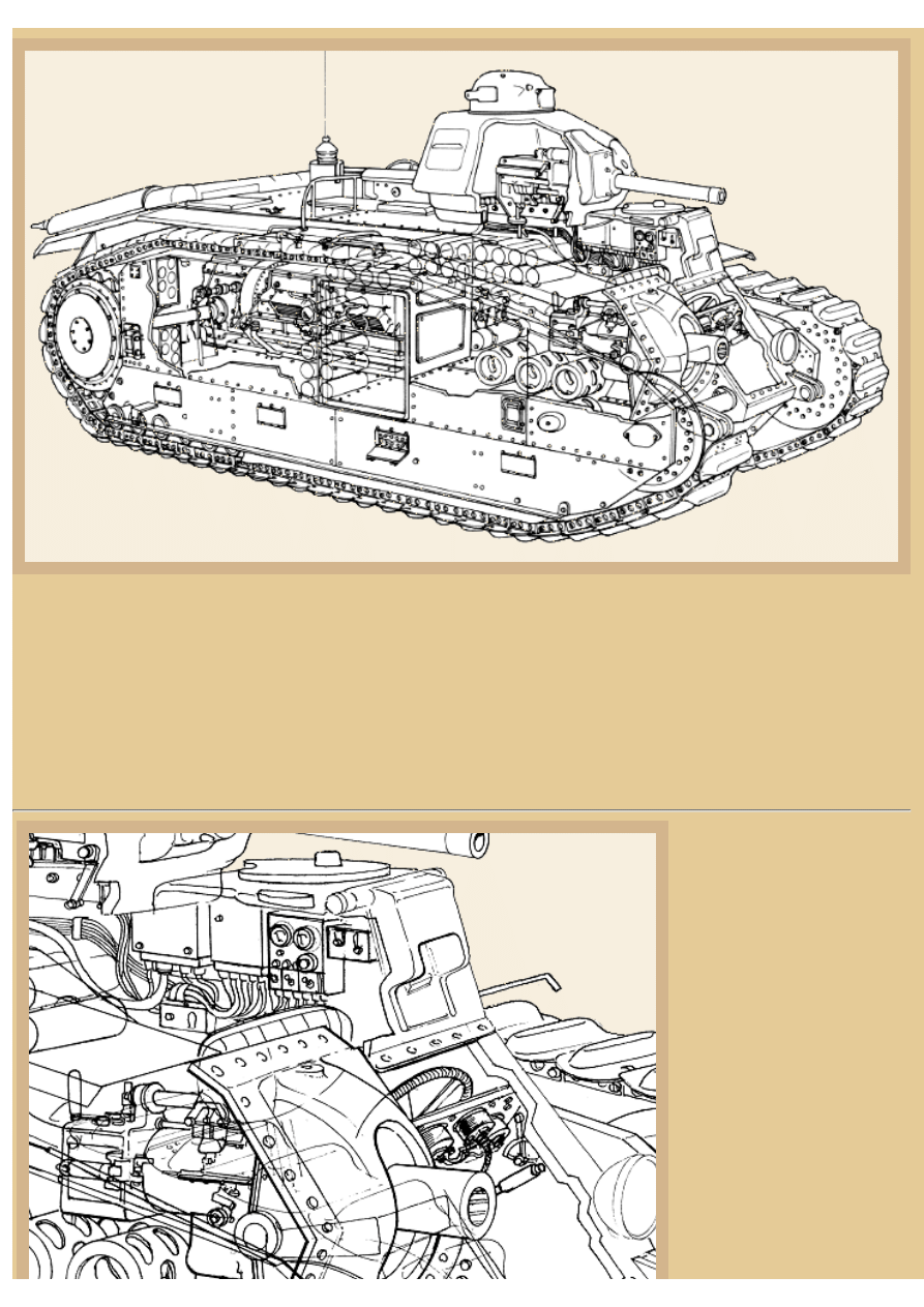
Picture 1:
The Char B1 was one of the largest French
manufactured tanks to see service in WWII,
originally beginning life as the Char B Heavy Tank
in the early 1930s. There were actually three
different Char B Heavy Tank proposals that were
built in response to General Estienne's request for a
tank weighing 14.75tons (15,000kg) and armed
with a hull-mounted 47mm or 75mm gun. One
vehicle was was submitted by FAMH (Forges et
Aciéries da la Marine et d'Homécourt), one by
FCM (Forges et Chantiers de la Méditerranée), and
one from Renault/Schneider, all three completed in
1929-1930. After trials were completed, it was
decided that the new Char B tank would use the
suspension design from FCM, the engine from
Renault, and a transmission from Schneider.
Production orders for the Char B were then placed
with FAMH, FCM, and Renault with the Rueil
Arsenal (ARL) coordinating the project.
After minor modifications, the new tank went into
series production as the Char B1, but only 35 were manufactured before the armor thickness was increased and a more
powerful engine installed. With these changes and the original turret-mounted 37mm gun exchanged for a 47mm weapon, the
Char B1 became the Char B1 bis; in French, 'bis' means (a). Over 360 of the Char B1 bis types were produced by the same
manufacturers and as they rolled off the production lines they were then handed over to the 1st, 2nd, 3rd, and 4th DCRs
(Division Cuirassées de Réserve, the principal armored divisions in early 1940) and a further 57 went to other independent tank
companies. This photo is credited from the E.C.P.A. in Paris.
file:///H|/Modellismo/AFV%20Interiors/[armor]%20-%20AFV...nteriors/afvinteriors.hobbyvista.com/charb1/charb1.html (1 di 7)06/02/2007 19.42.43
file:///H|/Modellismo/AFV%20Interiors/[armor]%20-%20AFV%20Interiors/afvinteriors.hobbyvista.com/charb1/charb1.html
Picture 2:
This schematic drawing, slightly modified from the original from the Tank Museum at Bovington, England, provides us with
some idea of the interior arrangement in the Char B1 bis. The tank had a crew of four-- driver/hull gunner, wireless operator,
loader and commander. The hull of the tank was composed of cast armor sections and armor plate bolted together (cast armor
was common in French tank design at that time). The driver was seated on the left side of the bow and the hull-mounted 75mm
SA 35 howitzer was mounted to his right. Behind the driver was the radio operator and to his right was the loader. The radio in
these vehicles was most likely the E.R. 53 Mle 1932 (E.R is Emetteur-Récepteur, or transmitter-receiver), with a 15km range.
It was operated by telegraph key, broadcast on a frequency range of 40-100m, and weighed around 80kg. The commander was
the sole occupant of the turret and the engine, transmission, and fuel tanks were all at the rear of the hull.
Picture 3:
The driver utilized a steering
wheel to direct the vehicle, the
wheel connected by a chain and
control rod system to the Naeder
hydrostatic steering system at the
rear of the tank. Interestingly, the
driver also doubled as the hull
gunner, while the wireless
operator, who had relatively little
to do, was seated further back
near the turret. The loader, who
was seated behind the 75mm
gun, was kept very busy loading
the 75mm hull weapon and
passing 47mm ammo up to the
commander/gunner in the turret.
The Naeder steering system
provided very fine and precise
directional control for gun
file:///H|/Modellismo/AFV%20Interiors/[armor]%20-%20AFV...nteriors/afvinteriors.hobbyvista.com/charb1/charb1.html (2 di 7)06/02/2007 19.42.43
file:///H|/Modellismo/AFV%20Interiors/[armor]%20-%20AFV%20Interiors/afvinteriors.hobbyvista.com/charb1/charb1.html
laying, this steering system being
a fairly advanced regenerative
controlled differential system. It
provided for a graduated turning
radius independent of the
transmission gear chosen, a
system known as hydrostatic.
The driver's 75mm gun sight was mounted just below his forward episcope. These sights were prismatic binocular sights and
they rotated behind a pair of vertical slits beneath the driver's scope. From the front of the vehicle these two slits are easily seen
below the driver's main vision port. Another interesting feature of this tank was the gyroscopic direction indicator, driven by a
compressor, and the same compressed air system also assisted in starting the engine when the normal electric starter failed.
The Renault engine was set up so the clutch was at the rear of the power plant and it then directly transferred power to a five-
speed gearbox and then through a differential to both the rear sprockets. The Naeder hydrostatic steering pump sat on top of the
gearbox and obtained its power from a chain drive takeoff from the main drive shaft, just before the gearbox. This type of
steering system is also commonly called a double differential steering system, the design originally manufactured at the
Schneider Company under the direction of E. Braillié in the early 1920s. The hydrostatic steering drive ('hydrostatic' is just
another word for 'hydraulic') gave an infinity of turning radii for each gear of the gearbox, with the radii varying continuously,
from the smallest possible radius in one direction to the smallest radius in the other. In its mid-position it held the steering input
shaft stationary, preventing differential action between the tracks when running straight ahead.
The steering was controlled by two clutches that transferred the power to the second differential (again, mounted on top of the
main unit) and then to a set of cross-shafts running parallel to the main shafts. This second set of cross-shafts controlled the
speed of the primary drive shafts because they rotated in the oppositely direction. In this way the Naeder system could slow
either drive shaft that it was associated with and thereby slow the attached sprocket, the action depending on which of the
steering clutches was engaged by the driver as he used the levers up at the front of the tank. Although it was complicated, the
Naeder steering system allowed the small and precise corrections in steering that were necessary to accurately turn the vehicle
just inches in one direction, allowing surprisingly accurate aiming of the hull-mounted 75mm gun.
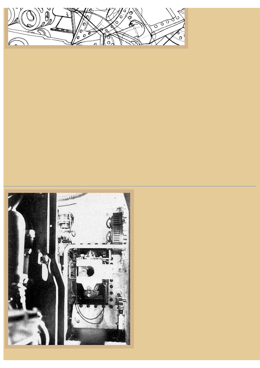
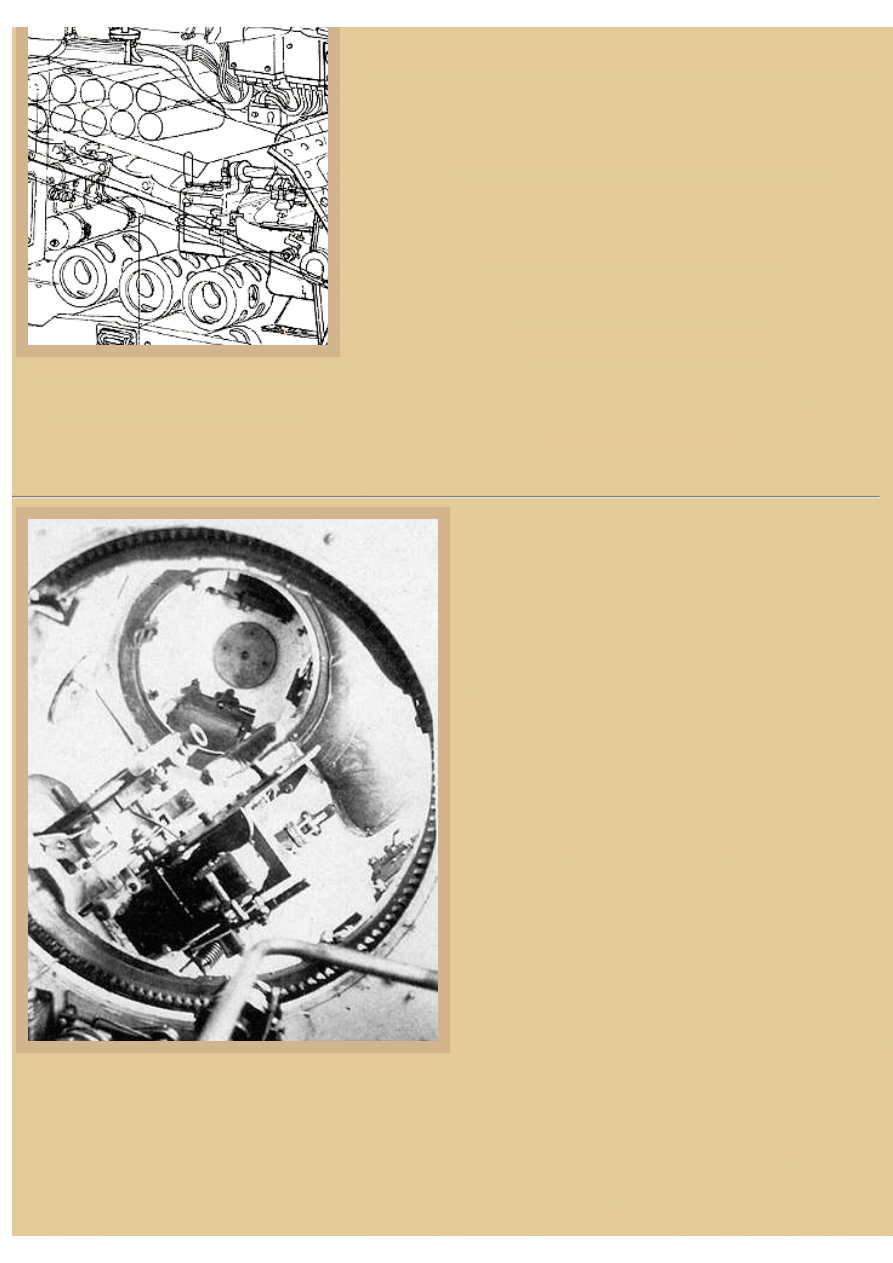
Picture 4:
This is the view looking forward in the hull through the open
engine compartment hatch in the firewall to the breech of the
75mm howitzer mounted in the front glacis. The forward
hull gun is the 75mm SA 35 with short barrel (only 17.1cal)
which was installed in a mount that provided an elevation of
+25 to -15 degrees. The howitzer was fixed in traverse,
being aimed solely by the driver, in elevation by a hand
wheel, and in traverse by turning the entire tank. Another
unusual feature of the Char B1 bis was the use of the
previously mentioned air compressor to blow fumes out the
howitzer barrel after firing the gun and before opening the
breech (an early fume extractor). The breech was of the
horizontal sliding block type (shown open in this photo) and
74 rounds of 75mm HE ammo was generally carried in
storage bins/racks along the vehicle sides.
Visible just below and to the right of the gun breech is the
rear of the fixed 7.5mm Châtellerault Mle 1931 machine
gun. This weapon was fired by the driver via a cable
connection, which is not installed in this photograph. The
same cable could be led up to the turret where the
commander could also fire this MG. There were over 5,000
rounds of MG ammo stored in 32 drums (or boxes) for both
this weapon and the coaxial MG up in the turret; two typical
150-round ammo drums used with the Châtellerault MG are
seen here stowed above the 75mm gun mount. To our left is
the Renault engine with its oil cleaner. The Char B1 bis was
file:///H|/Modellismo/AFV%20Interiors/[armor]%20-%20AFV...nteriors/afvinteriors.hobbyvista.com/charb1/charb1.html (3 di 7)06/02/2007 19.42.43
file:///H|/Modellismo/AFV%20Interiors/[armor]%20-%20AFV%20Interiors/afvinteriors.hobbyvista.com/charb1/charb1.html
powered by a Renault 6-cylinder, 307hp, gasoline engine providing around 17mph (28kph) with a range of 93 miles from a full
tank of gas. This was an adaptation of an existing Renault aircraft engine with magneto ignition.
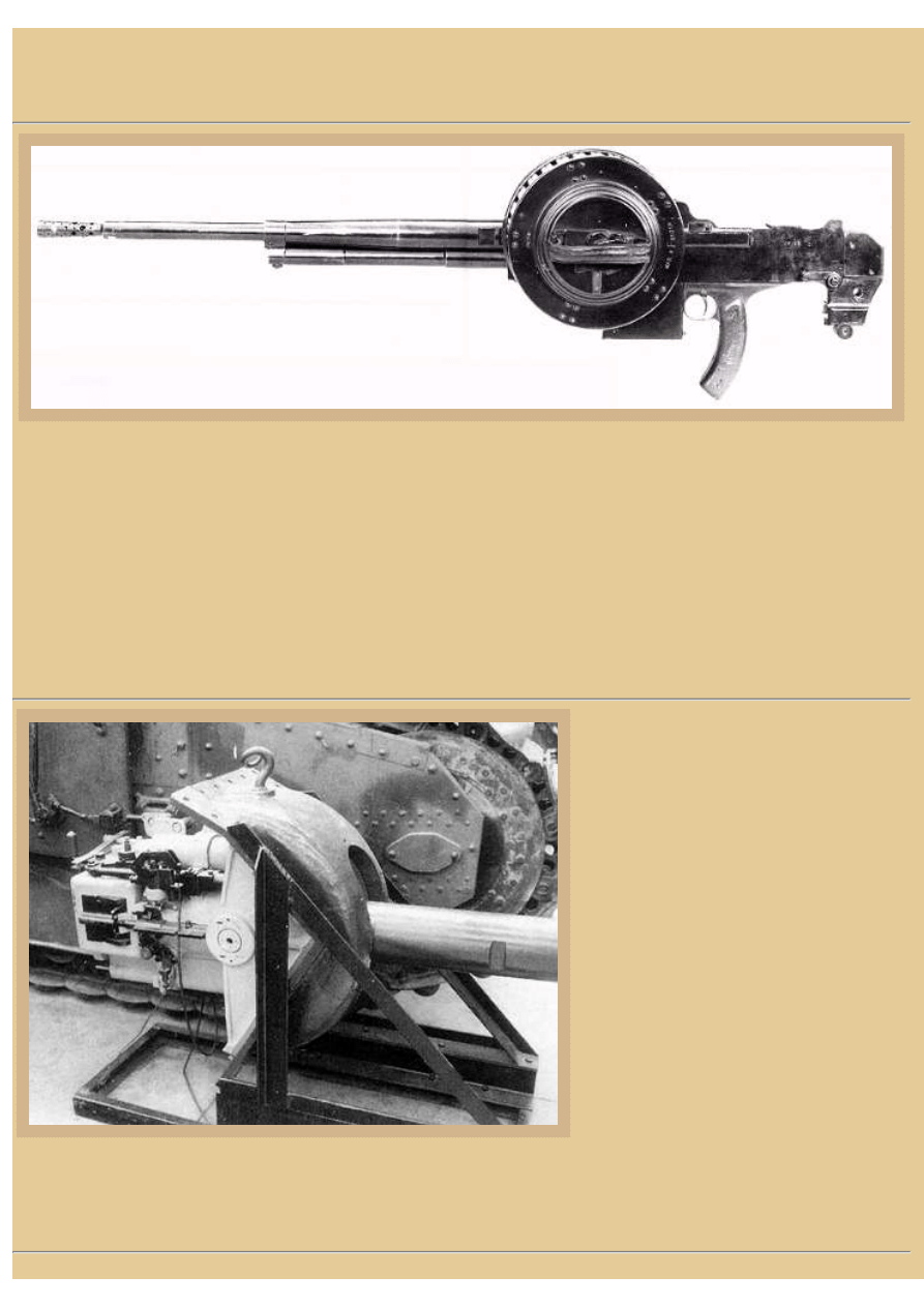
Picture 5:
The 7.5mm Châtellerault Mle (Model) 1931 machine gun was one of a number of MGs produced by the Manufacture d'Armes
de Châtellerault, located in the French town of the same name. Their first success was actually in the development and
production of a rimless cartridge better suited to automatic weapons than the typical 8mm rimmed Lebel rifle cartridge then in
French service after WWI. The first MG developed around this cartridge was the Mle 1924, but it was redesigned after
prototype failures upon demonstration and after its successful debut the gun became the Mle 24/29 and was quickly accepted
into French Army service. In 1931, a modified version of the MG was developed and issued for use in the Maginot Line
fortifications and this version used a side-mounted drum magazine containing 150 rounds as you see here. The same weapon
was also used in a number of French manufactured tanks in the late 1930's, including our Char B1 bis. The Mle 24/29 and the
31 were all used by the Germans after the fall of France in WWII, and indeed continued to be used by French Colonial Forces
for many years after the war, being still found occasionally today in armies of former French colonies.
Picture 6:
This is a picture of the 75mm gun and mount
next to a preserved museum Char B1 bis. The
photo provides a better indication of the depth
of the breech and a few details of the cradle
and mechanism, including the trunions. The
breech block is closed here and painted black,
and the recuperator and recoil tubes at the top
and bottom of the howitzer are also visible.
Recall that the MG mounted near the 75mm
gun was not installed in the gun mount, but
was fixed to the hull to the right of the mount,
and therefore it is not seen in this picture.
The howitzer fired the HE shell Mle 1915 and
the AP shell Mle 1910, weighing 5.550kg and
6.400kg respectively. Muzzle velocity was
around 490m/s and 470m/s, the HE shell filled
with 740g of explosive. The AP shell is said to
have been able to penetrate around 40mm of
armor at 30 degrees obliquity at 400 meters,
but the type of armor and other penetration data details are not available. The AP shell Mle 1910 was uncapped (non coiffé).
The weapon had the same general design layout as the Mle 31 fortress gun, with the semi-automatic breech of the Mle 33
fortress gun. Recoil length was 320mm and the rate of fire was as high as 15 rounds/minute.
file:///H|/Modellismo/AFV%20Interiors/[armor]%20-%20AFV...nteriors/afvinteriors.hobbyvista.com/charb1/charb1.html (4 di 7)06/02/2007 19.42.43
file:///H|/Modellismo/AFV%20Interiors/[armor]%20-%20AFV%20Interiors/afvinteriors.hobbyvista.com/charb1/charb1.html
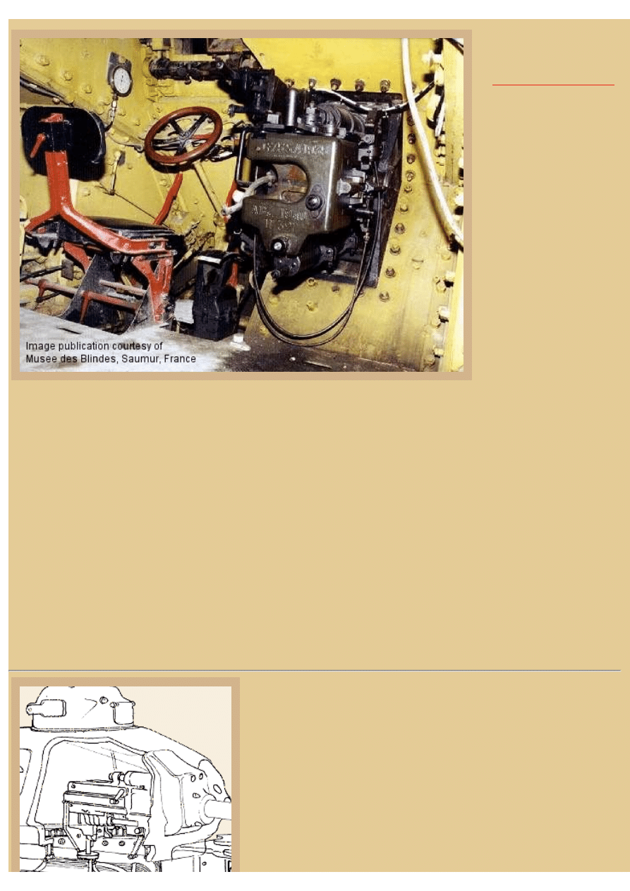
Picture 7:
Here is the view looking into
a Char B1 bis preserved at
the
showing the driver's position
to our left and what is left of
the 75mm gun breech to our
right. The photo was taken by
Mikel Ezcurra and loaned to
AFV INTERIORS, and as
you can see, much of the
internal equipment is missing
from this tank, including the
recoil guard around the back
of the gun. However, the
driver's unique seat, viewing
flap, and gun sight are still
mostly intact, and the large
75mm gun breech is also
clear. An elevation hand
wheel on the upper left corner
of the gun mount allowed the
gunner to lay the weapon
correctly for elevation. Recall
that this gun is a low velocity
howitzer, and as such it was intended primarily for use as infantry support against non-armored targets and for indirect firing
missions.
You can see that the instrument panel in front of the steering wheel is devoid of all gages, and the one large gage on the wall to
the driver's left (a tachometer?) is a modern addition. Notice also the emergency, or back-up hand brake levers (here painted
red), one located on each side of the seat. The brake drums were mounted externally at each end of the auxiliary differential at
the rear of the tank and they were operated with servo-assistance by these driver's hand brakes as well as a foot pedal. These
levers and brakes could also be used for steering in an emergency. The Fieux centrifugal transmission had five forward and one
reverse gear, and the driver changed gears by means of a shift lever mounted on the floor to his right. Down at his feet are the
accelerator, brake, and clutch pedals, used in the typical way. Only the driver and the commander up in the turret were able to
see out of the tank, one of the main drawbacks of this heavily armored vehicle. The floor is not original in this specimen and
the paint has also been changed. French tanks were painted predominately white inside with most of the metal equipment black
or some other primer color. The pale green hull walls and the red seat support are paint creations made by the museum staff.
What is also clear here is the extensive use of bolts holding the rolled and cast armor pieces to the angle iron framing. The gun
cradle is also bolted in place, the bolts seen surrounding the heavy mounting. One of the cables you see looping under the
breech is the firing cable, leading from the elevation hand wheel near the driver to the firing mechanism attached to the right
side of the breech block. The breech actuating handle is on the top of the breech ring.
Picture 8:
The APX turret was the same type as mounted on the SOUMA S-35, and
because it was designed as a one-man turret, the commander was tasked with
loading, aiming, and firing the turret weapons, as well as commanding the
movement of the tank and actions of the tank crew. As with most one-man
turrets, this was asking too much of the commander, and the resulting tactical
use of the Char B1 bis suffered accordingly.
As you can see from the photos and drawings, there were three primary entry/
exit hatches for the crew-- one on the right hull wall, one above the driver, and
one on the right rear of the turret. But there were also two emergency escape
hatches provided-- one on the belly of the tank and one in the roof of the
file:///H|/Modellismo/AFV%20Interiors/[armor]%20-%20AFV...nteriors/afvinteriors.hobbyvista.com/charb1/charb1.html (5 di 7)06/02/2007 19.42.43
file:///H|/Modellismo/AFV%20Interiors/[armor]%20-%20AFV%20Interiors/afvinteriors.hobbyvista.com/charb1/charb1.html
engine compartment. The engine, transmission and fuel tanks were all in the
rear of the hull, and the engine was open to a passage way on the right side
that led clear back to the rear armor plate. In the sponson to the left of the
engine were the large radiator and fans, as well as a 100 liter gas tank. In the
right sponson were two additional fuel tanks, one of 200 liters and one of 100.
All these fuel tanks were self-sealing, but the 400 liters of fuel was dismally
too little, leaving many tanks later stranded in combat due to lack of gasoline.
Access to the passage on the left side of the engine was through a hatch in the
firewall.
Many of the 47mm rounds for the turret gun were stowed in racks in the back
of this passageway; as far as I can tell there were no rounds stored up in the
turret. The 75mm howitzer rounds were stored in tubes along both sides of the
sponsons in the forward hull, while the larger tubes (with the holes) you see
drawn along the bottom of the hull were for MG ammo drums.
In May of 1940, each DCR had an establishment of four battalions of combat
tanks, organized in a demi-brigade of two battalions of Char B1 heavy tanks and a demi-brigade of two battalions of much
lighter tanks, in most cases H39 tanks. One of the only ways to identify the difference between the Char B1 and the Char B1
bis is the longer gun tube of the 47mm SA 35 compared to the much shorter SA 34. Maximum armor thickness was also
increased from 40mm to 60mm on the bis, but this is difficult to determine from photographs.
Picture 9:
Here is the view looking up into an AMX turret from below,
illustrating the bottom of the 47mm gun and coaxial 7.5mm
Reibel MG. The sights for the gunner are on the far left of all
that hardware, near the coax MG, and the telescopic sight is
provided with a padded eye cup to protect the gunner. Just
below the sight is the butt of the coaxial Reibel MG,
originally developed for the French infantry, with a range of
around 2400m and a rate of fire of approximately 500 rounds/
minute. The breech of the 47mm SA Mle 35 gun is to the
right of the coax MG.
Barely visible in the photo is the shoulder pad that could be
used to manually elevate the main weapon; it is attached to
the recoil guard on the left side of the 47mm breech. The
ability to disconnect the weapon cradle from the hand
elevation wheel mechanism and elevate it manually by
shoulder was common to both British and American AFV
designs of the same time. It was believed that the gunner had
a better chance of hitting a target while on the move using the
shoulder lay than with a hand wheel. Fifty rounds of 47mm
AP and HE could be carried in the tank, all stowed in the hull
as I mentioned previously (some perhaps under the floor?),
the ammo having to be handed up to the commander by the
loader below. By the way, the coaxial turret Reibel MG could
be independently traversed in its own ball mount an additional
10 degrees to either side of center when required.
There was no turret basket in the Char B1 bis heavy tank so the commander walked on the hull floor as the turret traversed
(electrically or manually- the mechanism is partially obscured by a bar at the bottom of the photo). The turret had viewing
blocks on both side walls, with a handle/lever beside each to open or close the protective armored cover (just visible at the
lower right of the turret in the picture). There was also a large head pad on the ceiling of the turret over the gun sight, just
visible here to the right of the cupola. The observation cupola is visible at the top of the picture and viewing blocks on both
sides are evident, with another head pad at the center of the dome. There was also a large vision flap at the front of the cupola
that could be opened and was protected with a glass block. There was no hatch in the cupola until the Germans added one in
file:///H|/Modellismo/AFV%20Interiors/[armor]%20-%20AFV...nteriors/afvinteriors.hobbyvista.com/charb1/charb1.html (6 di 7)06/02/2007 19.42.43
file:///H|/Modellismo/AFV%20Interiors/[armor]%20-%20AFV%20Interiors/afvinteriors.hobbyvista.com/charb1/charb1.html
some of the vehicles they captured and later used.
A few Char B1 bis tanks captured by the Germans in running order (nicknamed Kolosse by the Germans) were converted to
flamethrower tanks and then officially named by them Pz.Kpfw. B-2 740(f). The flame gun replaced the 75mm main howitzer
but the turret weapon was generally retained for its anti-tank capability.
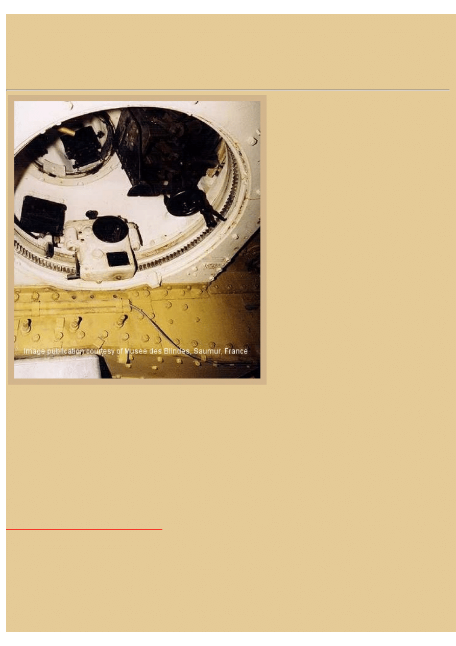
Picture 10:
Our last image shows the interior of the same
museum preserved Char B1 bis we saw earlier,
again missing much of its equipment. Below is the
left hull wall with part of the large engine air intake
duct and radiator cover visible at the bottom. The
radiator louvers on the left hull side were
particularly attractive targets for anti-tank gunners
and proved to be the weakest link in the Char B1
bis armor. Up in the turret are the dark breeches
and mounting cradles for the turret weapons, the
turret currently pointing directly forward. One of
the side vision flaps is also visible here, appearing
black because it is opened. Up above is the
commander's cupola; notice that the cupola is
offset to the left of the turret roof. I believe the box
you see on the turret ring (with the black manual
hand wheel) is the traverse control, while the
manual elevation hand wheel is seen off to the far
right, attached to the gun cradle. The cradle is
connected to the turret ceiling via a worm geared
rod, and the handle you see here operates the worm
gear, making the attached gun cradle climb or
descend the rod, thereby depressing or elevating
the gun.
This 47mm SA 35 gun fired the French HE shell
Mle 1932, weighing 1.415 kg, at approximately
590 m/s. The AP round was the Mle 1935,
weighing 1.500 kg, and traveling at around 700 m/s after leaving the gun tube. This was a "capped" round (coiffé sans f. ogive)
and is said to have been capable of penetrating 40mm of armor at 400 meters at 30 degree obliquity. Rate of fire was the same
as the 75mm gun, around 15 rounds/minute.
By the way, the Renault 307 in-line engine used in the Char B1 bis was a direct cousin to the six-cylinder Renault-Deutsch
engine that powered the French Caudron to a runaway win in the 1936 Thompson Trophy Race.
My thanks to Mikel Ezcurra for loaning us a couple of his Char B1 bis photographs taken at the Saumur Museum. Other photos
and drawings are from the Tank Museum, in Bovington, England. If you have additional information or illustrations concerning
the interior of this interesting AFV and would be interested in sharing it with our readers, we would be delighted to hear from
you.
BACK TO AFV INTERIORS HOME PAGE
(c) 2001, 2003 AFV INTERIORS Web Magazine
file:///H|/Modellismo/AFV%20Interiors/[armor]%20-%20AFV...nteriors/afvinteriors.hobbyvista.com/charb1/charb1.html (7 di 7)06/02/2007 19.42.43
Document Outline
Wyszukiwarka
Podobne podstrony:
OD33 Panzer IV vs Char B1 Bis France 1940
AFV Interiors Water Buffalo
Afv Interiors Isu 152
AFV Interiors CV 33 35
AFV Interiors German AFV Radio Equipment In WWII
AFV Interiors M1A2 Abrams
AFV Interiors British Medium Tank Mk I & Mk II
AFV Interiors Czech Light Tank, LT vz 38, Pz Kpfw 38(t)
AFV Interiors Leopard 2
Afv Interiors Daimler Scout Car
AFV Interiors Otter
Afv Interiors Mk V
AFV Interiors Marder III
AFV Interiors M113 Toa
AFV Interiors Fahrpanzer
AFV Interiors Semovente Da 75 18
AFV Interiors LVT
AFV Interiors IS 2
AFV Interiors Flakpanzer 38t
więcej podobnych podstron