file:///H|/Modellismo/AFV%20Interiors/[armor]%20-%20AFV%20Interiors/afvinteriors.hobbyvista.com/isu152/isu152a.html
Soviet Self Propelled Gun ISU-152, Part 1
The ISU-152 was a further development of the SU-152 Assault Howitzer, but based on the IS tank's (Iosef Stalin)
lower chassis and running gear instead of the KV tank's (KV from the pre war defense minister, Klimenti
Voroshilov). Although the ISU-152 mounted the same 152mm M1937/43 (ML-20S) gun-howitzer of the SU-152,
the new crew compartment was now higher (as the IS chassis was not as deep as the KV) and more rectangular.
The old circular KV hatches were replaced with the SU-100 style cupolas and new standard periscopes installed in
each. The new ISU 152, and the similar ISU-122 (fitted with a 122mm A-19 cannon), were first produced at
Chelyabinsk during late 1943 at the same time as the IS-1 heavy tanks.
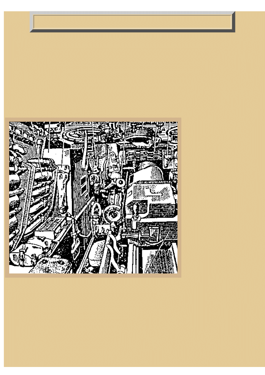
Picture 1:
If we drop down through the
gunner's circular hatch on the left
side of the roof, we would be
greeted with this view of the
interior, taken from the operator's
manual. The crew of the ISU-152
included 5 men- driver at the left
front of the bow, gunner seated
directly to the left of the gun,
commander to the right, and two
loaders found at the rear corners
of the vehicle. Once your eyes
adjust to the very busy style of
this operator's manual drawing
you will recognize the breech of
the big gun-howitzer to the right
and ammo projectiles stored in
racks to our left.
The AFV carries only 20 rounds
of two-part ammo (semi-fixed),
requiring 40 rack positions for the
separate projectiles and charges.
Most of the ammo is stacked
along both sides of the hull, projectiles on this side and charges on the other. The manual breech handle for the gun-
howitzer is to the upper left of the block and just to its left are the two manual gun laying hand wheels for the
gunner. Limited traverse is controlled by the hand wheel closest to the breech and elevation by the second wheel,
angled slightly, to the left of the traverse wheel. Over-head is the gunner's circular two piece escape hatch with his
periscope protruding through the front half visible here. Each rack to the gunner's left holds 10 AP or HE
projectiles, loaded on each shelf two deep, with the tip facing to the rear, while the shell charges are racked on the
right of the hull and under the gun (not seen here). Also on this left side can be seen a large fuel tank up on the
sponson and a small shovel is mounted on the sponson wall to the left of the gunner's brown padded seat bottom.
Further back on the sponson towards us are MG ammo boxes and rucksacks for gas masks while above the 152mm
projectile racks is a shelf for hand grenades. A large circular exhaust fan is mounted in the roof directly over the
gun with a simple screen to shield the fan blades at the bottom.
file:///H|/Modellismo/AFV%20Interiors/[armor]%20-%20AFV...teriors/afvinteriors.hobbyvista.com/isu152/isu152a.html (1 di 6)06/02/2007 20.08.56
file:///H|/Modellismo/AFV%20Interiors/[armor]%20-%20AFV%20Interiors/afvinteriors.hobbyvista.com/isu152/isu152a.html
Picture 2:
This is a close-up crop of a photo loaned to
AFV INTERIORS by Steve Zaloga
illustrating some of the gunner's controls for
the massive 152mm gun-howitzer. Both the
traverse hand wheel and elevation wheel (to
its left) are visible here as well as the mount
for the indirect gunner's sight, which is also
more or less intact here. The gun mount's
elevation gear and the hand wheel's rotating
pinion gear are to the right of the sight mount.
A head bump pad is attached at eye level on
the side of the howitzer and directly below is
the pull lanyard to fire the gun. Even with its
huge exterior dimensions, space is still
cramped inside the ISU-152, primarily due to
the immense size of the gun and the fact the
area over the sponsons is taken with stored
ammo and other gear. Just visible in this
photo are the pistol port plugs on either side
of the gun mantlet, fairly high up the front
armor plate.
Operating a self-propelled limited-traverse
gun system takes a lot of coordination
between the crew members, particularly the driver and commander. The vehicle must always be turned toward the
target to fire the gun, regardless of the proposed direction of travel or surrounding terrain conditions. Only then can
the gunner acquire the target through his telescopic sight and the limited traverse of the gun, in this case just 5
degrees left or right of center. Barely visible down to the lower left is the driver's seat and his small forward
instrument panel. Armor thickness on the ISU-152 ranged from 20mm (0.79in) on the hull roof to 110mm (4.33in)
on the front plates and gun mantlet.
Picture 3:
This image shows
the gunner's
position again as
he rides next to the
152mm weapon.
His seat is attached
to the gun mount
by a single steel
tube and traverses/
elevates with the gun. The gun laying hand wheels are directly to his right and in front of him. The gunner's ST-10
2x telescopic sight is drawn as a slanting tube leading forward to the gun mantlet while the indirect sight unit is
drawn as the dark circular shape below, with the long adjustment and alignment handles leading up across the
telescope tube. The telescopic sight has a large padded eye ring and a head bump pad directly above the eyepiece.
file:///H|/Modellismo/AFV%20Interiors/[armor]%20-%20AFV...teriors/afvinteriors.hobbyvista.com/isu152/isu152a.html (2 di 6)06/02/2007 20.08.56
file:///H|/Modellismo/AFV%20Interiors/[armor]%20-%20AFV%20Interiors/afvinteriors.hobbyvista.com/isu152/isu152a.html
The gun-howitzer slides on a long recoil run-out tray and one of the recoil shields on this side is seen to the rear,
above a small storage box for spare gun parts. Elevation for the weapon in this vehicle is +20 to -3 degrees and
total traverse is 10 degrees from side to side.
Standing outside the AFV the 152mm armed vehicle can be differentiated from the 122mm models by the larger
diameter gun-howitzer tube, large multi-vented muzzle break and shorter tube length. This image was loaned to
AFV INTERIORS by Valera Potapov of the web page
. A color rendition of the drawing
can be found in his web page as well as additional information about the ISU-152 and other Soviet/Russian AFVs.
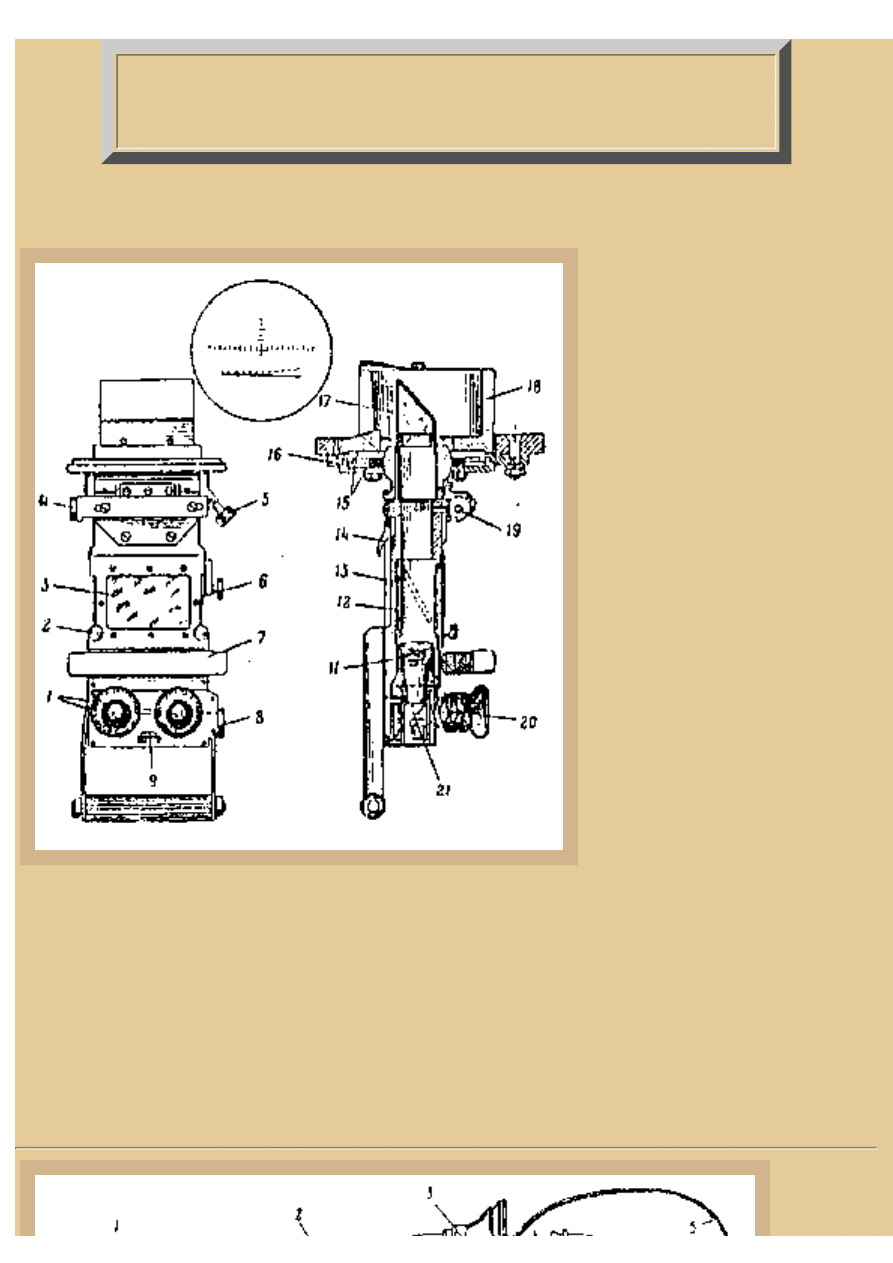
Picture 4:
The indirect dial sight (non-optical) used was typical of most
European artillery sight designs. It includes adjustments for azimuth
and elevation with spirit bubble levels (3) to indicate level gun
positions. The drum to the left (15) is calibrated for each ammo type
and allows proper elevation deviations for the aerodynamics of each
projectile. The long levers rising to the right (6,7) are speed
adjusting bars. Indirect firing requires a predetermined aiming point
to be established before hand and sighted precisely. Then, when an
enemy location is indicated on a map for a fire mission, the angle of
deviation to the target on the map is determined from the
established aiming point. The sight adjustments are set to that angle
and the gun traversed until the aiming point is again in the sight.
Once the elevation is worked out via a table for the distance
required and elevation of both the target and gun-howitzer, the sight
is adjusted again and the gun is elevated, now ready for firing. With
a forward observer calling in minor adjustments, the gun-howitzer
can hit its target after 2 or 3 ranging shots. For a 152mm gun-
howitzer the area of complete destruction (except armored targets)
around each HE shell blast is roughly 20 meters in diameter.
Picture 5:
The gunner's periscope, mounted up in his over-head
hatch, was not a sight but a typical Mk.4 periscope, seen
here in both its original version (with ball handles at
either side), and the improved model's one-piece handle
type below. This was the general issue British tank
periscope used during WWII and was supplied to the
Soviets in numbers within Lend Lease until they could
manufacture their own copies. The periscope is
mounted in the forward half of the over-head hatch and
is protected by an armored ring with a sheet metal top
cover. The mounting allows the periscope to be both
fully rotated and tilted up and down with the handles to
control these movements. A slide is provided for back
laying so the periscope may be used from either side
without having to rotate it, the slide having a forehead
bump pad attached to it. You can see that the upper and
file:///H|/Modellismo/AFV%20Interiors/[armor]%20-%20AFV...teriors/afvinteriors.hobbyvista.com/isu152/isu152a.html (3 di 6)06/02/2007 20.08.56
file:///H|/Modellismo/AFV%20Interiors/[armor]%20-%20AFV%20Interiors/afvinteriors.hobbyvista.com/isu152/isu152a.html
lower lenses were separate units and they could be
replaced independently. This was done by releasing the
latch seen on the front of the box mount (upper right drawing) and "breaking" the body to pivot the hinged lower
section forward. The small knob at the upper right of the mount (seen in the upper left drawing) is the locking
screw to keep the periscope from tilting. A similar knob is used to lock the periscope from rotating, but is not
visible here.
Picture 6:
The illustration from the operator's manual shows similar items of interest. The telescope and indirect sight are
drawn in their normal positions and the head pad on the side of the gun can be seen with the firing lanyard hanging
below. The large twin recoil damper/recuperators for the gun-howitzer are mounted below the barrel and the front
end caps of these cylinders are up in the gun mantlet. Access to the cylinders is via a large rectangular cover plate
just under the tube on the outside of the mantlet.
Picture 7:
The interrupted screw breech looked like this and was
operated by the large vertical handle. First action of the
handle rotated the breech a quarter turn, disengaging the
screw and allowing the block to be pulled from the
breech. After the spent shell was ejected a new round
was loaded and the breech closed. Due to the meager 20
rounds of ammo carried inside the vehicle, many period
photos show ISU-152s traveling with wooden ammo
crates stacked on the back decks. The weapon fires an
HE shell weighing 96lbs to a range of nearly 9km. Even
with its slow rate of fire (due primarily to the two-part
ammo) the weapon can fire three or four 107lb AP
projectiles each minute to over 4,000 meters.
file:///H|/Modellismo/AFV%20Interiors/[armor]%20-%20AFV...teriors/afvinteriors.hobbyvista.com/isu152/isu152a.html (4 di 6)06/02/2007 20.08.56
file:///H|/Modellismo/AFV%20Interiors/[armor]%20-%20AFV%20Interiors/afvinteriors.hobbyvista.com/isu152/isu152a.html
Picture 8:
Sheet metal ammo bins for
projectiles were built in this
configuration for the left side
of the fighting compartment.
Painted the typical white
interior color they were
simply and lightly made with
wooden blocks for the
projectile end tip supports.
Only the top shelf used the
metal hoop quick release
straps, the others have release
tabs on the cross bars to allow
removing the ammo. The
hoop straps on the right are used to stow charges under the gun. The entire rear half of the superstructure roof was
bolted in place and could be removed for major vehicle repairs. At the left rear of the roof there is a large
rectangular hatch with another rotating Mk.4 periscope for the loader's use. The hatch is extended down the back
plate of the superstructure so that the top hatch could swing forward and the back portion swing down, providing a
very large access space for loading ammo into the racks on both sponsons.
Picture 9:
The right side of the fighting compartment
is drawn here, with the gun to the left and
commander's position to the right. Since
the gun is mounted off center toward the
right of the vehicle there is even less space
on this side of the howitzer. Up above is
the commander's two-part circular hatch
shown here with his binocular ranging
periscope installed. The basic vehicle radio
equipment is mounted on a shelf on the
front wall and also on the right. Two dark
charge casings are mounted horizontally
on the right hull wall and above them are
boxes for spare MG parts and a first aid
kit. From 1945 on there was a 12.7mm
M1938 DShk anti aircraft machine gun
mounted up on the commander's cupola
and the crew were from the start armed
with either PPS or PPSh sub-machine guns
as well as person side arms. A few more of
the 20 shell charges are seen in their rack
to the far right of the sketch and seat pads
are located on the sponson for the
commander and right side loader.
As far as I can tell the commander and loader's seats did not have backs, which must have made life interesting for
the commander. He could stand in his hatch at his position to observe the area around his vehicle or close down the
hatch and either sit sideways or stand next to the gun to use his periscope, radio, etc. The rear left loader's seat was
file:///H|/Modellismo/AFV%20Interiors/[armor]%20-%20AFV...teriors/afvinteriors.hobbyvista.com/isu152/isu152a.html (5 di 6)06/02/2007 20.08.56
file:///H|/Modellismo/AFV%20Interiors/[armor]%20-%20AFV%20Interiors/afvinteriors.hobbyvista.com/isu152/isu152a.html
a fold down affair mounted on the sponson and used only when traveling. You can see a bit of it at the lower left
corner of Picture 1 above. This is the end of Part 1 of our exploration of the interior of the big Soviet SPH.
Picture 10:
Just how big is the 152mm Howitzer? If you
remove it from the ISU-152 and place it on
a mount with wheels it looks like this. The
field gun and mount originated from a
design of the early 1930s and was one of the
Soviet's primary heavy artillery weapons of
WWII. Artillery in the Soviet arsenal
benefited greatly from the Second Five Year
Plan, and when the ML-20 was adopted in
1937 it was only one of 15 new field pieces
to appear between 1935 and 1941. This
propaganda photograph illustrates nicely the
characteristic long multi-slotted muzzle break and the dual spring supports for the weapon. The two loaders are
holding both a charge case and an HE projectile, with the projectile being layed into the breech and the charge
ready to follow. The field mount was modified only slightly to fit into the SP vehicle, moving all the elevation and
traverse controls to the left side and changing the angles of the firing lanyard. A large pile of projectiles and
charges is covered by a tarp to the right of the gun position and a few discarded charge cases can also be seen in
the same area. This is the end of Part 1 of our exploration of the interior of the big ISU.
BACK TO AFV INTERIORS HOME PAGE
(c) 2001, 2003 AFV INTERIORS Web Magazine
file:///H|/Modellismo/AFV%20Interiors/[armor]%20-%20AFV...teriors/afvinteriors.hobbyvista.com/isu152/isu152a.html (6 di 6)06/02/2007 20.08.56
file:///H|/Modellismo/AFV%20Interiors/[armor]%20-%20AFV%20Interiors/afvinteriors.hobbyvista.com/isu152/isu152b.html
Soviet Self Propelled Gun ISU-152, Part
2
Picture 1:
The commander's hatch-mounted
TNK-1 periscopic was a simple
mirrored binocular periscope
system that could roughly range
targets by their relative size in his
viewer. The periscope was
capable of either 1x magnification
with 17.5 degree field of view by
use of the unity window located
half way down the periscope body
or a 5x magnification with 7.5
degree field of view by use of the
binocular eye lenses. The
mounting is the same as for the
Mk.4 periscope found earlier in
the gunner's hatch and the TNK-1
also opens for replacement of the
separate prisms the same way.
The major difference between the
two is the longer length used to
add the unity window and the eye
lenses to increase the
magnification to 5x. The
periscope could rotate 360 degrees and tilt the same as the gunner's. With few modifications, this was
to be the basic tank commander's periscope/ranging system in Soviet tanks for the next twenty years.
Even with the roof mounted periscopes the view out of the ISU-152 was very poor. The driver had
only a forward facing visor with no side vision. The crew could only use their three roof mounted
periscopes, or they could open a pistol port and peer out of it. Within about 20 feet of the vehicle an
enemy could not be seen and there are reports of German's able to get close enough to lay satchel
charges on the engine deck to disable the assault guns. But typically, infantry and support troops
surrounded these weapons and provided the protection they required.
Picture 2:
file:///H|/Modellismo/AFV%20Interiors/[armor]%20-%20AFV...teriors/afvinteriors.hobbyvista.com/isu152/isu152b.html (1 di 8)06/02/2007 20.08.57
file:///H|/Modellismo/AFV%20Interiors/[armor]%20-%20AFV%20Interiors/afvinteriors.hobbyvista.com/isu152/isu152b.html
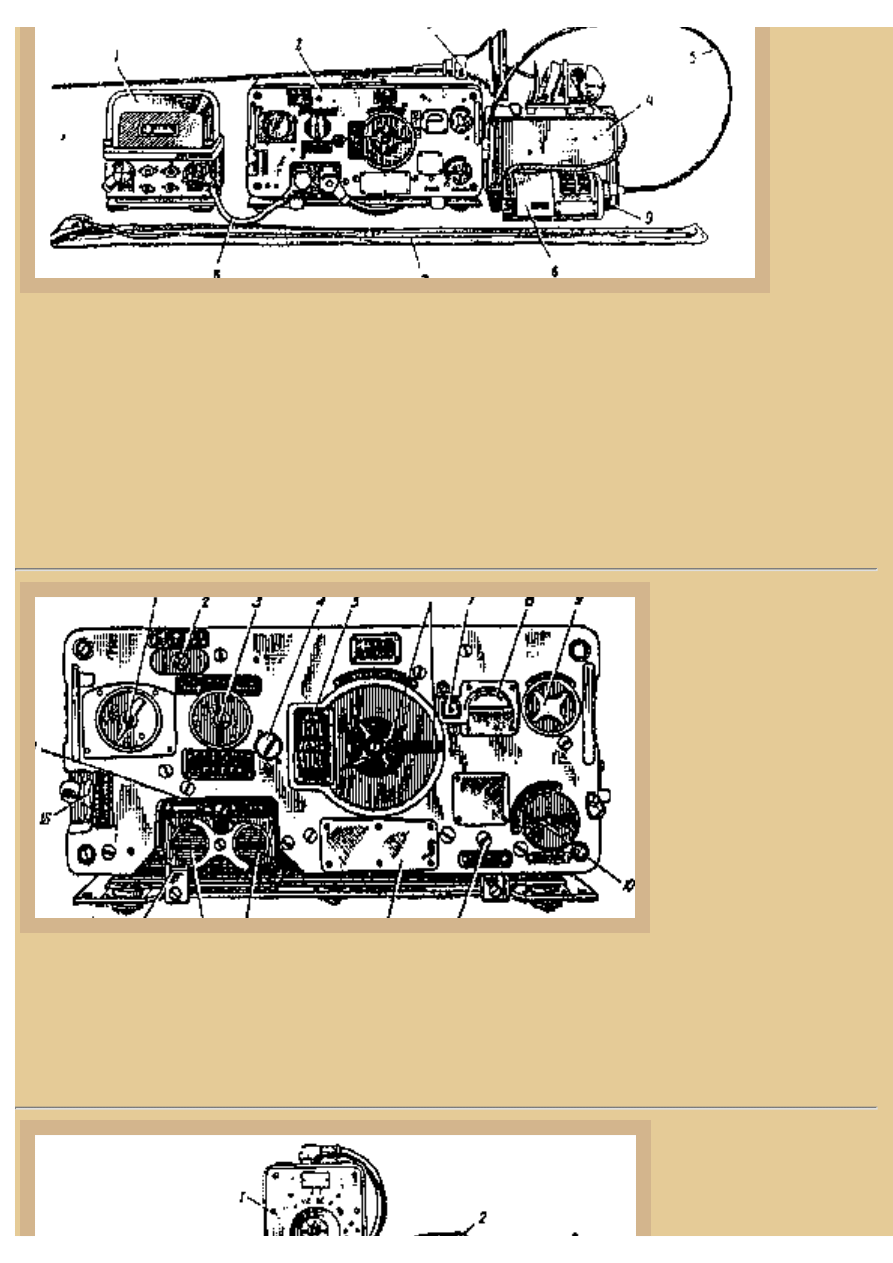
The radio
equipment
carried in
most
Soviet
tanks by
the war's
end
included
this basic
radio setup.
This is the P-113 radio layout, illustrating the most important components of the system. The
transceiver is the large unit in the center and is connected to a power supply amplifier on the left. To
the right is an emergency back-up power supply unit and the 2.5m antenna is seen at the top and its
tuner is laying on its side in front of the emergency power unit. The vehicle antenna is mounted on
the front right corner of the superstructure, directly over the radio position located in front of the
commander. As with most Soviet radios, the typical transceiver could broadcast in AM only out to
around 2.5km. The transceiver operated in the 20-22,375mhz range and with additional power units
the range could be increased up to 20km (P-120 radio set).
Picture 3:
This is the best drawing I
have seen so far of the
primary late WWII
Russian AFV radio
transceiver used with the
P-113. Although robust
for its time, the radio
featured delicate tubes
and often was of little use
during combat. The front
of the radio includes the
primary frequency tuner
in the center of the face
and connections for power and antenna to the lower left. At the upper left is the main power switch
and at the upper right is the antenna control. The radio was shock mounted on rubber feet to a shelf
unit, which was in turn also shock mounted to the vehicle. The radio was painted green and matched
other standard military issue items scattered throughout the white interior.
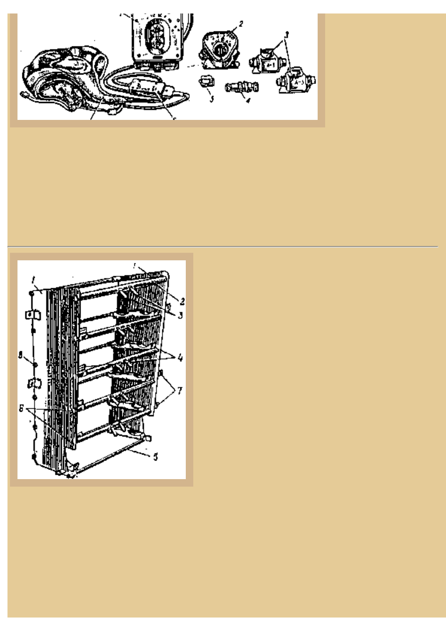
Picture 4:
Additional
file:///H|/Modellismo/AFV%20Interiors/[armor]%20-%20AFV...teriors/afvinteriors.hobbyvista.com/isu152/isu152b.html (2 di 8)06/02/2007 20.08.57
file:///H|/Modellismo/AFV%20Interiors/[armor]%20-%20AFV%20Interiors/afvinteriors.hobbyvista.com/isu152/isu152b.html
communication
equipment is illustrated
here. This appears to be
the simplified tanker's
helmet that appeared in
1941 made of black
canvas, instead of brown
leather, and lightly
padded. There are holes
and pockets at the ears for head phone attachment and the helmet straps and headphone control yoke
cords were generally light buff colored. Crews of ISU-152/122 vehicles were typical tank crewmen,
not artillery drawn units, and they used similar personal equipment and doctrine as other tanks in the
Soviet arsenal at the time. The central box in the illustration is the intercom connection box A-1,
located at each crew position, and was normally green in color. The other various fittings include
crew connect boxes A-2 and A-3 as well as cable connectors for the radio equipment. All would be
painted green or black.
Picture 5:
The shell charge rack on the right side of the AFV was
of a similar construction as the projectile racks on the
left side, but utilized full depth wooden shelf end
supports with indentations for the charges to rest on. The
entire unit was bolted to the right hull wall, over the
sponson, at the back of the compartment. The brass
charge cases were removed by pulling the release tabs
on the cross bars and heaving the shell out of the rack
and, like the projectile racks, this single charge rack held
two shells on each shelf. The additional ten charges were
located on the sponson, forward of the rack (2 or 4
charges) and in a floor rack directly below the gun (6 or
8 charges).
Normal gunnery included identification and ranging to a
target by the commander who called out projectile type
while the driver positioned the vehicle and the gunner
aimed the weapon. Next, the left side loader would open the breech (if not already open) by pulling
on the breech handle which would rotate the breech and withdraw it from the breech ring, and then
slide in the called projectile type. The second loader (on the right) would then ram in the charge with
the breech automatically closing after the shell case. The second loader would hit his ready button on
his side of the howitzer and announce the weapon was up, the commander would command fire, and
the entire interior of the hull would explode with the concussion of the firing of the gun. If it was
silent and the lanyard/percussion firing system did not function, the gunner would reach to his right
and yank the firing lanyard one more time. Once fired, the left loader would open the breech, the
spent charge case would eject and clank to the floor behind the gun, and the sequence would repeat
file:///H|/Modellismo/AFV%20Interiors/[armor]%20-%20AFV...teriors/afvinteriors.hobbyvista.com/isu152/isu152b.html (3 di 8)06/02/2007 20.08.57
file:///H|/Modellismo/AFV%20Interiors/[armor]%20-%20AFV%20Interiors/afvinteriors.hobbyvista.com/isu152/isu152b.html
again, as long as there were targets and the vehicle was not hit in turn.
Picture 6:
The driver's forward position is
located at the left of the hull between
the hull wall and gun carriage/
mount. In this sketch from the
operator's manual the seat is clearly
seen as well as the primary steering
control levers. Clutch and
accelerator pedals are mounted in
their traditional position and a small
instrument panel is bolted to the
front glacis just below eye level. The
front vision flap can be opened or
closed and the resulting vision slit is
protected by multiple layered glass
blocks. To the right of the driver is
the gear shift control lever and
further to the right is the rack for two
compressed air bottles, one stacked
over the other, used to assist starting
the diesel engine on very cold days
or when the batteries were low on
charge. This was accomplished by
the driver turning an air valve to
send a blast of compressed air into
all 12 of the engine cylinders of the
big diesel. This could be done while turning over the engine with the starter motor, or without it,
saving the charge on the batteries and giving the engine crank an extra twist of power. Soviet AFV
designers used this type of assisted starting on most of their diesel power plants but it is generally not
possible for gasoline fueled vehicles because of the delicate balance of the fuel air mixture. A second
control panel is located to the driver's immediate right and contains the electrical system switches,
dials, and fuses, which are accessed behind a small drop-down door. One of the round clamps for the
ammo charges stored under the gun are seen to the right of the unique driver's seat back.
Picture 7:
The driver's seat is an interesting design composed
of a tubular frame with normal padded seat cushion
and an hour glass shaped seat back. The cushions
are held in place by straps and springs, are stuffed
file:///H|/Modellismo/AFV%20Interiors/[armor]%20-%20AFV...teriors/afvinteriors.hobbyvista.com/isu152/isu152b.html (4 di 8)06/02/2007 20.08.57
file:///H|/Modellismo/AFV%20Interiors/[armor]%20-%20AFV%20Interiors/afvinteriors.hobbyvista.com/isu152/isu152b.html
with horsehair, and are covered with brown or
black leather. The seat is adjustable in height by
way of a spring-loaded central telescoping tube
poorly drawn in cross section at the upper left
corner of the drawing. Two side brackets add
lateral support to keep the seat from tipping and are
seen at each side. The seat back can be reclined by
way of the diagonal support adjustment tubes and
can be folded either forward or back for access to
the fighting compartment. This could be handy for
the driver's quick exit in an emergency situation as
there was no over-head hatch for the driver in the ISU-152 (and he could not fit through his forward
viewing flap!). Steering the ISU-152 took a lot of muscle and shifting was a bear, requiring brute
strength to get from first to second gear. Generally, the driver tried to avoid first gear all together and,
if possible, would skip it and start the vehicle rolling in second (on smooth level ground).
Picture 8:
The small forward instrument
panel was bolted to the front
armor plate directly in front of
the driver and contained a
speedometer at the top with
additional oil pressure and
engine/transmission temp gages
to the sides and below. The
panel was painted green or black
with white and black dials. The
driver's electrical panels to the
right of his position came in two
styles illustrated below and were
generally painted the same white
as the interior. In this case you
can see the opened door to the
fuse compartment at the bottom
of each box, and the central
electrical clock is clear in the far
right panel. The switches
controlled power to the various components- the left box controlled the radio, interior lighting,
exterior lights, and gun, while the right panel was for powering engine functions, including the
master power switch.
file:///H|/Modellismo/AFV%20Interiors/[armor]%20-%20AFV...teriors/afvinteriors.hobbyvista.com/isu152/isu152b.html (5 di 8)06/02/2007 20.08.57
file:///H|/Modellismo/AFV%20Interiors/[armor]%20-%20AFV%20Interiors/afvinteriors.hobbyvista.com/isu152/isu152b.html
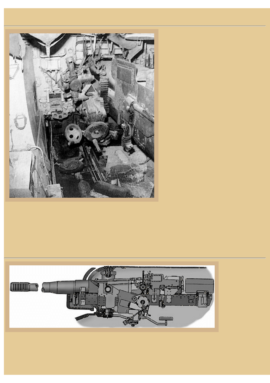
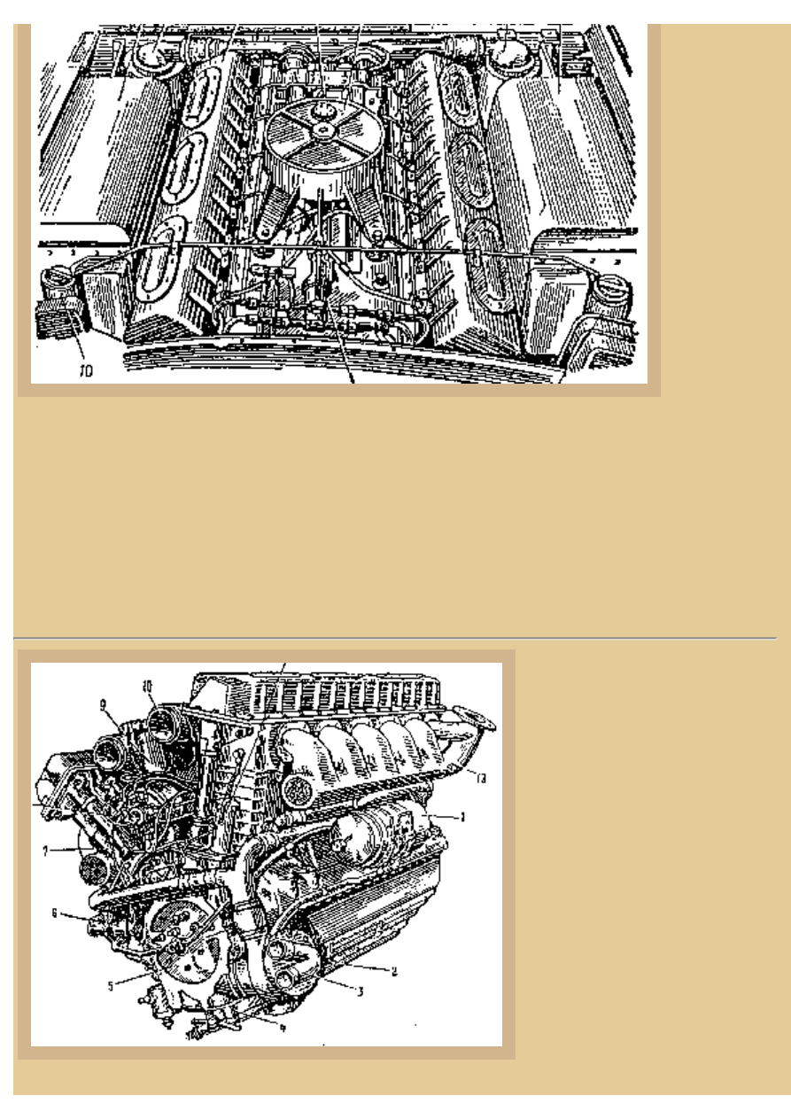
Picture 9:
With the
engine
hatches
removed from
the rear deck
the engine
bay looks like
this for all the
early IS tank
chassis,
including the
ISU-152. We
are standing
on the rear of
the AFV,
roughly on
top of the transmission cover, and looking forward. The engine is the trusty Soviet power plant, the
Model V-2 12-cylinder water-cooled diesel, which develops roughly 520hp at 2,200rpm. In this case
the cylinder heads and valve covers are seen to either side of the block and the can-shaped pre air
cleaners are at the front of the compartment with their large air intake hoses snaking around to the
engine. The large tanks to either side of the engine are radiator water reservoir tanks. The radiators
are actually mounted above the transmission at the very rear of the vehicle, just about under our
position now. With this combination of engine and transmission the ISU-152 was capable of speeds
up to 23mph (37kph) on roads and had a range of around 150 miles (240km) between refueling.
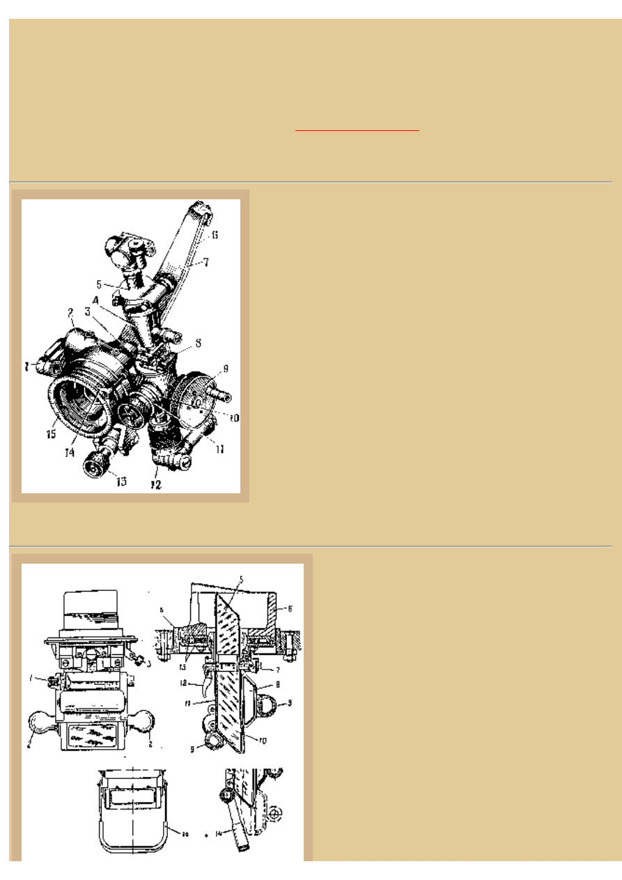
Picture 10:
The front end of the engine is
illustrated in this operator's
manual drawing. The V-2 engine
was a powerful and sturdy unit
and, in one form or another, was
used by the USSR for many years
as their principal tank engine
(Soviet design policy was if it
works, don't change it). Here you
can see the water supply tubes
arriving from the radiators at the
bottom right of the block and
attached to the water pump. From
the pump tubes carry the water
up to the engine, splitting to go to
either side of the block just above
the pump. A cylindrical oil filter
file:///H|/Modellismo/AFV%20Interiors/[armor]%20-%20AFV...teriors/afvinteriors.hobbyvista.com/isu152/isu152b.html (6 di 8)06/02/2007 20.08.57
file:///H|/Modellismo/AFV%20Interiors/[armor]%20-%20AFV%20Interiors/afvinteriors.hobbyvista.com/isu152/isu152b.html
is strapped on this side of the engine and the characteristic tall cylinder heads are apparent in this
drawing. Air inlet tubes leading from the pre air filters are seen at the top of the engine and the
exhaust manifolds snake out both sides at the rear of the engine, directing the exhaust gases out on
each side of the rear transmission deck.
Picture 11:
When the ISU-
122/152 heavy self-
propelled artillery
regiments were
originally formed in
February of 1944, the
vehicles were placed
in groups of 21
assault guns with
four batteries per
regiment. The SP
guns were intended
to support offensive
breakthrough
operations and expected to deal with German strong points and anti-tank defenses from long
distances. First deployed during the summer of '44 offensive "Bagration", the ISU-122/152 regiments
took part in what was probably the largest concentration of Soviet armor up to that time and proved
themselves to be very useful AFVs. After WWII the construction of these assault vehicles continued
and they were sold to other Warsaw Pact member countries as well as Algeria, Egypt and China.
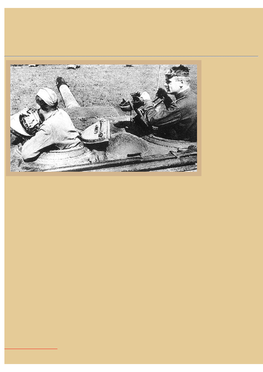
This Soviet News photo illustrates the internal hatch detail of both the gunner's on the left and the
commander's split hatches. The hatch half with the periscope closes first and the second half then
slightly over laps the first and has two small latches at its edge to hold the hatch in place. Normally
there was a leather covered pull chain connecting these latches (as seen on the gunner's hatch) and a
simple pull on the strap would release both latches so you could open the hatch from the inside. The
commander here appears to be holding his cloth tanker's helmet in his left hand while the right rests
on the long handle of his periscope. Notice the antenna base, just forward of his hatch, and also the
domed armor cover over the hull fan, located directly between the two hatches.
The early ISU-152M we have examined here was updated to the last version in 1956, adding more
ammo storage to the new K model for a total of 30 rounds, most of the additional rounds being stored
in a third rack on the left side of the hull. Also added to the ISU-152K was a new TPKU ranging
sight on the commander's cupola and an improved PS-10 telescopic sight for the gunner, as well as a
revised engine and cooling system. My thanks to both Valera Potapov and Steve Zaloga for assisting
with reference information for this page.
file:///H|/Modellismo/AFV%20Interiors/[armor]%20-%20AFV...teriors/afvinteriors.hobbyvista.com/isu152/isu152b.html (7 di 8)06/02/2007 20.08.57

file:///H|/Modellismo/AFV%20Interiors/[armor]%20-%20AFV%20Interiors/afvinteriors.hobbyvista.com/isu152/isu152b.html
BACK TO AFV INTERIORS HOME PAGE
(c) 2001, 2003 AFV INTERIORS Web Magazine
file:///H|/Modellismo/AFV%20Interiors/[armor]%20-%20AFV...teriors/afvinteriors.hobbyvista.com/isu152/isu152b.html (8 di 8)06/02/2007 20.08.57
Document Outline
Wyszukiwarka
Podobne podstrony:
AFV Interiors Water Buffalo
AFV Interiors CV 33 35
AFV Interiors German AFV Radio Equipment In WWII
AFV Interiors M1A2 Abrams
AFV Interiors British Medium Tank Mk I & Mk II
AFV Interiors Czech Light Tank, LT vz 38, Pz Kpfw 38(t)
AFV Interiors Leopard 2
Afv Interiors Daimler Scout Car
AFV Interiors Otter
AFV Interiors B1 bis
Afv Interiors Mk V
AFV Interiors Marder III
AFV Interiors M113 Toa
AFV Interiors Fahrpanzer
AFV Interiors Semovente Da 75 18
AFV Interiors LVT
AFV Interiors IS 2
AFV Interiors Flakpanzer 38t
Afv Interiors Medium Tank Mark A whippet
więcej podobnych podstron