file:///H|/Modellismo/AFV%20Interiors/[armor]%20-%20AFV%20Interiors/afvinteriors.hobbyvista.com/cv35/cv35a.html
Italian CV 33/35 (L.3) Tankette, Part 1
Picture 1:
This first part of
our three-part
examination the
CV 33/35 was
written by a
guest author,
Celso Tondin
Valente of
Brazil. He also
took the color
photographs you
will see toward
the end and also
later in Part 2 of
a tankette that is
preserved at the
Army Academy AMAN Museum in Brazil. Part 3 provides additional interior information, most of which was
sent to us by Pietro Podavini, from Italy. But first, here is Mr. Valente's description of the history and design
of the diminutive CV 33/35 (L.3):
After WWI, the tank was one of the new weapons that received a great deal of attention all over the world, not
only by the combatants that had successfully used it, but also by others that had observed and studied the
conflict. With the exception of the Renault FT-17, all the machines that were produced, or in prototype stage,
were very heavy tanks and very slow because they were designed for short advances across trench lines. Soon
it was clear that the tank must have a greater capacity for range and speed because the lessons of WWI trench
warfare showed static war was a no win involvement, leading only to the complete exhaustion of human and
material resources of each of the combatants.
Quickly, the heavy tank was almost forgotten, except in England, France and the Soviet Union which
continued to produce experimental heavy machines. Only the Soviet Union reached the point of industrial
production and combat use of such vehicles-- these were the Medium Tank T-28 of 35 tons, and the Heavy
Tank T-35 of 50 tons. These tanks had several problems though. Their huge size made them a big target, they
had provided limited visibility for the crew, and they were difficult to operate. They were also very expensive
to build and hard to produce, mechanically complex and difficult to maintain, and not at all reliable. This last
point was the main drawback of these big interwar machines-- technology just wasn't sufficiently advanced at
that time to solve the problem of the great weight and subsequent rolling resistance. In fact, the Russians asked
the Germans for engineering cooperation in order to build the first prototypes and it was based on this
experience they were then able to developed the two vehicles.
The problem with large size and weight in these steel monsters is mainly in the transmission. Of the nearly
sixty T-35 tanks put into action by the Russians during the German invasion of 1941, more than 80% broke
down with transmission problems. It could be said that the founds available for research and development of
new guns and tanks in the inter-war period was very restricted, and money for development of running gear
file:///H|/Modellismo/AFV%20Interiors/[armor]%20-%20AFV%20Interiors/afvinteriors.hobbyvista.com/cv35/cv35a.html (1 di 8)06/02/2007 19.46.35
file:///H|/Modellismo/AFV%20Interiors/[armor]%20-%20AFV%20Interiors/afvinteriors.hobbyvista.com/cv35/cv35a.html
and power plants was consequently also very limited.
As a result, research and prototype production was directed toward the opposite side of the tank family, to
light and faster tanks. These, by their low cost, ease of production, mechanical simplicity and operation, had
created a great interest in several countries. At that time, everybody wanted tanks to train their troops and to
try out new combat tactics. England became the prominent country in this field between the wars-- the British
were basically responsible for continuing the development of the light and fast tank concept in the 1920s.
Eventually, a specific name was created for this kind of small machine, "tankette". The British firm of Carden-
Loyd produced several models of tankettes that were exported with success to many countries. These British
tankettes were the inspiration for several models subsequently produced in France, the Soviet Union, Italy,
Poland, Czechoslovakia, Sweden, and Japan. More than twenty-five countries eventually produced, copied, or
bought these machines directly from England and they had a long lasting effect on tankette design.
With the same speed they had became popular, the smaller machines became obsolete for combat as new
doctrines for warfare were developed and the technological evolution of anti-tank weapons in the 1930s
progressed. Originally produced in large numbers, the tankettes had quickly become impractical. With the
possible exception of the Abyssinian (Ethiopian) Campaign 1934-36 where the Italians used some 150 of such
machines with success, all the remaining conflicts before WW II, including the Spanish Civil War, Japanese
invasion of China, and the Soviet-Japanese incident, clearly showed this equipment to be obsolete. Anyway,
when WW II began, anything at hand was used and the tankettes that existed in large numbers were placed in
combat. By 1941 all Italian tankette production had ceased, most of the machines having been destroyed or
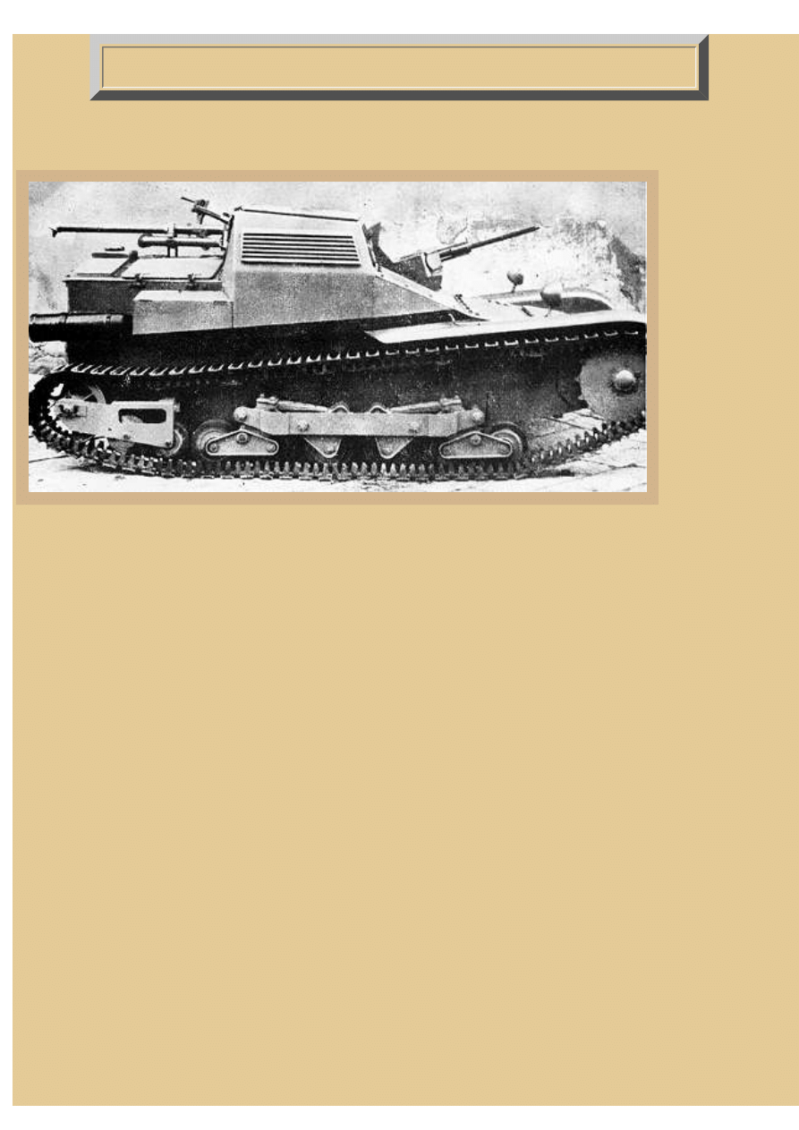
taken out of service from the front lines with great joy by the crews! This is a prototype of the CV 33,
equipped with a single air-cooled FIAT Model 35 6.5mm machine gun. Notice the riveted and welded hull and
the twin track tension adjustment rollers mounted on the same large bracket used for the rear idler. Although
the two track tension rollers will be reduced to only one on each side during series production, the common
mounting bracket and other design elements will remain the primary identifiers of all the early CV 33
tankettes.
Picture 2:
Tankette CV 33:
During WW I,
Italy received
from France one
Schneider tank
and several
Renault FT-17
tank for
examination. A
deal was made by
which FIAT
began to produce
their version of
the FT-17, with
some
modifications for
the use of Italian components like motor, weapons, armor, etc. This machine was called the FIAT 3000 (Carro
Armato M21) and around 100 were produced beginning in 1919. In 1928 it was slightly modified and the
vehicle then called the FIAT Ansaldo 3000B. The Italians used these two models for several years and, at the
file:///H|/Modellismo/AFV%20Interiors/[armor]%20-%20AFV%20Interiors/afvinteriors.hobbyvista.com/cv35/cv35a.html (2 di 8)06/02/2007 19.46.35
file:///H|/Modellismo/AFV%20Interiors/[armor]%20-%20AFV%20Interiors/afvinteriors.hobbyvista.com/cv35/cv35a.html
end of WW II, they were still in active service for airport protection and policing duties. In the 1920s, a few
different design prototypes were created in Italy and others bought from outside nations, but none were
accepted for series production.
In 1929, some British Carden-Loyd Mark VI Tankettes were bought from England for examination and
experiments and after testing a deal was signed allowing Italy to produce some of their own. Ansaldo, using
motors and transmissions from FIAT, produced 25 of these Mark VI tankettes and named them CV 29.
Armament consisted of one Revelli Model 1914 water-cooled 8mm machine gun.
With additional experience the CV 29 tankette was further modified and the resulting machine named the CV
3, which was tested by the Italian Army in 1931-32. The new tankette was approved for production and named
Carro Veloce (fast tank) CV 33. The first lot was planed for 1300 vehicles, 1100 with FIAT Model 35 6.5mm
machine guns and 200 with short 37mm cannons. In reality, only 300 of the machine gun versions were
produced by FIAT-Ansaldo, these known as Serie I. The FIAT Model 14 MG was nothing more than the
Revelli Model 1914 MG modified for air-cooling and produced in the same 6.5mm caliber. This was not a
successful gun, it was in fact worse than the Model 1914, for unlike the Model 1914 it fired from a closed bolt
with resultant cookoffs of ammunition after periods of sustained fire when the weapon was hot. This gun
earned the nickname of 'Knuckle-buster' because of the hazardous proposition of clearing out the gun when a
cartridge was jammed in a hot barrel. In 1935, Serie II of the CV 33 was produced and it differed from the
proceeding models by the installation of two FIAT 18/35 8mm machine guns instead of the one FIAT 6.5mm
MG. Serie II also used a modified track tension wheel that was mounted on its own simplified bracket that was
separate from the idler wheel bracket. After the successful use of the twin FIATs MGs, all Serie I vehicles
were changed to Serie II type by installing the two 8mm FIAT 18/35 machine guns.
In 1933/34, the CV 33 was modified yet again, this time the upper structure armor was bolted together with
conical bolts instead of the prior combination of welding and riveting. Twin 8mm Breda 38 machine guns
were used in the mantlet in front of the commander/gunner, although FIAT Model 35 8mm machine guns were
also still used when necessary. At this time the vehicle was renamed CV 35, the 35 standing for the year of
introduction to the troops. One source claims that the CV 35 weapon was a single 13.2mm Breda MG, but
there seem to be other weapons utilized also, including the twin Breda 38 set up. The last variant in the line
was called the L 3/38 and included a new suspension utilizing, I believe, torsion bars, but I believe that this
design was primarily exported to Brazil. These tanks might also have been mostly armed with twin 8mm
Madsen machine guns. In 1938 the original designation of CV 33 was changed to L-3-33 and the CV 35 was
changed to L-3-35, the vehicles often seen in popular writing lumped together as L-3-33/35, or simply L-
33/35.
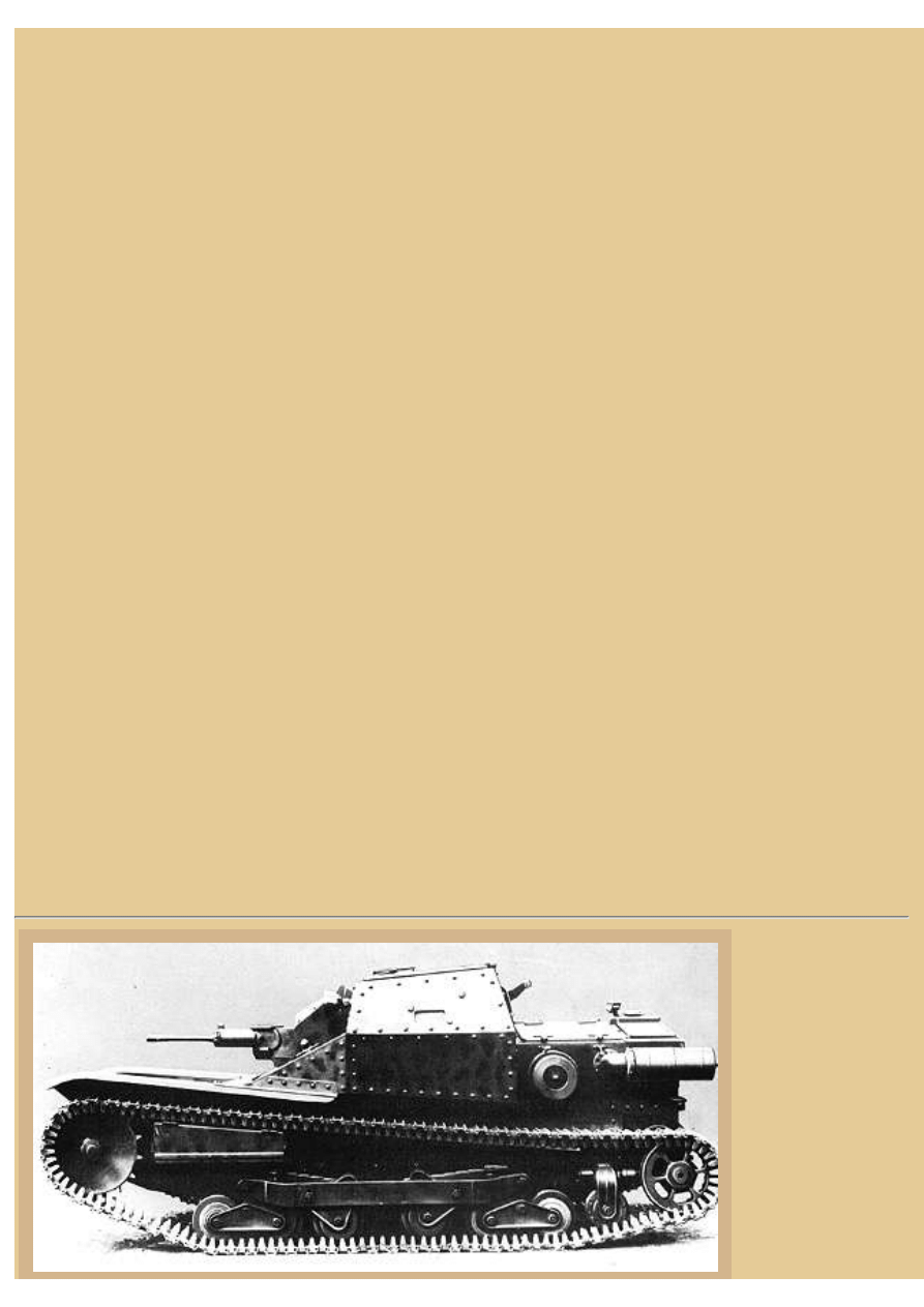
Picture 3:
Technical
Characteristics:
All CV 33 tankettes
were built with
hardened steel plates
riveted and welded
on a frame structure
in which the
mechanical
components were
attached. The
file:///H|/Modellismo/AFV%20Interiors/[armor]%20-%20AFV%20Interiors/afvinteriors.hobbyvista.com/cv35/cv35a.html (3 di 8)06/02/2007 19.46.35
file:///H|/Modellismo/AFV%20Interiors/[armor]%20-%20AFV%20Interiors/afvinteriors.hobbyvista.com/cv35/cv35a.html
construction of CV
35 was simplified
when the plates were bolted together using a special conical head bolt as you see here on this production CV
35. The thickness of the armor was 14.0mm in front, 9.0mm on the sides, and 7mm in the back, and this
protection was good only against light infantry bullets of 8mm caliber and splinters of cannon shells that
exploded at some distance.
The motor was a FIAT SPA CV3-005 with four cylinders and it was transversally mounted in the rear
compartment, the motor specifically designed for use in tanks. The transmission axle traversed from the rear to
the front of the vehicle and was there connected to the forward mounted gearbox, a four-speed manual with a
dual range reduction. In front of the gearbox was the reduction box with the clutches and brakes necessary to
drive the vehicle. The front sprocket and one adjustable idler wheel in the rear held the track, the vehicle riding
on seven rubber wheels. Of these, six were assembled in boogies with laminated springs. There were no return
rollers and the track itself was composed of 72 pairs of forged steel links. The first track of the pair was the
main link, covered with rubber, and the second was the joining link. Steel pins held the track shoes together.
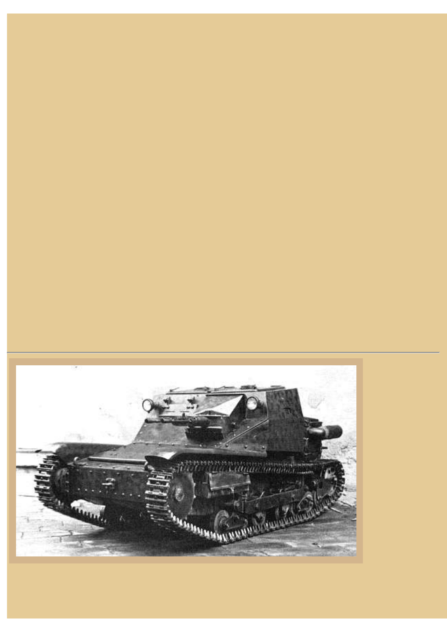
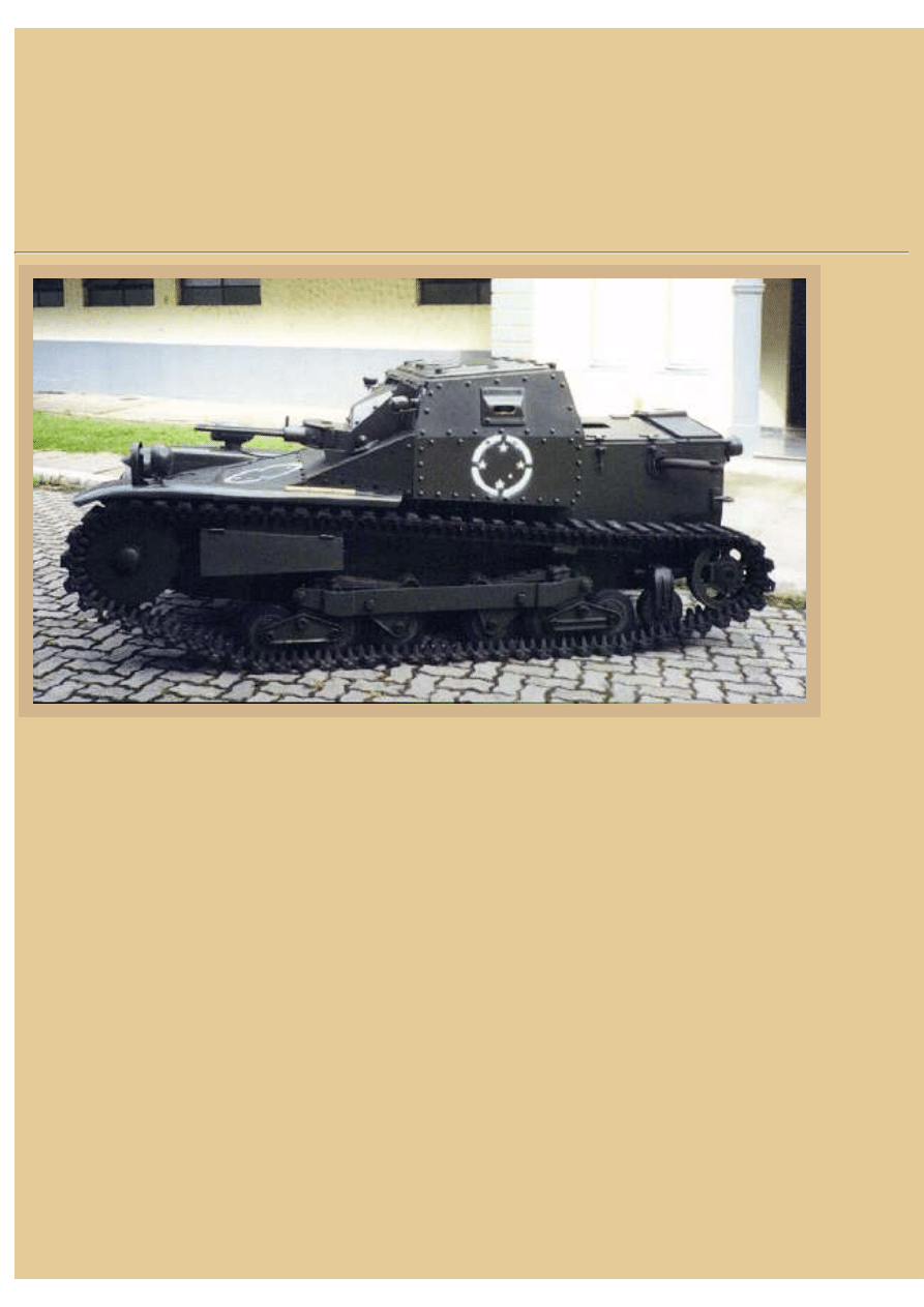
Picture 4:
Two access doors on the top of
the hull structure allowed entry
and exit of the driver and
commander. The driver's seat was
at the right side and had all the
controls at hand. The commander/
gunner's seat was on the left side
and he operated the weapons, the
gun mantlet allowing a limited
elevation of +15º to -12º and
traverse of 12º each side of center.
Sighting was accomplished via a
hole in the mantlet between the
guns that was fitted with a
telescope. Internal space was very
limited; a tall person certainly had
problems with head space. Vision
directly forward, to the rear, and to the sides was possible by the use of several apertures that could be closed
from inside the vehicle. In the two hatches on top there were two fixed periscope apertures. There was no
provision for a radio, but one could be fitted to command vehicles if necessary. This is a CV-35 with bolted
hull photographed during the Spanish Civil War period. Notice the single track tension roller just in front of
the idler wheel that replaced the dual unit with large mounting toward the end of the CV 33 production run.
file:///H|/Modellismo/AFV%20Interiors/[armor]%20-%20AFV%20Interiors/afvinteriors.hobbyvista.com/cv35/cv35a.html (4 di 8)06/02/2007 19.46.35

file:///H|/Modellismo/AFV%20Interiors/[armor]%20-%20AFV%20Interiors/afvinteriors.hobbyvista.com/cv35/cv35a.html
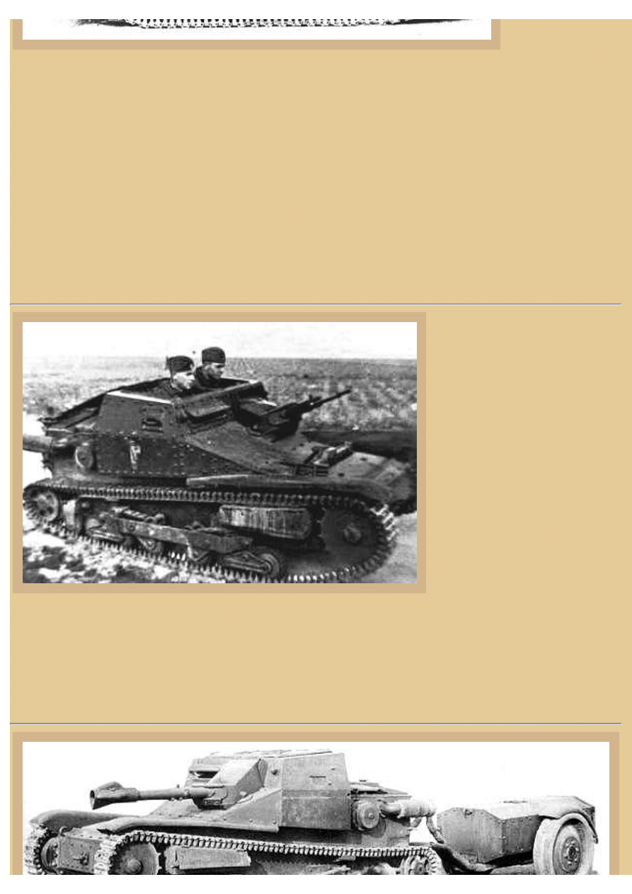
Picture 5:
Variants:
The CV 33 hull was utilized for several other functions. The first was the Carro Lancia Fiamme, seen here,
where one or both of the twin machine guns was exchanged for a flame-thrower. In the first models of this
vehicle, the fuel tank for the flame-thrower was assembled over the rear deck and had a capacity of around 60
liters. Soon it was discovered that this was insufficient and a two-wheeled trailer with 500 liters jellied
gasoline capacity was towed behind the tankette. The flame-thrower had a range of 100 meters and was used
several times in the Abyssinian campaign and also again in North Africa. A communication tankette, named
Carro Radio, had a radio with the antenna fixed on the rear engine deck. A prototype of a maintenance tankette
was made, Carro Veloce Recupero, but it was never used. A bridge layer, Passerella, towed a trailer with a 7m
bridge in four parts; the crew had to leave the vehicle in order to assemble the bridge, but it took only ten
minutes. Some of the CV 33/35 vehicles had their main armament changed to a Swiss Solothurn 20mm
antitank cannon, S18-1000, which fired an armor piercing shell at 750m/s (2.460 ft/s) and these are seen most
commonly in North Africa. At least one CV 35 had its superstructure removed and had a 47 mm antitank
cannon placed inside, named Semovente L 3 47/32. But it, too, apparently never saw combat use.
Production:
There were approximately 2,500 CV 33/35 vehicles produced between 1932 and 1941, and of these around
200 were exported. The countries included Afghanistan, Albania, Germany (a few in 1943-44), Austria,
Bolivia (re-exported to Brazil), Brazil (23 units in 1938), Bulgaria (14 units in 1934), China (20 units in 1936),
Spain (during and after the Civil War), El Salvador, Greece, Hungary, Iraq, Yugoslavia and Czechoslovakia.
Combat use:
The first and only effective use of the CV 33 was in the Abyssinian campaign in 1934. Both the lack of roads
and the opposition being composed of a medieval army were important factors for the success of the vehicle
and its use by the Italians. Even though the small vehicles were of seemingly limited value, the Ethiopians
hadn't anything to use against them except their rifles and light machineguns, and sometimes spears and
arrows! Most of the Ethiopians had never seen a tank before, and to combat the Italian CV 33 they encircled
the tank in a human mass, trying to hit the eyes of the crew with knifes through the vision slots. They also
attempted to lock up the track with pieces of wood, or pour gasoline (when available) on them and ignite them.
Near the end of the campaign the Ethiopians managed to successfully destroy or capture 13 CV 33 tankettes.
Only two Italians survived this particular battle, bailing out of their tankette and putting their hands up,
shouting "Cristo! Cristo!" The other crews surrendered and also raised their hands, but the Ethiopians didn't
know this was an act of surrender and thought instead that it was just easier to hit their human targets! The
first two crewmen stayed alive only because the attackers were Coptic Christians and knew the word "Cristo"!
By the end of the campaign it was clearly demonstrated that at even as this early date the CV 33 could do very
little against reasonably equipped and trained troops.
The next war where the CV 33/35 was used was the Spanish Civil War, where the Corpo Truppe Volontarie,
sent by Mussolini, used the tankette in good numbers. The result was a fiasco; it was no opposition against the
Nationalist tanks, specially the Russian T-26 that had heavier armor and a 45mm cannon as main armament.
Even with all its limitations, the CV 33 was still often used and a particularly heroic action occurred when a
file:///H|/Modellismo/AFV%20Interiors/[armor]%20-%20AFV%20Interiors/afvinteriors.hobbyvista.com/cv35/cv35a.html (5 di 8)06/02/2007 19.46.35
file:///H|/Modellismo/AFV%20Interiors/[armor]%20-%20AFV%20Interiors/afvinteriors.hobbyvista.com/cv35/cv35a.html
CV 33 flame thrower tankette attacked a Russian T-26 from the rear; the attack continued until the Russian
tank traversed its turret and fired point blank. The crew of the CV 33 received postmortem medals for bravery.
During the Second World War, the CV 33/35 was used in all the Italian campaigns-- France, Greece,
Yugoslavia, Albania, Crete, North Africa, Russia, Corsica, Sardinia, Sicily and Italy. In all these theaters the
losses of tankettes was appalling, they had no chance in a fight against any of the medium tanks used by the
enemy.
Picture 6:
In Brazil:
Brazil
received
a number
of CV
35s in
1938 to
be used
in place
of the
Renault
FT-17
that had
been
adopted
back in
1921.
The CV
35 was not classified as Carros de Assalto like the Renault had been, but Autometralhadoras, a name often
used at that time and of French origin. Here in Brazil they were always referred as "Ansaldo". With the
program to modernize the Army at that time the target was to have one regiment of Autometralhadoras in each
cavalry division, with two companies of 20 vehicles each.
The historian Adler Homero Fonseca indicates that Brazil received only 23 vehicles; 17 armed with two
Madsen 7mm machineguns, three armed with one Breda 13.2mm machine gun, and three command cars
without guns. All remained in Rio de Janeiro and were used only for training until they were replaced in 1942
by American M3 Stuart light tanks. Two different sources indicate that the CV 35 tankettes were restored(?)
by a company in Rio in the 1950s and re-exported to Bolivia; one of the sources indicates that they were sent
to that country without armament as "agricultural tractors". Another source says the CV 35s were assigned to
an Armoured Training Squadron at the Escuela de la Motorisation (1 x HQ Platoon and 4 x Tank Platoons)
and the HQ tank of each platoon was armed with 1 x 13.2 mm HMG, while the others were armed with 2 x
7mm Madsen MGs. In 1948 they are said to have been handed over to the Dominican Republic. Take your
pick of story.
In Brazil today there are four samples of these Tankettes still in existence, one on display in the cavalry
section of the Military Academy of Agulhas Negras in Resende, and another in running condition at the
Ordnance section of the same academy. In Deodoro, Rio, there is one tankette used as a monument in a
cavalry quartel, and the last CV 35 in Brazil is in running condition in the AFV Army Museum. We believe
that these two CV 35 in running condition are the only two in the world, although one of them has a Ford
file:///H|/Modellismo/AFV%20Interiors/[armor]%20-%20AFV%20Interiors/afvinteriors.hobbyvista.com/cv35/cv35a.html (6 di 8)06/02/2007 19.46.35
file:///H|/Modellismo/AFV%20Interiors/[armor]%20-%20AFV%20Interiors/afvinteriors.hobbyvista.com/cv35/cv35a.html
tractor engine in place of the original engine.
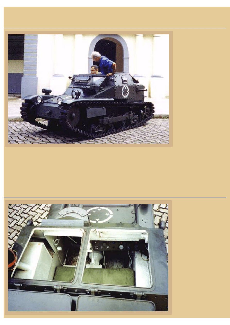
Picture 7:
Test drive:
We had the chance to
make a short test drive
with the CV 35 by
special permission of
Major Luiz Antônio
Duizit de Brito of the
Ordnance Section of the
Army Academy AMAN.
It is not a common
opportunity to find the
chance to test drive such
a rare vehicle; it was
amazing. The tankette is
in very good condition
and shows very little use,
however maintenance
troubles and lack of spare
parts led to changing the original motor. A Ford four cylinder is now in place and to use it required some
internal modifications so as not to alter the external appearance of the tank. We saw when we looked inside
that not only was the motor changed, but so was the radiator, fuel tank, and armored protection of the radiator,
muffler and electrical equipment. The exterior was painted in the old pattern of the Army, and new headlights
and a siren were mounted. All the rest of the vehicle is completely original in components and operates
normally.
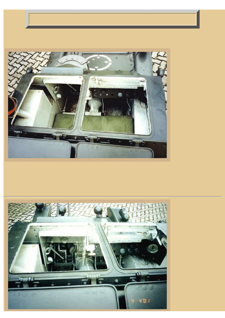
Picture 8:
Access to the interior is
easy due to the two large
hatches in the top of the
superstructure. Internal
space inside is just
enough for two small
persons. The driver's
position is like you would
expect from a vehicle of
this size and vision is
very limited. The lack of
a turret for the weapons is
the main problem for the
commander/gunner, he is
lacking adequate vision
and direction of fire for
the guns. The seats in this
file:///H|/Modellismo/AFV%20Interiors/[armor]%20-%20AFV%20Interiors/afvinteriors.hobbyvista.com/cv35/cv35a.html (7 di 8)06/02/2007 19.46.35

file:///H|/Modellismo/AFV%20Interiors/[armor]%20-%20AFV%20Interiors/afvinteriors.hobbyvista.com/cv35/cv35a.html
vehicle are not original
and we believe that they originally had at least two height positions because we have seen several period
pictures where the crew have their heads out. This is impossible with the current seats. The original Madsen
machine guns were removed because the vehicle is only a display piece, but in place the museum has placed
two Madsen barrels in the mantlet.
Our thanks to AMAN for the opportunity to examine their vehicle and to Major Luiz Antônio Duizit Brito
who is responsible for the Ordnance Section.
Respectfully,
Celso Tondin Valente
ctvalente@uol.com.br
Bibliography:
Christopher F. Foss, "Illustrated Encyclopedia of the World´s Tanks and Fighting Vehicles", Salamander
Books, 1978.
A. J. Baker, "A Conquista da Etiópia", Editora Renes, 1979.
Several sites on the internet:
AFV Museum Bovington - England
AFV Museum Samur - France
Historia dos Blindados Italianos - Itália
AFV News
This concludes the first part of our exploration of the Italian CV 33/35 tankette. Part 2 will continue with our
examination of this preserved tankette's interior.
TO ITALIAN CV 33/35 TANKETTE PART 2
TO ITALIAN CV 33/35 TANKETTE PART 3
BACK TO AFV INTERIORS HOME PAGE
(c) 2001, 2003 AFV INTERIORS Web Magazine
file:///H|/Modellismo/AFV%20Interiors/[armor]%20-%20AFV%20Interiors/afvinteriors.hobbyvista.com/cv35/cv35a.html (8 di 8)06/02/2007 19.46.35
file:///H|/Modellismo/AFV%20Interiors/[armor]%20-%20AFV%20Interiors/afvinteriors.hobbyvista.com/cv35/cv35b.html
Italian CV 33/35 (L.3) Tankette, Part 2
Picture 1:
This is the second part
of a three-part series on
the Italian CV-33/35
tankette. We will
continue now with some
additional description of
the modified AMAN
Museum vehicle using
additional photographs
of that machine
provided by Celso
Tondin Valente. As Mr.
Valente mentioned,
much of the interior has
been altered in this
tankette, especially
inside the engine
compartment. The gas
tank you see to the left,
next to the commander/gunner, is also not original. The tank was originally located back to the right behind
the driver, but was moved here when the Ford engine was added. Normally, this side sponson held a large
wooden bin for MG ammo magazines, all within easy reach of the gunner.
Picture 2:
A slightly different
angle through the over-
head hatches provides
some detail of both crew
positions. Directly
forward of the
commander/machine
gunner is the mount and
mantlet for the twin
MGs, in this case the
vehicle was fitted with
Madsens. You can also
see the transmission on
the floor between the
two positions and some
of the instrument panels
file:///H|/Modellismo/AFV%20Interiors/[armor]%20-%20AFV...0Interiors/afvinteriors.hobbyvista.com/cv35/cv35b.html (1 di 7)06/02/2007 19.46.36
file:///H|/Modellismo/AFV%20Interiors/[armor]%20-%20AFV%20Interiors/afvinteriors.hobbyvista.com/cv35/cv35b.html
in front of the driver to
the right. The driver
also has a very large vision flap in front and it is shown here in the open position.
Many of the Italian CV 35s mounted the Breda 38 8mm (0.315in) machine gun instead of the Madsens, and
as you may recall, the famous Italian Breda used in their armor vehicles was merely an adaptation of their
successful infantry MG. The weapon was very similar to their 13.2mm Breda aircraft gun and included a
couple of interesting features. For instance, the cocking handle can be attached to either side of the receiver
and when the magazine is empty it is pitched forward. Also, the gas regulator had at least 10 different
settings, and the gun had a very pronounced muzzle flash. Ammunition was by a vertical box feed, each
magazine holding around 21 rounds. The guns would have taken a good deal of space in front of the
commander with ammo piled to his left on the sponson.
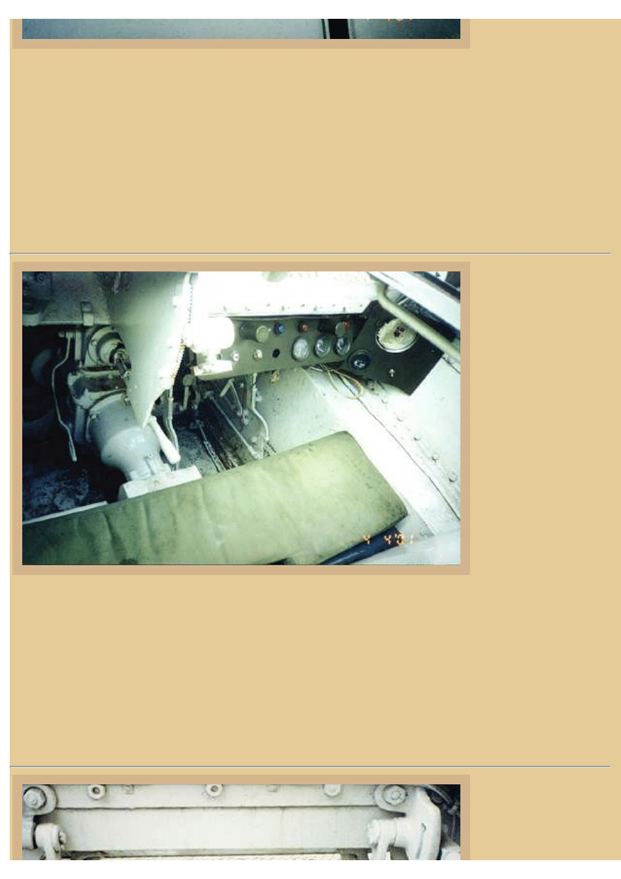
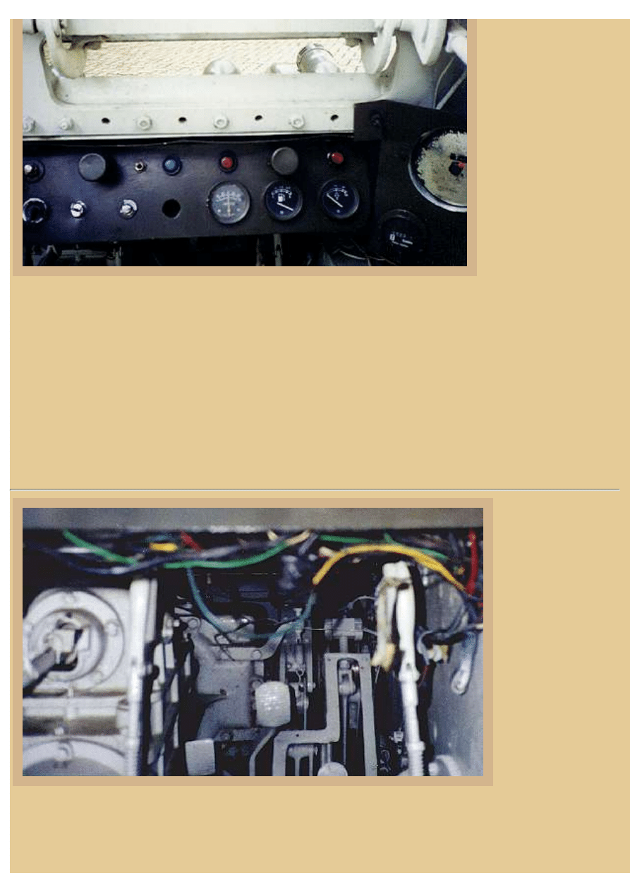
Picture 3:
Here is a view of the
driver's position in this
museum vehicle and his
vehicle controls. The
transmission and
gearshift lever are at the
left and you can see
some of the steering
levers rising from the
floor in front of the seat.
I don't believe that
either of the instrument
panels seen here is
original, although the
one to the right is
similar to the size and
location of the original.
Typically, this main
wooden instrument
panel would contain the large graduated tachometer with a red reference band that indicated high revolutions.
Also on the panel were an oil pressure gage and emergency light, the primary lighting switch, and the key
starter.
The driver also had a wooden MG ammo rack on the sponson to his right, but it was smaller than the one
next to the gunner and is completely missing here. The engine was water cooled, and the connections
between the engine block and radiator were notoriously poor. The constant leaking led to the vehicle's bad
reputation of requiring frequent water refills, not necessarily a positive trait when used in the Ethiopian and
North African deserts.
Picture 4:
This is a close-up shot
of the driver's armored
visor, the actuating
file:///H|/Modellismo/AFV%20Interiors/[armor]%20-%20AFV...0Interiors/afvinteriors.hobbyvista.com/cv35/cv35b.html (2 di 7)06/02/2007 19.46.36
file:///H|/Modellismo/AFV%20Interiors/[armor]%20-%20AFV%20Interiors/afvinteriors.hobbyvista.com/cv35/cv35b.html
handle just visible to the
far right. When closed,
the he could view
forward only through
thin slots machined in
the visor, or possibly
through the small
periscope in his over-
head hatch, and to the
side only through two
additional vision slots
on the side armor. When
the front visor was open
his view was very good,
but there was no bullet-
proof glass block behind
the vision slits in the visor when it was closed and therefore no protection from bullet splash.
As we mentioned earlier, the first real Italian armor action utilizing the tankettes occurred in East Africa in
the spring of 1936, when around 500 tanks and tankettes were used in the Abyssinia campaign. Tanks and
tankettes were also sent along to Spain to fight for Franco during the Spanish Civil War and many were lost
in furious battles against Russian T-26 tanks and anti-tank guns. By 1937 a new tank unit had been formed,
this one called a motorized brigade, and it included one tank regiment, four light battalions, a motorized
Bersaglieri regiment, two anti-tank companies, an antiaircraft battery, and an engineer company. This unit
was named the 1st Armored Brigade and it would be the pattern around which future tank units would be
designed.
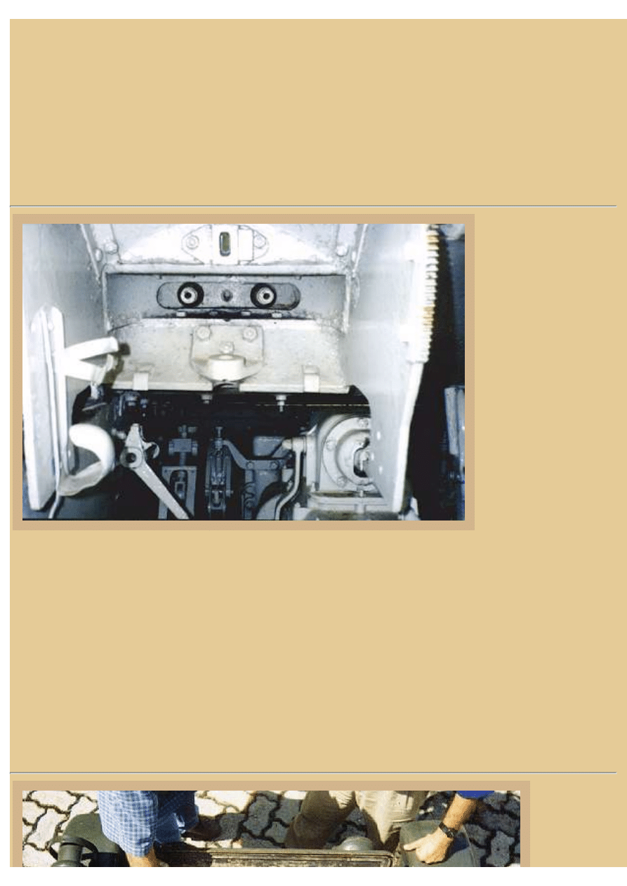
Picture 5:
Although not perfect,
this view under the
instrument panel
provides some
understanding of the
controls down here.
To the far left is the
transmission and its
shifting lever. The
two steering levers
are seen to either side
of the driver's leg
area, the levers
connected to an
epicyclic clutch
steering gear and
final drive unit
attached to the front of the transmission and barely visible forward of the pedals here. The pedals include the
brake, accelerator and clutch, and some of their connecting rods are visible. A sheet metal plate would
normally be attached to the frame you see in front of the accelerator pedal to the right, but it is missing here.
file:///H|/Modellismo/AFV%20Interiors/[armor]%20-%20AFV...0Interiors/afvinteriors.hobbyvista.com/cv35/cv35b.html (3 di 7)06/02/2007 19.46.36
file:///H|/Modellismo/AFV%20Interiors/[armor]%20-%20AFV%20Interiors/afvinteriors.hobbyvista.com/cv35/cv35b.html
Once the 1st Armored Brigade had been formed, the 2nd Armored Brigade was created. By February of 1939
the 2nd Armored Brigade had became the 132nd Armored Division, also called "Ariete." The next month, the
1st Armored Brigade became the 131st Armored Division, named "Centauro." By the end of the year the
133rd Armored Division had also been formed, and it was called "Littorio". These armored divisions
typically had the following organization-- one tank regiment with four battalions, one Bersaglieri regiment,
one motorcycle battalion, one trucked (mobile) infantry battalion, one motorized artillery regiment, one
antiaircraft troop, and one engineer company. In most cases the divisions at this time (early 1940) contained
only one light (tankette) and one medium tank battalion.
Picture 6:
The mount for the twin
MGs is seen directly
forward of the
commander/machine
gunner's seat, but the
gun mount and guns are
missing. You can get
some feel for the look of
the twin Breda 38 guns
from the pictures in the
M13/40 page elsewhere
in AFV INTERIORS,
but I am still looking for
illustrations of the
Madsens used in these
Brazilian machines. The
telescopic sight would
mount in the hole you
see between and above
the barrel holes; the MG barrel holes are plugged by dummy barrels sticking out the front of the mantlet. To
our right is an empty portable fire extinguisher bracket, and down below is the transmission and gearshift
lever to the right and left brake lever control rods down and forward near the foot area.
In the summer of 1940, Italy invaded southern France, and Italy's armored units were subsequently handed
heavy casualties by the French Alpine division's tanks. By this time, most of the Italian armor was composed
of around 1,300 tankettes, along with approximately two dozen light tanks and around one hundred M11/39
medium tanks. To help make up for their reduced numbers, the Italians had added two armored battalion
groups by the end of the 1940, these formed to fight in the North African desert. Ariete was the first division
to receive the new M13/40 tanks, but still most of its tank strength was CV 33 and 35 tankettes. In August of
1941, the Corpo d'armata di Manovra (the Mobile Army Corps) was created by combining Ariete and Trieste
motorized infantry divisions along with an armored reconnaissance unit.
Picture 7:
If you look
down at the
top of the
file:///H|/Modellismo/AFV%20Interiors/[armor]%20-%20AFV...0Interiors/afvinteriors.hobbyvista.com/cv35/cv35b.html (4 di 7)06/02/2007 19.46.36
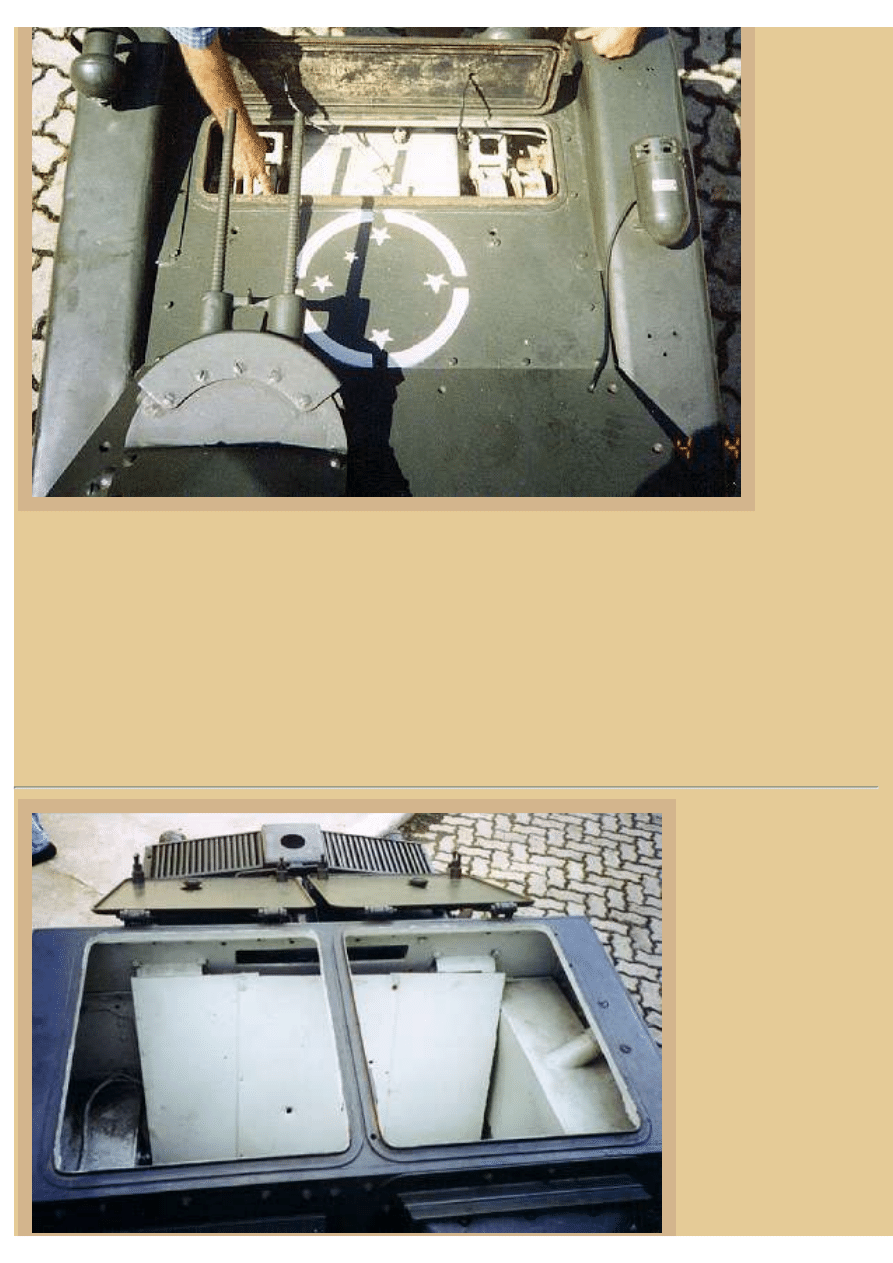
file:///H|/Modellismo/AFV%20Interiors/[armor]%20-%20AFV%20Interiors/afvinteriors.hobbyvista.com/cv35/cv35b.html
forward hull
while
standing in
the open
hatches, you
can see the
open access
cover for the
epicycles and
brake drums.
The mantlet
for the twin
Madsens is to
the lower left
and the
dummy
barrels are
visible. The
bolted
construction
of the CV 35
armor is also apparent here.
The 8mm Madsen light machine gun was developed in Denmark by Captain W.O. Madsen of the Danish
Artillery. It was recoil operated and had a rate of fire of around 450rpm. The basic machine gun could be
ordered in a number of different calibers and it was sold to many countries, including the Russians, who
subsequently used it extensively in the Russo-Japanese War. It was a remarkable weapon, operating unlike
any other machine gun of the time. However, it too was fed from an over-head magazine. After WWII, the
company changed its name to Dansk Industrie Syndikat and began manufacturing submachine guns, but then
had to retire from the firearm business in 1970 due to poor sales.
Picture 8:
The view looking to the
rear of the
superstructure shows a
multi plate sheet metal
seat back separating the
engine compartment
from the crew
compartment. To our
right is the new fuel
tank again, and above
what I assume is the
seat back is an opened
viewing flap that
probably helped to
exhaust fumes produced
by the firing MGs. I
file:///H|/Modellismo/AFV%20Interiors/[armor]%20-%20AFV...0Interiors/afvinteriors.hobbyvista.com/cv35/cv35b.html (5 di 7)06/02/2007 19.46.36
file:///H|/Modellismo/AFV%20Interiors/[armor]%20-%20AFV%20Interiors/afvinteriors.hobbyvista.com/cv35/cv35b.html
don't believe the seat
back sheet metal is
original as it completely blocks the two vision slits on the back wall. Although it has been written that the
over-head crew hatches could hold periscopes for the commander and driver, I think these openings are just
signal ports as they seem to me to be too small for a periscope, unless they were very small units indeed.
Near the end of 1941 the "Littorio" division was also sent to North Africa and combined with a three-
battalion M13/40 regiment (which included two groups of Semovente 75mm assault guns), two desert patrol
units, support elements, an extra recon group of Besaglieri, and a group of L6/40 light tanks. Unfortunately
for the Italians, this combined unit did not see action as the infantry were annihilated in transit and many of
the other components were stripped for replacements for the divisions already in place. The Ariete was also
restructured into this new structure but both divisions were more or less destroyed during the fighting at
Alamein.
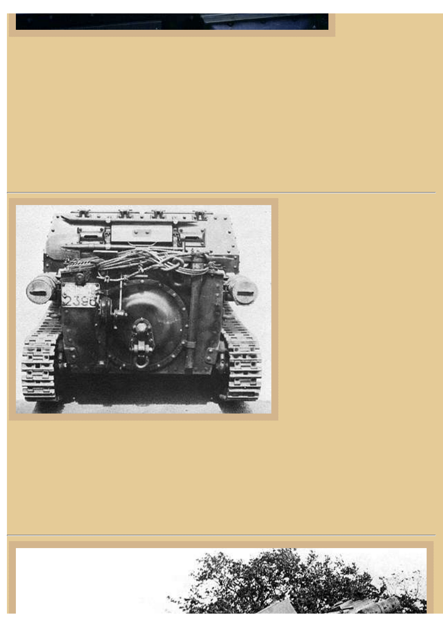
Picture 9:
The view from the rear of a CV 35
shows the same vent flap (on the back
wall over the firewall) with vision slots
to either side. There was just enough
room in the engine compartment for
the SPA CV3 engine, fuel tank, and
radiator/fan, and you can see the
exhaust mufflers mounted outside on
either side of the hull. The SPA CV3
was a 4-cylinder, in-line gasoline
engine of 62 liters swept volume that
produced approximately 43hp at
2,400rpm. With the 62 liters in the fuel
tank, the tankette had a cruising range
of roughly 120km on roads. Speed was
approximately 42kph on roads and
15kph cross-country. I think the large
round hatch on the rear armor plate is
the housing for the circular fan used to
cool the radiator and engine compartment, but at this time I have not located images of the engine or engine
compartment.
Armor thickness on the CV 33/35 varied, and as we said, it could be welded, riveted or bolted together. The
driver's front plate, hull nose, and glacis were all 13.5mm thick, while the lower hull nose was 8mm and the
hull belly 6mm. Both the superstructure and hull sides and rear were 8.5mm thick while the engine deck roof
was 6mm.
file:///H|/Modellismo/AFV%20Interiors/[armor]%20-%20AFV...0Interiors/afvinteriors.hobbyvista.com/cv35/cv35b.html (6 di 7)06/02/2007 19.46.36
file:///H|/Modellismo/AFV%20Interiors/[armor]%20-%20AFV%20Interiors/afvinteriors.hobbyvista.com/cv35/cv35b.html
Picture 10:
A total of 3,200 rounds of MG ammo are said to have been carried inside the tankette. Perhaps one of the
most interesting developments of the CV 33 was the slinging of one of the tankettes under the belly of a
Savoia-Marchetti SM82 aircraft, but this design did not go into production. This is one of the later CV 33
vehicles with the separate track tensioning wheel, sometimes called Serie II.
The Italian FIAT-Ansaldo Carro Veloce 35 tankette was by far the most common Italian AFV used by them
during the Spanish Civil War. When the Nationalists petitioned Italy for help, Mussolini sent tank "advisors"
along with CV 33/35s in September of 1936, and it is said that the Italians entered battle dressed in the
uniforms of the Spanish Foreign Legion. Later, the Italians trained Spanish Nationalist crews to take over
operation of the original tankettes while more CV 35s arrived to be used by independently operating Italian
units. As Mr. Velente mentioned earlier, most of these tankettes were lost or captured during the battle of
Guadalajara when the CV 35, armed only with its machine guns, proved itself incapable of withstanding the
cannon-bearing Russian tanks used by Republican Forces. I believe the Spanish designation for the tankette
during the Spanish Civil War was Carro Ligero Rapido CV 3-35. It is also my understanding that the Italian
Army used the designation of "CV 33" for all the various models of the tankette and did not use "CV 35"
designation. If all this seems very confusing, it is to me also. Should you have additional information to add
about this little tank, or additional interior images, we would be happy to hear from you.
TO ITALIAN CV 33/35 TANKETTE PART 3
TO ITALIAN CV 33/35 TANKETTE PART 1
BACK TO AFV INTERIORS HOME PAGE
(c) 2001, 2003 AFV INTERIORS Web Magazine
file:///H|/Modellismo/AFV%20Interiors/[armor]%20-%20AFV...0Interiors/afvinteriors.hobbyvista.com/cv35/cv35b.html (7 di 7)06/02/2007 19.46.36
file:///H|/Modellismo/AFV%20Interiors/[armor]%20-%20AFV%20Interiors/afvinteriors.hobbyvista.com/cv35/cv35c.html
Italian CV 33/35 (L.3) Tankette, Part 3
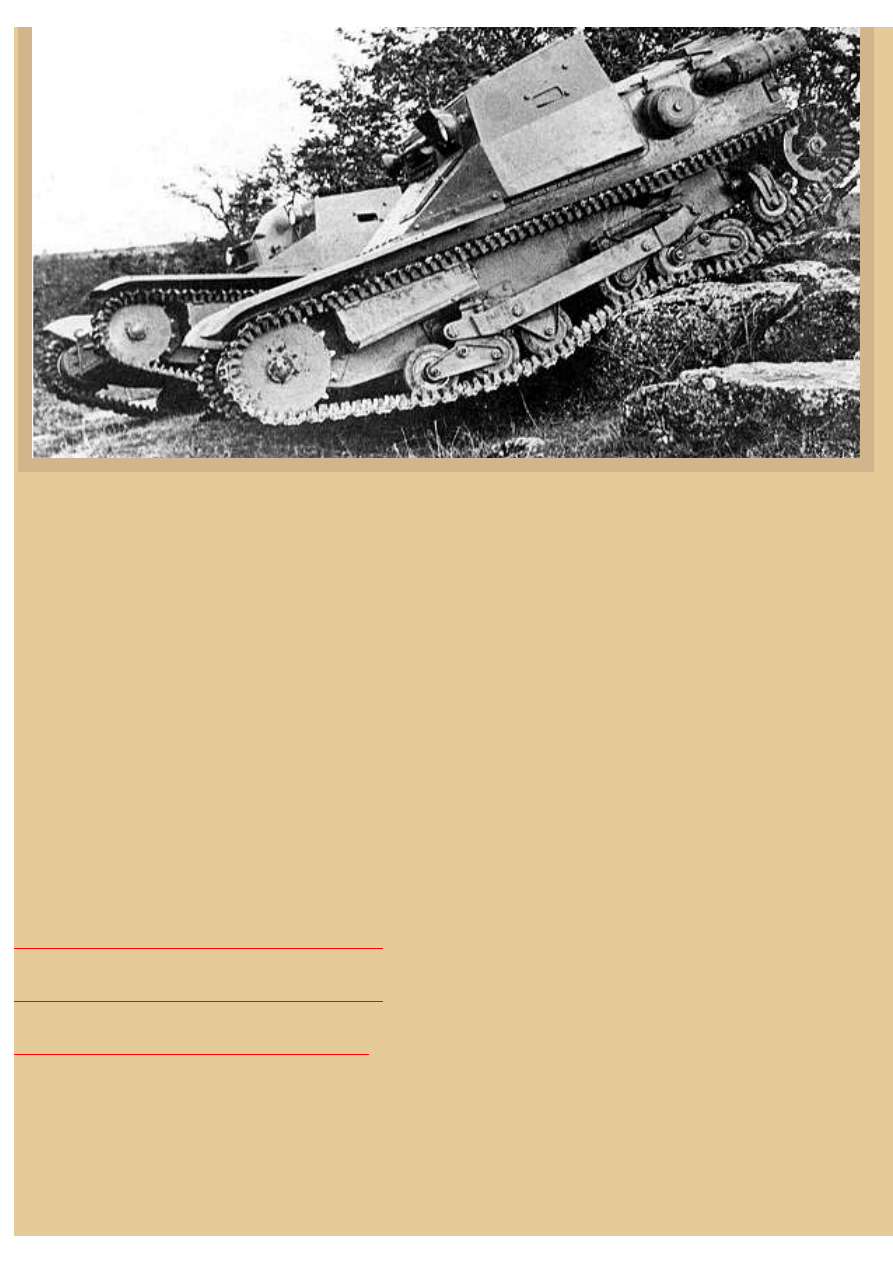
Picture 1:
This is the third part of a three-part series on the Italian CV-33/35 tankette. Most of the images presented here were sent in by
Pietro Podavini, from Italy, and I am very grateful for his generosity and interest in our L.3 project. This is a cross-section
drawing of the CV-35, indicating some of the major components that we have discussed so far. Notice how the driver's seat is
very low on the floor and that its back is attached directly to the gas tank behind. The drive shaft passes between the two
occupants. The radiator takes up most of the room at the rear of the engine compartment. The left steering lever is shown with
its attaching linkage leading forward to the epicyclic steering gears and the sketch even includes the arched ratchet at the base
of the lever, showing the palm release at the handle used to lock the lever via the ratchet in one position. Recall that the vehicle
was built by Ansaldo Fossati of Genova Sestri, but utilised FIAT mechanical parts, including the engine.
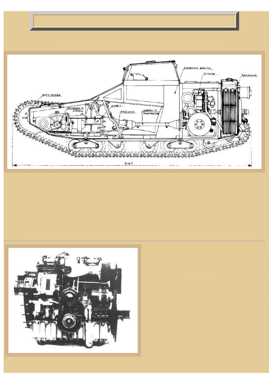
Picture 2:
This is the view of the front of the FIAT engine; the drive
shaft attachment is at the lower center. The engine was
mounted transverse in the tank and if you look closely you
will see the length of the oil pan on the bottom and the two
cylinder heads on top. The engine is said to have used side
valves and the total displacement was 2746cc. The FIAT
was water cooled and produced around 43hp during normal
driving at 2400rpm, with a redline rpm of 2900. The
pistons were made from a special aluminium alloy called
"Bonalite" and the carburettor was a Zenith TTHVI with
butterfly valves.
The gas tank behind the driver held 65 litres of gasoline;
the fuel system containing a fuel pump as well as a filter
mounted near the carburettor on top of the engine. A fuel
gage was mounted on top of the fuel tank and vehicle gas
mileage was approximately 1/2 litre of fuel per Km. The
water for the radiator totalled 23 litres and the radiator was
a circular one, almost completely surrounding the fan. Ignition was via a Marelli F.L.4 magneto, and a generator, driven by the
file:///H|/Modellismo/AFV%20Interiors/[armor]%20-%20AFV%20Interiors/afvinteriors.hobbyvista.com/cv35/cv35c.html (1 di 6)06/02/2007 19.46.36
file:///H|/Modellismo/AFV%20Interiors/[armor]%20-%20AFV%20Interiors/afvinteriors.hobbyvista.com/cv35/cv35c.html
engine, produced electricity for lights, both inside and outside the tank. The clutch was of the dry type and was operated by the
normal foot pedal method and a brake pedal was also included at the driver's feet.
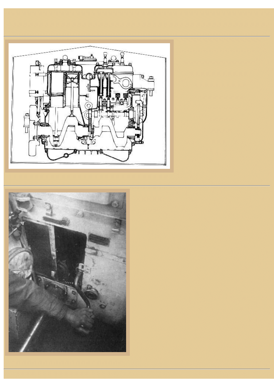
Picture 3:
Another view of the FIAT SPA CV3-005
engine, this time illustrated by a drawing of
the rear side. It shows particularly well the
general arrangement of the four in-line
cylinders. The crankshaft zigzags along the
bottom of the case, while the two pistons on
the left are shown with their rod bearings
attached to the crank. The right side of the
engine shows the arrangement of the valves
and their actuators, the lifters and cams
driven from below, not overhead. The
cylindrical shape you see at the upper left is
the oil filter.
Picture 4:
The engine could be started only by hand crank, either from inside
the compartment like this, or from the rear. We are looking at the
rear firewall, with the rectangular access hatch to the engine
compartment removed and the driver's left hand on the starting
crank. The unprotected drive shaft is under his forearm and one of
the vehicle identification plates is on the bulkhead above his hand.
The gas tank takes up most of the space to the far left in the
photograph and the commander/gunner's seat back has been
removed from the firewall, although the bracket is still mounted
(just under the vehicle ID plate).
file:///H|/Modellismo/AFV%20Interiors/[armor]%20-%20AFV%20Interiors/afvinteriors.hobbyvista.com/cv35/cv35c.html (2 di 6)06/02/2007 19.46.36
file:///H|/Modellismo/AFV%20Interiors/[armor]%20-%20AFV%20Interiors/afvinteriors.hobbyvista.com/cv35/cv35c.html
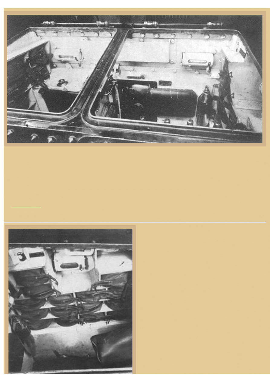
Picture 5:
When the two over-head hatches are opened you have a very good view of the rear bulkhead again. Notice that the engine
access hatch is open again, and the original gas tank is visible behind the driver's seat. The gunner's seat back is now attached
directly to the firewall on its bracket, and the twin grips of the two 8mm FIAT 35 MGs are visible just over the edge of the
open hatch. Also on the back wall are the two rotating vision flaps we have seen earlier, and on both sponsons you can see bins
for stowing MG ammo drums, in this case the drums are protected by canvas bag covers. At the right is the small fire
extinguisher mounted on the firewall. The two seating positions in the fighting compartment could be separated by a leather
sheet which was hung from the top spar and fixed at the bottom near the propeller shaft. The conical bolt heads holding
together the CV 35 are particularly well viewed at the lower left. This and a number of the other pictures in this part are from
the
Picture 6:
This view of the left sponson ammo bins shows the
arrangement for at least some of the magazines. The left side
view slit is visible here as well as the canvas covered receiver
of one of the machine guns to our right. The crew seats were
made from a wood frame with springs and the padding was
covered with brown leather. The seat backs were also made
from leather over horsehair padding, the driver's being fixed
to the front of the gasoline tank and the commander/gunner's
attached with the previously seen bracket onto the firewall. In
the CV-33, the floor was covered by four wooden floorboards,
covered by linoleum (very good for fires!) and in the CV-35
there were floorboards made of plywood that were painted
with waterproof paint. At the far left is the small fire
extinguisher bottle, sandwiched between the ammo bins on
the side and the engine access hatch on the rear wall.
file:///H|/Modellismo/AFV%20Interiors/[armor]%20-%20AFV%20Interiors/afvinteriors.hobbyvista.com/cv35/cv35c.html (3 di 6)06/02/2007 19.46.36
file:///H|/Modellismo/AFV%20Interiors/[armor]%20-%20AFV%20Interiors/afvinteriors.hobbyvista.com/cv35/cv35c.html
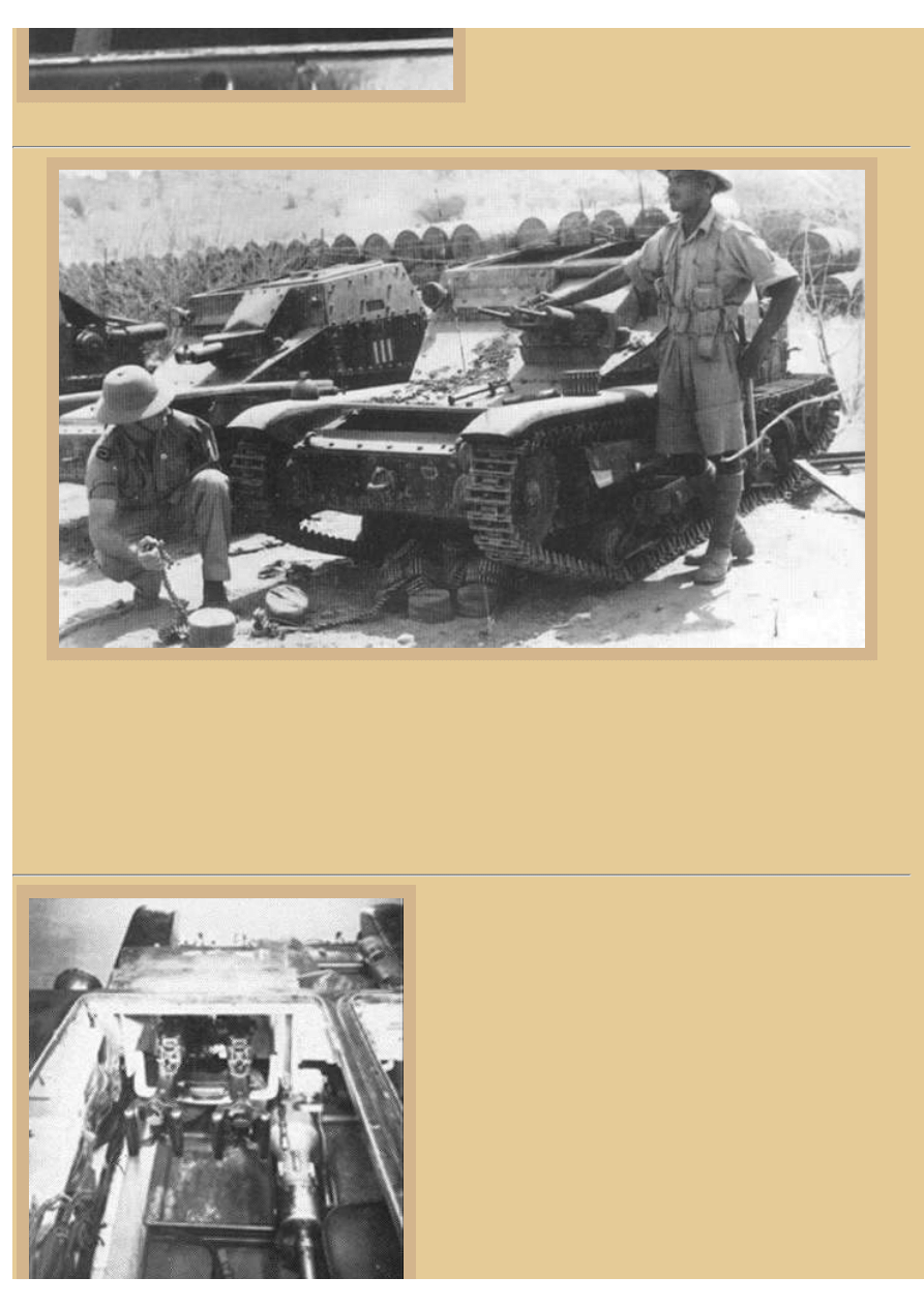
Picture 7:
This famous photo illustrates both styles of armament mounting, with the two different MG mantlets used, in this case with
8mm FIAT 35 MGs on the right and the MGs missing on the vehicle to the left. Many round ammo magazines (known in
Italian as 'bobina') litter the ground in front of one of the right tankette. An uncovered magazine is sitting up on the fender and
some unrolled belts are strewn around here and there. Each of these magazines contained a rolled strip of 80 cartridges and the
vehicles typically carried 29 drums of the 8mm ammo when they were fitted with the FIAT 35 MG. All three vehicles seem to
be on display at a fuel dump. This is an Imperial War Museum photograph, probably taken in Tobruk, and although the soldiers
are obviously Commonwealth, exactly which country they are from eludes me now. Do you have any suggestions?
Picture 8:
Back inside the tankette, this view shows the twin 8mm FIAT 35
MGs with their characteristic double handles, similar to those seen
on US Browning .50cal MGs. Again the drum magazine ammo bin is
visible to the left, up on the sponson, and the drive shaft and
transmission are seen off to the right.
A surprising number of countries used the L.3 at one time or another.
So far we have been able to find reference of use in Afghanistan,
Bolivia, Brazil, Bulgaria, China, Croatia, Hungary, Iraq, Spain,
England, Greece, and Yugoslavia. Some of these countries used
captured Italian vehicles and some were sold their tankettes from
Italy.
According to "I Carri Armati del Regio Esercito", ("The Armed
Tanks of the Royal Army" by Bruno Benvenuti, Roma Storia dei
Mezzi Corazzati, Edited by F.Fabbri), Germany used the L.3 in the
Balkans against Tito's partisans. The tankettes were manned by
file:///H|/Modellismo/AFV%20Interiors/[armor]%20-%20AFV%20Interiors/afvinteriors.hobbyvista.com/cv35/cv35c.html (4 di 6)06/02/2007 19.46.36
file:///H|/Modellismo/AFV%20Interiors/[armor]%20-%20AFV%20Interiors/afvinteriors.hobbyvista.com/cv35/cv35c.html
mainly German SS units, some sources indicating that they were the
7th SS-Freiwilligen-Gebirgs Division, Prinz Eugen. In brief, the
Italians, Germans, and Fascist Croats were all fighting the
communist guerrillas under Tito, who were called the "partisans".
The Serbian royalist forces, called "Chetniks" at that time, fought
both sides, depending on the particular circumstances at the time. Eventually, the partisans, with Allied help and Soviet troop
reinforcements, were able to drive the fascist troops either into hiding or out of the country. It is interesting to note that after the
war much of the ethnic and tribal hostility in the region was not so much resolved as politically frozen, only to ignite again, as
we have seen, in the 1990's.
Also, during the confused situation in Italy after September of 1943, some Italian tank units continued to fight along side
German forces; these L.3 tankettes had the Balkan Kreuze on their armor. There are published photos of German
Fallschirmajaegers on captured L.3s after the battle for Rome, in September of 1943.
Picture 9:
This time our view is of the rear of the twin Breda
MGs in their mount. The Breda MG magazine
contained only around 24 rounds, but there were
approximately 79 curved magazines stowed in the
vehicle. As you may recall, the Breda MGs caught
their spent casings in canvas bags fixes under the
weapons. The sighting ocular with its surrounding
eye cushion has been angled upward, but the rear of
both receivers and their characteristic handles below
them are clearly visible. Notice the hand wheel to the
far right that elevated and depressed the weapon
mount. The mount was traversed by simply swinging
the weapons from side to side. The very early L.3s
with the 6.5mm FIAT 14 MG had around 3800
rounds of ammo stowed inside 50 magazines, the
magazines housed in similar bins on both sponsons
over the tracks.
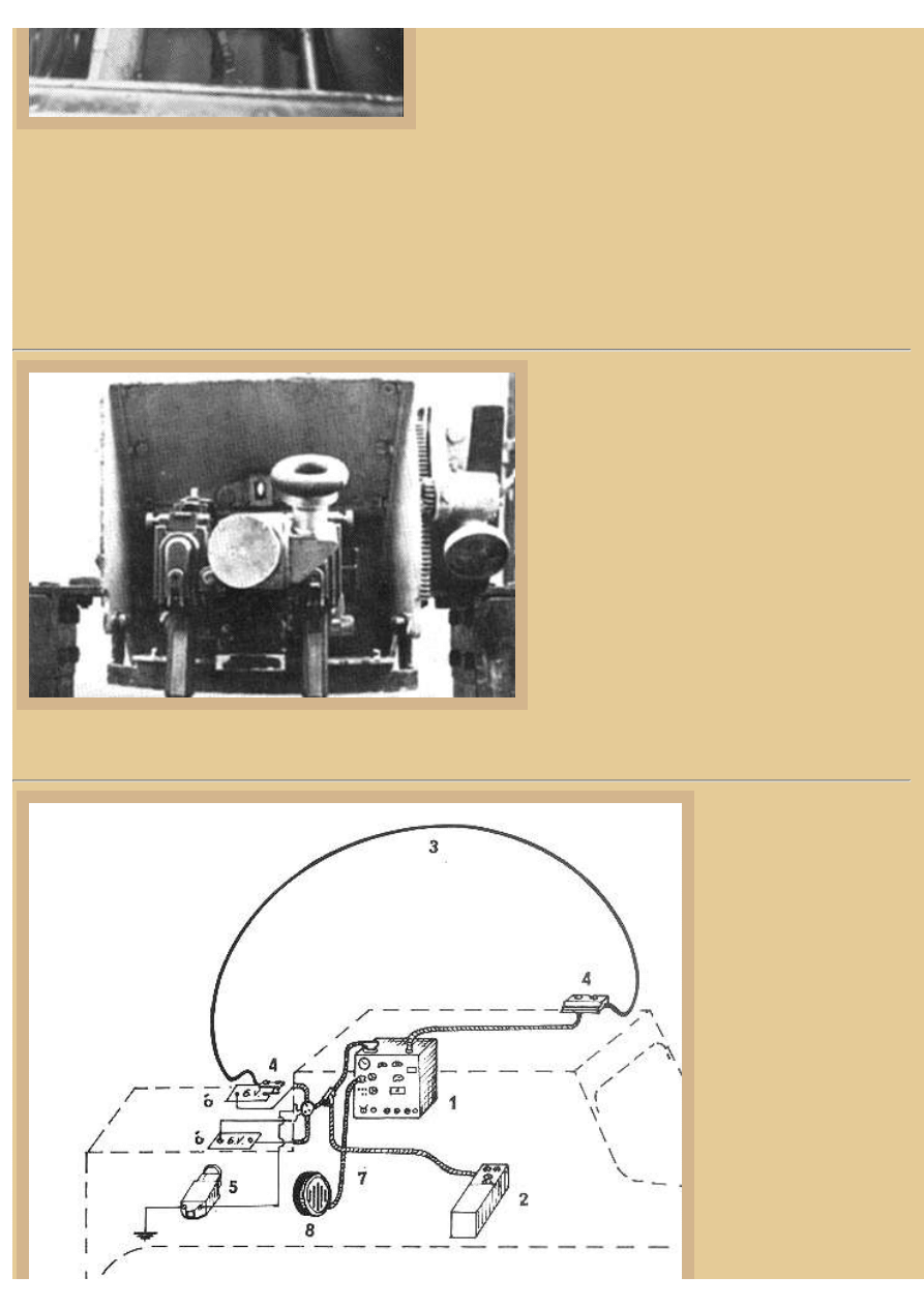
Picture 10:
There wasn't much room for
radios inside the L.3, and
they generally were not
carried. But when they were
installed in command
vehicles, they were normally
placed on the left sponson in
place of some of the MG
ammo. In some cases, radio
vehicles had no armament, or
only dummy guns, but
usually the MGs were kept
on board and only some of
the ammo reduced.
This sketch shows the
general arrangement of the R.
F.C.A. mod.37 radio setup.
Number 1 and 2 in the
drawing are the radio
transmitter/receiver, 3 is the
file:///H|/Modellismo/AFV%20Interiors/[armor]%20-%20AFV%20Interiors/afvinteriors.hobbyvista.com/cv35/cv35c.html (5 di 6)06/02/2007 19.46.36

file:///H|/Modellismo/AFV%20Interiors/[armor]%20-%20AFV%20Interiors/afvinteriors.hobbyvista.com/cv35/cv35c.html
distinctive curved antenna,
and the two number 4s are
the antenna base connections. Number 5 is the generator, 6 are the vehicle's batteries, 7 identifies the cables, and 8 is the
loudspeaker that was separate from the radio boxes. This curved antenna design was the one most often seen during the early
war years. It seems to me that most Italian tank radios were markedly influenced by German radio designs of the time and
many components were of German manufacture.
There were variations of the L.3 built for special purposes, the most numerous were the flame thrower versions that we
mentioned earlier. A limited number of tankettes were modified to mount a 2mm Solothurn anti-tank gun in place of the
machine guns, and some of these were encountered by the British in the Western Desert fighting in North Africa. Perhaps as
many as three-quarters of the Italian tank formations encountered by the British in the Western Desert in late 1940/early 1941
were composed of L.3s. And although the tankette continued to be used throughout the war, it was mainly only employed by
units of the RSI after September of 1943. The RSI (Repubblica Sociale Italiana) was the Italian Social Republic, a Fascist state
that was set up in Northern Italy under Mussolini after the Italo-Allied armistice of September 8, 1943.
My thanks go out again to both Celso Tondin Valente and Pietro Podavini for their invaluable assistance with these pages, not
only with the illustrations but with a good part of the copy. Without their assistance, these web pages exploring the diminutive
CV-33/35 would not have been possible. Should you have additional information that you would like to share, we would all be
happy to hear from you.
TO ITALIAN CV 33/35 TANKETTE PART 1
TO ITALIAN CV 33/35 TANKETTE PART 2
BACK TO AFV INTERIORS HOME PAGE
(c) 2001, 2003 AFV INTERIORS Web Magazine
file:///H|/Modellismo/AFV%20Interiors/[armor]%20-%20AFV%20Interiors/afvinteriors.hobbyvista.com/cv35/cv35c.html (6 di 6)06/02/2007 19.46.36
Document Outline
Wyszukiwarka
Podobne podstrony:
12,33,35,37
33 35
33 35 (3)
33 35
33 35 (4)
33 35 (2)
33 35
33 35
33 35 (5)
33 35
AFV Interiors Water Buffalo
Afv Interiors Isu 152
AFV Interiors German AFV Radio Equipment In WWII
AFV Interiors M1A2 Abrams
AFV Interiors British Medium Tank Mk I & Mk II
AFV Interiors Czech Light Tank, LT vz 38, Pz Kpfw 38(t)
AFV Interiors Leopard 2
więcej podobnych podstron