1 - 13
CCNP: Optimizing Converged Networks v5.0 - Lab 6-1a
Copyright
© 2007, Cisco Systems, Inc
Lab 6.1a Configuring a WLAN Controller
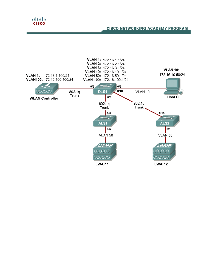
Topology Diagram
Scenario
In the next two labs, you will configure a wireless solution involving a WLAN
controller, two lightweight wireless access points, and a switched wired
network. You will configure a WLAN controller to broadcast SSIDs from the
lightweight wireless access points. If you have a wireless client nearby, connect
to the WLANs and access devices from the inside of your pod to verify your
configuration of the controller and access points.
Note: It is required that you upgrade the WLC firmware image to 4.0.206.0 or
higher in order to accomplish this lab.
Step 1
Erase the startup-config file and delete the vlan.dat file from each switch. On
the WLAN controller, use the clear controller command followed by the reset
system command to reset them.

Step 2
Explanation of VLANs:
VLAN 1 – This VLAN is the management VLAN for the WLC
VLAN 2 and VLAN 3 – These VLANs are for hosts in the WLANs
VLAN 10 – The host is in this VLAN
VLAN 50 – The APs are in this VLAN
VLAN 100 – The AP-manager interface of the WLC is in this VLAN
Set up DLS1 as a VTP server, and ALS1 and ALS2 as clients. Put them in VTP
domain CISCO. Set up the switch-to-switch links shown in the diagram as
802.1q trunks. Add VLANs 2, 3, 10, 50, and 100 to DLS1.
DLS1(config)# vtp mode server
DLS1(config)# vtp domain CISCO
DLS1(config)# vlan 2,3,10,50,100
DLS1(config-vlan)# interface fastethernet0/8
DLS1(config-if)# switchport trunk encapsulation dot1q
DLS1(config-if)# switchport mode trunk
DLS1(config-if)# interface fastethernet0/10
DLS1(config-if)# switchport trunk encapsulation dot1q
DLS1(config-if)# switchport mode trunk
ALS1(config)# vtp mode client
ALS1(config)# vtp domain CISCO
ALS1(config)# interface fastethernet0/8
ALS1(config-if)# switchport mode trunk
ALS2(config)# vtp mode client
ALS2(config)# vtp domain CISCO
ALS2(config)# interface fastethernet0/10
ALS2(config-if)# switchport mode trunk
Verify that VTP traffic has passed between the switch by comparing the non-
zero VTP configuration revision between switches with the show vtp status
command.
DLS1# show vtp status
VTP Version : 2
Configuration Revision : 1
Maximum VLANs supported locally : 1005
Number of existing VLANs : 10
VTP Operating Mode : Server
VTP Domain Name : CISCO
VTP Pruning Mode : Disabled
VTP V2 Mode : Disabled
VTP Traps Generation : Disabled
MD5 digest : 0x6A 0x6B 0xCA 0x3C 0xF0 0x45 0x87 0xAC
Configuration last modified by 0.0.0.0 at 3-1-93 00:02:01
Local updater ID is 0.0.0.0 (no valid interface found)
ALS1# show vtp status
VTP Version : 2
Configuration Revision : 1
Maximum VLANs supported locally : 255
Number of existing VLANs : 10
VTP Operating Mode : Client
2 - 13
CCNP: Optimizing Converged Networks v5.0 - Lab 6-1a
Copyright
© 2007, Cisco Systems, Inc

VTP Domain Name : CISCO
VTP Pruning Mode : Disabled
VTP V2 Mode : Disabled
VTP Traps Generation : Disabled
MD5 digest : 0x6A 0x6B 0xCA 0x3C 0xF0 0x45 0x87 0xAC
Configuration last modified by 0.0.0.0 at 3-1-93 00:02:01
ALS2# show vtp status
VTP Version : 2
Configuration Revision : 1
Maximum VLANs supported locally : 255
Number of existing VLANs : 10
VTP Operating Mode : Client
VTP Domain Name : CISCO
VTP Pruning Mode : Disabled
VTP V2 Mode : Disabled
VTP Traps Generation : Disabled
MD5 digest : 0x6A 0x6B 0xCA 0x3C 0xF0 0x45 0x87 0xAC
Configuration last modified by 0.0.0.0 at 3-1-93 00:02:01
Step 3
Configure all the switched virtual interfaces (SVIs) shown in the diagram for
DLS1.
DLS1(config)# interface vlan 1
DLS1(config-if)# ip address 172.16.1.1 255.255.255.0
DLS1(config-if)# interface vlan 2
DLS1(config-if)# ip address 172.16.2.1 255.255.255.0
DLS1(config-if)# interface vlan 3
DLS1(config-if)# ip address 172.16.3.1 255.255.255.0
DLS1(config-if)# interface vlan 10
DLS1(config-if)# ip address 172.16.10.1 255.255.255.0
DLS1(config-if)# interface vlan 50
DLS1(config-if)# ip address 172.16.50.1 255.255.255.0
DLS1(config-if)# interface vlan 100
DLS1(config-if)# ip address 172.16.100.1 255.255.255.0
Step 4
DHCP gives out dynamic IP addresses on a subnet to network devices or hosts
rather than statically setting the addresses. This is useful when dealing with
lightweight access points, which usually do not have an initial configuration. The
WLAN controller that the lightweight wireless access point associates with
defines the configuration. A lightweight access point can dynamically receive an
IP address and then communicate over IP with the WLAN controller. In this
scenario, you will also use it to assign IP addresses to hosts that connect to the
WLANs.
First, set up DLS1 to exclude the first 150 addresses from each subnet from
DHCP to avoid conflicts with static IP addresses by using the global
configuration command ip dhcp excluded-address low-address [high-
address].
DLS1(config)# ip dhcp excluded-address 172.16.1.1 172.16.1.150
DLS1(config)# ip dhcp excluded-address 172.16.2.1 172.16.2.150
DLS1(config)# ip dhcp excluded-address 172.16.3.1 172.16.3.150
3 - 13
CCNP: Optimizing Converged Networks v5.0 - Lab 6-1a
Copyright
© 2007, Cisco Systems, Inc

DLS1(config)# ip dhcp excluded-address 172.16.10.1 172.16.10.150
DLS1(config)# ip dhcp excluded-address 172.16.50.1 172.16.50.150
DLS1(config)# ip dhcp excluded-address 172.16.100.1 172.16.100.150
To advertise on different subnets, create DHCP pools with the ip dhcp pool
name command. After a pool is configured for a certain subnet, the IOS DHCP
server processes requests on that subnet, because it is enabled by default.
From the DHCP pool prompt, set the network and mask to use with the
network address /mask command. Set a default gateway with the default-
router address command.
VLAN 50 also uses the option command, which allows you to specify a DHCP
option. In this case, option 43 is specified (a vendor-specific option), which
gives the lightweight wireless access points the IP address of the WLAN
controller AP Manager interface. It is specified in a hexadecimal TLV (type,
length, value) format. F1 is the hardcoded type of option, 04 represents the
length of the value (an IP address is 4 octets), and AC106464 is the
hexadecimal representation of 172.16.100.100, which is going to be the AP
manager address of the WLAN controller. DHCP option 60 specifies the
identifier that access points will use in DHCP. This lab was written using Cisco
Aironet 1240 series access points. If you are using a different access point
series, consult
http://www.cisco.com/univercd/cc/td/doc/product/wireless/aero1500/1500hig5/1
500_axg.htm
.
DLS1(config)# ip dhcp pool pool1
DLS1(dhcp-config)# network 172.16.1.0 /24
DLS1(dhcp-config)# default-router 172.16.1.1
DLS1(dhcp-config)# ip dhcp pool pool2
DLS1(dhcp-config)# network 172.16.2.0 /24
DLS1(dhcp-config)# default-router 172.16.2.1
DLS1(dhcp-config)# ip dhcp pool pool3
DLS1(dhcp-config)# network 172.16.3.0 /24
DLS1(dhcp-config)# default-router 172.16.3.1
DLS1(dhcp-config)# ip dhcp pool pool10
DLS1(dhcp-config)# network 172.16.10.0 /24
DLS1(dhcp-config)# default-router 172.16.10.1
DLS1(dhcp-config)# ip dhcp pool pool50
DLS1(dhcp-config)# network 172.16.50.0 /24
DLS1(dhcp-config)# default-router 172.16.50.1
DLS1(dhcp-config)# option 43 hex f104ac106464
DLS1(dhcp-config)# option 60 ascii "Cisco AP c1240"
DLS1(dhcp-config)# ip dhcp pool pool100
DLS1(dhcp-config)# network 172.16.100.0 /24
DLS1(dhcp-config)# default-router 172.16.100.1
Step 5
On all three switches, configure each access point’s switchport with the
spanning-tree portfast command so that each access point receives an IP
address from DHCP immediately, thereby avoiding spanning-tree delays. Use
VLAN 100 as the AP Manager interface for the WLAN controller. All control and
data traffic between the controller and the lightweight wireless access points
4 - 13
CCNP: Optimizing Converged Networks v5.0 - Lab 6-1a
Copyright
© 2007, Cisco Systems, Inc

passes over this VLAN to this interface. Configure the ports going to the
lightweight wireless access points in VLAN 50. DLS1 will route the traffic
between the VLANs. Configure the interface on DLS1 that connects to the
WLAN controller as an 802.1q trunk.
DLS1(config)# interface fastethernet0/5
DLS1(config-if)# switchport trunk encapsulation dot1q
DLS1(config-if)# switchport mode trunk
ALS1(config)# interface fastethernet0/5
ALS1(config-if)# switchport mode access
ALS1(config-if)# switchport access vlan 50
ALS1(config-if)# spanning-tree portfast
ALS2(config)# interface fastethernet0/5
ALS2(config-if)# switchport mode access
ALS2(config-if)# switchport access vlan 50
ALS2(config-if)# spanning-tree portfast
Step 6
You have a PC running Microsoft Windows attached to DLS1. First, configure
the switchport facing the host to be in VLAN 10.
DLS1(config)# interface fastethernet0/6
DLS1(config-if)# switchport mode access
DLS1(config-if)# switchport access vlan 10
DLS1(config-if)# spanning-tree portfast
Next, configure the host with an IP address in VLAN 10, which will later be used
to access the HTTP web interface of the WLAN controller.
In the Control Panel, select Network Connections.
5 - 13
CCNP: Optimizing Converged Networks v5.0 - Lab 6-1a
Copyright
© 2007, Cisco Systems, Inc
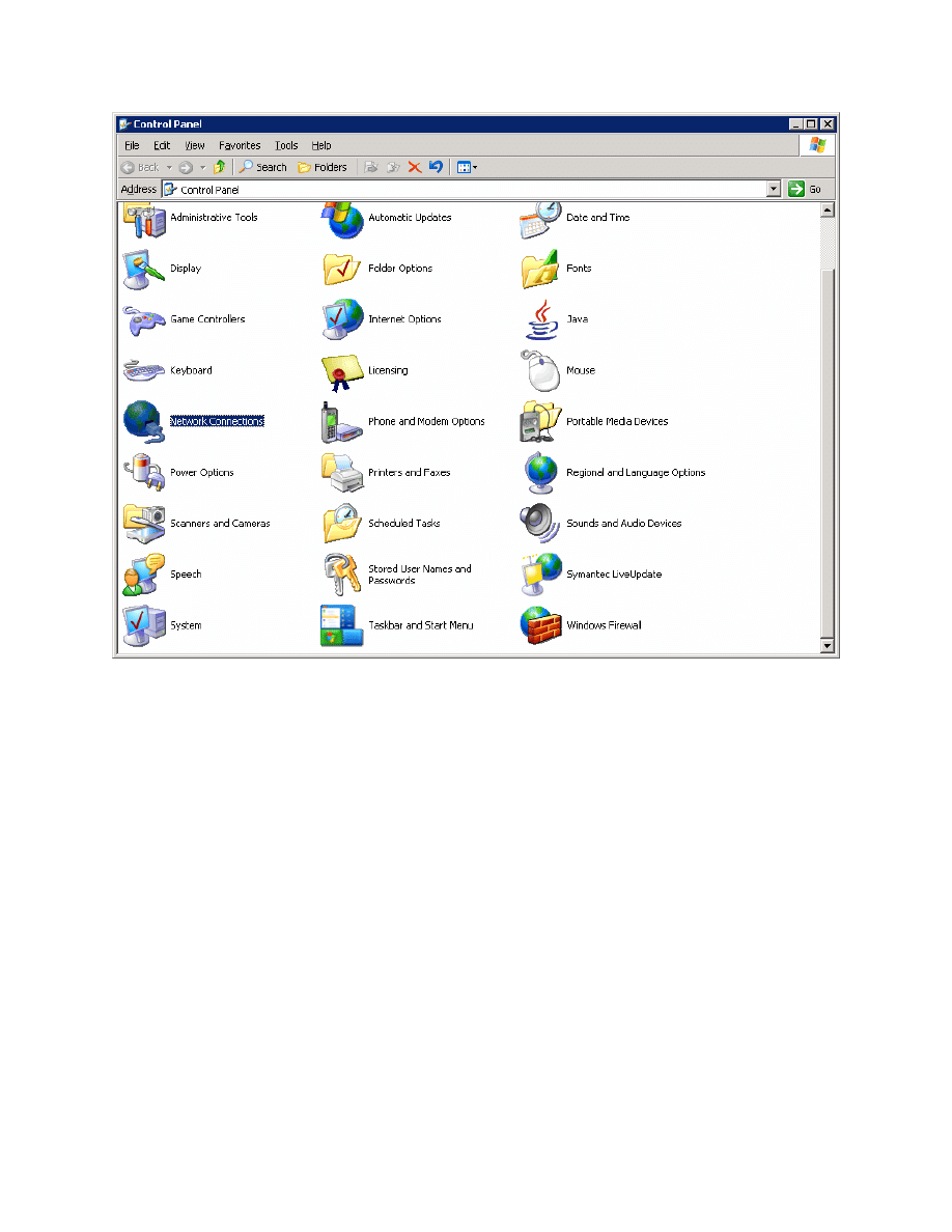
Figure 5-1: Microsoft Windows Control Panel
Right-click on the LAN interface that connects to DLS1, and select Properties.
Select Internet Protocol (TCP/IP) and then click the Properties button.
6 - 13
CCNP: Optimizing Converged Networks v5.0 - Lab 6-1a
Copyright
© 2007, Cisco Systems, Inc
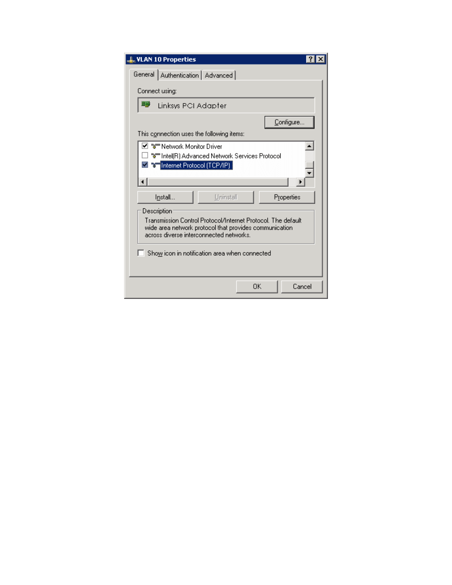
Figure 5-2: Modify the Properties for Interface on VLAN 10
Finally, configure the IP address shown in the diagram on the interface.
7 - 13
CCNP: Optimizing Converged Networks v5.0 - Lab 6-1a
Copyright
© 2007, Cisco Systems, Inc
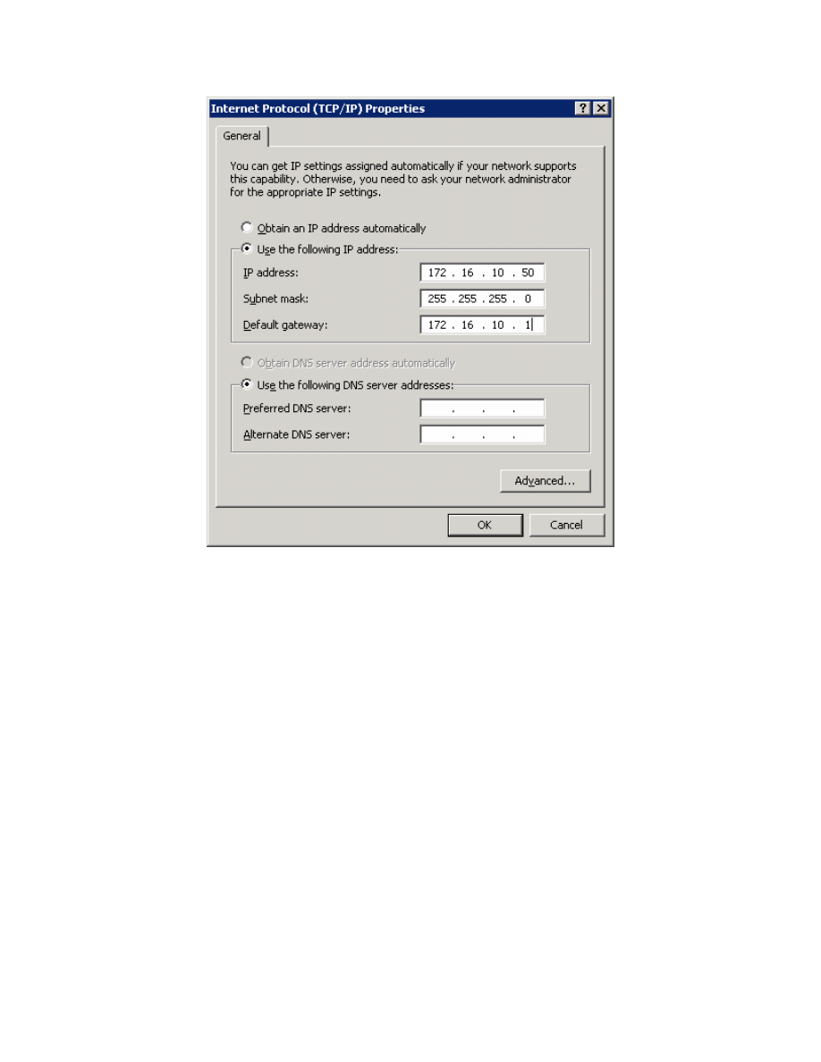
Figure 5-3: Configure IP Address, Subnet, and Gateway
Click OK to apply the TCP/IP settings, and then again to exit the configuration
dialog box. From the Start Menu, click Run. Issue the cmd command and press
the Return key. At the Windows command-line prompt, ping DLS1’s VLAN 10
interface. You should receive responses. If you do not, troubleshoot, verifying
the VLAN of the switchport and the IP address and subnet mask on each of the
devices on VLAN 10.
C:\Documents and Settings\Administrator> ping 172.16.10.1
Pinging 172.16.10.1 with 32 bytes of data:
Reply from 172.16.10.1: bytes=32 time=1ms TTL=255
Reply from 172.16.10.1: bytes=32 time<1ms TTL=255
Reply from 172.16.10.1: bytes=32 time<1ms TTL=255
Reply from 172.16.10.1: bytes=32 time<1ms TTL=255
Ping statistics for 172.16.10.1:
Packets: Sent = 4, Received = 4, Lost = 0 (0% loss),
Approximate round trip times in milli-seconds:
Minimum = 0ms, Maximum = 1ms, Average = 0ms
8 - 13
CCNP: Optimizing Converged Networks v5.0 - Lab 6-1a
Copyright
© 2007, Cisco Systems, Inc

Step 7
Enable IP routing on DLS1. This lets DLS1 route between all subnets shown in
the diagram. DLS1 can effectively route between all the VLANs configured
because it has an SVI in each subnet. Each IP subnet is shown in the output of
the show ip route command issued on DLS1.
DLS1(config)# ip routing
DLS1# show ip route
Codes: C - connected, S - static, R - RIP, M - mobile, B - BGP
D - EIGRP, EX - EIGRP external, O - OSPF, IA - OSPF inter area
N1 - OSPF NSSA external type 1, N2 - OSPF NSSA external type 2
E1 - OSPF external type 1, E2 - OSPF external type 2, E - EGP
i - IS-IS, su - IS-IS summary, L1 - IS-IS level-1, L2 - IS-IS level-2
ia - IS-IS inter area, * - candidate default, U - per-user static route
o - ODR, P - periodic downloaded static route
Gateway of last resort is not set
172.16.0.0/24 is subnetted, 7 subnets
C 172.16.1.0 is directly connected, Vlan1
C 172.16.2.0 is directly connected, Vlan2
C 172.16.3.0 is directly connected, Vlan3
C 172.16.10.0 is directly connected, Vlan10
C 172.16.50.0 is directly connected, Vlan50
C 172.16.100.0 is directly connected, Vlan100
Step 8
When you first restart the WLAN controller, a configuration wizard prompts you
to enter basic configuration attributes. You will know that you have entered the
wizard interface when you see “Welcome to the Cisco Wizard Configuration
Tool.” Pressing the Return key allows the default configuration options to be
used. The default option will be in square brackets in the wizard prompts. If
there is more than once choice in square brackets, it will be the option in capital
letters.
The first prompt asks for a hostname. Use the default. Use “cisco” as both the
username and password.
Welcome to the Cisco Wizard Configuration Tool
Use the '-' character to backup
System Name [Cisco_49:43:c0]:
Enter Administrative User Name (24 characters max): cisco
Enter Administrative Password (24 characters max): <cisco>
Enter the management interface information. The management interface
communicates with the management workstation in VLAN 1. The interface
number is 1, because this is the port trunked from the controller to the switch.
The VLAN number is 0 for untagged. It is untagged because VLAN 1 is the
native 802.1q VLAN, and is therefore sent untagged through 802.1q trunks.
Management Interface IP Address: 172.16.1.100
Management Interface Netmask: 255.255.255.0
9 - 13
CCNP: Optimizing Converged Networks v5.0 - Lab 6-1a
Copyright
© 2007, Cisco Systems, Inc

Management Interface Default Router: 172.16.1.1
Management Interface VLAN Identifier (0 = untagged): 0
Management Interface Port Num [1 to 4]: 1
Management Interface DHCP Server IP Address: 172.16.1.1
Configure an interface to communicate with the lightweight access points. This
will be in VLAN 100 and is tagged as such on the trunk.
AP Manager Interface IP Address: 172.16.100.100
AP Manager Interface Netmask: 255.255.255.0
AP Manager Interface Default Router: 172.16.100.1
AP Manager Interface VLAN Identifier (0 = untagged): 100
AP Manager Interface Port Num [1 to 4]: 1
AP Manager Interface DHCP Server (172.16.1.1): 172.16.100.1
Configure the virtual gateway IP address as 1.1.1.1 (this is acceptable because
you are not using this for routing). The virtual gateway IP address is typically a
fictitious, unassigned IP address, such as the address we are using here, to be
used by Layer 3 Security and Mobility managers.
Virtual Gateway IP Address: 1.1.1.1
Configure the mobility group and network name as “ccnppod.” Allow static IP
addresses by hitting enter, but do not configure a RADIUS server now.
Mobility/RF Group Name: ccnppod
Network Name (SSID): ccnppod
Allow Static IP Addresses [YES][no]:
Configure a RADIUS Server now? [YES][no]: no
Warning! The default WLAN security policy requires a RADIUS server.
Please see documentation for more details.
Use the defaults for the rest of the settings. (Hit enter on each prompt).
Enter Country Code (enter 'help' for a list of countries) [US]:
Enable 802.11b Network [YES][no]:
Enable 802.11a Network [YES][no]:
Enable 802.11g Network [YES][no]:
Enable Auto-RF [YES][no]:
Configuration saved!
Resetting system with new configuration...
Step 9
When the WLAN controller has finished restarting, log in with the username
“cisco” and password “cisco.”
User: cisco
Password: <cisco>
10 - 13
CCNP: Optimizing Converged Networks v5.0 - Lab 6-1a
Copyright
© 2007, Cisco Systems, Inc

Change the controller prompt to WLAN_CONTROLLER with the config prompt
name command. Notice that the prompt changes.
(Cisco Controller) > config prompt WLAN_CONTROLLER
(WLAN_CONTROLLER) >
Enable Telnet and HTTP access to the WLAN controller. HTTPS access is
enabled by default, but unsecured HTTP is not.
(WLAN_CONTROLLER) > config network telnet enable
(WLAN_CONTROLLER) > config network webmode enable
Save your configuration with the save config command, which is analogous to
the Cisco IOS copy run start command.
(WLAN_CONTROLLER) > save config
Are you sure you want to save? (y/n) y
Configuration Saved!
To verify the configuration, you can issue the show interface summary, show
wlan summary, and show run-config commands on the WLAN controller.
How is the WLAN controller’s show run-config command different than the
Cisco IOS show running-config command?
Final Configurations
DLS1# show run
hostname DLS1
!
ip routing
ip dhcp excluded-address 172.16.1.1 172.16.1.150
ip dhcp excluded-address 172.16.2.1 172.16.2.150
ip dhcp excluded-address 172.16.3.1 172.16.3.150
ip dhcp excluded-address 172.16.10.1 172.16.10.150
ip dhcp excluded-address 172.16.50.1 172.16.50.150
ip dhcp excluded-address 172.16.100.1 172.16.100.150
!
ip dhcp pool pool2
network 172.16.2.0 255.255.255.0
default-router 172.16.2.1
!
ip dhcp pool pool3
network 172.16.3.0 255.255.255.0
default-router 172.16.3.1
!
ip dhcp pool pool10
network 172.16.10.0 255.255.255.0
default-router
172.16.10.1
!
11 - 13
CCNP: Optimizing Converged Networks v5.0 - Lab 6-1a
Copyright
© 2007, Cisco Systems, Inc

ip dhcp pool pool50
network 172.16.50.0 255.255.255.0
default-router 172.16.50.1
option 43 hex f104ac106464
option 60 ascii "Cisco AP c1240"
!
ip dhcp pool pool100
network 172.16.100.0 255.255.255.0
default-router 172.16.100.1
!
ip dhcp pool pool1
network 172.16.1.0 255.255.255.0
default-router 172.16.1.1
!
interface FastEthernet0/5
switchport trunk encapsulation dot1q
switchport mode trunk
!
interface FastEthernet0/6
switchport mode access
switchport access vlan 10
spanning-tree portfast
!
interface FastEthernet0/7
switchport trunk encapsulation dot1q
switchport mode trunk
!
interface FastEthernet0/9
switchport trunk encapsulation dot1q
switchport mode trunk
!
interface Vlan1
ip address 172.16.1.1 255.255.255.0
no shutdown
!
interface Vlan2
ip address 172.16.2.1 255.255.255.0
no shutdown
!
interface Vlan3
ip address 172.16.3.1 255.255.255.0
no shutdown
!
interface Vlan10
ip address 172.16.10.1 255.255.255.0
no shutdown
!
interface Vlan50
ip address 172.16.50.1 255.255.255.0
no shutdown
!
interface Vlan100
ip address 172.16.100.1 255.255.255.0
no shutdown
end
ALS1# show run
hostname ALS1
!
interface FastEthernet0/5
switchport access vlan 50
switchport mode access
spanning-tree portfast
12 - 13
CCNP: Optimizing Converged Networks v5.0 - Lab 6-1a
Copyright
© 2007, Cisco Systems, Inc

!
interface FastEthernet0/7
switchport mode trunk
end
ALS2# show run
hostname ALS2
!
interface FastEthernet0/5
switchport access vlan 50
switchport mode access
spanning-tree portfast
!
interface FastEthernet0/9
switchport mode trunk
!
end
13 - 13
CCNP: Optimizing Converged Networks v5.0 - Lab 6-1a
Copyright
© 2007, Cisco Systems, Inc
Wyszukiwarka
Podobne podstrony:
CCNP4 lab 6 1b en
CCNP4 lab 6 2b en
CCNP4 lab 6 2a en
CCNP4 lab 6 4 en
CCNP4 lab 4 9 en
CCNP4 lab 3 1 en
CCNP4 lab 4 7 en
CCNP4 lab 4 8 en
CCNP4 lab 3 2 en
CCNP4 lab 3 3 en
CCNP4 lab 4 2 en
CCNP4 lab 4 6 en
CCNP4 lab 5 1 en
CCNP4 lab 2 1 en
CCNP4 lab 4 4 en
CCNP4 lab 4 3 en
CCNP4 lab 6 3 en
CCNP4 lab 4 5 en
CCNP4 lab 4 1 en
więcej podobnych podstron