PLEASE READ THIS INSTRUCTION MANUAL BEFORE INSTALLING,
OPERATING OR SERVICING THE PUMP
Your Reference
Iron Pump Reference
Purpose
:
Pump Type :
Order No.
:
Order No.
:
Art No.
:
Pump No.
:
Project
:
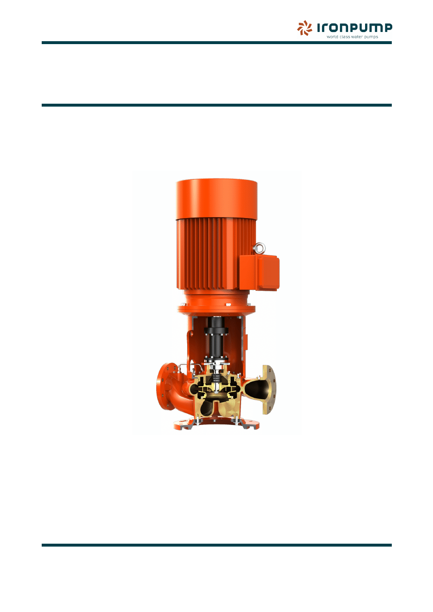
IRON PUMP
Instruction Manual
REVISION: 4
I
nstructions for Installation, Operation, Maintenance and Repair of
Centrifugal pumps Type DHBS and DHBF -/160, 200, 250,315, 400
2
Technical Data
TECHNICAL DATA
Pump
Flow, Q
:
Head (Diff. pressure), H :
Inlet pressure
:
Discharge pressure :
Suction lift
:
Power Duty Point, P :
Power max.
:
Media
:
Media temp.
:
Seal type
:
Impeller no.
:
Coupling type
:
Weight
:
Direction of rotation, Rot.:
Materials
Pump casing
:
Impeller
:
Casing wear ring
:
Shaft
:
Seal
:
Motor
Type
:
Output
:
RPM, n
:
Voltage
:
Weight
:
NB!
:
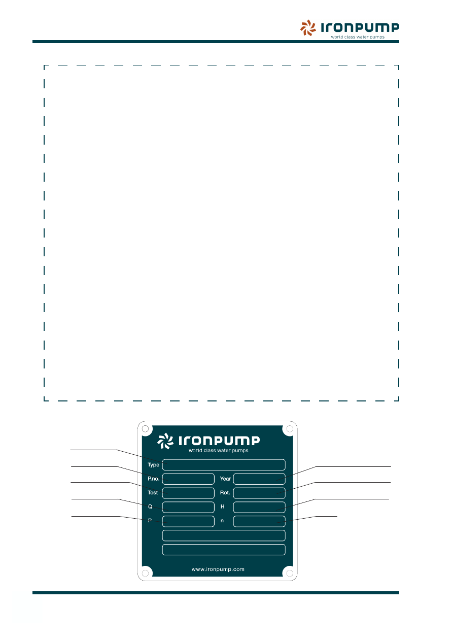
Type plate
Pump Type
Pump No.
Test pressure, Bar
Flow
Power
Duty Point
Year of manufacture
Direction of rotation
Head (Diff. pressure)
RPM

3
1
Contents
1. CoNTENTs
Chapter Section
Page
1.
Contents
3
2.
General
5
2.1
Introduction
5
2.2
Identification
5
2.3
Directions & Warning signs
5
2.4
Warning symbols
5
2.5
General safety
5
3.
Installation
7
3.1
Condition on delivery
7
3.2
Inspection on delivery
7
3.3
Storage instructions
7
3.4
Lifting instruction
7
3.5
Foundation
8
3.6
Environment conditions
8
3.7
Piping
8
3.8
Piping connections
8
3.9
Electrical installation
8
3.10
Recommended accessories
8
4.
Operation
9
4.1
Start-up procedures
9
4.2
Starting the pump
9
4.3
Stand-by
9
4.4
Pump vibrations
9
4.5
Lubrication
9
4.6
Frost protection
9
5.
Maintenance
11
5.1
Inspections
10
5.2
Assembly and Disassembly
10
5.3
Coupling
12
5.4
Fitting instructions for Mechanical seals
13
5.5
Centrifugal pump wear ring Clearances
14
6.
Spare Parts
15
6.1
Repairs
15
6.2
Returning parts
15
6.3
Decommissioning
15
6.4
Table of Materials
15
6.5
Spare parts drawing for DHBF/DHBS
16
1. CoNTENTs
4
1
Contents
1. CoNTENTs
Chapter Section
Page
7.
Data
17
7.1
Type DHBF/DHBS - Dimensional drawing
17
7.2
Troubleshooting
18
8.
Priming systems
20
8.1
Priming of centrifugal pumps
20
8.2
EA automatic ejector system
21
8.3
VATEC automatic aspirator
22
8.4
PA automatic priming system
23
8.5
Danfoss pressure controller for Priming systems
24
8.6
Wiring diagrams for Priming systems
25
8.7
Spare Parts drawing for P-pump with gear - 1450 RPM
26
8.8
Spare Parts drawing for P-pump – 1750 RPM
27
9.
Motor
28
9.1
General information
28
9.2
Inspection
28
9.3
Insulation resistance check
28
9.4
Handling
28
9.5
Installation
28
9.6
Repair and Maintenance
30
9.7
Spare Parts and Repair
31
9.8
Troubleshooting
32
5
General
2
2. GENErAL
2.1
Introduction
This instruction manual contains relevant
information on installing, operating and
maintaining the pump.
The pump is configured for the specific
customer requirements. The specific pump type
is described in the technical data section.
The personnel in charge of installing,
operating and maintaining the pump must be
properly qualified and trained to carry out the
operations described in this manual. IRON
Pump recommends that you read this manual
before you install and operate the pump as this
will minimize any risk of incorrect handling.
IRON Pump A/S cannot be held responsible
for unauthorized use of the pump.
IRON Pump A/S does not provide any guarantee
if working conditions are inappropriate. If the
working conditions differ from those given in
the technical data sheet, please contact IRON
Pump before putting the pump into operation.
2.2
Identification
Details of the pump identification (type, number
and order No.) are on the front page. The Pump
No. can also be found on the suction flange
and on the Type plate on the pump.
2.3 Directions & Warning signs
Comply with all instructions located on the
pump or motor, such as direction of rotation,
arrows, instruction signs, directions or warning
signs and remember to keep this information
in readable condition.
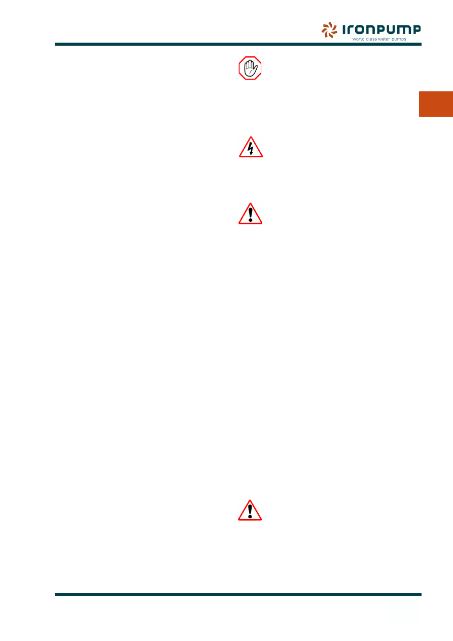
2.4
Warning symbols
Important machine and safety-related
instructions in this manual are illustrated with
symbols. It is essential that these instructions
are followed to avoid accidents and damages
to machines and/or personnel.
STOP!
This symbol is for all safety instructions which
must be followed to avoid accidental injuries
and hazards to life. Observe these safety
instructions carefully and proceed with great
care.
ELECTRIC POWER!
This symbol signals possible danger due
to presence of current electric power. Only
proceed if the operator is experienced with the
pump and procedures.
CAUTION!
This symbol is used for instructions of particular
importance and signals a risk of damage to
the pump or its components. Proceed only if
the parts or the pump have been assembled
according to the instructions.
2.5
General safety
The following safety instructions apply for both
pumps and motors supplied by IRON Pump
A/S.
Observe:
The safety regulations
•
Accident prevention regulations
•
Country specific safety regulations
•
Guide lines and acknowledged technical
•
rules cited in this operating manual.
Non-compliance with safety regulations will
result in danger to personnel and damage to
the unit, e.g:
Danger to personnel through contact with
•
voltage exceeding 42V.
Failure to observe prescribed methods of
•
transportation, assembly, maintenance
and repair of pump or motor.
When working on the
unit, observe all valid
accident prevention regulations
and generally acknowledged
technical rules!
2. GENErAL
6
2
General
2. GENErAL
2.5.1
Electrical hazards
Do not carry out any installation or maintenance
on the pump or motor while it is operating or
before it has been disconnected. Pumps with
motors must have appropriate connections.
Amp ratings are given in the pump Technical
data sheet and the power supply must be
adequate.
2.5.2
Temperature hazards
Before any maintenance is carried out, be
sure to empty the pump of liquid. If the pump
has been pumping hot liquid, the pump should
be cooled to the surrounding temperature.
As a precaution, the hot parts of the machine
should always be covered to avoid accidental
contact.
2.5.3
Chemical hazards
The pump should always be cleaned before
carrying out any maintenance or repairs. This
will prevent chemical reactions if the pump has
been pumping dangerous liquids.
2.5.4
Dry running
If the pump is not supplied with a priming
device, the pump must never be put into
operation before it has been filled with liquid.
If the pump is supplied with a priming device,
dry running is permissible for a short period
while the pump is primed.
2.5.5
Noise level
Under normal conditions the pump and the
motor will produce a noise level below 80 dB.
The exact noise level depends on motor type,
foundation and environment.
The operator must wear protective gear if the
noise level becomes harmful.
7
Installation
3. INsTALLATIoN
3
3.1
Condition on delivery
IRON Pump products are tested before
delivery to ensure perfect running condition.
A test run is made of the pump using water
to check the performance data stated in the
technical specifications.
3.2
Inspection on delivery
Check your shipment immediately upon arrival.
Make sure that the parts and accessories
received are in accordance with your order.
In the event of damage, defects or deficiency,
immediately report the problem to the transport
company and IRON Pump.
The packaging must be examined to make
sure that it is in good condition to guarantee
protection in storage.
The packaging may only be opened when:
It is seriously damaged.
•
The product is to be stored longer than
•
originally planned.
In all other cases the packaging may only be
opened at assembly. When the packaging has
been removed, the product must be examined
for any deficiencies or defects.
3.3
Storage instructions
The standard packaging protects the pump
against corrosion during land transport and
storage in dry conditions for at least three
months.
If the pump is not installed immediately after
delivery, it must be protected against corrosion,
vibrations, frost and kept in a dry place.
Leave flange covers in place to keep dirt and
other foreign material out of the pump casing.
Turn the pump shaft by hand at regular
intervals of one month, to prevent brinelling of
the bearings and the seal faces, if fitted, from
sticking.
3.3.1
Preservation procedure
Flush the pump with pure hot water and let it
air dry. Close the valves on both sides of the
pump and flush the pump with “Mobil Arma
25” or similar quality. Flushing can be done
through the manometer connections.
3.3.2
Restarting
When starting/restarting the pumps after
storage, it is advisable to fill the pump with hot
water through the manometer connections and
to turn the pump shaft by hand before starting.
Then follow 4.1 Start-up procedures.
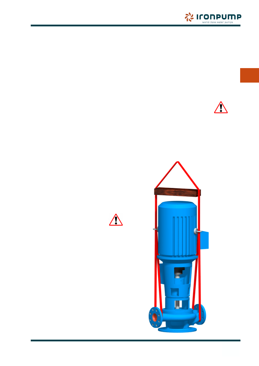
3.4
Lifting instruction
Straps are mounted around the flanges.
•
(Lifting chains might damage the surface
of the pump, and are not recommended).
A wooden bar is placed above the motor to
guide the strap.
If the motor has lifting eyes at the top, these
•
can be used to guide the pump so it does
not tip. Otherwise a strap fixes the motor.
3. INsTALLATIoN
8
3
Installation
3. INsTALLATIoN
3.5
Foundation
The pump must be fixed to a rigid foundation
which is substantial enough to absorb vibrations
and to take up stress from the hydraulic strain
and loads from the pipelines.
The pump should be installed with sufficient
accessibility for inspection and maintenance.
The surface of the foundation where the
pump is installed must be level and horizontal.
Damage due to an inadequate or faulty
foundation is not covered by the guarantee.
3.6
Environment conditions
Standard pumps are intended for installion in
dry rooms free from aggressive atmosphere
in temperatures between + 10 and 40
o
C
Installing the pump in other conditions (e.g.
outdoors, in damp rooms etc.) is only allowed
if this is stated in the technical data sheet.
3.7
Piping
Suction and pressure lines must be connected
to the flanges of the pump, free from strain,
as any stresses are taken up at fixed points,
and suitable compensators should therefore
be installed in the pipe system. The flanges
between which the pump is installed must be
absolutely parallel.
To keep pressure loss and flow resistance at
a minimum, tight bends and substantial size
reductions in the piping system should be
avoided.
Loss of pressure in the suction line must be
kept at a minimum in order to avoid cavitation
in the pump. Static suction height + loss of
pressure in the suction line + NPSH value for
the pump + steam pressure must not exceed
10 mWc at sea level. Long suction pipes that
make air pockets possible should be avoided.
3.8
Piping connections
Before installing the pump, the entire piping
must be pressure and leakage tested and
flushed clean before it is connected to the
suction and discharge side of the pump. If
the pressure test takes place with the pump
installed, the testing pressure must not exceed
the testing pressure of the pump, which is
stamped into the pump, usually in the suction
flange. The pump’s gaskets or flanges for the
mechanical shaft seal might otherwise be
damaged.
Check that all other connections to the pump
are in working order, such as lubrication,
priming, heating, cooling media outlet, etc.,
and that the various measuring equipment
has been correctly connected. Take care that
no parts obstruct easy access to the pump for
inspection or replacement of important parts.
3.9
Electrical installation
Connect the cables according to local electrical
regulations and standards, and by authorised
skilled stuff. The pump should be connected
to a motor starter.
Check that there is enough cable to allow the
motor to be removed without disconnecting
the wires. A switch (emergency stop) must be
installed close to the pump.
Kilowatt ratings are given in the pump Technical
data sheet.
3.10 Recommended accessories
As the pump, especially the mechanical
shaft sealing, is designed to run with clean
water without sludge, a suitable filter must be
installed in the suction line.
IRON Pump A/S can supply suitable filters.
9
4. opErATIoN
Operation
4
4. opErATIoN
4.1
Start-up procedures
Ensure that the pump and motor are mounted
according to instructions, all connections are
correct and the necessary screens and guards
are in order.
Check the direction of rotation (marked
•
with an arrow). The motor must turn in the
direction in which the arrow is pointing. If
the direction is wrong, the connections to
the terminals of the electric motor should
be changed.
Check that the pump can be turned by
•
hand.
Check that the motor has been lubricated
•
with grease.
Make sure that the piping is clean and free
•
from foreign objects. Liquid should flow
regularly into the pump.
Check that the pump and suction pipe are
•
filled with liquid. Any air or gas must be
carefully released before start-up.
Check the pump for noise and vibrations
•
immediately after starting. At the normal
head it should have a steady motion
without unusual noise and vibrations after
one minute.
Check the priming device (if any).
•
Check the seal housing for leakages.
•
4.1.1
Pumps with Priming device
Pumps provided with a mechanical priming
pump should be checked for supply/content of
liquid before starting.
The valve on the discharge side of the pump
must be closed during priming.
The operating instructions for the priming
system should be strictly followed (See
Chapter 8).
After priming the pump, open the valve on
the discharge side slowly and adjust it in such
a way that the permissible vacuum is not
exceeded.
4.2
Starting the pump
When the pump is ready, it is started with the
discharge valve closed. After starting, the
discharge valve is slowly opened until the
working point is reached. If the pump runs with
closed valves for a period of the time, it should
be equipped either with temperature control
equipment or recirculation. Running with the
valves closed for a long period can damage
the pump.
Check bearing temperature (max. 105
o
C)
Do not run pump with closed valve on
discharge side for prolonged time.
4.3
Stand-by
If the pump is going to be on stand-by for a
long period, it must be started or rotated at
least once a week to avoid damage to the
mechanical seals.
4.4
Pump vibrations
During operation, be aware that significant
vibrations have a major affect on the pump’s
performance. If vibrations are significant the
pump should immediately be turned of to be
able to locate possible errors.
Never operate the pump without
the coupling guard .
4.5
Lubrication
The pump bearings are closed and not
supposed to be greased.
The motor bearings are greased according
the motor instructions.
4.6
Frost protection
If there are any risk of freezing of the liquid in
the pump, removing the drain plug empties the
pump casing.
10
4. opErATIoN
Operation
4
5.1
Inspections
Before any inspection and maintenance of the
pump, the operator must ensure that the pump
cannot be unintentionally started. The pump
must be stopped, and all electronic contacts
must be disconnected.
The system must be de-pressurized and the
pump must be emptied of liquid. If the pump
has been pumping hazardous liquids, the
liquid must be collected, and the pump should
be flushed with clean water or another suitable
liquid.
It is important to ensure that
the pump does not contain
dangerous amounts of
corrosive, toxic or similar
substances when maintenance
is taking place.
5.1.1
Three-month inspection
Check suction and discharge pressure.
•
Check for unusual noise, vibrations and
•
leakages.
Inspect the motor as per the instructions
•
from the manufacturer.
The mechanical seal must be inspected
•
for leaks by normal pressure at the suction
side. The seal must not leak either during
stand-by or during operation .
Check that the circulation pipe for the
•
mechanical seal is not blocked
If any faults are found during inspection, they
must immediately be corrected, since any
defects can be of major importance for the
functioning of the pump and its life spare.
5.1.2
Twelve-month inspection
Disassemby of the pump is required.
•
Take the pump apart (See 5.2). The
•
rotating parts are checked and repaired if
necessary.
Check the clearance between the impeller
•
and casing wear ring. Normal clearance
is 0,45-0,50 mm. Maximum clearance is
0,8-1,0 mm. depending on the Size and
Capacity (See 5.5).
5.1.3
Lubrication
The pump bearings are greased for lifetime
and do not need no further service.
5.2
Assembly and Disassembly
Study the Spare Parts drawing for the
actual pump before starting disassembly
of the pump.
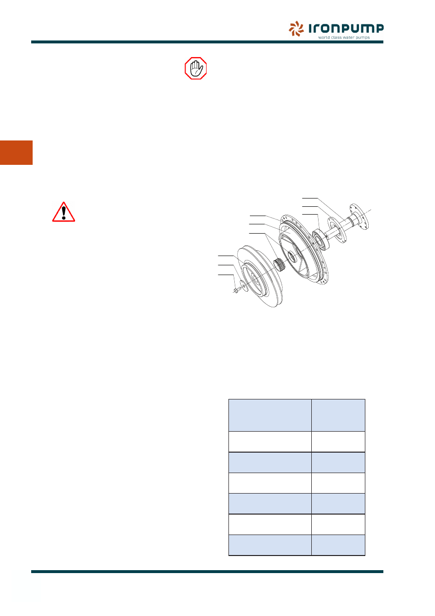
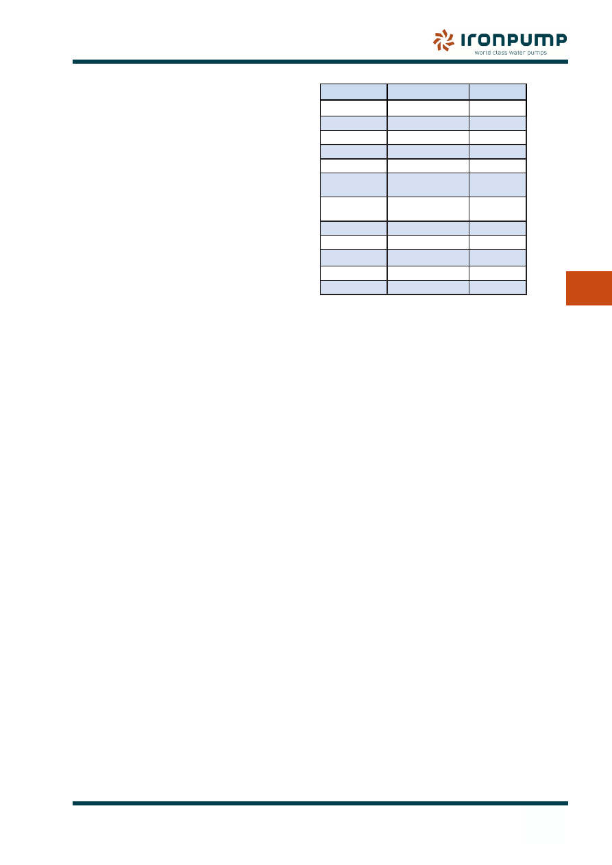
5.2.1
Rotating unit
Table. Weight of rotating unit
Pump size
(from-to)
Weight
kg
40-40/200-
125-125/250
22
50-50/25-
125-125/250
35
150-150/250-
200-200/250
40
80-80/315-
150-150/315
50
200-200/315-
250-250/3150
60
200-250/400-
300-300/400
94
554
230
906
161
433
321
360
210
412
Spare Parts list
Item
Casing cover
161
Shaft
210
Impeller
230
Radial ball bearing 321
Bearing cover
360
Spare Parts list
Item
O-Ring
412
Mechanical seal
433
Washer
554
Impeller screw
906
11
5. mAINTENANCE
Maintenance
5
5. mAINTENANCE
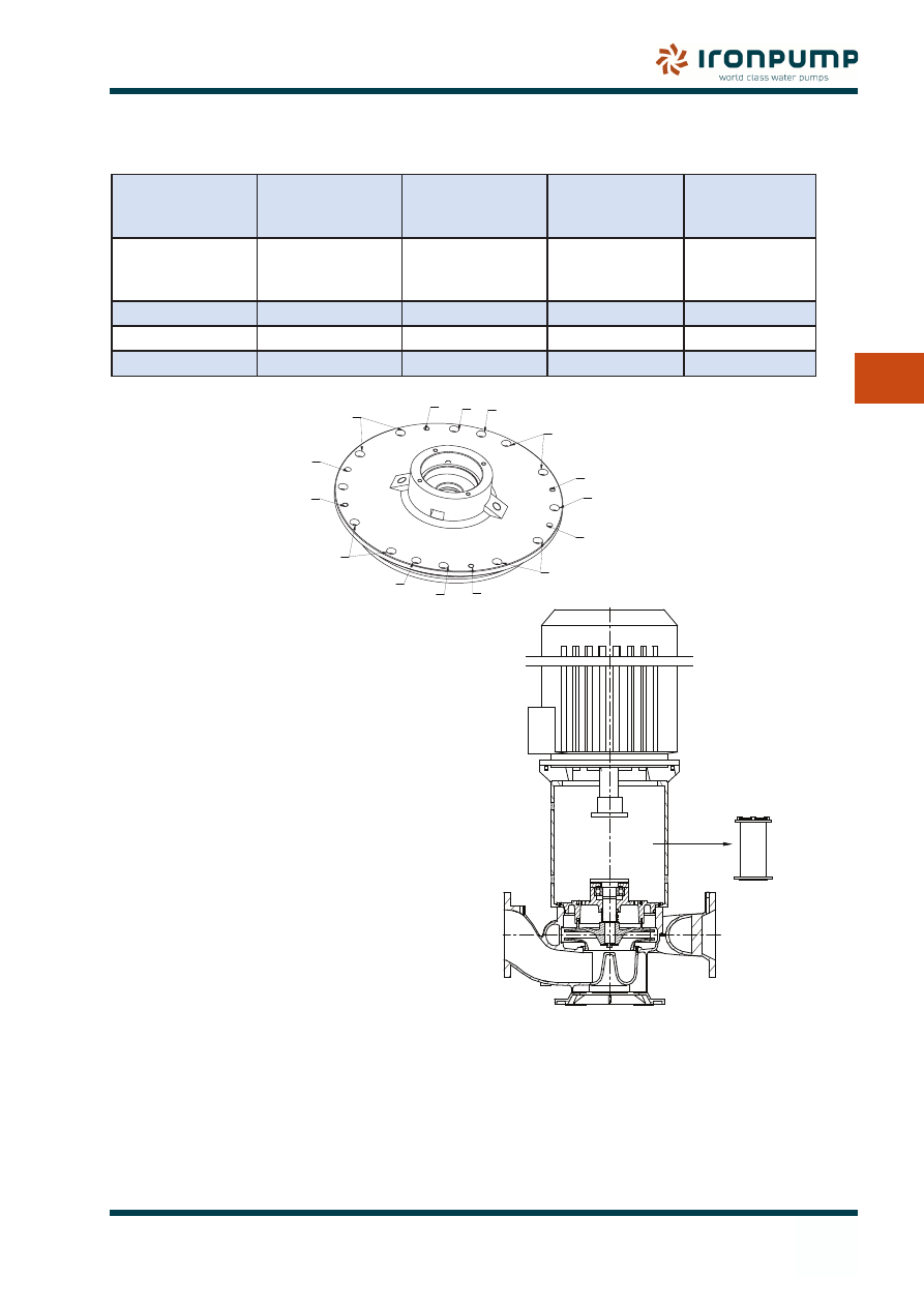
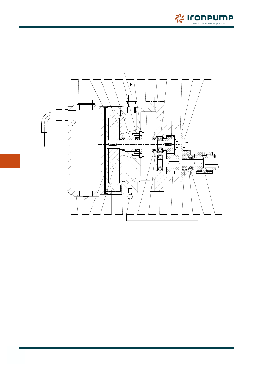
5.2.2
Disassembly DHBS/DHBF
Table for holes in the casing cover (Item 161)
Threaded hole
for
Threaded hole
for puller bolt
Free hole
in cover
Mounting
hole in cover
Mounting
hole in cover
Dismantling of
cover from motor
stool
Dismantling of
motor stool from
pump casing
Fixing of
motor stool in
pump casing
Fixing of cover
in motor stool
Fixing of cover
in pump casing
A
B
C
D
E
2xM8
2xM8
2xM8
2xM8
12xM12
Max 5 NM
Max 5 NM
10 NM
10 NM
15 NM
Without removing motor:
The rotating unit can be removed without
removing the motor:
Ensure that the pump has been drained of
•
liquid.
Remove circulation pipe (Item 710, Se 6.5)
•
Remove spacer bush (Item 860.6) and
•
coupling flexible steel disc (Item 867) , if
any.
Remove screws marked D+E.
•
Mount puller bolts in holes marked A and
•
lift the casing cover.
Lift the disconnected rotating unit and take
•
it out of the pump.
Gentle disconnection is recommended to
•
prevent any damage to the mechanical
seal. (Use a cloth or the like during of
disasembly/assembly of the rotating unit).
See 6.5
E
A
A
B
B
C
C
D
D
E
E
E
E
E
E
E
12
5. mAINTENANCE
Maintenance
5
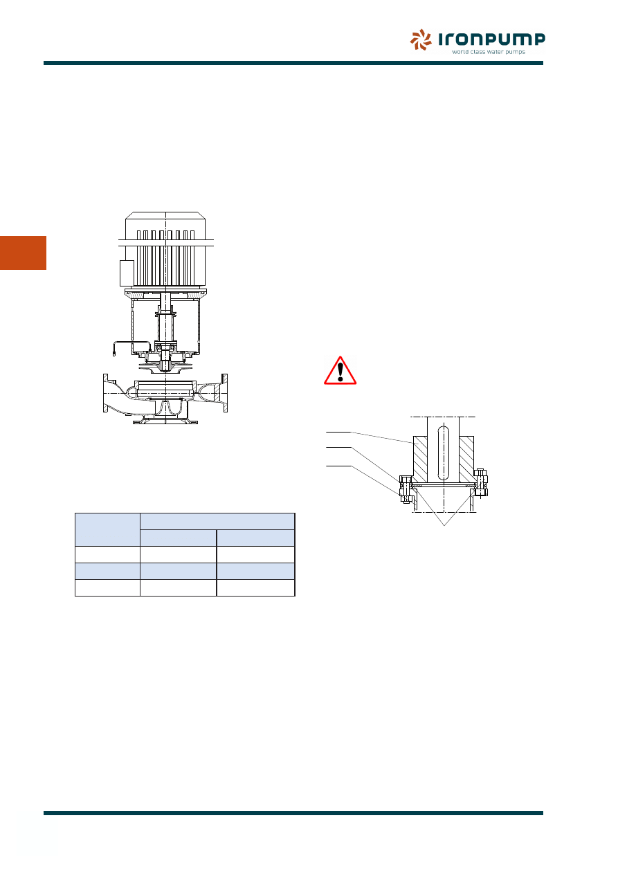
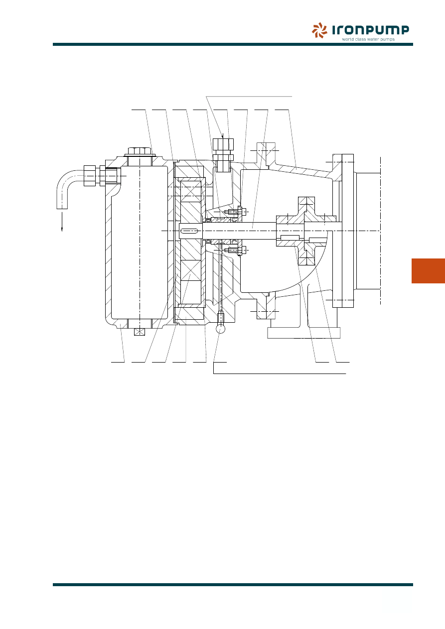
With removing motor:
Remove screws marked C + E
•
Remove the circulation pipe (pos. 710)
•
Mount the puller bolts in the holes marked
•
B
Lift the disconnected parts and remove
•
them.
Note:
On mounting the screws are tightened by
hand, then cross-tightened by moments as
stated, in order to balance the cover:
Holes
крепёжных моментов
Bolt size
Nm
C
2-M8
10
D
2-M8
10
E
12-M12
15
OBS! Number of E-holes depends on
pump size.
5.2.3
Assembly DHBS/DHBF
In order to prevent seizures in future repairs,
all joints and bolt threads should be treated
with an appropriate compound (e.g. “Never
Seez”) before assembly.
Before reassembling, clean the inside of
•
the pump casing and paint with appropriate
coating.
Assemble the pump in opposite order of
•
the disassembly (See 5.2.2)
Casing cover (Item 161), with the seat ring
•
of the mechanical shaft seal (Item 433),
must be fitted gently on the shaft
The O-ring (Item 412) must be fitted to the
•
cover.
The rotating unit of the shaft seal ( Item
•
433) is carefully placed on the shaft (Item
210).
The casing wear ring (Item 502) and the
•
impeller must be fitted and tightened by
screws.
Check the clearance between the impeller
•
and casing wear ring. (See 5.5).
Before any up-start, the shaft must be
•
turned by hand in order to check for any
blockages.
When the pump is assembled and all
•
bolts and nuts are in place, they can be
tightened.
5.3
Coupling
Never operate the pump without
the coupling guard .
Please NOTE!
Way of mounting the bolts!
(Only DHBF)
861.1
867
860.6
5.3.1
Mounting of coupling
with flexible steel disk (DHBF)
Clean the shaft ends, and check for burrs.
•
Heating of the coupling half (Item 861.1) to
•
approx. 80
o
C facilitates the mounting of it
on the shaft.
Mount the coupling half (Item 861.1) in line
•
with the motor shaft.
Lock the coupling half by the pivot screws.
•
Mount coupling flexible steel disk (Item
•
867), spacer bush (Item 860.6) and
coupling half (Item 861.1) , clamp the parts
and tighten the screws.
13
5. mAINTENANCE
Maintenance
5
5.3.2
Mounting of coupling
without flexible steel disk (DHBS)
The coupling part on the motor shaft
•
must NOT be axially fixed, considering
the thermal expansion it must be axially
movable.
Clean the motor shaft ends, and check for
•
burrs.
Lubricate the motor shaft end by “Never
•
Seez”, fitting paste or like and push the
coupling half (Item 861.1) up on the shaft
end.
Mount spacer bush (item 860.6) and
•
Coupling half (Item 861.1), clamp the
parts.
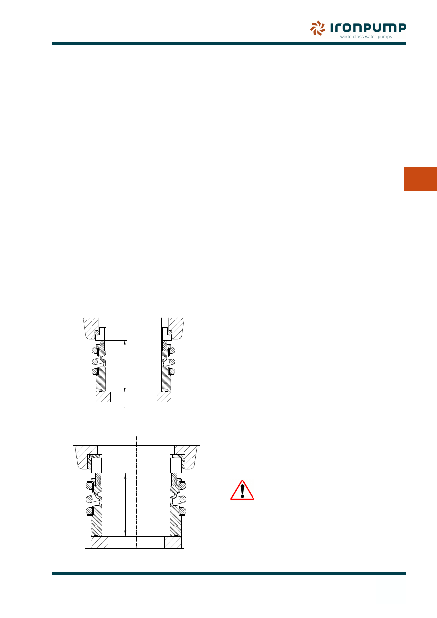
5.4
Fitting instructions for
Mechanical seals
A mechanical seal is a very high-precision
product and should be treated with the utmost
care before and during fitting. Do not unpack
until ready for use. The rotating wear ring and
the seat have been lapped to a high degree of
accuracy.
Fitting instructions:
Remove the protective packaging from the
•
seal, check for damage, and wipe clean.
Make sure that the pump is ready and
•
switched off.
The shaft should be clean and free of
•
burrs, and the machined place where the
seat fits must be cleaned very carefully.
Edges should be rounded so that they are
not sharp or penetrating.
Check that the shaft diameter corresponds
•
with the dimension of the seal within a
tolerance of 0.05 mm.
The bore in the casing cover (Item 161)
•
and the seat must be lubricated. Use
only liquid soap, soapy water or glycerine
with ethylene-propylene elastomer. The
elastomer must also be lubricated on
the inside where it slides on the shaft.
Lubricants containing silicone must never
be used.
Press the seat into position with your
•
fingers. If the space is tight, use a bush
when pressing the seat into position. Take
care not to damage the surface of the seat.
For example, use a piece of plastic for
protection between the bush and the seat.
After pressing the seat into position, make
sure that it is fully in place by measuring
the depth with a depth calliper.
Place carefully and by hands the rotating
•
part on the shaft.
Mount the impeller on the shaft.
•
The compressed length after fitting must
•
correspond to the working length of the
size of seal in question given in the table of
measurements.
Be aware of changes that can occur when
•
bearing arrangements and gaskets etc. are
replaced.
Before the pump is started it must be filled
•
with liquid and the air allowed to escape.
Air should be bled frequently during the
period after starting.
When fitting shaft seals, the
instructions should be read
carefully, especially when the
media is dangerous (poisonous,
hot, flammable etc.)
25(ø10-ø25)
41(ø42-ø60)
33.5(ø30-40)
IRON pump STANDARD
07.47.06E
33.5(ø30-40)
41(ø42-ø60)
25(ø10-ø25)
IRON/BURGMANN
07.47.06E
14
5. mAINTENANCE
Maintenance
5
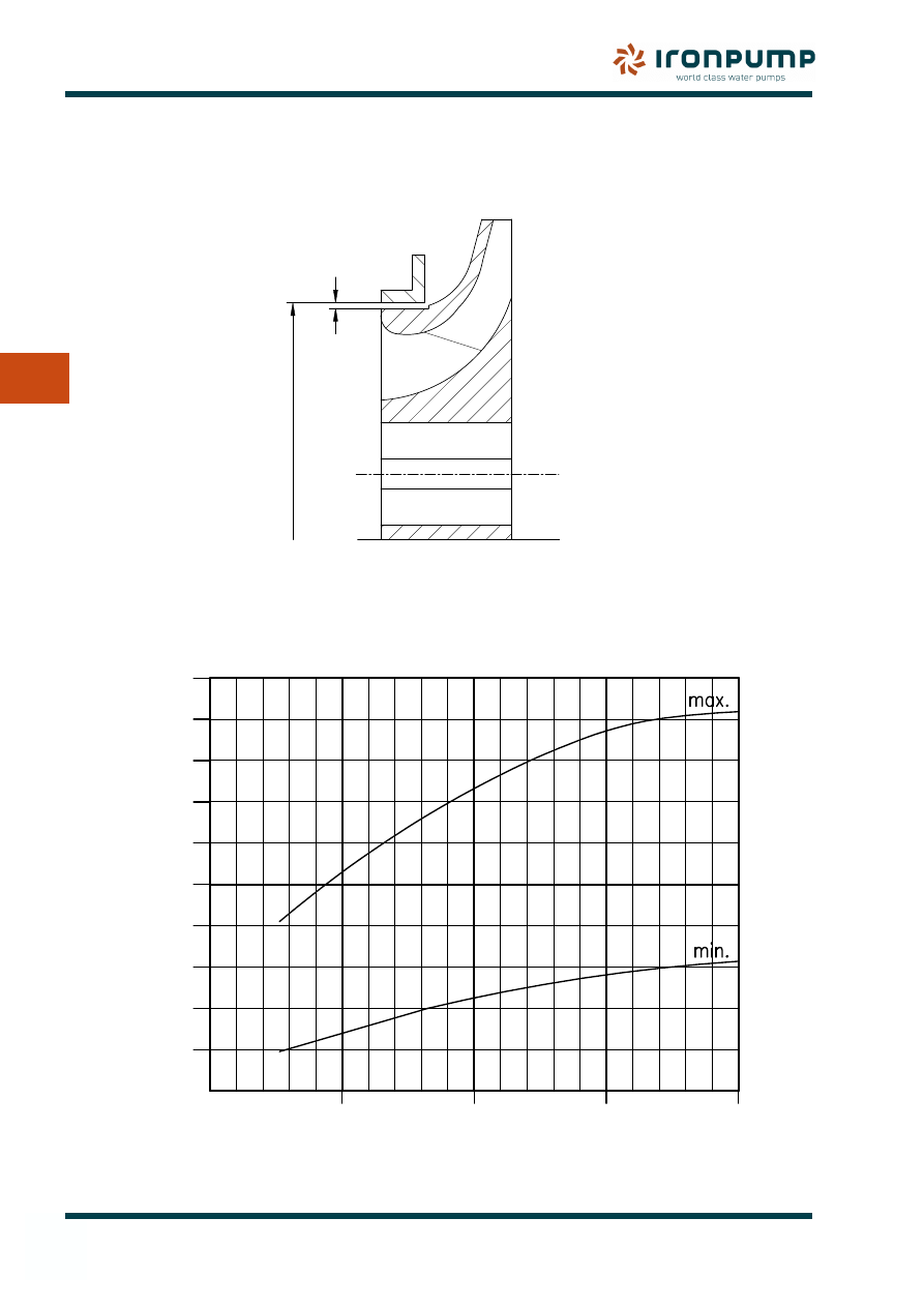
THE CLEARANCES STATED ARE AVERAGE VALUES,
AND MUST IN EACH SINGLE CASE BE COMPARED
WITH THE NEEDS FOR THE NECESSARY OPERATION DATA.
WEAR RING DIAMETER
0,1
0,2
0,3
0,4
0,5
0,6
0,7
0,8
0,9
1,0
100
200
300
400
CLEAR
ANCE (mm)
WEAR RING DIAMETER (mm)
22531E1
CLEAR
ANCE
5.5
Centrifugal pump wear ring Clearances
15
6. spArE pArTs
Spare Parts
6
6. spArE pArTs
6.1
Repairs
When ordering Spare Parts or requesting our
assistance, please advise the following:
Pump type
•
Serial number (i.e. P.no. DHB ####, from
•
Type plate, it is also stamped in the suction
flange)
IRON Pump A/S order number (5 or 7
•
digits.)
Item No. and description of part (See Spare
•
Parts drawing).
To establish the correct ‘diagnosis’, a brief
description of the breakdown is also required.
Spares are normally available from stock.
If you do the repairs yourself, you are requested
to follow the instructions regarding assembly
and disassembly or to contact our service
department.
6.2
Returning parts
Before returning parts to IRON Pump A/S,
please note that all liquids must be removed
and parts should be cleaned and neutralized.
The sender is liable for damage suffered by
the pump or other goods caused by leaking of
liquid during transport.
6.3
Decommissioning
Do not dump old or used parts. Metal parts
should be recycled as scrap or sent back to
IRON Pump.
When decommissioning the pump, it should be
neutralized and cleaned, and any hazardous
liquids,should be removed and sent to a
recycling facility.
None of the materials in the pump can be
considered hazardous, but we urge you to act
with care and to take the steps needed when
decommissioning the pump or its parts.
6.4
Table of Materials
Table of materials with the total content
calculated as percentage by weight.
DHBS/F
Description
Material
%
Pump casing
See Technical data
38
Casing cover
See Technical data
7
Shaft
AISI 329
4
Impeller
See Technical data
5,5
Casing wear
ring
See Technical data
0.6
Mechanical
seal
Carbon/ceramics
0.3
O-Ring
Viton
0.1
Foot
Cast iron
9
Motor stool
Cast iron
21
Coupling
Cast iron
2.5
Accessories
Steel
1
16
6. spArE pArTs
Spare Parts
6
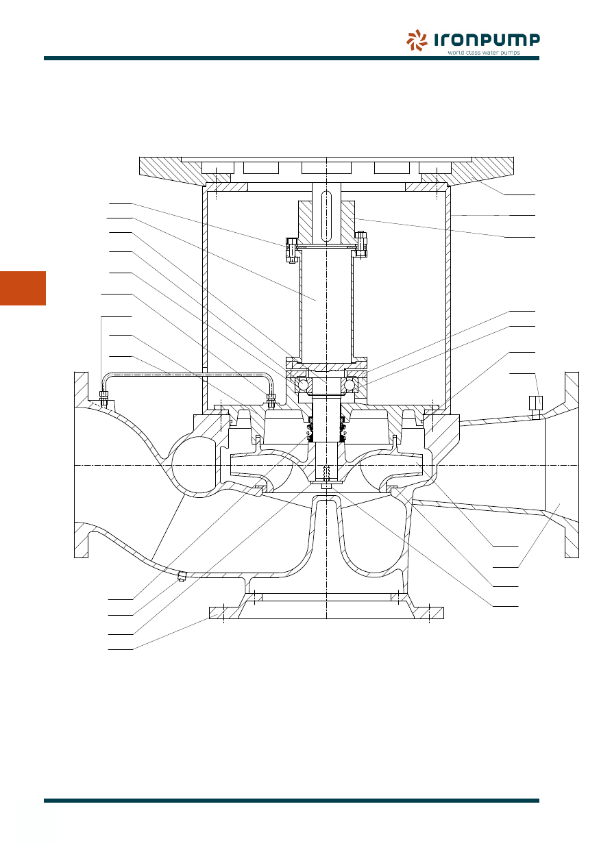
6.5
Spare parts drawing for DHBS / DHBF
Spare Parts list
Item. No.
Pump casing
101
Casing cover
161
Foot
182
Shaft
210
Impeller
230
Radial ball bearing
321
Motor stool
341
Motor stool, flange
341.1
Spare Parts list
Item No.
Bearing cover
360
O-Ring for pump casing 412
Mechanical seal
433
Casing wear ring
502
Loose collar
505
Washer
554
Pipe
710
Threaded pipe union
731.1
Spare Parts list
Item No.
Threaded pipe union
731.2
Spacer bush
860.6
Coupling half, incl. spacer 861.1
Coupling flex. steel disc 867*
Impeller screw
906
Plug for pressure gauge 910
Drain plug
912
Circlip
932
*) Only DHBF
906
28824E
502
101
230
910
412
505
861.1
341
341.1
On type DHBS
Item 861.1
must NOT be
axially fixed
360
731.2
731.1
710
161
(Only DHBF)
932
321
210
867
860.6
182
554
912
433
17
7. DATA
Data
7
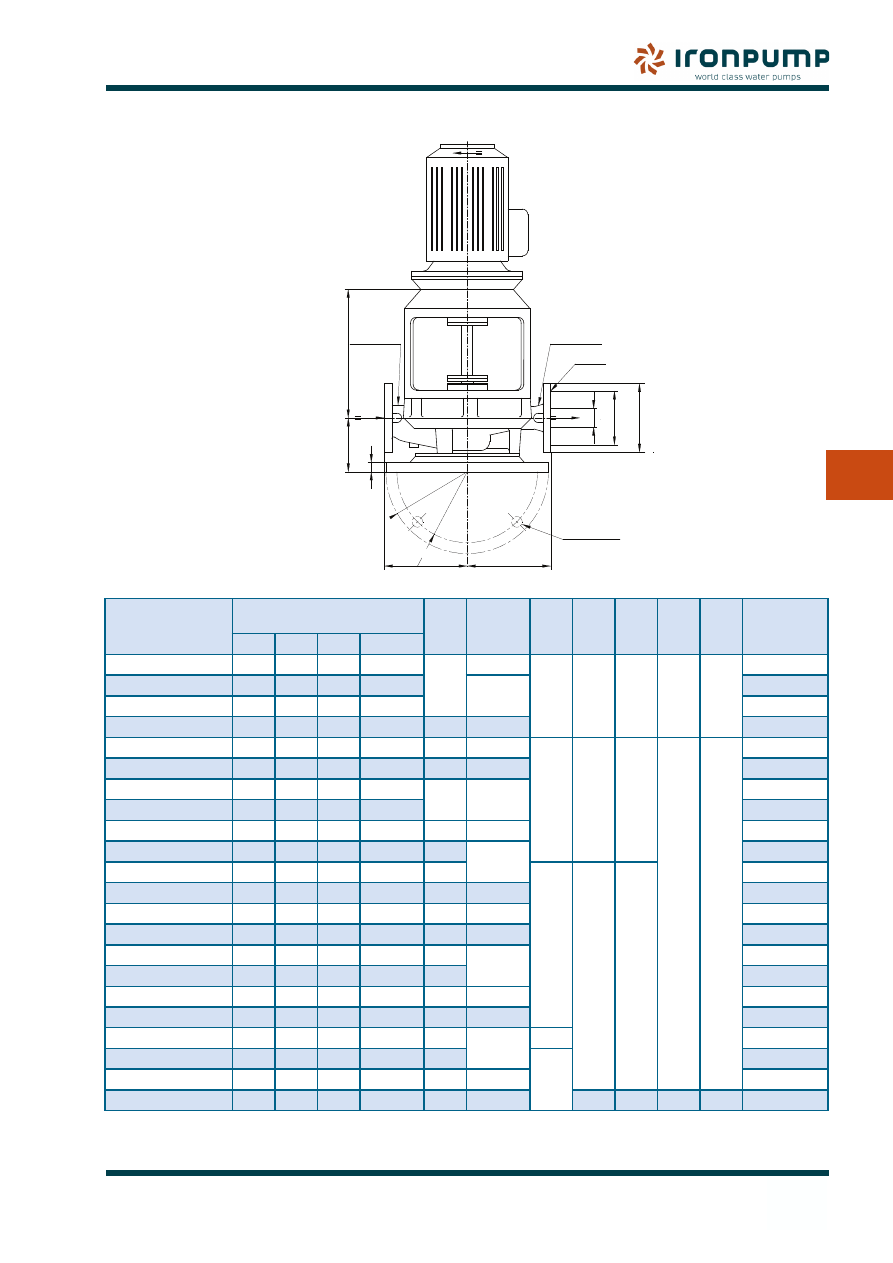
7.1
Type DHBS / DHBF - Dimensional drawing
7. DATA
Dimensions in mm
PUMP
SIZE
FLANGES
PN10, DIN 2501
A
B
E
F
M
øS
T
PUMP
WEIGHT
KG
NV
k
D
ød
40-40/200
40
110
150
4-ø18
125
180
370
280
330
20
18
75
50-50/200
50
125
165
4-ø18
200
80
65-65/200
65
145
185
4-ø18
87
80-80/200
80
160
200
8-ø18
140
225
91
100-100/200
100
180
220
8-ø18
175
250
380
380
440
24
25
111
125-125/200
125
210
250
8-ø18
205
280
121
50-50/250
50
125
165
4-ø18
145
225
135
65-65/250
65
145
185
4-ø18
126
80-80/250
80
160
200
8-ø18
160
250
131
100-100/250
100
180
220
8-ø18
180
280
134
125-125/250
125
210
250
8-ø18
210
460
460
520
181
150-150/250
150
240
285
8-ø22
235
355
228
200-200/250
200
295
340
8-ø22
280
450
232
80-80/315
80
160
200
8-ø18
175
280
207
100-100/315
100
180
220
8-ø18
180
315
217
125-125/315
125
210
250
8-ø18
200
224
150-150/315
150
240
285
8-ø22
220
355
232
200-200/315
200
295
340
8-ø22
315
450
284
250-250/315
250
350
395
12-ø22
335
500
495
369
200-200/400
200
295
340
8-ø22
280
750
408
250-250/400
250
350
395
12-ø22
335
560
451
300-300/400
300
400
460
12-ø22
400
630/560
560
630
26
30
721
The illustrated pump is with standard flange DIN 2501, PN10.
For the remaining dimensions, see dimensioned drawing of the pump.
1/4” PT
1/4” PT
4 - øS
øM
øF
B
B
E
A
BC=K
DN
ød
T
28650
D
18
7. DATA
Data
7
7.2
Troubleshooting
The diagram below describes the most common faults which can occur during operation of the
pumpunit. Should additional information be required, please contact IRON Pump A/S.
Problem
Possible cause
Pump and motor cannot be actuated:
Impeller or shaft blocked.
Motor fault.
Motor running but no pumping effect:
Motor rotation is not transmitted through coupling.
Discharge valve closed.
Non-return valve or other valves are closed.
Suction line closed.
Air in pump casing.
Suction line leaking.
Shaft seal leaking.
Bottom valve defective.
Suction lift too high.
Priming pump defective.
Insufficient capacity:
Wrong direction of rotation.
Number of revolutions too low.
Counter-pressure too high.
Suction line or impeller partly clogged.
Air in pump casing.
Air in pumping media.
Suction lift too high (inlet pressure too low).
Cavitation.
Suction line leaking.
Shaft seal leaking.
Pump worn out.
Pump pressure too high:
Number of revolutions too high.
Impeller oversized.
Specific gravity of pumping media too high.
Viscosity of pumping media too low.
Inlet pressure too high.
Manometer defective.
Capacity too large:
Number of revolutions too high.
Impeller diameter too big.
Counter-pressure too low.
Discharge head too low:
Number of revolutions too low.
Impeller diameter too small.
Specific gravity of pumping media too low.
Viscosity of pumping media to high.
Manometer defective.
19
7. DATA
Data
7
Problem
Possible cause
Power consumption too large:
Motor too small.
Motor fault.
Capacity too large.
Counter-pressure too low.
Electricity supply incorrect.
Pump output decreases or stops:
Suction line leaking.
Shaft seal leaking.
Increasing suction lift.
Filter clogged.
Cavitation.
Irregular running:
Bearings defective.
Motor fault.
Increasing noise level:
Cavitation beginning.
Air in pumping media.
Capacity too large.
Base bolts loosened.
Influences from pipe connections or base.
Leaks:
Cracks in pump casing.
Faulty assembly of pump.
Pipe connections leaking.
Bearing temperature too high:
Defective pump alignment.
Influences from pipeline.
Coupling half is not in line with the motor shaft.
Shaft bent.
Foreign bodies or impurities in bearings.
Pump wears out quickly:
Wrong pump in relation to liquid.
Cavitation.
Shaft bent.
Defective alignment.
Influences through pipe line.
Strong vibrations:
Impurities in pump.
Worn or loose bearings.
Operating the pump at a critical speed.
Unbalanced motor or rotating components.
Loose hold-down bolts or loose or damaged parts.
20
8. prImING sYsTEm
Priming System
8
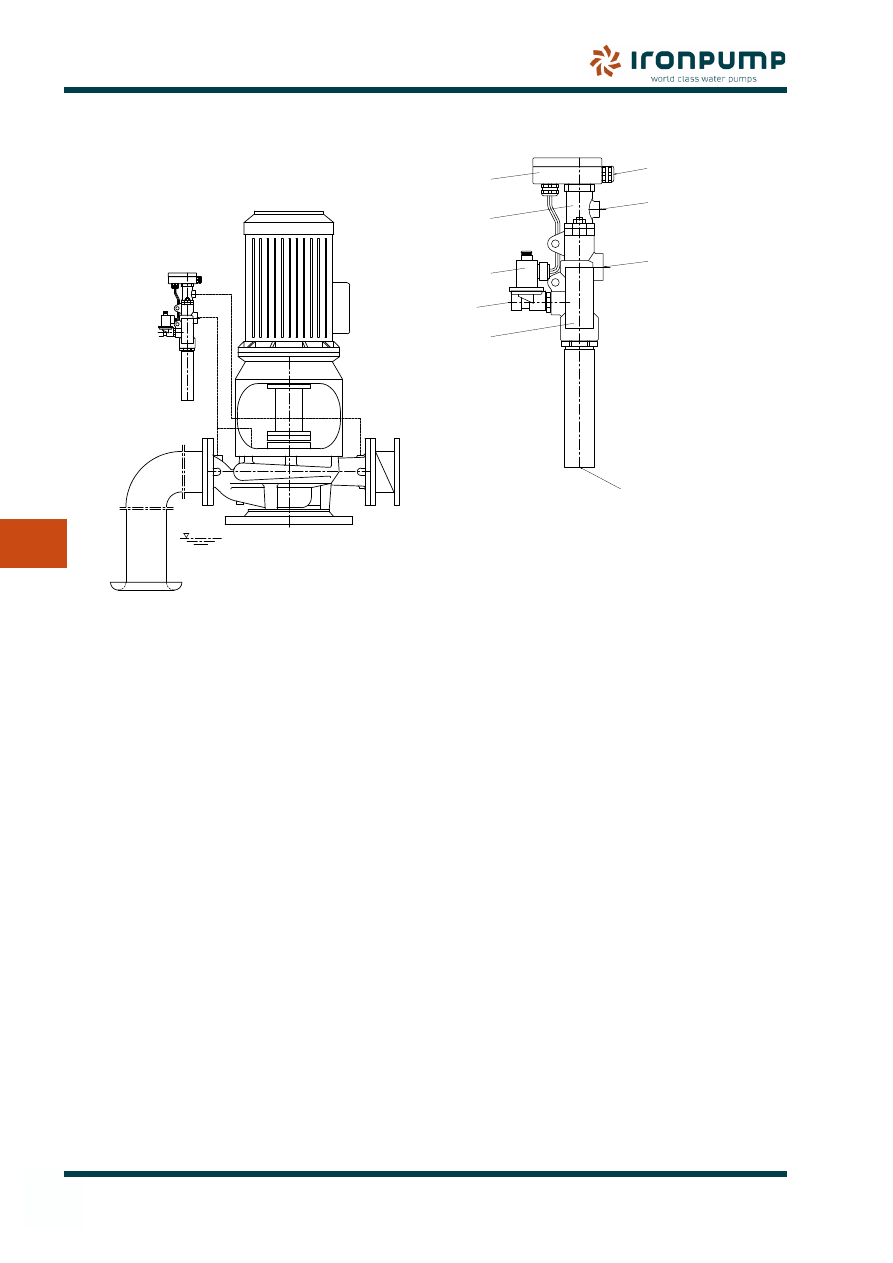
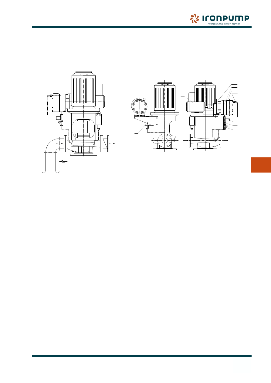
8.1
Priming of centrifugal pumps
IRON Pump A/S provides three different types
of priming systems for centrifugal pumps.
8.1.1
EA automatic ejector system
Automatic ejector-driven priming system
designed for centrifugal pumps, where dry
running is admissible for a short period of the
time and compressed air is available.
The ejector can be supplied in sizes 1/2” or
3/4” with different capacities. The pressure
controller can be set to fit the pump pressure.
8.1.2
VATEC automatic aspirator
Automatic aspirator designed for centrifugal
pumps where dry running is admissible for
short periods of the time and compressed air
is available.
The ejector can be supplied with different
capacities and different pressure switches for
different pump pressures.
8.1.3
PA automatic priming pump
Automatic priming system driven by a
mechanical vacuum pump. The system is
designed for centrifugal pumps where dry
running is admissible for a short period of the
time.
The pressure controller can be set to fit the
pump pressure.
8.1.4
Mounting of Priming devices
Priming devices must always be connected
to the highest point on the suction side of the
pump/suction line, and there must be no air
pockets in the suction line.
The valve on the pressure side of the pump
must always be closed during priming, or a
spring-loaded counter valve which opens as
soon as 60-70% of the working pressure is
reached must be installed.
The capacity of the priming pump must match
the volume of the pump and the suction pipe
which has to be primed, so that priming will
take no longer than 3 minutes.
8. prImING sYsTEms
21
8
8. prImING sYsTEm
Priming System
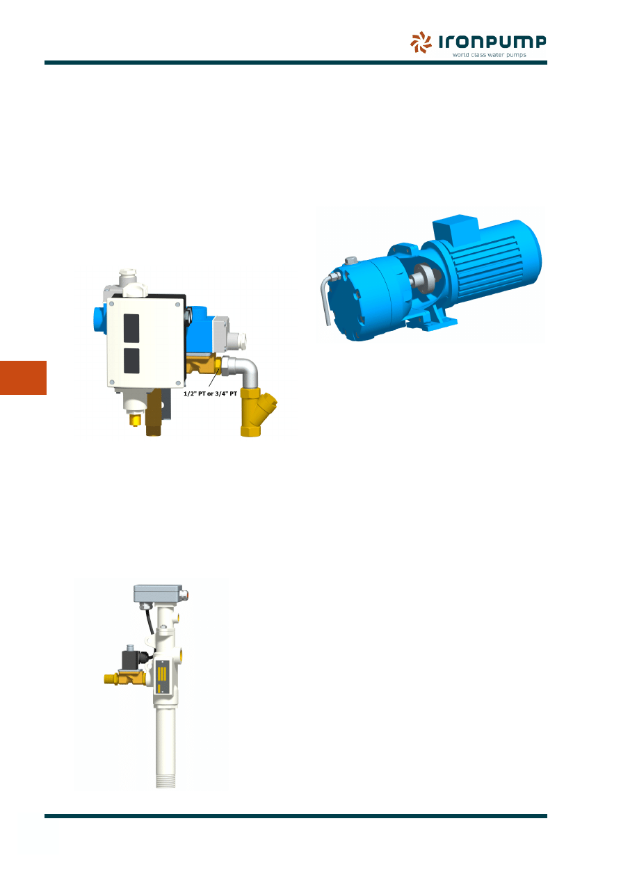
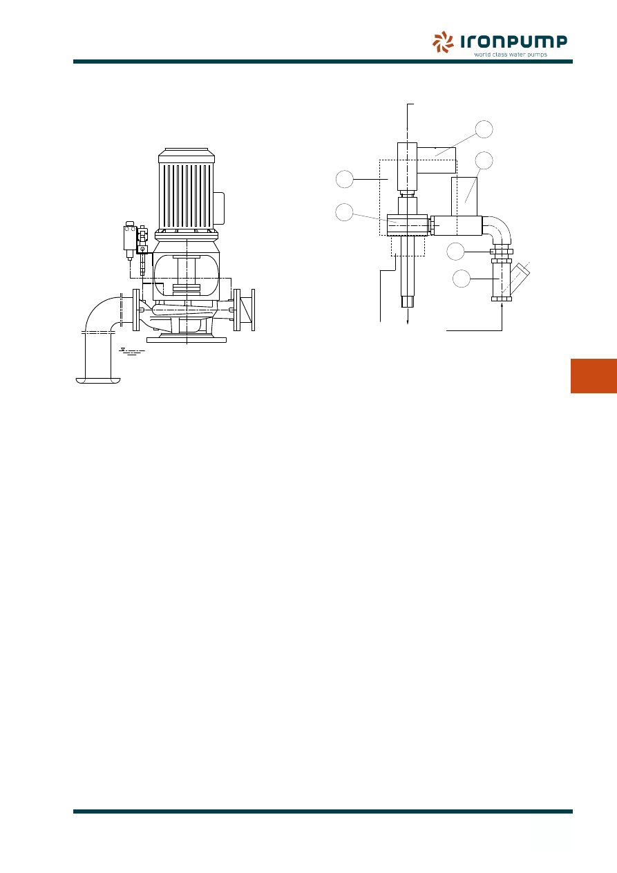
8.2
EA automatic ejector system
Automatic ejector system designed for
centrifugal pumps, where dry running is
admissible for short periods of the time.
EAinst11
8.2.1
Function
When the centrifugal pump is turned on, power
is also connected to the automatic ejector
system, and the ejector starts evacuating air
from the suction line and the centrifugal pump
through non-return valve (Item 4) and solenoid
valve (Item 1A).
On the discharge pipe of the main pump, a
spring-loaded counter valve must be mounted
which opens as soon as 60-70% of the working
pressure is reached. As soon as the centrifugal
pump has built up the necessary discharge
pressure, the ejector system is switched off
via the pressure switch. Should the discharge
pressure fall again during pump operation
through gas accumulation, the automatic
ejector system restarts for re-evacuation.
8.2.2 Design
Pressure-controlled priming system with a
compressed air ejector acting as a vacuum
generator.
Components:
Solenoid valve
Item 1
Solenoid valve
Item 1A
Pressure switch
Item 2
Air ejector 1/2” PT or 3/4” PT
Item 3
Non-return valve
Item 4
Filter
Item 5
8.2.3 Installation
The automatic ejector system must be fitted
above the highest point to be evacuated (eg.
the pump casing).
The ejector is supplied with compressed air
at 5-7 bar by solenoid valve (Item 1). The
compressed air passes through the ejector
whose suction side is connected to the suction
side of the pump through solenoid valve (Item
1A) and non-return valve (Item 4). The non-
return valve prevents the compressed air from
being led into the pipe system in the event of an
obstruction of the ejector outlet. The solenoid
valves are electrically connected so that both
valves are open at the current-carrying coil
and closed at the current-less coil.
lmpulse to the solenoid valve is controlled by
the pressure switch, which is connected to the
discharge side of the pump.
The pressure switch must be set to switch off
at 50-70% of the lowest working pressure. The
neutral zone must be set to at least 10% of the
working pressure (See 8.5).
Important note: outlet of air and water from
•
ejector must always have free access to
bilge.
Length of pipe - if any - to be very short.
•
Check that the filter (Item 5) is always
•
clean.
EA-INST4
P
ressur
e swit
ch
connec
tion
3
2
1
1A
5
4
Compressed air 5-7 bar
Outlet
From pump
1400 NL/min
1/2"PT
22
8. prImING sYsTEm
Priming System
8
8.3
VATEC automatic aspirator
Automatic aspirator designed for centrifugal
pumps where dry running is admissible for
short period of the time.
EAinst12
8.3.1
Function
When the centrifugal pump is turned on,
the automatic aspirator will be activated. As
soon as the centrifugal pump has built up the
necessary discharge pressure, the aspirator is
switched off via the pressure switch. Should
the discharge pressure fall again during pump
operation through gas accumulation, the
automatic aspirator restarts for re-evacuation.
8.3.2 Design
Pressure-controlled automatic aspirator with
a compressed air ejector acting as a vacuum
generator. With its polyethylene nozzle
system, the unit is resistant to a high degree to
aggressive fluids (e.g. seawater).
Components:
Compressed air ejector
with integrated shut-off valve
Item 1
Compressed air solenoid valve
Item 2
Pressure switch
Item 3
Terminal box
Item 4
8.3.3 Installation
Connections:
Casing air vent
Item A - G 3/4” PT
Exhaust
Item B - R 1 1/4” PT
Pressure switch
Item C - G 3/8” PT
Cable
Item E - 9 - 13 mm
Compressed air
Item P - G 1/2” (AELD
35-55) /G 1”(AELD 65)
The automatic aspirator is to be fitted above
the highest point to be evacuated (e.g. the
pump casing).
The highest point to be evacuated is connected
to connection A by means of an ascending air
vent pipe.
Exhaust nozzle B must not be shut off.
Compressed air is to be connected to
connection P via manual or controlled shut-off
valve.
The maximum installation height above the
lowest suction side fluid level is 6.5 m after
deducting the dynamic losses of the suction
system.
The pressure range is to be chosen by its
shut-off point, which must be under the lowest
working pressure of the pump. A later change
to another pressure range takes place by
changing the pressure switch module.
E
C
A
B
P
Vatec
1
2
3
4
Exhaust
23
8
8. prImING sYsTEm
Priming System
8.4
PA automatic priming system
Automatic ejector system designed for
centrifugal pumps, where dry running is
admissible for a short period of the time.
PA inst7
8.4.1 Function
When the centrifugal pump is turned on,
power is also connected to the automatic
priming system and the priming pump starts
evacuating air from the suction line and the
centrifugal pump through non-return valve
(Item 6) and solenoid valve (Item 5). On the
discharge pipe of the main pump, a spring-
loaded counter-valve which opens as soon as
60-70% of the working pressure is reached
must be installed.
As soon as the centrifugal pump has built up
the necessary discharge pressure, the priming
pump is switched off via the pressure switch.
Should the discharge pressure fall again during
pump operation through gas accumulation, the
priming pump restarts for re-evacuation.
8.4.2 Design
Pressure-controlled priming system with a
priming pump acting as a vacuum generator.
Components:
Vacuum pump
Item 1
Gearbox (for 50Hz systems)
Item 2
Motor
Item 3
Pressure switch
Item 4
Solenoid valve
Item 5
Non-return valve
Item 6
Filter
Item 7
Outlet to bilge
Item 8
Water tank
Item 9
The power output of the motor is 1.5 kW at
1450 RPM and 1.25 kW at 1750 RPM.
8.4.3
Installation
The priming pump is to be fitted above the
highest point to be evacuated (e.g. the pump
casing).
The impulse to the priming pump and the
solenoid valve is controlled by the pressure
switch, which is connected to the discharge
side of the pump.
The pressure switch must be set to switch off
at 50-70% of the lowest working pressure. The
neutral zone must be set to at least 10% of the
working pressure. (See 8.5).
Important note:
Outlet (Item 8) of air and water from priming
•
pump must always have free access to
bilge.
Length of pipe - if any - to be very short.
•
Check that the Filter (Item 7) always is
•
clean.
Before starting:
Check that the water tank (Item 9) in the
priming pump is filled with water.
Painst8
9
1
2
6
5
8
7
3
4
24
8. prImING sYsTEm
Priming System
8
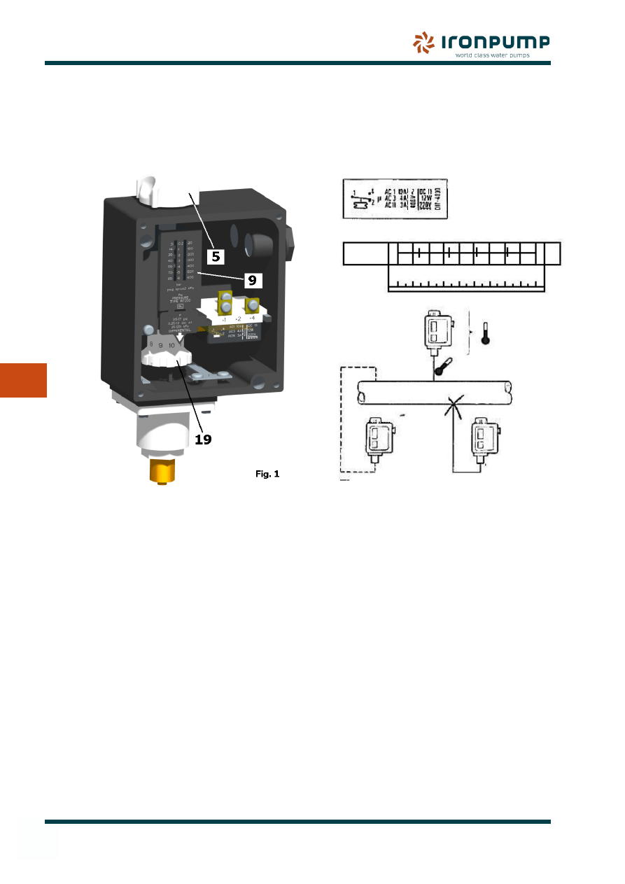
Data
Pressure controller type RT 200, max. test
pressure 25 Bar.
Instructions
The pressure controller is set by rotating the
knob (Item 5), at the same time reading the
main scale (Item 9). (See Fig. 1).
The differential is set by rotating the differential
adjusting nut (Item 19) to the value indicated
by the use of the monogram (See Fig. 5). The
maximum operating pressure in thus the sum
of the setting pressure and the differential.
Example
To control a priming device for a pump with a
working pressure of 4 Bar.:
Minimum pressure (50%):
0.5 x 4 Bar = 2 Bar.
Differential:
0.1 x 4 Bar = 0.4 Bar.
Connect the priming device to terminals
•
1-2 of the pressure controller.
Set the pressure controller for 2 Bar by
•
rotating the knob (Item 5).
Set the differential adjusting nut (Item 19)
•
(See Fig.3) which is found by reading the
monogram (See Fig. 5).
8.5
Danfoss pressure controller for Priming systems
Bаr
RT 200
0.25
0.4
0.6
0.8
1.0
1.2
Мin.
Маx.
1
2
3
4
5
6
7
8
9
10
Fig. 5
Маx. 70 С
Мin. -40 С
Маx. 100 С
о
о
о
Fig. 4
Bаr
RT 200
0.25
0.4
0.6
0.8
1.0
1.2
Мin.
Маx.
1
2
3
4
5
6
7
8
9
10
Fig. 5
Маx. 70 С
Мin. -40 С
Маx. 100 С
о
о
о
Fig. 4
Bаr
RT 200
0.25
0.4
0.6
0.8
1.0
1.2
Мin.
Маx.
1
2
3
4
5
6
7
8
9
10
Fig. 5
Маx. 70 С
Мin. -40 С
Маx. 100 С
о
о
о
Fig. 4
25
8
8. prImING sYsTEm
Priming System
2
1
1
1A
0
4
1
2
2
2
U
96
95
b
0
4
1
2
a
1
V
W
4
4
6
6
3
5
Main
Pump
Motor
Vatec
230V 50/60Hz
400V 50Hz
440V 60Hz
R S T
TO STARTER
P
440V 60Hz
400V 50Hz
IRON's SUPPLY
440V 50/60Hz
230V 50/60Hz
115V 50/60Hz
Pressostat
Danfoss
TO STARTER
Pump
Motor
Main
R S T
P
Danfoss
Solenoid Valves
TO STARTER
SHIPYARD's SUPPLY
Pump
Priming
Motor
Solenoid Valve
Danfoss
IRON's SUPPLY
whit
e
gr
een/y
ello
w
Pressostat
Danfoss
blue
Motor
Pump
Main
R S T
440V 60Hz
400V 50Hz
115V 50/60Hz
230V 50/60Hz
440V 50/60Hz
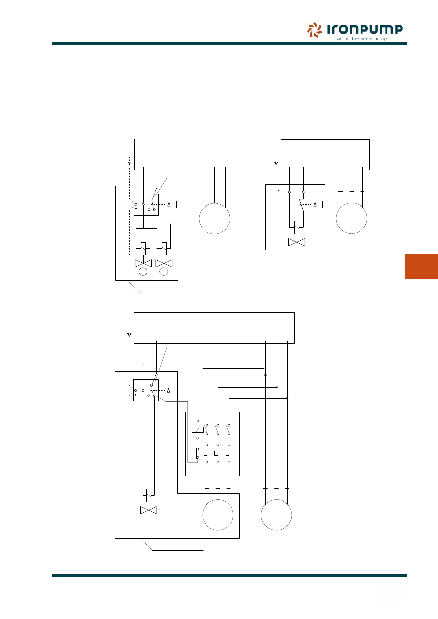
EA automatic ejector system
Type VATEC automatic aspirator
Automatic priming system Type PA
P
E010903
8.6
Wiring diagrams for Priming
systems
The customer is responsible for the wiring
being done according to valid regulations.
Care should be taken to ensure, before
connecting the coil to the mains, that the
voltage and the frequency of the coil are in
conformity with those of the mains; 10% over-
or under voltage is permissible in case of
normal frequency.
26
8. prImING sYsTEm
Priming System
8
Spare Parts list
Item No.
Pump casing
101.1
Suction casing
106
Wear plate
135
Shaft for pump
211
Impeller
231
Ball bearing
321
Bearing cover
360.2
Bearing cover
360.3
Bearing cover
360.4
Gasket
400.3
Joint ring
411
Shaft seal ring
420.3
Spare Parts list
Item No.
Shaft seal ring
420.4
Shaft seal ring
420.5
Bearing bush
545
Tank
591
Grease nipple
636
Oil level sight glass
639
Toohted coupling
845
Gear casing
871.1
Cover for gear casing
871.2
Gear wheel drive
872.1
Gear wheel
872.2
Shaft drive
877
8.7
Spare Parts drawing for P-pump with gear - 1450 RPM
P-PUMP, 1450 RPM - with gear
FROM SUCT. SIDE PUMP
OVERFLOW
Control oil level
once a month
Mobilgear 600 xp 68
Lubricate once a month with grease
17730
845
420.5
360.3
321
872.1
321
360.4
420.4
636
106
101.1
231
135
591
411
420.3
420.4
400.3
545
360.2
871.1
639
321
872.2
871.2
H
E
F
211
877
Mobilith SHC100 - 5 gram
27
8
8. prImING sYsTEm
Priming System
Spare Parts list
Item No.
Casing
101.1
Suction casing
106
Wear plate
135
Shaft for pump
211
Impeller - suction stage
231
Motor stool
341
Bearing cover
360
Gasket
400.3
Spare Parts list
Item No.
Joint ring for plug
411
Shaft seal ring
420.3
Shaft seal ring
420.4
Bearing bush
545
Tank
591
Grease nipple
636
Coupling motor side
861.1
Coupling pump side
861.2
8.8
Spare Parts drawing for P-pump – 1750 RPM
OVERFLOW
H
FROM SUCT. SIDE PUMP
420.4
411 400.3
E
420.3
545
360.2 211
341
Lubricate once a month with grease
Mobilith SHC100 - 5 gram
P-PUMP, 1750 RPM
101.1
591
135
231
636
106
15544
861.2 861.1
F
28
9. moTor
Motor
9
9.1
General information
The following instructions refer to all motors
delivered by IRON Pump A/S. Read these
instructions before you transport, install,
operate, maintain or repair motors.
Should additional data be required, consult
the manufacturer or an authorized service
workshop immediately.
IRON Pump A/S cannot be held responsible
for unauthorized use of the motor.
9.2
Inspection
If any damage is observed on delivery, please
notify type of damage immediately to the
transport company. It is important that the
motor is not put into operation if any damage
has been discovered.
Check that all data on the rating plate, especially
voltage and winding connection (star or delta),
are consistent with the order specifications
and pump provided by IRON Pump.
Some motors are protected against bearing
damage during transport by means of a locking
device which must be removed before putting
the motor into operation. When the device
has been removed, turn the shaft by hand to
ensure free rotation.
9.3
Insulation resistance check
Insulation resistance of motors can be lowered
considerably by moisture. Consequently
insulation resistance must be checked after
receipt and inspection or after extended
storage. Insulation resistance of the winding
must be measured to earth and between
phases at 25
o
C. The measured value should
normally exceed the reference value.
Windings should be discharged
immediately after measurement
to avoid risk of electric shock!
The insulation resistance of new winding
is above 10 MΩ. Insulation resistance is
temperature dependent, i.e. if the ambient
temperature is increased/decreased by 20
o
C,
the resistance is halved/doubled respectively.
If the resistance at room temperature is below
the reference value, the windings must be
oven dried at 90
o
C for 12-16 hours followed by
105
o
C for 6-8 hours.
9.4
Handling
9.4.1
Storage
Motors should always be stored in dry
conditions, free from vibrations and dust.
Always remember to store the unit in the
transportation packaging.
Unprotected machined surfaces such as shaft
ends and flanges should always be protected
with an anti-corrosive coating before being
placed in storage.
In order to prevent grease migration, it is
recommended that the motor shaft be rotated
periodically by hand. If the unit is stored for
more than one year, the bearings should be
checked for corrosion before the motor is
installed and put into operation.
9.4.2
Transportation
If the motor is fitted with cylindrical roller
bearings, the rotor must be fixed by use of a
suitable transportation locking device before
any transportation is carried out.
9.4.3
Lifting
Only suspend motors from the lifting eyes
provided. Do not attach any additional load to
the motor as the lifting eyes are only intended
for lifting the weight of the motor.
9.5
Installation
The motors are suitable for indoor installation.
The motors may be operated at heights of
1000 meters above sea level at ambient
temperatures of – 20
o
C to + 40
o
C. Exceptions
are specified on the rating plate.
9.5.1
Ventilation
Normal ambient temperatures should not
exceed 40°C (Marine standard +45 or +50°C)
if standard performance is to be achieved.
Check that the motor has sufficient airflow.
9. moTor
29
9. moTor
Motor
9
Ensure that no nearby equipment, surfaces or
direct sunshine radiate additional heat to the
motor.
9.5.2
Drain Holes
Make sure open drain holes face downwards.
Extremely dusty environments all require drain
holes to be closed.
Incorrect setup may cause damage to bearings
and shaft extensions.
9.5.3
Connecting the motor
Normal motor design has the terminal box on
top with cable entry possible from both sides.
Some motors are available with top-mounted
terminal boxes rotatable 4 x 90°, and some
with side-mounted terminal boxes.
Unused cable entries must be closed.
As well as main winding and earthing terminals,
the terminal box can also contain connections
for thermistors, standstill heating elements,
switches, or PT 100 resistance elements.
Voltage may be connected at
standstill inside the terminal
box for heating elements or
direct winding heating!
Connection diagrams for auxiliary elements
are found inside the terminal box cover or in
additional labels on the motor frame.
The capacitor in single-phase
motors can retain a charge that
appears across the motor
terminals even when the motor
has reached standstill.
Choose cable cross-sections in accordance
with the rated current. Unused cable entries
must be closed by compression glands.
The motor must be out of operation,
disconnected and secured against starting.
This also applies to auxiliary circuits (e.g.
heaters). Make sure that there is no voltage.
The supply cables must be connected
with special care to ensure permanent and
reliable contact. Use suitable terminals for the
connection cables. Supply cables must be
relieved of stress so that no cantilever loads
are exerted on the terminals.
Cable entries which are not used and the
terminal box itself must be sealed against dust
and water. In order to maintain the degree
of protection, always ensure that the original
gaskets are used and that the terminal box is
clean and dry when closing.
9.5.4
Direction of rotation
The motors are normally suitable for both
directions of rotation. Exceptions are indicated
on the rating plate by an arrow. For the desired
direction of rotation, the stator winding is
connected as follows:
Connection of L1,
L2, L3 to:
Direction of
rotation when
viewing drive end:
U1, V1, W1
Clockwise
W1, V1, U1
Counterclockwise
Mode of starting
and winding
Measures to
changing of
rotation direction
Direct-on-line starting and
pole-changing motors with
separate windings
Reverse connections at
motor or switchboard.
Star/delta starting and
pole-changing motors with
Dahlander winding
Exchange two supply cable
conductors at the incoming
supply to the contactor
combination
Test
To check the direction of rotation, quickly
switch the properly connected but uncoupled
motor On/Off.
9.5.5
Y/Δ starting
In order to avoid excessive transient currents
and torques before changing from Y to Δ,
wait until the starting current of the Y stage
has died down or change when rated speed is
reached. Centrifugal pumps are normaly not
suited for star/delta starting.
30
9. moTor
Motor
9
9.6
Repair and Maintenance
Before carrying out any work on the motor,
disconnect it and secure it against restarting.
In motors with greasing device, regrease
bearings with the motor running.
9.6.1
General Inspection
Inspect the motor at regular intervals.
•
Keep the motor clean and ensure free
•
ventilation airflow.
Check the condition of shaft seals and
•
replace if necessary.
Check the condition of connections and
•
assembly bolts.
Check the bearing condition by listening
•
for unusual noise, vibration measurement,
bearing temperature, inspection of spent
grease or SPM nipple monitoring.
9.6.2
Cleaning
Depending on local conditions, air passages
should be cleaned regularly.
9.6.3
Bearing maintenance and
lubrication
Before the First Start of the
motor it must be greased!
Observance of regreasing
intervals is vital for the
operational reliabilty of the
motors!
Under normal operating conditions, motors can
be operated between 2-4.000 hours without
maintenance depending on frame size and
rpm. The maximum period of maintenance-
free operation is four years. However, the
condition of the grease should be checked
occasionally even before this time limit. The
indicated number of service hours is only valid
for operation at rated speed. The bearings
should only be filled 2/3 since a complete
filling of the bearings and bearing covers with
grease leads to increased bearing temperature
and therefore to increased wear.
The ball bearings and the bearing caps
should be washed with petrol or benzene. If
necessary, replace the bearings. Half fill the
spaces between the ball and the roller track
as well as the grease compartments with
grease. Coat shaft bushings in the bearing
caps or end shields with a thin layer of grease.
Permanently greased bearings (2RS and 2Z
bearings) cannot be washed and regreased.
Such bearings must therefore be replaced. To
dismantle the bearings, use pressing screws
or other appropriate devices.
9.6.4
Bearings with regreasing device
and grease slinger
Regreasing interval and required quantity
of grease are indicated on the rating plate.
Bearings and bearing caps must be washed
with petrol or benzene after regreasing twelve
times.
With the outer bearing cap open but the inner
cap screwed on, the rotor should be turned
slowly and grease pressed in through the
regreasing device until approximately half the
empty space between the rolling elements an
the roller tracks is filled with grease.
9.6.5
Lubricants
When regreasing, use only special ball bearing
grease with the following properties:
When regreasing, use only special ball bearing
grease with the following properties:
Good quality grease with lithium complex
•
soap and with mineral or PAO oil
Base oil viscosity 100–160 at 40°C
•
Consistency NLGI grade 1.5–3 *
•
Temperature range -30° - +120°C
•
continuous.
*) For vertically mounted motors or in
hot conditions, a stiffer end of scale is
recommended.
Grease with the correct properties is available
from all major lubricant manufacturers.
Highly loaded or slowly rotating bearings
require EP grease.
31
9. moTor
Motor
9
The following (or similar) high performance
grease can be used:
Esso
Unirex N3
Mobil
Mobilith SHC 100
SKF
LGHQ 3
BP
Energrease LC 2
Shell
Albida EMS 2
9.6.6
Lubrication intervals
The lubricantion intervals are based on
a bearing operation temperature of 80°C
(ambient temperature of 25°C) An increase
in the ambient temperature raises the
temperature of the bearings correspondingly.
The table values should be halved for a 15°C
decrease in bearing temperature and may
be doubled for a 15°C increase in bearing
temperature.
Frame size
Two pole
design
Four and
multipole
design
112 to 315
2000 hrs
4000 hrs
355 to 400
2000 hrs
3000 hrs
9.7
Spare Parts and Repair
Any repair work within the guarantee
period is subject to approval by the motor
manufacturer.
When ordering Spare Parts, the full type must
be designated and the product code as stated
on the rating plate must be specified.
If the motor is stamped with a serial number,
this should also be given.
9.7.1
Rewinding
Rewinding should always be carried out by
qualified repair shops.
32
9. moTor
Motor
9
9.8
Troubleshooting
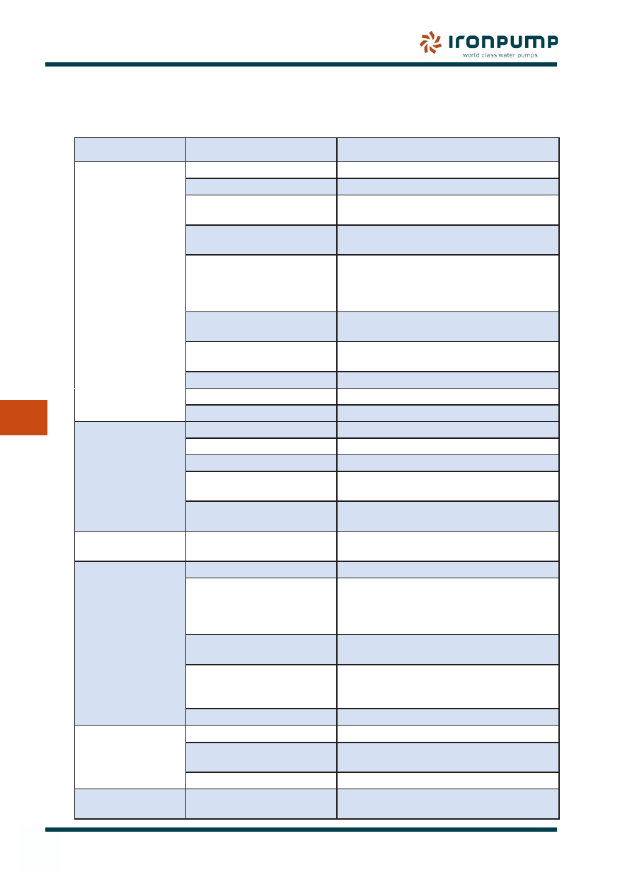
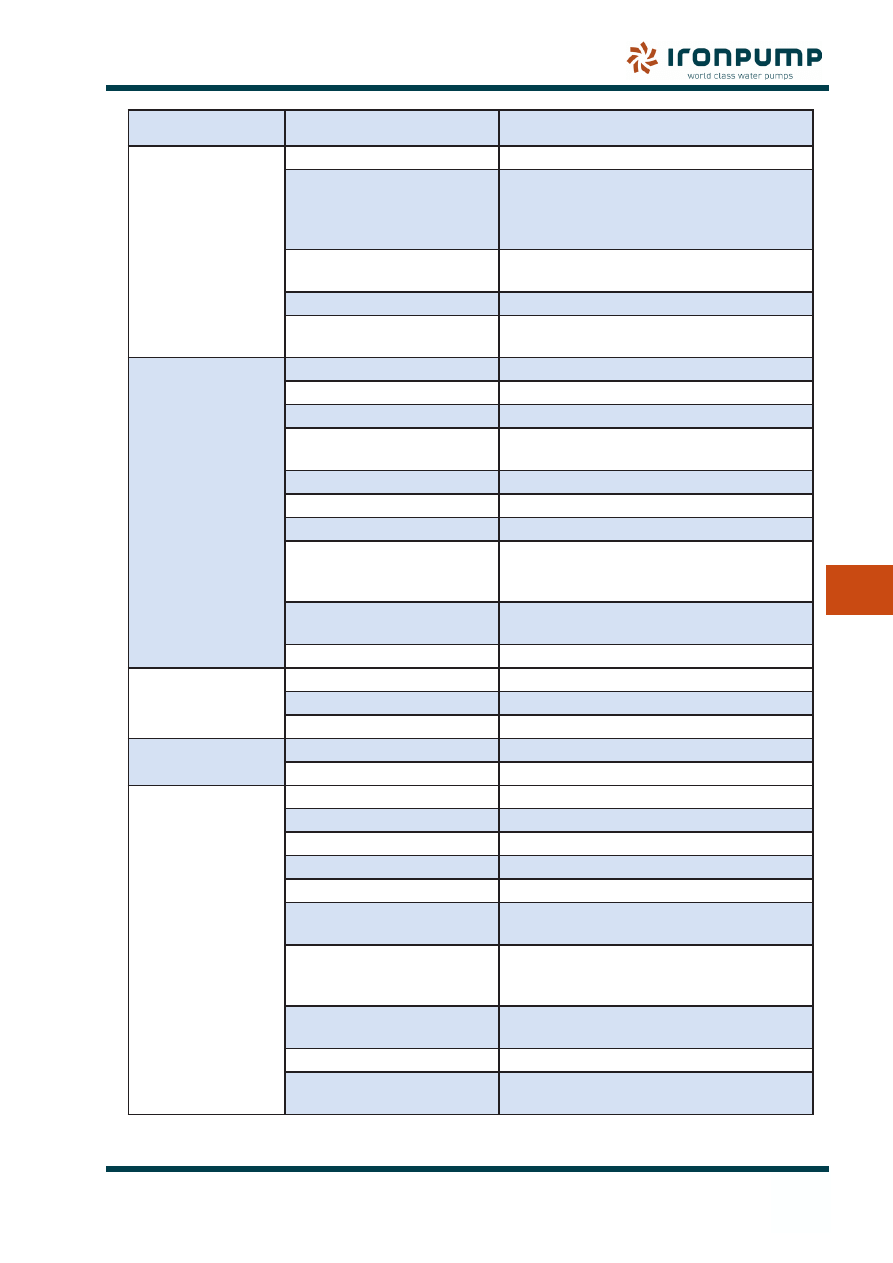
The diagram below describes the most common faults which can occur during operation of motors.
Should additional information be required, please contact IRON Pump or the motor manufacturer.
Problem
Possible cause
Solution
Motor does not
start:
Blown fuses.
Replace fuses with proper type and rating.
Overload.
Check and reset overload in starter.
Improper power supply.
Check if power supplied is consistent with
motor rating plate and load factor.
Improper line connections.
Check connections with diagram supplied
with motor.
Open circuit in winding or
control switch.
Indicated by humming sound when
switch is closed. Check for loose wiring
connections. Also ensure that all control
contacts are closed.
Mechanical failure.
Check if motor and drive turn freely. Check
bearings and lubrication.
Short circuited stator.
Indicated by blown fuses. Motor must be
rewound.
Poor stator coil connection.
Remove end bells, locate with test lamp.
Rotor defective.
Look for broken bars or end rings.
Motor may be overloaded.
Reduce load.
Motor stalls:
One phase may be open.
Check lines for open phase.
Wrong application.
Change type or size. Consult manufacturer.
Overload.
Reduce load.
Low voltage.
Ensure the rating plate voltage is
maintained. Check connection.
Open circuit.
Fuses blown, check overload relay, stator
and push buttons.
Motor runs and
suddenly stops:
Power failure.
Check fuses, control panel and lines for
loose connections.
Motor does not
come up to speed:
Not applied properly.
Consult supplier for proper type.
Voltage too low at motor
terminals because of line
drop.
Use higher voltage or transformer
terminals or reduce load. Check
connections. Check conductors for proper
size.
Starting load too high.
Check admissible load which motor is
supposed to carry at start.
Broken rotor bars or loose
rotor.
Look for cracks near the rings. A new rotor
may be required as repairs are usually
temporary.
Open primary circuit.
Locate fault with testing device and repair.
Motor takes too long
to accelerate and/or
draws high current:
Excessive load.
Reduce load.
Low voltage during start.
Check for high resistance. Adequate wire
size.
Defective squirrel cage rotor. Replace with new rotor.
Wrong rotation:
Wrong phase sequence.
Reverse connections at motor or
switchboard.
33
9. moTor
Motor
9
Problem
Possible cause
Solution
Motor overheats
while running under
load:
Overloaded.
Reduce load.
Frame or bracket vents may
be clogged with dirt and
prevent proper ventilation of
motor.
Open vent holes and check for a
continuous stream of air from the motor.
Motor may have one phase
open.
Check to make sure that all leads are
properly connected.
Grounded coil.
Locate and repair.
Unbalanced terminal
voltage.
Check for faulty leads, connections and
transformers.
Motor vibrates:
Motor misaligned.
Realign.
Weak support.
Strengthen base.
Coupling out of balance.
Balance coupling.
Driven equipment
unbalanced.
Rebalance driven equipment.
Defective bearings.
Replace bearings.
Bearings not in line.
Line up properly.
Balancing weights shifted.
Rebalance motor.
Discrepancy between
balancing of rotor and
coupling (half key - full key).
Rebalance coupling or motor.
Polyphase motor running
single phase.
Check for open circuit.
Excessive end play.
Adjust bearing or add shim.
Scraping noise:
Fan rubbing fan cover.
Remove interference.
Fan striking insulation.
Clear fan.
Motor loose on bedplate.
Tighten holding bolts.
Noisy operation:
Air gap not uniform.
Check and correct bracket fits or bearing.
Rotor imbalance.
Rebalance.
Bearing balls are
getting hot:
Bent or sprung shaft.
Straighten or replace shaft.
Excessive belt pull.
Decrease belt tension.
Pulleys too far away.
Move pulleys closer to motor bearing.
Pulley diameter too small.
Use larger pulleys.
Misalignment.
Correct by realignment of drive.
Insufficient grease.
Maintain proper quantity of grease in
bearing.
Deterioration of grease or
lubricant contaminated.
Remove old grease, wash bearings
thoroughly in kerosene and replace with
new grease.
Excess lubricant.
Reduce some grease. Bearing should not
be more than 1/2 filled.
Overloaded bearing.
Check alignment, side and end thrust.
Broken ball or rough races.
Replace bearing. First clean housing
thoroughly.
IRON Pump A/S
P.O. Box 527
Generatorvej 10
2730 Herlev
Denmark
www.ironpump.com
Service
Tel.
+45 4454 7111
Mob.
+45 2072 6788
Fax.
+45 4491 1644
service@ironpump.dk
Spare Parts
Tel.
+45 4454 7184
Mob.
+45 4077 6788
Fax.
+45 4491 0744
spare-parts@ironpump.dk
Spares
When requesting our assistance please make
sure to have the following information at
hand:
Pump type
•
Serial number (i.e. P.no. DHB ####, from
•
Type plate, it is also stamped in the suction
flange).
IRON Pump A/S order number (5 or 7
•
digits.)
Item No. and description of part (See Spare
•
Parts drawing).
If you need spares for your IRON Pump A/S,
you can also use the spare parts enquiry form
which can be found on our website.
Created by : IRJ Approved by: MM
Valid from: 2012-02-02
Revision : 4
Wyszukiwarka
Podobne podstrony:
eberspacher manual SAAB 9 3 eng
Manual eng
LOTR War in the North manual ENG
Manual B Speech RX2(eng)
Manual eng
Noktowizor manual nv 5x60 eng
NetBak Replicator Manual ENG Część14
NetBak Replicator Manual ENG Część11
NetBak Replicator Manual ENG Część5
NetBak Replicator Manual ENG Część13
NetBak Replicator Manual ENG Część1
NetBak Replicator Manual ENG Część9
Manual Samsung C3050 Eng Rev 1 0 090310
JBL HARMONY instrukcja manual (Eng )
NetBak Replicator Manual ENG Część12
więcej podobnych podstron