Where the Rubber Meets the
Road …….
Part III The Cylinder Head
By Dave Barnett
Vintage MG Club of Southern California
"The Torque Output of an
Engine is limited by just how
effectively we can make it
Breathe"
David Vizard 1985
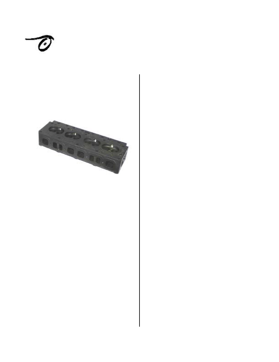
This month I will cover the XPAG
cylinder head. We will examine stock and
modified heads, to increase power, reliability
and yes even economy. For most of us,
rebuilding and modifying the cylinder head
should be left up to experienced engine
builders. You should make sure that the
company you are dealing with has the proper
equipment to perform the work. In this article
we will cover:
•
The inherent design chairestics of
a stock XPAG cylinder head
•
Modifications to increase
efficiency
•
After market cylinder heads
•
How to choose a shop that can
do the job right the first time
The inherent design characteristics of
a stock XPAG cylinder head
There is no question that the cylinder
head is where the power is made, it is in fact
the "Heart and Soul" of the engine. The design
of the XPAG head dates back to September of
1939 and was first used on the TB. There are
two basic design types. The "early" "Banana
Head" with short 1/2-inch spark plugs. Then
starting with XPAG/TD2/22735 a round water
hole head with used with longer-reach 3/4-inch
plugs. The thickness of a stock TC head is
76.65mm (3.018-inches) TD and TF XPAG
75.16mm (2.959-inch) TF XPEG 76.75mm
(3.021-inch)
(Source: MG Racers News Letter Code 106 by
Mike Lewis, Bayou Racing)
Understanding that in its simplest form,
the XPAG engine is nothing more or less than
an air pump. A useful step toward appreciating
an engines ultimate power limitation is air flow.
When an engines ability to draw in more air
with increasing R.P.M. ceases, so does the rise
in power. In other words, the engine has hit
peak power. Of all the restrictions existing in
an induction or exhaust system, the cylinder
head proves the greatest impediment to flow,
and ultimately the limitation of an engines
power output. Within the cylinder head itself it
is the valve size and location that is most
important not necessarily the size of the ports.
The XPAG head utilizes siamesed intake
ports, where two cylinders share a common
carburetor. A stud boss separates the ports. The
intake volume is approximately 90cc's. The
intake valve head diameter is 1.299 inches. The
seat angle is 30 degrees. It is very common
today to find seats ground at 45 degrees
however as pointed out in last months article
seats cut at 30 degrees provide a 23% area
advantage at lifts up to 0.150. This is
approximately one half of the total lift of a
stock valve.
The exhaust port is square and measures
1.65 inches on each side. It is almost the same
size as an early small block chevy. The valve
head diameter is 1.221 inches. The seat angle is
30 degrees.
Modifications to increase efficiency
The first step toward understanding
cylinder head porting is appreciating the
importance of being able to isolate and deal
with flow restriction. Airflow starts at the air
cleaner and continues through the exhaust. A
high restriction air cleaner will restrict flow and
fuel economy will be degraded. Using an APT
Tapered K&N offset filter for 1 1/4-inch or 1
1/2-Inch S&U carburetors, is the first step
toward improving flow. You get the highest
filtering capability with out impeding airflow.
K&N filters designed specifically for the 1 1/4
and 1 1/2 S&U carburetors can be purchased
from Advanced Performance Technology by
calling; 800-278-3278.
The same is true for the muffler. There is
a lot of backpressure in a stock muffler.
Although it is a straight through design, the
little round holes inside the muffler impede
flow. According to David Vizard, a flow rating
of 2.2-2.5 cubic feet per minute per horsepower
will allow the engine to produce close to the
same power as it does on an open exhaust. We
can accomplish this or come very close by
using a high flow large volume muffler like the
new Flowmaster "50" Series with Delta-Flow
technology.
Once we have the Goesintos and
Gooutas fixed we can now focus on the
cylinder head.
Selecting the right parts
Finding a completely stock XPAG
cylinder head not an easy task. Most have been
shaved to some degree to make the surface flat
or to increase the compression ratio. Measure
your head to determine how much material has
been removed. Remember that when you
increase the bore size, you will also increase the
compression ratio. Increasing the compression
ratio will also improve economy.
Cylinder Head Porting
In order to get a better understanding of
the process and components, we need to know
where to start. First we will examine the valve
ratios and size and determine what effect they
have on our XPAG. Second we will examine the
combustion chamber and how we can improve
performance by unshrouding the valves. Third
we will break the port down into 3 sections and
discuses various modifications that improve
flow.
Valve Ratios and Size
According to David Vizard on an engine
that uses siamesed intake ports the intake
should flow approximately 43% to 54% more
than the exhaust. Although I do not have the
flow-bench data for a stock cylinder head we
can see that the difference in diameter between
the intake and exhaust valve is only 0.078-
inches. This is a very small difference.
The XPAG engine Data Service
Supertuning Manual by W.K.F. Wood edited
by Jerry Austin 11/99, suggest using larger
valves in the Stage IA configuration. On a stock
engine, with a bore diameter of 2.6181-inch,
the larger valves don't have much clearance.
The centerline distance between the valves is
approximately 1.6-inches the radius for the
large intake is .7087-inche the exhaust valve
radius is .6693-inch together the overall
diameter is 2.978-inch. The bore diameter is
2.6181-inch. The difference is approximately
.359-inch. Although the net valve lift is
approximately .315 for a stock cam, it is
important to check clearances especially valve
to piston clearance, which should be no less
than 0.100-inch.
The Combustion Chamber
And
Unshrouding the valves
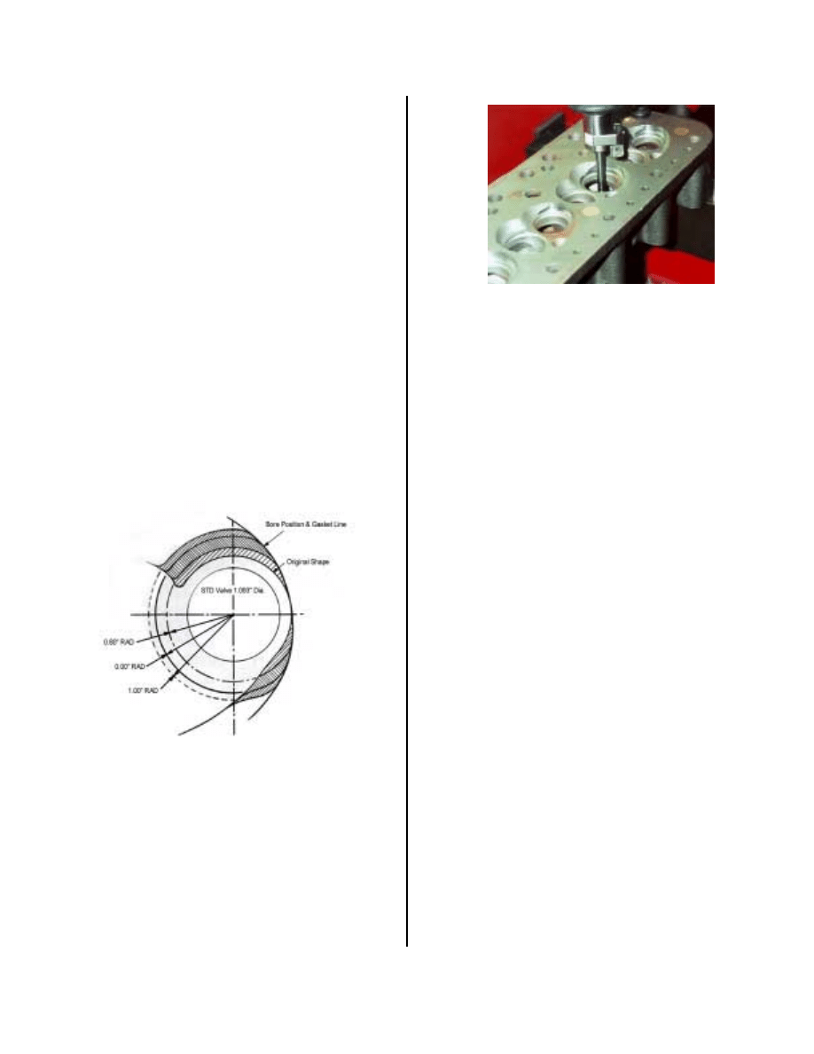
First just installing a larger valve does
not guarantee increased flow. In a test
conducted by David Vizard, using a SuperFlow
SF 300 Flow Bench, on an 850 Mini
combustion chamber revealed the following. In
an unmodified 850 combustion chamber,
changing the stock 850 valve 1.093-inch, with a
larger 1.5625-inch 1100 valve, the 1100 valve
showed slight improvements between 0.075
and 0.200-inch lift, but at lifts higher than 0.200
the smaller valve flowed approximately 20
C.F.M. more air @ 25" pressure drop at 0.315-
inch lift. By unshrouding the valve 0.800-inch
radius as shown below, gave a substantial
increase in flow. Therefore a smaller diameter
valve that has been unshrouded may provide
better flow that just installing a larger valve.
Effect on airflow when a closed chamber head is
unshrouded to varying degrees.
"Sweeping the Chamber" is a method
used to unshroud the valve. Cutting the
chamber to the outside of the cylinder can
increase the flow. It is done using the Serdi
100. Following any modifications to the
combustion chamber, the volume of the
chamber must be measured and the new
compression ratio calculated.
Sweeping the Chamber
Intake & Exhaust Ports
I wouldn't ever discourage anyone from
porting his or her own cylinder head. I have in
the past, ported Small Block Chevy heads using
"Porting Templates" to determine the various
shape of the ports and valve pocket. However
with the advent of modern equipment like the
Serdi 100, a shop can save you a considerable
amount of time, and at the same time provide
consistency from port to port or chamber to
chamber.
Since we are focusing on a street engine
and not a racing engine, I don't think that we
need to port the head using a flow bench. But it
could be a nice project to port one cylinder,
make a mold using Blue-Sil a special latex and
silicone combination and make porting
templates from the mold.
To establish where our priorities lie in
reducing flow restrictions, we can divide the
XPAG port into three (3) sections.
Section one is for all particle purposes, a
straight run toward the bowl area. The intake
port feeds two cylinders, and is divided by a
stud boss. This boss does not isolate the two
intake runners since it is open in the back.
Section two is where the two ports
merge. The intake valve for the number one
cylinder is open; the intake valve of the
second cylinder is closed. Each cylinder "sees"
the entire port area. This siamesed port has its
shortcomings. Care should be taken not to
sharpen the "beak" behind the stud boss, as this
will restrict flow. Instead, it should have a nice
radius and blend into the bowl.
I wish I could tell you the optimum
shape of the stud boss but I can't. This is an
area where a flow bench could be used to
determine the optimum shape. My cylinder
head has about the same radius in the front as in
the back. The problem with this design is that
the air from the closed valve moves very slow
as it collides with the faster mixture from the
port with the open valve.
Section three is the bowl area under the
valve. It is also referred to as the valve pocket.
You may have herd term "pocket porting" this
in conjunction with the valve seat is the most
important part of the port.
After market Cylinder Heads
If you would like to run a high
compression engine and not overheat the
engine. Or, instead of making a large
investment in a stock head, then the "Ultimate
Cylinder head modification for your XPAG
engine is an aluminum head". Offered by
Brown and Gammonds LTD, in the U.K..
What you get is brand new "Laystall
Lucas" aluminum head. The head is supplied
with a 40cc combustion chamber as that
provides an 8.0:1 compression ratio. On a
1250cc engine, or a 9.0:1 compression ratio on
a 1466 engine. A close look at the head shows
that the ports are approximately 0.5-inches
longer than stock. The major down side is that
this head is really expensive.
How to choose a shop that can do
the job right the first time
As many of us know, rebuilding our 50+
year-old engines is getting expensive. For this
reason it is my opinion that we should seek out
the most qualified vendors who know what they
are doing with our cylinder heads, and have the
right equipment to do a proper job.
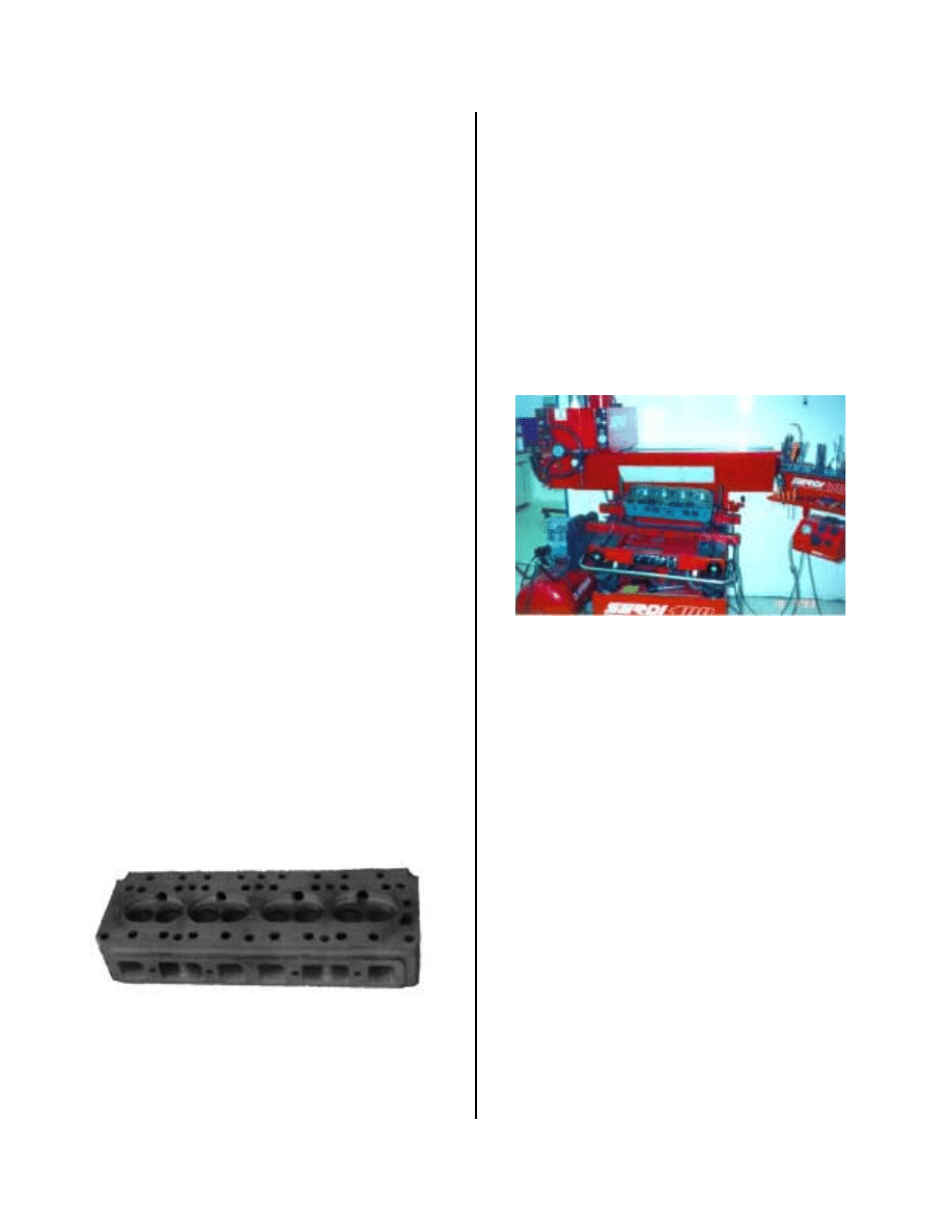
The Serdi Corporation manufactures one
of the best cylinder head valve seat and valve
guide machining systems. The Serdi 100 is a
self-centering valve-boring machine. The
cylinder head floats on a cushion of air until its
cutting head is perfectly aligned with the valve
guide, then it is locked into position for the
actual cutting process. This results in correct
alignment for the new valve seats with the
guide.
If you are looking for the best equipment this is it
Hales Automotive Machine Shop (714-
871-2054) located in Fullerton has a great
reputation for rebuilding the XPAG cylinder
head. A complete rebuild can be done for under
$250.00. According to John Seim " I've only
sent about 10 engine jobs (4 of my own) to him.
You might say that Alan Hail is an honorary
member of the VMG."
If you are looking for a shop that can
provide complete rebuild, porting services and
flow bench testing, then I recommend Advanced
Performance Technology. Although they
specialize in the MGA and beyond, they can do
an outstanding job on an XPAG head. This is
where I shop. They are located in Riverside
next to the K&N factory. Contact David Anton
at 800-278-3278.
Next month we will cover carburetors
intake and exhaust manifolds. Till then Happy
Motoring.
Document Outline
Wyszukiwarka
Podobne podstrony:
Głowica silnik DV4C
Kadłuby i głowice silników chłodzonych powietrzem, Samochody i motoryzacja, silniki spalinowe, P - k
Kadłuby i głowice silników chłodzonych cieczą, Samochody i motoryzacja, silniki spalinowe, P - kadłu
GŁOWICA SILNIKA, Samochody i motoryzacja, silniki spalinowe,
Głowica silnik DV4C
instrukcja obsługi samochodu lub cyfry wypisane na głowicy silnika
Wymontowanie i zamontowanie osłony głowicy silnika
Głowica cylindrów silnika D19T z systemem EGR 1994 rok (Volvo 440)
Trochę danych o silniku 1 9 D (XUD 9SD) montowanym oryginalnie w Nivie [ENG]
Opis wybranych bloków pomiarowych silnika VAG VCDS [ENG]
silniki prądu stałego
PODSTAWY STEROWANIA SILNIKIEM INDUKCYJNYM
04 Zabezpieczenia silnikówid 5252 ppt
SILNIKI GRAFICZNE W GRACH KOMPUTEROWYCH
chrystus jest zyciem mym ENG
SILNIKI
Prezentacja OP silniki
więcej podobnych podstron