1 - 13
CCNP: Optimizing Converged Networks v5.0 v5.0 - Lab 4-6
Copyright
© 2007, Cisco Systems, Inc
Lab 4.6 Class-based Marking, Shaping, and Policing
Learning Objectives
• Mark packets with DSCP values
• Implement class-based TCP Header Compression
• Configure class-based traffic shaping and policing
• Create and apply nested service policies
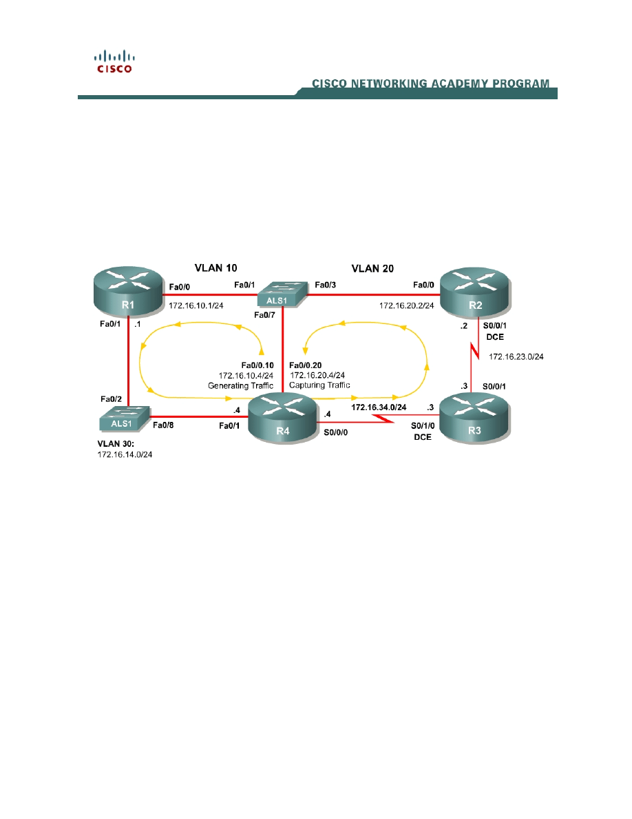
Topology Diagram
Scenario
In this lab, you will implement classification using network-based application
recognition (NBAR) using the Modular QoS CLI (MQC) to configure quality of
service on R1 and R2. You will configure class-based marking, shaping, and
policing mechanisms.
You should complete Lab 4.5 before beginning this lab because this lab will
build on the concepts of NBAR and marking that you configured in that
scenario.
Preparation
This lab relies on the Advanced Pagent Configuration, which you should have
created in Lab 3.1: Preparing for QoS.
Prior to beginning this lab, configure R4 and the switch according to the
Advanced Pagent Configuration. You may easily accomplish this on R4 by

loading the advanced-ios.cfg file from flash memory into the NVRAM, and
reloading.
TrafGen# copy flash:advanced-ios.cfg startup-config
Destination filename [startup-config]?
[OK]
2875 bytes copied in 1.456 secs (1975 bytes/sec)
TrafGen# reload
Proceed with reload? [confirm]
On the switch, load the advanced.cfg file into NVRAM and reload the device.
ALS1# copy flash:advanced.cfg startup-config
Destination filename [startup-config]?
[OK]
2875 bytes copied in 1.456 secs (1975 bytes/sec)
ALS1# reload
Proceed with reload? [confirm]
Next, instruct TGN to load the advanced-tgn.cfg file. At the end of Step 1, you
will begin generating TGN traffic.
TrafGen# tgn load-config advanced-tgn.cfg
Step 1: Configure the Physical Interfaces
Configure all of the physical interfaces shown in the diagram. Set the clock rate
on both serial links to 800000 bits per second and use the no shutdown
command on all necessary interfaces. Set the informational bandwidth
parameter appropriately on the serial interfaces.
R1(config)# interface fastethernet 0/0
R1(config-if)# ip address 172.16.10.1 255.255.255.0
R1(config-if)# no shutdown
R1(config-if)# interface fastethernet 0/1
R1(config-if)# ip address 172.16.14.1 255.255.255.0
R1(config-if)# no shutdown
R2(config)# interface serial 0/0/1
R2(config-if)# bandwidth 800
R2(config-if)# ip address 172.16.23.2 255.255.255.0
R2(config-if)# clockrate 800000
R2(config-if)# no shutdown
R2(config-if)# interface fastethernet 0/0
R2(config-if)# ip address 172.16.20.2 255.255.255.0
R2(config-if)# no shutdown
R3(config)# interface serial 0/0/1
R3(config-if)# bandwidth 800
R3(config-if)# ip address 172.16.23.3 255.255.255.0
R3(config-if)# no shutdown
R3(config-if)# interface serial 0/1/0
R3(config-if)# bandwidth 800
R3(config-if)# ip address 172.16.34.3 255.255.255.0
R3(config-if)# clockrate 800000
R3(config-if)# no shutdown
R4(config)# interface fastethernet 0/1
R4(config-if)# ip address 172.16.14.4 255.255.255.0
2 - 13
CCNP: Optimizing Converged Networks v5.0 v5.0 - Lab 4-6
Copyright
© 2007, Cisco Systems, Inc

R4(config-if)# no shutdown
R4(config-if)# interface serial 0/0/0
R3(config-if)# bandwidth 800
R4(config-if)# ip address 172.16.34.4 255.255.255.0
R4(config-if)# no shutdown
Now that R4 can reach R1 172.16.10.1 address via ARP, begin generating
TGN traffic.
TrafGen# tgn start
Step 2: Configure Routing
Establish adjacencies for routing with Open Shortest Path First (OSPF). Include
all connected subnets within the 172.16.0.0/16 major network for all four
routers.
R1(config)# router ospf 1
R1(config-router)# network 172.16.0.0 0.0.255.255 area 0
R2(config)# router ospf 1
R2(config-router)# network 172.16.0.0 0.0.255.255 area 0
R3(config)# router ospf 1
R3(config-router)# network 172.16.0.0 0.0.255.255 area 0
R4(config)# router ospf 1
R4(config-router)# network 172.16.0.0 0.0.255.255 area 0
Step 3: Mark Packets with DSCP
Various Internet Engineering Task Force Request for Comments (IETF RFCs)
have outlined a set of quality of service (QoS) per-hop behaviors (PHBs). These
RFCs define a marking scheme as well as a set of actions or preferences to be
followed at each hop as that data packet traverses the routed path. These
RFCs build on the redefinition of the markable byte in the IP header from type
of service (ToS) to differentiated services (DiffServ). These standardized PHBs
define marking scheme to set six bits in the DiffServ Code Point (DSCP) field.
According to the PHB RFCs, a DSCP marking is slightly different than IP
Precedence, in that it includes the queuing treatment and drop probability.
Since the DiffServ byte overlaps the legacy ToS byte in an IP packet, DSCP
values are backwards-compatible in networks or QoS tools that rely solely on IP
Precedence. You can mark IP packets with two different types of DSCP
markings: Expedited Forwarding (EF) for priority traffic (such as voice packets),
and Assured Forwarding (AF). Simply marking traffic correctly does not
configure the QoS tools to implement the various PHBs. However, markings
with standardized meanings can drastically improve the understanding of QoS
in a network.
There are no classes of EF traffic, but the RFCs define multiple classes within
the AF marking. The names for the AF classes follow the pattern AFxy, where x
3 - 13
CCNP: Optimizing Converged Networks v5.0 v5.0 - Lab 4-6
Copyright
© 2007, Cisco Systems, Inc

and y are each small integral numbers. The x value represents the traffic class,
while the y value represents the drop probability within that traffic class. There
are four defined traffic classes numbered 1 through 4 and three drop priorities
numbered 1 through 3. The larger the drop priority, the more likely the packet is
to be dropped. For instance, you can configure weighted random early
detection (WRED) to drop packets based on DSCP values.
For this scenario, R1 will classify via NBAR and mark packets with the EF and
AF DSCP markings. All QoS actions will be performed within the MQC, so you
will need to create traffic classes on each router. For more information on
NBAR or MQC, consult the Lab 4.5: Class-based Queuing and NBAR.
To set a DSCP value, use the policy-map class configuration sub-prompt
command set dscp value. Notice the available values shown in the output
below.
R1(config-pmap-c)# set dscp ?
<0-63> Differentiated services codepoint value
af11 Match packets with AF11 dscp (001010)
af12 Match packets with AF12 dscp (001100)
af13 Match packets with AF13 dscp (001110)
af21 Match packets with AF21 dscp (010010)
af22 Match packets with AF22 dscp (010100)
af23 Match packets with AF23 dscp (010110)
af31 Match packets with AF31 dscp (011010)
af32 Match packets with AF32 dscp (011100)
af33 Match packets with AF33 dscp (011110)
af41 Match packets with AF41 dscp (100010)
af42 Match packets with AF42 dscp (100100)
af43 Match packets with AF43 dscp (100110)
cos Set packet DSCP from L2 COS
cs1 Match packets with CS1(precedence 1) dscp (001000)
cs2 Match packets with CS2(precedence 2) dscp (010000)
cs3 Match packets with CS3(precedence 3) dscp (011000)
cs4 Match packets with CS4(precedence 4) dscp (100000)
cs5 Match packets with CS5(precedence 5) dscp (101000)
cs6 Match packets with CS6(precedence 6) dscp (110000)
cs7 Match packets with CS7(precedence 7) dscp (111000)
default Match packets with default dscp (000000)
ef Match packets with EF dscp (101110)
qos-group Set packet dscp from QoS Group.
Classify traffic on R1 as follows:
Create three traffic classes:
Critical: OSPF or Network Time Protocol (NTP) traffic. These protocols are
used for network control. Mark with DSCP value EF.
Interactive: Telnet, SSH, and X-Windows traffic. These protocols are used
for remote administration. Mark with DSCP value AF41.
Web: HTTP, POP3, and SMTP traffic. These protocols are used for web and
e-mail access. Mark with DSCP value AF32.
4 - 13
CCNP: Optimizing Converged Networks v5.0 v5.0 - Lab 4-6
Copyright
© 2007, Cisco Systems, Inc

R1(config)# class-map match-any critical
R1(config-cmap)# match protocol ospf
R1(config-cmap)# match protocol ntp
R1(config-cmap)# class-map match-any interactive
R1(config-cmap)# match protocol telnet
R1(config-cmap)# match protocol ssh
R1(config-cmap)# match protocol xwindows
R1(config-cmap)# class-map match-any web
R1(config-cmap)# match protocol http
R1(config-cmap)# match protocol pop3
R1(config-cmap)# match protocol smtp
Mark all other traffic with the default DSCP of 0.
Create the QoS policy map named “markingpolicy” and apply it outbound
towards R4 on the Fast Ethernet 0/1 interface.
R1(config)# policy-map markingpolicy
R1(config-pmap)# class critical
R1(config-pmap-c)# set dscp ef
R1(config-pmap-c)# class interactive
R1(config-pmap-c)# set dscp af41
R1(config-pmap-c)# class web
R1(config-pmap-c)# set dscp af32
R1(config-pmap-c)# class class-default
R1(config-pmap-c)# set dscp default
R1(config-pmap-c)# interface fastethernet0/1
R1(config-if)# service-policy output markingpolicy
Verify the QoS configuration with the show policy-map command. Also, verify
that the marking strategy is actively marking traffic with the show policy-map
interface interface command.
R1# show policy-map
Policy Map markingpolicy
Class critical
set dscp ef
Class interactive
set dscp af41
Class web
set dscp af32
Class class-default
set dscp default
R1# show policy-map interface fastethernet0/1
FastEthernet0/1
Service-policy output: markingpolicy
Class-map: critical (match-any)
242695 packets, 186052247 bytes
5 minute offered rate 2475000 bps, drop rate 0 bps
Match: protocol ospf
108 packets, 7992 bytes
5 minute rate 0 bps
Match: protocol ntp
242587 packets, 186044255 bytes
5 minute rate 2475000 bps
QoS Set
5 - 13
CCNP: Optimizing Converged Networks v5.0 v5.0 - Lab 4-6
Copyright
© 2007, Cisco Systems, Inc

dscp ef
Packets marked 242695
<OUTPUT OMITTED>
Why would a network administrator decide to use IP Precedence over DSCP, or
vice-versa?
Step 4: Configuring Class-Based Shaping
Traffic shaping is a QoS tool that allows you to define an average or peak rate
at which traffic will be sent at an egress interface. Excess traffic is queued for
sending later.
Observe the following rules when shaping or policing traffic:
1. At OSI Layer 1, data can only be sent at the clock rate (access rate) of
the medium.
2. At OSI Layer 2, frames can be sent to approximate variable rates up to
the Layer 1 clock rate by interchanging sending frames and restricting
the sending of frames. In other words, traffic must be sent in bursts of
data at exactly the access rate within each time interval to shape or
police traffic at a specific rate.
Shaping and policing allow you to either allow the Cisco IOS to determine the
amount of traffic to send within each time interval or to specify the number of
bytes in the shape or police commands.
Shaping may be configured on a per-interface basis with Generic Traffic
Shaping (GTS), or in a per-class basis through the MQC. Additionally, for
Frame Relay networks which operate based on the concept of virtual circuits
(VCs), Frame Relay Traffic Shaping (FRTS) can even be configured on a per-
VC basis. In this scenario, you will use the MQC to configure Class-Based
Traffic Shaping (CBTS) and simulate the function of GTS using CBTS in the
Step 5.
In this step, shape all traffic traveling from R4 to R3 across the serial link to a
peak rate. Create a policy map and classify traffic only into the default class;
then shape peak egress rate of the default class on R4. This method of using
one traffic class within the policy map to shape traffic can effectively simulate
the function of GTS when you apply the policy map to an interface. Configure
the peak traffic rate for a class, using the shape peak rate command. Use a
6 - 13
CCNP: Optimizing Converged Networks v5.0 v5.0 - Lab 4-6
Copyright
© 2007, Cisco Systems, Inc

peak traffic rate of 400 kbps. You can also configure the burst values more
granularly, but this is beyond the scope of this lab.
R4(config)# policy-map shapingpolicy
R4(config-pmap)# class class-default
R4(config-pmap-c)# shape peak 400000
R4(config-pmap-c)# interface serial0/0/0
R4(config-if)# service-policy output shapingpolicy
Verify the configuration using the show commands for policy-maps.
R4# show policy-map
Policy Map shapingpolicy
Class class-default
Traffic Shaping
Peak Rate Traffic Shaping
CIR 400000 (bps) Max. Buffers Limit 1000 (Packets)
R4# show policy-map interface serial0/0/0
Serial0/0/0
Service-policy output: shapingpolicy
Class-map: class-default (match-any)
546427 packets, 418135512 bytes
5 minute offered rate 7644000 bps, drop rate 7092000 bps
Match: any
Traffic Shaping
Target/Average Byte Sustain Excess Interval Increment
Rate Limit bits/int bits/int (ms) (bytes)
800000/400000 2500 10000 10000 25 2500
Adapt Queue Packets Bytes Packets Bytes Shaping
Active Depth Delayed Delayed Active
- 96 46540 24706516 46536 24703845 yes
The generated traffic is dense enough to completely saturate the serial link
and/or the shaping profile, so you cannot see the function of the burst values;
however, you can see that shaping is active and that packets have been
delayed in transmission on account of that shaping.
What happens to the DSCP markings on IP packets traversing the serial link
from R4 to R3 if no other traffic classes are referenced within the policy map?
Step 5: Configure Nested Service Policies
When you begin to create more complex QoS policies, you may find the need to
apply a named policy-map inside of a class in another policy-map. You noted
before that only the default class was used in the shaping policy in Step 4.
7 - 13
CCNP: Optimizing Converged Networks v5.0 v5.0 - Lab 4-6
Copyright
© 2007, Cisco Systems, Inc

One possible scenario in which this would be necessary is if you want to apply
granularity in marking, queuing, or shaping packets in distinct traffic classes but
want to apply an aggregate shaper or policer to all of the traffic exiting the
interface. Apply the differentiated actions in a single policy map. Then, set the
shaping action in the default class in another policy map and apply the first
policy map as an MQC action within the second policy map.
Use the policy map you configured in Step 4 as the outer policy map which will
be applied directly to the interface. Create a new policy map to be used inside
the outer policy map. Shape the individual classes using the inner policy map
and shape the aggregate over all of the traffic classes in the outer policy map.
Create another policy (with appropriate classes) as shown below that shapes
EF traffic to 40kbps, AF41 traffic should get 80kpbs, and AF32 traffic should get
shaped to 120kbps. Apply this new policy inside the class configuration of the
policy created in Step 4 using the service-policy name command.
R4(config)# class-map ef
R4(config-cmap)# match dscp ef
R4(config-cmap)# class-map af41
R4(config-cmap)# match dscp af41
R4(config-cmap)# class-map af32
R4(config-cmap)# match dscp af32
R4(config-cmap)# policy-map innerpolicy
R4(config-pmap)# class ef
R4(config-pmap-c)# shape peak 40000
R4(config-pmap-c)# class af41
R4(config-pmap-c)# shape peak 80000
R4(config-pmap-c)# class af32
R4(config-pmap-c)# shape peak 120000
R4(config-pmap-c)# policy-map shapingpolicy
R4(config-pmap)# class class-default
R4(config-pmap-c)# service-policy innerpolicy
Verify with the show policy-map command and the show policy-map
interface serial 0/0/0 command.
R4# show policy-map
Policy Map shapingpolicy
Class class-default
Traffic Shaping
Peak Rate Traffic Shaping
CIR 400000 (bps) Max. Buffers Limit 1000 (Packets)
service-policy innerpolicy
Policy Map innerpolicy
Class ef
Traffic Shaping
Peak Rate Traffic Shaping
CIR 40000 (bps) Max. Buffers Limit 1000 (Packets)
Class af41
Traffic Shaping
Peak Rate Traffic Shaping
CIR 80000 (bps) Max. Buffers Limit 1000 (Packets)
Class af32
Traffic Shaping
Peak Rate Traffic Shaping
8 - 13
CCNP: Optimizing Converged Networks v5.0 v5.0 - Lab 4-6
Copyright
© 2007, Cisco Systems, Inc

CIR 120000 (bps) Max. Buffers Limit 1000 (Packets)
R4# show policy-map interface serial0/0/0
Serial0/0/0
Service-policy output: shapingpolicy
Class-map: class-default (match-any)
492271 packets, 376494434 bytes
5 minute offered rate 6900000 bps, drop rate 509000 bps
Match: any
Traffic Shaping
Target/Average Byte Sustain Excess Interval Increment
Rate Limit bits/int bits/int (ms) (bytes)
800000/400000 2500 10000 10000 25 2500
Adapt Queue Packets Bytes Packets Bytes Shaping
Active Depth Delayed Delayed Active
- 42 24271 17196294 23348 16930349 yes
Service-policy : innerpolicy
Class-map: ef (match-all)
62585 packets, 47610351 bytes
5 minute offered rate 905000 bps, drop rate 0 bps
Match: dscp ef (46)
Traffic Shaping
Target/Average Byte Sustain Excess Interval Increment
Rate Limit bits/int bits/int (ms) (bytes)
80000/40000 2000 8000 8000 200 2000
Adapt Queue Packets Bytes Packets Bytes Shaping
Active Depth Delayed Delayed Active
- 64 2140 1647406 2135 1644763 yes
<OUTPUT OMITTED>
Step 6: Configure Traffic Policing
The difference between shaping traffic and policing traffic is that shapers
attempt to smooth out a traffic profile whereas policers merely force the traffic to
conform to a certain rate without buffering the excess. Policers drop excess
packets and do not carry traffic from one interval to the next.
Create a new policy map to police traffic passing from R3 to R2. Police the total
rate of egress traffic exiting R3’s Serial 0/0/1 interface to 400 kbps.
Police the default class to the specified rate by issuing the police rate rate type
command. You may also set up more granular parameters for the policer to use
by issuing the ? character.
R3(config)# policy-map policingpolicy
R3(config-pmap)# class class-default
R3(config-pmap-c)# police rate 400000 bps
R3(config-pmap-c-police)# interface serial0/0/1
R3(config-if)# service-policy output policingpolicy
9 - 13
CCNP: Optimizing Converged Networks v5.0 v5.0 - Lab 4-6
Copyright
© 2007, Cisco Systems, Inc

Verify with the usual commands. Notice that some of the details of policing,
such as the burst size, have been set up automatically since we did not specify
them.
R3# show policy-map
Policy Map policingpolicy
Class class-default
police rate 400000 bps burst 12500 bytes
conform-action transmit
exceed-action drop
R3# show policy-map interface serial0/0/1
Serial0/0/1
Service-policy output: policingpolicy
Class-map: class-default (match-any)
9702 packets, 6764207 bytes
5 minute offered rate 158000 bps, drop rate 44811000 bps
Match: any
police:
rate 400000 bps, burst 12500 bytes
conformed 5912 packets, 3113901 bytes; actions:
transmit
exceeded 3768 packets, 3648918 bytes; actions:
drop
conformed 79000 bps, exceed 89000 bps
Step 7: Configure Class-Based TCP Header Compression
In Lab 4.3: Configuring TCP Header Compression, you configured TCP header
compression on an entire interface. In the MQC, you can configure TCP and
RTP header compression as a QoS action for specific traffic classes.
Issue the compression header ip type command, where type is either the tcp
or rtp keyword. Configure TCP header compression on R4 for only AF32 traffic
heading towards R3 using the existing policy-maps. For more information on
header compression, consult the Lab 4.3.
R4(config)# policy-map innerpolicy
R4(config-pmap)# class af32
R4(config-pmap-c)# compression header ip tcp
If this was actual TCP traffic and not spoofed traffic, you would see packets
being compressed. Because the TCP headers are not all being created
naturally, some elements of the TCP header are incompressible. Notice that in
the output of the show policy-map command no headers have been
compressed. The traffic that is being generated is not legitimate TCP traffic so it
will not be compressed.
R4# show policy-map interface
Policy Map shapingpolicy
Class class-default
Traffic Shaping
Peak Rate Traffic Shaping
CIR 400000 (bps) Max. Buffers Limit 1000 (Packets)
10 - 13
CCNP: Optimizing Converged Networks v5.0 v5.0 - Lab 4-6
Copyright
© 2007, Cisco Systems, Inc

service-policy innerpolicy
Policy Map innerpolicy
Class ef
Traffic Shaping
Average Rate Traffic Shaping
CIR 40000 (bps) Max. Buffers Limit 1000 (Packets)
Class af41
Traffic Shaping
Average Rate Traffic Shaping
CIR 80000 (bps) Max. Buffers Limit 1000 (Packets)
Class af32
Traffic Shaping
Average Rate Traffic Shaping
CIR 120000 (bps) Max. Buffers Limit 1000 (Packets)
compress:
header ip tcp
How could you create compressible TCP packets given the current topology?
Implement your solution and verify that packets are being compressed.
Final Configurations
R1# show run
!
hostname R1
!
class-map match-any critical
match protocol ospf
match protocol ntp
class-map match-any interactive
match protocol telnet
match protocol ssh
match protocol xwindows
class-map match-any web
match protocol http
match protocol pop3
match protocol smtp
!
policy-map markingpolicy
class critical
set dscp ef
class interactive
set dscp af41
class web
11 - 13
CCNP: Optimizing Converged Networks v5.0 v5.0 - Lab 4-6
Copyright
© 2007, Cisco Systems, Inc

set dscp af32
class class-default
set dscp default
!
interface FastEthernet0/0
ip address 172.16.10.1 255.255.255.0
no shutdown
!
interface FastEthernet0/1
ip address 172.16.14.1 255.255.255.0
service-policy output markingpolicy
no shutdown
!
router ospf 1
network 172.16.0.0 0.0.255.255 area 0
!
end
R2# show run
!
hostname R2
!
interface FastEthernet0/0
ip address 172.16.20.2 255.255.255.0
no shutdown
!
interface Serial0/0/1
ip address 172.16.23.2 255.255.255.0
clock rate 800000
no shutdown
!
router ospf 1
network 172.16.0.0 0.0.255.255 area 0
!
end
R3# show run
!
hostname R3
!
policy-map policingpolicy
class class-default
police rate 400000 bps
!
interface Serial0/0/1
ip address 172.16.23.3 255.255.255.0
service-policy output policingpolicy
no shutdown
!
interface Serial0/1/0
ip address 172.16.34.3 255.255.255.0
clockrate 800000
no shutdown
!
router ospf 1
network 172.16.0.0 0.0.255.255 area 0
!
line vty 0 4
password cisco
login
!
end
12 - 13
CCNP: Optimizing Converged Networks v5.0 v5.0 - Lab 4-6
Copyright
© 2007, Cisco Systems, Inc

Pagent-related commands are removed from R4’s output. Only commands
related to this lab are shown.
R4# show run
!
hostname R4
!
class-map match-all af41
match dscp af41
class-map match-all ef
match dscp ef
class-map match-all af32
match dscp af32
!
policy-map innerpolicy
class ef
shape average 40000
class af41
shape average 80000
class af32
shape average 120000
compress header ip tcp
policy-map shapingpolicy
class class-default
shape peak 400000
service-policy innerpolicy
!
interface FastEthernet0/1
ip address 172.16.14.4 255.255.255.0
no shutdown
!
interface Serial0/0/0
ip address 172.16.34.4 255.255.255.0
service-policy output shapingpolicy
no shutdown
!
router ospf 1
network 172.16.0.0 0.0.255.255 area 0
!
end
13 - 13
CCNP: Optimizing Converged Networks v5.0 v5.0 - Lab 4-6
Copyright
© 2007, Cisco Systems, Inc
Wyszukiwarka
Podobne podstrony:
CCNP4 lab 6 4 en
CCNP4 lab 4 9 en
CCNP4 lab 3 1 en
CCNP4 lab 4 7 en
CCNP4 lab 4 8 en
CCNP4 lab 3 2 en
CCNP4 lab 3 3 en
CCNP4 lab 4 2 en
CCNP4 lab 5 1 en
CCNP4 lab 2 1 en
CCNP4 lab 4 4 en
CCNP4 lab 4 3 en
CCNP4 lab 6 3 en
CCNP4 lab 4 5 en
CCNP4 lab 4 1 en
CCNP4 lab 6 5 en
CCNP4 lab 6 5 en
CCNP4 lab 6 1b en
CCNP4 lab 6 2b en
więcej podobnych podstron