
1/12
AN1515
APPLICATION NOTE
February 2002
1
INTRODUCTION
The LIS1R02 is a complete rotational accelerometer system based on a capacitive sensor that uses MEMS
technology, and a set of accompanying electronics that produces a digital output. The device is interfaced to
external hardware using a standard 3-wire serial interface that allows internal registers to be written and rota-
tional acceleration samples to be read.
The MEMS structure consists of a rotor and stator assembly in which capacitive variations occur when the rel-
ative position of the rotor with respect to the stator changes. These capacitive variations are on the order of 50
x 10-18 farads. The MEMS structure also includes actuation electrodes that allow the rotor position to be driven
externally by the processing electronics.
The electronic processing circuitry processes the capacitive variations that occur between the MEMS rotor and
stator. A SigmaDelta architecture is implemented that works to continually restore the rotor to nominal position.
The control effort, or the signal that drives the rotor to nominal, represents the rotational acceleration that is
present at the system location. This control effort is a binary bit stream that is decimated by the electronics to
provide a noise-reduced output
Gain and offset adjustments are applied to the decimated bit stream to produce the acceleration samples. Ac-
celerometer samples then are clocked into a four-deep data FIFO within the IC. The decimation and FIFO stag-
es are clocked in a free-running manner based on the selection of either an internal or external clock source.
1.1 Choosing an External Clock Source
Designers who will use the LIS1R02 to select the clock source which can be either from the CLK_IN pin, from
the internal oscillator or generated by using an embedded PLL.
When the CLK pin is selected as clock source, the designer has the ability to control the rate at which rotational
acceleration samples are generated within the LIS1R02. It takes exactly 224 CLK_IN cycles to generate one
new rotational acceleration sample, therefore the formula for determining the optimal frequency of the CLK_IN
signal is as follows:
(Eq. 2.1)
where FCLKIN is the frequency of the clock signal that is applied to the CLK_IN pin and Fout si the frequency
at which samples are produced.
If it is possible for the designer to implement a CLK_IN signal that satisfies equation 2.1 perfectly, then the de-
vice will generate one new acceleration sample at the desired rate (1/Ts). In practice, most designers will find it
difficult to supply a clock whose frequency satisfies equation 2.1. Generally, the designer will be restricted to
using a signal for CLK_IN that only approximates equation 2.1. In this case, the acceleration samples will be
generated at a rate that differs from the desired sample rate. The inclusion of the on-chip FIFO data buffer allows
for the proper handling of the accelerometer samples that are produced by the device.
In the case where:
(Eq. 2.2)
F
ou t
F
C L K IN
224
-------------------
=
F
C LK IN
224
T s
----------
<
by F. Pasolini
LIS1R02 (L6671):
A DIGITAL OUTPUT ANGULAR ACCELEROMETER

AN1515 APPLICATION NOTE
2/12
a double sample will occur at a regular interval. The interval is a function of the difference between the LIS1R02
sample generation rate and the desired sampling rate (1/Ts). This interval, in units of servo sample periods, can
be determined with the expression:
(Eq. 2.3)
For example, if F
CLKIN
= 2.00 MHz and Ts = 124
µ
s, then the FIFO will contain two valid samples on approxi-
mately every 9.333 samples.
Conversely, if
(Eq. 2.4)
then a missing or empty sample will occur at a regular rate.
In either case, the handling of the samples must be done carefully to fully minimize the noise in the system.
For the purpose of obtaining multiple samples per servo period, the designer can choose a CLK_IN frequency
that is approximately equal to an integer multiple of the product seen in equation 2.1.
(Eq. 2.5)
In this case, the accelerometer samples will be generated at a rate of approximately N samples per desired sam-
ple period, where N could be equal to 1, 2, 3, or 4. The designer must note, however, that the maximum fre-
quency of CLK_IN, according to specification, is 6MHz.
When the internal oscillator is selected, the samples will be generated in a free-running manner, based on the
internal clock rate. With the default settings, samples are generated at a rate of approximately 20KHz.
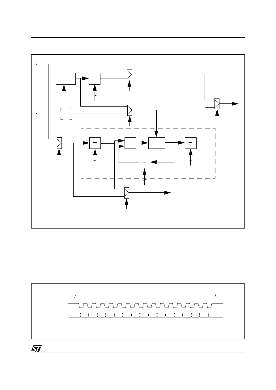
To allow the production of data samples at a desired rate, a digital PLL has been embedded. In this case, the
formulas to be used to calculate the frequency of the signals stated in Figure 1 are:
(Eq. 2.6)
To allow the PLL to operate correctly,
F
ref
must be at least equal to 5 KHz.
(Eq. 2.7)
(Eq. 2.8)
For a better understanding of the IDF, ODF and MF terms, please refer to the PLL registers description.
T
do ub le
1
T s
-------
F
C L K IN
224
-------------------
1
T s
-------
–
--------------------------------------
=
F
C LK IN
224
T s
----------
>
F
C LK IN
N
224
Ts
----------
×
=
F
refd iv
F
ref
IDF
1
+
(
)
-------------------------
=
F
refd iv
F
ref
IDF
1
+
(
)
-------------------------
=
F
d co
F
re fdiv
M F
1
+
(
)
F
ref
M F
1
+
(
)
IDF
1
+
(
)
-------------------------
=
=
F
refdiv
F
dc o
O DF
1
+
(
)
----------------------------
F
ref
M F
1
+
(
)
IDF
1
+
(
)
O DF
1
+
(
)
-----------------------------------------------------
=
=
3/12
AN1515 APPLICATION NOTE
Figure 1. Clock generation scheme
1.2 Serial Interface
The Serial Interface interacts with the outside world with 3 wires: SPE, SPC and SPD. It is used to write the data
into the registers (REGISTERS block) which can also be read.
1.2.1 READ & WRITE REGISTER
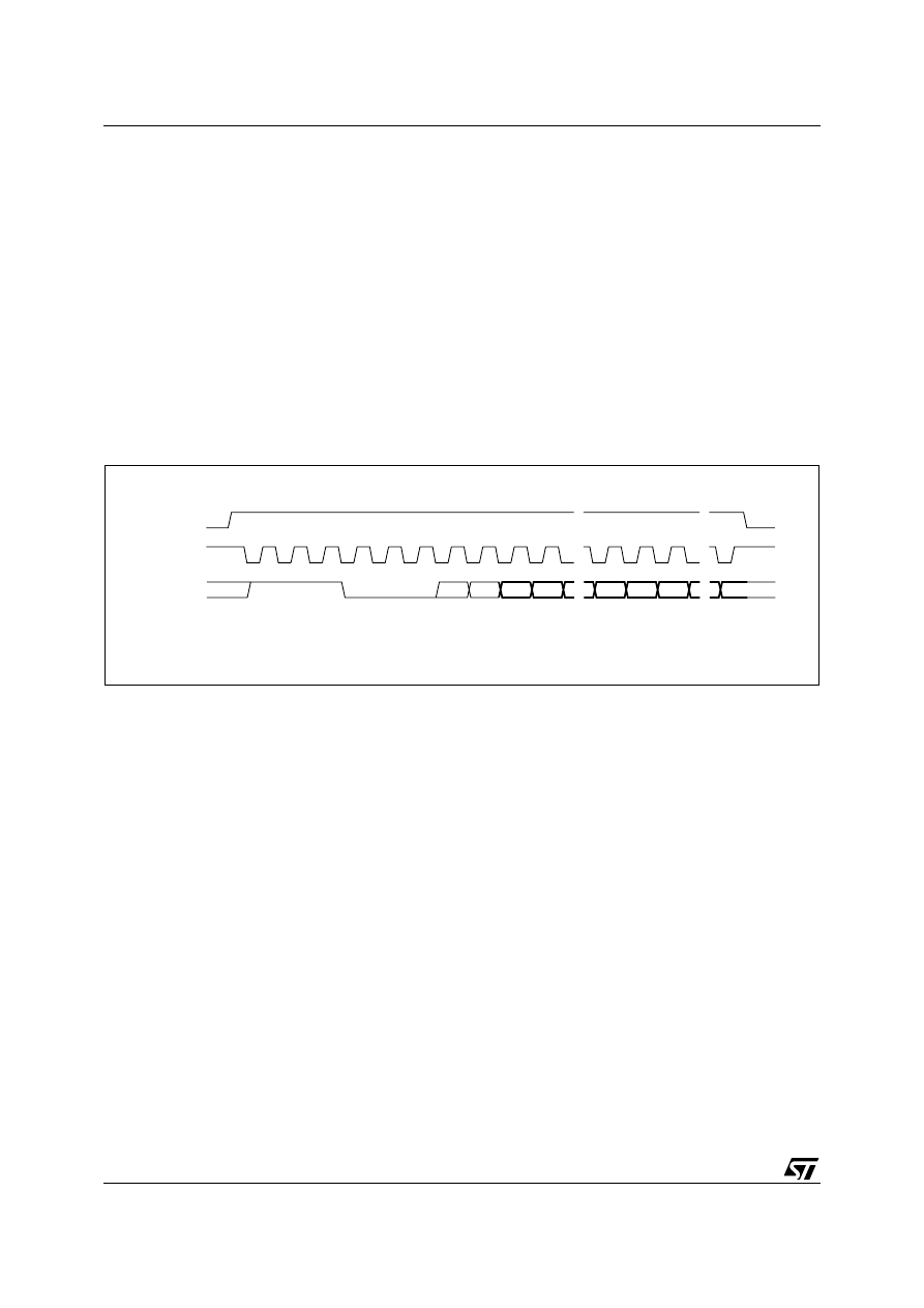
Figure 2. Read & write protocol
OSC
.
.
IOD[3:0]
.
.
IDF[3:0]
x2
PD
DCO
.
.
MF[9:0]
.
.
ODF[1:0]
CS0
0
1
CS0
0
1
CS1
0
1
DSC
Reference signal
pin_CLK
FIFO_Low Read
(from internal logic)
ADPLL
F
osc
F
oscdiv
F
ref
F
refdiv
F
dco
F
osc
DSCR
1
0
PLLT
0
1
SPE
OPDN
Main CK
SPC
SPE
SPD
RW
ID2 ID1 ID0
AD3 AD2 AD1 AD0
D7 D6 D5 D4 D3 D2 D1 D0
AN1515 APPLICATION NOTE
4/12
SPE is the Serial Port Enable. It goes high at the start of the transmission and goes back low at the end. SPC
is the Serial Port Clock. It is stopped high when SPE is low (no transmission). SPD is the Serial Port Data. It is
driven by the falling edge of SPC. It should be captured at the rising edge of SPC.
The Read Register or Write Register command consists of 16 clocks or bits. A bit duration is the time between
two falling edges of SPC. The first bit (bit 0) starts at the first falling edge of SPC after the rising edge of SPE
and the last bit (bit 15) starts at the last falling edge of SPC just before the falling edge of SPE.
bit 0: RW bit. When 0, the data D(7:0) is written into the RAC. When 1, the data D(7:0) from the RAC is read. In
this case, the chip will drive SPD at the start of bit 8.
bit 1-3: chip ID. The chip ID for the RAC is ID(2:0)=110. The LIS1R02 accepts the command only when the ID
is valid (equal to 110).
bit 4-7: address AD(3:0). This is the address field for the registers.
bit 8-15: data D(7:0). This is the data that will be written (read) into (from) the register which address is AD(3:0).
1.2.2 READ FIFO
Figure 3. Read FIFO protocol
The Read FIFO command consists of 24 clocks or bits:
bit 0: READ bit. The value is 1.
bit 1-3: chip ID. ID(2:0)=110.
bit 4-7: FIFO address. The FIFO has four registers grouped into two banks. The first bank consists of the first
and the second register. The first register is the one written first since the last read. The second bank consists
of the third and fourth register.
000x: address for the first bank
001x: address for the second bank
bit 8-23: FIFO data. The RAC puts out first the data of the first register of the bank starting with the MSB.
1.2.3 Notice
The serial interface allows the IC to work with the SPE line tied high.
The clock line has to be normally high (i.e. clock off-state = 1 as depicted in Figure 2.).
If the clock remains high beyond the time out period, the serial interface is reset. This feature allows a IC test to
run at very low frequency using narrow clock pulses. If a packet is not completed correctly, the normal high clock
will generate a port reset, flushing the data.
The timeout period is set to be 280*T
osc
. Thus, supposing to have F
osc
= 70 MHz, the timeout period will be 4
µ
s.
SPC
SPE
SPD
RW
ID2 ID1 ID0
AD3 AD2 AD1 AD0
D7-0 D6-0 ...... D0-0 D7-1 D6-1 ...... D0-1

5/12
AN1515 APPLICATION NOTE
1.3 Registers: array organization
The internal registers are organized as follows:
Table 1. Registers Array
Notes: (*) Value stored inside the embedded FLASH and loaded at boo
Due to the limited number of address bit (4) allowed by the SPI protocol and the high number of registers present
internally to the device, the registers have been spit and grouped into three banks.
To switch between Reg. Bank 1, Reg. Bank 2 and Reg. Bank 3 it is necessary to access the miscellaneous reg.
located @ address 1111.
The registers not loaded at boot can be written also before the boot procedure is completed.
No reading is allowed until the boot is done. The boot procedure takes 1800 clock pulses to be completed.
More information are reported in the paragraphs below.
Address
Reg. Bank 1
Reg. Bank 2
Reg. Bank 3
0000
FIFO_Low
FIFO_Low
FIFO_Low
0001
not used
not used
not used
0010
FIFO_High
FIFO_High
FIFO_High
0011
not used
not used
not used
0100
CTRL_Reg1
CTRL_Reg1
CTRL_Reg1
0101
CTRL_Reg2
CTRL_Reg2
CTRL_Reg2
0110
PLL_PRESC_MULT
FLASH_Reg_1
PLL_COMPARE_REG
0111
PLL_MULT
FLASH_Reg_2
PLL_RST_VALUE_REG
1000
IIR_A0 (*)
GAIN_Low (*)
not used
1001
IIR_A1 (*)
GAIN_High (*)
not used
1010
IIR_A2 (*)
OFFSET_Low (*)
not used
1011
IIR_B1 (*)
OFFSET_High (*)
not used
1100
IIR_B2 (*)
CURR_BANDGAP (*)
not used
1101
IIR_SIGN_BIT (*)
BAND_CSACT_REG (*)
not used
1110
DSC_Reg
CS_TRIM (*)
not used
1111
MISC_Reg
MISC_Reg
MISC_Reg
AN1515 APPLICATION NOTE
6/12
1.4 Registers Description
The only registers that can be modified by the user are described in the section that follows.
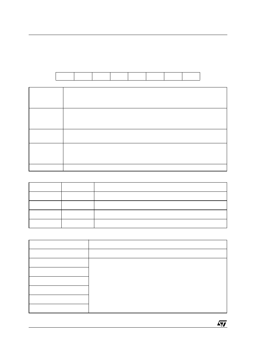
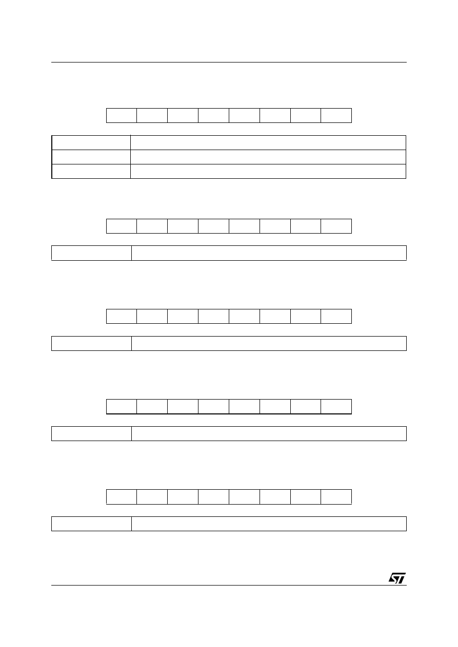
1.4.1 CONTROL_REG (0100)
Table 2. Clock Source Selection
Table 3. Control Bit
PDN
IEN
CS1
CS0
OPDN
B2
B1
B0
PDN
Chip power down
0: chip on (default value)
1: chip in power down mode
IEN
Interrupt enable:
0: interrupt signal available to the external
1: pad in high Z (default value);
CS1-CS0
Clock Source Selection. For more information look at paragraph “clock scheme”
By default are set to 00
OPDN
Oscillator Power Down:
0: oscillator toggling (default value);
1: oscillator turned off
B2-B0
Control bit definition
CS1
CS0
Clock Source
0
0
Clock from CLK pin
0
1
Internal Oscillator
1
0
Clock from PLL locking on CLK pin
1
1
Clock from PLL locking on FIFO_low reg. reading
B2-B0
Mode selection
000
Normal mode (default)
001
Not allowed
010
011
100
101
11X
7/12
AN1515 APPLICATION NOTE
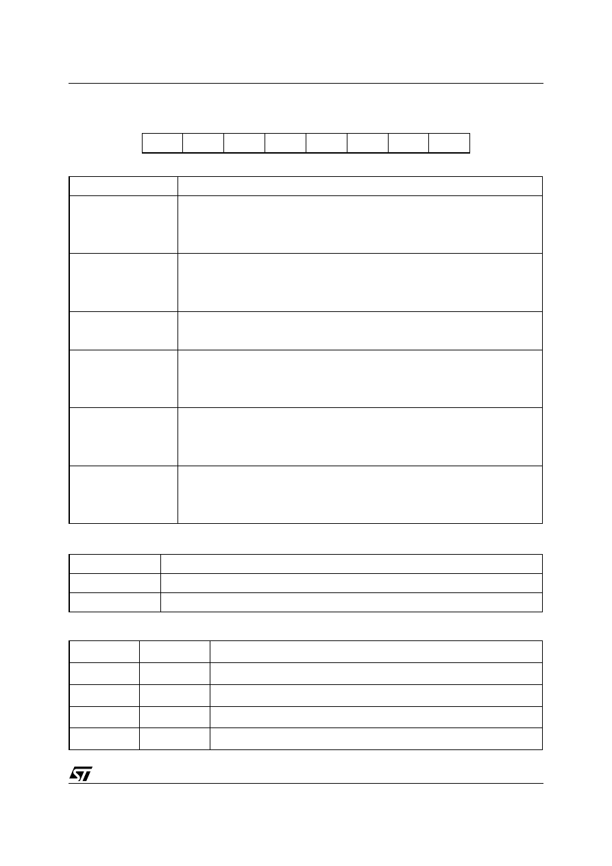
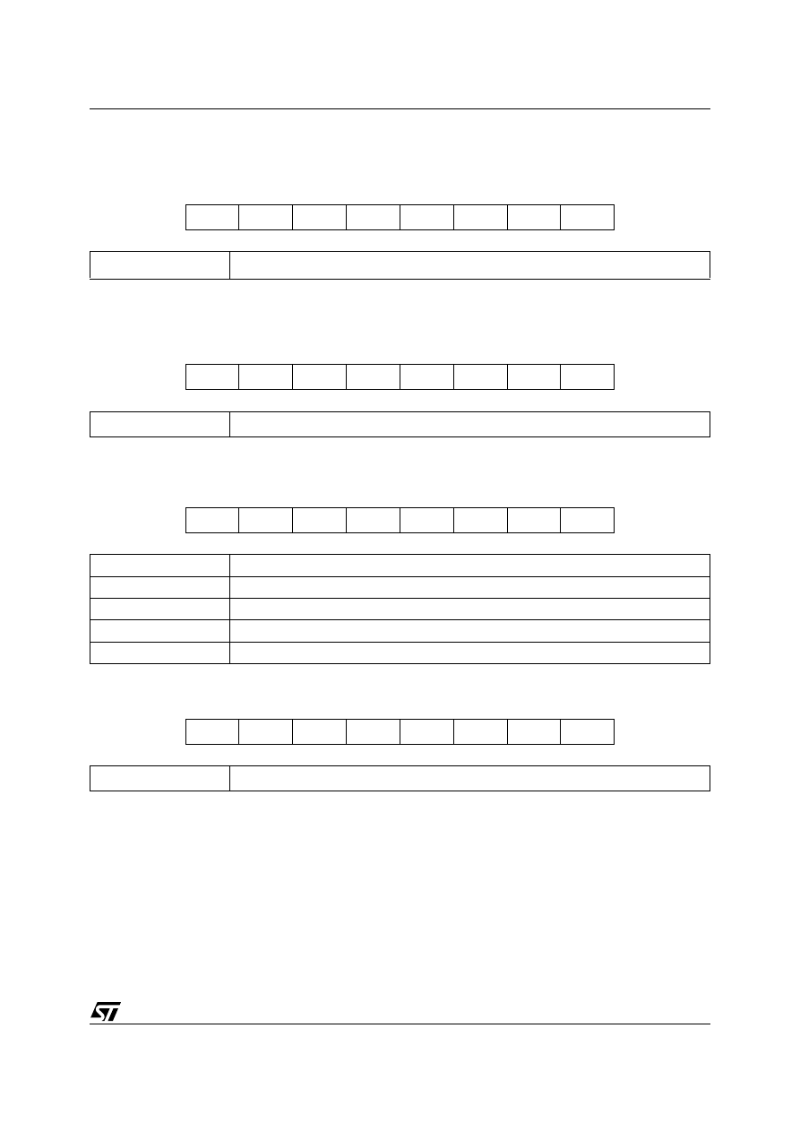
1.4.2 CONTROL_REG2 (0101)
Table 4. DSC Reference signal selection
Table 5. Clock Source Selection
DSCR
DSC
CEN
OWL1
OWL0
IFB
DF
SO
DSCR
Delayed Synchronous Conversion Reference. By default is set to 0.
DSC
Delayed Synchronous Conversion enable
0: Delayed Synchronous Conversion disabled
1: Delayed Synchronous Conversion enabled (default value)
CEN
Clip Enable on the Offset and Gain adjustment unit
0: Clip disabled
1: Clip enabled (default value)
OWL1-OWL0
Output Word Length selection
See table below.
IFB
IIR Filter Bypass
0: IIR filter on (default value)
1: IIR filter bypassed
DF
Decimation Factor selection (normal mode only; no DSC)
0: decimate by 16
1: decimate by 32 (default value)
SO
Sinc Order selection
0: 2nd order
1: 3rd order (default value)
DSCR
Delayed Synchronous Conversion Reference
0
pin_CLK or FIFO_read_low, depending on CS0 value
1
Input clock divider output
OWL1
OWL0
Output Word Length
0
0
8 bit (default mode)
0
1
16 bit
1
0
32 bit
1
1
32 bit
AN1515 APPLICATION NOTE
8/12
1.4.3 PLL_PRESC_MULT (0110 -Reg. Bank1-)
This register contains the value used by the PLL prescaler to divide the input reference clock and the most sig-
nificant bit of the PLL multiplication factor. Both the parameters are expressed in unsigned binary format.
1.4.4 PLL_MULT (0111 -Reg. Bank 1-)
This register contains the value used by the PLL prescaler to divide the input reference clock and the most sig-
nificant bit of the PLL multiplication factor. Both the parameters are expressed in unsigned binary format.
1.4.5 IIR_A0 (1000 -Reg. Bank 1-)
Contains the LSB of the coefficient A0 used in the IIR filter. The sign bit is A0_8 and is stored in register
IIR_SIGN_BIT (address 1101 -Reg. Bank 1-). The complete coefficient A0_8-A0_0 is expressed in two’s com-
plement format.
1.4.6 IIR_A1 (1001 -Reg. Bank 1-)
Contains the LSB of the coefficient A1 used in the IIR filter. The sign bit is A1_8 and is stored in register
IIR_SIGN_BIT (address 1101 -Reg. Bank 1-). The complete coefficient A1_8-A1_0 is expressed in two’s com-
plement format
1.4.7 IIR_A2 (1010 -Reg. Bank 1-)
Contains the LSB of the coefficient A2 used in the IIR filter. The sign bit is A2_8 and is stored in register
IIR_SIGN_BIT (address 1101 -Reg. Bank 1-). The complete coefficient A2_8-A2_0 is expressed in two’s com-
plement format.
IDF3
IDF2
IDF1
IDF0
ODF1
ODF0
MF9
MF8
IDF3-IDF0
PLL Input Division Factor (Default: 0000)
ODF1-ODF0
PLL Output Division Factor (Default: 00)
MF9-MF8
PLL Multiplication Factors MSB (Default: 00)
MF7
MF6
MF5
MF4
MF3
MF2
MF1
MF0
MF7-MF0
PLL Multiplication Factors LSB (Default: 11011111)
A0_7
A0_6
A0_5
A0_4
A0_3
A0_2
A0_1
A0_0
A0_7-A0_0
LSBs of the coefficient A1 used inside the IIR Filter (LSB)
A1_7
A1_6
A1_5
A1_4
A1_3
A1_2
A1_1
A1_0
A1_7-A1_0
LSBs of the coefficient A1 used inside the IIR Filter (LSB)
A2_7
A2_6
A2_5
A2_4
A2_3
A2_2
A2_1
A2_0
A2_7-A2_0
LSBs of the coefficient A2 used inside the IIR Filter (LSB
9/12
AN1515 APPLICATION NOTE
1.4.8 IIR_B1 (1011 -Reg. Bank 1-)
Contains the LSB of the coefficient B1 used in the IIR filter. The sign bit is B1_8 and is stored in register
IIR_SIGN_BIT (address 1101 -Reg. Bank 1-). The complete coefficient B1_8-B1_0 is expressed in two’s com-
plement format.
1.4.9 IR_B2 (1100 -Reg. Bank 1-)
Contains the LSB of the coefficient B2 used in the IIR filter. The sign bit is B2_8 and is stored in register
IIR_SIGN_BIT (address 1101 -Reg. Bank 1-). The complete coefficient B2_8-B2_0 is expressed in two’s com-
plement format.
1.4.10IIR_SIGN_BIT (1101 -Reg. Bank 1-)
Contains the sign bit for the coefficients used inside the IIR filter. All the coefficients are expressed in two’s com-
plement format.
1.4.11DSC_Reg (1110 -Reg. Bank 1-)
Contains the threshold value used to trigger the decimation when in Delay Synchronous Conversion mode.
B1_7
B1_6
B1_5
B1_4
B1_3
B1_2
B1_1
B1_0
B1_7-B1_0
LSBs of the coefficient B2 used inside the IIR Filter (LSB)
B2_7
B2_6
B2_5
B2_4
B2_3
B2_2
B2_1
B2_0
B2_7-B2_0
LSBs of the coefficient B2 used inside the IIR Filter (LSB)
X
B2_8
B1_8
X
X
A2_8
A1_8
A0_8
B2_8
Sign bit for coefficient B2
B1_8
Sign bit for coefficient B1
A2_8
Sign bit for coefficient A2
A1_8
Sign bit for coefficient A1
A0_8
Sign bit for coefficient A0
DT7
DT6
DT5
DT4
DT3
DT2
DT1
DT0
DT7-DT0
DSC Threshold
AN1515 APPLICATION NOTE
10/12
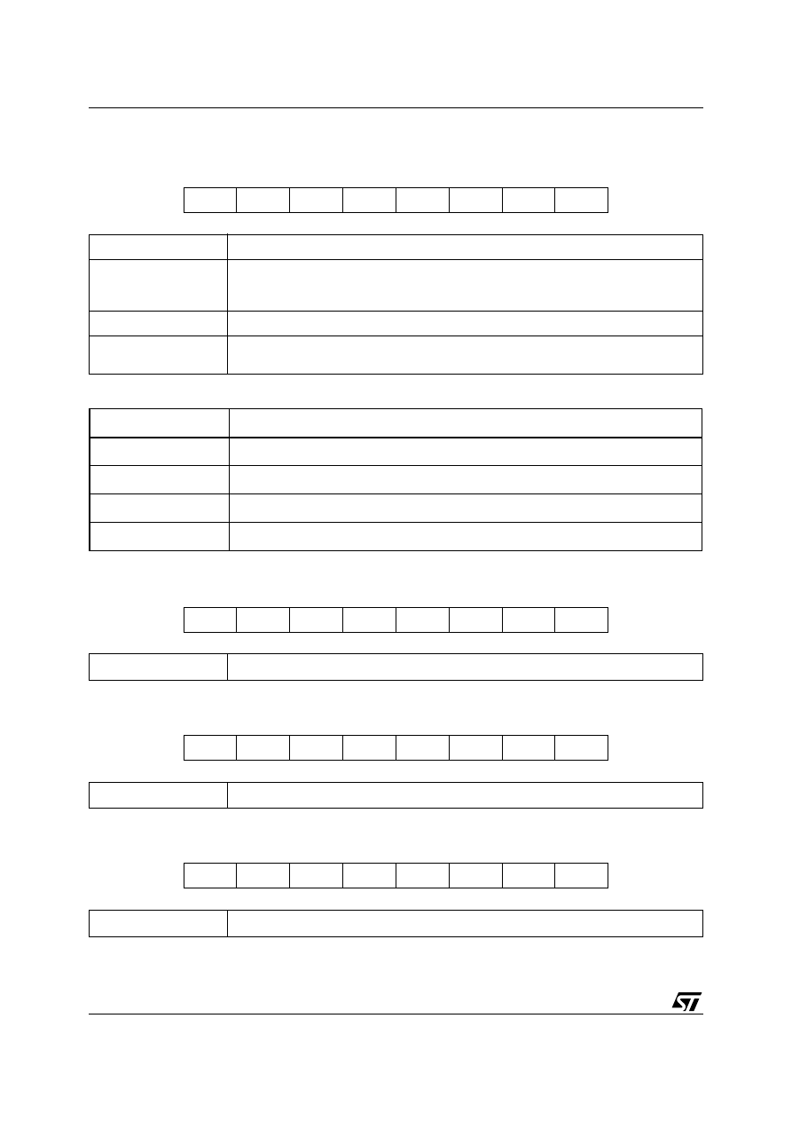
1.4.12MISC_Reg (1111)
This register is used to switch between registers bank1 and registers bank2 and to select the division factor of
the divider acting on the internal oscillator. It also allows to force a SW reset on the device.
Table 6. Registers Bank selection
1.4.13GAIN_LSB (1000 -Reg. Bank 2-)
1.4.14GAIN_MSB (1001 -Reg. Bank 2-)
1.4.15OFFSET_LSB (1010 -Reg. Bank 2-)
RES
PLLT
IOD3
IOD2
IOD1
IOD0
BS1
BS0
RES
Force SW reset on the device (Active High)
PLLT
PLL Test using an external clock source
(0: PLL clock from internal OSCillator (default value);
1: clock from SPE pad when t8 is high)
IOD3-IOD0
Internal Oscillator Divider (Set to 1000 by default)
BS1-BS0
Registers Bank Select
At reset BS1-BS0=00 making Reg. Bank 1 accessible by default
BS1-BS0
Registers Bank Selection
00
Bank 1
01
Bank 2
10
Bank 3
11
not used
GL7
GL6
GL5
GL4
GL3
GL2
GL1
GL0
GL7-GL0
8 LSB of the digital gain block
GH7
GH6
GH5
GH4
GH3
GH2
GH1
GH0
GH7-GH0
8 MSB of the digital gain block
OL7
OL6
OL5
OL4
OL3
OL2
OL1
OL0
OL7-OL0
8 LSB of the digital offset correction value

11/12
AN1515 APPLICATION NOTE
1.4.16OFFSET_MSB (1011 -Reg. Bank 2-)
1.5 Device initialization
Before using the device, the user must disable the Delayed Synchronous Conversion Option (bit DSC of
CTRL_REG2) and set the Sinc Order (bit SO of CTRL_REG2) to 2.
This is achieved by writing 0010 0010 inside the CTRL_REG2 register.
1.6 Circuit Board and Layout Considerations
In order to avoid, in the analog section, any kind of disturbances coming from the digital section, the 5V supply
and the ground are split between analog lines and digital lines. For this reason the VDD_DIGITAL 5V supply
and the GND_DIGITAL ground have been added. The two 5V supply lines must be powered up and down si-
multaneously (a maximum 0.3V difference between them is allowed. The two 5V supply lines and the two
ground lines could be derived from a single low-voltage supply and a single ground but must be connected to
the chip using two separate decoupling capacitors.
The LIS1R02 IC by default expects a master clock coming into the CLK_IN pin. This master clock frequency
must be lower than 6MHz. A ground plane must be located under the chip to help prevent any disturbance to
the LIS1R02 sensor.
Each of the two power supplies requires decoupling capacitors. It is recommended that each VDD pin (analog
and digital) have a 0.22
µ
F as near as possible to the chip pin. A 22
µ
F electrolytic capacitor on the supply line
is also advised. As close as possible to the REF_CAP pin (pin 8), two decoupling capacitors must be placed. A
0.22
µ
F electrolytic and a 220pF ceramic or polyester are strongly recommended.
Due to the high sensitivity of this device maximum care must be taken during board layout to avoid any kind of
coupling between CLK_IN, power supplies and grounds tracks. In order to avoid any performance loss, the
REF_CAP pin and the board trace that connects it must be far from any kind of noisy signal (i.e. CLK_IN).
OH7
OH6
OH5
OH4
OH3
OH2
OH1
OH0
OH7-OH0
8 MSB of the digital offset correction value

Information furnished is believed to be accurate and reliable. However, STMicroelectronics assumes no responsibility for the consequences
of use of such information nor for any infringement of patents or other rights of third parties which may result from its use. No license is granted
by implication or otherwise under any patent or patent rights of STMicroelectronics. Specifications mentioned in this publication are subject
to change without notice. This publication supersedes and replaces all information previously supplied. STMicroelectronics products are not
authorized for use as critical components in life support devices or systems without express written approval of STMicroelectronics.
The ST logo is a registered trademark of STMicroelectronics
2002 STMicroelectronics - All Rights Reserved
STMicroelectronics GROUP OF COMPANIES
Australia - Brazil - Canada - China - Finland - France - Germany - Hong Kong - India - Israel - Italy - Japan -Malaysia - Malta - Morocco -
Singapore - Spain - Sweden - Switzerland - United Kingdom - United States.
http://www.st.com
12/12
AN1515 APPLICATION NOTE
Wyszukiwarka
Podobne podstrony:
Ch07 Digital Outputs
3axis Digital Accelerometer ST AIS326DQ id 36590
3axis Digital Accelerometer ADXL345
Principles of Sigma Delta Conversion for Analog to Digital Converters
Page153 Model 2491 2492 2493 Digital Switchboard meter c
output
Digital ECU Tuner III Manual
przekaz digitalny
Ebook Spraw 2 Netpress Digital
więcej podobnych podstron