Lab 6.2.12a Configure Remote Access Using Cisco Easy VPN
Objective
In this lab, the students will complete the following tasks:
• Enable policy lookup via authentication, authorization, and accounting (AAA)
• Define group policy information for mode configuration push
• Configure and Verify the IPSec Transforms and Crypto Maps
• Install and configure the Cisco VPN Client 4.0 or later
• Connect to the corporate Intranet using the Cisco VPN Client
Scenario
A network administrator needs secure management access to the perimeter router and other critical
devices on the internal network. In a small company, the budget may not allow for a dedicated VPN
Concentrator. Fortunately, the IOS Firewall router can be configured as an Easy VPN Remote
server, allowing a Cisco VPN software client to connect. Once connected, the remote user can
access internal IP based resources.
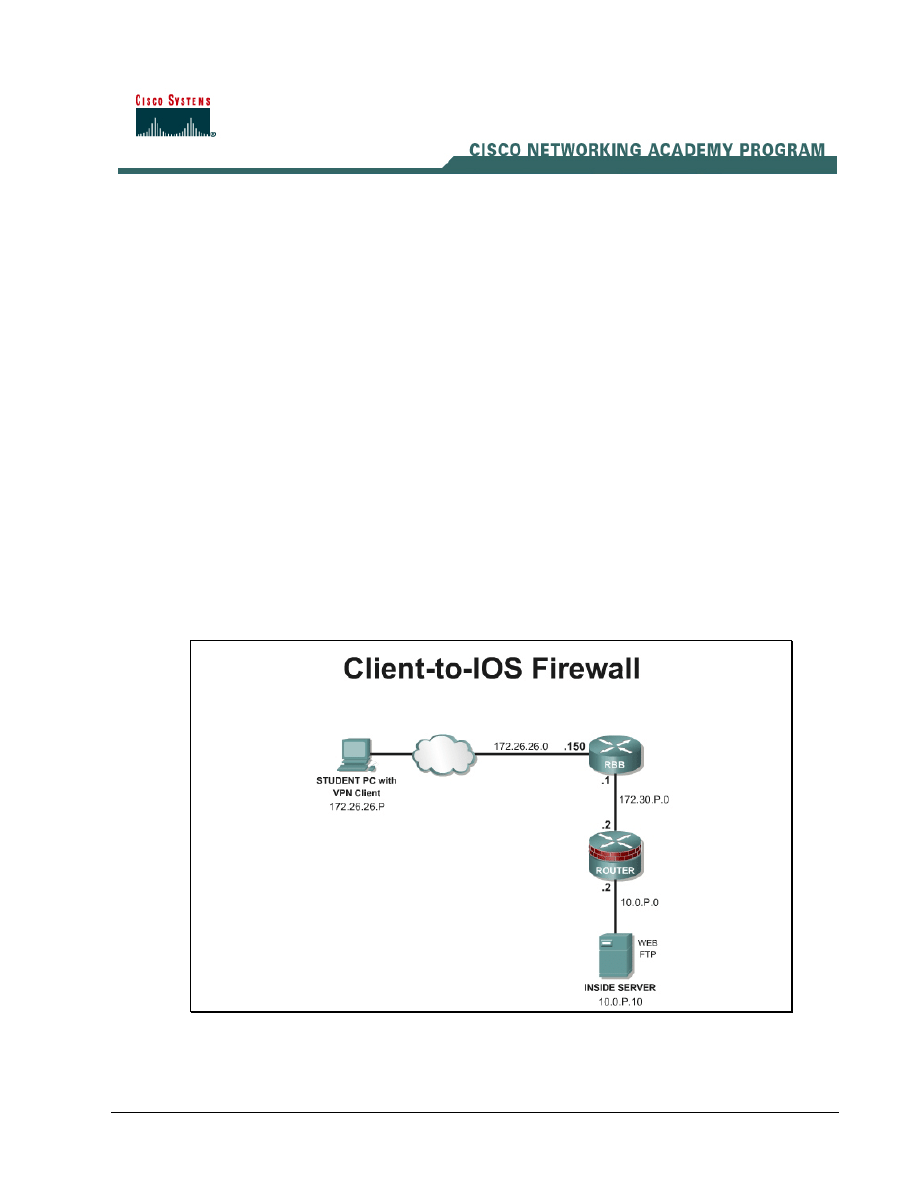
Topology
This figure illustrates the lab network environment.
Preparation
1 - 9
Network Security 2 v2.0 – Lab 6.2.12a
Copyright
© 2005, Cisco Systems, Inc.

Begin with the topology above and verify the starting configuration on the pod routers. Access the
perimeter router console port using the terminal emulator on the Student PC. If desired, save the
router configuration to a text file for later analysis. Refer back to the Student Lab Orientation if more
help is needed.
Before beginning this lab exercise, it is imperative to change the static IP address of the Student PC
to 172.26.26.P 255.255.255.0 (where P =pod number) with a default gateway of 172.26.26.150.
Also, the Student PC must be physically connected to a switch port on VLAN 1.
Tools and resources
In order to complete the lab, the following is required:
• Standard Client-to-IOS Firewall lab topology
• Console cable
• HyperTerminal
• Cisco VPN Client 4.6 or later
Additional materials
Further information about the objectives covered in this lab can be found at the following websites:
http://www.cisco.com/en/US/products/sw/iosswrel/ps1839/products_feature_guide09186a0080087d1
e.html
Command list
In this lab exercise, the following commands will be used. Refer to this list if assistance or help is
needed during the lab exercise.
Command
Description
aaa authentication
Set parameters that restrict a user's network access
aaa new-model
Enables AAA.
crypto isakmp client
configuration group {group-
name | default}
Specifies which group's policy profile will be defined
and enters Internet Security Association Key
Management Protocol (ISAKMP) group configuration
mode.
If no specific group matches and a default group is
defined, users will automatically be given the default
group's policy.
crypto map map-name client
authentication list list-name
Enforces Xauth. The list-name argument is used to
determine the appropriate username and password
storage location (local or RADIUS) as defined in the
aaa authentication login
command.
2 - 9
Network Security 2 v2.0 – Lab 6.2.12a
Copyright
© 2005, Cisco Systems, Inc.

Command
Description
crypto map map-name client
configuration address
[initiate | respond]
Configures the router to initiate or reply to Mode
Configuration requests.
Note that the Cisco clients require the respond
keyword to be used. However, if the Cisco Secure
VPN Client 1.x is used, the initiate keyword must
be used. The initiate and respond keywords
may be used simultaneously.
crypto map map-name isakmp
authorization list list-name
Enables IKE querying for group policy when
requested by the client. The list-name argument is
used by AAA to determine which storage source is
used to find the policy (local or RADIUS) as defined
in the aaa authorization network command.
ip local pool {default | pool-
name low-ip-address [high-ip-
address]}
Configures a group of local IP address pools
username name password
encryption-type encrypted-
password
Defines local users for Xauth if RADIUS or TACACS+
is not used.
Use this command only if no external validation
repository will be used.
Step 1 Enable Policy Lookup using Local AAA
To enable policy lookup using local AAA, complete the following commands for the perimeter router
beginning in global configuration mode:
a. Enable
AAA:
RouterP(config)#aaa new-model
b. Set AAA authentication at login. Note that this command must be enabled to enforce Xauth.
RouterP(config)#aaa authentication login VPNAUTHEN local
c. Set AAA authorization at login.
RouterP(config)# aaa authorization network VPNAUTHOR local
d. Define local users:
RouterP(config)#username vpnstudent password cisco
Step 2 Define Group Policy Information for Mode Configuration Push
Define the policy attributes that are pushed to the VPN Client via mode configuration. Use the
following commands beginning in global configuration mode:
a. Configure a local pool of IP addresses to be used when a remote peer connects to a point-to-
point interface.
RouterP(config)#ip local pool IPPOOL 11.0.P.20 11.0.P.30
(where P = pod number)
b. Create the ISAKMP policy:
RouterP(config)# crypto isakmp policy 3
RouterP(config-isakmp)# encryption des
3 - 9
Network Security 2 v2.0 – Lab 6.2.12a
Copyright
© 2005, Cisco Systems, Inc.

RouterP(config-isakmp)# hash md5
RouterP(config-isakmp)# authentication pre-share
RouterP(config-isakmp)# group 2
RouterP(config-isakmp)# exit
RouterP(config)#
c. Specify which group policy profile will be defined and enter ISAKMP group configuration mode. If
no specific group matches and a default group is defined, users will automatically be given the
default group policy. For this exercise, use a group name of “SALES”.
RouterP(config)#crypto isakmp client configuration group SALES
d. Specify the IKE pre-shared key for group policy attribute definition. Note that this command must
be enabled if the VPN Client identifies itself with a pre-shared key. For this exercise, use a key of
“cisco123”.
RouterP(isakmp-group)#key cisco123
e. Select a local IP address pool. Note that this command must refer to a valid local IP local
address pool or the VPN Client connection will fail. Use the “IPPOOL” pool name.
RouterP(isakmp-group)#pool IPPOOL
f.
Define a domain name:
RouterP(isakmp-group)#domain cisco.com
RouterP(isakmp-group)#exit
g. Examine the crypto policy suite.
RouterP# show crypto isakmp policy
Step 3 Configure and Verify the IPSec Transforms and Crypto Maps
a. Create the transform set to be used with the dynamic crypto map. Name the transform set
MYSET. Specify triple-DES for encryptions in the ESP and MD5 HMAC authentication in the
ESP.
RouterP(config)# crypto ipsec transform-set MYSET esp-des esp-md5-
hmac
RouterP(cfg-crypto-trans)# exit
b. Create the dynamic crypto map:
RouterP(config)# crypto dynamic-map DYNMAP 10
RouterP(config-crypto-map)# set transform-set MYSET
RouterP(config-crypto-map)# reverse-route
RouterP(config-crypto-map)# exit
c. Configure the router to initiate or reply to mode configuration requests. Note that VPN Clients
require the respond keyword to be used.
RouterP(config)#crypto map CLIENTMAP client configuration address
respond
d. Enable IKE querying for group policy when requested by the VPN Client. The list-name
argument is used by AAA to determine which storage is used to find the policy, local or RADIUS,
as defined in the aaa authorization network command.
RouterP(config)#crypto map CLIENTMAP isakmp authorization list
VPNAUTHOR
4 - 9
Network Security 2 v2.0 – Lab 6.2.12a
Copyright
© 2005, Cisco Systems, Inc.

e. Enforce Xauth. The list-name argument is used to determine the appropriate username and
password storage location, local or RADIUS, as defined in the aaa authentication login
command.
RouterP(config)#crypto map CLIENTMAP client authentication list
VPNAUTHEN
f.
Assign the dynamic crypto map to CLIENTMAP:
RouterP(config)# crypto map CLIENTMAP 10 ipsec-isakmp dynamic DYNMAP
g. Assign the crypto map to the outside interface:
RouterP(config)# interface fastEthernet 0/1
RouterP(config-if)# crypto map CLIENTMAP
RouterP(config-if)# exit
h. To verify the configurations for this feature, use the following command in EXEC mode to view
the crypto map configuration:
RouterP#show crypto map {interface interface | tag map-name}
i.
To verify the configurations for this feature, use the following command in EXEC mode to view
the transform set:
RouterP# show crypto ipsec transform-set
Step 4 Install the Cisco VPN Client 4.0
Complete the following steps to install the Cisco VPN Client version 4.0 or later on the Student PC:
a. Open the VPN Client desktop folder.
b. Locate and run the Cisco VPN Client setup.exe executable. If this is the first time the VPN Client
is installed, a window opens and displays the following message: Do you want the installer to
disable the IPSec Policy Agent?
c. Click Yes to disable the IPSec policy agent. The Welcome window opens.
d. Read
the Welcome window and click Next. The License Agreement window opens.
e. Read the license agreement and click Yes. The Choose Destination Location window opens.
f. Click
Next. The Select Program Folder window opens.
g. Accept the defaults by clicking Next. The Start Copying Files window opens.
The files are copied to the hard disk drive of the PC and the InstallShield Wizard Complete
window opens.
h. Select
Yes, I want to restart my computer now and click Finish. The PC restarts. This
completes the installation of the Cisco VPN Client (Software Client).
Step 5 Create a New Connection Entry
Complete the following steps to create a new VPN connection entry:
a. Choose
Start > Programs > Cisco Systems VPN Client > VPN Client. The Cisco Systems
VPN Client window opens.
5 - 9
Network Security 2 v2.0 – Lab 6.2.12a
Copyright
© 2005, Cisco Systems, Inc.
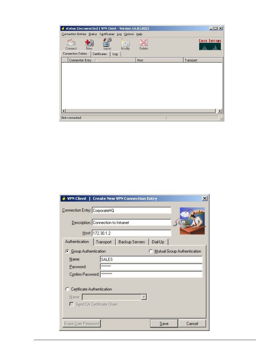
b. Click
the
New button. The Create New VPN Connection Entry window opens.
c. Enter
CorporateHQ in the Connection Entry field.
d. Enter a public interface IP address of 172.30.P.2 in the Host field.
(where P = pod number)
e. Click on the Group Authentication radio button and complete the following substeps. The
following entries are always case sensitive.
• Enter a group name, SALES.
• Enter the group password, cisco123.
• Confirm the password, cisco123.
6 - 9
Network Security 2 v2.0 – Lab 6.2.12a
Copyright
© 2005, Cisco Systems, Inc.
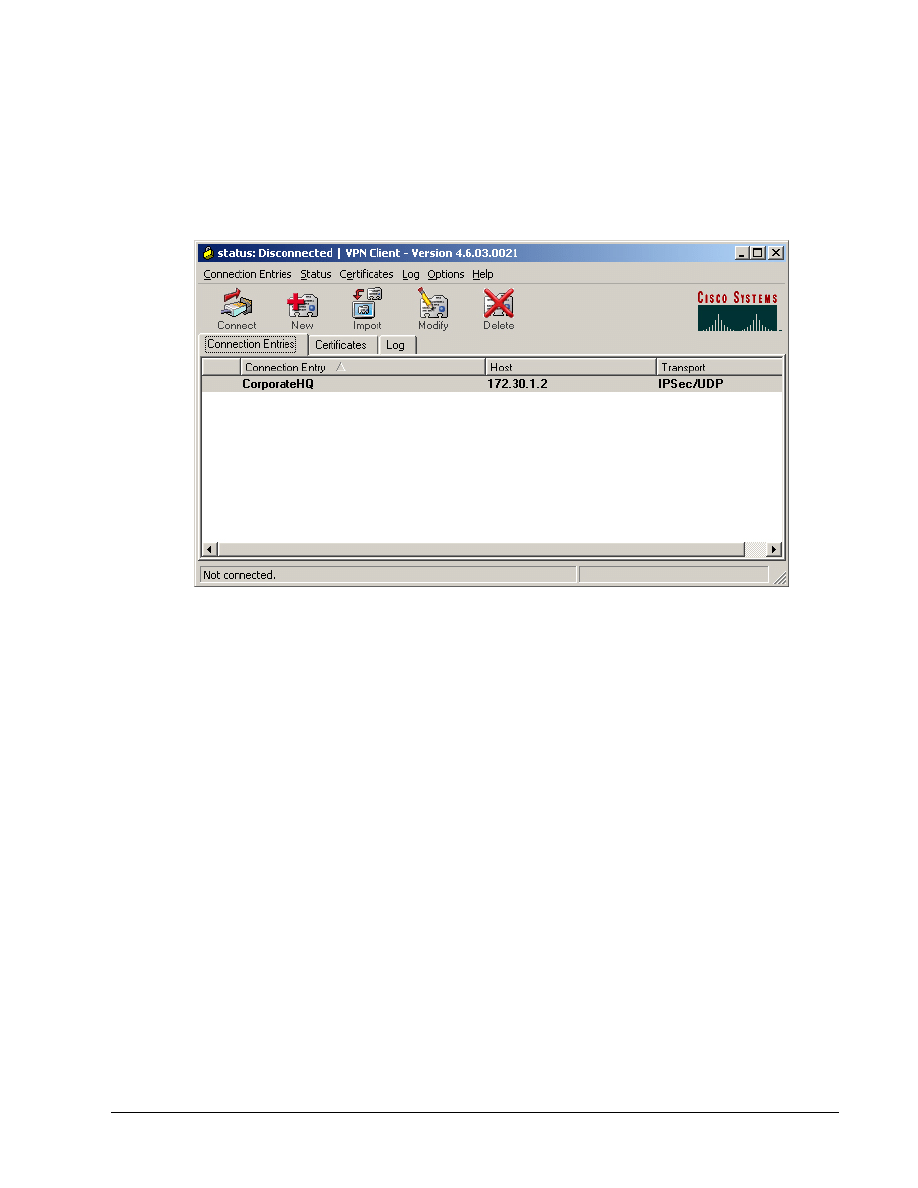
f. Click
the
Save button and leave the Cisco Systems VPN Client window open.
The network parameters for the VPN Client have been configured and a new VPN private
networking connection entry has been created successfully.
Step 6 Launch the Cisco VPN Client
Complete the following steps to launch the Cisco VPN client on the PC:
a. Verify that the connection entry is CorporateHQ.
b. Verify that the IP address of remote server is set to the perimeter router public interface IP
address of 172.30.P.2.
(where P = pod number)
c. Click
Connect. The User Authentication window opens and several messages flash by quickly.
Complete the following substeps:
i.
When prompted for a username, enter vpnstudent.
ii. When prompted to enter a password, enter cisco.
iii. Click
OK.
The Authentication window disappears and a VPN lock icon appears in the system tray. The
VPN Client has been successfully launched.
d. On the router console, the following message should appear.
Router1#
03:12:00: %CRYPTO-5-SESSION_STATUS: Crypto tunnel is UP . Peer
172.26.26.1:500 Id: SALES
Step 7 Monitor the Cisco VPN Client
Complete the following steps to monitor the Cisco VPN client connection on the PC:
a. Go
to
Start>Run on a Win2k or XP computer.
b. Type
in
cmd
c. A command prompt will appear. Check the interface configuration using the command.
C:\> ipconfig
7 - 9
Network Security 2 v2.0 – Lab 6.2.12a
Copyright
© 2005, Cisco Systems, Inc.
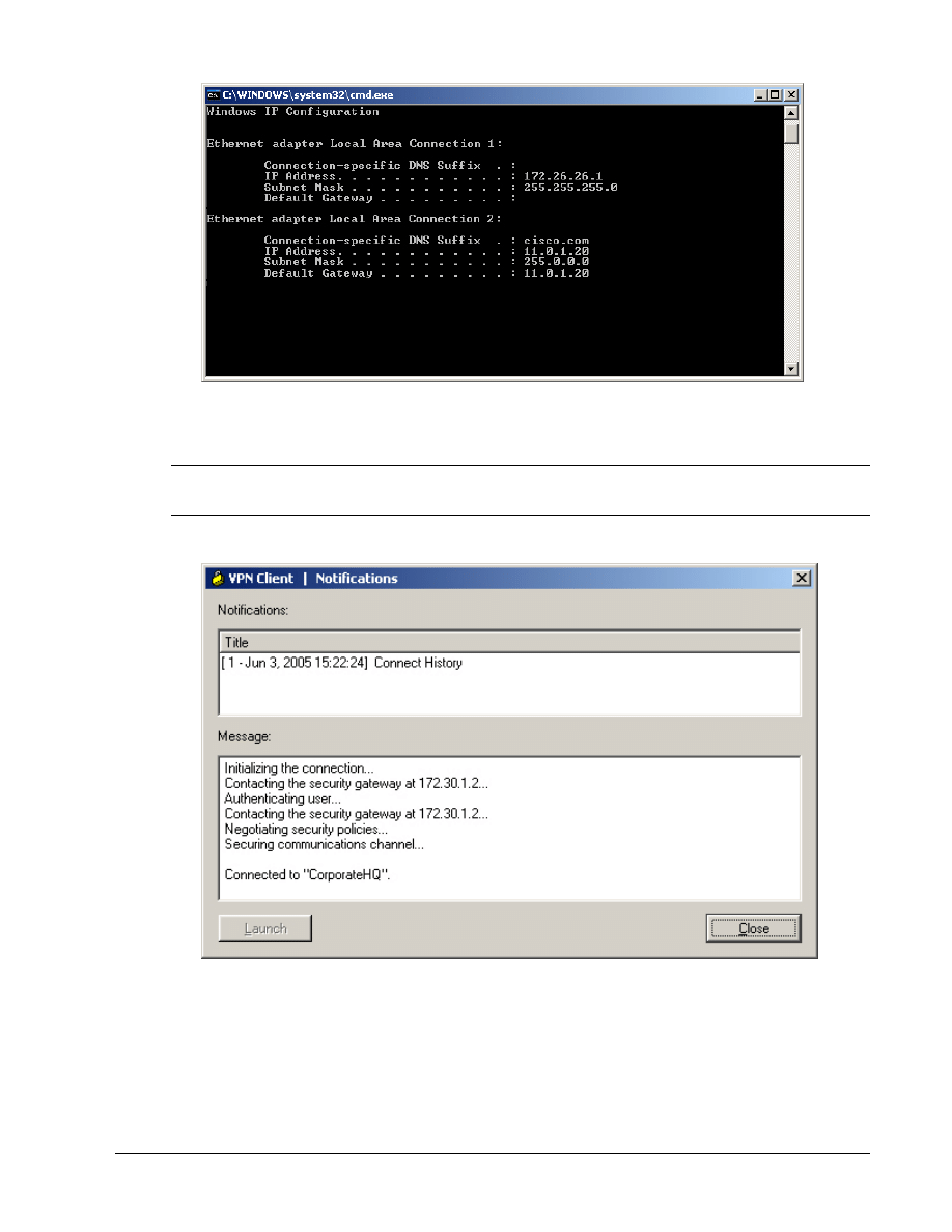
Notice the two Local Area Connection addresses. One is the physical interface, the other is the
virtual interface created by the Cisco VPN client. The virtual interface allows for greater application
support.
Note
This figure shows the results with VPN client version 4.6. The virtual interface is not available previous
to 4.0.
d. Right click on the lock icon located in the system tray and left click on Notifications.
e. This will provide the connection history. Click on the Close button when finished.
f.
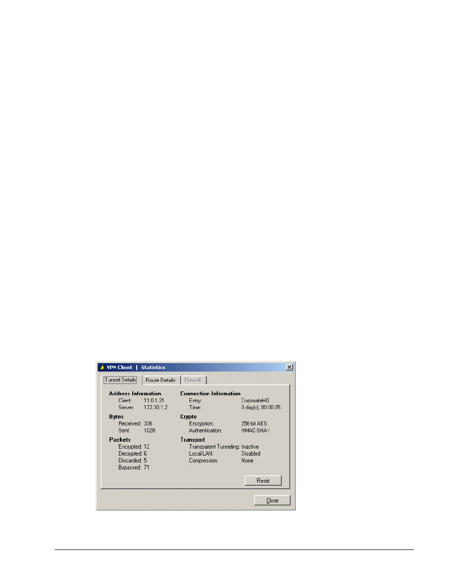
Next, right click on the lock icon located in the system tray and left click on Statistics
g. In the Tunnel Details tab, verify the Address Information. The IP address should be in the range
of 11.0.P.20 – 30. The Server address should be 172.30.P.2
h. Verify the encryption and authentication protocols.
i.
To get a clear picture of the traffic, click on the Reset button to reset the counters to zero.
j.
On the Student PC, open a web browser and connect to the inside interface of the router
8 - 9
Network Security 2 v2.0 – Lab 6.2.12a
Copyright
© 2005, Cisco Systems, Inc.
http://10.0.P.2
k. On the Student PC, open a web browser and connect to the Inside server
http://10.0.P.10
l.
When finished, right click on the lock and left click Disconnect.
m. On the router console, the following message should appear.
03:20:36: %CRYPTO-5-SESSION_STATUS: Crypto tunnel is DOWN. Peer
172.26.26.223:500 Id: SALES
n. Display the current state of the IPSec SAs. The IPSec SAs may have been previously
established by routing traffic. The following example shows initialized IPSec SAs before
encryption traffic:
RouterP# show crypto isakmp sa
RouterP# show crypto ipsec sa
Step 8 Modify the IPSec Transforms
Company XYZ has decided to strengthen the VPN encryption.
a. Create the transform set to be used with the dynamic crypto map. Name the transform set
“MYSET”. Specify AES 256 for encryptions and SHA HMAC authentication.
RouterP(config)# no crypto ipsec transform-set MYSET esp-des esp-
md5-hmac
RouterP(config)# crypto ipsec transform-set MYSET esp-aes 256 esp-
sha-hmac
RouterP(cfg-crypto-trans)# exit
b. Open the VPN client and click Connect. The User Authentication window opens and several
messages flash by quickly. Complete the following substeps:
i.
When prompted for a username, enter vpnstudent.
ii. When prompted to enter a password, enter cisco.
iii. Click
OK.
c. Open the Statistics and verify the new encryption and authentication.
9 - 9
Network Security 2 v2.0 – Lab 6.2.12a
Copyright
© 2005, Cisco Systems, Inc.
Wyszukiwarka
Podobne podstrony:
NS2 lab 6 2 12b en Configure Cisco Easy VPN Server with NAT
NS1 lab 6 1 3 en Configure Local AAA on Cisco Router
NS1 lab 8 3 13 en Configure Cisco IOS Firewall CBAC
NS2 lab 4 4 7 en Configure Cisco IOS IPSec using Pre Shared Keys
NS2 lab 4 4 7 en Configure Cisco IOS IPSec using Pre Shared Keys
NS1 lab 10 2 4 en Mitigate Layer 2 Attacks
LAB EL EN ZAGADNIENIA
Lab ME En spraw strona tytulowa 0 2010 2011, POZOSTAŁE, ELEKTR✦✦✦ (pochodne z nazwy), SEMESTR III, M
LAB EL EN PC schematy
MS Routing & Remote Access
CCNP3 lab 6 2 opt en
CCNP2 lab 5 6c en
CCNP4 lab 6 1b en
CCNP4 lab 6 2b en
więcej podobnych podstron