Lab 6.2.12b Configure Cisco Easy VPN Server with NAT
Objective
In this lab, the students will complete the following tasks:
• Verify Easy VPN Server configuration
• Configure and Modify PAT using CLI
• Configure and Modify PAT using SDM
• Test remote connectivity
Scenario
The Cinko Company opened a new office in China and wants to allow Account Mangers to connect
to the internal web and email servers. A DSL line with one static IP address has recently been
installed. The Remote access VPN must be configured to work with PAT. The local IT manager has
already configured the router with a VPN configuration used at the Headquarters. The VPN client
will connect to the router, but connectivity to the inside devices on the network is not possible at this
time.
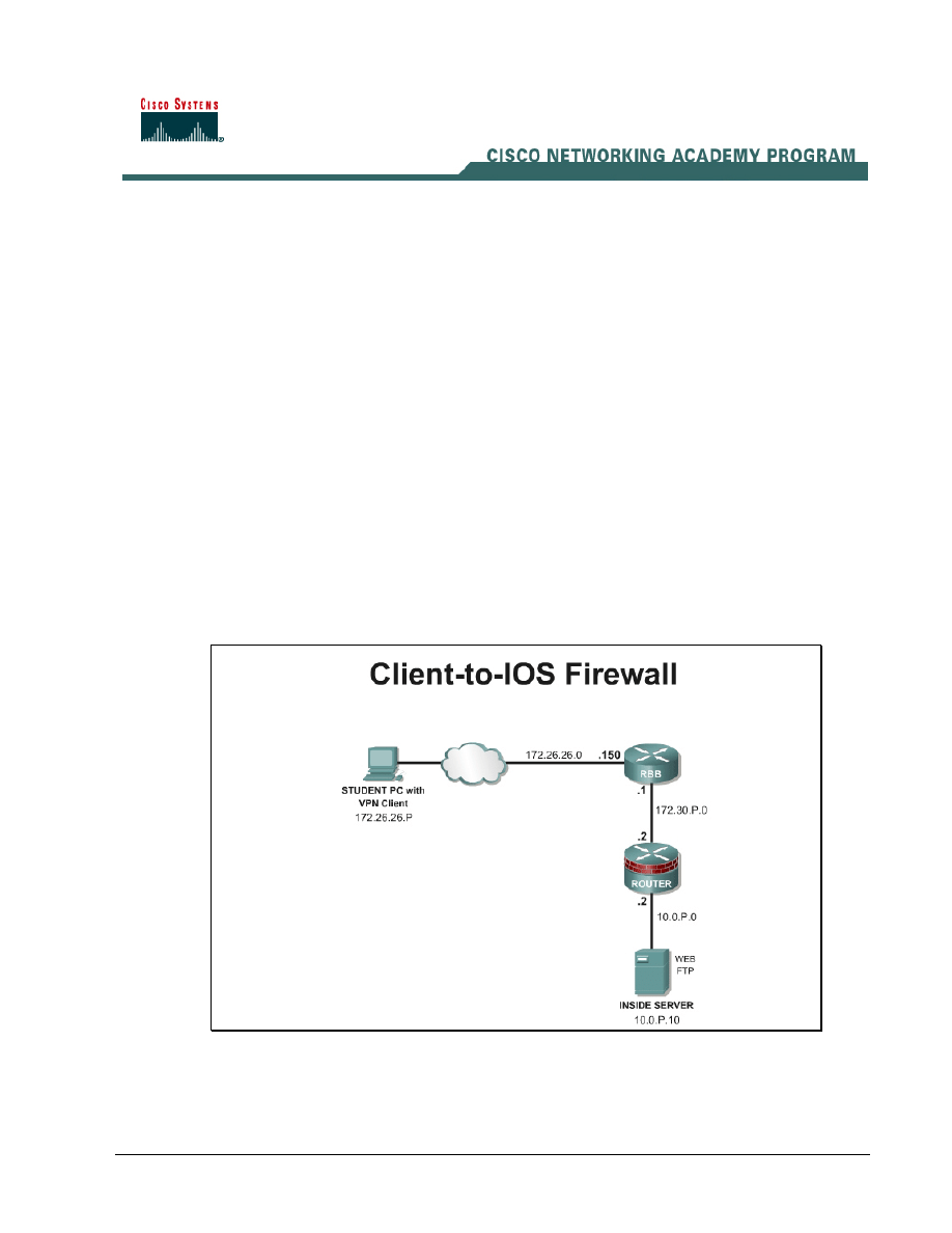
Topology
This figure illustrates the lab network environment.
Preparation
Begin with the topology above and verify the starting configuration on the pod router. Access the
perimeter router console port using the terminal emulator on the Student PC. If desired, save the
1 - 7
Network Security 2 v2.0 – Lab 6.2.12b
Copyright
© 2005, Cisco Systems, Inc.

router configuration to a text file for later analysis. Refer back to the Student Lab Orientation if more
help is needed.
Before beginning this lab exercise, it is imperative to change the static IP address of the student PC
to 172.26.26.P 255.255.255.0 (where P =pod number) with a default gateway of 172.26.26.150 or
obtain an IP address from a DHCP pool configured on RBB. Also, the Student PC must be physically
connected to a switch port on VLAN 1.
Tools and resources
In order to complete the lab, the following is required:
• Standard Client-to-IOS Firewall lab topology
• Console cable
• HyperTerminal
• Cisco VPN Client 4.6 or later
Additional materials
Further information about the objectives covered in this lab can be found at the following websites:
http://www.cisco.com/en/US/products/sw/iosswrel/ps1839/products_feature_guide09186a0080087d1
e.html
Command list
In this lab exercise, the following commands will be used. Refer to this list if assistance or help is
needed during the lab exercise.
Command
Description
access-list
Define an access list permitting those addresses that
are to be translated.
ip nat {inside | outside} |
log {translations syslog}
Mark the interface as connected to the inside or
outside.
ip nat inside source static
local-ip global-ip
Establish static translation between an inside local
address and an inside global address.
Step 1 Verify the Easy VPN Server Configuration
a. Load the starting configuration for the lab. This configuration contains the Easy VPN Server
configuration that was completed in the previous lab.
b. Open the VPN client and click Connect. The User Authentication window opens and several
messages flash by quickly. Complete the following substeps:
i.
When prompted for a username, enter vpnstudent if the username does not already appear
in the text box.
ii. When prompted to enter a password, enter cisco.
iii. Click
OK.
c. The closed lock should now appear in the System tray.
2 - 7
Network Security 2 v2.0 – Lab 6.2.12b
Copyright
© 2005, Cisco Systems, Inc.

d. On the router, the following message should appear.
18:13:54: %CRYPTO-5-SESSION_STATUS: Crypto tunnel is UP . Peer
172.26.26.1:5
00 Id: SALES
e. Disconnect the VPN session. The open lock should appear in the System tray.
f.
On the router, the following message should appear.
18:20:29: %CRYPTO-5-SESSION_STATUS: Crypto tunnel is DOWN. Peer
172.26.26.1:5
00 Id: SALES
Step 2 Configure PAT
a. Define addresses to be translated by creating an extended access list.
RouterP(config)# access-list 150 permit ip 10.0.P.0 0.0.0.255 any
1. What is the purpose of this access list?
__________________________________________________________________________
b. Verify the access list created.
RouterP# show access-list
c. Now connect the access list to a NAT statement.
RouterP(config)#ip nat inside source list 150 interface
fastEthernet0/1 overload
d. Configure the router interface which is connected to the inside network and which interface is
connected to the outside.
RouterP(config)#interface fastEthernet0/0
RouterP(config-if)#ip nat inside
RouterP(config)#interface fastEthernet0/1
RouterP(config-if)#ip nat outside
Step 3 Test the Connectivity
a. From the Student PC on the outside, open a command prompt and ping the inside interface
address on the router at 10.0.P.2
C:\>ping 10.0.P.2
Was it successful?
_____________________________________________________________________________
b. From the Student PC, try to telnet to 10.0.P.2
C:\>telnet 10.0.P.2
Was it successful?
_____________________________________________________________________________
c. From the Student PC, try to make an http connection to 10.0.P.2
http://10.0.P.2
3 - 7
Network Security 2 v2.0 – Lab 6.2.12b
Copyright
© 2005, Cisco Systems, Inc.

Was it successful?
_____________________________________________________________________________
d. Open the VPN client and click Connect. The User Authentication window opens and several
messages flash by quickly. Complete the following substeps:
i.
When prompted for a username, enter vpnstudent if the username does not already appear
in the text box.
ii. When prompted to enter a password, enter cisco.
iii. Click
OK.
e. The closed lock should now appear in the System tray.
f.
From the Student PC on the outside, open a command prompt and ping the inside interface
address on the router at 10.0.P.2
C:\>ping 10.0.P.2
Was it successful?
_____________________________________________________________________________
g. From the Student PC, try to telnet to 10.0.P.2
C:\>telnet 10.0.P.2
Was it successful?
_____________________________________________________________________________
h. From the Student PC, try to connect using SDM to 10.0.P.2
http://10.0.P.2
Was it successful?
_____________________________________________________________________________
i.
Test inside to outside translation. From a workstation or server on the inside network, ping RBB
at 172.26.26.150
C:\>ping 172.26.26.150
Was it successful?
_____________________________________________________________________________
j.
Now verify the routers address translation.
RouterP#show ip nat translations
RouterP#show ip nat translations verbose
RouterP#show ip nat statistics
k. At this point, it should be clear that the PAT is working correctly for traffic originating from the the
inside network, but the remote access connection is not functioning correctly. This is caused by
the return VPN traffic being translated. The translation invalidated the return VPN packet. In the
next step, this problem is easily fixed.
Step 4 Modify the PAT ACL
a. Define the inside addresses to be translated while excluding the VPN traffic from translation.
First, clear the access list.
RouterP(config)# no access-list 150
RouterP(config)# access-list 150 deny ip 10.0.P.0 0.0.0.255 11.0.P.0
0.0.0.255 log
4 - 7
Network Security 2 v2.0 – Lab 6.2.12b
Copyright
© 2005, Cisco Systems, Inc.

Note
Notice that the local 10.0.P.0 network is define as the source and the 11.0.P.0 remote address pool is
the destination.
RouterP(config)# access-list 150 permit ip 10.0.P.0 0.0.0.255 any
b. Right click on the closed lock icon in the system try and select Disconnect from the menu.
c. Reopen the VPN client and click Connect. The User Authentication window opens and several
messages flash by quickly. Complete the following substeps:
i.
When prompted for a username, enter vpnstudent if the username does not already appear
in the text box.
ii. When prompted to enter a password, enter cisco.
iii. Click
OK.
d. The closed lock should now appear in the System tray.
e. From the Student PC on the outside, open a command prompt and ping the inside interface
address on the router at 10.0.P.2
C:\>ping 10.0.P.2
Was it successful?
_____________________________________________________________________________
f.
From the Student PC, try to telnet to 10.0.P.2. Log into the router using sdm/sdm
C:\>telnet 10.0.P.2
Was it successful?
_____________________________________________________________________________
g. From the Student PC, try to connect using SDM to 10.0.P.2. Log into the router using sdm/sdm
http://10.0.P.2
Was it successful?
_____________________________________________________________________________
Step 5 Modify the PAT ACL using SDM
In this step, define the inside addresses to be translated while excluding the VPN traffic from
translation
a. Remove the NAT configuration or load the startup configuration.
b. From the Student PC on the outside, connect to the router using SDM.
http://10.0.P.2
Note
When the SDM session is initiated at the inside interface of the router, the session is protected by the
VPN tunnel.
c. Click on the Configure button at the top of the SDM interface.
d. Click
the
NAT button in the Tasks panel.
e. Click on the Designate NAT Interfaces button.
f.
Verify that the appropriate inside and outside interfaces are checked and click OK.
g. Click on the Add button in the Network Address Translation Rule area.
h. The
Add Address Translation Rule window appears. Choose the Dynamic radio button.
5 - 7
Network Security 2 v2.0 – Lab 6.2.12b
Copyright
© 2005, Cisco Systems, Inc.
i.
Define an ACL rule using the … button. Click on Create a new rule (ACL) and select option.
j.
Name the extended ACL as NAT_ACL with a description of ACL for NAT
k. Click on the Add button to define the first ACL statement which will deny traffic from the remote
VPN network, 11.0.P.0/24, to the local LAN network, 10.0.P.0/24. Log this traffic.
l.
Add a second ACL to translate all inside 10.0.P.0 traffic.
m. Click the OK button to complete the Rule and return to the Add Address Translation Rule
window.
n. Choose the outside interface to translate to.
a. Type:
Interface
b. Interface:
Fa0/1
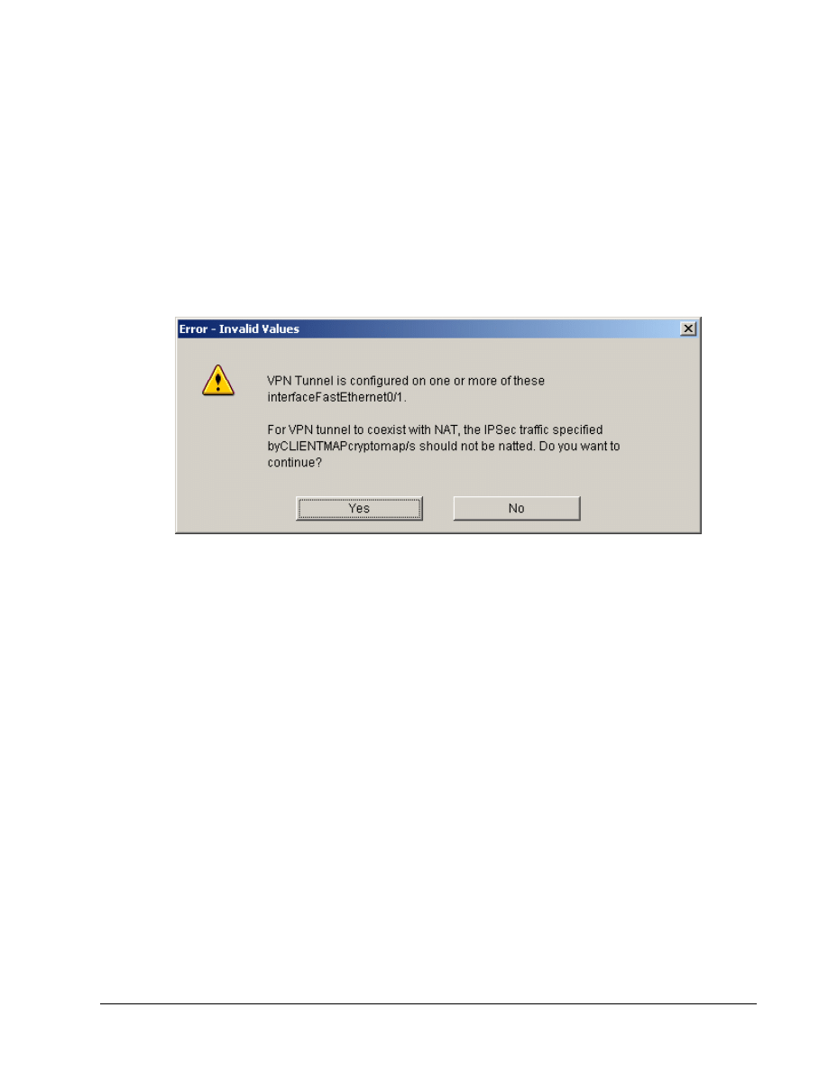
o. Click
OK. An Error-Invalid Values window will appear.
p. Click
the
Yes button.
q. Click on the Deliver button.
r. The Command Delivery Status window will appear, click the OK button to continue. The
configuration from Router1 is shown below.
ip access-list extended NAT_ACL
remark ACL for NAT
remark SDM_ACL Category=2
remark Except remote access VPN traffic from translation
deny ip 10.0.1.0 0.0.0.255 11.0.1.0 0.0.0.255 log
remark Translate all Inside traffic
permit ip 10.0.1.0 0.0.0.255 any
exit
interface FastEthernet0/1
ip nat outside
exit
interface FastEthernet0/0
ip nat inside
exit
route-map SDM_RMAP_1 permit 1
match ip address NAT_ACL
exit
6 - 7
Network Security 2 v2.0 – Lab 6.2.12b
Copyright
© 2005, Cisco Systems, Inc.

ip nat inside source route-map SDM_RMAP_1 interface FastEthernet0/1
overload
s. Notice that SDM uses a route map in the NAT configuration. This accomplished the same
translation process as configured in previous steps.
t. Exit
SDM.
Step 6 Test the SDM Configuration
a. Right click on the closed lock icon in the system try and select Disconnect from the menu.
b. Reopen the VPN client and click Connect. The User Authentication window opens and several
messages flash by quickly. Complete the following substeps:
i.
When prompted for a username, enter vpnstudent if the username does not already appear
in the text box.
ii. When prompted to enter a password, enter cisco.
iii. Click
OK.
c. The closed lock should now appear in the System tray.
d. On the router, the following message should appear.
18:13:54: %CRYPTO-5-SESSION_STATUS: Crypto tunnel is UP . Peer
172.26.26.1:5
00 Id: SALES
e. From the Student PC on the outside, open a command prompt and ping the inside interface
address on the router at 10.0.P.2
C:\>ping 10.0.P.2
Was it successful?
_____________________________________________________________________________
f.
From the Student PC, try to telnet to 10.0.P.2. Log into the router using sdm/sdm
C:\>telnet 10.0.P.2
Was it successful?
_____________________________________________________________________________
g. From the Student PC, try to connect to the pod router web inside interface located at 10.0.P.2.
Log into the router using sdm/sdm
http://10.0.P.2
Was it successful?
_____________________________________________________________________________
h. Now verify the address translation. If traffic has not originated from the LAN, then no
translations should appear.
RouterP#show ip nat translations
RouterP#show ip nat translations verbose
RouterP#show ip nat statistics
7 - 7
Network Security 2 v2.0 – Lab 6.2.12b
Copyright
© 2005, Cisco Systems, Inc.
Wyszukiwarka
Podobne podstrony:
więcej podobnych podstron