STEERING SYSTEM
A1.00-1.50XL (A20-30XL) [C203]
PART NO. 1482620
1600 SRM 796

SAFETY PRECAUTIONS
MAINTENANCE AND REPAIR
• When lifting parts or assemblies, make sure all slings, chains, or cables are correctly
fastened, and that the load being lifted is balanced. Make sure the crane, cables, and
chains have the capacity to support the weight of the load.
• Do not lift heavy parts by hand, use a lifting mechanism.
• Wear safety glasses.
• DISCONNECT THE BATTERY CONNECTOR before doing any maintenance or repair
on electric lift trucks.
• Disconnect the battery ground cable on internal combustion lift trucks.
• Always use correct blocks to prevent the unit from rolling or falling. See HOW TO PUT
THE LIFT TRUCK ON BLOCKS in the Operating Manual or the Periodic Mainte-
nance section.
• Keep the unit clean and the working area clean and orderly.
• Use the correct tools for the job.
• Keep the tools clean and in good condition.
• Always use HYSTER APPROVED parts when making repairs. Replacement parts
must meet or exceed the specifications of the original equipment manufacturer.
• Make sure all nuts, bolts, snap rings, and other fastening devices are removed before
using force to remove parts.
• Always fasten a DO NOT OPERATE tag to the controls of the unit when making repairs,
or if the unit needs repairs.
• Be sure to follow the WARNING and CAUTION notes in the instructions.
• Gasoline, Liquid Petroleum Gas (LPG), Compressed Natural Gas (CNG), and Diesel fuel
are flammable. Be sure to follow the necessary safety precautions when handling these
fuels and when working on these fuel systems.
• Batteries generate flammable gas when they are being charged. Keep fire and sparks
away from the area. Make sure the area is well ventilated.
NOTE:
The following symbols and words indicate safety information in this
manual:
WARNING
Indicates a condition that can cause immediate death or injury!
CAUTION
Indicates a condition that can cause property damage!

Steering System
Table of Contents
TABLE OF CONTENTS
General ...............................................................................................................................................................
Description .........................................................................................................................................................
Steering Wheel and Column Assembly ........................................................................................................
Steering Control Unit Repair ............................................................................................................................
Remove ...........................................................................................................................................................
Install .............................................................................................................................................................
Hydraulic Steering Motor Repair......................................................................................................................
Description .....................................................................................................................................................
Remove ...........................................................................................................................................................
Disassemble ...................................................................................................................................................
Clean and Inspect ..........................................................................................................................................
Assemble ........................................................................................................................................................
Install .............................................................................................................................................................
Direction Control Lever Repair .........................................................................................................................
Remove ...........................................................................................................................................................
Assemble ........................................................................................................................................................
Install .............................................................................................................................................................
Power Steering Adjustments.............................................................................................................................
Air in Steering System ..................................................................................................................................
Steering Pressure ..........................................................................................................................................
Steering Chain, Adjust ..................................................................................................................................
Troubleshooting..................................................................................................................................................
This section is for the following models:
A1.00-1.50XL (A20-30XL) [C203]
©2002 HYSTER COMPANY
i

"THE
QUALITY
KEEPERS"
HYSTER
APPROVED
PARTS
1600 SRM 796
Description
General
The A1.00-1.50XL (A20-30XL) series of lift trucks
have a power steering system.
This manual de-
scribes the disassembly and assembly of the power
steering system for repairs. There is a description
for each part of the steering system at the beginning
of each repair section. The steering system rotates
the master drive unit (MDU) to steer the lift truck.
Additional information for the components of the
steering system is found in the following manuals.
Master Drive Unit (ZF) 630 SRM 794
Master Drive Unit (Kordel) 630 SRM 795
Steering Control Unit 1600 SRM 797
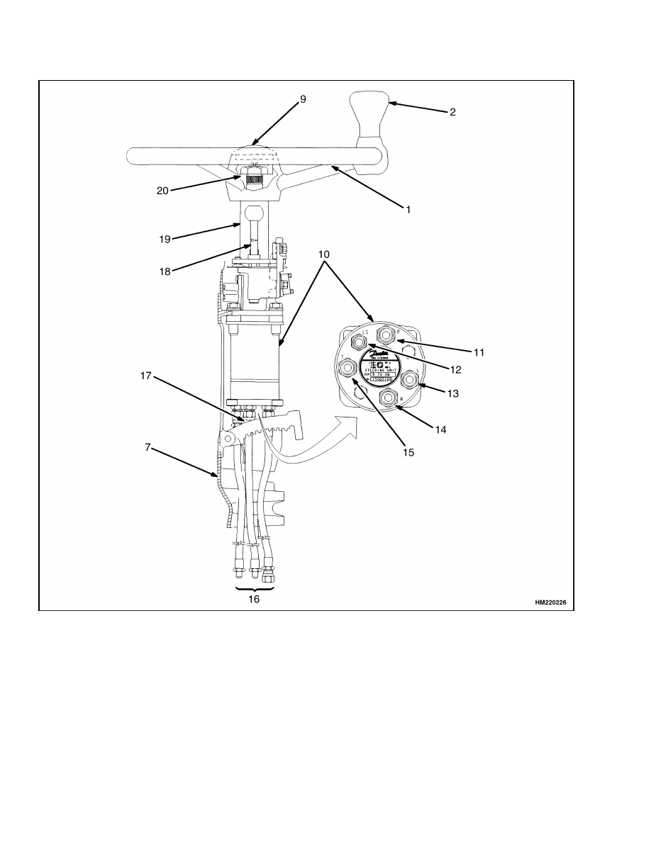
Description
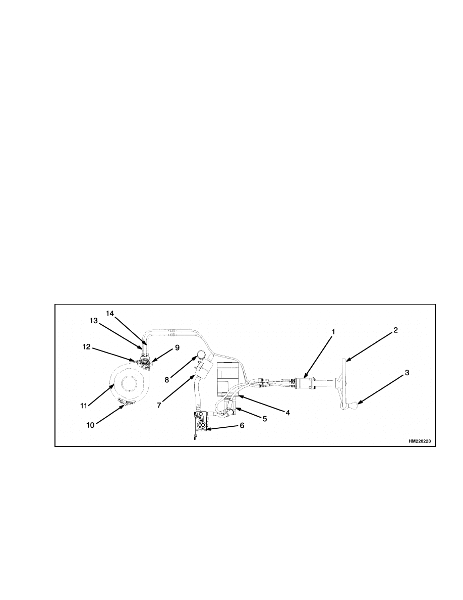
The power steering system is a hydraulic system that
does not have a mechanical link between the steer-
ing wheel and the hydraulic motor. See Figure 1.
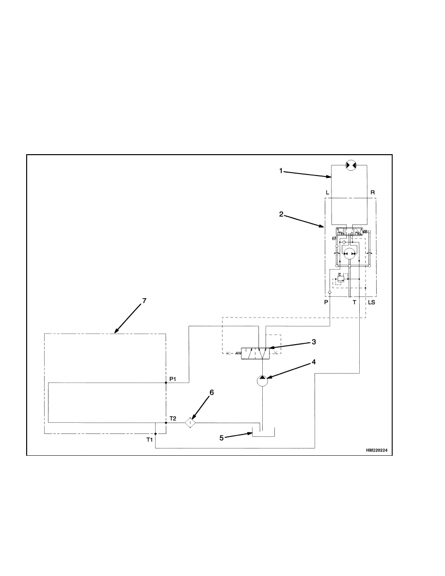
The control of the steering is through a hydraulic
circuit. An electric motor for the steering pump is
energized when the key switch is in the ON posi-
tion and the seat switch is closed. When the elec-
tric motor operates the steering pump, hydraulic oil
flows through the power steering system. See Fig-
ure 2. The hydraulic oil flows from the main hy-
draulic pump through the flow divider to the steering
control unit and returns to the hydraulic tank via the
control valve when the steering wheel is not being ro-
tated.
The steering control unit is an open-center rotary
pump operated by the steering wheel.
With the
key switch ON and the seat switch open, the main
hydraulic motor runs at low speed.
Any flow of
hydraulic oil unused by the steering system is di-
verted through a priority flow divider to the truck
hydraulics and back to the hydraulic tank. When
the steering wheel is rotated, the steering control
unit senses a demand and more oil is diverted to the
steering via the load-sensing feedback line to the
flow divider, which then loads the hydraulic motor.
The hydraulic motor slowly rotates the complete
master drive unit and steer wheel using a chain
drive connection.
1.
STEERING CONTROL UNIT
2.
STEERING WHEEL
3.
SPINNER KNOB
4.
HYDRAULIC PUMP AND MOTOR ASSEMBLY
5.
FLOW DIVIDER
6.
HYDRAULIC CONTROL VALVE
7.
HYDRAULIC FILTER
8.
HYDRAULIC DIPSTICK
9.
STEERING MOTOR
10. STEERING CHAIN ADJUSTMENT
11. MASTER DRIVE UNIT
12. STEERING CHAIN
13. STEERING HOSE - RIGHT
14. STEERING HOSE - LEFT
Figure 1. Power Steering Components
1
Description
1600 SRM 796
If the steering pump does not operate, a check valve
closes and permits the steering control unit to con-
tinue control of the steering system. The lift truck is
difficult to steer when the steering pump is not op-
erating, but the steering control unit can operate the
hydraulic motor and make steering possible.
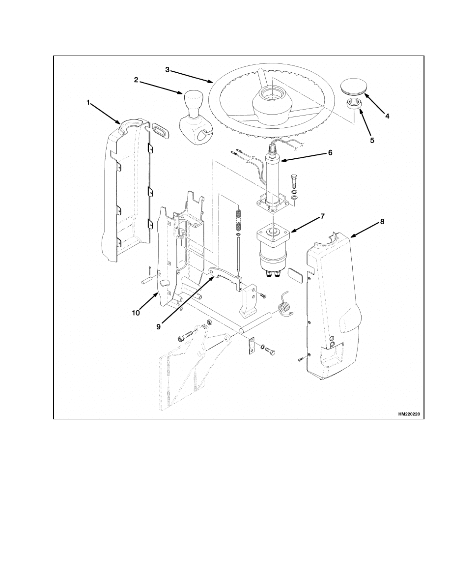
STEERING WHEEL AND COLUMN
ASSEMBLY
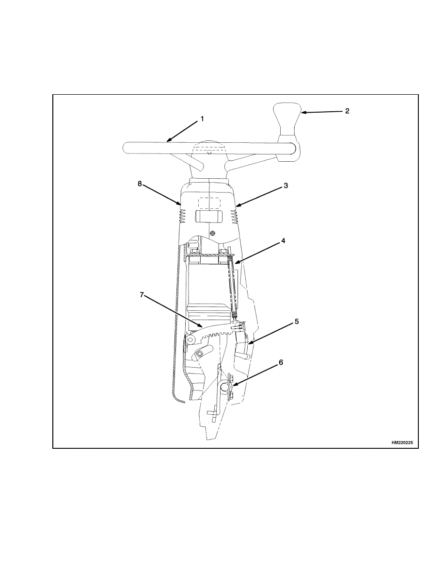
The steering wheel attaches to the steering shaft
with splines. See Figure 3 and Figure 4. A large
nut holds the steering wheel onto the steering shaft.
The electrical horn button is the cover for the center
of the steering wheel. The lower end of the steering
shaft has splines that engage the steering control
unit. The horn functions by using brushes and slip
rings on the steering shaft.
1.
HYDRAULIC STEERING MOTOR
2.
STEERING CONTROL UNIT
3.
FLOW DIVIDER
4.
HYDRAULIC PUMP AND MOTOR ASSEMBLY
5.
HYDRAULIC TANK
6.
HYDRAULIC FILTER
7.
HYDRAULIC CONTROL VALVE
Figure 2. Steering System Hydraulic Schematic
2
1600 SRM 796
Description
The steering column is adjustable with five tilt posi-
tions for operator comfort. It also provides additional
clearance for removing the battery. A latch holds the
steering column in position.
A cover on the steering column gives access to the
steering control unit, the key switch, and the direc-
tion switches.
Figure 3. Steering Wheel and Steering Column Assembly (Sheet 1 of 2)
3
Description
1600 SRM 796
1.
STEERING WHEEL
2.
KNOB SPINNER
3.
LOWER STEERPOD COVER
4.
TILT ROD AND SPRINGS
5.
LATCH KNOB
6.
TILT SPRING
7.
TILT LATCH
8.
UPPER STEERPOD COVER
9.
HORN BUTTON
10. STEERING CONTROL UNIT
11. INPUT
12. LOAD SENSING
13. LEFT TURN
14. RIGHT TURN
15. OUTPUT
16. HYDRAULIC HOSES
17. STEERING COLUMN BRACKET
18. SHIFT LEVER ASSEMBLY (WITHOUT
MONOTROL)
19. STEERING COLUMN
20. STEERING COLUMN NUT
Figure 3. Steering Wheel and Steering Column Assembly (Sheet 2 of 2)
4
1600 SRM 796
Description
1.
UPPER STEERING COLUMN COVER
2.
KNOB SPINNER
3.
STEERING WHEEL
4.
HORN BUTTON
5.
STEERING COLUMN NUT
6.
STEERING COLUMN
7.
STEERING CONTROL UNIT
8.
LOWER STEERING COLUMN COVER
9.
TILT LATCH
10. STEERING COLUMN BRACKET
Figure 4. Disassembled Steering Wheel and Steering Column Assembly
5

Steering Control Unit Repair
1600 SRM 796
Steering Control Unit Repair
REMOVE
1.
Disconnect the battery. Raise the steering col-
umn to the UP position. Remove the front and
rear access covers from the steering column. See
Figure 3.
2.
Remove the key switch from the housing of the
steering column. Make an identification of the
electrical wires and disconnect them from the key
switch. Prevent damage to the wire harness.
3.
Remove the horn button and disconnect the horn
connections at both ends. The horn button, steer-
ing wheel, direction switches, and steering shaft
can be removed as an assembly. It is not easy to
get the wheel off the shaft.
4.
Remove the large hex nut, and pull the steering
wheel from the shaft.
5.
If the truck is equipped with a direction control
lever, disconnect the wiring harness to the direc-
tion control lever assembly and remove the direc-
tion control lever. See the section Direction Con-
trol Lever Repair, Remove.
6.
Make an identification of the hydraulic hoses at
the steering control unit so that the hydraulic
hoses can be correctly connected during assem-
bly. The hydraulic hoses have swivel ends and
can be disconnected at the hand pump end with
no need to disconnect the other end.
7.
To remove the steering shaft from the steering
column, remove the four capscrews which hold
the hand pump to the column bracket.
INSTALL
1.
Place both the steering control unit and the
steering column on the underside of the flange
in the steering column bracket. Make sure that
the shaft of the steering column mates with the
spline of the steering control unit. See Figure 3.
2.
Fasten the steering column to the steering
control unit with four capscrews and washers.
Tighten to 19 N•m (168 lbf in).
3.
Fasten the steering column and the steering con-
trol unit to the steering column bracket. Next,
install the steering column bracket to the frame
swivel using the hardware taken off during the
removal procedure.
4.
Install the steering wheel with one spoke toward
the mast. Install the large hex nut onto the steer-
ing shaft.
5.
Install the key switch and connect the electrical
wires.
WARNING
Connection of the hydraulic hoses to the hand
pump requires minimal torque.
Torque the
four 11/16-inch fittings to 30 N•m (22 lbf ft) and
the 9/16-inch fitting to 25 N•m (18 lbf ft). Fail-
ure to follow these torque recommendations
can snap the fittings and cause injury.
6.
Connect the hydraulic hoses to the steering con-
trol unit. Make sure each hydraulic hose is con-
nected to the correct port on the steering control
unit.
7.
Install the hydraulic hoses through the frame
and connect them to the correct connections on
the hydraulic steering motor, the steering pump,
and the main control valve.
8.
Connect the wires at the bottom of the steering
column. Install the front and rear access covers
onto the steering column.
6
1600 SRM 796
Hydraulic Steering Motor Repair
Hydraulic Steering Motor Repair
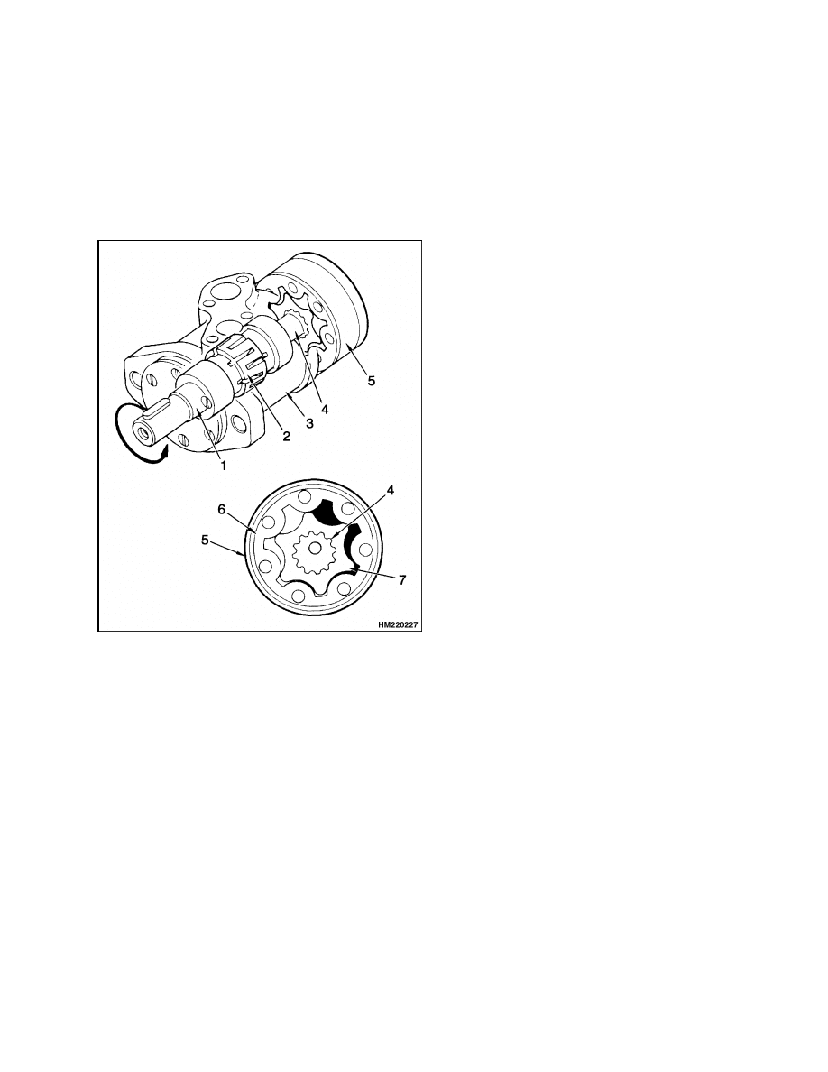
DESCRIPTION
The hydraulic steering motor controls the steering
function of the master drive unit (MDU) using a
steering chain. See Figure 5. The hydraulic motor
rotates the MDU for steering the lift truck.
1.
OUTPUT SHAFT
2.
DISTRIBUTOR VALVE (PART OF OUTPUT
SHAFT)
3.
MOTOR HOUSING
4.
CENTER SHAFT
5.
GEAR WHEEL SET
6.
FIXED GEAR RIM
7.
GEAR WHEEL
Figure 5. Hydraulic Steering Motor Operation
The hydraulic steering motor uses a gear wheel set
inside of the motor to change hydraulic energy into
mechanical energy. The gear wheel set has a fixed
gear rim and a gear wheel. The center of the gear
wheel moves around the center of the gear rim at the
same time the gear wheel rotates. The directions of
these two motions are opposite. See Figure 5. The
center of the gear wheel moves around the center
of the gear rim six times per revolution of the gear
wheel.
The part of the output shaft which is in the motor
housing has two purposes: an output shaft and a dis-
tributor valve. The distributor valve rotates with the
gear wheel. This distributor valve sends oil to the
pressure chambers of the gear wheel set and away
from the return chambers.
REMOVE
NOTE:
Most service personnel remove the counter-
weight from the lift truck for this procedure. The
hydraulic steering motor can be removed without re-
moving the counterweight. Removing the counter-
weight provides better access to the hydraulic steer-
ing motor, steering chain, and the MDU. See the sec-
tion Frame 100 SRM 793 for the procedure to re-
move the counterweight.
1.
Loosen the locking nut and the adjustment screw
on the steering chain and remove the steering
chain.
2.
Identify the two hydraulic hoses to the hydraulic
motor and disconnect them. Put caps over the
ends of the hydraulic hose connectors.
3.
Remove the two capscrews that fasten the hy-
draulic motor to the lift truck frame and remove
the motor.
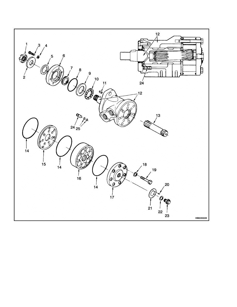
DISASSEMBLE
1.
Put the motor in a vise or other holding tool. See
Figure 6. If a vise is used, do not cause distortion
of the motor housing. Use a vise with soft jaws.
2.
Place a matchmark on all sections of the steering
motor to ensure correct assembly of the steering
motor.
3.
Remove the capscrews from the end cover. Slide
the end cover from the motor.
4.
Lift the gear set and remove the O-rings. Remove
the distributor plate.
5.
Remove the center shaft.
Remove the output
shaft from the housing.
6.
From the other end of the housing, remove the
screws from the flange cover. Remove the flange
cover. Remove the O-ring and bearing race from
the flange cover.
7
Hydraulic Steering Motor Repair
1600 SRM 796
1.
CASTLE NUT
2.
WASHER
3.
CAPSCREW
4.
SPRING WASHER
5.
DUST SEAL RING
6.
FLANGE COVER
7.
SHAFT SEAL
8.
O-RING
9.
BEARING RACE
10. NEEDLE BEARING
11. WOODRUFF KEY
12. OUTPUT SHAFT AND MOTOR
HOUSING (MATCHED SET)
13. CENTER SHAFT
14. O-RING
15. DISTRIBUTOR PLATE
16. GEAR WHEEL SET
17. END COVER
18. WASHER
19. CAPSCREW
20. SCREW
21. NAMEPLATE
22. WASHER
23. DRAIN PLUG
24. CHECK VALVE
25. O-RING
Figure 6. Hydraulic Steering Motor
8
1600 SRM 796
Hydraulic Steering Motor Repair
7.
Use a screwdriver to loosen and remove the shaft
seal from the flange cover. Remove the dust seal
from the flange cover.
8.
Remove the needle bearings.
CLEAN AND INSPECT
1.
Clean all parts with a mineral oil cleaning sol-
vent.
2.
Check all parts and replace the parts that are
worn or damaged.
3.
Lubricate all parts with hydraulic oil during as-
sembly.
ASSEMBLE
1.
Put the shaft seal in the flange cover. See Fig-
ure 6. Use a plastic hammer and carefully install
the shaft seal.
2.
Put the dust seal ring in the outer face of the
flange cover. Put a steel block over the dust seal
ring to help installation. Use a hammer against
the steel block.
3.
Put the shaft seal, O-ring, bearing race, and nee-
dle bearing into the opposite side of the flange
cover. Use a thin coat of grease on the O-ring to
hold it in position.
4.
Install the flange cover on the motor housing.
Put the spring washers onto the six screws and
fasten the flange cover onto the motor housing.
Tighten the screws to 5 to 8 N•m (45 to 70 lbf in).
5.
Turn the motor over and install the output shaft
into the motor housing.
6.
Put the motor in a horizontal position and install
the Woodruff key into the end of the output shaft.
Put tape over the Woodruff key and shaft to hold
the Woodruff key in position until installation.
7.
Install the thrust bearing in the motor housing.
Install the O-ring and distributor plate so that
the screw holes align with the holes in the motor
housing. Use a thin layer of grease on the O-ring.
8.
Slide the center shaft into the motor housing and
hold the end of the shaft. Make a tool of thin
metal to fit under the splines of the center shaft
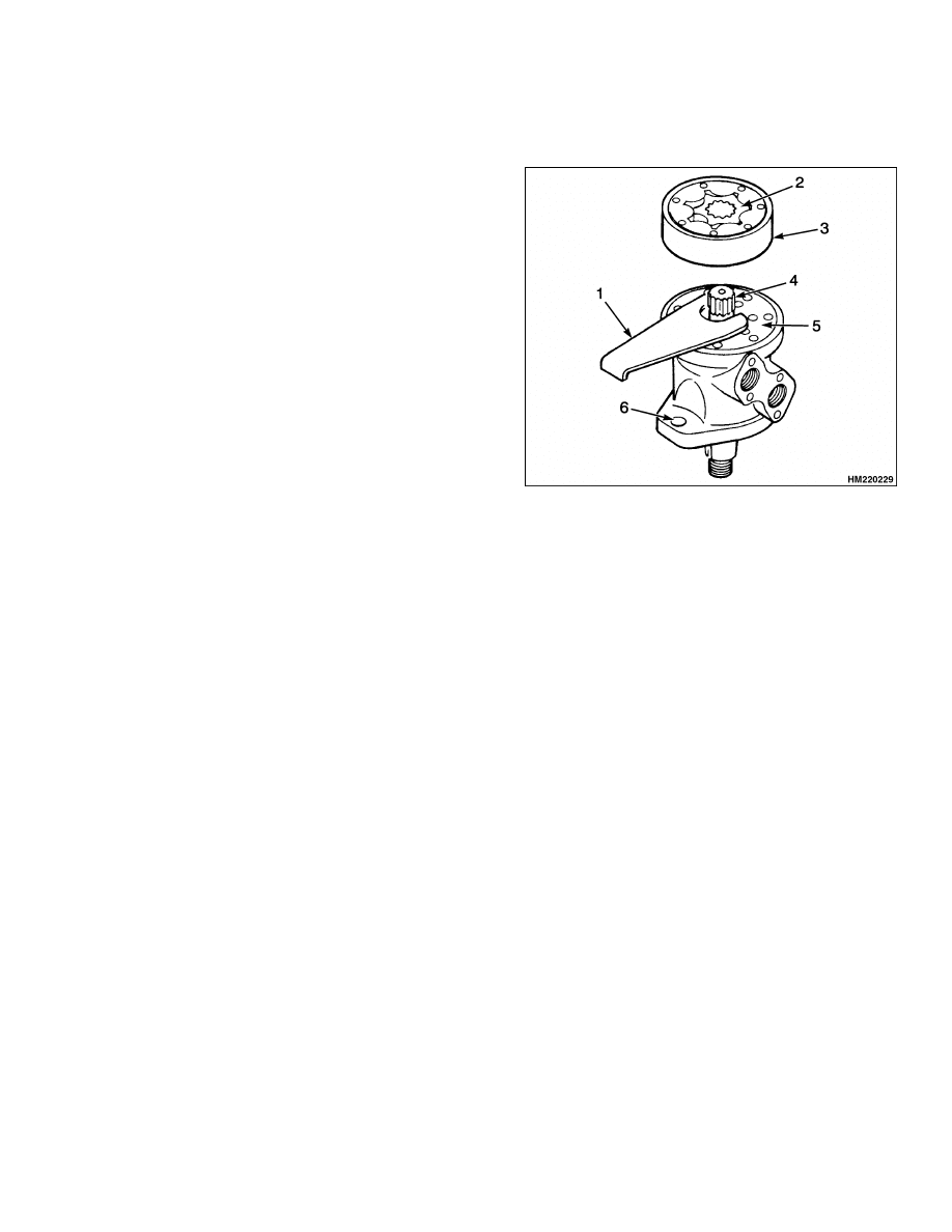
and hold the shaft in position. See Figure 7.
1.
HOLDING TOOL
2.
ROTOR
3.
GEAR WHEEL SET
4.
CENTER SHAFT
5.
DISTRIBUTOR
PLATE
6.
HOLE IN
MOUNTING
FLANGE OF
MOTOR
Figure 7. Assembly of Gear Wheel Set
9.
Install the distributor plate, gear wheel set, and
O-rings over the end of the center shaft. Use a
thin coat of grease to hold the O-rings in posi-
tion. Align the screw holes with the holes in the
housing and distributor plate. Adjust the gear
wheel (rotor) so that a line between the tops of
two opposite teeth is parallel with the holes in
the mounting flange of the motor (correct direc-
tion of rotation). See Figure 7.
10. Install the end cover and O-ring over the gear
wheel set and install the six capscrews with new
washers. Remove the holding tool from the cen-
ter shaft. Tighten the capscrews in the end cover
to 30 to 36 N•m (22 to 25 lbf ft).
11. Insert plastic plugs into the inlet and outlet ports
or cover them with tape to prevent dirt from en-
tering the motor before installation.
9
Direction Control Lever Repair
1600 SRM 796
INSTALL
1.
Put the hydraulic motor into position in the lift
truck frame and install the two capscrews.
2.
Connect the two hydraulic hoses to their correct
ports on the hydraulic motor.
3.
Install the steering chain. See Steering Chain,
Adjust for making adjustments to the steering
chain.
4.
Install the counterweight.
Direction Control Lever Repair
REMOVE
1.
Disconnect the battery. Raise the steering col-
umn to the UP position. Remove the front and
rear access covers from the steering column.
2.
Remove the key switch from the housing of the
steering column. Make an identification of the
electrical wires and disconnect them from the key
switch. Prevent damage to the wire harness.
3.
Remove the horn button and disconnect the horn
connections at both ends.
4.
Remove the large hex nut and pull the steering
wheel from the shaft.
5.
Disconnect the wiring harness to the direction
control lever assembly and remove the direction
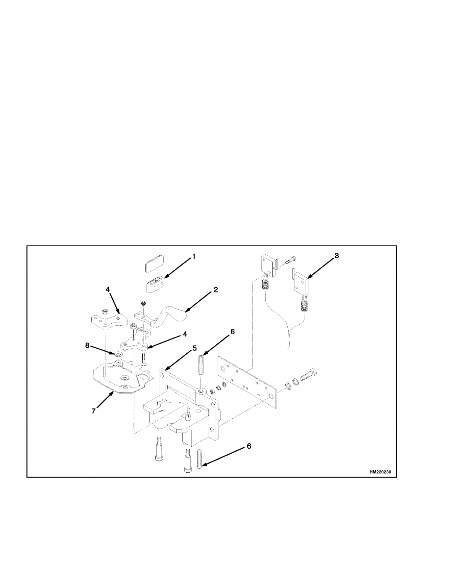
control lever from the steering column. The di-
rection control lever is shown disassembled in
Figure 8.
1.
DIRECTION INDICATOR
2.
SHIFT LEVER
3.
FORWARD/REVERSE MICROSWITCHES
4.
SWITCH CRANKS
5.
SHIFT LEVER BASE
6.
SPRING PLUNGER
7.
SHIFT LEVER LINK
8.
SPRING WASHER
Figure 8. Direction Shift Lever (Without MONOTROL)
10
1600 SRM 796
Power Steering Adjustments
ASSEMBLE
1.
To assemble the direction control lever, install
the link plate and the cranks. Place the spring
washers on the pins between the link plate and
the cranks. See Figure 8.
2.
Lubricate the pins on both sides of the cranks
and fill the detents on the crank assembly with
HCE-38 grease. Tighten the nut to 10.8 N•m
(95.6 lbf in).
3.
Install the shift lever handle and tighten both the
nut and the capscrew to 6.33 N•m (56 lbf in).
4.
Install the spring plunger in both the top and bot-
tom of the shift lever base. Screw the plunger in
until it touches the crank and back off one turn.
INSTALL
1.
Install the shift lever onto the steering column.
2.
Connect the wiring harness to the direction con-
trol lever assembly.
3.
Install the steering wheel on the steering col-
umn and install the large hex nut on the shaft.
Tighten the nut to 40 to 54 N•m (30 to 40 lbf ft).
4.
Connect the horn connections at both ends and
install the horn button.
5.
Install the key switch in the steering column
housing and connect the key switch wiring.
6.
Install the front and rear access covers to the
steering column.
Power Steering Adjustments
AIR IN STEERING SYSTEM
If there is air in the hydraulic lines of the steering
system, the operation will not be constant. Rotate
the steering wheel from stop to stop several times to
remove the air from the steering system. If the air
cannot be removed from the steering system, check
for leaks at the power steering pump. If the O-ring
or the oil seal between the power steering motor and
pump has a defect, air will enter the hydraulic sys-
tem.
STEERING PRESSURE
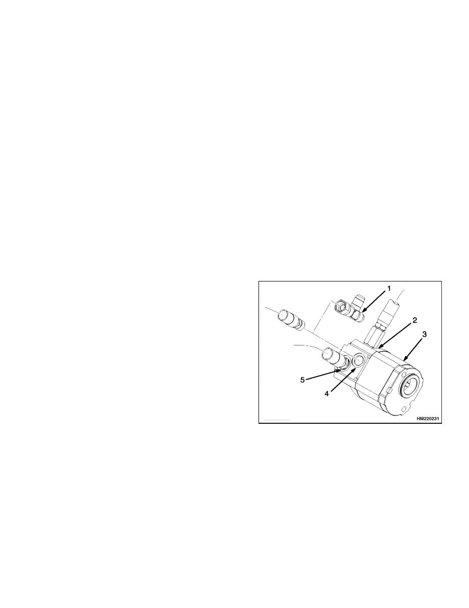
1.
Temporarily install a tee fitting in the priority
port of the flow divider. See Figure 9. Connect
a 20 MPa (3000 psi) gauge onto the tee fitting.
2.
Operate the power steering pump and steering
for a complete turn. Check that the maximum
pressure is 11.17 to 11.67 MPa (1620 to 1690 psi).
3.
If the pressure is greater than 11.67 MPa
(1690 psi), replace the relief valve. If the pres-
sure is less than 11.17 MPa (1620 psi), check
that the flow divider is not worn or damaged.
4.
When the pressure checks are complete, return
the steering system to normal operation.
1.
PRESSURE TEST
TEE
2.
LOAD SENSING
PORT
3.
FLOW DIVIDER
4.
PRESSURE PORT
(PRIORITY)
5.
EXCESS FLOW
PORT
Figure 9. Pressure Check
11
Troubleshooting
1600 SRM 796
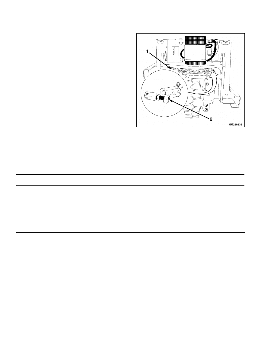
STEERING CHAIN, ADJUST
To remove slack or to tighten the steering chain, do
the following. See Figure 10.
1.
Raise the lift truck to remove the weight of the
lift truck from the MDU.
2.
Loosen the locking nut on the adjustment assem-
bly.
3.
Press the chain at the mid-point of the longest
run. Adjust the adjustment screw until there is
movement of the chain of 7 to 11 mm (0.27 to
0.43 in.).
4.
Tighten the lock nut and recheck the chain move-
ment.
5.
Rotate the MDU through the full range of travel
to ensure that there is no binding or loosening of
the steering chain.
1.
CHECK CHAIN ADJUSTMENT HERE
2.
MAKE ADJUSTMENT HERE
Figure 10. Steering Chain Adjustment
Troubleshooting
PROBLEM
POSSIBLE CAUSE
PROCEDURE OR ACTION
Steering is slow or more dif-
ficult than normal.
The steer pump is worn. Check the
hydraulic pressure.
Replace the steering pump.
The spring for the relief valve is
weak or damaged.
Replace the spring.
The steering control unit has a de-
fect.
See the section the Steering Con-
trol Unit 1600 SRM 797.
The MDU does not turn
when the steering wheel is
turned.
Air in the steering hydraulic system.
Bleed the air from the steering sys-
tem.
Steering pump does not send oil to
the steering system.
Replace the steering pump.
The relief valve for the steering sys-
tem is open (damaged).
Replace the relief valve.
The steering control unit has a de-
fect.
See the section Steering Control
Unit 1600 SRM 797.
12

1600 SRM 796
Troubleshooting
PROBLEM
POSSIBLE CAUSE
PROCEDURE OR ACTION
The master drive unit ro-
tates in the wrong direc-
tion from the direction of
the steering wheel.
The hydraulic lines are wrong at the
hydraulic steering motor.
Connect the hydraulic hoses to the
correct port.
The hydraulic lines are wrong at the
steering control unit.
Connect the hydraulic hoses to the
correct port.
The steering control unit was assem-
bled incorrectly after disassembly.
Check the rotor for correct align-
ment.
The master drive unit con-
tinues to turn after the steer-
ing wheel has stopped turn-
ing.
A centering spring is broken in the
steering control unit.
Replace the centering pin in the
steering control unit.
There is damage to the sleeve or the
spool of the steering control unit.
Replace the damaged part.
Check for dirt in the hydraulic sys-
tem and the steering control unit.
Replace the hydraulic fluid and clean
the steering control unit.
The power steering motor
makes noise that is not nor-
mal.
There is air entering the power steer-
ing pump.
Check for air entering the pump
through the inlet port or the seals
between the pump and the motor.
13

NOTES
____________________________________________________________
____________________________________________________________
____________________________________________________________
____________________________________________________________
____________________________________________________________
____________________________________________________________
____________________________________________________________
____________________________________________________________
____________________________________________________________
____________________________________________________________
____________________________________________________________
____________________________________________________________
____________________________________________________________
____________________________________________________________
____________________________________________________________
____________________________________________________________
____________________________________________________________
____________________________________________________________
____________________________________________________________
____________________________________________________________
14

TECHNICAL PUBLICATIONS
1600 SRM 796
3/00 Printed in United Kingdom
Document Outline
- toc
Wyszukiwarka
Podobne podstrony:
1482623 1800SRM0803 (03 2000) UK EN
1482617 1600SRM0797 (03 2000) UK EN
897953 1600SRM0639 (03 2005) UK EN
897986 1600SRM0658 (03 1997) UK EN
1482603 0100SRM0793 (03 2000) UK EN
1453608 1600SRM0687 (03 2002) UK EN
897983 1600SRM0655 (03 2002) UK EN
1554628 1600SRM1075 (03 2004) UK EN
1482632 8000SRM0798 (03 2000) UK EN
1482626 1900SRM0802 (04 2000) UK EN
897953 1600SRM0639 (03 2005) UK EN
więcej podobnych podstron