
BRITISH STANDARD
DD ENV
1992-1-1:1992
Eurocode 2: Design of
concrete structures —
Part 1: General rules and rules for
buildings —
(together with United Kingdom
National Application Document)
Licensed copy:Heriot Watt University, 20/04/2004, Uncontrolled Copy, © BSI

DD ENV 1992-1-1:1992
This Draft for Development,
having been prepared under
the direction of the Technical
Sector Board for Building and
Civil Engineering (B/-), was
published under the authority
of the Standards Board and
comes into effect on
15 May 1992
© BSI 11-1999
The following BSI reference
relates to the work on this Draft
for Development:
Committee reference B/525/2
ISBN 0 580 20898 2
Cooperating organizations
The European Committee for Standardization (CEN), under whose supervision
this European Prestandard was approved, comprises the national standards
organizations of the following countries:
Austria
Oesterreichisches Normungsinstitut
Belgium
Institut belge de normalisation
Denmark
Dansk Standardiseringsraad
Finland
Suomen Standardisoimisliito, r.y.
France
Association française de normalisation
Germany
Deutsches Institut für Normung e.V.
Greece
Hellenic Organization for Standardization
Iceland
Technological Institute of Iceland
Ireland
National Standards Authority of Ireland
Italy
Ente Nazionale Italiano di Unificazione
Luxembourg
Inspection du Travail et des Mines
Netherlands
Nederlands Normalisatie-instituut
Norway
Norges Standardiseringsforbund
Portugal
Instituto Portuguès da Qualidade
Spain
Asociación Española de Normalización y Certificación
Sweden
Standardiseringskommissionen i Sverige
Switzerland
Association suisse de normalisation
United Kingdom
British Standards institution
Amendments issued since publication
Amd. No.
Date
Comments
Licensed copy:Heriot Watt University, 20/04/2004, Uncontrolled Copy, © BSI

DD ENV 1992-1-1:1992
© BSI 12-1999
i
Contents
Page
Cooperating organizations
Inside front cover
National foreword
ii
Text of National Application Document
iii
Foreword
2
Text of ENV 1992-1-1
11
National annex NA (informative) Committees responsible
Inside back cover
Licensed copy:Heriot Watt University, 20/04/2004, Uncontrolled Copy, © BSI

DD ENV 1992-1-1:1992
ii
© BSI 12-1999
National foreword
This publication comprises the English language version of ENV 1992-1-1:1991
Eurocode 2: Design of concrete structures — Part 1: General rules and rules for
buildings, as published by the European Committee for Standardization (CEN),
plus the National Application Document to be used with the ENV in the design of
buildings to be constructed in the United Kingdom.
ENV 1992-1-1:1991 results from a programme of work sponsored by the
European Commission to make available a common set of rules for the design of
building and civil engineering works.
An ENV is made available for provisional application, but does not have the
status of a European Standard. The aim is to use the experience gained to modify
the ENV so that it can be adopted as a European Standard.
The values for certain parameters in the ENV Eurocodes may be set by CEN
members so as to meet the requirements of national regulations. These
parameters are designated by |_| in the ENV.
During the ENV period of validity, reference should be made to the supporting
documents listed in the National Application Document (NAD).
The purpose of the NAD is to provide essential information, particularly in
relation to safety, to enable the ENV to be used for buildings constructed in the
UK, and the NAD takes precedence over corresponding provisions in the ENV.
The Building Regulations 1991, Approved Document A 1992 (published
December 1991) identifies ENV 1992-1-1:1991 as appropriate guidance, when
used in conjunction with this NAD, for the design of concrete buildings.
Compliance with ENV 1992-1-1:1991 and the NAD does not in itself confer
immunity from legal obligations.
Users of this document are invited to comment on its technical content, ease of
use and any ambiguities or anomalies. These comments will be taken into account
when preparing the UK national response to CEN on the question of whether the
ENV can be converted to an EN.
Comments should be sent in writing to BSI, 2 Park Street, London W1A 2BS,
quoting the document reference, the relevant clause and, where possible, a
proposed revision, within 2 years of the issue of this document.
Summary of pages
This document comprises a front cover, an inside front cover, pages i to xiv,
the EN title page, pages 2 to 176, an inside back cover and a back cover.
This standard has been updated (see copyright date) and may have had
amendments incorporated. This will be indicated in the amendment table on the
inside front cover.
Licensed copy:Heriot Watt University, 20/04/2004, Uncontrolled Copy, © BSI

DD ENV 1992-1-1:1992
© BSI 12-1999
iii
National Application
Document for use in the UK
with ENV 1992-1-1:1991
Licensed copy:Heriot Watt University, 20/04/2004, Uncontrolled Copy, © BSI

DD ENV 1992-1-1:1992
iv
© BSI 12-1999
Contents of
National Application Document
Page
0
Introduction
v
1
Scope
v
2
References
v
3
Partial factors, combination factors and other values
v
4
Loading codes
vii
5
Reference standards
vii
6
Additional recommendations
ix
Table 1 — Combination factors
v
Table 2 — Partial factors
v
Table 3 — Values to be used in referenced clauses instead of
boxed values
vi
Table 4 — References in EC2 to other publications
vii
Table 5 — Differences between current British Standards
and prEN 10080
xi
Table 6 — Cover requirements for normal weight concrete
xi
Table 7 — Basic ratios of span/effective depth for reinforced
concrete members without axial compression
xi
Table 8 — Minimum diameters of mandrels
xii
List of references
xiii
Licensed copy:Heriot Watt University, 20/04/2004, Uncontrolled Copy, © BSI
DD ENV 1992-1-1:1992
© BSI 12-1999
v
Introduction
This National Application Document (NAD) has been prepared under the direction of the Technical Sector
Board for Building and Civil Engineering. It has been developed from:
a) a textual examination of ENV 1992-1-1:1991;
b) a parametric calibration against BS 8110, supporting standards and test data;
c) trial calculations.
1 Scope
This NAD provides information to enable ENV 1992-1-1:1991 (hereafter referred to as EC2) to be used for
the design of buildings to be constructed in the UK.
2 References
2.1 Normative references
This National Application Document incorporates, by reference, provisions from specific editions of other
publications. These normative references are cited at the appropriate points in the text and the
publications are listed on page xiii. Subsequent amendments to, or revisions of, any of these publications
apply to this National Application Document only when incorporated in it by updating or revision.
2.2 Informative references
This National Application Document refers to other publications that provide information or guidance.
Editions of these publications current at the time of issue of this standard are listed on page xiii, but
reference should be made to the latest editions.
3 Partial factors, combination factors and other values
a) The values for combination factors (Ò) should be those given in Table 1 of this NAD.
b) The values for partial factors should be those given in EC2 except for those given in Table 2 of this
NAD.
c) Other values should be those given in EC2 except for those given in Table 3 of this NAD.
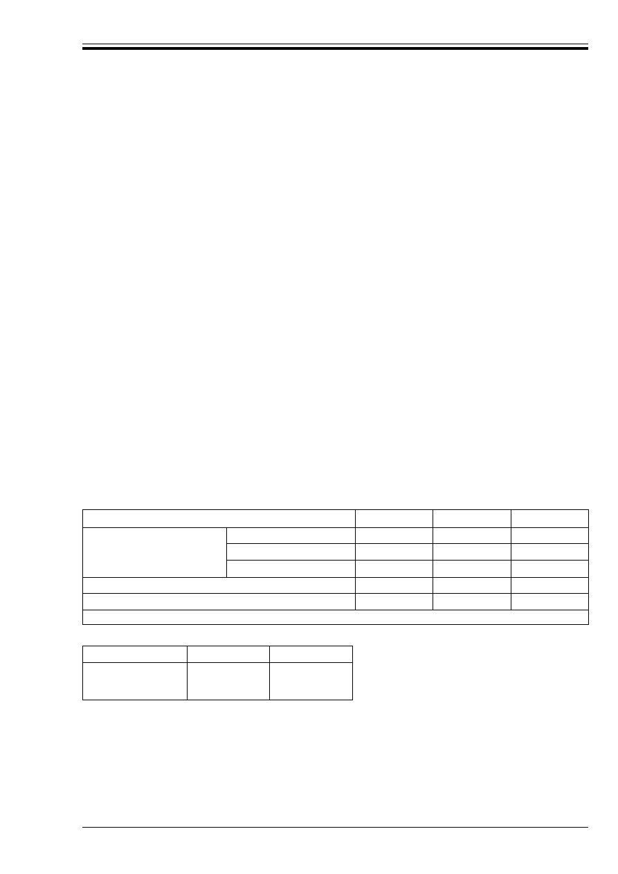
Table 1 — Combination factors
Table 2 — Partial factors
Variable actions
Ò
0
Ò
1
Ò
2
Imposed loads
Dwellings
0.5
0.4
0.2
Offices and stores
0.7
0.6
0.3
Parking
0.7
0.7
0.6
Wind loads
0.7
0.2
0
Snow loads
0.7
0.2
0
NOTE For the purposes of EC2 these three categories of variable actions should be treated as separate and independent actions.
Reference in EC2
Definition
UK values
2.3.3.1(3)
*
G, inf
1.0
*
G, sup
1.35
Licensed copy:Heriot Watt University, 20/04/2004, Uncontrolled Copy, © BSI

DD ENV 1992-1-1:1992
vi
© BSI 12-1999
Table 3 — Values to be used in referenced clauses instead of boxed values
Reference in EC2
Definition
UK values
2.5.1.3(4)
Assumed imperfection v (radians)
when 2nd order effects are insignificant
1/200
2.5.3.5.5(5)
Limits to ratio of support to mid-span moment
where plastic analysis is used
Between 1.0 and 2.0
3.2.5.1(5)
Minimum shear strength of welds
25 % of the tensile strength of the bar
4.1.3.3(8)
Allowance for tolerance (%h) in cover for
precast elements
%h = 5 mm
Allowance for tolerance (%h) in cover for in
situ concrete
%h = 5 mm
4.1.3.3, Table 4.2
and notes
Minimum covers as a function of exposure
See Table 4 of this NAD
4.2.1.3.3(12)
Reduction factor µ to take account of the
effects of long-term loading on maximum
compressive stress (compression zone
decreasing in width)
0.85
4.2.3.4.1(2)
Ratio of long-term relaxation to 1 000 h
relaxation
As Table 4.6 of BS 8110-1:1985
4.3.2.4.4(1)
Limits to cot Ú in the variable strut inclination
method
For all beams (with constant or
curtailed reinforcement)
0.67 < cot Ú < 1.5
4.3.3.1(6)
eqn 4.42
Limits to cot Ú in torsion calculation
0.67 < cot Ú < 1.5
4.3.4.5.2(1)
eqn 4.57
v
Rd2
2.0
(see also 6.4 d) of this NAD)
4.3.5.7(2)
eqn 4.77
Limit to depth of beams
h < 4b
Table 5.1
Minimum diameter of mandrels
See Table 8 of this NAD
5.2.4.1.3(1)
Limiting value of the clear spacing a above
which µ
1
may take a value of 1.0 for
compression and 1.4 for tension
6Ì
Limiting value of b to lapped bar above which
µ
1
may take a value of 1.0 for compression
and 1.4 for tension
2Ì
5.2.5(3)
Extent of bar beyond bend in link
4Ì instead of 5Ì
8Ì instead of 10Ì
5.4.1.2.2(4)
Factor by which minimum spacing should be
reduced under defined circumstances
0.67
In item ii), bar size near lap above which
spacing of transverse steel should be reduced
20 mm
5.4.3.2.1(4)
Maximum bar spacing in slab
Principal and secondary
reinforcement 3h 8 500 mm
5.4.3.3(2)
Minimum shear reinforcement in slabs as a
percentage of the value for beams
100 %
5.4.8.1(3)
Factor defining maximum local stress under a
concentrated load
See note below
6.2.2(1)
Tolerances
See 6.6 of this NAD
NOTE Equation 5.22 should read:
F
Rdu
= A
co
af
cd
ß(A
c1
/A
c0
) 8 3.3af
cd
A
co
where
µ is as defined in 4.2.1.3.3 (11) of EC2
Licensed copy:Heriot Watt University, 20/04/2004, Uncontrolled Copy, © BSI

DD ENV 1992-1-1:1992
© BSI 12-1999
vii
4 Loading codes
The loading codes to be used are:
BS 648:1964, Schedule of weights of building materials.
BS 6399, Loading for buildings.
BS 6399-1:1984, Code of practice for dead and imposed loads.
BS 6399-3:1988, Code of practice for imposed roof loads.
CP 3, Code of basic data for the design of buildings.
CP 3:Chapter V, Loading.
CP 3:Chapter V-2:1972, Wind loads.
In using the above documents with EC2 the following modifications should be noted.
a) The imposed floor loads of a building should be treated as one variable action to which the reduction
factors given in BS 6399-1:1984 are applicable.
b) Snow drift loads obtained from BS 6399-3:1988 should not be treated as accidental actions as defined
in EC2. They should be multiplied by 0.7 and treated as a variable action.
c) The wind loading should be taken as 90 % of the value obtained from CP 3:Chapter V-2:1972.
5 Reference standards
Standards including materials specifications and standards for construction are listed for reference in
Table 4 of this NAD.
Table 4 — References in EC2 to other publications
Reference in EC2
Document
referred to Document title or subject area
Status
UK document
1.1.1P(4)
Eurocode 8
Design of structures in seismic
regions
Draft
—
1.1.1P(5)
Eurocode 1
Actions on structures
Partially
drafted
BS 6399-1 and BS 6399-3
CP3:Chapter V-2
1.1.3P(2)
EC2-1A
Plain or lightly reinforced concrete
structures
1st draft
3.8.1.4 and 3.9.4 of BS 8110-1:1985
1.1.3P(2)
EC2-1B
Precast concrete structures
1st draft
Section 5 of BS 8110-1:1985
1.1.3P(2)
EC2-1C
The use of lightweight aggregate
concrete
1st draft
Section 5 of BS 8110-2:1985
1.1.3P(2)
EC2-1D
The use of unbonded and external
prestressing tendons
1st draft
Section 4 of BS 8110-1:1985 (See note 1)
1.1.3P(2)
EC2-1E
Fatigue requirements
No draft
BS 8110
BS 5400-10 (See note 3)
1.1.3P(2)
EC2-2
Reinforced and prestressed
concrete bridges
Work in
progress
BS 5400-4
1.1.3P(2)
EC2-3
Concrete foundations and piling
Work not
started
BS 8004
1.1.3P(2)
EC2-4
Liquid-retaining structures now
renamed Retaining and
containment structures
Work not
started
BS 8007
1.1.3P(2)
EC2-5
Temporary structures, structures
having a short design life
Work not
started
—
1.1.3P(2)
EC2-6
Massive civil engineering
structures
Work not
started
—
1.1.3P(2)
EC2-10
Fire resistance of concrete
structures
Work in
progress
3.3.6 of BS 8110-1:1985
Section 4 of BS 8110-2:1985
1.4.1
ISO 8930
General principles on reliability of
structures
Published
1987
BS 6100
ISO 6707-1
Building and civil engineering —
General vocabulary — Part 1
Published
1989
BS 6100
1.5
ISO 1000
SI Units and recommendations for
the use of their multiples and of
certain other units
Published
1981
BS 5555
Licensed copy:Heriot Watt University, 20/04/2004, Uncontrolled Copy, © BSI

DD ENV 1992-1-1:1992
viii
© BSI 12-1999
Table 4 — References in EC2 to other publications
Reference in EC2
Document
referred to
Document title or subject
area
Status
UK document
3.1.1P(1)
ENV 206 and
Annex
Concrete-performance,
production, placing and
compliance criteria
Published
1989
BS 5328-1, BS 5328-2, BS 5328-3 and
BS 5328-4.
3.3.5 and section 6 of
BS 8110-1:1985 (See note 3)
3.1.1(4)
5.2 of
ENV 206
Air content limits
Published
1989
6.2.3.2 of BS 8110-1:1985
3.1.2.1
7.3.2 of ENV 206
Density classes of concrete
Published
1989
6.3.5.3 of BS 8110-1:1985
3.1.2.2(2)
7.3.1.1 of ENV 206 Tests for compressive strength
Published
1989
BS 1881-108, BS 1881-110,
BS 1881-111 and BS 1881-116
BS 5328-1 and BS 5328-2
3.1.2.3P(2)
7.3.1.2 of ENV 206 Tensile strength
Published
1989
BS 1881-118
BS 5328-1 and BS 5328-2
3.1.2.4(2)
7.3.1.1 and 11.3.5.4
of ENV 206
Strength classes
Published
1989
BS 5328-1
3.1.2.5.5(4)
7.2.1 of
ENV 206
Consistency of wet concrete
Published
1989
BS 1881-102
BS 5328-1 and BS 5328-4
3.2.1(3)
prEN 10080
Standard for reinforcement
prEN subject
to CEN
enquiry
BS 4449, BS 4482 and BS 4483
3.2.1P(5)
Relevant standards Strength and geometrical
properties of bar tolerances on
cross-sectioned area.
Dimensional requirements for
welded mesh ratio f
y
/f
yk
—
BS 4449, BS 4482 and BS 4483
3.2.4.2P(1)
Relevant standards Ductility and elongation
requirements
—
Clause 10 of BS 4449:1988 and 12.1.3
of BS 4482:1985
3.2.4.4P(1)
Relevant standards Fatigue requirements for
reinforcement
—
Clause 11 and Appendix D of
BS 4449:1988
3.3 and throughout
prEN 10138-1 to
prEN 10138-5
Relevant standards
Prestressing steel
Out for public
comment
BS 5896, BS 4486 and BS 4756
3.4
Relevant standards
European Approval
Documents
Anchorages
—
BS 4447
4.1.2.1
Appropriate
international or
national codes
Actions on structures EC1
Being drafted See clause 4 of this NAD
4.1.3.3 and Table 4.1 ISO/DP 9690
Classification of environmental
conditions for concrete
structures
—
—
4.2.3.4.1
Relevant standards Relaxation of prestressing steel
—
BS 5896, BS 4486 and BS 4756
4.4.3.1(4)
ISO 4356
Basis for the design of structures
— Deformation of buildings at
the serviceability limit states
Published
Accepted by
UK
3.2.1 and 3.2.2 of BS 8110-2:1985
6.3.2.2
Appropriate
national or
international
documents
Specification of finishes
—
6.10 of BS 8110-1:1985
Licensed copy:Heriot Watt University, 20/04/2004, Uncontrolled Copy, © BSI

DD ENV 1992-1-1:1992
© BSI 12-1999
ix
Table 4 — References in EC2 to other publications
6 Additional recommendations
6.1 Chapter 1. Scope
a) Clause 1.1.2, item P(5)
Resistance to fire should be in accordance with BS 8110-2:1985.
6.2 Chapter 2. Basis of design
a) Clause 2.3.2.3(4)
Item (4) applies to all permanent actions.
b) Clause 2.3.3, Table 2.2
It should be assumed that the favourable effects are ¾
F, inf
and that the unfavourable effects are ¾
F, sup.
Footnote
*)
and 2.3.3.1(3) need not be taken into account since the boxed values given in Table 2 of this
NAD are the same as those given in Table 2.2 of EC2.
In footnote
***)
the relevant clause is 2.5.4.4.3(3).
c) Clause 2.3.3.1
In addition to item b), the partial safety factor ¾
Q
for earth and water pressures should be 1.35 and the
recommendations given in clause 2.4.3.1.2 of BS 8110-1:1985 should be followed.
d) Clause 2.3.3.1(8)
In the expressions 2.8(a) and 2.8(b), the boxed figures represent ¾
Q
values.
When using the expression 2.8(b) for independent variable actions, the loading represented by the
expression 2.8(a) should also be considered for each independent action.
Reference in EC2
Document referred to
Document title or
subject area
Status
UK document
6.3.3.1
Relevant Euronorms or
CEN, ISO or national
standards, National
Building Regulations
Control Authority
Requirements for reinforcing
steel
—
BS 4449, BS 4482 and BS 4483
6.3.3.2P(3)
Appropriate
international or national
standards
Cutting and bending of
reinforcement
—
BS 4466
6.3.3.3P(4)
Relevant standards
Fatigue requirements for
welding of reinforcement
—
BS 5400-10 (See note 2)
6.3.3.3P(5)
International or national
standards
Production and checking of
welded connections
—
BS 7123
6.3.3.4P(5)
Standards or approval
documents
Mechanical connectors
—
3.12.8.16 of BS 8110-1:1985
(See note 4)
6.3.4.6.2P(4)
See EN 447
Types of cement for grouting
—
BS 12
7.2.1
Eurocode I
Required level of quality control Work in
progress
6.4 and sections 7 and 8 of
BS 8110-1:1985
BS 5328-1 and BS 5328-4
7.5
CEC or National
Administrative
Procedures
Control of design
—
Building Regulations
7.6.5.1P(6)
Relevant technical
documents
All other structural materials
Other
Eurocodes
—
NOTE 1 Unbonded tendons are not treated in any depth in BS 8110 but EC2 Section 4 applies.
NOTE 2 It is assumed that fatigue will not be a problem in buildings and hence BS 8110 does not give any rules.
NOTE 3 The exposure conditions referred to in 4.1.3.3 are related to exposure to chemically aggressive environments
(e.g. industrial pollutants) not normal environments. There is no UK equivalent document.
NOTE 4 Clause 3.12.8.16 of BS 8110-1:1985 on butt joints gives rules for the use of both tension and compression couplers.
BS 8110-1:1985 Clause 3.12.8.16.2 gives performance criteria for tension couplers.
Licensed copy:Heriot Watt University, 20/04/2004, Uncontrolled Copy, © BSI

DD ENV 1992-1-1:1992
x
© BSI 12-1999
e) Clause 2.5.1.2
Normally it will be sufficient to consider the combination of dead, imposed and wind loads, without
patterning the imposed loads, i.e. expression 2.8 b) in 2.3.3.1(8) may be used. However, load patterning
may need to be considered in sensitive structures.
6.3 Chapter 3. Material properties
a) Clause 3.2
Current British Standards for reinforcement are BS 4449:1988 (bars) and BS 4483:1985 (welded
fabric). It is envisaged that when EN 10080 (currently in draft form as prEN 10080) is published
Grade 500 (bars and fabric) will supersede Grade 460.
The differences between the current British Standards and prEN 10080 are summarized in Table 5.
6.4 Chapter 4. Section and member design
a) Clause 4.1.3.3(5)
Item (5) should be replaced by the following:
“(5) The specified nominal cover to all reinforcement should be not less than the size of the main bar or,
where bars are in pairs or bundles, the size of a single bar of the cross-sectional area equal to the sum of
their cross-sectional areas. It should be not less than the nominal maximum size of the aggregate.”
b) Clause 4.1.3.3(6)
The specified nominal cover required for reinforcement, including links, to ensure adequate durability
should be in accordance with Table 6 of this NAD. To conform with current UK practice, Table 6 gives
nominal values of cover, which include allowance for the tolerance of 5 mm.
c) Table 4.8
The maximum value of f
ck
in the determination of E
Rd
should be taken as 40 N/mm
2
(strength
class C40/50).
d) Clause 4.3.4.5.2(1)
In equation 4.57, in addition to the limitation on v
Rd2
given in Table 3 of this NAD the shear stress at
the perimeter of the column should not exceed 0.9 ßf
ck
Equation 4.58 is applicable where v
Rd3
u 1.6v
Rd1 ·
Where 1.6v
Rd1
< v
Rd3
u 2.0v
Rd1
equation 4.58a below
should be used:
v
Rd3
= 1.4v
Rd1
+ (0.3CA
sw
f
ya
sin µ)/u (4.58a)
e) Clause 4.4.3.2(5)
At the end of c) the following sentence should be added:
““Nominally reinforced” values to correspond to Ô = 0.15 %.”
f) Table 4.14
Table 4.14 should be replaced by Table 7 of this NAD.
Licensed copy:Heriot Watt University, 20/04/2004, Uncontrolled Copy, © BSI

DD ENV 1992-1-1:1992
© BSI 12-1999
xi
Table 5 — Differences between current British Standards and prEN 10080
Table 6 — Cover requirements for normal weight concrete
Table 7 — Basic ratios of span/effective depth for reinforced concrete members
without axial compression
Property
BS 4449 and BS 4483
prEN 10080
Specified characteristic yield
strength
Grade 460 N/mm
2
Grade 250 N/mm
2
500 N/mm
2
not included
Bond strength for:
Ribbed bars/wires
Indented wires
Plain bars/wires
Deformed Type 2
Deformed Type 1
Plain rounds
High bond
Not included
Not included
Ductility class (now defined as
elongation at maximum load and
ultimate to yield strength ratio)
Not covered
Class H or Class N (this may be
deleted in the final version) (see note)
NOTE All ribbed bars and all Grade 250 bars may be assumed to be Class H. Ribbed wire welded fabric may be assumed to be
available in Class H in wire sizes of 6 mm or over. Plain or indented wire welded fabric may be assumed to be available in Class N.
In design where plastic analysis or moment distribution over 15 % is used, it is essential to specify ductility class (H) as defined in
prEN 10080 since this parameter is not covered by BS 4449 and BS 4483.
Exposure class, according to Table 4.1
1
2a
2b
3
4a
4b
5a
5b
5c
Reinforcement
Nominal
a
Minimum
20
(15)
35
(30)
35
(30)
40
(35)
40
(35)
40
(35)
35
(30)
35
(30)
45
(40)
Prestressing
Nominal
a
Minimum
25
(20)
40
(35)
40
(35)
45
(40)
45
(40)
45
(40)
40
(35)
40
(35)
50
(45)
NOTE 1 In order to satisfy the provisions of 4.1.3.3P(3) these values for cover should be associated with particular concrete
qualities, to be determined from Table 3 of ENV 206 and its National Annex.
NOTE 2 A reduction of 5 mm may be made where concrete of strength class C40/50 and above is used for reinforced concrete in
exposure classes 2a to 5b, and for prestressed concrete in exposure classes 2a to 5b. For slab elements, a further reduction of 5 mm
may be made for exposure classes 2 to 5.
NOTE 3 For exposure class 5c, a protective barrier should be provided to prevent direct contact with aggressive media.
a
The nominal values for cover have been obtained from the minimum values by allowing for a negative construction tolerance
of 5 mm.
Structural system
Concrete
highly
stressed
Concrete
lightly
stressed
Concrete
nominally
reinforced
1. Simply supported beam, one or two-way spanning simply
supported slab
18
25
34
2. End span of continuous beam or one-way continuous slab
or two-way spanning slab continuous over one long side
23
32
44
3. Interior span of beam or one-way or two-way spanning slab 25
35
38
4. Slab supported on columns without beams (Flat slab),
based on longer span
21
30
41
5. Cantilever
7
10
14
NOTE 1 See also 6.4 e) of this NAD.
NOTE 2 4.4.3.2(4) of EC2 should not be applied to the basic span/effective depth ratios for nominally reinforced concrete.
Licensed copy:Heriot Watt University, 20/04/2004, Uncontrolled Copy, © BSI

DD ENV 1992-1-1:1992
xii
© BSI 12-1999
6.5 Chapter 5. Detailing provisions
a) Table 5.1
Table 5.1 should be replaced by Table 8 of this NAD which gives minimum diameters of mandrels.
b) Clause 5.2.4.1.2
This clause should be interpreted as applying to laps in reinforcement in beams only.
c) Clause 5.4.2.1.4(3)
When using equation 5.4 within this clause [see 5.2.3.4.1(1)] A
s,req
should be at least one-quarter of the
area of the tension reinforcement in the span [see 5.4.2.1.4(1)].
d) Clause 5.4.2.4(2)
This reinforcement should be placed inside the stirrups.
e) Clause 5.4.3.2.3
When corner reinforcement is required, the conditions in 3.5.3.5, 3.5.3.6 and 3.5.3.7 of BS 8110-1:1985
should be used.
f) Clause 5.4.3.3(4)
Longitudinal spacing of successive links should not exceed 0.75d.
g) Clause 5.5.2
The provision of ties should be based on 2.4.3.2, 3.12.3 and 5.1.8 of BS 8110-1:1985 and 2.6 of
BS 8110-2:1985.
6.6 Chapter 6. Construction and workmanship
a) Clause 6.2
Tolerances in this clause should be read as dimensional deviations and should be based on those given
in 6.11, 7.3 and 8.6 of BS 8110-1:1985.
b) Clause 6.3.3.3
Additional guidance is given in 3.12.8.16.1, 3.12.8.16.2, 3.12.8.17, 3.12.8.18 and 7.6 of BS 8110-1:1985.
Table 8 — Minimum diameters of mandrels
Hooks, bends, loops
(see Figure 5.2 of EC2)
Bent-up bars or other curved bars
Bar diameter
Value of minimum concrete cover,
perpendicular to plane of curvature
Ì < 20 mm
Ì
W 20 mm
> 100 mm
and > 7Ì
> 50 mm
and > 3Ì
u 50 mm
and u 3Ì
Minimum diameter of mandrels
for plain bars S250
4Ì
4Ì
7Ì
8.5Ì
11.4Ì
Minimum diameter of mandrels
for high bond bars S460
6Ì
8Ì
13Ì
15.7Ì
20.9Ì
Licensed copy:Heriot Watt University, 20/04/2004, Uncontrolled Copy, © BSI

DD ENV 1992-1-1:1992
© BSI 12-1999
xiii
List of references
(see clause 2)
Normative references
BSI standards publications
BRITISH STANDARDS INSTITUTION, London
BS 648:1964, Schedule of weights of building materials.
BS 6399, Loading for buildings.
BS 6399-1:1984, Code of practice for dead and imposed loads.
BS 6399-3:1988, Code of practice for imposed roof loads.
BS 8110, Structural use of concrete.
BS 8110-1:1985, Code of practice for design and construction.
BS 8110-2:1985, Code of practice for special circumstances.
CP3, Code of basic data for the design of buildings.
CP3:Chapter V, Loading.
CP3:Chapter V-2, Wind loads.
Informative references
BSI standards publications
BRITISH STANDARDS INSTITUTION, London
BS 12:1991, Specification for Portland cement.
BS 1881, Testing concrete.
BS 1881-102:1983, Method for determination of slump.
BS 1881-108:1983, Method for making test cubes from fresh concrete.
BS 1881-110:1983, Method for making test cylinders from fresh concrete.
BS 1881-111:1983, Method of normal curing of test specimens (room temperature).
BS 1881-116:1983, Method for determination of compressive strength of concrete cubes.
BS 1881-118:1983, Method for determination of flexural strength.
BS 4447:1973, Specification for the performance of prestressing anchorages for post-tensioned construction.
BS 4449:1988, Specification for carbon steel bars for the reinforcement of concrete.
BS 4466:1989, Specification for scheduling, dimensioning, bending and cutting of steel reinforcement for
concrete.
BS 4482:1985, Specification for cold reduced steel wire for the reinforcement of concrete.
BS 4483:1985, Specification for steel fabric for the reinforcement of concrete.
BS 4486:1990, Specification for hot rolled and hot rolled and processed high tensile alloy steel bars for the
prestressing of concrete.
BS 4756:1971, Specification for ready mixed aluminium priming paints for woodwork.
BS 5328, Concrete.
BS 5328-1:1991, Guide to specifying concrete.
BS 5328-2:1991, Methods for specifying concrete mixes.
BS 5328-3:1990, Specification for the procedures to be used in producing and transporting concrete.
BS 5328-4:1990, Specification for the procedures to be used in sampling, testing and assessing compliance
of concrete.
BS 5400, Steel, concrete and composite bridges.
BS 5555:1978, Specification for SI units and recommendations for the use of their multiples and of certain
other units.
BS 5896:1980, Specification for high tensile steel wire and strand for the prestressing of concrete.
Licensed copy:Heriot Watt University, 20/04/2004, Uncontrolled Copy, © BSI

DD ENV 1992-1-1:1992
© BSI 12-1999
xiv
BS 6100, Glossary of building and civil engineering terms.
BS 7123:1989, Specification for metal arc welding of steel for concrete reinforcement.
BS 8004:1986, Code of practice for foundations.
BS 8007:1987, Code of practice for design of concrete structures for retaining aqueous liquids.
CEN and CENELEC standards publications
EUROPEAN COMMITTEE FOR STANDARDIZATION (CEN) and EUROPEAN COMMITTEE FOR ELECTROTECHNICAL
STANDARDIZATION (CENELEC), Brussels. (All publications are available from BSI Sales.)
ENV 206, Concrete — Performance, production, placing and compliance criteria.
prEN 10080, Steel for the reinforcement of concrete weldable ribbed reinforcing steel B 500 — Technical
delivery conditions for bars, coils and welded fabric.
Licensed copy:Heriot Watt University, 20/04/2004, Uncontrolled Copy, © BSI

EUROPEAN PRESTANDARD
PRÉNORME EUROPÉENNE
EUROPÄISCHE VORNORM
ENV 1992-1-1
December 1991
UDC 624.92.012.3/.4:624.07
Descriptors: Buildings, concrete structure, computation, building codes, rules of calculation
English version
Eurocode 2: Design of concrete structures —
Part 1: General rules and rules for buildings
Eurocode 2: Calcul des structures en béton —
Partie 1: Règles générales et règles pour les
bâtiments
Eurocode 2: Planung von Stahlbeton- und
Spannbetontragwerken — Teil 1: Grundlagen
und Anwendungsregeln für den Hochbau
This European Prestandard (ENV) was approved by CEN on 1991-12-27 as a
prospective standard for provisional application. The period of validity of this
ENV is limited initially to three years. After two years the members of CEN
will be requested to submit their comments, particularly on the question
whether the ENV can be converted into a European Standard (EN).
CEN members are required to announce the existence of this ENV in the same
way as for an EN and to make the ENV available promptly at national level in
an appropriate form. It is permissible to keep conflicting national standards in
force (in parallel to the ENV) until the final decision about the possible
conversion of the ENV into an EN is reached.
CEN members are the national standards bodies of Austria, Belgium,
Denmark, Finland, France, Germany, Greece, Iceland, Ireland, Italy,
Luxembourg, Netherlands, Norway, Portugal, Spain, Sweden, Switzerland and
United Kingdom.
CEN
European Committee for Standardization
Comité Européen de Normalisation
Europäisches Komitee für Normung
Central Secretariat: rue de Stassart 36, B-1050 Brussels
© CEN 1991 copyright reserved to all CEN members
Ref. No. ENV 1992-1-1:1991 E
Licensed copy:Heriot Watt University, 20/04/2004, Uncontrolled Copy, © BSI

ENV 1992-1-1:1992
© BSI 12-1999
2
Foreword
0.1 Objectives of the Eurocodes
1) The Structural Eurocodes comprise a group of
standards for the structural and geotechnical
design of buildings and civil engineering works.
2) They are intended to serve as reference
documents for the following purposes:
a) As a means to prove compliance of building
and civil engineering works with the essential
requirements of the Construction Products
Directive (CPD)
b) As a framework for drawing up harmonised
technical specifications for construction
products.
3) They cover execution and control only to the
extent that is necessary to indicate the quality of
the construction products, and the standard of
the workmanship, needed to comply with the
assumptions of the design rules.
4) Until the necessary set of harmonised
technical specifications for products and for
methods of testing their performance is available,
some of the Structural Eurocodes cover some of
these aspects in informative annexes.
0.2 Background to the Eurocode programme
1) The Commission of the European
Communities (CEC) initiated the work of
establishing a set of harmonised technical rules
for the design of building and civil engineering
works which would initially serve as an
alternative to the different rules in force in the
various Member States and would ultimately
replace them. These technical rules became
known as the “Structural Eurocodes”.
2) In 1990, after consulting their respective
Member States, the CEC transferred work of
further development, issue and updates of the
Structural Eurocodes to CEN and the EFTA
Secretariat agreed to support the CEN work.
3) CEN Technical Committee CEN/TC 250 is
responsible for all Structural Eurocodes.
0.3 Eurocode programme
1) Work is in hand on the following Structural
Eurocodes, each generally consisting of a number
of parts:
2) Separate sub-committees have been formed by
CEN/TC 250 for the various Eurocodes listed
above.
3) This part of the Structural Eurocode for Design
of Concrete Structures, which had been finalised
and approved for publication under the direction
of CEC, is being issued by CEN as a European
Prestandard (ENV) with an initial life of three
years.
4) This Prestandard is intended for experimental
practical application in the design of the building
and civil engineering works covered by the scope
as given in 1.1.2 and for the submission of
comments.
5) After approximately two years CEN members
will be invited to submit formal comments to be
taken into account in determining future action.
6) Meanwhile, feedback and comments on this
Prestandard should be sent to the Secretariat of
sub-committee CEN/TC 250/SC 2 at the following
address:
DIN
Burggrafenstrasse 6
D-1000 Berlin 30
GERMANY
or to your national standards organization.
0.4 National Application Documents
1) In view of the responsibilities of authorities in
member countries for the safety, health and other
matters covered by the essential requirements of
the CPD, certain safety elements in this ENV
have been assigned indicative values which are
identified by |______|. The authorities in each
member country are expected to assign definitive
values to these safety elements.
EN 1991 Eurocode 1 Basis of design and
actions on structures
EN 1992 Eurocode 2 Design of concrete
structures
EN 1993 Eurocode 3 Design of steel
structures
EN 1994 Eurocode 4 Design of composite steel
and concrete structures
EN 1995 Eurocode 5 Design of timber
structures
EN 1996 Eurocode 6 Design of masonry
structures
EN 1997 Eurocode 7 Geotechnical design
EN 1998 Eurocode 8 Design provisions for
earthquake resistance of
structures
In addition the following may be added to the
programme:
EN 1999 Eurocode 9 Design of aluminium
structures
Licensed copy:Heriot Watt University, 20/04/2004, Uncontrolled Copy, © BSI

ENV 1992-1-1:1992
© BSI 12-1999
3
2) Many of the harmonised supporting standards,
including the Eurocodes giving values for actions
to be taken into account and measures required
for fire protection, will not be available by the
time this Prestandard is issued. It is therefore
anticipated that a National Application
Document (NAD) giving definitive values for
safety elements, referencing compatible
supporting standards and providing national
guidance on the application of this Prestandard,
will be issued by each member country or its
Standards Organisation.
3) It is intended that this Prestandard is used in
conjunction with the NAD valid in the country
where the building or civil engineering works are
located.
0.5 Matters specific to this Prestandard
1) The scope of Eurocode 2 is defined in 1.1.1 and
the scope of this Part of Eurocode 2 is defined
in 1.1.2. Additional Parts of Eurocode 2 which are
planned are indicated in 1.1.3; these will cover
additional technologies or applications, and will
complement and supplement this Part.
2) In using this Prestandard in practice,
particular regard should be paid to the
underlying assumptions and conditions given
in 1.3.
3) The seven chapters of this Prestandard are
complemented by four Appendices which have
the same normative status as the chapters to
which they relate. These Appendices have been
introduced by moving some of the more detailed
principles/Application Rules, which are needed in
particular cases, out of the main part of the text
to aid its clarity.
4) As indicated in 0.4 2) of this Foreword,
reference should be made to National Application
Documents which will give details of compatible
supporting standards to be used. For this Part of
Eurocode 2, particular attention is drawn to the
approved Prestandard ENV 206 (Concrete —
performance, production, placing and compliance
criteria), and the durability requirements given
in 4.1 of this Prestandard.
5) The provisions of this Prestandard are based
substantially on the 1978 edition of the CEB
Model Code and other more recent CEB and FIP
documents.
6) In developing this Prestandard, background
documents have been prepared, which give
commentaries on and justifications for some of
the provisions in this Prestandard.
Licensed copy:Heriot Watt University, 20/04/2004, Uncontrolled Copy, © BSI

ENV 1992-1-1:1992
4
© BSI 12-1999
Contents
Page
Foreword
2
1
Introduction
11
1.1
Scope
11
1.1.1
Scope of Eurocode 2
11
1.1.2
Scope of Part 1 of Eurocode 2
11
1.1.3
Further parts of Eurocode 2
12
1.2
Distinction between principles
and application rules
12
1.3
Assumptions
12
1.4
Definitions
13
1.4.1
Terms common to all Eurocodes
13
1.4.2
Special terms used in Part 1
of Eurocode 2
13
1.5
S.I. units
15
1.6
Symbols common to all Eurocodes
15
1.6.1
Latin upper case letters
15
1.6.2
Latin lower case letters
15
1.6.3
Greek lower case letters
16
1.6.4
Subscripts
16
1.7
Special symbols used in this
Part 1 of Eurocode 2
17
1.7.1
General
17
1.7.2
Latin upper case symbols
18
1.7.3
Latin lower case symbols
18
1.7.4
Greek symbols
19
2
Basis of design
20
2.0
Notation — Sections 2.1 – 2.4
20
2.1
Fundamental requirements
21
2.2
Definitions and classifications
21
2.2.1
Limit states and design situations
21
2.2.1.1 Limit states
21
2.2.1.2 Design situations
22
2.2.2
Actions
22
2.2.2.1 Definitions and principal
classifications
22
2.2.2.2 Characteristic values of actions
22
2.2.2.3 Representative values of
variable actions
23
2.2.2.4 Design values of actions
23
2.2.2.5 Design values of the effects
of actions
24
2.2.3
Material properties
24
2.2.3.1 Characteristic values
24
2.2.3.2 Design values
24
Page
2.2.4
Geometrical data
24
2.2.5
Load arrangements and load cases
25
2.3
Design requirements
25
2.3.1
General
25
2.3.2
Ultimate limit states
25
2.3.2.1 Verification conditions
25
2.3.2.2 Combination of actions
25
2.3.2.3 Design values of permanent actions
26
2.3.3
Partial safety factors for
ultimate limit states
27
2.3.3.1 Partial safety factors for actions
on building structures
27
2.3.3.2 Partial safety factors for materials
28
2.3.4
Serviceability limit states
28
2.4
Durability
29
2.5
Analysis
29
2.5.1
General provisions
29
2.5.1.0 Notation
29
2.5.1.1 General
29
2.5.1.2 Load cases and combinations
30
2.5.1.3 Imperfections
30
2.5.1.4 Second order effects
32
2.5.1.5 Time dependent effects
32
2.5.1.6 Design by testing
32
2.5.2
Idealisation of the structure
32
2.5.2.0 Notation
32
2.5.2.1 Structural models for overall
analysis
32
2.5.2.2 Geometrical data
33
2.5.3
Calculation methods
36
2.5.3.0 Notation
36
2.5.3.1 Basic considerations
36
2.5.3.2 Types of structural analysis
36
2.5.3.3 Simplifications
37
2.5.3.4 Structural analysis of beams
and frames
37
2.5.3.5 Analysis of slabs
38
2.5.3.6 Structural analysis of walls and
plates loaded in their own plane
39
2.5.3.7 Corbels, deep beams and
anchorage zones for
post-tensioning forces
40
2.5.4
Determination of the effects of
prestressing
41
2.5.4.0 Notation
41
Licensed copy:Heriot Watt University, 20/04/2004, Uncontrolled Copy, © BSI

ENV 1992-1-1:1992
© BSI 12-1999
5
Page
2.5.4.1 General
42
2.5.4.2 Determination of prestressing force
42
2.5.4.3 Effects of prestressing under
service conditions
43
2.5.4.4 Effects of prestressing at the
ultimate limit states
43
2.5.5
Determination of the effects
of time dependent deformation
of concrete
44
2.5.5.0 Notation
44
2.5.5.1 General
44
3
Material properties
45
3.1
Concrete
45
3.1.0
Notation
45
3.1.1
General
46
3.1.2
Normal weight concrete
46
3.1.2.1 Definitions
46
3.1.2.2 Compressive strength of concrete
46
3.1.2.3 Tensile strength
46
3.1.2.4 Strength classes of concrete
47
3.1.2.5 Deformation properties
47
3.2
Reinforcing steel
50
3.2.0
Notation
50
3.2.1
General
50
3.2.2
Classification and geometry
50
3.2.3
Physical properties
51
3.2.4
Mechanical properties
51
3.2.4.1 Strength
51
3.2.4.2 Ductility characteristics
51
3.2.4.3 Modulus of elasticity
51
3.2.4.4 Fatigue
51
3.2.5
Technological properties
52
3.2.5.1 Bond and anchorage
52
3.2.5.2 Weldability
52
3.3
Prestressing steel
53
3.3.0
Notation
53
3.3.1
General
53
3.3.2
Classification and geometry
53
3.3.3
Physical properties
54
3.3.4
Mechanical properties
54
3.3.4.1 Strength
54
3.3.4.2 Stress-strain diagram
54
3.3.4.3 Ductility characteristics
54
3.3.4.4 Modulus of elasticity
55
3.3.4.5 Fatigue
55
Page
3.3.4.6 Multi-axial stresses
55
3.3.5
Technological properties
55
3.3.5.1 Surface condition
55
3.3.5.2 Relaxation
55
3.3.5.3 Susceptibility to stress-corrosion
55
3.4
Prestressing devices
55
3.4.1
Anchorages and couplers
55
3.4.1.1 General
55
3.4.1.2 Mechanical properties
56
3.4.2
Ducts and sheaths
56
3.4.2.1 General
56
4
Section and member design
56
4.1
Durability requirements
57
4.1.0
Notation
57
4.1.1
General
57
4.1.2
Actions
57
4.1.2.1 General
57
4.1.2.2 Environmental conditions
57
4.1.2.3 Chemical attack
57
4.1.2.4 Physical attack
58
4.1.2.5 Consequential indirect effects
58
4.1.3
Design
58
4.1.3.1 General
58
4.1.3.2 Design criteria
59
4.1.3.3 Concrete cover
59
4.1.4
Materials
61
4.1.5
Construction
61
4.2
Design data
61
4.2.1
Concrete
61
4.2.1.0 Notation
61
4.2.1.1 General
62
4.2.1.2 Physical properties
62
4.2.1.3 Mechanical properties
62
4.2.1.4 Time-dependent behaviour
65
4.2.2
Reinforced concrete
66
4.2.2.0 Notation
66
4.2.2.1 Reinforcing steel: general
66
4.2.2.2 Physical properties of
reinforcing steel
66
4.2.2.3 Mechanical properties of
reinforcing steel
66
4.2.2.4 Technological properties of
reinforcing steel
67
4.2.3
Prestressed concrete
67
4.2.3.0 Notation
67
Licensed copy:Heriot Watt University, 20/04/2004, Uncontrolled Copy, © BSI

ENV 1992-1-1:1992
6
© BSI 12-1999
Page
4.2.3.1 Prestressing steel: general
68
4.2.3.2 Physical properties of
prestressing steel
68
4.2.3.3 Mechanical properties of
prestressing steel
68
4.2.3.4 Technological properties of
prestressing steel
70
4.2.3.5 Design of members in
prestressed concrete
71
4.3
Ultimate limit states
78
4.3.1
Ultimate limit states for
bending and longitudinal force
78
4.3.1.0 Notation
78
4.3.1.1 General
78
4.3.1.2 Design resistance moments
of beams subject to bending
and longitudinal force
78
4.3.1.3 Brittle failure and hyperstrength
79
4.3.2
Shear
80
4.3.2.0 Notation
80
4.3.2.1 General
81
4.3.2.2 Design method for shear
81
4.3.2.3 Elements not requiring
design shear reinforcement
83
4.3.2.4 Elements requiring design
shear reinforcement
84
4.3.2.5 Shear between web and flanges
87
4.3.3
Torsion
88
4.3.3.0 Notation
88
4.3.3.1 Pure torsion
88
4.3.3.2 Combined effects of actions
91
4.3.3.3 Warping torsion
91
4.3.4
Punching
92
4.3.4.0 Notation
92
4.3.4.1 General
92
4.3.4.2 Scope and definitions
93
4.3.4.3 Design method for checking
punching shear
95
4.3.4.4 Slabs with variable depth
97
4.3.4.5 Shear resistance
98
4.3.5
Ultimate limit states
induced by structural
deformation (buckling)
101
4.3.5.0 Notation
101
4.3.5.1 Scope and definitions
101
4.3.5.2 Design procedures
102
Page
4.3.5.3 Classification of structures
and structural elements
102
4.3.5.4 Imperfections
105
4.3.5.5 Specific data for different types
of structure
105
4.3.5.6 Simplified design methods for
isolated columns
107
4.3.5.7 Lateral buckling of slender beams
111
4.4
Serviceability limit states
112
4.4.0
General
112
4.4.0.1 Notation
112
4.4.0.2 Scope
113
4.4.1
Limitation of stresses under
serviceability conditions
113
4.4.1.1 Basic considerations
113
4.4.1.2 Methods for checking stresses
113
4.4.2
Limit states of cracking
114
4.4.2.1 General considerations
114
4.4.2.2 Minimum reinforcement areas
115
4.4.2.3 Control of cracking without
direct calculation
116
4.4.2.4 Calculation of crack widths
118
4.4.3
Limit states of deformation
121
4.4.3.1 Basic considerations
121
4.4.3.2 Cases where calculations may
be omitted
122
4.4.3.3 Checking deflections by calculation
123
5
Detailing provisions
123
5.0
Notation
123
5.1
General
124
5.2
Steel for reinforced concrete
124
5.2.1
General detailing arrangements
124
5.2.1.1 Spacing of bars
124
5.2.1.2 Permissible curvatures
125
5.2.2
Bond
125
5.2.2.1 Bond conditions
125
5.2.2.2 Ultimate bond stress
126
5.2.2.3 Basic anchorage length
127
5.2.3
Anchorage
127
5.2.3.1 General
127
5.2.3.2 Anchorage methods
127
5.2.3.3 Transverse reinforcement
parallel to the concrete surface
128
5.2.3.4 Required anchorage length
128
5.2.3.5 Anchorage by mechanical devices
129
Licensed copy:Heriot Watt University, 20/04/2004, Uncontrolled Copy, © BSI

ENV 1992-1-1:1992
© BSI 12-1999
7
Page
5.2.4
Splices
129
5.2.4.1 Lap splices for bars or wires
129
5.2.4.2 Laps for welded mesh fabrics
made of high bond wires
131
5.2.5
Anchorage of links and
shear reinforcement
132
5.2.6
Additional rules for high bond
bars exceeding |32 mm|
in diameter
132
5.2.6.1 Construction details
132
5.2.6.2 Bond
133
5.2.6.3 Anchorages and joints
133
5.2.7
Bundled high bond bars
134
5.2.7.1 General
134
5.2.7.2 Anchorage and joints
134
5.3
Prestressing units
134
5.3.1
Arrangement of the
prestressing units
134
5.3.2
Concrete cover
134
5.3.3
Horizontal and vertical spacing
134
5.3.3.1 Pre-tensioning
134
5.3.3.2 Post-tensioning
135
5.3.4
Anchorages and couplers for
prestressing tendons
135
5.4
Structural members
135
5.4.1
Columns
135
5.4.1.1 Minimum dimensions
135
5.4.1.2 Longitudinal and transverse
reinforcement
136
5.4.2
Beams
136
5.4.2.1 Longitudinal reinforcement
136
5.4.2.2 Shear reinforcement
139
5.4.2 3 Torsional reinforcement
136
5.4.2.4 Surface reinforcement
141
5.4.3
Cast in situ solid slabs
142
5.4.3.1 Minimum thickness
142
5.4.3.2 Flexural reinforcement
142
5.4.3.3 Shear reinforcement
143
5.4.4
Corbels
144
5.4.5
Deep beams
145
5.4.6
Anchorage zones for
post-tensioning forces
145
5.4.7
Reinforced concrete walls
146
5.4.7.1 General
146
5.4.7.2 Vertical reinforcement
146
5.4.7.3 Horizontal reinforcement
146
Page
5.4.7.4 Transverse reinforcement
146
5.4.8
Particular cases
146
5.4.8.1 Concentrated forces
146
5.4.8.2 Forces associated with change
in direction
147
5.4.8.3 Indirect supports
147
5.5
Limitation of damage due to
accidental actions
147
5.5.1
Tying system
147
5.5.2
Proportioning of ties
148
5.5.3
continuity and anchorage
148
6
Construction and workmanship
148
6.1
Objectives
148
6.2
Tolerances
148
6.2.1
Tolerances — General
148
6.2.2
Tolerances with regard to
structural safety
148
6.2.3
Tolerances for concrete cover
149
6.2.4
Tolerances for construction
purposes
149
6.3
Construction rules
149
6.3.1
Concrete
149
6.3.2
Formwork and falsework
149
6.3.2.1 Basic requirements
149
6.3.2.2 Surface finish
150
6.3.2.3 Temporary works inserts
150
6.3.2.4 Removal of formwork and
falsework
150
6.3.3
Reinforcing steel
150
6.3.3.1 Basic requirements
150
6.3.3.2 Transport, storage and fabrication
of the reinforcement
150
6.3.3.3 Welding
151
6.3.3.4 Joints
151
6.3.3.5 Fabrication, assembly and
placing of the reinforcement
151
6.3.4
Prestressing steel
151
6.3.4.1 Basic requirements
151
6.3.4.2 Transport and storage
of the tendons
152
6.3.4.3 Fabrication of tendons
152
6.3.4.4 Placing of the tendons
152
6.3.4.5 Tensioning of the tendons
152
6.3.4.6 Grouting and other protective
measures
153
Licensed copy:Heriot Watt University, 20/04/2004, Uncontrolled Copy, © BSI

ENV 1992-1-1:1992
8
© BSI 12-1999
Page
7
Quality control
155
7.1
Scope and objectives
155
7.2.1
General
155
7.2.2
Internal control
155
7.2.3
External control
155
7.2.4
Conformity control
155
7.3
Verification systems
155
7.4
Control of the different stages
of the building process
155
7.5
Control of design
156
7.6
Control of production and
construction
156
7.6.1
Objectives
156
7.6.2
Objectives of production and
construction control
156
7.6.3
Elements of production and
construction control
157
7.6.4
Initial tests
157
7.6.5
Checks during construction
157
7.6.5.1 General requirements
157
7.6.5.2 Compliance controls at
delivery to the site
157
7.6.5.3 Controls prior to concreting
and during prestressing
158
7.6.6
Conformity controls
158
7.7
Control and maintenance of
the completed structure
158
Appendix 1 Additional provisions for
the determination of the effects of
time-dependent deformation of concrete
159
Appendix 2 Non-linear analysis
162
Appendix 3 Supplementary information
on the ultimate limit states induced by
structural deformations
167
Appendix 4 Checking deflections
by calculation
174
Figure 2.1 — Application of the effective
geometrical imperfections
31
Figure 2.2 — Definition of dimensions
33
Figure 2.3 — Approximate effective spans
for calculation of effective breadth ratios
34
Figure 2.4 — Determination of effective
span (l
eff
) according to Equation (2.15)
for different support conditions
35
Figure 2.5 — Example of a corbel, with a
strut and tie model
41
Figure 3.1 — Stress-strain diagram for
uniaxial compression
48
Page
Figure 3.2 — Typical stress-strain
diagram of reinforcing steel
52
Figure 3.3 — Typical stress-strain
diagram of prestressing steel
54
Figure 4.1 — Schematic stress-strain
diagram for structural
analysis (4.2.1.3.3(5)–(7)]
63
Figure 4.2 — Parabolic — rectangular
stress-strain diagram for concrete
in compression
64
Figure 4.3 — Bi-linear stress-strain
diagram for concrete
65
Figure 4.4 — Rectangular diagram
65
Figure 4.5 — Design stress-strain diagram
for reinforcing steel
67
Figure 4.6 — Design stress-strain diagram
for prestressing steel
69
Figure 4.7 — Example of n
1
/n
2
value in
Table 4.4 (in this case n
1
/n
2
= 7/3)
70
Figure 4.8 — Relaxation losses
after 1 000 h at 20 °C
71
Figure 4.9 a) and b) — Transfer of
prestress in pretensioned elements
75
Figure 4.9 c) — Derivation of Equation (4.14)
77
Figure 4.10 — Dispersion of prestress
77
Figure 4.11 — Strain diagrams in the
ultimate limit state
79
Figure 4.12 — Definition of A
sl
for use in
Equation (4.18)
83
Figure 4.13 — Notation for members
subjected to shear
84
Figure 4.14 — Notation for the
connection between flange and web
88
Figure 4.15 — Notation used in
Section 4.3.3.1
89
Figure 4.16 — Design model for punching
shear at the ultimate limit state
93
Figure 4.17 — Application of punching
provisions in non-standard cases
94
Figure 4.18 — Critical perimeter round
loaded areas located away from an
unsupported edge
94
Figure 4.19 — Critical perimeter near
an opening
95
Figure 4.20 — Critical sections near
unsupported edges
95
Figure 4.21 — Approximate values for "
96
Figure 4.22 — Slab with column heads
where l
H
< 1.5 h
H
97
Licensed copy:Heriot Watt University, 20/04/2004, Uncontrolled Copy, © BSI

ENV 1992-1-1:1992
© BSI 12-1999
9
Page
Figure 4.23 — Slab with enlarged column
head Where l
H
> 1.5 (d + h
H
)
98
Figure 4.24 — Bending moments m
Sdx
and m
Sdy
in slab-column joints subjected to
eccentric loading, and effective width for
resisting these moments
100
Figure 4.25 — Detailing of reinforcement
over edge and corner columns
100
Figure 4.26 — Types of isolated columns
103
Figure 4.27 — Nomograms for the
calculation of the effective length
104
Figure 4.28 — Slenderness limits for
isolated members with rigidly or elastically
restrained ends in non-sway structures
106
Figure 4.29 — Design model for the
calculation of the total eccentricity
107
Figure 4.30 — Model column (notation)
108
Figure 4.31 — Assumption for separate
checks in the two principal planes
110
Figure 4.32 — Separate check in
the y-direction if e
z
> 0.2 h
111
Figure 4.33 — Effective area (typical cases)
121
Figure 5.1 — Definition of bond conditions
126
Figure 5.2 — Required anchorage length
127
Figure 5.3 — Transverse reinforcement in
the region of anchored bars
128
Figure 5.4 — Adjacent laps
129
Figure 5.5 — Transverse reinforcement
for lapped splices
130
Figure 5.6 — Evaluation of !
1
131
Figure 5.7 — Anchorage of links
132
Figure 5.8 — Additional reinforcement in
an anchorage zone where the bar diameter
is greater than |32 mm| and there is no
transverse compression
133
Figure 5.9 — Minimum clear spacing for
pretensioned tendons
135
Figure 5.10 — Internal and external parts
of a T-beam
137
Figure 5.11 — Envelop line for the design
of flexural members Anchorage lengths
138
Figure 5.12 — Anchorages of bottom
reinforcement at end supports
139
Figure 5.13 — Anchorage at
intermediate supports
139
Figure 5.14 — Examples for combinations
of links and shear reinforcement
140
Figure 5.15 — Surface reinforcement
142
Page
Figure 5.16 — Edge reinforcement for
a slab
143
Figure 5.17 — Shear reinforcement near
to a support
144
Figure 5.18a — Reinforcement of corbel
with horizontal stirrups
145
Figure 5.18b — Reinforcement of corbel
with inclined stirrups
145
Figure 5.19 — Definition of the areas to
be introduced in Equation (5.22)
146
Figure 5.20 — Extent of the intersection
zone for the connection of secondary beams
147
Figure A2.1 — Range of validity of
Equation (A2.2)
163
Figure A2.2 — Allowable plastic rotation of
reinforced concrete sections
164
Figure A3.1 — Flow Chart 1: General guide
to application of section 4.3.5
169
Figure A3.2 — Flow Chart 2: Application of
provisions of 4.3.5 and A3 to ultimate limit
states due to deformation of the structure
as a whole
170
Figure A3.3 — Flow Chart: 3 Design
procedures for isolated columns
171
Figure A3.4 — Slenderness limits in
frames (A3.2)
173
Table 1.1 — List of equivalent terms in
Community languages (to be completed
for other community languages)
14
Table 2.1 — Design values for actions
for use in the combination of actions
26
Table 2.2 — Partial safety factors for
actions in building structures for persistent
and transient design situations
27
Table 2.3 — Partial safety factors
for material properties
28
Table 3.1 — Concrete strength classes,
characteristic compressive strengths f
ck
(cylinders) mean tensile strength f
ctm
,
and characteristic tensile strengths f
ctk
of the concrete (in N/mm
2
). (The
classification of concrete eg, C20/25
refers to cylinder/cube strength as defined
in Section 7.3.1.1 of ENV 206)
47
Table 3.2 — Values of the secant modulus
of elasticity E
cm
(in kN/mm
2
)
48
Table 3.3 — Final creep coefficient
Ì (
Z,t
o
) of normal weight concrete
49
Table 3.4 — Final shrinkage strains
(
cs Z
(in o/oo) of normal weight concrete
49
Table 4.1 — Exposure classes related to
environmental conditions
60
Licensed copy:Heriot Watt University, 20/04/2004, Uncontrolled Copy, © BSI

ENV 1992-1-1:1992
10
© BSI 12-1999
Page
Table 4.2 — Minimum cover
requirements for normal weight concrete
61
Table 4.3 — Nominal values of (
cu
(rectangular sections)
64
Table 4.4 — Criteria for satisfying
multi-axial conditions in tendons
70
Table 4.5 — Indication of relationship
between relaxation losses and time
up to 1 000 hours
71
Table 4.6 — Minimum number of bars,
wires and tendons in the pre-compressed
tensile zone of isolated members
72
Table 4.7 — Factor "
b
to be taken for
transmission length of prestressing
strands and wires (smooth or indented) in
relation to concrete strength at
the moment of transfer
76
Table 4.8 — Values for Ù
Rd
(N/mm
2
)
with *
c
= 1.5 for different
concrete strengths
83
Table 4.9 — Moment coefficient n for
Equation (4.59)
99
Table 4.10 — Criteria for prestressed
members
115
Table 4.11 — Maximum bar diameters
for high bond bars
117
Table 4.12 — Maximum bar spacings
for high bond bars
117
Table 4.13 — Spacing of stirrups in
beams for crack control
118
Table 4.14 — Basic ratios of
span/effective depth for reinforced
concrete members without axial
compression
123
Table 5.1 — Minimum diameters of
mandrels
125
Table 5.2 — Minimum diameters of
mandrels for welded bent reinforcement
125
Table 5.3 — Design values f
bd
(N/mm
2
)
for good bond conditions
(these values incorporate a *
c
value
equal to 1.5)
126
Table 5.4 — Recommended lap lengths
in the transverse direction
132
Table 5.5 — Minimum values for @
w
140
Table 7.1 — Objects of production and
construction control
156
Licensed copy:Heriot Watt University, 20/04/2004, Uncontrolled Copy, © BSI

ENV 1992-1-1:1992
© BSI 12-1999
11
1 Introduction
1.1 Scope
1.1.1 Scope of Eurocode 2
P(1) Eurocode 2 applies to the design of buildings and civil engineering works in plain, reinforced and
prestressed concrete. It is subdivided into various separate parts, see 1.1.2 and 1.1.3.
P(2) This Eurocode is only concerned with the requirements for resistance, serviceability and durability of
structures. Other requirements, e.g. concerning thermal or sound, insulation, are not considered.
P(3) Execution
1)
is covered to the extent that is necessary to indicate the quality of the construction
materials and products which should be used and the standard of workmanship on site needed to comply
with the assumptions of the design rules. Execution and workmanship are covered in Chapters 6 and 7,
and are to be considered as minimum requirements which may have to be further developed for particular
types of buildings or civil engineering works
1)
and methods of construction
1)
.
P(4) Eurocode 2 does not cover the special requirements of seismic design. Provisions related to such
requirements are given in Eurocode 8 “Design of Structures in Seismic Regions”
2)
which complements, and
is consistent with, Eurocode 2.
P(5) Numerical values of the actions on buildings and civil engineering works to be taken into account in
the design are not given in Eurocode 2. They are provided in the Eurocode 1 “Bases of Design and Actions
on Structures”
2)
applicable to the various types of construction.
1.1.2 Scope of Part 1 of Eurocode 2
P(1) Part 1 of Eurocode 2 gives a general basis for the design of buildings and civil engineering works in
reinforced and prestressed concrete made with normal weight aggregates (see 1.1.3 for supplementary
Parts covering additional methods of construction, materials, and type of structure).
P(2) In addition, Part 1 gives detailed rules which are mainly applicable to ordinary buildings. The
applicability of these rules may be limited, for practical reasons or due to simplifications; their use and any
limits of applicability are explained in the text where necessary.
P(3) The following subjects are dealt with in Part 1.
— Chapter 1: Introduction;
— Chapter 2: Basis of Design;
— Chapter 3: Material Properties;
— Chapter 4: Section and Member Design;
— Chapter 5: Detailing Provisions;
— Chapter 6: Construction and Workmanship.
— Chapter 7: Quality Control.
— Appendix 1: Time-dependent Effects.
— Appendix 2: Non-linear Analysis.
— Appendix 3: Additional Design Procedures for Buckling.
— Appendix 4: Checking deflections by calculation.
P(4) Chapters 1 and 2 are common to all Eurocodes, with the exception of some additional clauses which
are required for concrete.
P(5) This Part 1 does not cover:
— resistance to fire;
— particular aspects of special types of building (such as tall buildings);
— particular aspects of special types of civil engineering works (such as viaducts, bridges, dams,
pressure vessels, offshore platforms or liquid-retaining structures);
— no-fines concrete and aerated concrete components, and those made with heavy aggregate or
containing structural steel sections (see Eurocode 4 for composite steel-concrete structures).
1)
For the meaning of this term, see 1.4.1(2)
2)
At present at the draft stage.
Licensed copy:Heriot Watt University, 20/04/2004, Uncontrolled Copy, © BSI

ENV 1992-1-1:1992
12
© BSI 12-1999
1.1.3 Further Parts of Eurocode 2
P(1) This Part 1 of Eurocode 2 will be supplemented by further Parts which will complement or adapt it for
particular aspects of special types of building or civil engineering works, special methods of construction
and certain other aspects of design which are of general practical importance.
P(2) Further Parts of Eurocode 2 which, at present, are being prepared or are planned, include the following
(listed in 2 distinct categories):
— Part 1A: Plain or lightly reinforced concrete structures;
— Part 1B: Precast concrete structures;
— Part 1C: The use of lightweight aggregate concrete;
— Part 1D: The use of unbonded and external prestressing tendons;
— Part 1E: Design for fatigue of concrete structures;
. . . . .
— Part 10: Fire resistance of concrete structures;
— Part 2: Reinforced and Prestressed Concrete Bridges;
— Part 3: Concrete Foundations and Piling;
— Part 4: Liquid-retaining Structures;
— Part 5: Temporary Structures. Structures having a Short Design Life;
— Part 6: Massive Civil Engineering Structures.
1.2 Distinction between Principles and Application Rules
P(1) Depending on the character of the individual clauses, distinction is made in this eurocode between
Principles and Application Rules.
P(2) The Principles comprise:
— general statements and definitions for which there is no alternative, as well as
— requirements and analytical models for which no alternative is permitted unless specifically stated.
P(3) In this code the Principles are preceded by the letter P.
P(4) The Application Rules are generally recognized rules which follow the Principles and satisfy their
requirements.
P(5) It is permissible to use alternative design rules different from the Application Rules given in the
Eurocode, provided that it is shown that the alternative rules accord with the relevant Principles and are
at least equivalent with regard to the resistance, serviceability and durability achieved for the structure
with the present Eurocode.
P(6) In this code Application Rules are off-set to the right.
1.3 Assumptions
P(1) The following assumptions apply:
— Structures are designed by appropriately qualified and experienced personnel.
— Adequate supervision and quality control is provided in factories, in plants, and on site.
— Construction is carried out by personnel having the appropriate skill and experience.
— The construction materials and products are used as specified in this Eurocode or in the relevant
material or product specifications.
— The structure will be adequately maintained.
— The structure will be used in accordance with the design brief.
P(2) The design procedures are valid only when the requirements for execution and workmanship given in
Chapters 6 and 7 are also complied with.
P(3) Numerical values identified by |_| are given as indications. Other values may be specified by Member
States.
Licensed copy:Heriot Watt University, 20/04/2004, Uncontrolled Copy, © BSI

ENV 1992-1-1:1992
© BSI 12-1999
13
1.4 Definitions
1.4.1 Terms common to all eurocodes
P(1) Unless otherwise stated in the following, the terminology used in International Standard ISO 8930
applies.
P(2) The following terms are used in common for all Eurocodes with the following meanings:
— Construction works: Everything that is constructed or results from construction operations.
3)
This
term covers both building and civil engineering works. It refers to the complete construction comprising
both structural and non-structural elements.
— Execution: The activity of creating a building or civil engineering works. The term covers work on
site; it may also signify the fabrication of components off site and their subsequent erection on site.
NOTE In English “construction” may be used in certain combinations of words, when there is no ambiguity (e.g. “during
construction”).
— Structure: Organised combination of connected parts designed to provide some measure of rigidity.
4)
This term refers to load carrying parts.
— Type of building or civil engineering works: Type of “construction works” designating its
intended purpose, e.g. dwelling house, industrial building, road bridge.
NOTE “Type of construction works” is not used in English.
— Form of structure: Structural type designating the arrangement of structural elements, e.g. beam,
triangulated structure, arch, suspension bridge.
— Construction material: A material used in construction work, e.g. concrete, steel, timber, masonry.
— Type of construction: Indication of principal structural material, e.g. reinforced concrete
construction, steel construction, timber construction, masonry construction.
— Method of construction: Manner in which the construction will be carried out, e.g. cast in place,
prefabricated, cantilevered.
— Structural system: The load bearing elements of a building or civil engineering works and the way
in which these elements are assumed to function, for the purpose of modelling.
P(3) The equivalent terms in the Community languages are given in Table 1.1.
1.4.2 Special terms used in Part 1 of Eurocode 2
P(1) Plain or lightly reinforced concrete. Reinforced concrete elements, having percentages of
longitudinal flexural reinforcement less than the minimum values given in 5.4, should be treated as plain
concrete and designed in accordance with Part 1A of Eurocode 2.
P(2) Unbonded and external tendons. For post-tensioned members, where the ducts are permanently
ungrouted, and for tendons external to the concrete cross-section (which may be encased in concrete after
stressing, or have a protective membrane), the design should accord with the provisions of Part 1D of
Eurocode 2. Where tendons are temporarily ungrouted during construction, the provisions of Part 1 apply.
3)
This definition accords to the International Standard ISO 6707-1.
4)
The International Standard ISO 6707-1 gives the same definition, however, adds “or a construction works having such an
arrangement”. For Eurocodes this addition is not used, in order to avoid ambiguous translations.
Licensed copy:Heriot Watt University, 20/04/2004, Uncontrolled Copy, © BSI

E
N
V
19
92
-1
-1
:1
99
2
14
©
B
S
I 1
2-
19
99
Table 1.1 — List of equivalent terms in Community languages (to be completed for other Community languages)
ENGLISH
FRANCAIS
DEUTSCH
ITALIANO
NEDERLANDS
ESPANOL
Construction works
Construction
Bauwerk
Costruzione
Bouwwerk
Construccíon
Execution
Exécution
(Bau-) Ausfuhrung
Esecuzione
Uitvoering
Ejecucion
Structure
Structure
Tragwerk
Struttura
Draag-constructie
Estructura
Type of building or
civil engineering
works
Nature de
construction
Art des Bauwerks
Tipo di costruzione
Type bouwwerk
Naturaleza de la
construcción
Form of structure
Type de structure
Art des Tragwerks
Tipo di struttura
Type
draag-constructie
Tipo de
estructura
Construction material Matériau de
construction
Baustoff; Werkstoff
(Stahlbau)
Materiale da
costruzione
Constructie materiaal Material de
construccion
Type of construction
Mode de construction
Bauart
Sistema costruttivo
Bouwwijze
Modo de construcción
Method of
construction
Procédé d’execution
Bauverfahren
Procedimento
esecutivo
Bouwmethode
Procedimiento de
ejecucion
Structural system
Système structural
Tragsystem
Sistema strutturale
Constructief systeem
Sistema estructural
Licensed copy:Heriot Watt University, 20/04/2004, Uncontrolled Copy, © BSI

ENV 1992-1-1:1992
© BSI 12-1999
15
1.5 S.I. Units
P(1) S.I. Units shall be used in accordance with ISO 1000.
1.6 Symbols common to all Eurocodes
1.6.1 Latin upper case letters
1.6.2 Latin lower case letters
(2) For calculations, the following units are recommended:
— forces and loads
: kN, kN/m, kN/m
2
— unit mass
: kg/m
3
— unit weight
: kN/m
3
— stresses and strengths: N/mm
2
(= MN/m
2
or MPa)
— moments (bending ...) : kNm
A
Accidental action
A
Area
C
Fixed value
E
Modulus of elasticity
E
Effect of action
F
Action
F
Force
G
Permanent action
G
Shear modulus
I
Second moment of area
M
Moment in general
M
Bending moment
N
Axial force
P
Prestressing force
Q
Variable action
R
Resistance
S
Internal forces and moments
T
Torsional moment
V
Shear force
W
Section modulus
X
Value of a property of a material
a
Distance
a
Geometrical data
%a Additive or reducing safety element for geometrical data
b
Width
d
Diameter; Depth
e
Eccentricity
f
Strength (of a material)
Licensed copy:Heriot Watt University, 20/04/2004, Uncontrolled Copy, © BSI

ENV 1992-1-1:1992
16
© BSI 12-1999
1.6.3 Greek lower case letters
1.6.4 Subscripts
h
Height
i
Radius of gyration
k
Coefficient; Factor
l (or = or L) Length; Span
a
m
Mass
r
Radius
t
Thickness
u,v,w
Components of the displacement of a point
x,y,z
Coordinates
a
l can be replaced by L or = (handwritten) for certain lengths or to avoid confusion with 1 (numeral)
!
Angle; Ratio
"
Angle; Ratio
*
Partial safety factor
(
Strain
2
Slenderness ratio
4
Coefficient of friction
5
Poisson’s ratio
@
Mass density
B
Normal stress
E
Shear stress
Ò
Factors defining representative values of variable actions
Ò
0
for combination values
Ò
1
for frequent values
Ò
2
for quasi-permanent values
a
Structural steel
c
Concrete
c
Compression
cr (or crit)
Critical
d
Design
dst
Destabilising
dir
Direct
eff
Effective
ext
External
f
Flange
F (or P)
Action
g (or G)
Permanent action
h
High; Higher
Licensed copy:Heriot Watt University, 20/04/2004, Uncontrolled Copy, © BSI

ENV 1992-1-1:1992
© BSI 12-1999
17
1.7 Special symbols used in this Part 1 of Eurocode 2
1.7.1 General
In general, the symbols used in Part 1 of Eurocode 2 are based on the common symbols in 1.6 and on
derivatives of these as, for example,
Such derivations are defined in the text where they occur, for ease of use. However, in addition, the most
frequently occurring symbols are listed and defined below; those that are local, and unique to a particular
chapter, are listed at the beginning of that chapter. If, in reading the text, the user is unsure of the meaning
of a particular symbol, he will be able to find it either in 1.7.2–1.7.4 below or at the start of the relevant
chapter.
ind
Indirect
inf
Inferior; Lower
int
Internal
k
Characteristic
l
Low; Lower
m (or M)
Material
m
Bending
m
Mean
max
Maximum
min
Minimum
nom
Nominal
p (or P)
Prestressing force
pl
Plastic
ps
Prestressing steel
q (or Q)
Variable action
R
Resistance
rep
Representative
s
Reinforcing steel
S
Internal moments and forces
stb
Stabilising
sup
Superior; Upper
t (or ten)
Tension
t (or tor)
Torsion
u
Ultimate
v
Shear
w
Web
x,y,z
Coordinates
y
Yield
G
d,sup
Upper design value of a permanent action
A
c
Total cross-sectional area of a concrete section
f
yd
Design yield strength of reinforcement.
Licensed copy:Heriot Watt University, 20/04/2004, Uncontrolled Copy, © BSI

ENV 1992-1-1:1992
18
© BSI 12-1999
1.7.2 Latin upper case symbols
1.7.3 Latin lower case symbols
A
c
Total cross-sectional area of a concrete section
A
p
Area of a prestressing tendon or tendons
A
s
Area of reinforcement within the tension zone
A
s2
Area of reinforcement in the compression zone at the ultimate limit state
A
sw
Cross-sectional area of shear reinforcement
E
cd
Design value of the secant modulus of elasticity
E
c(t)
Tangent modulus of elasticity of normal weight concrete at a stress of B
c
= 0 and at time t
E
c
, E
c(28)
Tangent modulus of elasticity of normal weight concrete at a stress of B
c
= 0 and at 28 days
E
cm
Secant modulus of elasticity of normal weight concrete
E
s
Modulus of elasticity of reinforcement or prestressing steel
I
c
Second moment of area of a concrete section
Creep function at time t
M
Sd
Design value of the applied internal bending moment
N
Sd
Design value of the applied axial force (tension or compression)
P
m,t
Mean value of the prestressing force at time t, at any point distance x along the member
P
o
Initial force at the active end of the tendon immediately after stressing
T
Sd
Design value of the applied torsional moment
V
Sd
Design value of the applied shear force at the ultimate limit state
1/r
Curvature at a particular section
b
Overall width of a cross-section, or actual flange width in a T or L beam
d
Effective depth of a cross-section
d
g
Largest nominal maximum aggregate size
b
w
Width of the web on T, I or L beams
f
c
Compressive strength of concrete (Figure 3.1)
f
cd
Design value of concrete cylinder compressive strength
f
ck
Characteristic compressive cylinder strength of concrete at 28 days
f
cm
Mean value of concrete cylinder compressive strength
f
ctk
Characteristic axial tensile strength of concrete
f
ctm
Mean value of axial tensile strength of concrete
f
p
Tensile strength of prestressing steel
f
pk
Characteristic tensile strength of prestressing steel
f
p
0.1
0.1 % proof-stress of prestressing steel
f
p
0.1k
Characteristic 0.1 % proof-stress of prestressing steel
f
t
Tensile strength of reinforcement
J
t t
o
,
(
)
Licensed copy:Heriot Watt University, 20/04/2004, Uncontrolled Copy, © BSI

ENV 1992-1-1:1992
© BSI 12-1999
19
1.7.4 Greek symbols
f
tk
Characteristic tensile strength of reinforcement
f
y
Yield strength of reinforcement
f
yd
Design yield strength of reinforcement
f
yk
Characteristic yield strength of reinforcement
f
ywd
Design yield strength of stirrups
h
Overall depth of a cross-section
l
Length; span
l
eff
Effective span of a beam
s
Spacing of stirrups
t
Time being considered
t
o
Time at initial loading of the concrete
u
Perimeter of concrete cross-section, having area A
c
x
Neutral axis depth
z
Lever arm of internal forces
*
A
Partial safety factors for accidental actions A
*
C
Partial safety factors for concrete material properties
*
F
Partial safety factors for actions, F
*
G
Partial safety factors for permanent actions G
*
M
Partial safety factors for a material property, taking account of uncertainties in the material
property itself and in the design model used
*
P
Partial safety factors for actions associated with prestressing, P
*
Q
Partial safety factors for variable actions Q
*
s
Partial safety factors for the properties of reinforcement or prestressing steel
*
f
Partial safety factors for actions without taking account of model uncertainties
*
g
Partial safety factors for permanent actions without taking account of model undertainties
*
m
Partial safety factors for a material property, taking account only of uncertainties in the
material property
(
c
Compressive strain in the concrete
(
c1
Compressive strain in the concrete at the peak stress f
c
(
cu
Ultimate compressive strain in the concrete
(
u
Elongation of reinforcement or prestressing steel at maximum load
(
uk
Characteristic uniform elongation of reinforcement or prestressing steel at maximum load
4
Coefficient of friction between the tendons and their ducts
@
Oven-dry density of concrete in Kg/m
3
@
1
Reinforcement ratio for longitudinal reinforcement
@
w
Reinforcement ratio for shear reinforcement
B
c
Compressive stress in the concrete
Licensed copy:Heriot Watt University, 20/04/2004, Uncontrolled Copy, © BSI

ENV 1992-1-1:1992
20
© BSI 12-1999
2 Basis of design
2.0 Notation — sections 2.1–2.4
(See also 1.6 and 1.7)
B
cu
Compressive stress in the concrete at the ultimate compressive strain (
cu
Ì
(t,to)
Creep coefficient, defining creep between times t and t
o
, related to elastic deformation at 28
days
Ì
Diameter of a reinforcing bar or of a prestressing duct
Ì
n
Equivalent diameter of a bundle of reinforcing bars
Ì(
Z, t
o
)
Final value of creep coefficient
C
d
Nominal value of, or a function of certain design properties of materials
D
d
Design value of the damage indicator (fatigue)
E
d,dst
Design effects of destabilising actions
E
d,stb
Design effects of stabilizing actions
G
d,inf
Lower design value of a permanent action
G
d,sup
Upper design value of a permanent action
G
IND
Indirect permanent action
G
k,inf
Lower characteristic value of a permanent action
G
k,sup
Upper characteristic value of a permanent action
G
k,j
Characteristic values of permanent actions
Q
IND
Indirect variable action
Q
k,1
Characteristic value of one of the variable actions
Q
k,i
Characteristic values of the other variable actions
a
d
Design values of geometrical data
a
nom
Nominal value of geometrical data
%
a
Change made to nominal geometrical data for particular design purposes (e.g. assessment of
effects of imperfections)
*
G,inf
Partial safety factor for permanent actions, in calculating the lower design values
*
G,sup
Partial safety factor for permanent actions, in calculating the upper design values
*
GA
, *
GA,j
Partial safety factors for permanent actions, for accidental design situations
*
G,J
Partial safety factor for any permanent action j
*
Q,i
Partial safety factors for any variable action i
*
Q,1
Partial safety factor for the basic most unfavourable variable action
Licensed copy:Heriot Watt University, 20/04/2004, Uncontrolled Copy, © BSI

ENV 1992-1-1:1992
© BSI 12-1999
21
2.1 Fundamental requirements
P(1) A structure shall be designed and constructed in such a way that
— with acceptable probability, it will remain fit for the use for which it is required, having due regard
to its intended life and its cost, and
— with appropriate degrees of reliability, it will sustain all actions and influences likely to occur during
execution and use and have adequate durability in relation to maintenance costs.
P(2) A structure shall also be designed in such a way that it will not be damaged by events like explosions,
impact or consequences of human errors, to an extent disproportionate to the original cause.
(3) The potential damage should be limited or avoided by appropriate choice of one or more of the following:
— avoiding, eliminating or reducing the hazards which the structure is to sustain
— selecting a structural form which has low sensitivity to the hazards considered
— selecting a structural form and design that can survive adequately the accidental removal of an
individual element
— tying the structure together.
P(4) The above requirements shall be met by the choice of suitable materials, by appropriate design and
detailing and by specifying control procedures for production, design, construction and use as relevant to
the particular project.
2.2 Definitions and classifications
2.2.1 Limit states and design situations
2.2.1.1 Limit states
P(1) Limit states. Limit states are states beyond which the structure no longer satisfies the design
performance requirements.
Limit states are classified into:
— ultimate limit states
— serviceability limit states.
P(2) Ultimate limit states are those associated with collapse, or with other forms of structural failure which
may endanger the safety of people.
P(3) States prior to structural collapse which, for simplicity, are considered in place of the collapse itself
are also treated as ultimate limit states.
(4) Ultimate limit states which may require consideration include:
— loss of equilibrium of the structure or any part of it, considered as a rigid body.
— failure by excessive deformation, rupture, or loss of stability of the structure or any part of it,
including supports and foundations.
see 4.2, 4.3.
P(5) Serviceability limit states correspond to states beyond which specified service requirements are no
longer met.
(6) Serviceability limit states which may require consideration include:
— deformations or deflections which affect the appearance or effective use of the structure (including the
malfunction of machines or services) or cause damage to finishes or non-structural elements
— vibration which causes discomfort to people, damage to the building or its contents, or which limits
its functional effectiveness
— cracking of the concrete which is likely to affect appearance, durability or water tightness adversely
— damaging of concrete in the presence of excessive compression which is likely to lead to loss of
durability.
see 4.4.1, 4.4.2, 4.4.3.
Licensed copy:Heriot Watt University, 20/04/2004, Uncontrolled Copy, © BSI

ENV 1992-1-1:1992
22
© BSI 12-1999
2.2.1.2 Design situations
P(1) Design situations are classified as:
— persistent situations corresponding to normal conditions of use of the structure
— transient situations, for example during construction or repair
— accidental situations
2.2.2 Actions
2.2.2.1 Definitions and principal classifications
5)
P(1) An action (F) is:
— a force (load) applied to the structure (direct action), or
— an imposed deformation (indirect action); for example, temperature effects or settlement.
P(2) Actions are classified:
i) by their variation in time
— permanent actions (G), e.g. self-weight of structures, fittings, ancilliaries and fixed equipment
— variable actions (Q), e.g. imposed loads, wind loads or snow loads
— accidental actions (A), e.g. explosions or impact from vehicles
ii) by their spatial variation
— fixed actions, e.g. self-weight [but see 2.3.2.3(2) for structures very sensitive to variations in
self-weight].
— free actions, which result in different arrangements of actions, e.g. movable imposed loads, wind
loads, snow loads.
(3) Prestressing (P) is a permanent action but, for practical reasons, it is treated separately (see 2.5.4).
(4) Indirect actions are either permanent G
IND
(e.g. settlement of support) or variable Q
IND
(e.g. temperature) and are treated accordingly.
P(5) Supplementary classifications relating to the response of the structure are given in the relevant
clauses.
2.2.2.2 Characteristic values of actions
P(1) Characteristic values F
k
are specified
— in Eurocode 1 or other relevant loading codes, or
— by the client, or the designer in consultation with the client, provided that minimum provisions,
specified in the relevant codes or by the competent authority, are observed.
P(2) For permanent actions where the coefficient of variation is large or where the actions are likely to vary
during the life of the structure (e.g. for some superimposed permanent loads), two characteristic values are
distinguished, an upper (G
k,sup
) and a lower (G
k,inf
). Elsewhere a single characteristic value (G
k
) is
sufficient.
(3) The self-weight of the structure may, in most cases, be calculated on the basis of the nominal
dimensions and mean unit masses.
P(4) For variable actions the characteristic value (Q
k
) corresponds to either:
— the upper value with an intended probability of not being exceeded, or the lower value with an
intended probability of not being reached, during some reference period, having regard to the intended
life of the structure or the assumed duration of the design situation, or
— the specified value.
P(5) For accidental actions the characteristic value A
k
(when relevant) generally corresponds to a specified
value.
5)
Fuller definitions of the classifications of actions will be found in the Eurocode 1, Bases of Design and Actions on Structures.
Licensed copy:Heriot Watt University, 20/04/2004, Uncontrolled Copy, © BSI

ENV 1992-1-1:1992
© BSI 12-1999
23
2.2.2.3 Representative values of variable actions
6)
P(1) The main representative value is the characteristic value Q
k
.
P(2) Other representative values are expressed in terms of the characteristic value Q
k
by means of a factor
?
i
. These values are defined as
P(3) Supplementary representative values are used for fatigue verification and dynamic analysis.
P(4) The factors ?
i
are specified
— in Eurocode 1 or other relevant loading codes, or
— by the client or the designer in conjunction with the client, provided that minimum provisions,
specified in the relevant codes or by the competent public authority, are observed.
2.2.2.4 Design values of actions
P(1) The design value F
d
of an action is expressed in general terms as
F
d
= *
F
F
k
P(2) Specific examples are:
where
*
F
, *
G
*
Q
, *
A
and *
P
are the partial safety factors for the action considered taking account of, for example,
the possibility of unfavourable deviations of the actions, the possibility of inaccurate modelling of the
actions, uncertainties in the assessment of effects of actions, and uncertainties in the assessment of the
limit state considered.
P(3) The upper and lower design values of permanent actions are expressed as follows [see 2.2.2.2 (P2)]:
— where only a single characteristic value G
k
is used, then:
G
d,sup
= *
G,sup
G
k
G
d,inf
= *
G,inf
G
k
— where upper and lower characteristic values of permanent actions are used, then:
G
d,sup
= I
G,sup
G
k,sup
G
d,inf
= I
G,inf
G
k,inf
6)
Fuller definitions of the classifications of actions will be found in the Eurocode 1, Bases of Design and Actions on Structures.
— combination value
: ?
0
Q
k
— frequent value
: ?
1
Q
k
— quasi-permanent value: ?
2
Q
k
G
d
= *
G
G
k
Q
d
= *
Q
Q
k
or *
Q
?
i
Q
k
(2.1)
A
d
= *
A
A
k
(if A
d
is not directly specified)
P
d
= *
P
P
k
where G
k,sup
and G
k,inf
are the upper and lower characteristic values of permanent actions
and
*
G,sup
and *
G,inf
are the upper and lower values of the partial safety factor for the permanent
actions
Licensed copy:Heriot Watt University, 20/04/2004, Uncontrolled Copy, © BSI

ENV 1992-1-1:1992
24
© BSI 12-1999
2.2.2.5 Design values of the effects of actions
P(1) The effects of actions (E) are responses (for example internal forces and moments, stresses, strains) of
the structure to the actions. Design values of the effects of actions (E
d
) are determined from the design
values of the actions, geometrical data and material properties when relevant:
where a
d
is defined in 2.2.4
(2) In some cases, in particular for non linear analysis, the effect of the randomness of the intensity of the
actions and the uncertainty associated with the analytical procedures, e.g. the models used in the
calculations, should be considered separately. This may be achieved by the application of a coefficient of
model uncertainty, either applied to the actions or to the internal forces and moments.
(3) One possible procedure, called “linearization procedure”, may be schematically represented by the
following equation:
and involves making a non-linear analysis until the level *
g
G
k
, *
q
Q
k
... and then increasing E by the
application of the factor *
Sd
.
2.2.3 Material properties
2.2.3.1 Characteristic values
P(1) A material property is represented by a characteristic value X
k
which in general corresponds to a
fractile in the assumed statistical distribution of the particular property of the material, specified by
relevant standards and tested under specified conditions.
P(2) In certain cases a nominal value is used as the characteristic value.
(3) A material strength may have two characteristic values, an upper and a lower. In most cases only the
lower value will need to be considered. In some cases, different values may be adopted depending on the
type of problem considered. Where an upper estimate of strength is required (e.g. for the tensile strength
of concrete for the calculation of the effects of indirect actions) a nominal high value of the strength may
have to be established.
(4) The approach in P(1) above does not apply to fatigue.
2.2.3.2
design values
P(1) The design value X
d
of a material property is generally defined as
where
*
M
is the partial safety factor for the material property, given in 2.3.3.2 and 2.3.4.
In 4.3.5, other definitions apply.
P(2) Design values for the material properties, geometrical data and effects of actions, when relevant, shall
be used to determine the design resistance R
d
from:
(3) The design value R
d
may be determined from tests. Guidance is given in . . . . .
2.2.4 Geometrical data
P(1) Design values of geometrical data describing the structure are generally represented by their nominal
values:
P(2) In some cases the geometrical design values are defined by:
E
d
= E(F
d
,a
d
,....)
[2.2(a)]
E
d
= *S
d
E(*
g
G
k
, *
q
Q
k
...)
[2.2(b)]
(2.3)
R
d
= R(X
d
, a
d
, ...)
(2.4)
a
d
= a
nom
[2.5(a)]
a
d
= a
nom
+ %a
[2.5(b)]
X
d
X
k
*
M
--------
=
Licensed copy:Heriot Watt University, 20/04/2004, Uncontrolled Copy, © BSI

ENV 1992-1-1:1992
© BSI 12-1999
25
The values of %a are given in the appropriate clauses.
(3) For imperfections to be adopted in the global analysis of the structure, see sections 2.5.1.3 and 4.3.5.4.
2.2.5 Load arrangements and load cases
7)
P(1) A load arrangement identifies the position, magnitude and direction of a free action.
P(2) A load case identifies compatible load arrangements, sets of deformations and imperfections
considered for a particular verification.
2.3 Design requirements
2.3.1 General
P(1) It shall be verified that no relevant limit state is exceeded.
P(2) All relevant design situations and load cases shall be considered
P(3) Possible deviations from the assumed directions or positions of actions shall be considered.
P(4) Calculations shall be performed using appropriate design models (supplemented, if necessary, by
tests) involving all relevant variables. The models shall be sufficiently precise to predict the structural
behaviour, commensurate with the standard of workmanship likely to be achieved, and with the reliability
of the information on which the design is based.
2.3.2 Ultimate limit states
2.3.2.1
Verification conditions
P(1) When considering a limit state of static equilibrium or of gross displacements or deformations of the
structure, it shall be verified that,
where E
d,dst
and E
d,stb
are the design effects of destabilizing and stabilizing actions, respectively.
P(2) When considering a limit state of rupture or excessive deformation of a section, member or connection
(fatigue excluded) it shall be verified that:
where S
d
is the design value of an internal force or moment (or of a respective vector of several internal
forces or moments) and R
d
is the corresponding design resistance, associating all structural properties with
the respective design values (see 2.5.3).
P(3) When considering a limit state of transformation of the structure into a mechanism, it shall be verified
that a mechanism does not occur unless actions exceed their design values — associating all structural
properties with the respective design values.
P(4) When considering a limit state of stability induced by second-order effects it shall be verified that
instability does not occur unless actions exceed their design values — associating all structural properties
with the respective design values. In addition, sections shall be verified according to P(2) above.
P(5) When considering a limit state of rupture induced by fatigue it shall be verified that
where D
d
is the design value of the damage indicator: see Part E.
2.3.2.2
Combinations of actions
P(1) For each load case, design values E
d
for the effects of actions shall be determined from combination
rules involving design values of actions as identified by Table 2.1.
7)
Detailed rules on load arrangements and load cases are given in will be found in the Eurocode 1, Bases of Design and Actions
on Structures.
E
d,dst
< E
d,stb
[2.6(a)]
S
d
r R
d
[2.6(b)]
D
d
r 1
[2.6(c)]
Licensed copy:Heriot Watt University, 20/04/2004, Uncontrolled Copy, © BSI

ENV 1992-1-1:1992
26
© BSI 12-1999
Table 2.1 — Design values for actions for use in the combination of actions
P(2) The design values of Table 2.1 shall be combined using the following expressions (given in symbolic
form)
8)
— Persistent and transient design situations for verifications other than those relating to fatigue or
prestressing (fundamental combinations):
— Accidental design situations (if not specified differently elsewhere)
where
Imposed deformations should be considered where relevant.
P(3) Combinations for accidental design situations either involve an explicit accidental action A
(e.g. shock) or refer to a situation after an accidental event (A = 0). Unless specified otherwise, *
GA
= |1|
may be used.
P(4) In the expressions [2.7(a)] and [2.7(b)] prestressing shall be introduced where relevant.
(5) For fatigue, see Part E.
(6) Simplified equations for building structures are given in 2.3.3.1.
(7) For seismic design, see Eurocode 8.
(8) For fire design, see Eurocode 2-10.
2.3.2.3
Design values of permanent actions
P(1) In the various combinations defined above, those permanent actions that increase the effect of the
variable actions (i.e. produce unfavourable effects) shall be represented by their upper design values, those
that decrease the effect of the variable actions (i.e. produce favourable effects) by their lower design values
[see 2.2.2.4(3)].
Design situation
Permanent
actions G
d
Variable Actions
Accidental
actions
A
d
One with its
characteristic value
Others with their
combination value
Persistent and
Transient
*
G
G
k
*
Q
Q
k
?
O
*
Q
Q
k
—
Accidental
a
*
GA
G
k
?
1
Q
k
?
2
Q
k
*
A
A
k
(if A
d
is not
specified directly)
a
If not specified differently elsewhere.
8)
Fuller definitions of the classifications of actions will be found in the Eurocode 1, Bases of Design and Actions on Structures.
[2.7(a)]
[2.7(b)]
G
k,j
characteristic values of permanent actions
Q
k,1
characteristic value of one of the variable actions
Q
k,i
characteristic value of the other variable actions
A
d
design value (specified value) of the accidental action
*
G,J
partial safety factors for permanent action J
*
GA,J
as *
G,J
, but for accidental design situations
*
Q,i
partial safety factors for variable action i
?
0
, ?
1
, ?
2
coefficients defined in 2.2.2.3
C*
G,j
G
k,j
*
Q,1
Q
K,1
C
*
Q,i
i > 1
>
0,i
Q
k,i
+
+
C*
GA,j
G
k,j
A
d
>
1,1
Q
k,1
C
i > 1
>
2,i
Q
k,i
+
+
+
Licensed copy:Heriot Watt University, 20/04/2004, Uncontrolled Copy, © BSI
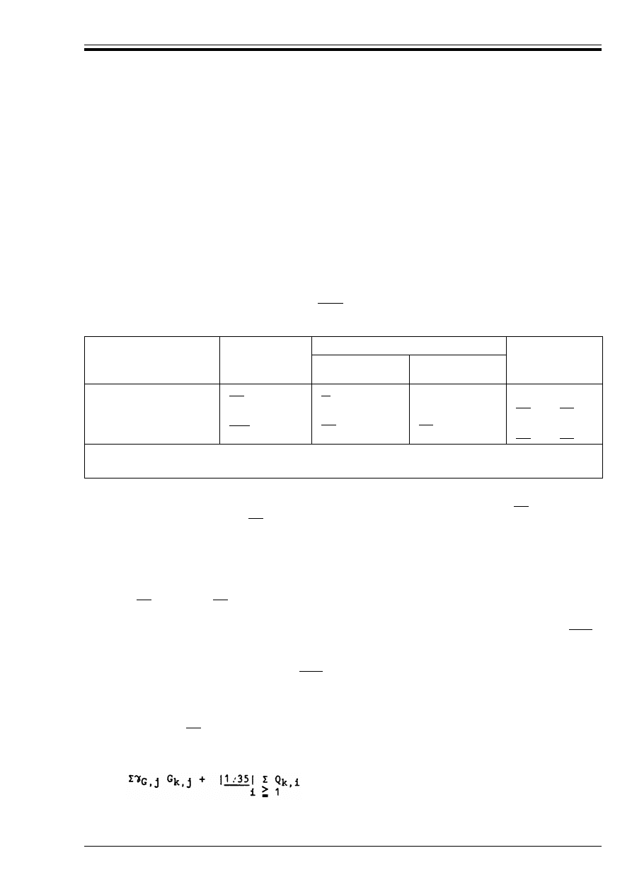
ENV 1992-1-1:1992
© BSI 12-1999
27
P(2) Except for the case in P(3) below, either the lower or the upper design value (whichever gives the more
unfavourable effect) shall be applied throughout the structure.
P(3) Where the results of a verification may be very sensitive to variations of the magnitude of a permanent
action from place to place in the structure, the unfavourable and the favourable parts of this action shall
be considered as individual actions. This applies in particular to the verification of static equilibrium. In
the afore-mentioned cases specific *
G
values need to be considered [see 2.3.3.1(3) for building structures].
(4) For continuous beams without cantilevers the same design value of the self-weight [evaluated as
in 2.2.2.2(3)] may be applied to all spans.
2.3.3 Partial safety factors for ultimate limit states
2.3.3.1
Partial safety factors for actions on building structures
(1) Partial safety factors for the persistent and transient design situations are given in Table 2.2.
(2) For accidental design situations to which expression [2.7(b)] applies, the partial safety factors for
variable actions and prestressing are equal to |unity|.
Table 2.2 — Partial safety factors for actions in building structures for persistent
and transient design situations
(3) Where, according to 2.3.2.3 P(3), favourable and unfavourable parts of a permanent action need to be
considered as individual actions, the favourable part should be associated with *
G,inf
=|0.9| and the
unfavourable part with *
G,sup
= |1.1|
P(4) Prestressing. For the evaluation of local effects (anchorage zones, bursting pressure) an effect
equivalent to the ultimate characteristic strength shall be applied to the tendons (see 2.5.4).
(5) For the verification of the design of prestressed elements, the *
p
values in Table 2.2 should generally
be used. However, for the evaluation of the combined effects of prestressing and of self-weight, reduced
values of partial safety factors, which do not include allowances for analytical uncertainty, may be used
(e.g. *
p
= |1.0| and *
G
= |1.2|), where prestressing is favourable).
(6) Imposed deformations. Where non-linear methods of analysis are used the factors for variable actions
given above apply. For a linear calculation, the factor for unfavourable effects shall be reduced by |20 %|
(i.e. *
Q
= 1.2).
(7) Vectorial effects. Where components of a vectorial force act independently, the factors applied to any
favourable component shall be reduced by |20 %|.
(8) By adopting the * values given in Table 2.2, the expression [2.7(a)] may be replaced by the following:
— for design situations with only one variable action Q
k1
— for design situations with two or more variable actions Q
k1
whichever gives the most unfavourable effects.
Permanent
actions (*
G
)
Variable actions (*
O
)
Prestressing (*
p
)
One with its
characteristic value
Others with their
combination value
Favourable effect
|1.0
a
|
|–
b
|
|
b
|
c
|0.9| or |1.0|
Unfavourable effect
|1.35
a
|
|1.5|
|1.5|
c
|1.2| or |1.0|
a
See also paragraph (3) below
b
See Eurocode 1; in normal cases for building structures *
Q,inf
= 0.
c
See relevant clauses
C*
G,j
G
k,j
+ |1.5| Q
k,1
[2.8(a)]
[2.8(b)]
Licensed copy:Heriot Watt University, 20/04/2004, Uncontrolled Copy, © BSI
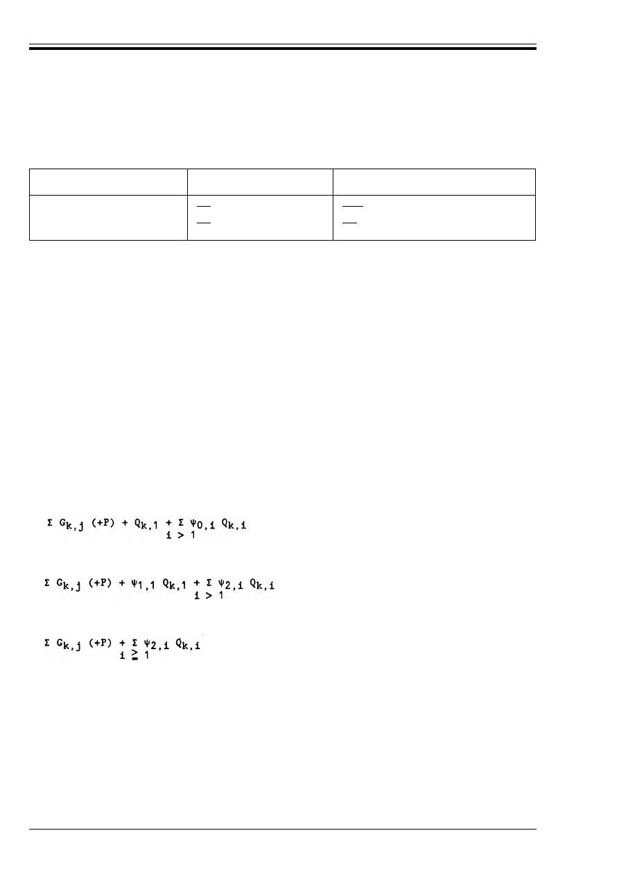
ENV 1992-1-1:1992
28
© BSI 12-1999
2.3.3.2
Partial safety factors for materials
(1) Partial safety factors for material properties are given in Table 2.3.
Table 2.3 — Partial safety factors for material properties
(2) These values are assumed to take account of differences between the strength of test specimens of the
structural materials and their strength in situ.
(3) The values given above are valid when the quality control procedures given in chapter 7 are followed.
They apply to characteristic values defined in chapter 3 and for design data as described in chapter 4.2.
(4) Higher or lower values of *
c
may be used if these are justified by adequate control procedures.
(5) These values do not apply for fatigue verification.
(6) Where structural properties are determined by testing, see the relevant Part of this Code.
2.3.4 Serviceability limit states
P(1) It shall be verified that
E
d
r C
d
or E
d
r R
d
where
The required combination is identified in the particular clause for serviceability verification (see 4.4).
P(2) Three combinations of actions for serviceability limit states are defined by the following expressions:
Rare combination
Frequent combination
Quasi-permanent combination
where the notation is defined in 2.3.2.2(2).
Imposed deformations should be considered when relevant.
(3) Upper limits of compressive stresses in the concrete in the presence of rare and quasi permanent
combinations may be fixed to avoid damage to the concrete and excessive creep deformations
(see chapter 4.4.1.).
(4) An upper limit of the tensile stress in the steel may be fixed to reduce the risk of inelastic deformation
and permanently open cracks (see chapter 4.4.1).
P(5) Where simplified compliance rules are given in the relevant clauses dealing with serviceability limit
states, detailed calculations using combinations of actions are not required.
Combination
Concrete
*
c
Steel reinforcement or prestressing tendons
*
s
Fundamental
|1,5|
|1,15|
Accidental (except
earthquakes)
|1,3|
|1,0|
C
d
is a nominal value or a function of certain design properties of materials related to the design
effects of actions considered, and
E
d
is the design effect of actions, determined on the basis of one of the combinations defined below.
[2.9(a)]
[2.9(b)]
[2.9(c)]
Licensed copy:Heriot Watt University, 20/04/2004, Uncontrolled Copy, © BSI
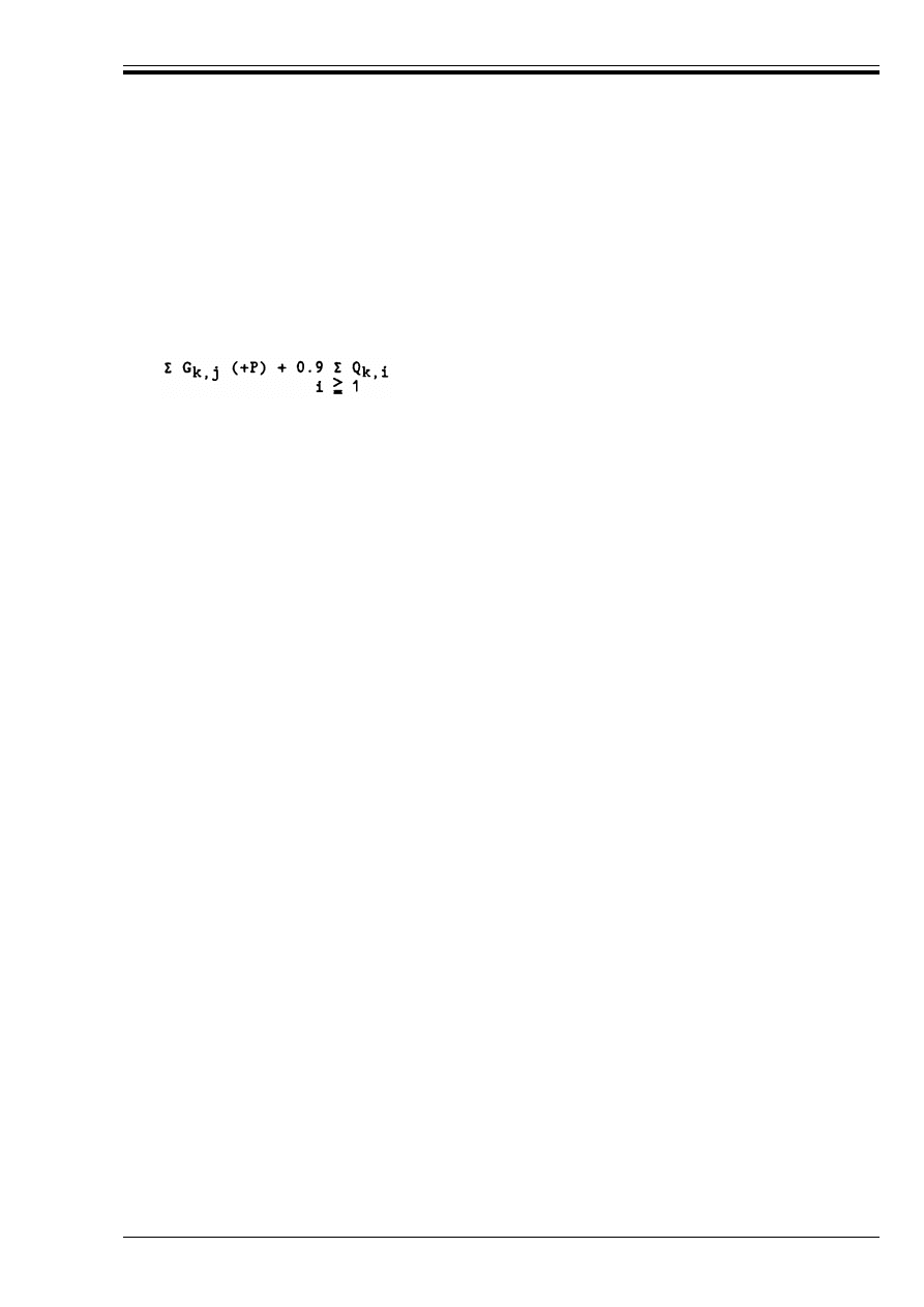
ENV 1992-1-1:1992
© BSI 12-1999
29
P(6) Where the design considers the compliance of serviceability limit states by detailed calculations,
simplified expressions may be used for building structures.
(7) For building structures the rare combination may be simplified to the following expressions, which
may also be used as a substitute for the frequent combination.
— design situations with only one variable action, Q
k.1
— design situations with two or more variable actions, Q
k.i
whichever gives the larger value.
P(8) Values of *
M
shall be taken as 1.0, except where stated otherwise in particular clauses.
2.4 Durability
P(1) To ensure an adequately durable structure, the following inter-related factors shall be considered:
— the use of the structure;
— the required performance criteria;
— the expected environmental conditions;
— the composition, properties and performance of the materials;
— the shape of members and the structural detailing;
— the quality of workmanship, and level of control;
— the particular protective measures;
— the likely maintenance during the intended life.
P(2) The environmental conditions shall be estimated at the design stage to assess their significance in
relation to durability and to enable adequate provisions to be made for protection of the materials.
2.5 Analysis
2.5.1 General provisions
2.5.1.0
Notation (see also 1.6 and 1.7)
2.5.1.1
General
P(1) The purpose of analysis is the establishment of the distribution of either internal forces and moments,
or stresses strains and displacements, over the whole or part of a structure. Additional local analysis shall
be carried out where necessary.
C G
k,j
(+ P) + Q
k,1
[2.9(d)]
[2.9(e)]
H
fd
Additional horizontal force to be considered in the design of horizontal structural elements, when
taking account of imperfections
%H
j
Increase in the horizontal force acting on the floor of a frame structure, due to imperfections
N
ba
}
N
bc
}
}
Design axial forces on columns or walls adjacent to a horizontal load transferring element, when
considering imperfections
1
Total height of a structure in metres
n
Number of vertical continuous members acting together
!
n
Reduction coefficient in calculating v (Equation 2.11)
5
Angle of inclination of a structure, assumed in assessing the effects of imperfections
Licensed copy:Heriot Watt University, 20/04/2004, Uncontrolled Copy, © BSI

ENV 1992-1-1:1992
30
© BSI 12-1999
(2) In most normal cases analysis will be used to establish the distribution of internal forces and moments;
however, for certain complex elements, the methods of analysis used (e.g. finite element analysis) give
stresses, strains and displacements rather than internal forces and moments. Special methods are
required to use these results to obtain appropriate reinforcement areas.
P(3) Analyses are carried out using idealisations of both the geometry and the behaviour of the structure.
The idealisations selected shall be appropriate to the problem being considered.
(4) The geometry is commonly idealised by considering the structure to be made up of linear elements, two
dimensional elements and, occasionally, shells. Geometrical idealisations are considered in 2.5.2.
(5) Common behavioural idealisations used for analysis are:
— elastic behaviour (see 2.5.3.2–2.5.3.3)
— elastic behaviour with limited redistribution (see 2.5.3.4.2)
— plastic behaviour (see 2.5.3.5.5), including strut and tie models (see 2.5.3.7)
— non-linear behaviour (see Appendix 2)
(6) Additional local analyses may be necessary where the assumption of linear strain distribution does not
apply, e.g.
— supports
— under concentrated loads
— beam and beam-column intersections
— anchorage zones
— changes in section.
2.5.1.2
Load cases and combinations
P(1) For the relevant combinations of actions, sufficient load cases shall be considered to enable the critical
design conditions to be established at all sections within the structure or part of the structure considered.
(2) Depending on the type of structure, its function or the method of construction, design may be carried
out primarily for either the ultimate limit state or the serviceability limit. In many cases, provided that
checks for one of these limit states have been carried out, checks for the other may be dispensed with as
compliance can be seen by experience.
(3) Simplified combinations of actions and load cases may be used, if based on a reasonable interpretation
of the structural response.
(4) For continuous beams and slabs in buildings without cantilevers subjected to dominantly uniformly
distributed loads, it will generally be sufficient to consider only the following load cases (see 2.3.2.2).
a) alternate spans carrying the design variable and permanent load (*
Q
Q
k
+ *
G
G
k
), other spans
carrying only the design permanent load, *
G
G
k
,
b) any two adjacent spans carrying the design variable and permanent loads (*
Q
Q
k
+ *
G
G
k
). All other
spans carrying only the design permanent load, *
G
G
k
.
(5) For linear elements and slabs in buildings, the effects of shear and longitudinal forces on the
deformations may be ignored where these are likely to be less than 10 % of those due to bending.
2.5.1.3
Imperfections
P(1) In the ultimate limit state, consideration shall be given to the effects of possible imperfections in the
geometry of the unloaded structure. Where significant, any possible unfavourable effect of such
imperfections shall be taken into account.
P(2) Individual sections shall be designed for the internal forces and moments arising from global analysis,
combining effects of actions and imperfections of the structure as a whole.
(3) In the absence of other provisions, the influence of structural imperfections may be assessed by
representing them as an effective geometrical imperfection using a procedure such as that given in (4)
to (8) below.
Licensed copy:Heriot Watt University, 20/04/2004, Uncontrolled Copy, © BSI
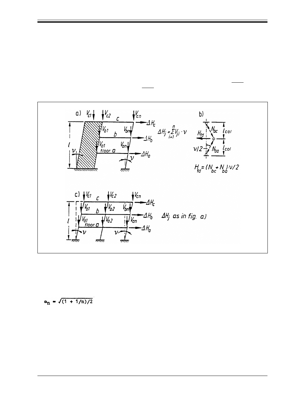
ENV 1992-1-1:1992
© BSI 12-1999
31
(4) Where a structure is being analysed as a whole, the possible effects of imperfections may be assessed
by assuming that the structure is inclined at an angle 5 to the vertical where:
where 1 is the total height of the structure in metres. 5 should not be taken as less than |1/400| for cases
where second order effects are insignificant or |1/200| where they have to be taken into account
(e.g. 4.3.5.4). [see Figure 2.1 a), Figure 2.1 b) and Figure 2.1 c)].
a) imperfections for the calculation of the horizontal forces on the bracing element
b) imperfections for the calculation of the horizontal forces in the floors transferring stabilising forces
from the braced sub-assembly to the bracing elements.
c) equivalent horizontal forces %H acting on an unbraced frame
(5) For cases where n vertical elements act together, 5, given by (4) above may be reduced by the factor !
n
given by Equation (2.11)
In Figure 2.1 a), n is n = 2; in Figure 2.1 c), n is n = 3.
(6) If more convenient, the deviations from the vertical given by (4) above may be replaced by equivalent
horizontal forces which should be taken into account in the overall analysis of the structure, bracing
elements, supports and ties (see Figure 2.1 a), Figure 2.1 b) and Figure 2.1 c).
(7) Structural elements which are assumed to transfer stabilising forces from the elements of a structure
to be braced to the bracing elements should be designed to carry an additional horizontal force H
fd
[see Figure 2.1 b)] such that:
5 = 1/(100ß1) (radians)
(2.10)
Figure 2.1 — Application of the effective geometrical imperfections
(2.11)
H
fd
= (N
bc
+ N
ba
) 5/2
(2.12)
Licensed copy:Heriot Watt University, 20/04/2004, Uncontrolled Copy, © BSI

ENV 1992-1-1:1992
32
© BSI 12-1999
where:
(8) Where the effects of imperfections are smaller than the effects of design horizontal actions, their
influence may be ignored. Imperfections need not be considered in accidental combinations of actions.
2.5.1.4
Second order effects
P(1) Second order effects shall be taken into account where they may significantly affect the overall
stability of a structure or the attainment of the ultimate limit state at critical sections.
(2) For normal buildings, second order effects may be neglected where they increase the moments,
calculated ignoring displacements, by not more than 10 %.
2.5.1.5
Time dependent effects
P(1) Time dependent effects shall be taken into account where significant.
(2) Creep and shrinkage normally need only be considered for the serviceability limit state except where
their influence in the ultimate limit state are likely to be significant.
2.5.1.6
Design by testing
P(1) The design of structures or structural elements may be based on testing.
(2) In this case, a specification for the test programme and interpretation of the results should be
approved nationally.
2.5.2 Idealisation of the structure
2.5.2.0
Notation (See also 1.6 and 1.7)
2.5.2.1
Structural models for overall analysis
P(1) The elements of a structure are normally classified, by consideration of their nature and function, as
beams, columns, slabs, walls, plates, arches, shells etc. Rules are provided for the analysis of the commoner
of these elements and of structures consisting of combinations of these elements.
(2) To be considered as a beam or column, the span or length of the member should not be less than twice
the overall section depth. A beam whose span is less than twice its depth is considered as a deep beam.
(3) To be considered as a slab, the minimum span should not be less than four times the overall slab
thickness.
(4) A slab subjected to dominantly uniformly distributed loads may be considered to be one-way spanning
if either:
a) it possesss two free (unsupported) and sensibly parallel edges or
b) if it is the central part of a sensibly rectangular slab supported on four edges with a ratio of the longer
to shorter span greater than 2.
(5) Ribbed or waffle slabs may be treated as solid slabs for the purposes of analysis, provided that the
flange or structural topping and transverse ribs have sufficient torsional stiffness. This may be assumed
provided that:
— the rib spacing does not exceed 1 500 mm
N
bc
and N
ba
denote the design axial forces on the adjacent columns or walls, acting on the load
transferring element being considered
H
fd
should not be taken into account in the design of the bracing elements.
a
1
,a
2
,a
i
Coefficients used in calculating values for effective spans (Equation 2.15 and Figure 2.4)
b
eff
Effective flange width of a T or L beam
h
f
Overall depth of a flange in T or L beams
l
eff
Effective span of beams and slabs
l
n
Clear distance between the faces of the supports
l
o
Length of span(s) between points of zero moment
t
Thickness of a supporting element
Licensed copy:Heriot Watt University, 20/04/2004, Uncontrolled Copy, © BSI
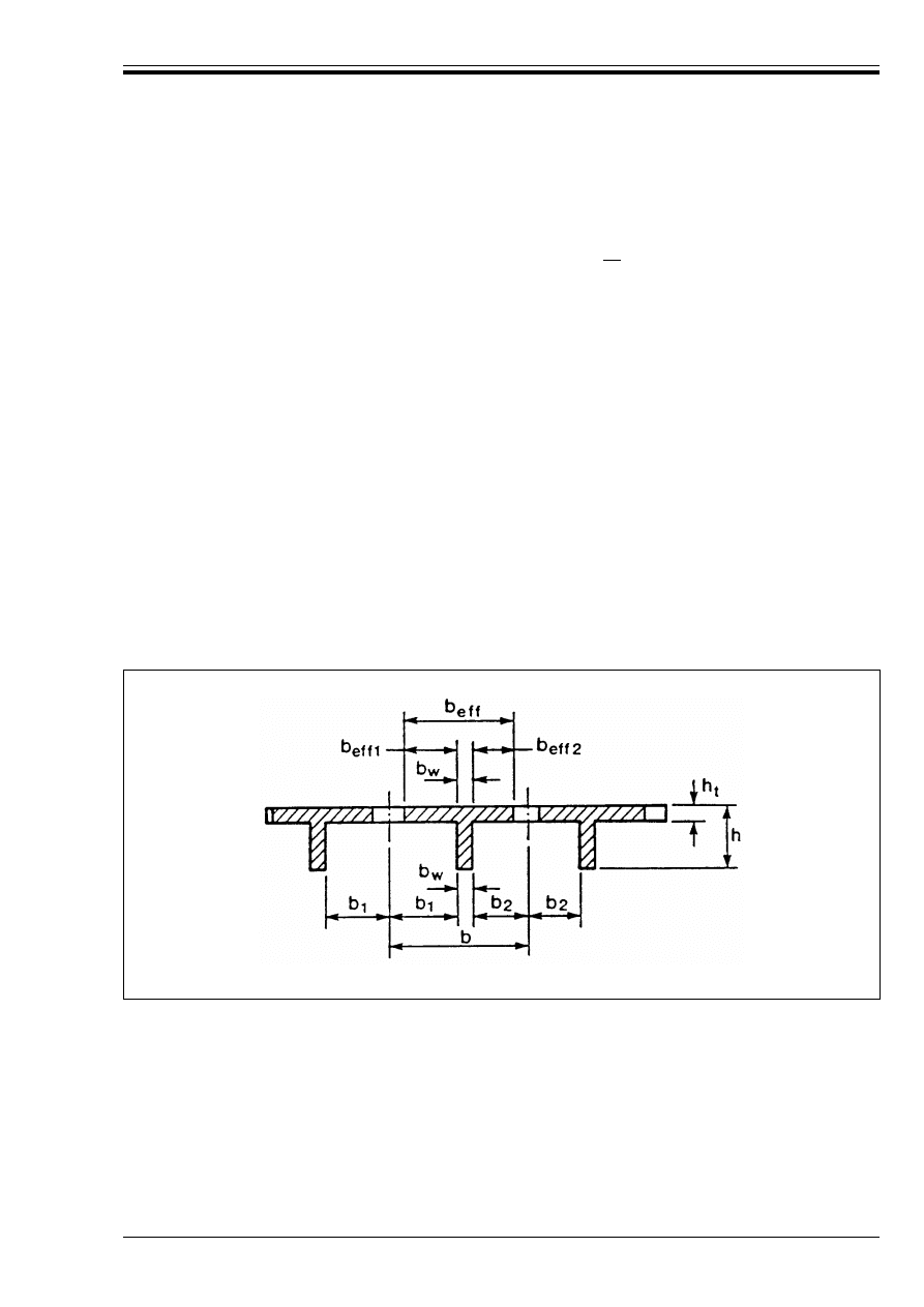
ENV 1992-1-1:1992
© BSI 12-1999
33
— the depth of the rib below the flange does not exceed four times its width
— the depth of the flange is at least 1/10 of the clear distance between ribs or 50 mm, whichever is the
greater.
— transverse ribs are provided at a clear spacing not exceeding |10| times the overall depth of the slab.
The minimum flange thickness of 50 mm may be reduced to 40 mm where permanent blocks are
incorporated between the ribs.
(6) A wall should have a horizontal length of at least four times its thickness. Otherwise it should be
treated as a column.
2.5.2.2
Geometrical data
2.5.2.2.1 Effective width of flanges (all limit states)
P(1) In T beams the effective flange width depends on the web and flange dimensions, the type of loading,
the span, the support conditions and the transverse reinforcement.
(2) For analysis, when a great accuracy is not required (e.g. continuous beams in buildings), a constant
width may be assumed over the whole span.
(3) The effective width for a symmetrical T beam may be taken as:
(4) The distance l
o
between points of zero moment may be obtained from Figure 2.3 for typical cases.
(2.13)
and, for an edge beam (i.e. with flange on one side only)
(2.14)
(for the notations see Figure 2.2 and Figure 2.3 below).
Figure 2.2 — Definition of dimensions
b
eff
b
w
1
5
--- 1
o
b
<
+
=
b
effi
b
w
1
10
------ l
o
b
i
b
w
i
1 or 2
=
(
)
+
≤
+
=
Licensed copy:Heriot Watt University, 20/04/2004, Uncontrolled Copy, © BSI
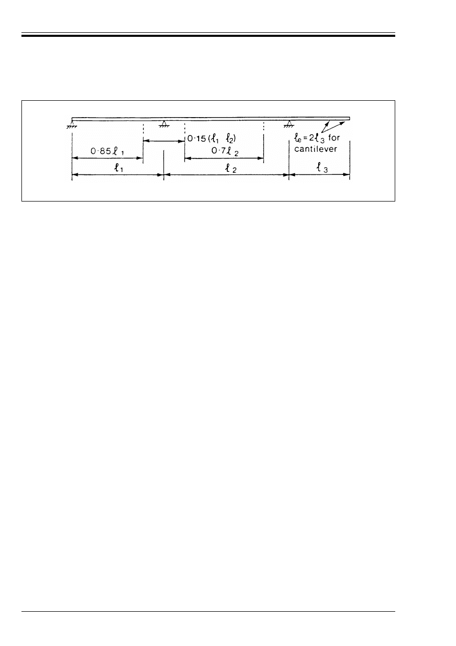
ENV 1992-1-1:1992
34
© BSI 12-1999
The following conditions should be satisfied:
i) The length of the cantilever should be less than half the adjacent span.
ii) The ratio of adjacent spans should lie between 1 and 1.5.
(5) For the dispersion of prestressing forces in T beams see 4.2.3.5.3.
2.5.2.2.2 Effective span of beams and slabs
(1) The effective span (l
eff
) of a member may be calculated as follows:
where:
Figure 2.3 — Approximate effective spans for calculation of effective breadth ratios
l
eff
= l
n
+ a
1
+ a
2
(2.15)
l
n
is the clear distance between the faces of the supports
values for a
1
and a
2
, at each end of the span, may be determined from the appropriate a
i
values
in Figure 2.4.
Licensed copy:Heriot Watt University, 20/04/2004, Uncontrolled Copy, © BSI
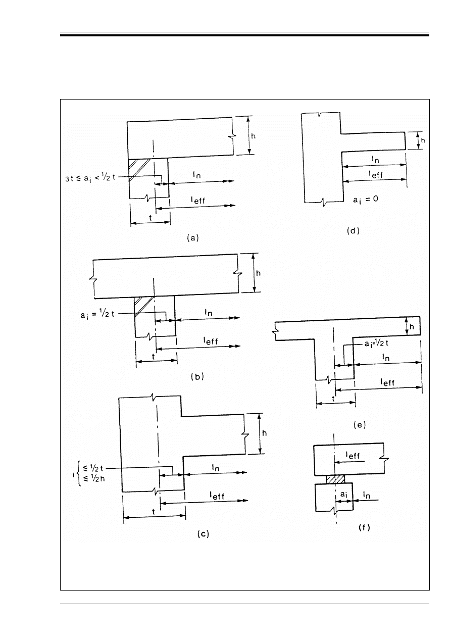
ENV 1992-1-1:1992
© BSI 12-1999
35
(
a) Non-continuous members
(b) Continuous members
(c) Supports considered fully restrained
(d) Isolated cantilever
(e) Continuous cantilever
(f) Bearing provided
Figure 2.4 — Determination of effective span (l
eff
) according to Equation (2.15)
for different support conditions
Licensed copy:Heriot Watt University, 20/04/2004, Uncontrolled Copy, © BSI

ENV 1992-1-1:1992
36
© BSI 12-1999
2.5.3 Calculation methods
2.5.3.0
Notation (See also 1.6 and 1.7)
2.5.3.1
Basic considerations
P(1) All methods of analysis shall satisfy equilibrium.
P(2) If compatibility conditions are not checked directly for the limit states considered, then measures shall
be taken to ensure that, at the ultimate limit states, the structure has sufficient deformation capacity and
that unsatisfactory performance under service conditions is avoided.
P(3) Normally, equilibrium will be checked on the basis of the undeformed structure (first order theory).
However, in cases where deformations lead to a significant increase in the internal forces and moments,
equilibrium shall be checked considering the deformed structure (second order theory) (see 2.5.1, 4.3.5).
P(4) Global analysis for imposed deformations, such as temperature and shrinkage effects, may be omitted
where structures are divided, by joints, into sections chosen to accommodate the deformations.
(5) In normal cases, such sections should not exceed |30 m|
2.5.3.2
Types of structural analysis
2.5.3.2.1 Serviceability analysis
P(1) Analyses carried out in connection with serviceability limit states will normally be based on linear
elastic theory.
(2) In this case it will normally be satisfactory to assume a stiffness for members based on the stiffness of
the uncracked cross-section and an elastic modulus as defined in 3.1.2.5.2. Allowance for
time-dependent effects should be made if these are likely to be significant (see 3.1 and 3.3).
P(3) Where cracking of the concrete has a significant unfavourable effect on the performance of the
structure or member considered, it shall be taken into account in the analysis. Where the effect is
favourable, it may be taken into account provided compatibility conditions are satisfied.
2.5.3.2.2 Ultimate limit states
P(1) Depending on the specific nature of the structure, the limit state being considered and on the specific
conditions of design or execution, analysis for the ultimate limit states may be linear elastic with or without
redistribution, non-linear or plastic.
P(2) The method used should be formulated so that, within its defined field of validity, the level of
reliability generally required by this code is achieved, taking account of the particular uncertainties
associated with the method. See, for example, 2.5.3.4.2.
P(3) In this section, the term “non-linear analysis” relates to analyses which take account of the
non-linear deformation properties of reinforced or prestressed concrete sections. Analyses which take
account of non-linear behaviour resulting from the deformation of elements are termed “second order
analyses” (thus a “non linear second order analysis” takes account of both effects).
F
v
Vertical force acting on a corbel
F
Sd,sup
Design support reaction
H
c
Horizontal force acting at the bearing on a corbel
%M
Sd
Reduction in the design support moment for continuous beams or slabs, due to the support
reaction F
sd.sup,
when the support provides no restraint to rotation
a
c
Distance between the point of application of the applied vertical load and the face of the
supporting member (corbel design)
b
sup
Breadth of a support
h
c
Overall depth of a corbel at the face of the supporting member
$
Ratio of redistributed moment to the moment before redistribution
5
Coefficient relating the average design compressive stress in struts to the design value of
concrete compressive strength (f
cd
)
Licensed copy:Heriot Watt University, 20/04/2004, Uncontrolled Copy, © BSI

ENV 1992-1-1:1992
© BSI 12-1999
37
(4) The application of linear elastic theory will normally require no specific measures to ensure adequate
ductility, provided that very high percentages of reinforcement are avoided at critical sections. However,
where the moments obtained from linear elastic analysis are redistributed, it is necessary to ensure that
critical sections have a rotation capacity sufficient to accommodate the amount of redistribution carried
out.
(5) The plastic approach to analysis may be used only for very ductile structural elements where high
ductility steel is used (see 3.2.4.2).
(6) Wherever possible, reinforcement splices should be located away from critical sections. If this is not
possible, the deformation or rotation capacity of the splice region should be assessed on the basis of the
total amount of reinforcement present.
2.5.3.3
Simplifications
P(1) Simplified methods or design aids based on appropriate simplifications may be used for analysis
provided they have been formulated to give the level of reliability implicit in the methods given in this
code over their stated field of validity. Redistribution is limited to that permitted by the assumptions
implicit in the chosen simplified method.
(2) A value of zero may be taken for Poisson’s ratio in place of the value given in 3.1.2.5.3.
(3) Continuous slabs and beams may generally be analysed on the assumption that the supports provide
no rotational restraint.
(4) Regardless of the method of analysis used, where a beam or slab is continuous over a support which
may be considered to provide no restraint to rotation, the design support moment, calculated on the basis
of a span equal to the centre-to-centre distance between supports, may be reduced by an amount %M
Sd
where:
(5) Where a beam or slab is cast monolithically into its supports, the critical design moment at the support
may be taken as that at the face of the support but not less than the value given
by 2.5.3.4.2(7).
(6) The loads applied to supporting members by the reactions from one-way spanning slabs, ribbed slabs
and beams (including T beams) may be calculated on the assumption that the members supported are
simply supported. Continuity should, however, be taken into account at the first internal support and at
other internal supports if the spans on either side of the support differ by more than 30 %.
2.5.3.4
Structural analysis of beams and frames
2.5.3.4.1 Acceptable methods of analysis
P(1) Any of the methods given in 2.5.3.2.2(1) may be used.
2.5.3.4.2 Linear analysis with or without redistribution
P(1) The possible influence on all aspects of the design of any redistribution of the moments shall be taken
into account. These aspects include bending, shear, anchorage and curtailment of the reinforcement and
cracking.
P(2) The moments calculated using a linear elastic analysis may be redistributed provided that the
resulting distribution of moments remains in equilibrium with the applied loads.
(3) In continuous beams where the ratio of adjacent spans is less than 2, in beams in non-sway frames and
in elements subject predominantly to flexure, an explicit check on the rotation capacity of critical zones
may be omitted provided that the conditions a) and b) given below are satisfied.
a) for concrete grades not greater than C 35/45
for concrete grades greater than C 35/45
$
T 0.56 + 1.25 x/d
%M
Sd
= F
Sd.sup
b
sup
/8
(2.16)
F
Sd.sup
is the design support reaction
b
sup
is the breadth of the support
$
T 0.44 + 1.25 x/d
(2.17)
Licensed copy:Heriot Watt University, 20/04/2004, Uncontrolled Copy, © BSI

ENV 1992-1-1:1992
38
© BSI 12-1999
b) For high ductility steel, $ T 0.7
For normal ductility steel, $ T 0.85
where:
For definitions of steel classes, see 3.2.4.2.
(4) In general, no redistribution is permitted in sway frames.
(5) In elements as defined in (3), where no redistribution has been carried out, the ratio of x/d should not
exceed
x/d = 0.45 for concrete Grades C12/15 to C35/45
x/d = 0.35 for concrete Grade C40/50 and greater
at the critical section unless special detailing provisions (e.g. confinement) are made.
(6) Redistribution should not be carried out in circumstances where the rotation capacity cannot be defined
with confidence (e.g. in the corners of prestressed frames).
(7) To allow for approximations in the idealisation of the structure and for possible unconsidered
differences in the structural form during construction, the design moment at the faces of rigid supports in
continuous spans should not be less than 65 % of the support moment calculated assuming full fixity at the
faces of the rigid supports.
2.5.3.4.3 Non-linear analysis
See Appendix 2.
2.5.3.4.4 Plastic Analysis
See Appendix 2
2.5.3.5
Analysis of slabs
2.5.3.5.1 Scope
P(1) This section applies to slabs as defined in Section 2.5.2.1 subjected to bi-axial internal moments and
forces. It may be extended to non solid slabs (ribbed, hollow, waffle slabs) if their response is similar to that
of a solid slab, particularly with regard to the torsional stiffness.
(2) One-way spanning slabs subjected mainly to uniformly distributed loading may be considered as
beams and be analysed according to 2.5.3.4.
(3) For flat slabs, a minimum design moment should be provided over supports to ensure the validity of
the design for punching shear (see 4.3.4.5.3).
2.5.3.5.2 Determination of action effects
P(1) 2.5.3.1, paragraphs (1) and (2) apply.
2.5.3.5.3 Acceptable methods of analysis
P(1) The following methods of analysis may be used:
a) linear analysis with or without redistribution;
b) plastic analysis based either on the kinematic method (upper bound) or on the static method (lower
bound);
c) numerical methods taking account of the non-linear material properties;
(2) The application of linear methods of analysis is suitable for the serviceability limit states as well as for
the ultimate limit states. Plastic methods, with their high degree of simplification, should only be used in
the ultimate limit states.
(3) Current methods of plastic analysis are: the yield line theory (kinematic method) and the strip method
(lower bound or static method).
$
is the ratio of the redistributed moment to the moment before redistribution
x
is the neutral axis depth at the ultimate limit state after redistribution
d
is the effective depth.
Licensed copy:Heriot Watt University, 20/04/2004, Uncontrolled Copy, © BSI

ENV 1992-1-1:1992
© BSI 12-1999
39
2.5.3.5.4 Linear analysis with or without redistribution
P(1) For linear analysis with or without redistribution the same conditions as given for beams and frames
in 2.5.3.4.2(2) apply.
(2) The bending moment at continuous edges may be reduced as defined in 2.5.3.4.2(2) and (3).
(3) For checking shear, torsion and bearing reactions, a linear interpolation between the action effects of a
fully restrained edge and those of a simply supported edge may be used.
(4) See Appendix 2 for reinforcement proportioning in situations where the directions of the principal
moments do not coincide with those of the reinforcement.
2.5.3.5.5 Plastic methods of analysis
P(1) Plastic analysis without any direct check on rotation capacity may be used for the ultimate limit state
if appropriate ductility conditions are met.
(2) When using plastic analysis, the area of tensile reinforcement should not exceed, at any point or in any
direction a value corresponding to x/d = 0.25
(3) A check on the rotational capacity is not necessary for high ductility reinforcing steel (see 3.2.4.2).
Normal ductility steel should not be used unless its application can be justified.
(4) For the kinematic method, a variety of possible mechanisms should be examined assuming the design
values of the material properties appropriate for the ultimate limit state.
(5) The ratio of the moments over continuous edges to the moments in the span should be between:
|0.5 and 2.0|
(6) When static methods of plastic analysis are used, it may be convenient to determine the distribution of
moments on the basis of a linear analysis and to design the necessary reinforcement on a plastic
interpretation of this distribution by satisfying the equilibrium conditions. (See Appendix 2 for
reinforcement proportioning).
2.5.3.5.6 Numerical methods of non-linear analysis
See Appendix 2.
2.5.3.5.7 Analysis of prestressed slabs
(1) The rules given in (2)–(4) below complement those given in Section 2.5.4.
(2) Regardless of the type of tendons used (e.g. bonded or unbonded), the contact forces due to the curvature
and friction of the tendons and the forces acting on the anchorage devices may be treated as external loads
in the serviceability limit states.
(3) For the ductility classification of prestressed tendons see 3.3.4.3(3)
(4) Plastic analysis should not be applied to members where pretensioned tendons are used, unless
justified.
2.5.3.6
Structural analysis of walls and plates loaded in their own plane
2.5.3.6.1 Permitted methods of analysis
P(1) This section applies to elements for which the assumption of a linear strain distribution is not valid.
P(2) The following methods may be used for the determination of the internal forces and moments:
a) Methods based on linear analysis (see 2.5.3.6.2)
b) Methods based on plastic analysis (see 2.5.3.6.3)
c) Methods based on non-linear material behaviour (see Appendix 2).
P(3) Independently from the procedure adopted in the ultimate limit state, possible model uncertainty
related to the overall response of the structure shall be taken into account.
P(4) Corbels and deep beams are special cases and are treated in 2.5.3.7.2 and 2.5.3.7.3 respectively.
2.5.3.6.2 Linear analysis
P(1) Linear analysis may be used for both the serviceability limit states and the ultimate limit states.
However analysis for the ultimate limit states requires detailing of the reinforcement which is able to
withstand the totality of the design tensile stresses in the concrete and which satisfies the equilibrium
conditions in the ultimate limit states.
Licensed copy:Heriot Watt University, 20/04/2004, Uncontrolled Copy, © BSI

ENV 1992-1-1:1992
40
© BSI 12-1999
P(2) Imposed deformation (e.g. thermal effects, settlements of the supports) and second order effects shall
be considered when significant.
P(3) When using numerical methods based on the theory of elasticity, cracking effects in regions of high
stress concentration shall be taken into account.
(4) The effects of high stress concentrations may be allowed for by a reduction in the rigidity of the
relevant zones.
(5) See also Appendix 2, clause A.2.8.
2.5.3.6.3 Plastic analysis
P(1) Methods based on lower bound plastic solutions may be used provided appropriate measures are taken
to ensure that ductility conditions are satisfied.
(2) Elements may be idealised as statically determinate trusses consisting of straight notional struts
(carrying the compressive forces in the concrete) and ties (the reinforcement). The forces in the members
of the truss are established from considerations of equilibrium. Sufficient reinforcement is then provided
to carry the tension in the ties and a check is performed to ensure that the compressive stresses in the
struts are not excessive. Detailing requirements should then be checked, with particular regard to
anchorage of all reinforcement, and to local bearing stresses due to concentrated forces.
(3) In order to ensure approximate compatibility, the location and orientation of the struts and ties should
reflect the distribution of internal forces resulting from an elastic analysis of the member.
(4) In checking concrete stresses in the struts, consideration should be given to a possible reduction in
strength due to transverse tensile stresses, or cracking or the influence of shear. The average design
compressive stress in the struts may be taken as 5.f
cd
. In the absence of other data, 5 may be taken
as |0.6|, including an allowance for sustained loading. Higher values for 5 (even 5 > 1) may be justified
based on a triaxial state of compressive stress, provided it can be shown that the complementary
transverse compression can be realised in practice (See 5.4.8.1).
(5) The design stress in the ties is limited to f
yd
.
(6) Detailing should comply with 5.4.
2.5.3.6.4 Non-linear analysis
(1) See Appendix 2.
2.5.3.7
Corbels, deep beams, and anchorage zones for post-tensioning forces
2.5.3.7.1 General
(1) These types of elements may be analysed, designed and detailed in accordance with 2.5.3.6.3.
2.5.3.7.2 Corbels
(1) Corbels with 0.4 h
c
r a
c
r h
c
(See Figure 2.5) may be designed using a simple strut and tie model.
(2) For deeper corbels (a
c
< 0.4 h
c
), other adequate strut and tie models may be considered.
(3) Corbels for which a
c
> h
c
may be designed as cantilever beams
(4) Unless special provision is made to limit horizontal forces on the support, or other justification is given,
the corbel should be designed for the vertical force F
v
, and a horizontal force H
c
T |0.2 F
v
| acting at the
bearing area.
(5) The overall depth (h
c
) of the corbel should be determined from considerations of shear (see 4.3.2).
(6) The local effects due to the assumed strut and tie system should be considered in the overall design of
the supporting member.
P(7) The detailing requirements of Chapter 5 generally, and 5.4.4 in particular, shall be met.
Licensed copy:Heriot Watt University, 20/04/2004, Uncontrolled Copy, © BSI
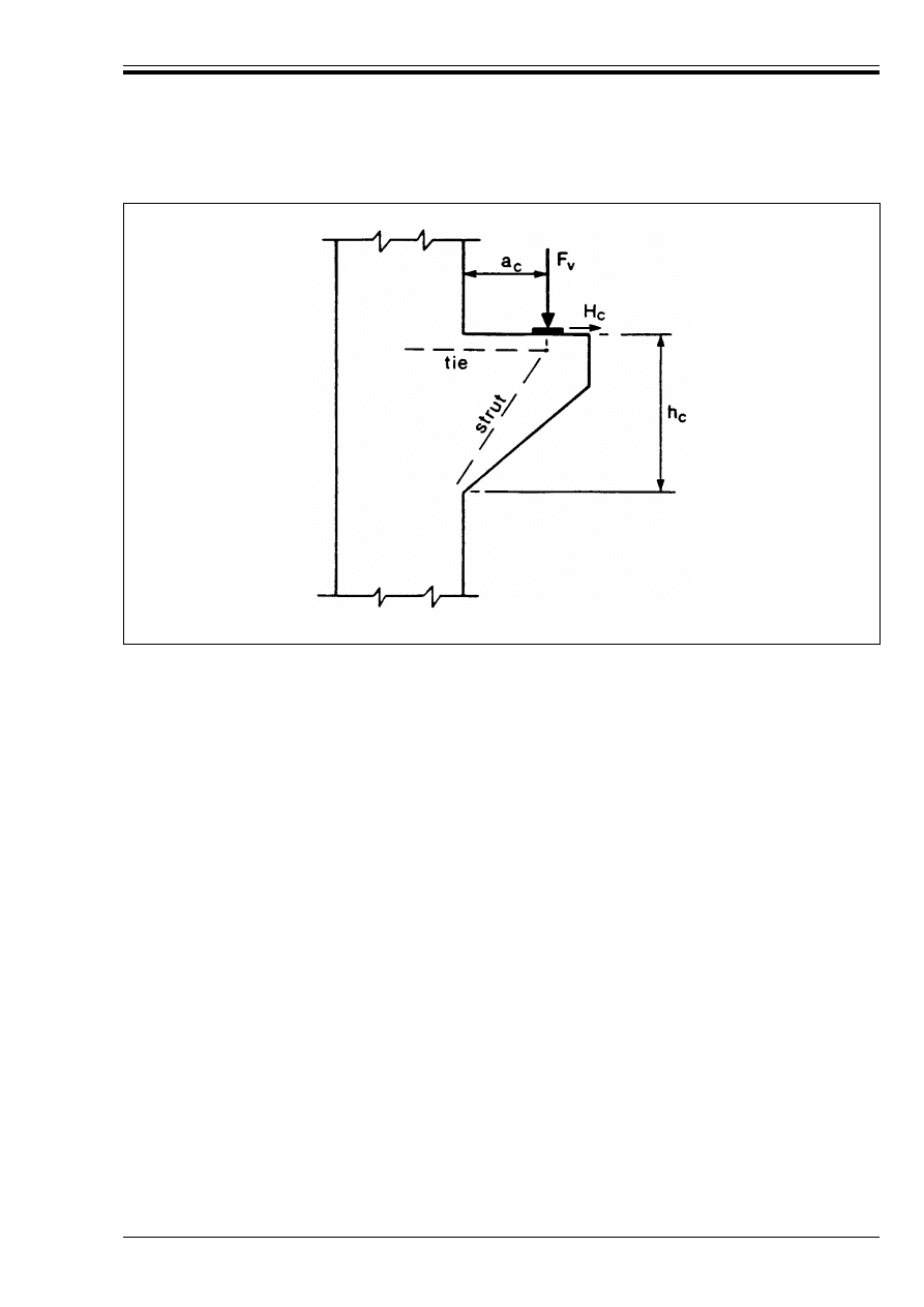
ENV 1992-1-1:1992
© BSI 12-1999
41
2.5.3.7.3 Deep beams
(1) Deep beams under a concentrated load may be designed using a simple strut and tie model.
(2) In some cases, e.g. lower depth/span ratios, distributed loads, more than one concentrated load, etc.,
models combining strut and tie action with truss action may be used.
(3) Continuous deep beams are sensitive to differential settlement. A range of support reactions,
corresponding to possible settlements, should therefore be considered.
P(4) The detailing requirements of Chapter 5 generally, and 5.4.5 in particular, shall be met.
2.5.3.7.4 Zones subjected to concentrated forces
P(1) Such zones shall be analysed and designed to take account of:
— the overall equilibrium of the zone;
— the transverse tensile effects due to the anchorages, individually and as a whole;
— compression struts, which develop in the anchorage zone of post-tensioned members, and local
bearing stresses under the anchorages.
(2) Such zones in post-tensioned members may be designed by using adequate strut and tie models based
on 2.5.3.6.3.
(3) Three-dimensional models should be considered, where the dimensions of the bearing area are small
compared with the cross-section of the anchorage zone.
P(4) The detailing requirements of Chapter 5 generally, and 5.4.6 in particular, shall be met.
2.5.4 Determination of the effects of prestressing
2.5.4.0
Notation (See also 1.6 and 1.7)
Figure 2.5 — Example of a corbel, with a strut and tie model
P
d
Design value of the prestressing force at the ultimate limit state (Assuming that P
m.t
is equal to
P
k
— see 2.2.2.4)
P
k,inf
Lower characteristic value of the prestressing force for serviceability calculations
P
k,sup
Upper characteristic value of the prestressing force for serviceability calculations
Licensed copy:Heriot Watt University, 20/04/2004, Uncontrolled Copy, © BSI

ENV 1992-1-1:1992
42
© BSI 12-1999
2.5.4.1
General
P(1) This section relates to structures where prestress is provided by fully bonded internal tendons.
P(2) The effects to be considered are:
— local effects around anchorages and where tendons change direction
— direct effects in determinate structures
— direct and secondary indirect effects due to redundant restraints in indeterminate structures.
(3) Members containing permanently unbonded tendons are covered in Part 1D.
(4) Members containing tendons which are temporarily unbonded during construction may be treated
using simplified assumptions. In general, they may be treated as members with bonded tendons, except
that at the ultimate limit state, the stress in tendons is assumed not to have increased due to loading.
2.5.4.2
Determination of prestressing force
P(1) The mean value of the prestressing force is given by a) or b) below, whichever is appropriate:
a) for pre-tensioned members:
%P
u
(x) may require consideration where deflected tendons are used.
b) for post-tensioned members:
where:
(2) For limits on the initial prestress and methods of calculating losses, see 4.2.3. For transmission
lengths and the dispersion of prestress, see 4.2.3.5.
P
o
Initial force at the active end of the tendon immediately after stressing
P
m,o
Mean value of the prestressing force immediately after stressing (post-tensioning) or transfer
(pre-tensioning) at any point distance x along the member (i.e. the force after immediate losses
have occurred)
P
m,t
Mean value of the prestressing force at time t, at any point distance x along the member
P
m,
Z
Mean value of the prestressing force, after all losses have occurred, at any point distance x
along the member
P
o,max
Maximum permissible value of P
o
%P
c
Loss of prestress due to elastic deformation of the member at transfer
%P
sl
Loss of prestress due to anchorage slip
%P
t
(t)
Loss of prestress due to creep, shrinkage and relaxation at time t (Note: in 4.2.3.5.5, the loss of
stress from which %P
t
(t) is calculated is represented by %Bp
p, c + s + r
)
%P
u
(X)
Loss of prestress due to friction
r
inf
}
r
sup
}
}
Respectively, coefficients used to determine lower and upper characteristic values of the
prestressing force at the serviceability limit state
P
m,t
= P
o
– %P
c
– %P
t
(t) – (%P
u
(x))
(2.18)
P
m,t
= P
o
– %P
c
– %P
u
(x) – %P
s1
– %P
t
(t)
(2.19)
P
m,t
is the mean value of the prestressing force at time t and at a particular point along the
member
P
o
is the initial force at the active end of the tendon immediately after stressing
%P
u
(x)
is the loss due to friction
%P
sl
is the loss due to anchorage slip
%P
c
is the loss due to elastic deformation of the member at transfer
%P
t
(t)
is the loss due to creep, shrinkage and relaxation at time t
Licensed copy:Heriot Watt University, 20/04/2004, Uncontrolled Copy, © BSI

ENV 1992-1-1:1992
© BSI 12-1999
43
P(3) For serviceability calculations, allowance shall be made for possible variations in prestress.
Two characteristic values of the prestressing force at the serviceability limit state are estimated from:
where P
k.sup
and P
k.inf
are respectively the upper and lower characteristic values. P
m,t
is the mean
prestressing force estimated using the mean values for the deformation properties and the losses calculated
in accordance with 4.2.3.
(4) The coefficients r
sup
and r
inf
may be taken as |1.1| and |0.9| respectively in absence of a more
rigorous determination and provided that the sum of the losses due to friction and time dependent effects
is r 30 % of the initial prestress.
(5) The values of P
m.t
which will generally be used in design are:
P
m,o
– the initial prestress at time t = 0
and
P
m, Z
– the prestress after occurrence of all losses.
P(6) At the ultimate limit state, the design value of prestress is given by:
P
d
= *
p
P
m.t
(7) Values for *
p
are given in Table 2.2.
P(8) For considering local effects at the ultimate limit state, the prestressing force shall be taken as equal
to the characteristic strength of the tendons.
(9) This applies when checking the influence of concentrated forces or bursting effects at anchorages or
where tendons change direction. (See 4.2.3).
2.5.4.3
Effects of prestressing under service conditions
P(1) The statically determinate and indeterminate internal forces and moments caused by prestressing
shall be calculated by elastic theory.
(2) For normal buildings where the calculation of crack width is not considered necessary, the mean
values of prestress may be used.
(3) In other cases, where the structural response is highly sensitive to the influence of prestress, the
effects of prestress may be determined according to a) or b) below, as appropriate.
a) for checking cracking or decompression (see 4.4.2), the opening of joints between precast elements and
fatigue effects, the relevant estimated characteristic values of the prestress are used.
b) for checking compressive stresses (see 4.4.1), the mean values of prestress are used.
2.5.4.4
Effects of prestressing at the ultimate limit states
2.5.4.4.1 Structural analysis — linear methods
P(1) Statically determinate and indeterminate effects of prestress shall be calculated using the appropriate
ultimate design value of the prestressing force.
(2) In linear structural analysis, *
p
may be taken as 1.0.
P(3) Where linear analysis with redistribution is used, the moments to which the redistribution is applied
shall be calculated including any statically indeterminate effects of prestress.
2.5.4.4.2 Structural analysis — non-linear or plastic methods
(1) See Appendix 2.
2.5.4.4.3 Design of sections
P(1) When assessing the behaviour of a section at the ultimate limit state, the prestressing force acting on
the section is taken as the design value, P
d
. The prestrain corresponding to this force shall be taken into
account in the assessment of section strength.
(2) The prestrain may be taken into account by shifting the origin of the design stress-strain diagram for
the prestressing tendons by an amount corresponding to the design prestress.
P
k.sup
= r
sup
P
m,t
(2.20)
P
k.inf
= r
inf
P
m,t
Licensed copy:Heriot Watt University, 20/04/2004, Uncontrolled Copy, © BSI

ENV 1992-1-1:1992
44
© BSI 12-1999
(3) *
p
may be taken as 1.0 provided the following conditions are both met:
a) not more than 25 % of the total area of prestressed steel is located within the compression zone at the
ultimate limit state.
and
b) the stress at ultimate in the prestressing steel closest to the tension face exceeds f
p
0.1k/*
m
.
If the conditions are not met, the lower value of *
p
given in Table 2.2 should be applied to all tendons.
(4) For the effects of inclined tendons, see 4.3.2.4.6(2).
(5) Any indirect prestressing moments due to redundant restraints should be taken at their characteristic
values.
2.5.5 Determination of the effects of time dependent deformation of concrete
2.5.5.0
Notation (See also 1.6 and 1.7)
2.5.5.1
General
P(1) The accuracy of the procedures for the calculation of the effects of creep and shrinkage of concrete shall
be consistent with the reliability of the data available for the description of these phenomena and the
importance of their effects on the limit state considered.
P(2) In general, the effects of creep and shrinkage shall be taken into account only for the serviceability
limit states. An important exception concerns second order effects (see Appendix 3).
P(3) Special investigations shall be considered when the concrete is subjected to extremes of temperature.
(4) The effects of steam curing may be taken into account by means of simplified assumptions.
(5) The following assumptions may be adopted to give an acceptable estimate of the behaviour of a
concrete section if the stresses are kept within the limits corresponding to the normal service conditions:
— creep and shrinkage are independent
— a linear relationship is assumed between creep and the stress causing the creep.
— non-uniform temperature or moisture effects are neglected.
— the principle of superposition is assumed to apply for actions occurring at different ages.
— the above assumptions also apply to concrete in tension.
P(6) For the evaluation of the time dependent losses of prestress, the effects of creep, shrinkage and
relaxation of the tendons shall be taken into account. (See 4.2.3.5).
(7) The creep function is given by the relationship:
where:
E
c,eff
Effective tangent modulus of elasticity of the concrete at a stress B
c
= 0
(
n
(t)
An imposed deformation, independent of stress (e.g. due to shrinkage or temperature effects)
(
tot
(t,t
o
)
Total strain in the concrete subject to initial loading at time t
o
with a stress B(t
o
) and subject
to subsequent stress variations %B(t
i
)
B(t) )
B(t
o
) )
Compressive stress in the concrete at time t and t
o
respectively
x
Ageing coefficient, dependent on strain development with time
J(t,t
o
) = 1/E
c
(t
o
) + Ì(t,t
o
)/E
c28
(2.21)
t
o
is the time at initial loading of the concrete
t
is the time considered
J(t,t
o
)
is the creep function at time t
E
c
(t
o
)
is the tangent modulus of elasticity at time t
o
E
c28
is the tangent modulus of elasticity at 28 days
Licensed copy:Heriot Watt University, 20/04/2004, Uncontrolled Copy, © BSI
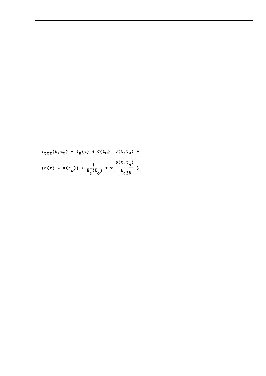
ENV 1992-1-1:1992
© BSI 12-1999
45
Values are given in section 3.1 for final creep coefficients Ì(Z,t
o
) for typical situations. It should be noted,
however, that the definitions of E
c
(t
o
) and E
c28
above, as well as in Appendix 1, differ from that
in 3.1.2.5.2 where the secant modulus E
cm
is defined. Hence, where the creep coefficients Ì( ,t
o
) of
Table 3.3 are used in connection with Equations 2.21–2.24, and where creep deformations are significant,
the values of Table 3.3 should be multiplied by 1.05.
(8) Values for the final shrinkage strains are given for typical conditions in 3.1.
(9) On the basis of the assumptions listed in (5) above the total strain for concrete subjected to initial
loading at time to with a stress B(t
o
) and subjected to subsequent stress variations %B(t
i
) at time t
i
may be
expressed as follows:
In this expression (
n
(t) denotes an imposed deformation independent of the stresses (e.g. shrinkage,
temperature effects).
(10) For the purpose of structural analysis, equation (2.22) may be written as follows:
(11) In normal cases, x may be taken as 0.8. This simplification is good in the case of pure relaxation of the
effects of a constant imposed deformation but is also adequate in cases where only long term effects are
considered.
(12) If the stresses in the concrete only vary slightly, the deformations may be calculated using an
effective modulus of elasticity:
For the notation see (7) above.
(13) For a more accurate analysis of the effects of time dependent deformation of concrete,
see Appendix 1.
3 Material properties
3.1 Concrete
3.1.0 Notation (see also 1.6 and 1.7)
Ì(t,t
o
)
is the creep coefficient related to the elastic deformation at 28 days related to E
c28
.
(
tot
(t,t
o
) = (
n
(t) + B(t
o
) J(t,t
o
) + C J(t,t
i
) %B(t
i
)
(2.22)
(2.23)
where the ageing coefficient x depends on the development of strain with time.
E
c,eff
= E
c
(t
o
)/(1 + Ì (t,t
o
))
(2.24)
f
c
strength of concrete (Figure 3.1)
f
ck,cube
Characteristic compressive cube strength of concrete at 28 days
f
ctk 0.05
Lower characteristic tensile strength (5 % fractile)
f
ctk 0.95
Upper characteristic tensile strength (95 % fractile)
f
ct,ax
Axial tensile strength of concrete
f
ct,fl
Flexural tensile strength of concrete
f
ct,sp
Splitting tensile strength of concrete
(
c1
Compressive strain in the concrete at the peak stress f
c
(
cs Z
Final shrinkage strain for normal weight concrete
Licensed copy:Heriot Watt University, 20/04/2004, Uncontrolled Copy, © BSI

ENV 1992-1-1:1992
46
© BSI 12-1999
3.1.1 General
P(1) This section applies to concrete as defined in ENV 206, (Section 3, definitions 3.6 to 3.8)
9)
i.e. to
concrete having a closed structure made with specified aggregates, so composed and compacted as to retain
no appreciable amount of entrapped air other than entrained air. (See ENV 206-5.2)
P(2) For the production of plain, reinforced or prestressed structures, concrete as defined in P(1) above shall
be used.
P(3) Concrete technology specifications shall satisfy the corresponding Clauses of ENV 206, as relevant to
this Code.
(4) The concrete may be considered to have a closed structure, if the amount of entrapped air, after
compaction, is not more than the limits given in paragraph 5.2 of ENV 206, entrained air and pores of the
aggregate excepted.
(5) This section applies also to concrete subjected to heat treatment during the hardening process as
defined in Clause 10.7 of ENV 206.
3.1.2 Normal weight concrete
3.1.2.1
Definitions
P(1) Normal weight concrete is a concrete having an oven dry (105 °C) density greater than 2 000 kg/m
3
,
but not exceeding 2 800 kg/m
3
.
P(2) The density of hardened concrete shall be determined in accordance with ENV 206-7.3.2.
3.1.2.2
Compressive strength of concrete
P(1) This Eurocode is based on the characteristic compressive cylinder strength, f
ck
, defined as that value
of strength below which 5 % of all possible strength test results for the specified concrete may be expected
to fall.
(2) The compressive strength of concrete should be determined by means of standard tests in accordance
with Clause 7.3.1.1 of ENV 206, either on concrete cylinders or concrete cubes.
(3) The design rules of this Code are based solely on the characteristic 28 day strength, f
ck
, of cylinders;
cube strength, f
ck
, cube, is mentioned but only as an alternative method to prove compliance.
(4) For some applications, it may be necessary to establish a minimum compressive strength at ages
earlier or later ages than 28 days, or from specimens stored under different conditions to those defined in
ISO 2736.
(5) Where necessary, direct tests should be carried out to determine conversion factors for strength, under
any of the following circumstances:
— test specimens whose size or shape is different from those given in ENV 206.
— specimens are stored under non-standard conditions
— a measure of strength at different ages is required.
3.1.2.3
Tensile strength
P(1) The term tensile strength relates to the maximum stress which concrete can withstand when subjected
to uniaxial tension.
P(2) The actual value of the tensile strength should be determined in accordance with Clause 7.3.1.2 of
ENV 206.
(
cs
Basic shrinkage strain for normal weight concrete
(
cu
Ultimate compressive strain in the concrete
Ì(
Z, t
o
)
Final creep coefficient of concrete
9)
ENV 206, “Concrete — Performance, Production, Placing and Compliance Criteria”. Final draft, February 1989,
(BSI Document 89/11639)
Licensed copy:Heriot Watt University, 20/04/2004, Uncontrolled Copy, © BSI

ENV 1992-1-1:1992
© BSI 12-1999
47
(3) If the tensile strength is measured as splitting tensile strength, f
ct,sp
, or as flexural tensile strength,
f
ct,fl
, the axial tensile strength f
ct,ax
may be derived approximately from those values by using the
following conversion factors:
(4) In the absence of more accurate data, the mean and characteristic tensile strength of the concrete may
be derived from the following equations.
The corresponding mean and characteristic values for the different concrete strength classes are given
in Table 3.1.
3.1.2.4
strength classes of concrete
P(1) Design shall be based on a strength class of concrete which corresponds to a specified value of the
characteristic compressive strength.
(2) The compressive strength of concrete is classified by concrete strength classes which relate to the
cylinder strength, f
ck
, or the cube strength f
ck, cube
, in accordance with ENV 206, Clauses 7.3.1.1
and 11.3.5.
(3) In Table 3.1, the characteristic strength f
ck
and the corresponding tensile strength are given for the
different strength classes of concrete.
Concrete strength classes less than C12/15, or higher than C50/60, should not be used for reinforced and
prestressed concrete work unless their use is appropriately justified. For plain unreinforced concrete,
see also Part 1A to this code.
Table 3.1 — Concrete strength classes, characteristic compressive strengths f
ck
(cylinders) mean tensile strength f
ctm
, and characteristic tensile strengths f
ctk
of
the concrete (in N/mm
2
). (The classification of concrete eg, C20/25 refers to
cylinder/cube strength as defined in Section 7.3.1.1 of ENV 206)
3.1.2.5
Deformation properties
(1) The values of the material properties required for the calculation of instantaneous and time dependent
deformations of concrete depend not only upon the concrete strength class but also upon the properties of
the aggregates and other parameters related to the mix design and the environment. For this reason, where
an accurate calculation is considered necessary, the values should be established from known data
appropriate to the particular materials and conditions of use. For many calculations an approximate
estimate will usually be sufficient.
f
ct,ax
= |0.9.| f
ct,sp
or
f
ct,ax
= |0.5.| f
ct,fl
(3.1)
f
ctm
= 0 30 f
ck
&
(3.2)
f
ctk 0.05
= 0.7 f
ctm
(3.3)
f
ctk 0.95
= 1.3 f
ctm
(3.4)
where:
f
ctm
mean value of the tensile strength
f
ck
characteristic cylinder compressive strength of the concrete
f
ctk 0.05
lower characteristic tensile strength (5 %-fractile).
f
ctk 0.95
upper characteristic tensile strength (95 %-fractile).
Strength Class of
Concrete
C12/15
C16/20
C20/25
C25/30
C30/37
C35/45
C40/50
C45/55
C50/60
f
ck
12
16
20
25
30
35
40
45
50
f
ctm
1.6
1.9
2.2
2.6
2.9
3.2
3.5
3.8
4.1
f
ctk 0.05
1.1
1.3
1.5
1.8
2.0
2.2
2.5
2.7
2.9
f
ctk 0.95
2.0
2.5
2.9
3.3
3.8
4.2
4.6
4.9
5.3
Licensed copy:Heriot Watt University, 20/04/2004, Uncontrolled Copy, © BSI
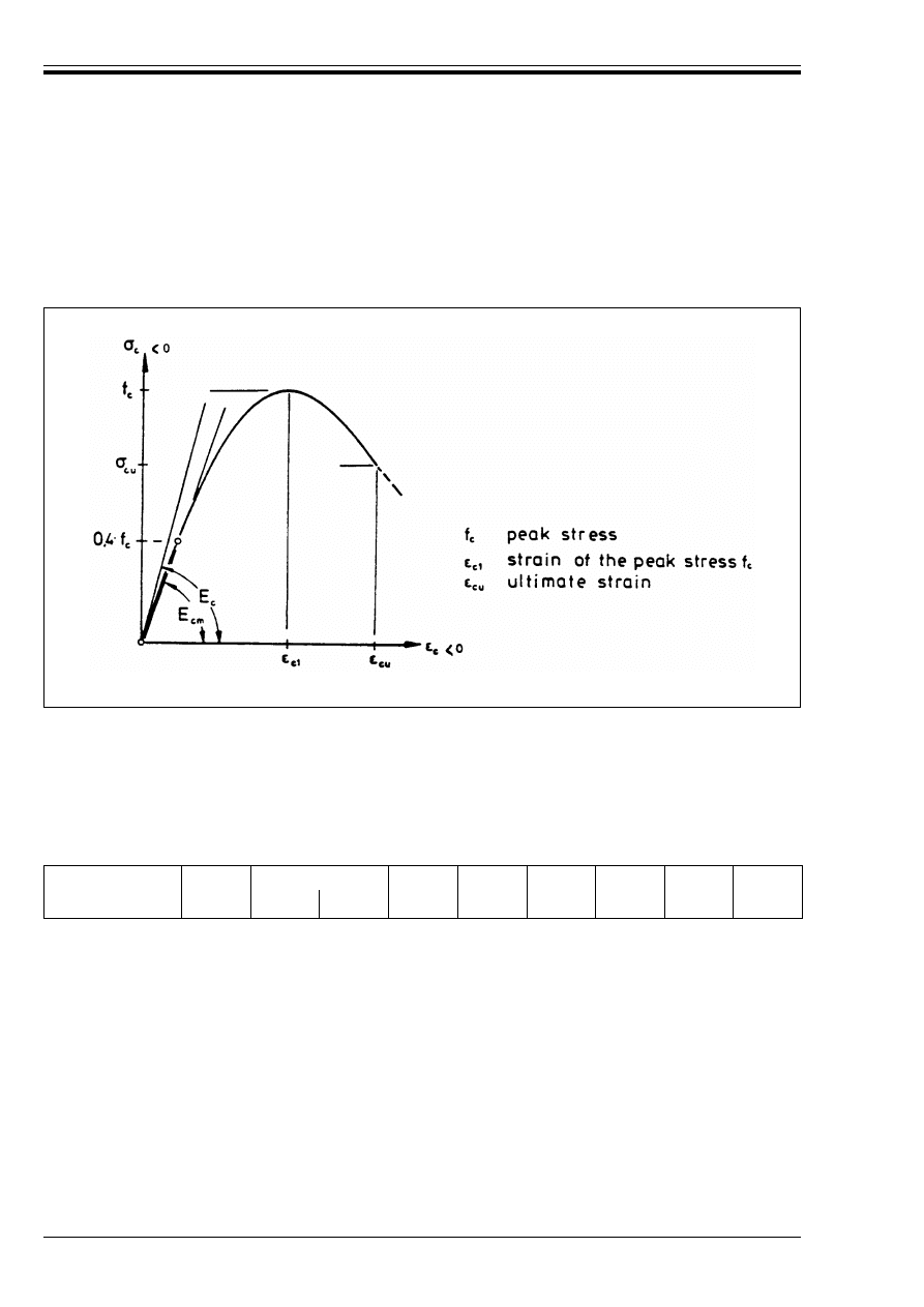
ENV 1992-1-1:1992
48
© BSI 12-1999
3.1.2.5.1 Stress-strain diagram
(1) The stress-strain diagram for concrete subjected to uniaxial compression is generally of the form shown
schematically in Figure 3.1.
(2) For the design calculations, suitable idealised stress-strain diagrams may be used. Such idealisations
are indicated in Section 4.2.1.3.3 of this code.
3.1.2.5.2 Modulus of elasticity
(1) The modulus of elasticity depends not only on the strength class of the concrete but also on the actual
properties of the aggregates used. (see 3.1.2.5(1) above).
(2) In the absence of those values or in cases where great accuracy is not required, an estimate of the mean
value of the secant modulus E
cm
can be obtained from Table 3.2 for a given concrete strength class. The
values in this Table are defined by B
c
= 0 and B
c
= 0,4 f
ck
(see Figure 3.1; B
c
: concrete compressive stress).
Table 3.2 — Values of the secant modulus of elasticity E
cm
(in kN/mm
2
)
(3) The values in Table 3.2 are based on the following equation:
They relate to concrete cured under normal conditions and made with aggregates predominantly consisting
of quarzite gravel. When deflections are of great importance, tests should be carried out on concrete made
with the aggregate to be used in the structure. In other cases experience with a particular aggregate,
backed by general test data, will often provide a reliable value for E
cm
, but with unknown aggregates, it
would be advisable to consider a range of values.
(4) As a rule, since the strength classes of concrete f
ck
correspond to a strength at an age of 28 days, the
values for E
cm
in Table 3.2 also relate to that same age. Where great accuracy is not required, E
cm
can also
be determined from Table 3.2 for a concrete age t other than 28 days. In this case, f
ck
is replaced by the
actual concrete strength at the time t.
3.1.2.5.3 Poisson’s ratio
P(1) For design purposes Poisson’s ratio for elastic strains may be taken equal to 0.2.
Figure 3.1 — Stress-strain diagram for uniaxial compression
Strength Class C
C12/15
C16/20
C20/25
C25/30
C30/37
C35/45
C40/50
C45/55
C50/60
E
cm
26
27.5
29
30.5
32
33.5
35
36
37
E
cm
= 9.5 (f
ck
+ 8)
1/3
(E
cm
in kN/mm
2
; f
ck
in N/mm
2
)
(3.5)
Licensed copy:Heriot Watt University, 20/04/2004, Uncontrolled Copy, © BSI
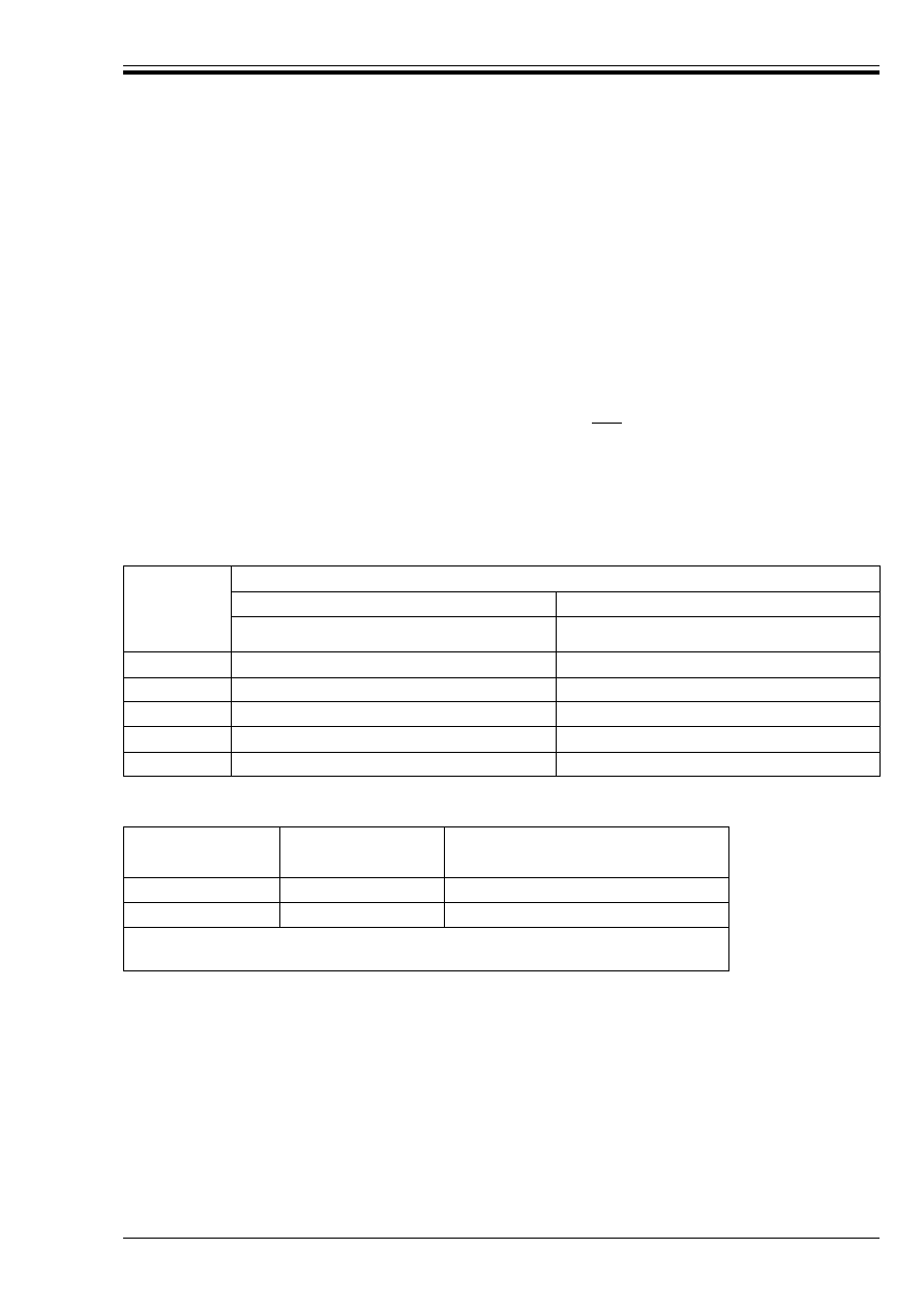
ENV 1992-1-1:1992
© BSI 12-1999
49
P(2) If cracking is permitted for concrete in tension, Poisson’s ratio may be assumed as zero.
3.1.2.5.4 Coefficient of thermal expansion
P(1) For design purposes, where thermal expansion is not of great influence, it may be taken equal
to 10 × 10
–6
/°C.
3.1.2.5.5 Creep and shrinkage
(1) Creep and shrinkage of the concrete depend mainly on the ambient humidity, the dimensions of the
element and the composition of the concrete. Creep is also influenced by the maturity of the concrete when
the load is first applied and on the duration and magnitude of the loading. Any estimation of the creep
coefficient Ì(t,t
o
), and of the shrinkage strain, (
cs
, should take these parameters into account.
(2) In cases where great accuracy is not required, the values given in Table 3.3 and Table 3.4 respectively
can be considered as final creep coefficient Ì(Z, t
o
) and the final shrinkage strain (
cs Z
of a normal
weight concrete subjected to a compressive stress not exceeding |0.45| f
ck
at the time to at first loading.
In Table 3.3, the creep coefficient Ì(Z, t
o
) is related to E
cm
, according to Table 3.2 and Equation 3.5. Where
greater accuracy is required, reference should be made to Appendix 1.
(3) The data given in Table 3.3 and Table 3.4 apply for a range of the average temperature of the concrete
between 10 °C and 20 °C. Therefore, seasonal variations of temperature between – 20 °C and + 40 °C can
be accepted. In the same way, variations in relative humidity around the average values given in Table 3.3
and Table 3.4 between RH = 20 % and RH = 100 % are acceptable.
Table 3.3 — Final creep coefficient Ì(
Z,t
o
) of normal weight concrete
Table 3.4 — Final shrinkage strains (
cs
Z
Z
(in o/oo) of normal
weight concrete
Linear interpolation between the values in Table 3.3 and Table 3.4 is permitted.
(4) The values of Table 3.3 and Table 3.4 apply to concrete having a plastic consistence of classes S2 and
S3 (see Clause 7.2.1 in ENV 206) when fresh. For concrete of other consistence the values have to be
multiplied by 0.70 (stiff consistence, S1) or 1.20 (soft consistence, S4).
(5) For concrete with superplasticizers, the consistence before adding the superplasticizers is used for the
evaluation of the creep and shrinkage coefficients as given in Table 3.3 and Table 3.4.
NOTE The following sections 3.2, 3.3 and 3.4 describe materials to be used in structural concrete for which CEN standards or
European approval documents are not yet available. A CEN Standard (EN 10080) is being prepared for reinforcement, and EN 10138
is being similarly prepared for prestressing steel. Work has not yet started on a CEN Standard for prestressing devices.
Age at loading
t
o
(days)
Notional size 2 A
c
/u (in mm)
50
150
600
50
150
600
Dry atmospheric conditions (inside)
(RH = 50 %)
Humid atmospheric conditions (outside)
(RH = 80 %)
1
5.5
4.6
3.7
3.6
3.2
2.9
7
3.9
3.1
2.6
2.6
2.3
2.0
28
3.0
2.5
2.0
1.9
1.7
1.5
90
2.4
2.0
1.6
1.5
1.4
1.2
365
1.8
1.5
1.2
1.1
1.0
1.0
Location of the
member
Relative humidity
Notional size 2A
c
/u (mm)
(%)
r 150
600
Inside
50
– 0.60
– 0.50
Outside
80
– 0.33
– 0.28
where: A
c
cross-sectional area of concrete
u perimeter of that area
Licensed copy:Heriot Watt University, 20/04/2004, Uncontrolled Copy, © BSI

ENV 1992-1-1:1992
50
© BSI 12-1999
3.2 Reinforcing steel
3.2.0 Notation (see also 1.6 and 1.7)
3.2.1 General
P(1) This section applies to bars, coiled rods and welded fabric, used as reinforcement in concrete
structures.
P(2) The requirements apply to the product in the condition in which it is delivered. In the case of coiled
rods, the requirements apply to the material after straightening.
(3) The methods of production, the specified characteristics, the methods of testing and the methods of
attestation of conformity are as defined in EN 10080 or other relevant documents for reinforcing materials
not covered by EN 10080.
P(4) Each product shall be clearly identifiable with respect to the classification system in 3.2.2.
P(5) Tensile strength (f
t
), yield stress (f
y
), the ratio of tensile strength to yield stress (f
t
/f
y
), the elongation
at maximum load ((
u
), and the projected rib factor (f
R
) shall all be appropriately specified in relevant
Standards and established by standard tests.
(6) For steels complying with this Code, yield stress, tensile strength, the ratio of tensile strength to yield
stress, the elongation at maximum load and the projected rib factor should be specified in terms of
characteristic values; these values are designated respectively f
yk
, f
tk
, (f
t
/f
y
)
k
, (
uk
, f
Rk
.
3.2.2 Classification and geometry
P(1) The products shall be classified according to:
i) Grade, denoting the value of the specified characteristic yield stress (f
yk
) in N/mm
2
.
ii) Class, indicating the ductility characteristics
iii) Size
iv) Surface characteristics
v) Weldability.
P(2) Each consignment shall be accompanied by a certificate containing all the information necessary for
its identification with regard to i)–v) in (1) above, and additional information where necessary.
P(3) The actual cross sectional area of the products shall not differ from their nominal cross sectional area
by more than the limits specified in relevant Standards.
P(4) In this code, two classes of ductility are defined (see 3.2.4.2):
10)
P(5) In this code two shapes of surface characteristics are defined (see 3.2.5.1);
— Ribbed bars, resulting in high bond action (as specified in EN 10080).
— Plain, smooth bars, resulting in low bond action.
f
R
Projected rib factor
f
Rk
Characteristic projected rib factor
f
0.2k
Characteristic 0.2 % proof-stress of reinforcement
f
t
Tensile strength of reinforcement
f
tk
Characteristic tensile strength of reinforcement
(
u
Elongation of reinforcement at maximum load
(
uk
Characteristic elongation of reinforcement at maximum load
— high
(H)
— normal (N)
10)
It is likely that, during the ENV period, a higher ductility steel will be introduced for use in seismic regions (Class S). Until
appropriate, design rules are developed for the use of this steel in non-seismic situations (dealing with redistribution, rotation
capacity, etc) it will be satisfactory to treat Class S steel as “high ductility”.
Licensed copy:Heriot Watt University, 20/04/2004, Uncontrolled Copy, © BSI

ENV 1992-1-1:1992
© BSI 12-1999
51
(6) For other types of bar, with other surface characteristics (ribs or indentations), reference should be
made to relevant documents, based on test data.
P(7) Surface characteristics of reinforcing steel with approximately circular cross section shall be indicated
by the value of the projected rib factor f
R
(see 3.2.5.1).
P(8) Welded fabric, used as reinforcing steel, shall comply with the dimensional requirements in relevant
Standards.
3.2.3 Physical properties
(1) The following mean values may be assumed:
— coefficient of thermal expansion: 10 × 10
–6
/°C.
3.2.4 Mechanical properties
3.2.4.1
Strength
P(1) The yield stress f
yk
and the tensile strength f
tk
are defined respectively as the characteristic value of
the yield load, and of the characteristic maximum load in direct axial tension, each divided by the nominal
cross sectional area.
(2) For products without a pronounced yield stress f
yk
, the 0,2 % proof stress f
0,2k
may be substituted.
P(3) The ratio of the actual yield stress f
y
to the specified characteristic yield stress f
yk
shall not exceed the
values specified in relevant Standards.
3.2.4.2
Ductility characteristics
P(1) The products shall have adequate ductility in elongation, as specified in relevant Standards.
(2) Adequate ductility in elongation may be assumed, for design purposes, if the products satisfy the
following ductility requirements:
High ductility: (
uk
> |5| %; value of (f
t
/f
y
)
k
> |1.08|
Normal ductility: (
uk
> |2.5| %; value of (f
t
/f
y
)
k
> |1.05|
In which (
uk
denotes the characteristic value of the elongation at maximum load (shown typically
in Figure 3.2).
High bond bars with diameters less than 6 mm should not be treated as having high ductility.
P(3) The products shall have adequate bendability for the anticipated use.
3.2.4.3
Modulus of elasticity
(1) A mean value of 200 kN/mm
2
may be assumed.
3.2.4.4
Fatigue
P(1) Where required, the products shall have adequate fatigue strength.
(2) For fatigue requirements for reinforcing steel, see Part 1E and relevant Standards.
— density
: 7 850 kg/m
3
Licensed copy:Heriot Watt University, 20/04/2004, Uncontrolled Copy, © BSI
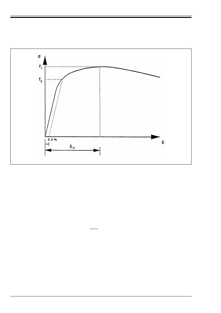
ENV 1992-1-1:1992
52
© BSI 12-1999
3.2.5 Technological properties
3.2.5.1
Bond and anchorage
P(1) The surface characteristics of ribbed bars shall be such that adequate bond is obtained with the
concrete, permitting the full force that is assumed in design, to be developed in the reinforcement.
(2) Ribbed bars, having a characteristic projected rib factor (f
Rk
) not less than that in EN 10080 may be
assumed to be high bond bars. Bars not satisfying these requirements should be treated as plain bars with
respect to bond unless they are defined according to (3) below. (See 5.2.2.2(1) and Table 5.3).
See also 3.2.2(6).
(3) The behaviour in bond of reinforcing steels with other surface shapes should be defined in relevant
Standards or technical approval documents.
P(4) The strength of the welded joints along the anchorage length of welded fabric shall be adequate.
(5) The strength of the welded joints of welded fabric may be assumed to be adequate if each welded joint
can withstand a shearing force not less than |30 %| of a force equivalent to the specified characteristic
yield stress times the nominal cross sectional area of the anchored wire.
3.2.5.2
Weldability
P(1) The products shall have weldability properties adequate for the anticipated use.
(2) Where required, and where the weldability is unknown, tests should be requested.
(3) Ductility characteristics, as specified in 3.2.4.2, should be maintained, when necessary, at critical
sections near to welds.
Figure 3.2 — Typical stress-strain diagram of reinforcing steel
Licensed copy:Heriot Watt University, 20/04/2004, Uncontrolled Copy, © BSI

ENV 1992-1-1:1992
© BSI 12-1999
53
3.3 Prestressing steel
(See note preceeding 3.2).
3.3.0 Notation (see also 1.6, 1.7)
3.3.1 General
P(1) This section applies to wires, bars and strands used as prestressing tendons in concrete structures.
P(2) The requirements apply to the product in the condition in which it is delivered.
(3) The methods of production, the specified characteristics, the methods of testing and the methods of
attestation of conformity are as defined in EN 10138 and other relevant Standards for prestressing
materials.
P(4) Each product shall be clearly identifiable with respect to the classification system in 3.3.2.
P(5) Tensile strength (f
p
), 0,1 % proof stress (f
p0,1
) and elongation at maximum load ((
u
) shall all be
appropriately specified in relevant Standards, and established by standard tests.
(6) For steels complying with this Code, tensile strength, 0.1 % proof stress, and elongation at maximum
load are specified in terms of characteristic values; these values are designated respectively f
pk
, f
p0.1k
and (
uk
.
3.3.2 Classification and geometry
P(1) The products (wires, strands and bars) shall be classified according to:
i) Grade, denoting the value of the 0,1 % proof stress (f
p0.1k
) and the value of the tensile strength (f
pk
)
in N/mm
2
.
ii) Class, indicating the relaxation behaviour
iii) Size
iv) Surface characteristics.
P(2) Each consignment shall be accompanied by a certificate containing all the information necessary for
its identification with regard to i)–iv) in (1) above and additional information where necessary.
P(3) The actual cross sectional area of the products shall not differ from their nominal cross sectional area
by more than the limits specified in the relevant standards.
P(4) There shall be no welds in wires and bars. Individual wires of strands may contain staggered welds
made only before cold drawing.
P(5) For coiled products, after uncoiling a length of wire or strand lying free on a flat surface, the maximum
bow height from a base line of specified length shall be less than the values specified in the relevant
standards.
P(6) In this Code, three classes of relaxation are defined (see 3.3.5.2);
Class 1: for wires and strands, high relaxation
Class 2: for wires and strands, low relaxation
Class 3: for bars.
P(7) Where required, surface characteristics of prestressing steel shall comply with EN 10138 or other
relevant Standards.
f
p
Tensile strength of prestressing steel
f
pk
Characteristic tensile strength of prestressing steel
f
p
0.1
0.1 % proof-stress of prestressing steel
f
p
0.1k
Characteristic 0.1 % proof-stress of prestressing steel
(
u
Elongation of prestressing steel at maximum load
(
uk
Characteristic elongation of prestressing steel at maximum load
Licensed copy:Heriot Watt University, 20/04/2004, Uncontrolled Copy, © BSI
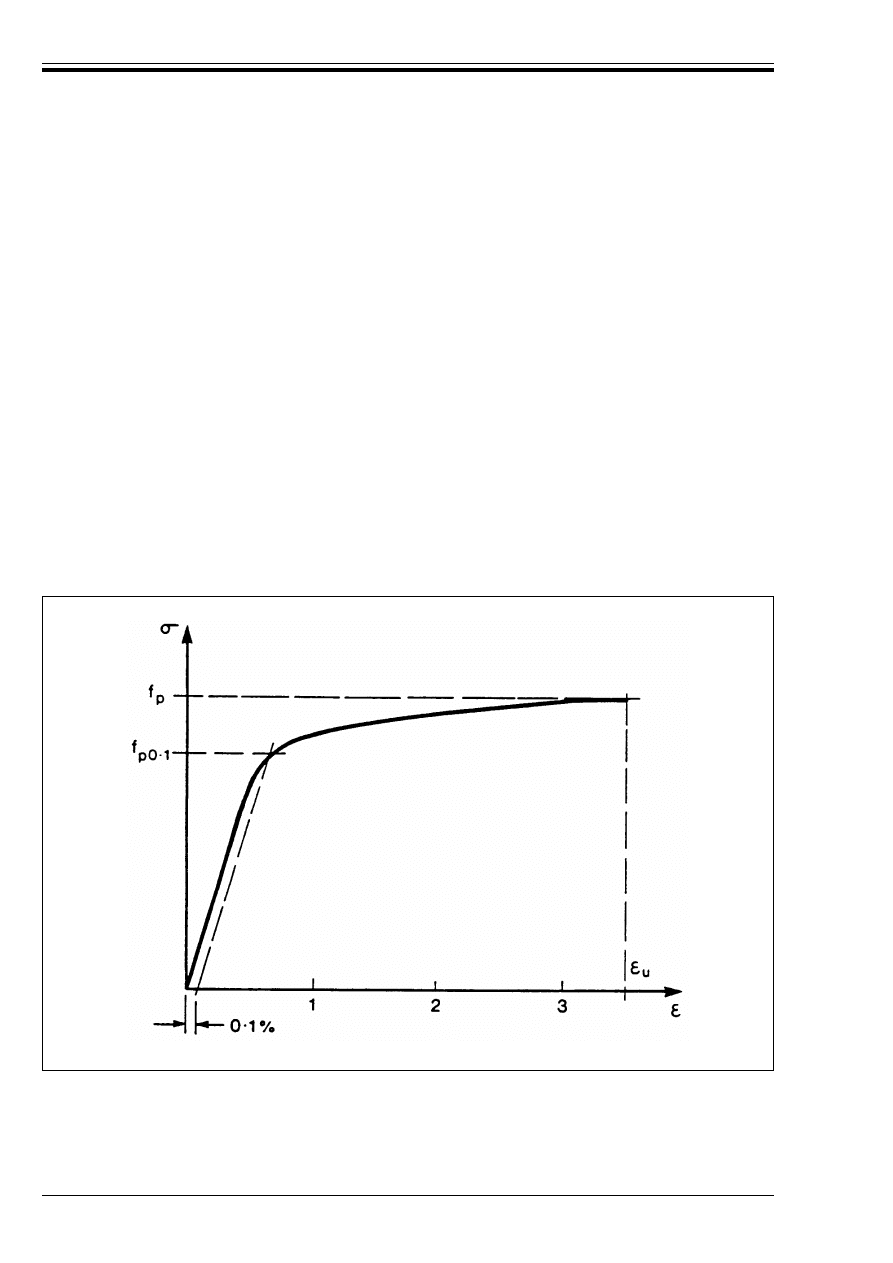
ENV 1992-1-1:1992
54
© BSI 12-1999
3.3.3 Physical properties
P(1) The following mean values may be assumed:
3.3.4 Mechanical properties
3.3.4.1
Strength
P(1) The 0,1 % proof stress (f
p 0.1k
) and the specified value of the tensile strength (f
pk
) are defined as the
characteristic value of the 0,1 % proof load and the characteristic maximum load in axial tension
respectively, divided by the nominal cross sectional area.
P(2) The ratio of the actual maximum load to the specified maximum load shall not exceed the values
specified in EN 10138 or other relevant Standards.
3.3.4.2
Stress-strain diagram
P(1) Stress-strain diagrams for the products, based on production data, shall be prepared and made
available by the producer as an annex to the certificate accompanying the consignment [see 3.3.2(2)].
3.3.4.3
Ductility characteristics
P(1) The products shall have adequate ductility in elongation, as specified in relevant Standards.
(2) Adequate ductility in elongation may be assumed if the products obtain the specified value of the
elongation at maximum load ((
uk
) given in EN 10138 (see Figure 3.3).
P(3) The products shall have adequate ductility in bending.
(4) Adequate ductility in bending may be assumed if the products satisfy the requirements for bendability
of the relevant standards.
— density
: 7 850 kg/m
3
— coefficient of thermal expansion: 10 × 10
–6
/°C.
Figure 3.3 — Typical stress-strain diagram of prestressing steel
Licensed copy:Heriot Watt University, 20/04/2004, Uncontrolled Copy, © BSI

ENV 1992-1-1:1992
© BSI 12-1999
55
3.3.4.4
Modulus of elasticity
(1) A mean value of 200 kN/mm
2
may be assumed for wires and bars. The actual value can range from 195
to 205 kN/mm
2
, depending on the manufacturing process.
(2) A value of 190 kN/mm
2
may be assumed for strand. The actual value can range from 175
to 195 kN/mm
2
, depending on the manufacturing process. Certificates accompanying the consignment
should give the appropriate value.
3.3.4.5
Fatigue
P(1) The products shall have adequate fatigue strength.
(2) For fatigue requirements of prestressing steel, see Part 1E and relevant Standards.
3.3.4.6
Multi-axial stresses
P(1) The behaviour of the products under multi-axial stresses shall be adequate.
(2) Adequate behaviour under multi-axial stresses may be assumed if the products satisfy the
requirements specified in the relevant standards.
3.3.5 Technological properties
3.3.5.1
Surface condition
P(1) The products shall be free from defects which could impair their performance as prestressing tendons.
(2) Longitudinal cracks need not be considered as defects if their depth is less than the values specified in
EN 10138 or other relevant standards.
3.3.5.2
Relaxation
P(1) The products shall be classified for relaxation purposes, according to the maximum percentages of loss
of stress.
3.3.5.3
Susceptibility to stress corrosion
P(1) The products shall have an acceptably low level of susceptibility to stress corrosion.
(2) The level of susceptibility to stress corrosion may be assumed to be acceptably low if the products
comply with the criteria specified in relevant Standards.
3.4 Prestressing devices
(See Note preceding 3.2)
3.4.1 Anchorages and couplers
3.4.1.1
General
P(1) This section applies to anchoring devices (anchorages) and coupling devices (couplers) for application
in post-tensioned construction, where:
i) anchorages are used to transmit the forces in tendons to the concrete in the anchorage zone;
ii) couplers are used to connect individual lengths of tendon to make continuous tendons.
P(2) The performance requirements, the methods of testing and the methods of attestation of conformity
shall be defined in relevant standards or in European Approval documents (to be developed).
P(3) In establishing performance requirements, consideration shall be given to:
i) the relative efficiency of the tendon anchorage/coupler assembly in comparing the actual value of the
failure load of the assembly with that of the tendon;
ii) the elongation of the anchored/coupled tendon at failure;
iii) the fatigue strength of the anchored/coupled tendon;
iv) the load which can be transferred by the anchorage to the concrete, taking account of the location of
the anchorage in the cross-section, the spacing between anchorages, the concrete strength and the
reinforcement in the anchorage zone.
P(4) Requirements for the use of anchorages and couplers, shall be defined in technical approval
documents. Detailing of anchorage zones shall comply with 4.2.3 and 5.4.
Licensed copy:Heriot Watt University, 20/04/2004, Uncontrolled Copy, © BSI

ENV 1992-1-1:1992
56
© BSI 12-1999
P(5) When defining test methods, consideration shall be given to two modes of testing;
i) Mode a: when components of known geometry and material specification have been taken at random
out of production or from stock.
ii) Mode b: when components have been selected by the producer of the components or when prototype
anchorages or couplers are to be tested.
3.4.1.2
Mechanical properties
3.4.1.2.1 Anchored tendons
P(1) Tendon-anchorage assemblies and tendon-coupler assemblies shall have strength, elongation and
fatigue characteristics sufficient to meet the basic requirements of Chapter 2.
(2) This may be assumed if:
i) The geometry and material characteristics of the anchorage and coupler components are such that
their premature failure is precluded.
ii) The elongation at failure of the assemblies is not excessive.
iii) Tendon-anchorage assemblies are not located in otherwise highly-stressed zones.
For the fatigue requirements of anchorages and couplers, see relevant Approval documents.
3.4.1.2.2 Anchorage devices and anchorage zones
P(1) The strength of the anchorage devices and zones shall be adequate for the transfer of the tendon force
to the concrete and the formation of cracks in the anchorage zone does not impair the function of the
anchorage.
(2) This may be assumed if:
i) The strength of the anchorage devices exceeds the characteristic breaking load of the tendon, either
under static loading conditions or a limited number of load cycles.
ii) The detailing provisions of this Code are met.
3.4.2 Ducts and sheaths
3.4.2.1
General
P(1) This section applies to post-tensioned concrete construction where the tendons are tensioned in
internal ducts.
P(2) For bonded tendons, where the ducts are grouted after tensioning, the shape (profile) of the duct shall
permit the proper transfer of forces from the tendons to the concrete.
P(3) The performance requirements, the methods of testing and the methods of attestation of conformity
shall be defined in relevant standards.
P(4) Requirements covering the use of ducts and sheaths shall be defined in technical approval documents.
(5) Sheaths should consist of adequate materials as specified in relevant Standards (to be drafted).
4 Section and member design
Based on the design data for materials in 4.2, Chapter 4.3 gives provisions for the ultimate limit states, to
satisfy the fundamental requirements of Chapter 2. Similarly, Chapter 4.4 covers the serviceability limit
states. In parallel to design in accordance with these Chapters, which are concerned mainly with the
internal forces and moments evaluated by the procedures given in Chapter 2.5, consideration shall also be
given to durability. Chapter 4.1 gives the necessary provisions. Requirements on the production and
control of concrete are given in ENV 206.
Licensed copy:Heriot Watt University, 20/04/2004, Uncontrolled Copy, © BSI

ENV 1992-1-1:1992
© BSI 12-1999
57
4.1 Durability requirements
4.1.0 Notation (See also 1.6 and 1.7)
4.1.1 General
P(1) The requirement of an adequately durable structure is met if, throughout its required life, a structure
fulfils its function with respect to serviceability, strength and stability without significant loss of utility or
excessive unforeseen maintenance.
P(2) To provide the required overall durability, as defined in P(1) above, the intended use of the structure
shall be established, together with the load specifications to be considered. The required life of the structure
and the maintenance programme shall also be considered, in assessing the level of protection required.
P(3) Durability may be affected both by direct actions and also by consequential indirect effects inherent
in the performance of the structure (e.g. deformations, cracking, water absorption, etc). The possible
significance of both direct and indirect effects shall be considered.
(4) For most buildings, the general provisions in this Code will ensure a satisfactory life. However, the
required level of performance — and its duration — should be considered consciously, at an early stage in
the design. Modifications to the recommended measures may be required in certain circumstances, e.g. for
temporary or monumental structures, or for structures subjected to extreme or unusual actions (either
direct or indirect effects — see P(3) above).
4.1.2 Actions
4.1.2.1
General
P(1) Actions shall be assessed in accordance with the definitions given in 2.2.2 and based on values given
in appropriate international or national codes.
In special cases, it may be necessary to consider modification of these values to meet particular durability
requirements.
4.1.2.2
Environmental conditions
P(1) Environment, in this context, means those chemical and physical actions, to which the structure as a
whole, the individual elements, and the concrete itself is exposed, and which results in effects not included
in the loading conditions considered in structural design.
(2) For the design of normal buildings, environmental conditions should be classified in accordance
with Table 4.1, to establish the overall level of protection required in accordance with the provisions of
ENV 206.
(3) In addition, it may be necessary to consider certain forms of aggressive or indirect action individually
(see 4.1.2.3, 4.1.2.4, 4.1.2.5).
4.1.2.3
Chemical attack
P(1) The effects of chemical attack shall be considered in design.
P(2) Consideration shall be given to the effects of chemical attack both on the concrete and any embedded
metal.
(3) Chemical attack may arise from:
— the use of the building (storage of liquids, etc);
— an aggressive environment (see Table 4.1 and ENV 206, Clause 6.2);
— contact with gases or solutions of many chemicals, but usually from exposure to acidic solutions or to
solutions of sulphate salts (see ENV 206, Table 3 and ISO 9690);
— chlorides contained in the concrete (see 5.5 in ENV 206 for the permitted maxima);
d
g
Largest nominal maximum aggregate size
%h
Tolerance on cover to reinforcement (difference between minimum and nominal cover)
Ì
Diameter of a reinforcing bar, diameter of a tendon or of a prestressing duct
Ì
n
Equivalent diameter of a bundle of reinforcing bars
Licensed copy:Heriot Watt University, 20/04/2004, Uncontrolled Copy, © BSI

ENV 1992-1-1:1992
58
© BSI 12-1999
— reactions between the materials in the concrete (e.g. alkali-aggregate reaction, see 5.7 in ENV 206
and National Standards).
— (4) For most buildings, adverse chemical reactions can be avoided by adopting an appropriate material
specification, e.g. the provisions in ENV 206, to achieve a dense impermeable concrete with appropriate
mix ingredients and properties (see Table 3, ENV 206). In addition, adequate cover is required to protect
the reinforcement (see 4.1.3.3).
4.1.2.4
Physical attack
P(1) The effects of physical attack shall be considered in design.
(2) Physical attack can occur because of:—
— abrasion (see 7.3.1.4 in ENV 206);
— freeze-thaw action (see ENV 206, Table 3);
— water penetration (see Table 3 and 7.3.1.5 in ENV 206).
(3) For most buildings, physical attack can be resisted through an appropriate material specification, e.g.
the provisions of ENV 206, combined with an appropriate limitation of cracking under the relevant load
combination (see 4.4.2).
4.1.2.5
Consequential indirect effects
P(1) Deformation of the structure as a whole, of individual structural elements or non-load bearing
elements (e.g. due to imposed loads, temperature, creep, shrinkage, micro-cracking, etc.) can lead to
consequential indirect effects, and these shall be considered in design.
(2) For most buildings, the influence of indirect effects can be accommodated by complying with general
requirements, given elsewhere in this Code, for durability, cracking, deformation, detailing, — and for
strength, stability and robustness of the structure as a whole. Additionally, consideration may have to be
given to the following:—
— minimising deformation and cracking due to time-dependent factors (e.g. early-age movement, creep,
shrinkage, etc) — see 3.1;
— minimising restraints due to deformation (e.g. by the provision of bearings or joints, while ensuring
that these do not permit the ingress of aggressive agents);
— if restraints are present, ensuring that any significant effects are taken into account in design.
4.1.3 Design
4.1.3.1
General
P(1) Early in the design process, the effects, and possible significance, of the actions in 4.1.2 shall be
considered in relation to the durability requirement in 4.1.1.
(2) For most buildings, reference should be made to the design criteria in 4.1.3.2 and to the requirements
for concrete cover to reinforcement in 4.1.3.3 and to the general material and construction factors in 4.1.4
and 4.1.5.
(3) Other factors to be considered in design and detailing, in order to achieve the required level of
performance, should include the following:—
— the adoption of a structural form which will minimise the uptake of water or exposure to moisture.
— the size, shape and design details of exposed elements or structures should be such as to promote good
drainage and to avoid run off or standing pools of water. Care should be taken to minimise any cracks
that may collect or transfer water. In the presence of cracks crossing a complete section and likely to
transport water containing chlorides, additional protective measures (coated bars, coatings, etc.) may be
necessary.
— attention, in design and detailing, to the different aspects of indirect effects (see 4.1.2.5);
— for most components in buildings, resistance to reinforcement corrosion is provided by having an
adequate cover of low-permeability, good-quality concrete (see 4.1.3.3 and ENV 206). For the more
severe conditions of exposure (see Table 4.1), consideration may need to be given to protective barriers
either to the concrete surface or to the reinforcement.
Licensed copy:Heriot Watt University, 20/04/2004, Uncontrolled Copy, © BSI

ENV 1992-1-1:1992
© BSI 12-1999
59
4.1.3.2
Design criteria
P(1) To produce a durable concrete, the requirements of chapters 3–7, shall be met, together with those of
ENV 206 — while considering local conditions, materials and practices.
P(2) For reinforced concrete corrosion protection to reinforcement shall be provided by compliance with the
requirements contained in the following clauses:
P(3) For prestressed concrete, in addition to the requirements in P(1) and P(2) above, the prestressing steel
shall be protected from all aggressive actions.
(4) For exposure classes 1–4, prestressed sections should be checked for cracking in accordance
with 4.4.2.1(7) and 4.4.2.2(5) – (8).
4.1.3.3
Concrete cover
P(1) The concrete cover is the distance between the outer surface of the reinforcement (including links and
stirrups) and the nearest concrete surface.
P(2) A minimum concrete cover shall be provided in order to ensure:
— the safe transmission of bond forces (see Chapter 5);
— that spalling will not occur;
— an adequate fire resistance (see Part X);
— the protection of the steel against corrosion (see P(3) below and ENV 206).
P(3) The protection of reinforcement against corrosion depends upon the continuing presence of a
surrounding alkaline environment provided by an adequate thickness of good quality, well-cured concrete.
The thickness of cover required depends both upon the exposure conditions and on the concrete quality.
P(4) The minimum concrete cover required for the criterion in P(3) above shall first be determined. This
shall be increased by an allowance (%h) for tolerances, which is dependent on the type and size of structural
element, the type of construction, standards of workmanship and quality control, and detailing practice.
The result is the required nominal cover which shall be specified on the drawings.
(5) To transmit bond forces safely, and to ensure adequate compaction, the concrete cover, to the bar or
tendon being considered, should never be less than:
— Ì or Ì
n
— or (Ì + 5 mm) or (Ì
n
+ 5 mm) if d
g
> 32 mm
where:
(6) The minimum concrete cover to all reinforcement including links and stirrups should not be less than
the appropriate values given in Table 4.2, for the relevant exposure class defined in Table 4.1.
(7) Where surface reinforcement is used (see 5.4.2.4), the cover should either comply with (6) above, or
special protective measures should be taken (e.g. protective coatings).
(8) The allowance (%h) for tolerances will usually be in the range |0 mm r %h r 5 mm|, for precast
elements, if production control can guarantee these values and if this is verified by quality control. The
allowance will be in the range |5 mm r %h r 10 mm| for insitu reinforced concrete construction.
Additional rules for construction and workmanship (including tolerances) are given in chapter 6.
4.4.1
stress conditions
4.4.2
cracking
4.4.3
deformation
4.1 (and ENV 206)
general durability requirements
4.1.3.3
concrete cover
Chapter 5
reinforcement detailing.
Ì
is the diameter of the bar, diameter of a tendon or of the duct (post-tensioning)
Ì
n
is the equivalent diameter for a bundle
d
g
is the largest nominal maximum aggregate size.
Reference should also be made to 5.4 in ENV 206.
Licensed copy:Heriot Watt University, 20/04/2004, Uncontrolled Copy, © BSI

ENV 1992-1-1:1992
60
© BSI 12-1999
(9) For concrete cast against uneven surfaces, the minimum covers given in Table 4.2 should generally be
increased by larger allowances for tolerances. For example, for concrete cast directly against the earth,
the minimum cover should be greater than |75 mm|; for concrete cast against prepared ground (including
blinding) the minimum cover should be greater than |40 mm|. surfaces having design features, such as
ribbed finishes or exposed aggregate, also require increased cover.
(10) The required minimum covers given in Table 4.2, as modified to allow for tolerances, may be
insufficient for fire protection. Particular requirements for fire resistance are given in separate
documents.
(11) For pre-tensioned members, the minimum cover should not be less than 2 Ì, where Ì is the diameter
of a tendon. Where ribbed wires are used, the minimum cover should not be less than 3 Ì.
(12) For post-tensioned members, the minimum cover is to the duct. The cover should be not less than the
diameter of the duct. For rectangular ducts, the cover should be not less than the lesser dimension of the
duct cross-section nor half the greater dimension.
Table 4.1 — Exposure classes related to environmental conditions
Exposure class
Examples of environmental conditions
1
dry environment
interior of buildings for normal habitation or offices
a
2
humid
environment
a
without
frost
— interior of buildings where humidity is high (e.g. laundries)
— exterior components
— components in non-aggressive soil and/or water
b
with frost
— exterior components exposed to frost
— components in non-aggressive soil and/or water and exposed to frost
— interior components when the humidity is high and exposed to frost
3
humid environment with frost
and de-icing salts
interior and exterior components to frost and de-icing agents
4
seawater
environment
a
without
frost
— components completely or partially submerged in seawater, or in the
splash some
— components in saturated salt air (coastal area)
b
with frost
— components partially submerged in seawater or in the splash zone and
exposed to frost
— components in saturated salt air and exposed to frost
The following classes may occur alone or in combination with the above classes:
5
aggressive
chemical
environment
b
a
— slightly aggressive chemical environment (gas, liquid or solid)
— aggressive industrial atmosphere
b
moderately aggressive chemical environment (gas, liquid or solid)
c
highly aggressive chemical environment (gas, liquid or solid)
a
This exposure class is valid only as long as during construction the structure or some of its components is not exposed to more
severe conditions over a prolonged period of time
b
Chemically aggressive environments are classified in ISO/DP 9690. The following equivalent exposure conditions may be
assumed:
Exposure class 5 a: ISO classification A1G, A1L, A1S
Exposure class 5 b: ISO classification A2G, A2L, A2S
Exposure class 5 c: ISO classification A3G, A3L, A3S
Licensed copy:Heriot Watt University, 20/04/2004, Uncontrolled Copy, © BSI

ENV 1992-1-1:1992
© BSI 12-1999
61
Table 4.2 — Minimum cover requirements for normal weight concrete
1)
4.1.4 Materials
P(1) Materials shall comply with the requirements of appropriate international or national standards. The
choice of materials shall be made, taking account of the environmental conditions including any aggressive
actions. These should be considered in conjunction with other factors such as design and detailing,
standards of workmanship and construction, and intended maintenance regimes — to produce the required
level of performance for the structure throughout its service life.
(2) For concrete the requirements should generally be in accordance with ENV 206. These requirements
relate to the constituents and composition of the mix and to the processes involved in mixing,
transporting, placing, compacting and curing the concrete in the structure.
(3) For reinforcement, the requirements of 3.2 apply.
(4) For prestressing steel, the requirements of 3.3 apply.
(5) For anchorage devices, the requirements of 3.4 apply. For exposure classes 2 – 5, any anchorage or
fixing device which is not fully embedded in the concrete may have to be protected against corrosion by
special measures.
(6) Other materials may be used, provided that full account is taken of their effects on design
requirements and that there are satisfactory data on their suitability and quality.
4.1.5 Construction
P(1) The standard of workmanship on site shall be such as to ensure that the required durability of the
structure will be obtained. The combination of materials and procedures used in making, placing and
curing the concrete shall be such as to achieve satisfactory resistance to aggressive media for both concrete
and steel.
P(2) During construction, adequate measures shall be taken, by means of supervision and quality control,
to ensure that the required properties of the materials and standards of workmanship are achieved.
(3) The requirements for workmanship are given in chapter 6 and in ENV 206.
4.2 Design data
4.2.1 Concrete
4.2.1.0 Notation (See also 1.6, 1.7)
Exposure class, according to Table 4.1
1
2a
2b
3
4a
4b
5a
5b
5c
3)
2)
Minimum
cover (mm)
Reinforcement
Prestressing
steel
NOTES
1 In order to satisfy the provisions of 4.1.3.3 P(3), these minimum values for cover should be associated with particular concrete
qualities, to be determined from Table 3 in ENV 206.
2 For slab elements, a reduction of 5 mm may be made for exposure classes 2–5.
3 A reduction of 5 mm may be made where concrete of strength class C40/50 and above is used for reinforced concrete in exposure
classes 2a–5b, and for prestressed concrete in exposure classes 1–5b. However, the minimum cover should never be less than that
for Exposure Class 1 in Table 4.2.
4 For exposure class 5c, the use of a protective barrier, to prevent direct contact with the aggressive media, should be provided.
E
c,nom
Either the mean value of E
cm
(Table 3.2) or the corresponding design value E
cd
(Equation 4.1)
F
c
Force due to the compression block at a critical section at the ultimate limit state
F
s
Force in the tension reinforcement at a critical section at the ultimate limit state
15
20
25
40
40
40
25
30
40
25
30
35
50
50
50
35
40
50
Licensed copy:Heriot Watt University, 20/04/2004, Uncontrolled Copy, © BSI

ENV 1992-1-1:1992
62
© BSI 12-1999
4.2.1.1
General
P(1) Data on material properties in this section are either representative values, corresponding to the
relevant strength class of concrete, or are idealizations suitable for design purposes.
If not stated otherwise, the properties with regard to strength shall be represented by their characteristic
values (see 3.1.2.2).
P(2) Design data for concrete shall be derived from measured or known properties. These properties shall
be determined by means of standard tests.
P(3) Design shall be based on a specified strength class of concrete (see 3.1.2.4).
(4) The applicability of the idealizations and design assumptions of this Code for concrete with strength
classes less than C 12/15 or higher than C 50/60 should be investigated.
(5) in the absence of more accurate data or when great accuracy is not required the rules given in the
following clauses may be used as a general approximation.
(6) Design data on plain concrete, lightweight concrete, high strength concrete, and concrete subject to
steam curing are given separately in relevant Appendices or Parts of this Code. The applicability of the
idealizations given in this section should be investigated for those cases.
4.2.1.2
Physical properties
a) Density
The density of normal weight concrete may be assumed to be:
@ = 2 400 kg/m
3
for plain (unreinforced) concrete;
@ = 2 500 kg/m
3
for reinforced or prestressed concrete with normal percentages of reinforcement.
b) Poisson’s ratio
Section 3.1.2.5.3 applies.
c) Coefficient of thermal expansion
Section 3.1.2.5.4 applies.
4.2.1.3
Mechanical properties
4.2.1.3.1 Strength
(1) Characteristic values for defined strength classes of concrete may be taken from Table 3.1 (see 3.1.2.4).
(2) For each strength class of concrete three values of concrete tensile strength are to be distinguished
[see 3.1.2.3(4)]. They should be applied appropriately, depending on the problem being considered.
4.2.1.3.2 Modulus of elasticity
(1) Section 3.1.2.5.2 applies.
4.2.1.3.3 Stress-strain diagrams
(1) The actual stress-strain diagram of concrete, obtained by experiment as described in 3.1.2.5.1, may be
replaced by an idealized diagram.
(2) A distinction is made between diagrams for structural analysis [(3)–(8) below] and those for
cross-section design [(9)–(12) below].
k
Coefficient used in defining the shape of the stress-strain diagram of concrete
(k = 1.1 E
c,nom
× (
c1
/f
c
)
!
Reduction factor for concrete compressive strength
(
c1
Compressive strain in the concrete at the peak stress f
c
(
cu
Ultimate compressive strain in the concrete
n
Ratio for the physical description of the stress-strain diagram for concrete (Equation 4.2
and Figure 4.1)
Licensed copy:Heriot Watt University, 20/04/2004, Uncontrolled Copy, © BSI
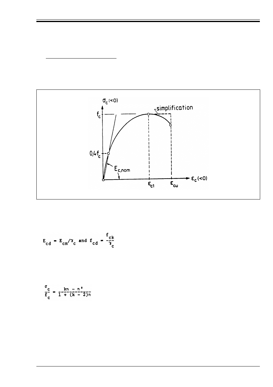
ENV 1992-1-1:1992
© BSI 12-1999
63
a) Diagrams for structural analysis
(3) For non-linear or plastic analysis (see Appendix 2), or for the calculation of second order effects
(see Appendix 3), stress-strain diagrams for short-term loads, as shown diagrammatically in Figure 4.1,
may be applied. These are characterised by the modulus of elasticity E
c,nom
, the concrete compressive
strength f
c
, and the strain (
c1
at the peak stress f
c
. (Compressive stress and strain both taken as negative).
(4) For the relevant values of the modulus of elasticity E
c,nom
and the compressive strength f
c
, either
— mean values E
cm
(see 3.1.2.5.2) and f
cm
[see equation (4.3) below]
or
— design values
are applicable according to the relevant clauses in sections 2.5.3 and 4.3.5. In equation (4.1), E
cm
and f
ck
refer to the mean values of modulus of elasticity and characteristic strength respectively. *
c
is the partial
safety factor for concrete (see 2.3.3.2 and A.3.1).
(5) The B
c
– (
c
relationship given in Figure 4.1 for short-term loading, can be expressed by the following
function:
Equation (4.2) is valid for 0 > (
c
> (
cu
Figure 4.1 — Schematic stress-strain diagram for structural analysis [4.2.1.3.3(5)–(7)]
(4.1)
(4.2)
where:
n
= (
c
/(
c1
((
c
and (
c1
are both < 0)
(
c1
= – 0,0022 (strain of the peak compressive stress f
c
)
k
= (1.1 E
c,nom
) . (
c1
/f
c
(f
c
introduced as – f
c
)
E
c,nom
denotes either the mean value E
cm
of the longitudinal modulus of deformation (Table 3.2)
or the corresponding design value E
cd
(see paragraph (4) above).
Licensed copy:Heriot Watt University, 20/04/2004, Uncontrolled Copy, © BSI
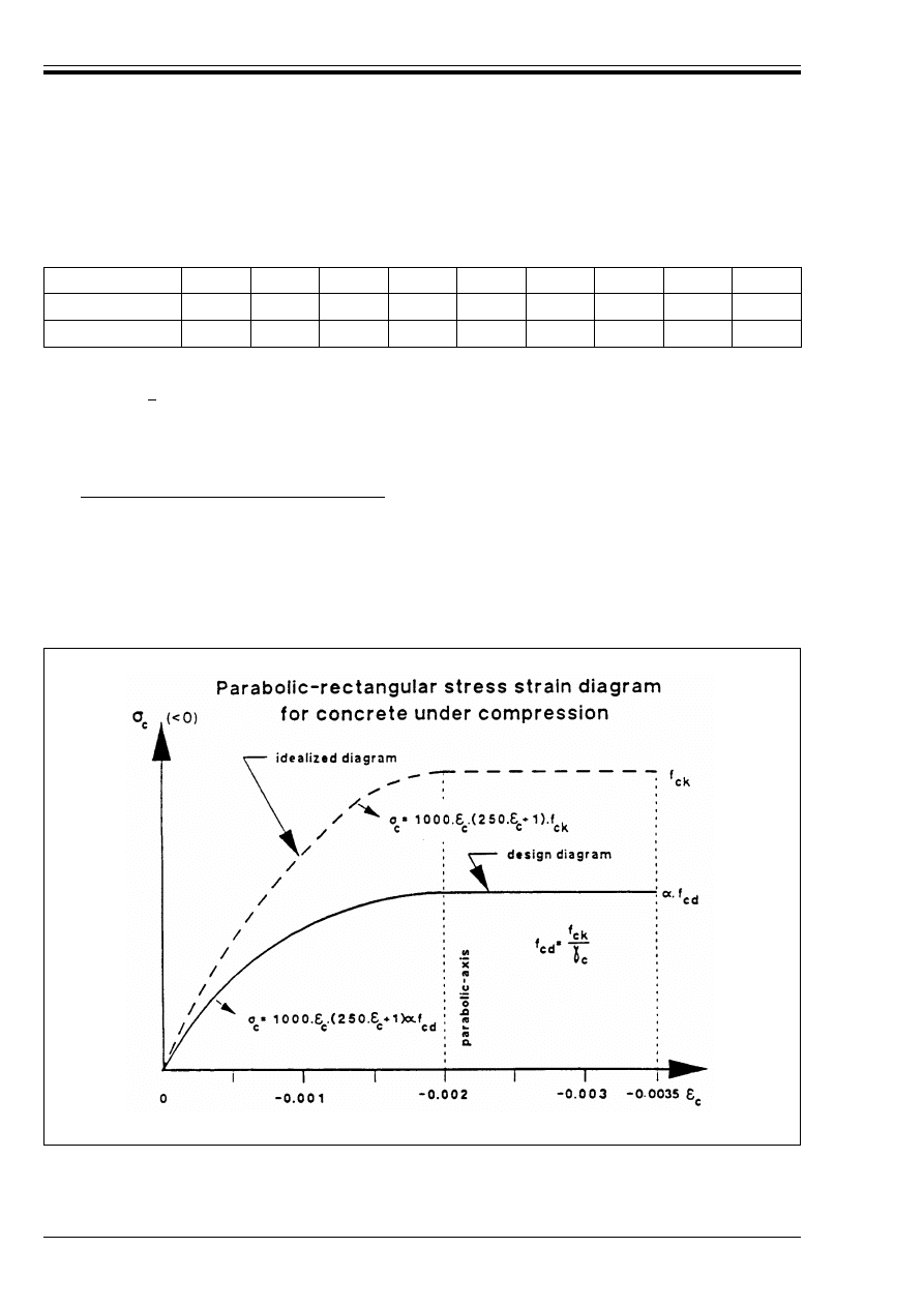
ENV 1992-1-1:1992
64
© BSI 12-1999
where (
cu
denotes the ultimate strain in the extreme fibre of the concrete in compression.
(6) For a compression zone of rectangular shape, the mean values for (
cu
related to the concrete strength
class are given in Table 4.3.
Table 4.3 — Nominal values of (
cu
(rectangular sections)
In the derivation of Table 4.3, it has been assumed that
(7) For simplification, a constant value B
c
= f
c
may be adopted in the range (
c1
> (
c
> (
cu
(see Figure 4.1)
(8) Other idealized stress-strain diagrams may be used (e.g. bi-linear), provided they are effectively
equivalent to the one described in (3) and (4).
b) Stress distribution for cross-section design
(9) The preferred idealization for cross-section design is the parabolic rectangular one, given in
Figure 4.2.
In this diagram (
cu
max is taken as 3.5°/oo, and compressive stress and strain are taken as negative.
(10) Other idealized stress-diagrams may be used, provided they are effectively equivalent to the
parabolic-rectangular diagram, with regard to the shape of the compression zone in the cross-section (e.g.,
the bi-linear diagram in Figure 4.3).
Strength class
12/15
16/20
20/25
25/30
30/37
35/45
40/50
45/55
50/60
f
cm
N/mm
2
20
24
28
33
38
43
48
53
58
(
cu
10
–3
– 3.6
– 3.5
– 3.4
– 3.3
– 3.2
– 3.1
– 3.0
– 2.9
– 2.8
f
cm
= f
ck
+ |8| (N/mm
2
)
(4.3)
Figure 4.2 — Parabolic — rectangular stress-strain diagram for concrete in compression
Licensed copy:Heriot Watt University, 20/04/2004, Uncontrolled Copy, © BSI
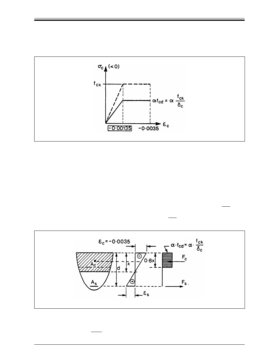
ENV 1992-1-1:1992
© BSI 12-1999
65
(11) The design concrete strength is defined by
The design diagram is derived from the chosen idealized diagram by means of a reduction of the stress
ordinate of the idealized diagram by a factor !/*
c
, in which
The additional reduction factor ! for sustained compression may generally be assumed to be |0.85|.
(12) A rectangular stress distribution (as given in Figure 4.4) may be assumed. The !-factor as given for
the idealized diagram is valid, except that it should be reduced to |0.80| when the compression zone
decreases in width in the direction of the extreme compression fibre.
4.2.1.4
Time dependent behaviour
(1) The data given in Table 3.3 are mean values, valid in the temperature ranges of 3.1.2.5.5(3), and may
be assumed to represent the final coefficients of creep and shrinkage for concrete, where compressive
stresses do not exceed B
c
= |0.45 f
ck
|.
Figure 4.3 — Bi-linear stress-strain diagram for concrete
(4.4)
*
c
is the partial coefficient for concrete (see 2.3.3.2)
!
is a coefficient taking account of long term effects on the compressive strength and of
unfavourable effects resulting from the way the load is applied.
Figure 4.4 — Rectangular diagram
f
cd
f
ck
*
c
-------
=
Licensed copy:Heriot Watt University, 20/04/2004, Uncontrolled Copy, © BSI

ENV 1992-1-1:1992
66
© BSI 12-1999
(2) For detailed calculations involving loss of prestress, the general information in sections 3.1, 2.5.4
and 2.5.5 may be used where appropriate, in following the procedures set out in 4.2.3.5.5.
4.2.2 Reinforced concrete
4.2.2.0
Notation
For notation used in this section, see 1.6 and 1.7.
4.2.2.1
Reinforcing steel: general
P(1) Data on material properties given in this section are either representative values, corresponding to
the relevant steel grade specified in appropriate Standards, or are idealisations suitable for design
purposes.
(2) In general, the properties specified are those given in 3.2.1(5) and established in EN 10080 or other
appropriate Standards.
P(3) Unless stated otherwise, design shall be based on a specified grade, represented by its characteristic
yield stress (f
yk
).
(4) All types of reinforcing steel specified in 3.2, which satisfy the mechanical, physical and technological
requirements of EN 10080 or other relevant Standards, may generally be used in design, in accordance
with 4.2.2.2–4.2.2.4, unless greater accuracy is required.
4.2.2.2
Physical properties of reinforcing steel
(1) The values given in 3.2.3 may be used as design data. They may be assumed to be valid in the range
from – 20 °C to 200 °C.
4.2.2.3
Mechanical properties of reinforcing steel
4.2.2.3.1 Strength
P(1) For all types of steel, the values for (
uk
, f
yk
, (f
t
/f
y
)
k
and f
tk
shall be defined.
(2) Values for these properties and for defined types and grades of steel may be taken from EN 10080. For
other types of steel, these properties should be established by testing.
(3) If not specified otherwise, the yield stress and the ultimate strength may be assumed to be equal in
tension and in compression, for design purposes.
(4) Design calculations may be based on the nominal size and the nominal cross-sectional area of the
reinforcing steel.
4.2.2.3.2 Stress-strain diagram
P(1) The general ductility requirements shall be in accordance with 3.2.4.2, and as specified in relevant
Standards.
(2) For overall analysis, the idealised bi-linear diagram in Figure 4.5 may generally be used. This diagram
is valid for temperatures from – 20° to 200 °C.
Licensed copy:Heriot Watt University, 20/04/2004, Uncontrolled Copy, © BSI
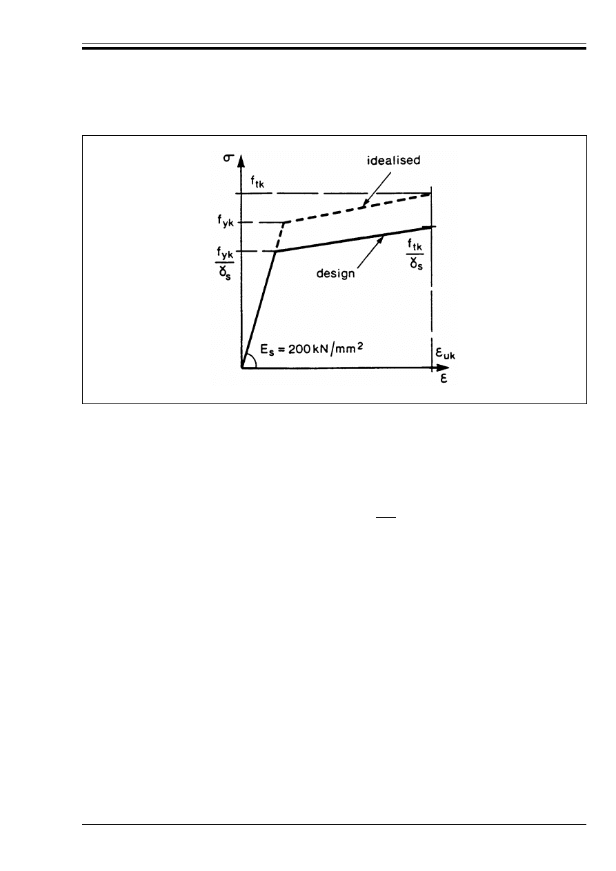
ENV 1992-1-1:1992
© BSI 12-1999
67
(3) Figure 4.5 may be modified, e.g. with a flatter or horizontal top branch, for local verifications and
section design.
(4) Design values are derived from the idealised characteristic diagram, by dividing by *
s
, the partial
factor for reinforcing steel (see 2.3.3).
(5) For section design, either of the following assumptions may be made:
— a horizontal top branch to the design curve in Figure 4.5, i.e. the stress in the reinforcement is limited
to f
yk
/*
s
, with no limit to the steel strain, although in some cases it may be convenient to assume a limit.
— an inclined top branch, with the steel strain limited to |0.01|.
4.2.2.3.3 Fatigue
(1) For fatigue requirements for reinforcing steel, see Part 1E.
4.2.2.4
Technological properties of reinforcing steel
4.2.2.4.1 Bond and anchorage
P(1) Bond and anchorage properties shall be derived from the shape of the surface characteristics of the
bars and/or from the strength of welded joints of welded fabric.
(2) Bond requirements should comply with 5.2.2.
(3) Anchorage requirements should comply with 5.2.3–5.2.5.
4.2.2.4.2 Weldability (see 3.2.5.2)
(1) Reinforcing steel which complies with EN 10080 may be assumed to be weldable.
4.2.3.0
Notation (see also 1.6, 1.7 and 2.5.4.0)
Figure 4.5 — Design stress-strain diagram for reinforcing steel
F
px
Ultimate resisting force provided by the prestressing tendons in a cracked anchorage zone
[Equation (4.14)]
k
Unintentional angular displacement (per unit length) related to the profile of the tendons
l
ba
Anchorage length over which the ultimate tendon force F
pu
in pretensioned members is
fully transmitted to the concrete
l
bp
Transmission length, over which the prestressing force from a pretensioned tendon is fully
transmitted to the concrete
Licensed copy:Heriot Watt University, 20/04/2004, Uncontrolled Copy, © BSI

ENV 1992-1-1:1992
68
© BSI 12-1999
4.2.3.1
Prestressing steel: general
P(1) Data on material properties given in this section are either representative values, corresponding to
the relevant steel grade specified in appropriate Standards, or are idealisations suitable for design
purposes.
(2) In general, the properties specified are those given in 3.3.1(5) and established in EN 10138 or other
appropriate Standards.
P(3) Unless stated otherwise, design shall be based on a specified grade, represented by its
characteristic 0.1 % proof stress (f
p0.1k
).
(4) All types of prestressing steel specified in 3.3, which satisfy the mechanical, physical and technological
requirements of EN 10138 or other relevant Standards may generally be used in design, in accordance
with the data given below, unless greater accuracy is required.
4.2.3.2
Physical properties of prestressing steel
(1) The values given in 3.3.3 may be used as design data. They may be assumed to be valid in the range
from – 20 °C to 200 °C.
4.2.3.3
Mechanical properties of prestressing steel
4.2.3.3.1 Strength
P(1) For all types of prestressing steel the values for f
p0.1k
, (
uk
and f
pk
shall be defined.
(2) Relevant properties for defined types and grades of steel may be taken from EN 10138.
For other types of steel, the properties are to be confirmed by technical approval documents.
(3) Design calculations may be based on the nominal size or the nominal cross-sectional area of the
prestressing steel.
l
bpd
Design value for transmission length
l
bpo
Length of a neutralised zone at the ends of pretensioned members, in the case of sudden
release
l
p.eff
Dispersion length, over which the concrete stresses gradually disperse to a linear
distribution across the section (effective transfer)
n
1
Total number of wires or strands in a tendon
n
2
Number of wires or strands transferring the radial force of all wires or strands in the
tendon to the deviator (Figure 4.7)
z
cp
Distance between the centre of gravity of the concrete section and the tendons
!
E
s
/E
cm
qF
Sum of angular displacements over a distance, x (irrespective of direction or sign)
"b
b
Coefficient relating transmission length of prestressing tendons to concrete strength
(
s
(t,t
o
)
Estimated shrinkage strain
B
o,max
Maximum stress applied to a tendon
B
pmo
Stress in the tendon immediately after stressing or transfer
B
pgo
Initial stress in the tendons due to prestress and permanent actions
B
cg
Stress in the concrete adjacent to the tendons, due to self-weight and any other permanent
actions
B
cpo
Initial stress in the concrete adjacent to the tendons, due to prestress
%B
p,c + s + r
r Variation of stress in the tendons due to creep, shrinkage and relaxation at location x, at
time t
%B
pr
Variation of stress in the tendons at section x due to relaxation
Licensed copy:Heriot Watt University, 20/04/2004, Uncontrolled Copy, © BSI
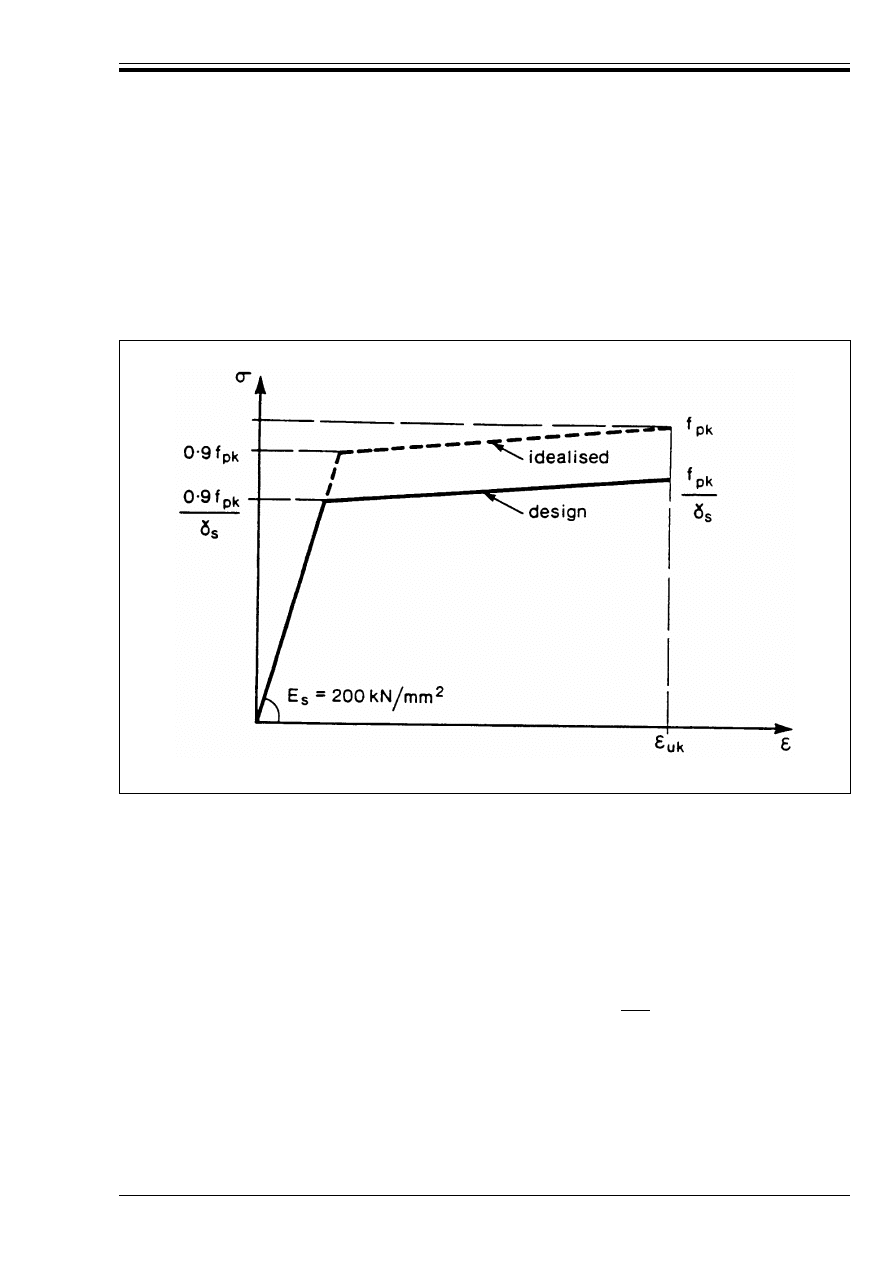
ENV 1992-1-1:1992
© BSI 12-1999
69
4.2.3.3.2 Modulus of elasticity
(1) The values given in 3.3.4.4 apply.
4.2.3.3.3 Stress-strain diagram
P(1) The general ductility requirements shall be in accordance with 3.3.4.3, and as specified in relevant
Standards.
(2) An idealized bi-linear diagram is given in Figure 4.6. This diagram is valid for temperatures
from – 20 °C to 200 °C.
(3) Figure 4.6 may generally be used for overall analysis, local verifications and the checking of section
capacity.
(4) Figure 4.6 may be modified, e.g. with a flatter or horizontal top branch, for local verifications or section
design.
(5) Design values for the steel stress are derived from the idealized characteristic diagram by dividing by
*
s
, the partial factor for prestressing steel (see 2.3.3).
(6) For section design, either of the following assumptions may be made:
— a horizontal top branch to the design curve in Figure 4.6, i.e. the stress in the prestressing steel is
limited to 0.9 f
pk
/*
s
with no limit to the steel strain, although in some cases it may be convenient to
assume a limit.
— an inclined top branch, with the increasing steel strain limited to |0.01|.
4.2.3.3.4 Ductility
(1) For structural analysis, if not stated otherwise, post-tensioned tendons may be assumed as having high
ductility: pre-tensioned tendons are assumed as having normal ductility.
4.2.3.3.5 Fatigue
(1) For fatigue requirements for prestressing steel, see Part 1E.
Figure 4.6 — Design stress-strain diagram for prestressing steel
Licensed copy:Heriot Watt University, 20/04/2004, Uncontrolled Copy, © BSI
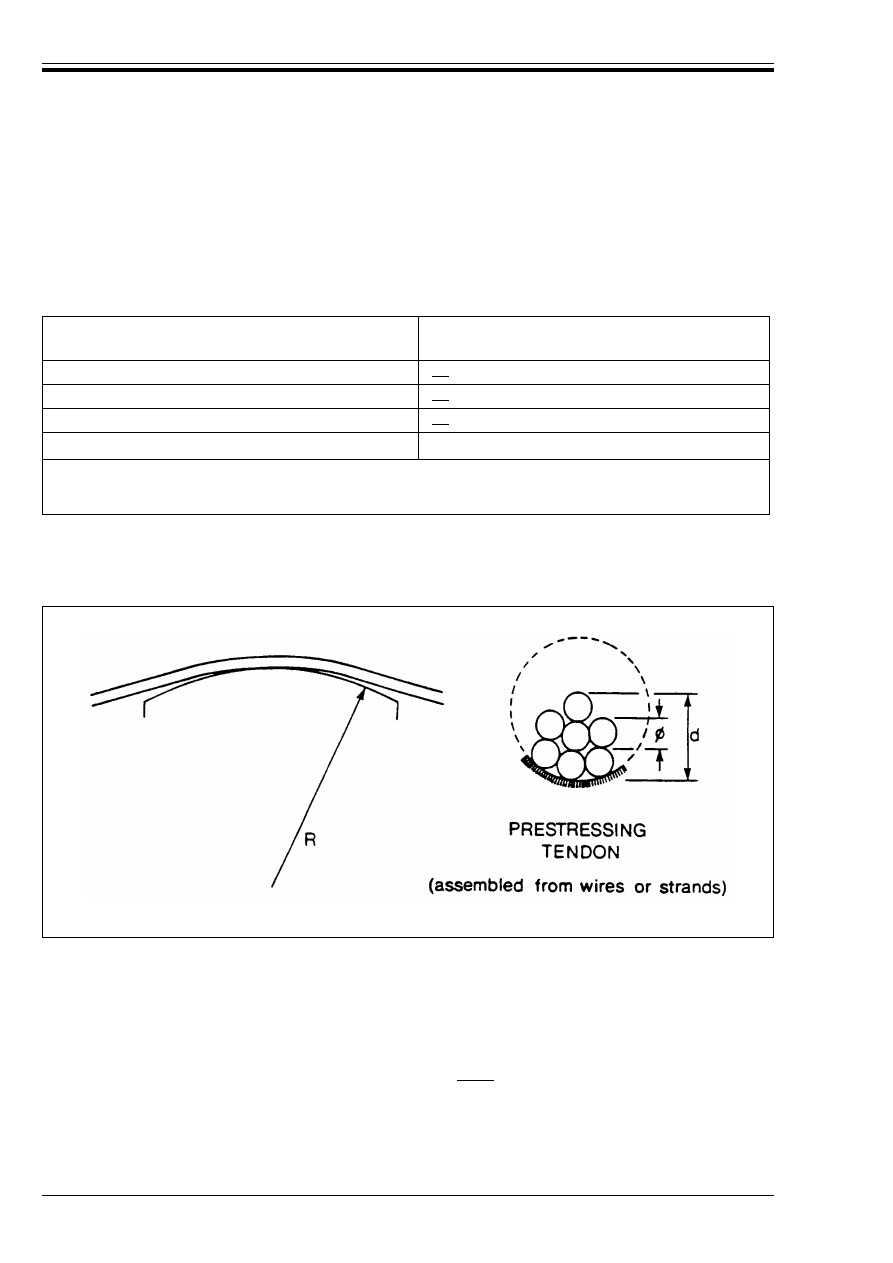
ENV 1992-1-1:1992
70
© BSI 12-1999
4.2.3.3.6 Multi-axial stresses
(1) If not stated otherwise in technical approval documents, tendons assembled from prestressing steel
satisfying the requirements of 3.3.4.6 may be considered to withstand the full specified tensile strength, if
the bending radius of the saddle, which is supporting the tendon at its point of deviation, satisfies the
requirements of Table 4.4.
(2) The values in Table 4.4 do not relate to the coefficients of friction in 4.2.3.5.5(8).
Table 4.4 — Criteria for satisfying multi-axial conditions in tendons
4.2.3.3.7 Anchorage or coupler assemblies of tendons
(1) Tendon anchorage assemblies and tendon coupler assemblies satisfying the performance requirements
of 3.4.1.2 may be considered to withstand the full characteristic strength of the tendon.
4.2.3.4
Technological properties of prestressing steel
4.2.3.4.1 Relaxation
P(1) Certificates accompanying the consignments shall indicate the class and relevant relaxation data of
the prestressing steel (see 3.3.5, and relevant Standards).
(2) For design calculations, the values which may be taken into account for losses at 1 000 h are either
those given in the certificate or those assumed in Figure 4.8 for the three classes of steel shown. The long
term values of the relaxation losses may be assumed to be |three| times the relaxation losses
after 1 000 h.
(3) An indication of how relaxation losses increase between 0–1 000 hours is given in Table 4.5.
Type of tendon
Single wire or strand, deflected after tensioning
|15|
Single wire or strand, tensioned in smooth duct
|20|
Single wire or strand, tensioned in ribbed duct
|40|
Multi wire or strand tendon
Preceding values multiplied by n
1
/n
2
in which: n
1
= total number of wires or strands in the tendon
n
2
= number of wires or strands transferring the radial force of all wires or strands in the tendon to the deviator.
(See Figure 4.7 below).
Figure 4.7 — Example of n
1
/n
2
value in Table 4.4 (in this case n
1
/n
2
= 7/3)
Ratio Minimum bending radius
Nominal diameter
-------------------------------------------------------------------------------
Licensed copy:Heriot Watt University, 20/04/2004, Uncontrolled Copy, © BSI
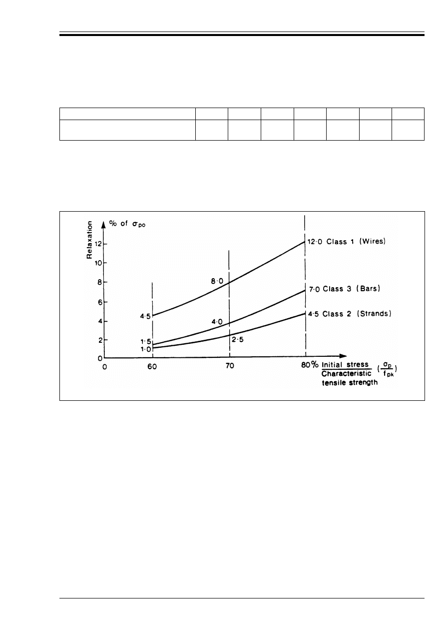
ENV 1992-1-1:1992
© BSI 12-1999
71
Table 4.5 — Indication of relationship between relaxation losses and time
up to 1 000 hours
(4) Relaxation at temperatures of the structure over 20 °C will be higher than given in Figure 4.8. This
may affect building structures in hot climates, power plants, etc. If necessary the producer should be
asked to include relevant information in the certificate [see 3.3.2(2)].
(5) Short-term relaxation losses at a temperature of the structure exceeding 60 °C can be 2 to 3 times
those at 20 °C. However, in general, heat curing, over a short period, may be considered to have no effect
on long term relaxation results (see 4.2.3.5.5).
4.2.3.4.2 Susceptibility to stress corrosion
(1) The provisions of 3.3.5.3 apply.
4.2.3.4.3 Temperature dependent behaviour
See separate Part on Fire Resistance.
4.2.3.5
Design of members in prestressed concrete
4.2.3.5.1 General
P(1) This section relates to structures where prestress is provided by fully bonded internal tendons.
P(2) The effects of prestressing to be considered include:
— minimum requirements for concrete classes (4.2.3.5.2)
— minimum requirements for prestressing units (4.2.3.5.3)
— determination of the relevant prestressing force (2.5.4)
— initial prestressing force (4.2.3.5.4)
— loss of prestress (4.2.3.5.5)
— transfer of prestressing forces and anchorage zone design for pre-tensioned members (4.2.3.5.6)
— anchorage zones in post-tensioned members (4.2.3.5.7)
(3) The provisions of 2.5.4 should be applied in all calculations relating to the effects of prestress both in
global and local analysis and in section design for the ultimate and serviceability limit states.
Time in hours
1
5
20
100
200
500
1 000
Relaxation losses as percentages of
losses after 1 000 hours
15
25
35
55
65
85
100
Figure 4.8 — Relaxation losses after 1 000 h at 20 °C
Licensed copy:Heriot Watt University, 20/04/2004, Uncontrolled Copy, © BSI
ENV 1992-1-1:1992
72
© BSI 12-1999
4.2.3.5.2 Minimum strength class for prestressed concrete
(1) The minimum class for post-tensioned members is |C25/30|, and for pre-tensioned members
is |C30/37|.
4.2.3.5.3 Minimum number of prestressing units in isolated structural elements
P(1) Isolated prestressed concrete members shall contain in the pre-compressed tensile zone a minimum
number of prestressing units in order to ensure that, with an adequate reliability, a failure of a certain
number of bars, wires or tendons does not lead to a failure of the member.
(2) P(1) above applies to structural prestressed members in which no additional load-carrying capacity
due to redistribution of internal forces and moments, transverse redistribution of loads or due to other
measures (e.g. normal steel reinforcement) exists.
(3) The requirement of P(1) above may be considered to be met if the minimum number of bars, wires or
tendons given in Table 4.6 is provided. Table 4.6 assumes equal diameters of all bars, wires or tendons.
(4) The requirement may also be assumed to be satisfied if at least one strand with seven or more wires
(wire diameter T 4.0 mm) is provided in the isolated member.
(5) If the actual number of bars, wires or tendons in the isolated member is less than the values given
in Table 4.6, adequate reliability against failure should be demonstrated.
Table 4.6 — Minimum number of bars, wires and tendons in the pre-compressed
tensile zone of isolated members
4.2.3.5.4 Initial prestressing force
P(1) The initial prestressing force shall be determined in accordance with 2.5.4, which also lists relevant
facto affecting loss of prestress.
P(2) The maximum force applied to a tendon P
o
(i.e. the force at the active end, immediately after
stressing, x = 0, see 2.5.4.2) shall not exceed A
p
. B
o,max
, where:
P(3) The prestressing force applied to the concrete immediately after tensioning (post-tensioning) or after
transfer (pre-tensioning), i.e. P
mo
= A
p
B
pmo
, shall not exceed the lesser of the forces determined from:
where B
pmo
is the stress in the tendon immediately after tensioning or transfer.
(4) For pre-tensioned members, P
m,o
, in P(3) above, is calculated from Equation (4.7) below:
(5) For post-tensioned members, P
m,o
is calculated from (4.8) below.
(6) Methods for evaluating %P
s1
, %P
c
, %P
ir
and %Pu(x) are given in 4.2.3.5.5.
Type of unit
Minimum number
Individual bars and wires
|3|
Bars and wires, forming a strand or a tendon
|7|
Tendons except strands (see para (4) above)
|3|
A
p
is the cross-sectional area of the tendon
and B
o,max
is the maximum stress applied to the tendon
B
o,max
= |0.80| f
pk
or = |0.90| f
p0.1k
,
whichever is the lesser
(4.5)
A
p
· B
pmo
= |0.75| f
pk
· A
p
, or |0.85| f
p
0.1 k · A
p
(4.6)
P
m,o
= P
o
– %P
c
– % P
ir
[– %Pu (x)]
(4.7)
where %P
c
, and %Pu(x) are defined in 2.5.4.2
and %P
ir
is the short-term relaxation loss.
P
m,o
= P
o
– %P
s1
– %P
c
– %Pu(x)
(4.8)
Licensed copy:Heriot Watt University, 20/04/2004, Uncontrolled Copy, © BSI

ENV 1992-1-1:1992
© BSI 12-1999
73
P(7) The minimum concrete strength required at the time of tensioning or stress transfer shall be indicated
in technical approval documents for the prestressing system concerned. Where such documents do not
exist, requirements concerning reliability and performance should be considered.
(8) The limiting values of P(2) and P(3) above are generally valid; they may be modified, however,
depending on a number of factors, e.g.:
— whether it is possible to replace a damaged tendon,
— the consequences of the fracture of a tendons, in particular, danger to human life.
— the stress levels in the concrete due to prestressing,
— the grade of steel and type of tendon used,
— whether or not the tendons are subsequently bonded,
— the time when the grout is injected into the ducts.
— the possibility of achieving the required prestressing force in
— the tendon by overstressing when unexpectedly high friction is met; in this exceptional case, the
maximum initial force P
o
may be increased to |0.95| f
p
0.1 k · A
p
.
4.2.3.5.5 Loss of prestress
P(1) Loss of prestress shall be calculated in accordance with the principles in 2.5.4.2.
(2) An estimate is required of the effective prestress at various stages considered in the design, and hence
an allowance has to be made for appropriate losses of prestress due to the different factors given
in 2.5.4.2. Whenever possible, these calculations should be based on experience or on experimental data
relating to the materials and prestressing methods to be used. For a wide range of structures, and in the
absence of such data, the general recommendations given in (5)–(11) may be used, in approximately
estimating the total loss of prestress.
(3) It is recommended that the actual values of prestressing losses at tensioning should be checked by
measuring the prestressing force transferred from one end of the tendon to the other.
(4) Immediate losses should be calculated in accordance with (5) to (8) below. Time dependent losses
should be calculated in accordance with (9)–(10) below.
(5) Loss of prestress due to anchorage slip (%P
s1
) should be determined from experience and technical
approval documents relating to the prestressing system to be used.
(6) Calculation of the immediate loss of force in the tendons due to elastic deformation of the concrete
(%P
c
) may be based on the values of the modulus of elasticity of the concrete given in 3.1.2.5.2 and on the
values for the prestressing steel given in 3.3.4.4.
For pre-tensioning, the loss of prestress should be calculated on a modular ratio basis, using the stress in
the adjacent concrete.
For post-tensioning, a progressive loss occurs when tendons are not stressed simultaneously. Where
greater accuracy is not required, this should be calculated on the basis of half the product of the modular
ratio and the stress in the adjacent concrete averaged along the length of the tendons.
(7) The short-term relaxation loss (%P
ir
), which occurs in pre-tensioning between stressing the tendons
and transferring the stress to the concrete, should be estimated using the data in 4.2.3.4.1.
(8) The loss of prestress in post-tensioned tendons due to friction [%Pu(x)] may be estimated from:
where:
u depends on the surface characteristics of the tendons and the duct, on the presence of rust, on the
elongation of the tendon and on the tendon profile. In the absence of more exact data, for tendons which
fill about 50 % of the duct, the following values for u may be assumed, when using equation (4.9).
% Pu(x) = P
o
(1 – e
–u(e+k.x)
)
(4.9)
u
is the coefficient of friction between the tendons and their ducts
e
is the sum of the angular displacements over a distance x (irrespective of direction or sign)
k
is an unintentional angular displacement (per unit length) related to the profile of the tendons.
cold drawn wire
0.17
strand
0.19
Licensed copy:Heriot Watt University, 20/04/2004, Uncontrolled Copy, © BSI
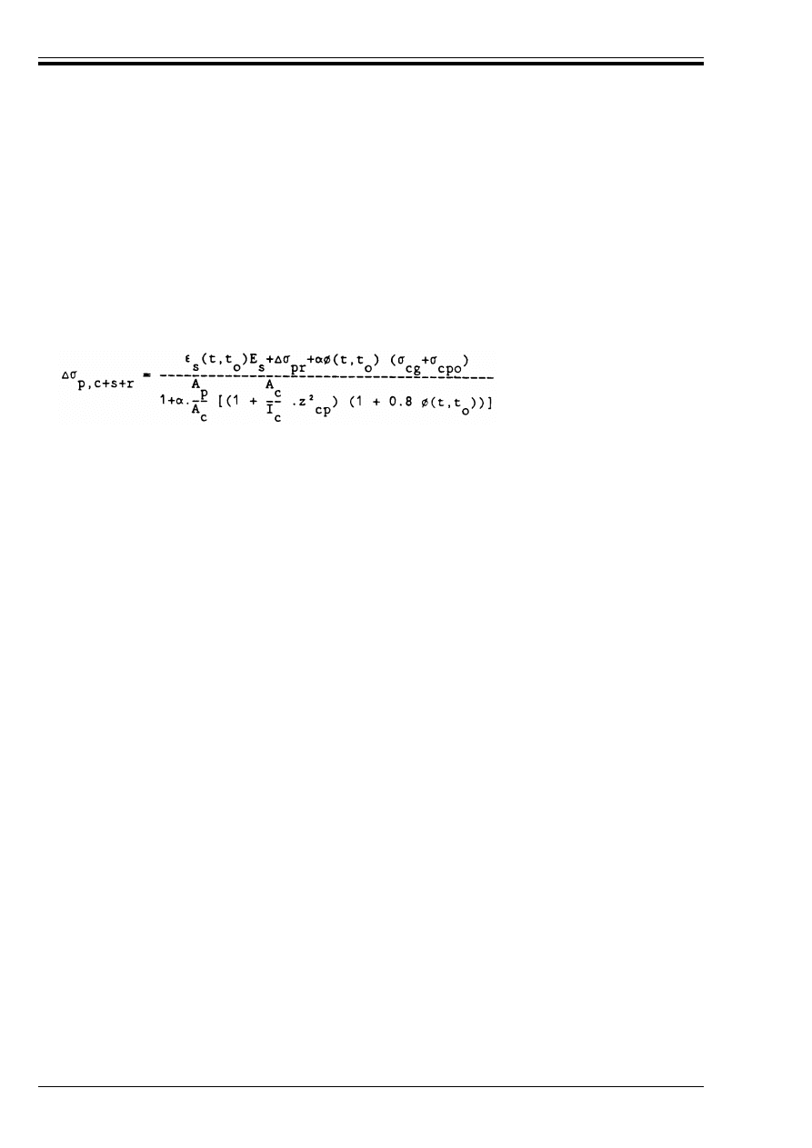
ENV 1992-1-1:1992
74
© BSI 12-1999
Values for k should be given in technical approval documents, and will generally be in the
range 0.005 < k < 0.01 per metre. The value depends on the quality of workmanship, on the distance
between tendon supports, on the type of duct or sheath employed, and on the degree of vibration used in
placing the concrete.
The above recommended values for u and k are mean values. The actual values used in design may be
increased or decreased, depending on standards of control, workmanship, special precautions, etc.,
provided that the selected values can be justified.
(9) Time dependent losses should be calculated from:
where:
In using Equation (4.10), an assumed value of total loss will be required initially, to permit the term %B
pr
on the right hand side to be evaluated (this term depends on the level of final prestress). An iterative
process is therefore necessary to solve and balance the two sides of Equation (4.10).
(10) The loss of prestress calculated in accordance with (9) above should be added to that determined
by (5)–(8) above to assess the final prestress (P
mZ
). It is important to remember that these procedures are
approximate, and may be adjusted to suit particular materials, stressing or design conditions.
(11) The design procedures to take account of the effects of prestress should be in accordance with 2.5.4.
deformed bar
0.65
smooth round bar
0.33
(4.10)
%B
p,c + s + r
r
is the variation of stress in the tendons due to creep, shrinkage and relaxation at
location x, at time t.
(
s
(t,t
o
)
is the estimated shrinkage strain, derived from the values in Table 3.4 for final
shrinkage (see also 2.5.5 and Appendix 1).
!
is E
s
/E
cm
E
s
is the modulus of elasticity for the prestressing steel, taken from 3.3.4.4.
E
cm
is the modulus of elasticity for the concrete (Table 3.2)
%B
pr
is the variation of stress in the tendons at section x due to relaxation. This may be
derived from Figure 4.8, for a ratio of initial stress/characteristic tensile stress, (B
p
/f
pk
)
calculated from:
B
p
= B
pgo
– 0.3 % B
p,c+s+r
(4.11)
where B
pgo
is the initial stress in the tendons due to prestress and permanent actions.
For simplification, and conservatively, the second term in equation (4.11) may be
ignored. For normal buildings, B
p
may be taken as 0.85 sB
pgo
.
Ì(t,t
o
)
is a creep coefficient, as defined in 2.5.5, (see also Appendix 1).
B
cg
is the stress in the concrete adjacent to the tendons, due to self-weight and any other
permanent actions
B
cpo
the initial stress in the concrete adjacent to the tendons, due to prestress
A
p
is the area of all the prestressing tendons at the level being considered.
A
c
is the area of the concrete section.
I
c
is the second moment of area of the concrete section.
z
cp
is the distance between the centre of gravity of the concrete section and the tendons
Licensed copy:Heriot Watt University, 20/04/2004, Uncontrolled Copy, © BSI
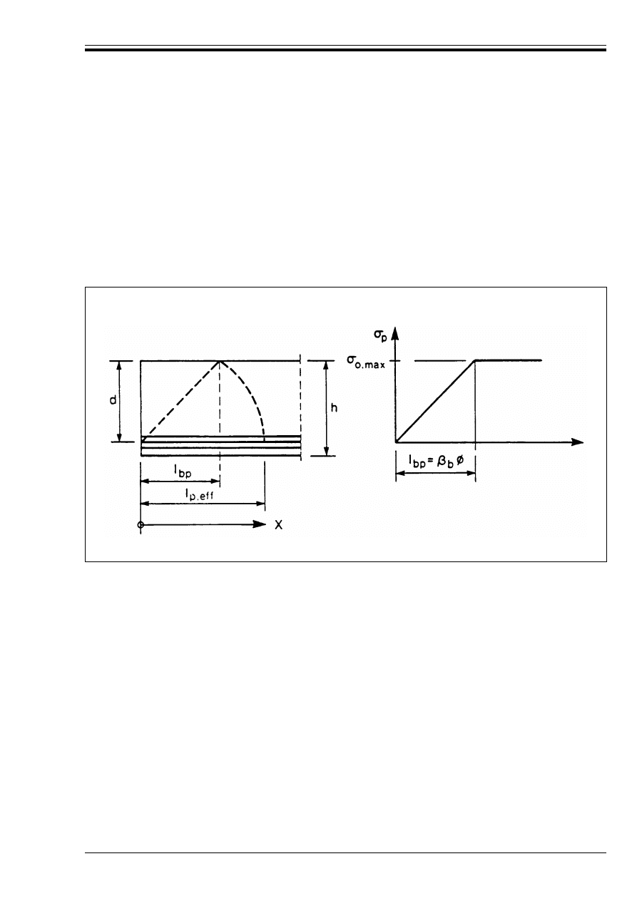
ENV 1992-1-1:1992
© BSI 12-1999
75
4.2.3.5.6 Anchorage zones of pretensioned members
(1) Where tensile forces can occur, they should be carried by additional reinforcement.
(2) A distinction has to be made (see Figure 4.9 a) between:
i) transmission length l
bp
, over which the prestressing force (P
o
) from a pretensioned tendon is fully
transmitted to the concrete.
ii) dispersion length l
p.eff
over which the concrete stresses gradually disperse to a linear distribution
across the concrete section.
iii) anchorage length l
ba
, over which the ultimate tendon force (F
pu
) in pretensioned members is fully
transmitted to the concrete (see 2.5.3.7.4).
The zones interact.
(3) The transmission length l
bp
is influenced by the size and type of tendon, the surface condition of the
tendon, the concrete strength, the degree of compaction of the concrete. Values should be based on
experimental data or experience with the type of tendon to be used. For design purposes, [Figure 4.9 b] the
transmission length is defined as a multiple of the nominal diameter (Ì) of the strand or wire:
For strands having a cross-sectional area r 100 mm
2
, and for indented wires with diameter r 8 mm, all
complying with surface characteristics specified in relevant Standards and tensioned according to the
values given in 4.2.3.5.4, the "
b
values given in Table 4.7 may be adopted. The concrete strength taken
should be that at the moment of transfer. Where the use of ribbed wires is proposed, with
diameter r 12 mm, values for "
b
should be based on test data; as a guide, the values in Table 4.7 may be
adopted.
a) definitions
b) design value of l
bp
Figure 4.9 (a) and (b) — Transfer of prestress in pretensioned elements
lb
p
= "
b
Ì
(4.12)
Licensed copy:Heriot Watt University, 20/04/2004, Uncontrolled Copy, © BSI
ENV 1992-1-1:1992
76
© BSI 12-1999
Table 4.7 — Factor "
b
to be taken for transmission length of prestressing
strands and wires (smooth or indented) in relation to concrete strength at
the moment of transfer
(4) The design value l
bpd
is to be taken at 0,8 l
bp
or 1,2 l
bp
whichever is less favourable for the effect
considered.
(5) Transmission length, anchorage length and dispersion length are to be taken from the start of effective
bond.
Start of effective bond should take account of:
— tendons purposely debonded, at the end
— a neutralised zone l
bp.o
in the case of sudden release
(6) For rectangular cross-sections and straight tendons, situated near the bottom of the section, the
dispersion length can be established as:
(7) The anchorage of pretensioning tendons in flexural members at the ultimate limit state is influenced by
the condition, cracked or uncracked, of the anchorage zone. The part of the beam where tendons are
anchored [Figure 4.9 a)] may be considered as uncracked if the concrete tensile stress at the ULS (flexural
and principal stresses) does not exceed f
ctd
, taking, account of the relevant value of P
d
(See 2.5.4).
(8) If the tensile stress does not exceed f
ct 0.05
, the conditions of anchorage may be assumed to be fulfilled
without further checks.
(9) If the tensile stress exceeds f
ct 0.05
, it should be shown that the envelope of the acting tensile force
according to Figure 5.11 does not exceed the resisting tensile force provided by the tendons and the
reinforcing steel within the anchorage zone. The ultimate resisting force F
px
of the tendons according
to Figure 4.9 c) may be determined as:
4.2.3.5.7 Anchorage zones of post-tensioned members
P(1) The design of anchorage zones shall be in accordance with the procedures in this section and those in
2.5.4, 4.2.3, 5.4.6 and 5.4.8.
P(2) When considering the effects of the prestress as a concentrated force on the anchorage zone, the
characteristic tensile strength of the tendon shall be used.
(3) The bearing stress behind anchorage plates should be calculated in accordance with 5.4.8.
(4) Tensile forces due to concentrated forces should be assessed by a strut and the tie model, or other
appropriate representation (see 2.5.3.6.3 and 2.5.3.7.4). The resulting reinforcement should be detailed in
accordance with 5.4.6, assuming that it is acting at its design strength.
(5) The prestressing force may be assumed to disperse at an angle of spread 2" (see Figure 4.10), starting
at the end of the anchorage device, where " may be assumed to be arc tangent 2/3.
Actual concrete strength at
transfer (N/mm
2
)
25
30
35
40
45
50
"
b
Strands and smooth
indented wires
75
70
65
60
55
50
Ribbed wires
|55|
|50|
|45|
|40|
|35|
|30|
(4.13)
(4.14)
P
o
l
bpd
as defined in 2.5.4.2 P(1)
as defined in (4) above.
Licensed copy:Heriot Watt University, 20/04/2004, Uncontrolled Copy, © BSI
ENV 1992-1-1:1992
© BSI 12-1999
77
Figure 4.9 c) — Derivation of Equation (4.14)
Figure 4.10 — Dispersion of prestress
Licensed copy:Heriot Watt University, 20/04/2004, Uncontrolled Copy, © BSI

ENV 1992-1-1:1992
78
© BSI 12-1999
4.3 Ultimate limit states
4.3.1 Ultimate limit states for bending and longitudinal force
4.3.1.0
Notation (See also 1.6 and 1.7)
4.3.1.1
General
P(1) This section applies to concrete beams or slabs which are either reinforced or prestressed with bonded
internal tendons.
P(2) The applied design forces and moments shall be determined in accordance with the principles stated
in Chapter 2.
P(3) Members shall be analysed at a sufficient number of cross-sections to ensure that the requirements of
the Code are satisfied at all cross-sections along the member.
P(4) The cross-section shall be chosen and the reinforcement detailed so that its design resistance,
determined in accordance with the assumptions set out in this section, is never less than that required to
resist all combinations of the design values of the effects of actions determined in accordance with the
provisions of Chapter 2.
(5) The effective width of T or L-beams should be assessed in accordance with 2.5.2.2.1. Where the flange
of such beams is in tension (such as a T-beam over an intermediate support), the tensile reinforcement,
required to provide the design flexural capacity, should be located in accordance with 5.4.2.1.2.
P(6) The contribution of prestressing tendons to the design resistance shall be assessed taking into
account the partial safety factors given in 2.3.3.1 Table 2.2 for the acting and resisting effects of prestress.
P(7) If the direction of the principal stress deviates significantly from that of the main reinforcement, this
shall be taken into account (See Appendix 2).
(8) For slabs, deviations between the direction of the principal stress and the main reinforcement of less
than 15° may be ignored.
For greater deviations, the moments should be transformed to give equivalent moments in the main
reinforcement directions.
4.3.1.2
Design resistance to bending and longitudinal force
P(1) In analysing a cross-section to determine its ultimate resistance, the assumptions given below shall
be used:
i) Plane sections remain plane.
ii) The strain in bonded reinforcement, whether in tension or compression, is the same as that in the
surrounding concrete.
iii) The tensile strength of the concrete is ignored.
iv) The stresses in the concrete in compression are derived from the design stress-strain curve in
either Figure 4.2 or Figure 4.3.
v) The stresses in the reinforcement or prestressing steel are derived from the design curves in
Figure 4.5 or Figure 4.6 respectively.
vi) The initial pre-strain in prestressing tendons is taken into account when assessing the stresses in the
tendons at the ultimate limit state (see 2.5.4.4.3).
vii) For cross-sections subject to pure longitudinal compression, the compressive strain in the concrete
is limited to – 0.002 (see Figure 4.2).
A
s1
Area of tension reinforcement effective at a section
A
s2
Area of reinforcement in the compression zone at the ultimate limit state
(
s1
Strain in tension reinforcement, for section analysis
(
s2
Strain in compression reinforcement, for section analysis
(
pm
Steel strain corresponding to P
m,t
(see 2.5.4.0)
%(
p
Variation of steel strain corresponding to %P
c
(see 2.5.4.0)
Licensed copy:Heriot Watt University, 20/04/2004, Uncontrolled Copy, © BSI
ENV 1992-1-1:1992
© BSI 12-1999
79
viii) For cross-sections not fully in compression, the limiting compressive strain is taken as – 0.0035. In
intermediate situations, the strain diagram is defined by assuming that the strain is – 0.002 at a
level 3/7 of the height of the section from the most compressed face.
(2) The adoption of the assumptions in P(1) above leads to the range of possible strain diagrams shown
in Figure 4.11.
(3) In some cases where the interaction of local strength and deformation are significant, it may be
convenient to assume a limiting tensile strain in the reinforcement and prestressing steel (see 4.2.2.3.2
and 4.2.3.3.3).
(4) As an alternative to the approach in P(1) above, the approach in 4.2.1.3.3(12) may be adopted.
(5) For prestressed members with permanently unbonded tendons, it is generally necessary to take the
deformation of the whole member into account (see Part 1D). However, for buildings where unbonded
tendons exist only during the construction phase, this is generally unnecessary.
(6) In the analysis of a cross-section which has to resist bending and only a small longitudinal force, the.
effect of the design ultimate longitudinal compressive force may be ignored if it does not exceed 0.08 f
ck
times the cross-sectional area.
(7) If changes in the position of the reinforcement, such as at a lap, can lead to a localised reduction in the
effective depth, the most unfavourable value should be used in the cross-section analysis.
4.3.1.3
Brittle failure and hyperstrength
P(1) Brittle failure of the cross-section at the formation of the first crack shall be avoided.
P(2) Flexural strengths in excess of those calculated on the basis of the assumptions given in this code shall
not be assumed for members with low percentages of high bond reinforcement even where testing shows
such strengths to be justified.
(3) The minimum steel percentages given by the provisions of 4.4.2 and in Chapter 5 should in most cases
be sufficient to ensure that brittle failure is avoided.
a) cross-section
b) strain distribution in the ultimate limit state
Figure 4.11 — Strain diagrams in the ultimate limit state
Licensed copy:Heriot Watt University, 20/04/2004, Uncontrolled Copy, © BSI

ENV 1992-1-1:1992
80
© BSI 12-1999
4.3.2 Shear
4.3.2.0
Notation (See also 1.6 and 1.7)
A
sf
Area of reinforcement across the flange of a flanged beam
A
sl
Area of tension reinforcement effective at a section
F
c
Compressive force in the concrete in the direction of the longitudinal axis
%F
d
Variation of the longitudinal force acting in a section of flange within the distance a
v
[See 4.3.2.5(3)]
F
s
Tensile force in longitudinal reinforcement
V
ccd
Force component in the compression zone, parallel to V
od
, of elements with variable depth
V
cd
Shear capacity of the concrete compression zone
V
od
Design shear force in the section, uncorrected for effects of variable section depth
V
pd
Force component due to inclined prestressing tendons
V
Rd1
Design shear resistance of a section in elements without shear reinforcement
V
Rd2
Maximum design shear force that can be carried without web failure
V
Rd2,red
Reduced value of V
Rd2,
due to axial force
V
Rd3
Design shear resistance of a section, in elements with shear reinforcement
V
td
Force component in the tensile zone, parallel to V
od
, in elements with variable depth
V
wd
Contribution of shear reinforcement
a
v
Distance between points of zero and maximum moment
b
w.nom
Nominal web thickness
f
ywd
Design yield strength of shear reinforcement
h
f
Flange depth
k
A constant relating to section depth and curtailment
s
f
Spacing of reinforcing bars across the flange of flanged beams
!
Angle of the shear reinforcement to the longitudinal axis of a member
"
Shear force enhancement coefficient
F
Angle of the concrete struts with the longitudinal axis of the member
*
Efficiency factor
@
1
Reinforcement ratio corresponding to A
sl
B
cp
Average stress in concrete due to axial force
B
cp.eff
Effective average stress in concrete due to axial force
Ù
Rd
Basic design shear strength of members without shear reinforcement
C Ì
Sum of diameter of prestressing ducts at a given level
Licensed copy:Heriot Watt University, 20/04/2004, Uncontrolled Copy, © BSI

ENV 1992-1-1:1992
© BSI 12-1999
81
4.3.2.1
General
P(1) This section applies to beams and slabs designed for flexure in accordance with 4.3.1. It also applies
to prestressed elements and columns subjected to significant shear forces designed in accordance with 4.3.1
and 4.3.5.
P(2) In general, a minimum amount of shear reinforcement shall be provided, even where calculation shows
that shear reinforcement is unnecessary. This minimum may be omitted in elements such as slabs, (solid,
ribbed, hollow), having adequate provision for the transverse distribution of loads, where these are not
subjected to significant tensile forces. Minimum shear reinforcement may also be omitted in members of
minor importance which do not contribute significantly to the overall strength and stability of the
structure.
(3) Rules for minimum shear reinforcement are given in 5.4. An example of a member of minor importance
would be a lintel of less than 2 m span.
P(4) In structures of variable depth, the design shear forces shall be modified by a contribution
corresponding to the components of the compressive and tensile resultants perpendicular to the member
axis.
P(5) In prestressed structures, in the calculation of V
Sd
account shall be taken of the effect of inclined
prestressing tendons.
P(6) When determining the necessary longitudinal reinforcement in areas subjected to shear, account shall
be taken of the possible increase of the tensile force beyond the value corresponding to the bending moment.
(7) This increase is covered by the “shift” rules given in Section 5.4.2.1.
4.3.2.2
Design method for shear
(1) The method for shear design, set out in the following sections, is based on three values of design shear
resistance:
(2) Any section for which the design shear, V
Sd
, is less than V
Rd1
, requires no design shear reinforcement
but except in the cases defined in 4.3.2.1 P(2) and (3), minimum shear reinforcement should be provided in
accordance with 5.4.
(3) For sections where V
Sd
exceeds V
Rd1
, shear reinforcement should be provided such that:
V
Sd
r V
Rd3
The amount of shear reinforcement should not be less than the minimum given in 5.4.2.2.
(4) In the absence of more rigorous analysis, at no section in any element should the design shear force
exceed V
Rd2
. (See 4.3.2.3). Where the member is subjected to an applied axial compression, V
Rd2
should be
reduced in accordance with Equation (4.15) below.
— V
Rd1 ·
the design shear resistance of the member without shear reinforcement. (See 4.3.2.3).
— V
Rd2 ·
the maximum design shear force that can be carried without crushing of the notional concrete
compressive struts. (See 4.3.2.3, 4.3.2.4.3, 4.3.2.4.4).
— V
Rd3 ·
the design shear force that can be carried by a member with shear reinforcement.
(See 4.3.2.4.3, 4.3.2.4.4).
V
Rd2.red
= 1.67 V
Rd2
(1 – B
cp.eff
/f
cd
) r V
Rd2
(4.15)
where:
V
Rd2.red
is the reduced value of V
Rd2
B
cp.eff
is the effective average stress in the concrete due to axial force. B
cp.eff
is given by
Equation (4.16) below
B
cp.eff
= (N
Sd
– f
yk
A
s2
/*
s
)/A
c
(4.16)
where:
N
Sd
is the design axial force
A
s2
is the area of reinforcement in the compression zone at the ultimate limit state
Licensed copy:Heriot Watt University, 20/04/2004, Uncontrolled Copy, © BSI

ENV 1992-1-1:1992
82
© BSI 12-1999
(5) Close to supports where the configuration of concentrated loads and support reaction is such that a
proportion of the loads may be carried to the support by direct compression (direct support), an allowance
may be made for an enhancement of the shear resistance V
Rd1
[see (9) below]. Any such enhancement of
V
Rd1
should be ignored when checking V
Rd2
.
(6) The attainment of V
Rd1
depends significantly on the proper anchorage of the tension reinforcement or
prestressing tendons on each side of any possible plane of failure. Rules are provided to ensure this, in
Chapter 5.
(7) For cases where V
Sd
> V
Rd1
, two design methods are given in the following clauses:
— the standard method (4.3.2.4.3) and
— the variables truss angle method (4.3.2.4.4).
The variable truss angle method allows more freedom in the arrangement of reinforcement than the
standard method. It will frequently lead to substantial economies in shear reinforcement but may require
increases in the longitudinal tension steel.
It should be used when a member is subjected to combined shear and torsion.
(8) If the web contains grouted ducts with a diameter Ì > b
w
/8 the shear resistance V
Rd2
should be
calculated on the basis of a nominal web thickness given by:
b
w,nom
= b
w
– 1/2 CÌ
where C Ì is determined for the most unfavourable level.
(9) For members without shear reinforcement, and for members with shear reinforcement where the
Standard Method of shear design is used (4.3.2.4.3) and where the conditions set out in (11) below are
satisfied, an enhancement of shear resistance, only for concentrated loads situated at a distance x r 2.5 d
from the face of the support, is permitted [(5) above]. Solely for this purpose, the value Ù
Rd
in
Equation (4.18) may be multiplied by a factor ", when estimating V
Rd1
, where:
When this enhancement is taken into account, V
Rd1
and shear reinforcement should be calculated at all
critical sections over the length 2.5 d from the face of the support, with " = 1.0 on the span side of the
relevant concentrated loads; the maximum shear reinforcement so obtained should be provided over this
entire length.
Where the dominant load on a beam is a concentrated load close to a support, the above procedure may lead
to minimum reinforcement throughout the beam. In these cases, care is required, and the designer may
wish to base the resistance on the unenhanced V
Rd1
.
(10) Because of the increased resistance due to direct transmission of loads close to supports, it will
normally be conservative to evaluate V
Sd
at a distance d from the face of a direct support on beams or slabs
with continuously distributed loading.
(11) When taking account of the increased shear strength close to the supports in (9) or (10) above, the
following conditions should be satisfied.
a) the loading and support reactions are such that they cause diagonal compression in the element
(direct support).
b) at an end support, the whole tension reinforcement required within a distance of 2.5 d from the
support should be anchored into the support.
c) at an intermediate support the tension reinforcement required at the face of the support should
continue for at least 2.5 d + 1
b.net
into the span.
f
yk
is the yield strength of the compression steel.
(f
yk
/*
s
should not exceed 400 N/mm
2
)
A
c
is the total area of the concrete cross-section.
" = 2.5d/x, with 1.0
r " r |5.0|
(4.17)
Licensed copy:Heriot Watt University, 20/04/2004, Uncontrolled Copy, © BSI
ENV 1992-1-1:1992
© BSI 12-1999
83
4.3.2.3
Elements not requiring design shear reinforcement (V
Sd
r V
Rd1
)
(1) The design shear resistance V
Rd1
is given by:
Table 4.8 — Values for Ù
Rd
(N/mm
2
) with *
c
= 1.5 for different concrete strengths
(2) Equation (4.18) only applies to the anchorage zones of pretensioned members where the anchorage
requirements of 4.2.3.5.6 are satisfied.
(3) When checking sections without designed shear reinforcement, the design resistance V
Rd2
is given by:
(4.18)
where
Ù
Rd
= basic design shear strength = (0.25 f
ctk0.05
)/*
c
. *
c
should be taken as |1.5|. Values of Ù
Rd
are
given in Table 4.8.
k = |1| for members where more than 50 % of the bottom reinforcement is curtailed.
otherwise,
k = |1.6 – d “ 1| (d in metres)
A
s1
= the area of tension reinforcement extending not less than d + l
b.net
beyond the section
considered (see Figure 4.12). l
b.net
is defined in 5.2.2.3, and Figure 5.2.
b
w
= minimum width of the section over the effective depth.
B
sp
= N
Sd
/A
c
N
Sd
= longitudinal force in section due to loading or prestressing (compression positive).
f
ck
12
16
20
25
30
35
40
45
50
Ù
Rd
0.18
0.22
0.26
0.30
0.34
0.37
0.41
0.44
0.48
Figure 4.12 — Definition of A
sl
for use in Equation (4.18)
(4.19)
where
(f
ck
in N/mm
2
)
(4.20)
Licensed copy:Heriot Watt University, 20/04/2004, Uncontrolled Copy, © BSI
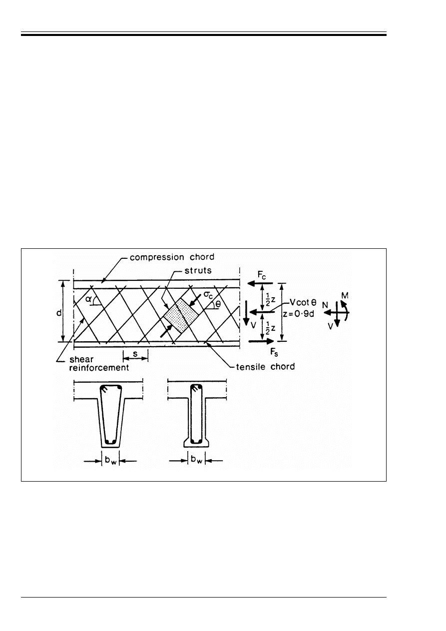
ENV 1992-1-1:1992
84
© BSI 12-1999
4.3.2.4
Elements requiring design shear reinforcement (V
Sd
> V
Rd1
)
4.3.2.4.1 General
P(1) In beams, bent-up bars shall not be used as shear reinforcement except in combination with stirrups.
At least 50 % of V
Sd
shall be resisted by vertical stirrups.
P(2) Where inclined shear reinforcement is used, the angle between the reinforcement and the longitudinal
axis of the beam should not be less than 45°.
P(3) Where the load is not acting at the top of the beam, or when the support is not at the bottom of the
beam suspension reinforcement should be provided to transfer the load to the top of the design truss
system.
4.3.2.4.2 Members with constant depth
P(1) For shear design, the member is assumed to consist of compressive and tensile zones separated by a
distance equal to the internal lever arm z. The shear zone has a depth equal to z and width b
w
. The
internal lever arm is calculated perpendicular to the longitudinal reinforcement by ignoring the effect of
any bent-up longitudinal reinforcement.
(2) The notation used is given in Figure 4.13.
The parameters given in Figure 4.13 are:
Figure 4.13 — Notation for members subjected to shear
!
— the angle of the shear reinforcement with the longitudinal axis.
F
— the angle of the concrete struts with the longitudinal axis.
F
s
— tensile force in the longitudinal reinforcement.
F
c
— the compression force in the concrete in the direction of the longitudinal axis.
b
w
— minimum width of the web.
z
— denotes, for a member with constant depth, the internal lever arm corresponding to the
maximum bending moment in the element under consideration. In the shear analysis, the
approximate value z = 0.9 d can normally be used. In elements with inclined prestressing
tendons, longitudinal reinforcement at the tensile chord should be provided to carry the
longitudinal tensile force due to shear defined by Equation (4.30).
Licensed copy:Heriot Watt University, 20/04/2004, Uncontrolled Copy, © BSI
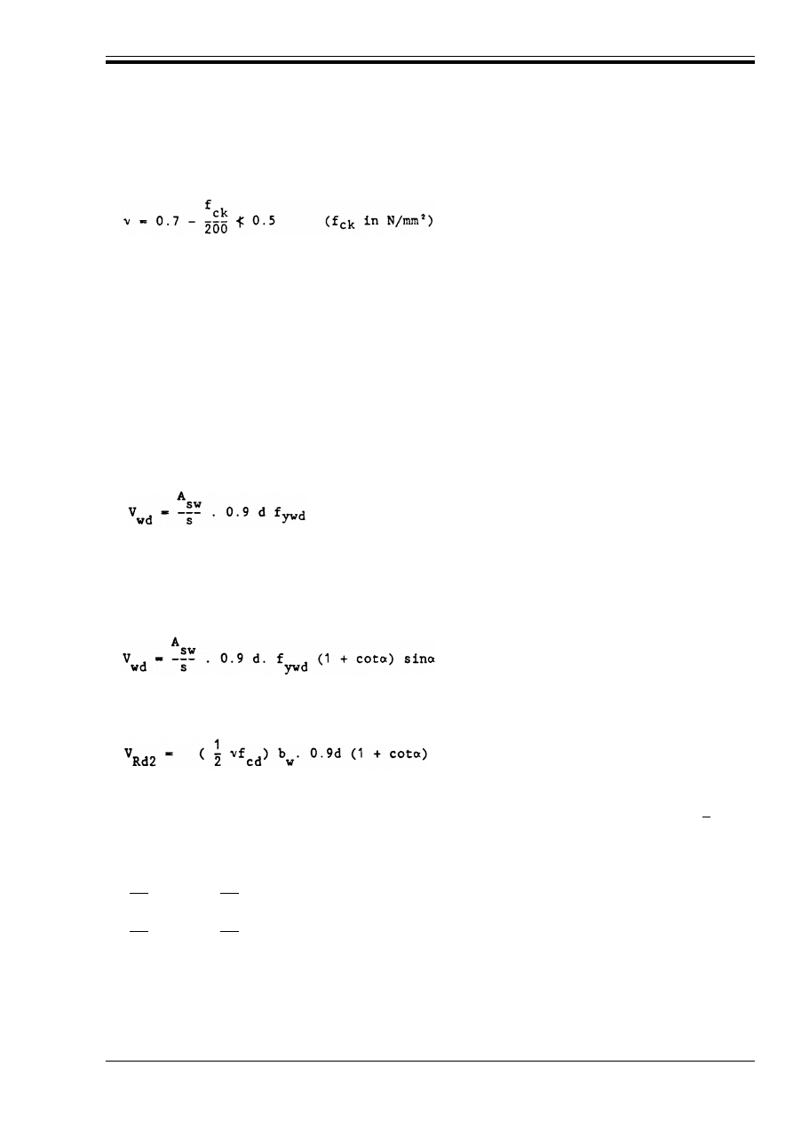
ENV 1992-1-1:1992
© BSI 12-1999
85
(3) The concrete stress in the struts should be limited to B
c
r 5f
cd
where 5 is the effectiveness factor given
by:
(4) The following detailing rules apply to the provision of shear reinforcement:
— the minimum percentage of shear reinforcement in 5.4.2.2.
— the limitation of the crack widths in the web in 4.4.2.
— the detailing arrangements for shear reinforcement in 5.4.2.
4.3.2.4.3 Standard method
(1) The shear resistance of a section with shear reinforcement is given by the equation:
(2) The contribution of vertical shear reinforcement is given by the equation:
(3) The contribution of inclined shear reinforcement is given by the equation:
(4) When checking against crushing at the compression struts, V
Rd2
is given by the equation:
(5) The forces in the tension chords of beams may be obtained from Equation (4.30) with cot F = |1|
4.3.2.4.4 Variable strut inclination method
(1) The notation used is given in Figure 4.13. The angle of the concrete struts F with the longitudinal axis
is limited to:
|0.4| < cotF < |2.5|
for beams with constant longitudinal reinforcement; and to
|0.5| < cotF < |2.0|
for beams with curtailed longitudinal reinforcement. Other limiting values of F may be used provided they
can be justified.
(4.21)
V
Rd3
= V
cd
+ V
wd
(4.22)
V
cd
is the contribution of the concrete and is equal to V
Rd1
, calculated in accordance with 4.3.2.3 or
as enhanced in 4.3.2.2(9).
V
wd
is the contribution of the shear reinforcement.
(4.23)
where A
sw
is the cross-sectional area of the shear reinforcement.
s is the spacing of the stirrups.
f
ywd
is the design yield strength of the shear reinforcement.
(4.24)
s is the spacing measured along the longitudinal axis, (see Figure 4.13).
(4.25)
For vertical stirrups, or for vertical stirrups combined with bent-up bars, cot! is taken as zero.
Licensed copy:Heriot Watt University, 20/04/2004, Uncontrolled Copy, © BSI
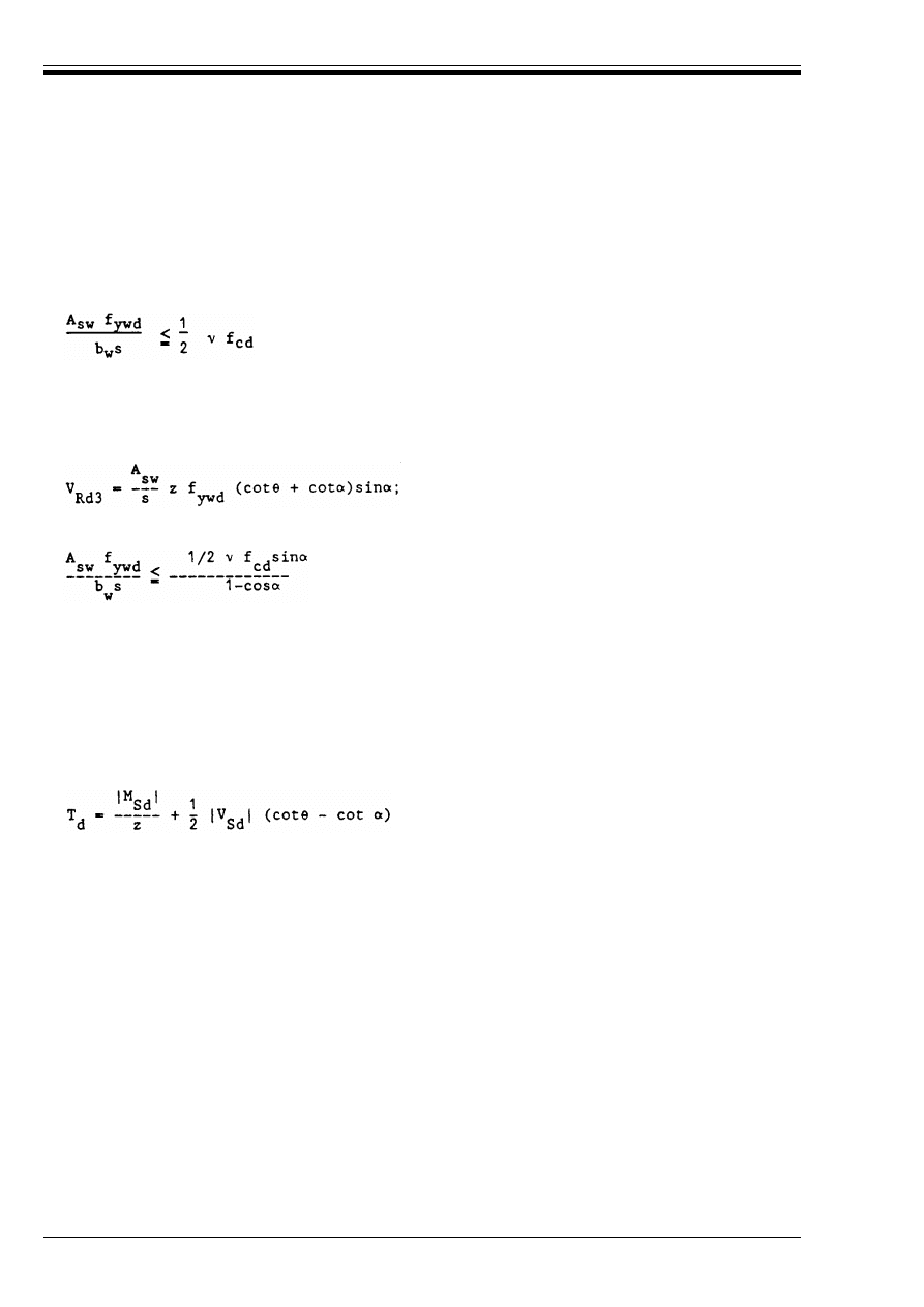
ENV 1992-1-1:1992
86
© BSI 12-1999
(2) For elements with vertical shear reinforcement, the shear resistances are defined by:
The effectiveness factor 5 is given by Equation (4.21). The lever arm, z, may normally be taken as 0.9 d.
(3) For elements with inclined shear reinforcement, the shear resistances are defined by:
(4) To find the least amount of shear reinforcement, for low and intermediate shear stresses, the upper
limits given in (1) above for cot F will normally govern the design. For higher shear stresses, the largest
value of cot F (corresponding to the lowest amount of shear reinforcement) may be found by equating the
design shear force V
Sd
to V
Rd2
. The amount of shear reinforcement is then found by equating the design
shear force V
Sd
to V
Rd3
. The value of cot F may alternately be selected to optimise the design, for example
by minimising the total amount of reinforcement.
(5) The tensile force in the longitudinal reinforcement can be calculated from:
(6) As an alternative to Equation (4.30), the T
d
-curve may be constructed by displacing the M
Sd
/z-curve a
distance (cotF – cots!) z/2, z 0.9d (cotF – cot!)/2, in such a direction that M
Sd
/z is always increased (“shift”
rule, see 5.4.2).
(7) At indirect supports the longitudinal reinforcement should always resist the tensile force T
d
, defined by
Equation (4.30).
(8) The second term of Equation (4.30) gives the increase of the tensile force above the value determined by
taking account of only the bending moment.
4.3.2.4.5 Elements of variable depth
(1) Taking into account the variation in the internal lever arm, the design shear force is given by:
V
Rd2
= b
w
z 5 f
cd
/(cotF + tanF)
(4.26)
;
(4.27)
however, with
V
Rd2
= b
w
z 5 f
cd
(cotF + cot!)/(1 + cot
2
F)
(4.28)
(4.29)
however, with
z may normally be taken as 0.9 d.
(4.30)
where z = 0.9 d.
V
Sd
= V
od
– V
ccd
– V
td
(4.31)
where
V
od
is the design shear force in the section
V
ccd
the force component in the compression zone, parallel to V
od
.
V
td
the force component in the tensile zone, parallel to V
od
.
V
ccd
and V
td
are taken as positive in the same direction as V
od
.
V
Rd3
A
sw
s
-----------
z
f
ywd
cotF
=
Licensed copy:Heriot Watt University, 20/04/2004, Uncontrolled Copy, © BSI
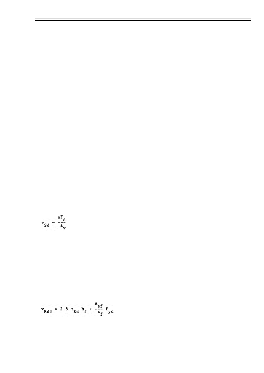
ENV 1992-1-1:1992
© BSI 12-1999
87
(2) A reduction of V
od
determined by Equation (4.31) Can only be combined with a reduction according
to 4.3.2.4.6 if a detailed verification can be given.
4.3.2.4.6 Members with inclined prestressing tendons
(1) Taking into account the effect of inclined prestressing tendons, the design shear force is given by:
(2) Concerning the value V
pd
in Equation (4.32), two cases should be distinguished:
(3) 4.3.2.4.5(2) applies.
(4) In shear analysis, the effective depth d is calculated ignoring the inclined tendons.
4.3.2.5
Shear between web and flanges
P(1) The shear strength of the flange may be calculated considering the flange as a system of compressive
struts combined with ties in the form of tensile reinforcement.
P(2) The ultimate limit state may be attained by compression in the struts or by tension in the ties which
ensure the connection between flange and web. At least a minimum amount of reinforcement shall be
provided, see Chapter 5.
(3) The mean longitudinal sliding shear per unit length to be resisted is defined by:
where
%F
d
is the variation of the longitudinal force acting in a section of flange within the distance a
v
.
See Figure 4.14.
a
v
is the distance between points of zero and maximum moments (see Figure 4.14)
(4) In the absence of more rigorous calculations, it should be checked that:
V
Sd
= V
od
– V
pd
(4.32)
where
V
pd
denotes the force component of the inclined prestressed tendons, parallel to V
od
.
V
pd
is taken as positive in the same direction as V
od
.
Case 1 : The stresses in the tendons do not exceed the characteristic strength f
p
0.1 k:
The relevant prestressing force is the mean value P
mt
allowing for losses [see 2.5.4.2 P(1)]
multiplied by the relevant safety coefficient (generally *
p
= 0.9).
Case 2 : The steel stress in the tendons exceeds f
p
0.1 k:
The prestressing force is calculated with f
p
0.1 k/*
s
.
(4.33)
v
Sd
r v
Rd2
(4.34)
v
Sd
r v
Rd3
(4.35)
with
v
Rd2
= 0.2 f
cd
h
f
(4.36)
(4.37)
Ù
Rd
is taken from Table 4.8 in 4.3.2.3. For A
sf
and s
f
, see Figure 4.14 above.
Licensed copy:Heriot Watt University, 20/04/2004, Uncontrolled Copy, © BSI

ENV 1992-1-1:1992
88
© BSI 12-1999
(5) If, at the section with M = M
max
, the flange is subjected to a tensile force, the concrete term 2.5 Ù
Rd
h
f
in Equation (4.37) should be neglected.
(6) In the case of combined shear, between the flange and web, and transverse bending, the greater of the
areas of steel required to satisfy either Equation (4.37) or transverse bending should be provided.
4.3.3 Torsion
4.3.3.0
Notation (See also 1.6 and 1.7)
4.3.3.1
Pure torsion
P(1) Where the static equilibrium of a structure depends upon the torsional resistance of elements of the
structure a full design for torsion covering both ultimate and serviceability limit states, will be necessary.
Where, in indeterminate structures, torsions arise from consideration of compatibility only, and the
structure is not dependent on torsional resistance for its stability, then it will commonly be unnecessary to
consider torsion at the ultimate limit state.
Figure 4.14 — Notation for the connection between flange and web
A
k
Area enclosed within the centre-line of a thin-walled cross-section (including inner hollow
areas)
A
s1
Required additional area of longitudinal reinforcement for torsion
T
Rd1
Maximum torsional moment resisted by compressive struts
T
Rd2
Maximum torsional moment resisted by reinforcement
V
Rd1
Design shear resistance of a section in elements without shear reinforcement
V
Rd2
Maximum design shear force that can be carried without web crushing
t
Thickness of wall
u
Outer circumference of a section having an area A
u
k
Circumference of area A
k
F
Angle between concrete struts and the longitudinal axis of the beam
5
Efficiency factor
Ù
Sd
Tangential shear stress due to torsion
Licensed copy:Heriot Watt University, 20/04/2004, Uncontrolled Copy, © BSI
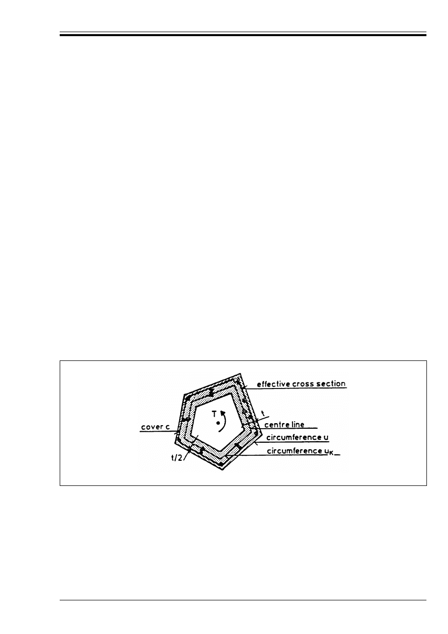
ENV 1992-1-1:1992
© BSI 12-1999
89
In cases where torsion is not essential for stability, torsion arising from some arrangements of structural
elements may need consideration to limit excessive cracking in the serviceability limit state.
(2) In cases where torsion does not require consideration at the ultimate limit state, a minimum
reinforcement in the form of stirrups and longitudinal bars should be provided to avoid excessive cracking.
The requirements of 4.4.2, 5.4.2.2 and 5.4.2.3 will normally be sufficient for this purpose.
(3) The torsional resistance of sections is calculated on the basis of a thin-walled closed section. Solid
sections are replaced by an equivalent thin-walled section. Sections of complex shape, such as “T” sections,
are divided into a series of sub-sections each of which is modelled as an equivalent thin-walled section and
the total torsional resistance taken as the sum of the capacities of the individual elements. The torsional
resistance moment carried by each individual sub-section should not deviate too far from that predicted
on the basis of an uncracked elastic calculation. For non-solid sections, the equivalent wall thickness
should not exceed the actual wall thickness. The torsional moment carried by the individual elements
according to elastic theory may be found on the basis of the St. Venant torsional stiffness. The St. Venant
torsional stiffness of a non-rectangular section may be obtained by dividing the section into a series of
rectangles and summing the torsional stiffness of these rectangles. The division of the section should be
arranged so as to maximize the calculated stiffness.
P(4) Reinforcement for torsion shall consist of closed stirrups combined with longitudinal bars distributed
around the periphery of the section. Longitudinal bars shall always be provided at all corners of the section
(See 5.4.2.3).
(5) The design torsional moment should satisfy the following two conditions:
(6) The resisting torsional moment T
Rd1
is given by:
T
Sd
r T
Rd1
(4.38)
T
Sd
r T
Rd2
(4.39)
where
T
Rd1
is the maximum torsional moment that can be resisted by the compressive struts in the
concrete.
T
Rd2
is the maximum torsional moment that can be resisted by the reinforcement.
Figure 4.15 — Notation used in Section 4.3.3.1
T
Rd1
= 2 5f
cd
t A
k
/(cotF + tanF)
(4.40)
where
t r A/u 8 the actual wall thickness. In the case of a solid section, t denotes the equivalent
thickness of the wall. A thickness less than A/u can be used provided T
Sd
r T
Rd1
, where T
Rd1
is
determined from Equation (4.40). A thickness less k than twice the cover, c, to longitudinal
bars is not allowed.
u = outer circumference
Licensed copy:Heriot Watt University, 20/04/2004, Uncontrolled Copy, © BSI
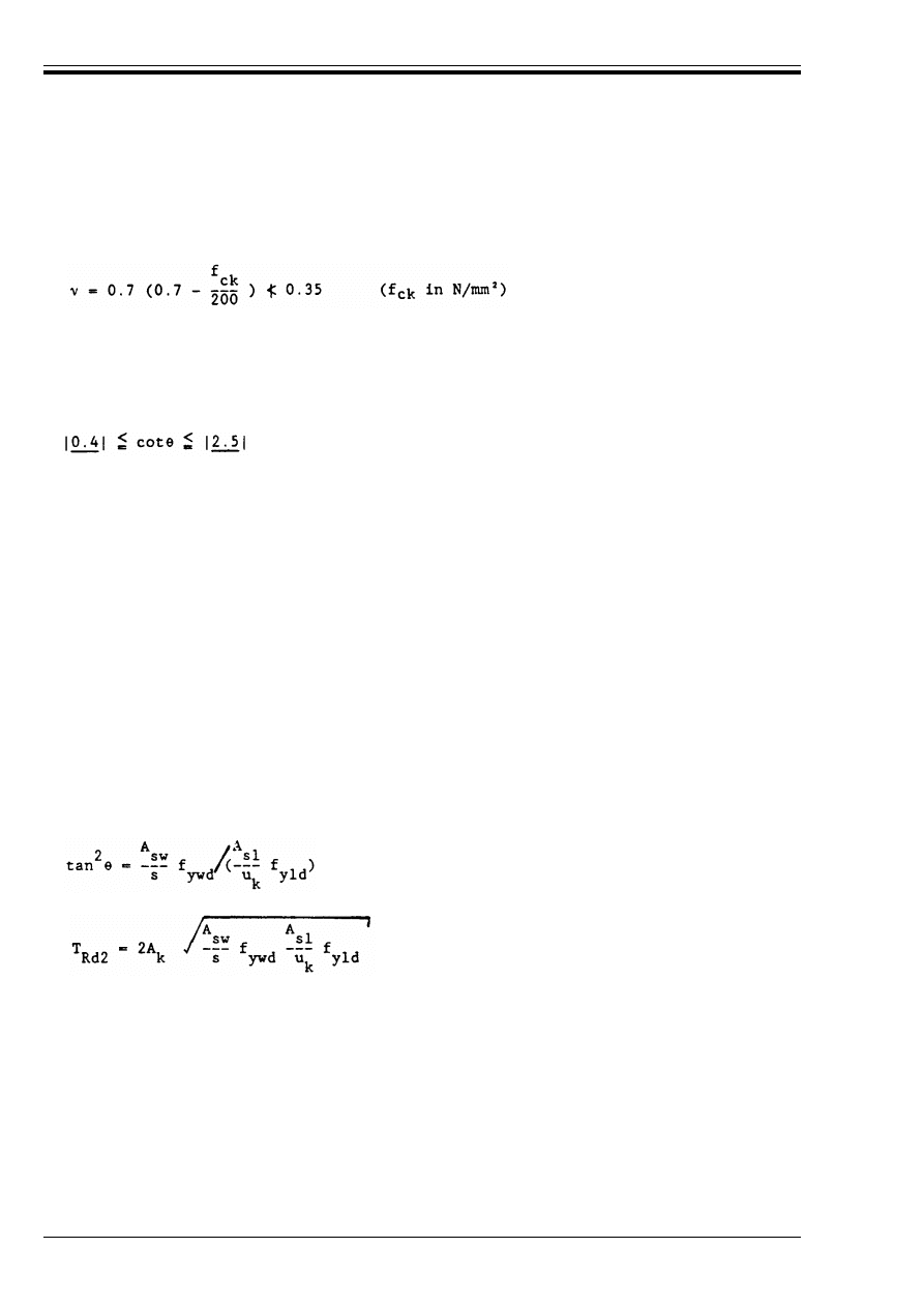
ENV 1992-1-1:1992
90
© BSI 12-1999
This value applies if there are stirrups only along the outer periphery of the member. If closed stirrups are
provided in both sides of each wall of the equivalent hollow section or in each wall of a box section, 5 can
be assumed to be 0.7 – f
ck
/200 @ 0.5.
F = the angle between the concrete struts and the longitudinal axis of the beam and should be chosen so
that:
Other values of F may be used provided they can be justified.
(7) The resisting torsional moment T
Rd2
is given by:
where
When the reinforcement is known, F and T
Rd2
may be determined from Equations (4.44) and (4.45) below.
If the resulting value of F lies outside the limits given by (4.42) the nearest limit should be taken.
(8) The resultant of the tensile forces F
s1
= A
s1
· f
yld
is assumed to act at the centre of gravity of the
equivalent hollow section; a portion of the longitudinal steel (or the prestressing tendons) may therefore
be placed along the centre line of the member; however, in order to ensure that the outward pressure
exerted by the struts is transmitted to the stirrups, it is necessary for at least one longitudinal bar to be
located at each corner of the actual section.
(9) For pure torsion, the following detailing requirements apply:
— the minimum percentage of reinforcement in 5.4.2.2
— the limitation of the crack widths in 4.4.2
— the detailing arrangement of reinforcement in 5.4.2.3
A = the total area of the cross-section within the outer circumference, including inner hollow areas.
A
k
= the area enclosed within the centre-line of the thin-walled cross-section, including inner hollow
areas.
(4.41)
(4.42)
T
Rd2
= 2A
k
(f
ywd
· A
sw
/s) cotF
(4.43)
and the additional area of longitudinal steel for torsion is given by:
A
sl
· f
yld
= (T
Rd2
· u
k
/2A
k
) · cot F
(4.44)
u
k
= the circumference of the area A
k
s
= the spacing of the stirrups
f
ywd
= the design yield strength of stirrups
f
yld
= the design yield strength of longitudinal reinforcement A
sl
A
sw
= the cross-sectional area of the bars used as stirrups
A
sl
= the required additional area of the longitudinal steel for torsion
(4.45)
(4.46)
Licensed copy:Heriot Watt University, 20/04/2004, Uncontrolled Copy, © BSI
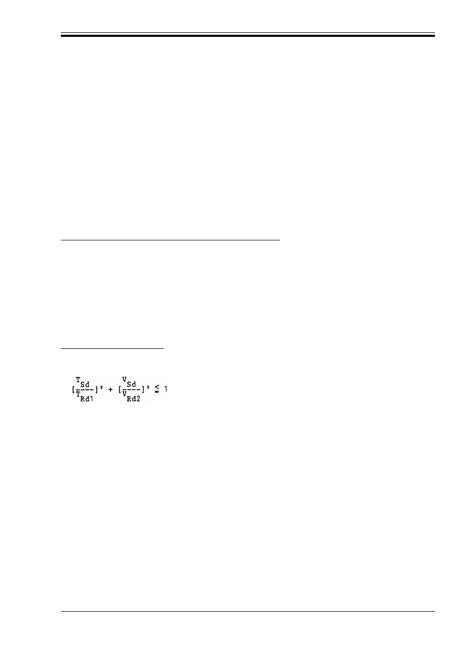
ENV 1992-1-1:1992
© BSI 12-1999
91
4.3.3.2
Combined effects of actions
4.3.3.2.1 General procedure
(1) The same procedure is used to define an equivalent thin walled closed section as for pure torsion. The
normal and shear stresses in this section are determined by conventional elastic or plastic methods
(2) When the stresses have been found, the necessary reinforcement at any point of the thin-walled section
can be determined by plane stress distribution formulae. The concrete stress can also be determined. If the
reinforcement so found is not feasible in practice, it may be changed to another statically equivalent
reinforcement lay-out, provided that the effects of this change are taken into account in regions near beam
ends and holes (See A2.8).
(3) The concrete stress resulting from combined shear and torsion in the individual walls of the equivalent
thin-walled section should not exceed B
c
= 5f
cd
where 5 is given by Equation (4.41) in 4.3.3.1.
(4) For box sections with reinforcement in both faces of each wall, 5 may be taken as 0.7 – f
ck
/200 @ 0.5 for
walls subjected to shear stresses from combined shear and torsion.
4.3.3.2.2 Simplified procedure
Torsion combined with flexure and/or with longitudinal forces
(1) The longitudinal steel required for flexure and torsion should be determined separately in accordance
with (4.3.1) and this section respectively and the following rules then applied.
— in the flexural tension zone, the longitudinal torsion steel should be additional to that required to
resist flexure and longitudinal forces;
— in the flexural compression zone, if the tensile force due to torsion is less than the concrete
compression stress due to flexure, no additional longitudinal torsion steel is necessary.
(2) Where torsion is combined with a large bending moment, this can give rise to a critical principal stress
in the compression zone, particularly in box girders. In such cases the principal compressive stress should
not exceed !f
cd
, (see Section 4.2.1.3.3), that stress being derived from the mean longitudinal compression
in flexure and the tangential stress due to torsion, taken as Ù
Sd
= T
Sd
/(2 A
k
.t). For A
k
and t, see 4.3.3.1.
Torsion combined with shear
(3) The design torsional moment and the applied design shear T
Sd
and V
Sd
respectively, should satisfy the
following condition:
(4) The calculations for the design of the stirrups can be made separately for torsion, in accordance
with 4.3.3.1, and for shear in accordance with Equation (4.27) or (4.29) in 4.3.2.4.4. The angle F of the
equivalent concrete struts is the same for both torsion and shear design.
(5) For a solid, approximately rectangular section no shear and torsion reinforcement is necessary, apart
from the minimum reinforcement given in section 5.4.2.2(5), Table 5.5, if the following conditions are
satisfied:
4.3.3.3
Warping torsion
P(1) Stresses due to restrained warping of a section (warping stresses) may be significant and may need to
be taken into account.
(2) Generally, it will be safe to ignore warping stresses in the ultimate limit state.
(3) For closed thin-walled sections and solid sections, warping stresses may normally be neglected.
(4.47)
where
T
Rd1
is the design torsional resistance moment according to Equation (4.40)
V
Rd2
is the design resistance shear relating to a strut inclined at an angle F according to
Equation (4.26) or (4.28) in 4.3.2.4.4.
T
Sd
r V
Sd
b
w
/4.5
(4.48)
V
Sd
[1 + (4.5 T
Sd
)/(V
Sd
b
w
)] r V
Rd1
(4.49)
Licensed copy:Heriot Watt University, 20/04/2004, Uncontrolled Copy, © BSI

ENV 1992-1-1:1992
92
© BSI 12-1999
4.3.4 Punching
4.3.4.0
Notation (see also 1.6 and 1.7)
4.3.4.1
General
P(1) The principles and rules given in this section complement those given in 4.3.2. They are concerned
with punching shear in slabs containing flexural reinforcement determined according to 4.3.1; they also
cover punching shear in foundations and waffle slabs with a solid section around the “loaded area”.
N
pd
Prestressing force corresponding to initial value without losses (P
mo
in 2.5.4 and 4.2.3)
V
Rds
Total resistance to flexural and punching shear
d
crit
Distance of critical section for punching shear from the centroid of a column
d
crit,ex
d
crit,in
See Figure 4.23
d
H
Equivalent effective depth, when checking punching shear within a column head
(Figure 4.23)
d
x
d
y
Respectively the effective depth in x and y directions, at the point of intersection between
the design failure surface and the longitudinal reinforcement
h
H
Depth of an enlarged column head (Figure 4.22 and Figure 4.23)
k
A coefficient (Equation 4.56)
l
1
,l
2
Overall dimensions of a rectangular column head
l
c
Diameter of a circular column
l
c1
, l
c2
Dimensions of a rectangular column
l
H
Distance from the column face to the edge of column head (Figure 4.22 and Figure 4.23)
l
H1
, l
H2
Distance from the column face to the edge of the corresponding column head (rectangular
columns) Figure 4.22 and Figure 4.23
l
x
, l
y
Spans between columns on the x and y directions respectively (Figure 4.24)
m
Sdx
, m
Sdy
Minimum design bending moments in the x and y directions respectively (Equation 4.59)
u
Perimeter of critical section for punching shear
V
Rd1
Design shear resistance per unit length of the critical perimeter, for a slab without shear
reinforcement
V
Rd2
Maximum design shear resistance per unit length of the critical perimeter, for a slab with
shear reinforcement
V
Rd3
Design shear resistance per unit length of the critical perimeter, for a slab with shear
reinforcement
V
Sd
Shear force per unit length along critical section
!
Angle between reinforcement and the plane of the slab
"
Coefficient, taking account of the effects of eccentricity of load (Equation 4.50 and
Figure 4.21)
n
A moment coefficient (Table 4.9)
@
l
Equivalent longitudinal reinforcement ratio
@
lx
Longitudinal reinforcement ratio in x-direction
@
ly
Longitudinal reinforcement ratio in y-direction
Ù
Rd
Basic shear strength of members without shear reinforcement (Table 4.8)
Licensed copy:Heriot Watt University, 20/04/2004, Uncontrolled Copy, © BSI
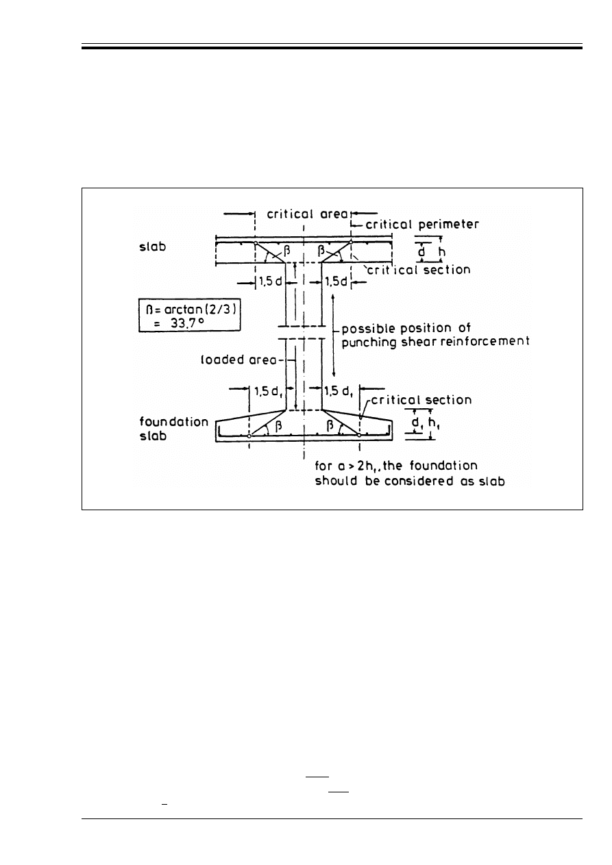
ENV 1992-1-1:1992
© BSI 12-1999
93
P(2) Punching shear may result from a concentrated load or reaction acting on a relatively small area,
called the “loaded area”, of a slab or of a foundation.
(3) An appropriate design model for checking punching shear failure at the ultimate limit state is shown
in Figure 4.16.
P(4) The shear resistance shall be checked along a defined critical perimeter. Outside the critical perimeter
the slab has to satisfy the requirements of section 4.3.2.
(5) In slabs subjected to punching shear an enhancement of shear resistance in accordance with
Equation (4.17) should not be carried out. In foundation slabs, the applied shear may be reduced to allow
for the soil reaction within the critical perimeter.
P(6) The flexural strength of the slab shall also be checked independently in accordance with 4.3.1.
P(7) If the thickness of a slab or foundation is not sufficient to ensure adequate punching shear resistance,
shear reinforcement, column heads or other types of shear connector shall be provided.
(8) The rules in this section also apply to waffle slabs with a solid section around the loaded area provided
that the solid area extends at least 1.5d beyond the critical perimeter.
(9) The amount of longitudinal tensile reinforcement in two perpendicular directions, x and y should be
greater than 0.5 %, calculated allowing for any differences in effective depth in the two directions.
(10) The force component parallel to V
Sd
due to inclined prestressed tendons placed inside the critical area
may be taken into account according to 4.3.2.4.6.
4.3.4.2
Scope and Definitions
4.3.4.2.1 Loaded area
(1) The provisions of this section are applicable to the following types of loaded area:
a) Shape (d denotes the average effective depth of the slab):
— circular, with diameter not exceeding |3.5 d|
— rectangular, with perimeter not exceeding |11 d| and the ratio of length to breadth not
exceeding |2|
Figure 4.16 — Design model for punching shear at the ultimate limit state
Licensed copy:Heriot Watt University, 20/04/2004, Uncontrolled Copy, © BSI
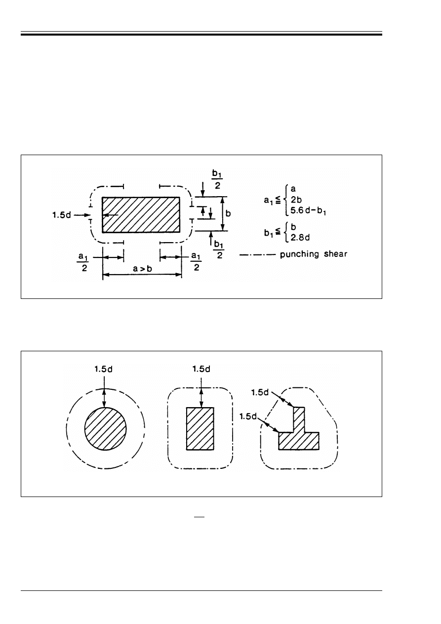
ENV 1992-1-1:1992
94
© BSI 12-1999
— any shape, the limiting dimensions being fixed by analogy with the shapes mentioned above;
d) The loaded area is not so close to other concentrated forces that their critical perimeters
intersect — nor in a zone subjected to significant shear forces of a different origin.
(2) If the conditions in 1) a) above are not satisfied for wall or rectangular column supports, since the shear
force in wall-shaped supports are concentrated in the corners, the critical perimeters according to
Figure 4.17 only should be taken into account, in the absence of a more detailed analysis
4.3.4.2.2 Critical perimeter
(1) The critical perimeter for circular or rectangular loaded areas located away from unsupported edges is
defined as a perimeter surrounding the loaded area and at a defined distance from it. It is assumed to
be 1.5d. See Figure 4.18.
(2) For loaded areas situated near openings, if the shortest distance between the perimeter of the loaded
area and the edge of the opening does not exceed |6 d|, that part of the critical perimeter contained
between two tangents drawn to the outline of the opening from the centre of area of the loaded area is
considered to be ineffective. See Figure 4.19.
Figure 4.17 — Application of punching provisions in non-standard cases
Figure 4.18 — Critical perimeter round loaded areas located away from an
unsupported edge
Licensed copy:Heriot Watt University, 20/04/2004, Uncontrolled Copy, © BSI
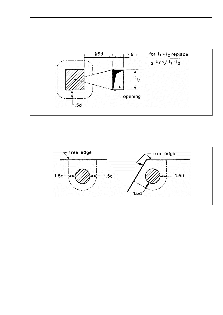
ENV 1992-1-1:1992
© BSI 12-1999
95
(3) For a loaded area situated near an unsupported edge or a corner, the critical perimeter should be taken
as shown in Figure 4.20, if this gives a perimeter (excluding the unsupported edges) less than that obtained
from (1) and (2) above.
(4) For loaded areas situated near or on an unsupported edge or near or on a corner, i.e. at a distance less
than d , special edge reinforcement along the edge is always required, (see 5.4.3.2.4).
4.3.4.2.3 Critical area
(1) The critical area is the area within the critical perimeter.
4.3.4.2.4 Critical section
(1) The critical section is the section which follows the critical perimeter and extends over the effective
depth, d. For slabs of constant depth, the critical section is perpendicular to the middle plane of the slab.
For slabs of variable depth (e.g. the foundation slab in Figure 4.16), it is assumed to be perpendicular to
the tension face.
4.3.4.3
Design method for checking punching shear
(1) The method for punching shear design set out in the following sections is based on three values of the
design shear resistance at the critical perimeter:
Figure 4.19 — Critical perimeter near an opening
Figure 4.20 — Critical sections near unsupported edges
V
Rd1
— the design shear resistance per unit length of the critical perimeter, for a slab without shear
reinforcement.
V
Rd2
— the maximum design shear resistance per unit length of the critical perimeter, for a slab
with shear reinforcement.
V
Rd3
— the design shear resistance per unit length of the critical perimeter, for a slab with shear
reinforcement.
Licensed copy:Heriot Watt University, 20/04/2004, Uncontrolled Copy, © BSI
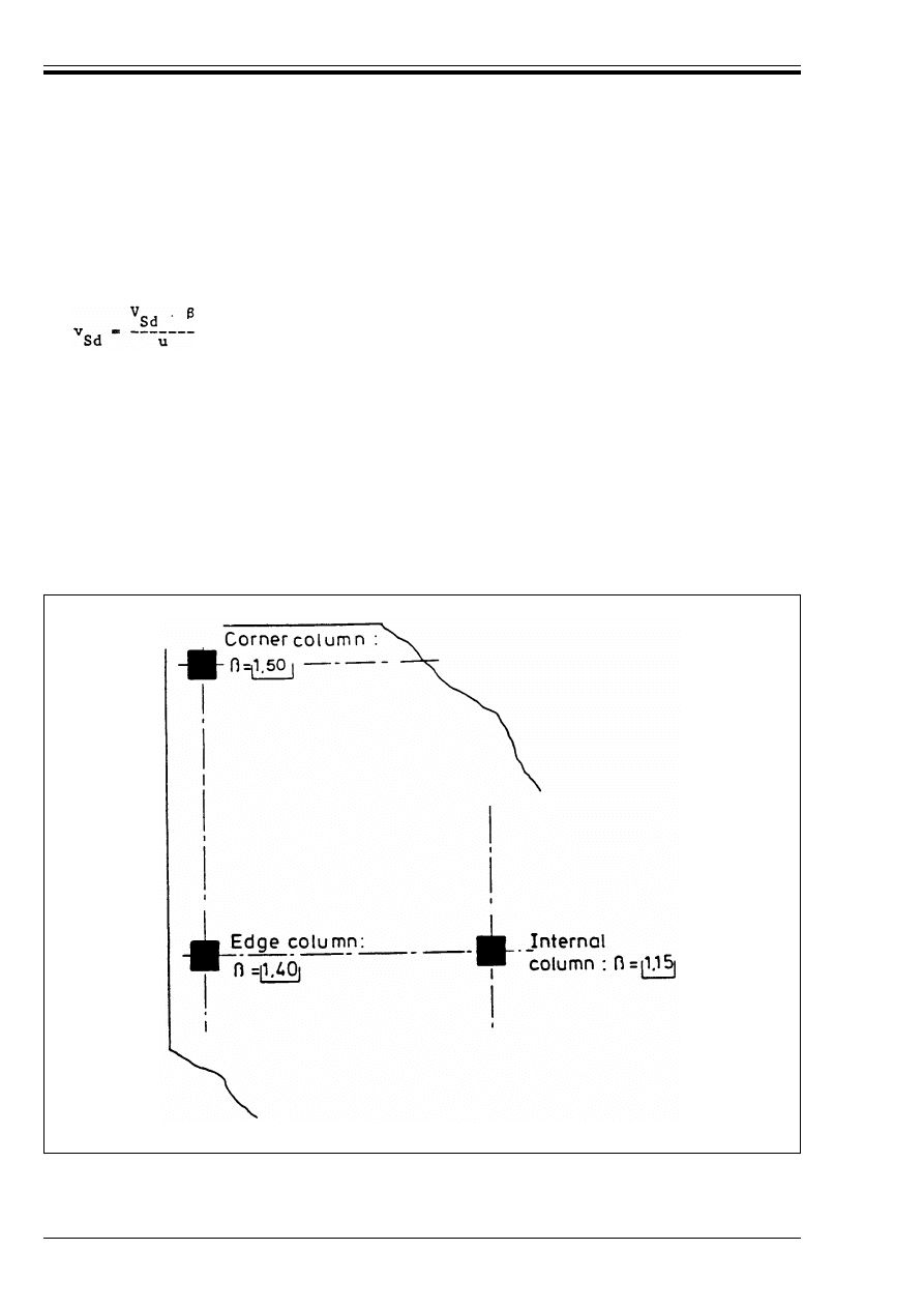
ENV 1992-1-1:1992
96
© BSI 12-1999
(2) No shear reinforcement is required if v
Sd
k v
Rd1
(3) If v
Sd
exceeds v
Rd1
, shear reinforcement or other forms of shear connector, where their application can
be justified, should be provided such that
v
Sd
r v
Rd3
(4) In the case of a concentrated load or support reaction, the applied shear per unit length is
(4.50)
where
V
sd
is the total design shear force developed. In a slab this is calculated along the perimeter u. For a
foundation this is calculated along the perimeter of the base of the truncated punching shear
cone, assumed to form at 33.7°, provided this falls within the foundation.
u
is the perimeter of the critical section.
"
is a coefficient which takes account of the effects of eccentricity of loading. In cases where no
eccentricity of loading is possible, " may be taken as 1.0. In other cases, the values given in
Figure 4.21 may be adopted. Based on a more rigorous analysis, other values for " may be used,
when associated with appropriate methods for ensuring the anchorage of the reinforcement at
the edge of the slab.
Figure 4.21 — Approximate values for "
Licensed copy:Heriot Watt University, 20/04/2004, Uncontrolled Copy, © BSI
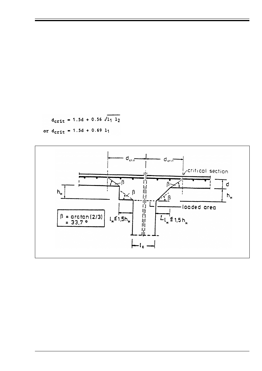
ENV 1992-1-1:1992
© BSI 12-1999
97
4.3.4.4
Slabs with variable depth
(1) For slabs with circular column heads for which l
H
< 1.5h
H
(see Figure 4.22) a check in accordance
with 4.3.4.3 is only required on the critical section outside the column head. The distance of this section
from the centroid of the column, d
crit
, may be taken as:
For a rectangular column with a rectangular head with overall dimensions l
1
,
and l
2
(l
1
= l
c1
+ 2l
H1
; l
2
= l
c2
+ 2l
H2
, l
1
r l
2
), d
crit
may be taken as the lesser of:
(2) For slabs with column heads where l
H
> 1.5(d + h
H
) (see Figure 4.23), the critical sections both within
the head and in the slab should be checked.
(3) The provisions of 4.3.4.3 apply for checks within the column head with d taken as d
H
(see Figure 4.23
for definition of d
H
).
(4) The distances from the centroid of the column to the critical sections in Figure 4.23 may be taken as:
(5) For column heads where 1.5 h
H
< l
H
< 1.5(h
H
+ d), the distance from the centroid of the column to the
critical section may be taken as:
d
crit
= 1.5d + l
H
+ 0.5 l
c
(4.51)
where l
H
is the distance from the column face to the edge of the column head
l
c
is the diameter of a circular column.
(4.52)
Figure 4.22 — Slab with column heads where l
H
< 1.5 h
H
d
crit,ex
= l
H
+ 1.5d + 0.5 l
c
(4.53)
d
crit,in
= 1.5 (d + h
H
) + 0.5 l
c
(4.54)
d
crit
= 1.5 l
H
+ 0.5 l
c
.
(4.55)
Licensed copy:Heriot Watt University, 20/04/2004, Uncontrolled Copy, © BSI
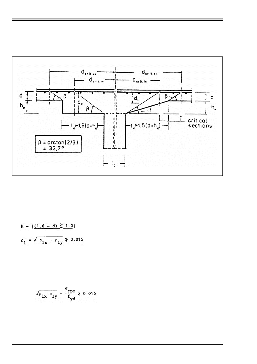
ENV 1992-1-1:1992
98
© BSI 12-1999
4.3.4.5
Shear resistance
4.3.4.5.1 Slabs or foundations without punching shear reinforcement
(1) The shear resistance per unit length v
Rd1
of non-prestressed slabs is given by:
(2) For prestressed slabs, Equation (4.56) applies, with:
Figure 4.23 — Slab with enlarged column head Where l
H
> 1.5 (d + h
H
)
5
Rd1
= Ù
Rd
k (1.2 + 40 @
1
)d
(4.56)
where
Ù
Rd
is given in Table 4.8, Section 4.3.2.
(d in metres)
@
lx
and @l
ly
relate to the tension steel in x and y directions respectively.
d = (d
x
+ d
y
)/2
d
x
and d
y
are the effective depths of the slab at the points of intersection between the design failure
surface and the longitudinal reinforcement, in the x and y directions respectively.
@
1
=
B
cpo
= N
pd
/A
c
f
yd
= design yield stress of the reinforcement
N
pd
= prestressing force corresponding to the initial value without losses (equivalent to P
mo
in 2.5.4
and 4.2.3). If the prestressing force is different in the prestressing directions, the average value
is used. N
pd
should be calculated with *
p
= 0.9.
Licensed copy:Heriot Watt University, 20/04/2004, Uncontrolled Copy, © BSI
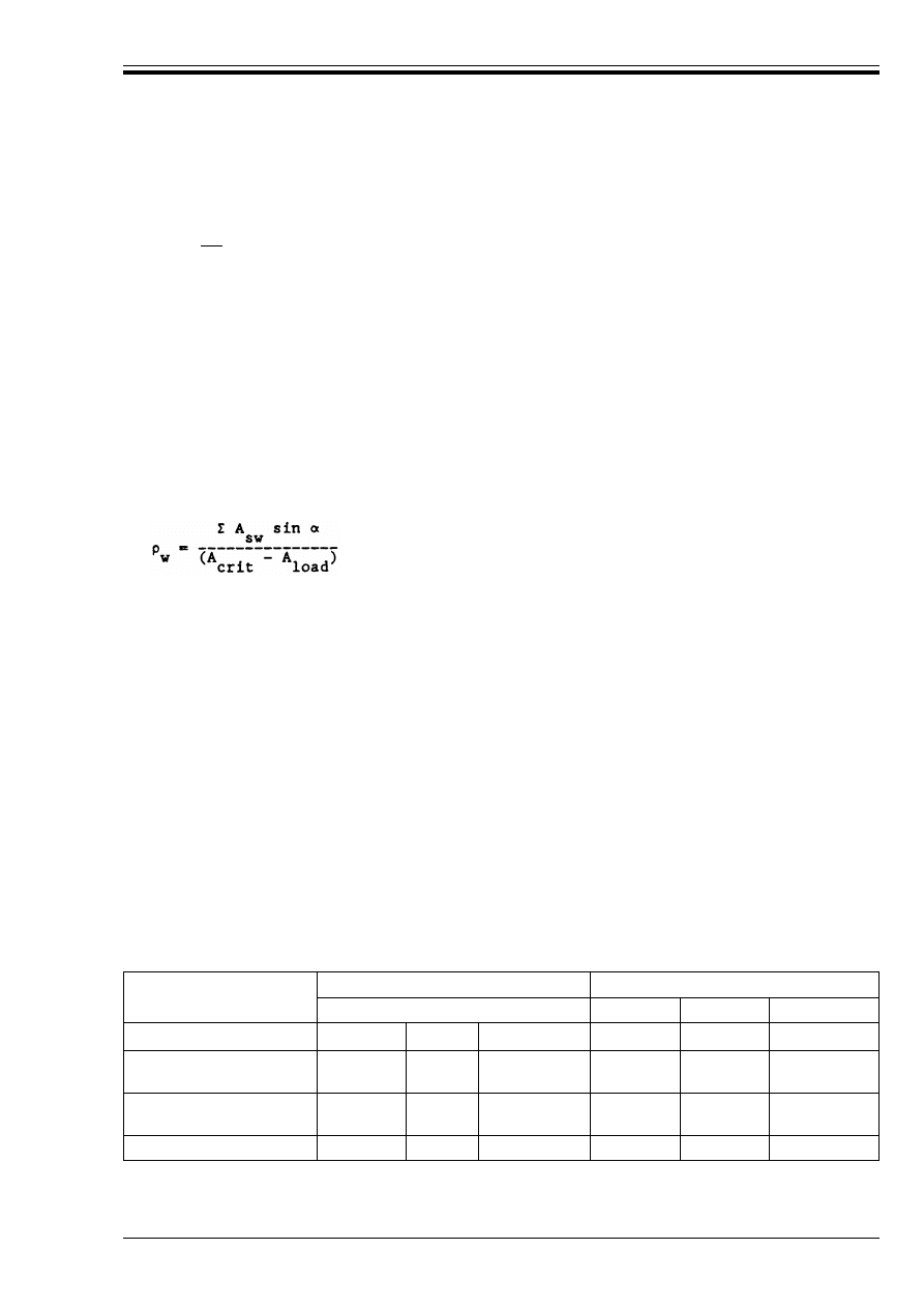
ENV 1992-1-1:1992
© BSI 12-1999
99
4.3.4.5.2 Slabs containing punching shear reinforcement
(1) In slabs containing shear reinforcement the shear resistances are given by:
where C A
sw
f
yd
sin! is the sum of the components of the design forces in the shear reinforcement in the
direction of the applied force, ! being the angle between the reinforcement and the plane of the slab.
For other types of shear reinforcement (e.g. shearheads), v
Rd3
may be determined by test or taken from
appropriate documents.
(2) Shear reinforcement should be provided within the critical area.
(3) Where necessary the punching shear resistance outside the shear reinforced area should be checked by
considering further critical perimeters.
(4) Detailing requirements for punching shear reinforcement are given in 5.4.3.3. Minimum shear
reinforcement should be provided in accordance with 5.4.3.3. The verification of Equation (5.16) can be
done by taking into account the total amount of punching shear reinforcement — placed between the
critical perimeter and the loaded area — as follows
(5) Flat slabs containing shear reinforcement should have a minimum depth of 200 mm [see 5.4.3.3(1)
4.3.4.5.3 Minimum design moments for slab-column connections subjected to eccentric loading
(1) To ensure that the punching shear resistance defined by Equations (4.56), (4.57) and (4.58) can develop,
the slab should be designed for minimum bending moments per unit width, m
Sdx
and m
Sdy
in the x and y
direction, unless structural analysis leads to higher values (see Figure 4.24). In the absence of other
provisions, Equation (4.59) should be satisfied:
(2) In checking the corresponding resisting moments, only those reinforcing bars should be taken into
account, which are appropriately anchored beyond the critical area (Figure 4.25).
Table 4.9 — Moment coefficient n for Equation (4.59)
v
Rd2
= |1.6| v
rd1
(4.57)
v
Rd3
= v
Rd1
+ C A
sw
f
yd
sin!/u
(4.58)
where:
A
crit
is the area within the critical perimeter
A
load
is the area within the loaded area (See Figure 4.16)
m
Sdx
(or m
Sdy
) T n.V
Sd
(4.59)
where
V
Sd
denotes the shear developed
n
is the moment coefficient given in Table 4.9.
Position of column
n for m
Sdx
n for m
Sdy
top
bottom
effective width
top
bottom
effective width
Internal column
– 0.125
0
0.3 l
y
– 0.125
0
0.3 l
x
Edge columns, edge of
slab parallel to x-axis
– 0.25
0
0.15 l
y
– 0.125
+ 0.125
(per m)
Edge columns edge of
slab parallel to y-axis
– 0.125
+ 0.125
(per m)
– 0.25
0
0.15.l
x
Corner column
– 0.5
+ 0.5
(per m)
+ 0.5
– 0.5
(per m)
Licensed copy:Heriot Watt University, 20/04/2004, Uncontrolled Copy, © BSI
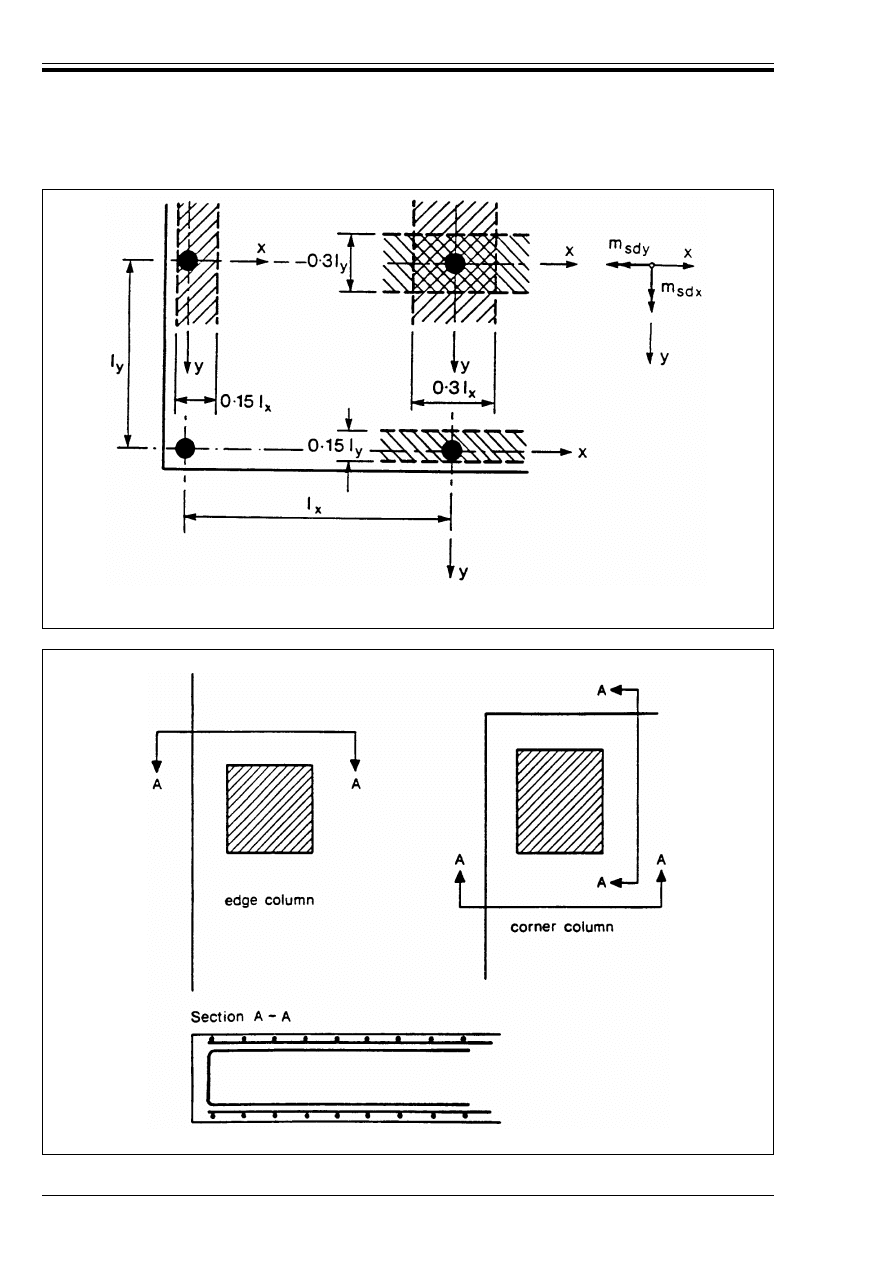
ENV 1992-1-1:1992
100
© BSI 12-1999
Figure 4.24 — Bending moments m
Sdx
and m
Sdy
in slab-column joints subjected to
eccentric loading, and effective width for resisting these moments
Figure 4.25 — Detailing of reinforcement over edge and corner columns
Licensed copy:Heriot Watt University, 20/04/2004, Uncontrolled Copy, © BSI

ENV 1992-1-1:1992
© BSI 12-1999
101
4.3.5 Ultimate limit states induced by structural deformation (buckling)
4.3.5.0
Notation (See also 1.6 and 1.7)
4.3.5.1
Scope and definitions
P(1) This section refers to slender structures or slender members mainly subjected to compression whose
load carrying capacity is significantly influenced by their deformations (second order effects).
P(2) The principles given in this section apply to linear reinforced and prestressed concrete members
subjected to axial compression, with or without bending, for which the effects of torsion can be neglected.
P(3) These principles may also be applied to other types of structural member, such as walls, shells, slender
beams in which lateral buckling of the compression zone may occur, deep beams or other exceptional
structures or members in which significant local deformations may arise.
(4) Rules are given in 4.3.5.2 to 4.3.5.6 and Appendix 3 for slender compression members and for lateral
buckling of slender beams in 4.3.5.7.
1/r
Curvature at the critical section at the base of a model column
I
b
Moment of inertia (gross section) of a beam
I
col
Moment of inertia (gross-section) of a column
K
1
Reduction factor for the calculation of the second order eccentricity e
2
(Equation 4.68)
K
2
Coefficient, taking account of decrease in curvature (1/r) due to increasing axial force
(Equation 4.71)
M
Rd
Design resisting moment
M
Sd1
First order applied moment
N
Rd
Resisting design axial compression force
N
ud
Design ultimate capacity of the section subjected to axial load only
e
2
Second order eccentricity
e
a
Additional eccentricity covering the effects of geometrical imperfections
e
e
Equivalent eccentricity (Equations 4.65 and 4.66 and Figure 4.29)
e
o
First order eccentricity
e
o1
, e
o2
Values of the first order eccentricity of the axial load at the ends of the member, denoted so
that |e
o1
| r |e
o2
|
e
tot
Total eccentricity
e
y
Eccentricity in the y direction
e
z
Eccentricity in the z direction
k
A
or
k
B
Coefficients describing the rigidity of restraint at the column ends
l
col
Height of column measured between idealised centres of restraint
l
ot
Length of a compression flange measured between lateral supports (Equation 4.77)
!
Factor taking into account the conditions of restraint of the beam at the opposite end
"
l
o
/1
col
(
yd
Design yield strain of the steel reinforcement
2
Slenderness ratio
2
crit
Critical slenderness ratio
5
u
Longitudinal force coefficient for an element
Licensed copy:Heriot Watt University, 20/04/2004, Uncontrolled Copy, © BSI

ENV 1992-1-1:1992
102
© BSI 12-1999
(5) In compression members, the influence of second order effects should be considered if the increase
above the first order bending moments due to deflections exceeds |10 %|. This may be assumed to be the
case where the slenderness of the structure or structural members considered exceed the limits given
in 4.3.5.3 below or in Appendix 3, clause A3.2.
4.3.5.2
Design procedures
P(1) Design for structural stability taking account of second order effects shall ensure that, for the most
unfavourable combinations of actions at the ultimate limit state, loss of static equilbrium (locally or for the
structure as a whole) does not occur or the resistance of individual cross-sections subjected to bending and
longitudinal force are not exceeded.
P(2) The structural behaviour shall be considered in any direction in which failure due to second order
effects may occur.
P(3) Possible uncertainties in the restraints at connections should be considered. Material properties shall
be assumed to have their design values (see 2.3.3.2) and corresponding deformation properties shall be
used throughout.
(4) For normal building structures, the design procedures set out in the following clauses consist of the
following three stages.
a) The structure or members are classified
b) For the classification of structure, the necessity to consider second order effects is established by
comparing the slenderness with limits set out in the appropriate clauses below.
This applies:
— for the structure as a whole if it is a sway structure
— for the individual columns considered as isolated columns. (see 4.3.5.5.3)
c) Where it is established that second order effects should be considered, design rules are given for
columns in 4.3.5.4, 4.3.5.5 and 4.3.5.6. Rules for slender beams are given in 4.3.5.7.
For more detailed information on the design procedures, see the flow charts in Appendix 3.
(5) More rigorous design approaches are set out in Appendix 3.
4.3.5.3
Classification of structures and structural elements
4.3.5.3.1 General
P(1) For the purpose of design calculations structures or structural members may be classified as braced
or unbraced depending on the provision or not of bracing elements and as non-sway or sway depending on
their sensitivity to second order effects due to lateral displacements.
P(2) Similarly, isolated columns are classified as slender or non-slender.
4.3.5.3.2 Bracing elements and braced structures
(1) A bracing element is a structural element which has a high flexural and/or shear stiffness and which is
completely or partially fixed (restrained) to the foundation. A bracing element or a system of bracing
elements should be sufficiently stiff to attract and transmit to the foundations all horizontal loads acting
on the structure and to ensure the stability of the braced sub-assembly.
(2) In general, the design of bracing elements may be based on first order analysis. However, a second order
analysis may be necessary where the bracing elements are relatively flexible. [see 4.3.5.1(5)].
(3) Structures with bracing elements which satisfy the requirements in (1) above are classified as braced.
4.3.5.3.3 Non-sway structures
(1) Structures or structural elements, with or without bracing elements, for which the influence of
displacements of the connections upon the design moments and forces may be neglected are classified as
non-sway. Otherwise they are classified as sway.
(2) Braced building structures, where the bracing is provided by substantial shear walls or core structures,
may be assumed to be non-sway. In other cases, structures may be classified by application of the
provisions of Appendix 3, clause A3.2.
— as braced or unbraced
and — as sway or non-sway (see 4.3.5.3.1 to 4.3.5.3.4)
Licensed copy:Heriot Watt University, 20/04/2004, Uncontrolled Copy, © BSI
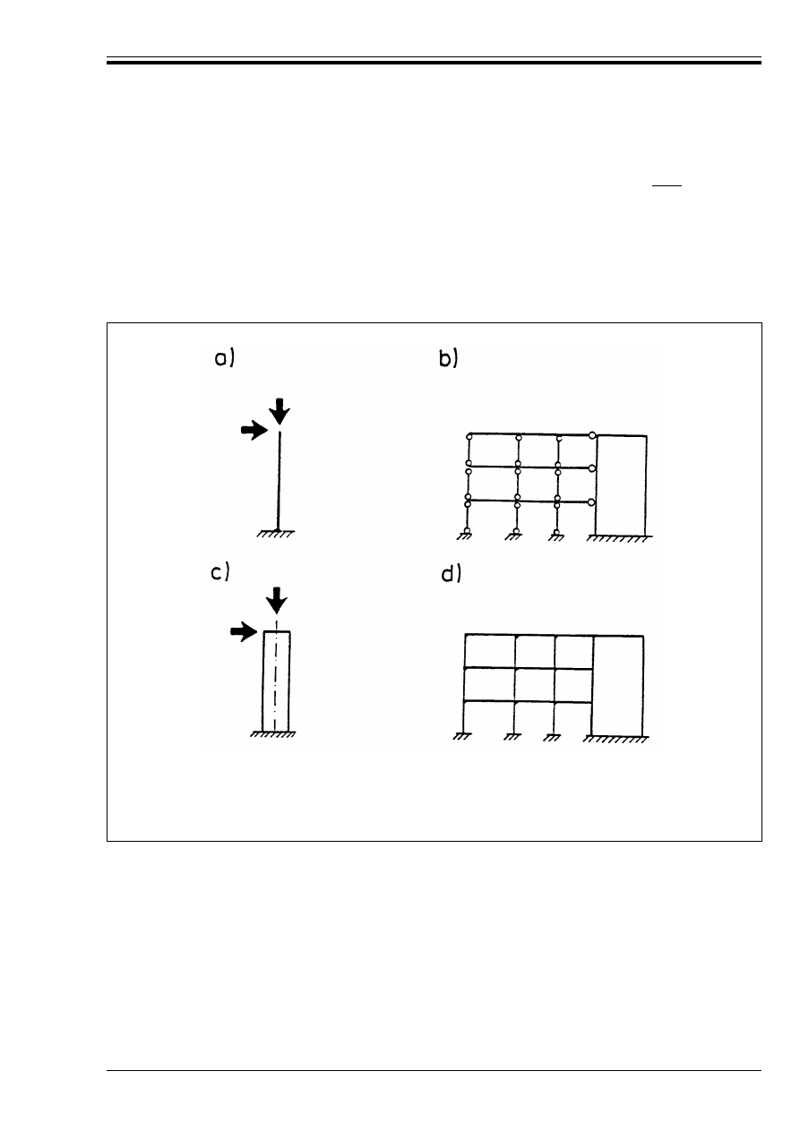
ENV 1992-1-1:1992
© BSI 12-1999
103
(3) Frames may be classified as non-sway if the first order displacements of the connections do not increase
the effects of actions calculated without considering these displacements by more than |10 %|. Generally
it is sufficient to consider only the relevant bending moments. [See 2.5.1.4].
4.3.5.3.4 Isolated columns
(1) These may be:
— isolated compression members [see Figure 4.26 a) and Figure 4.26 b)
— compression members which are integral parts of a structure but which are considered to be isolated
for design purposes (see e.g. 4.3.5.5.1). See Figure 4.26 c) and Figure 4.26 d).
a) Individual isolated column
b) columns with articulations in a non-sway structure
c) slender bracing element considered as isolated column
d) columns with restrained ends in a non-sway structure
Figure 4.26 — Types of isolated columns
Licensed copy:Heriot Watt University, 20/04/2004, Uncontrolled Copy, © BSI
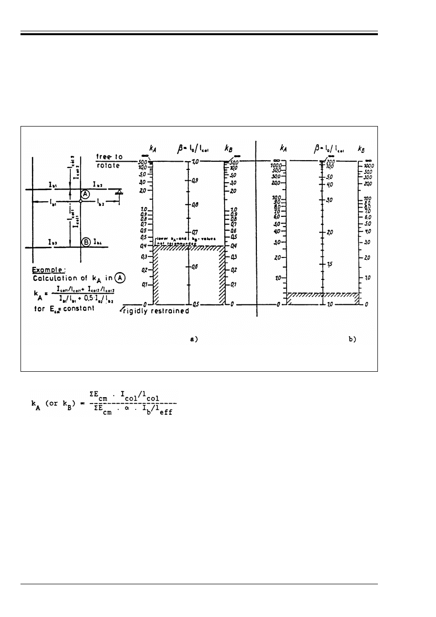
ENV 1992-1-1:1992
104
© BSI 12-1999
4.3.5.3.5 Slenderness of isolated columns
(1) For buildings, the effective height or length of a column l
o
= ".l
col
can be determined by means of
Figure 4.27 below in which the coefficients k
A
and k
B
denote the rigidity of restraint at the column ends:
[a) Non-sway frame
b) Sway-frame]
Figure 4.27 — Nomograms for the calculation of the effective length
(4.60)
where
E
cm
modulus of elasticity of the concrete (see 3.1.2.5.2)
I
col
, I
b
moment of inertia (gross section) of the column or beam respectively
l
col
height of the column measured between centres of restraint
l
eff
effective span of the beam
!
factor taking into account the conditions of restraint of the beam at the opposite end:
! = 1.0
opposite end elastically or rigidly restrained
! = 0.5
opposite end free to rotate
! = 0
for a cantilever beam.
Licensed copy:Heriot Watt University, 20/04/2004, Uncontrolled Copy, © BSI

ENV 1992-1-1:1992
© BSI 12-1999
105
(2) Isolated columns are considered slender if the slenderness ratio of the column considered exceeds 25
or 15/ß5
u
, whichever is the greater, where:
4.3.5.4
Imperfections
P(1) Allowance shall be made in the design for the uncertainties associated with the prediction of second
order effects and, in particular, dimensional inaccuracies and uncertainties in the position and line of
action of the axial loads. In the absence of other adequate provisions, this may be achieved by the use of
equivalent geometrical imperfections.
(2) For frame structures an inclination 5 of the complete structure (bracing elements and braced
sub-assembly) from the vertical is defined in 2.5.1.3.
(3) For isolated elements, the equivalent geometrical imperfections may be introduced by increasing the
eccentricity of the longitudinal force by an additional eccentricity e
a
, acting in the most unfavourable
direction:
4.3.5.5
Specific data for different types of structure
4.3.5.5.1 Non-sway frames
P(1) Individual non-sway compression members shall be considered to be isolated elements and be
designed accordingly.
P(2) Bracing elements or, in non-sway frames without bracing elements, the individual compression
members shall be designed for the relevant horizontal forces and vertical loads taking account of the
equivalent geometrical imperfections defined in 2.5.1.3 and 4.3.5.4 respectively.
(3) For individual compression members, the design rules for isolated columns (see 4.3.5.5.3) apply. The
effective length l
o
may generally be determined according to 4.3.5.3.5.
4.3.5.5.2 Sway frames
(1) Information on sway frames is given in Appendix 3.
4.3.5.5.3 Isolated columns
P(1) Second order effects including geometrical imperfections and deformations due to creep, if they affect
the structural stability significantly, shall be taken into account in the design of slender isolated
compression members.
(2) Isolated columns in non-sway structures need not be checked for second order effects if the slenderness
ratio 2 is less than or equal to the value give in Equation (4.62) even though the column may be classified
as slender by 4.3.5.3.5.
e
o1
and e
o2
are the eccentricities of the axial load at the ends of the member and it is assumed
that |e
o1
| r |e
o2
|
5
u
the longitudinal force coefficient for the element:
5
u
= N
Sd
/(A
c
· f
cd
)
2
slenderness ratio: 2 = l
o
/i
l
o
effective height or length of the vertical element. l
o
is generally derived using the elastic
buckling theory. For frame structures, the column to which l
o
refers needs to be defined
carefully.
i
radius of gyration.
e
a
= 5 · l
o
/2
(4.61)
where
l
o
denotes the effective length of the isolated element (see 4.3.5.3.5)
5
inclination from the vertical calculated using Equation (2.10).
2
crit
= 25.(2 – e
o1
/e
o2
)
(4.62)
Licensed copy:Heriot Watt University, 20/04/2004, Uncontrolled Copy, © BSI
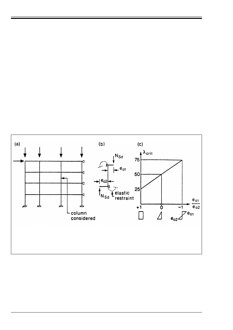
ENV 1992-1-1:1992
106
© BSI 12-1999
In this case, the column ends should be designed for at least the conditions given by Equations (4.63)
and (4.64).
where N
Rd
is the design resisting axial force in compression and M
Rd
is the design resisting moment.
Equation (4.62) should be used only if the column is not subjected to transverse loads between its two
ends.
The criterion defined by Equation (4.62) is shown graphically in Figure 4.28.
For the design of columns see 4.3.5.6.
P(3) For columns bent dominantly about one principal axis, the possibility of failure due to second order
effects about the second principal axis should be checked.
(4) For this check the initial eccentricity e
o
in the direction of the second principal axis should be taken as
zero and the second order effects should be calculated by using the slenderness ratio 2 related to this axis.
The additional eccentricity defined in 4.3.5.4(3) and, where relevant, creep deformations should be taken
into account.
P(5) Principles (1) and (3) above also apply to compression members subjected to bi-axial bending in which
the effects of torsion are negligible.
(6) If the first order eccentricity e
o
of the axial force in the direction of the first principal axis
exceeds e
o
> 0.2 h, the check in the direction of the second principal axis should be based on the reduced
section depth h½ as defined in 4.3.5.6.4(3).
N
Rd
= N
Sd
(4.63)
M
Rd
= N
Sd ·
h/20
(4.64)
a) Structural system
b) Idealisation of the column considered
c) Critical slenderness ratio 2
crit
Figure 4.28 — Slenderness limits for isolated members with rigidly or elastically
restrained ends in non-sway structures
Licensed copy:Heriot Watt University, 20/04/2004, Uncontrolled Copy, © BSI
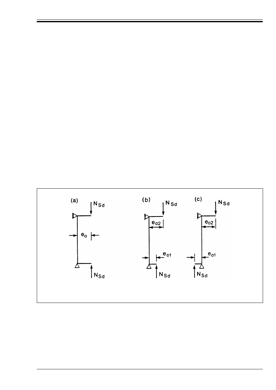
ENV 1992-1-1:1992
© BSI 12-1999
107
4.3.5.6
Simplified design methods for isolated columns
4.3.5.6.1 General
(1) For buildings, a design method may be used which assumes the compression members to be isolated and
adopts a simplified shape for the deformed axis of the column. The additional eccentricity is then calculated
as a function of the slenderness.
4.3.5.6.2 Total eccentricity
(1) The total eccentricity attributed to columns of constant cross-section (concrete and steel, ignoring laps)
in the most heavily stressed section (critical section) is given by:
a) First order eccentricities, equal at both ends [Figure 4.29(a)]:
b) Where the first order eccentricites are different at both ends [Figure 4.29(b), Figure 4.29(c)]
For columns of constant cross-section (concrete and steel ignoring laps) subjected to first order
moments varying linearly along their length and having eccentricities at their ends which differ in
value and/or sign, an equivalent eccentricity e
e
should be used in Equation (4.65), instead of e
o
, for the
critical section.
e
tot
= e
o
+ e
a
+ e
2
(4.65)
where
e
o
first order eccentricity:
e
o
= M
Sd1
/N
Sd
M
Sd1
first order applied moment
N
Sd
applied longitudinal force
e
a
additional eccentricity according to Equation (4.61)
e
2
second order eccentricity, using the approximate methods given
in 4.3.5.6.3 below, including any effects due to creep.
a) eccentricities equal at both ends
b) and c) eccentricities different at both ends
Figure 4.29 — Design model for the calculation of the total eccentricity
Licensed copy:Heriot Watt University, 20/04/2004, Uncontrolled Copy, © BSI
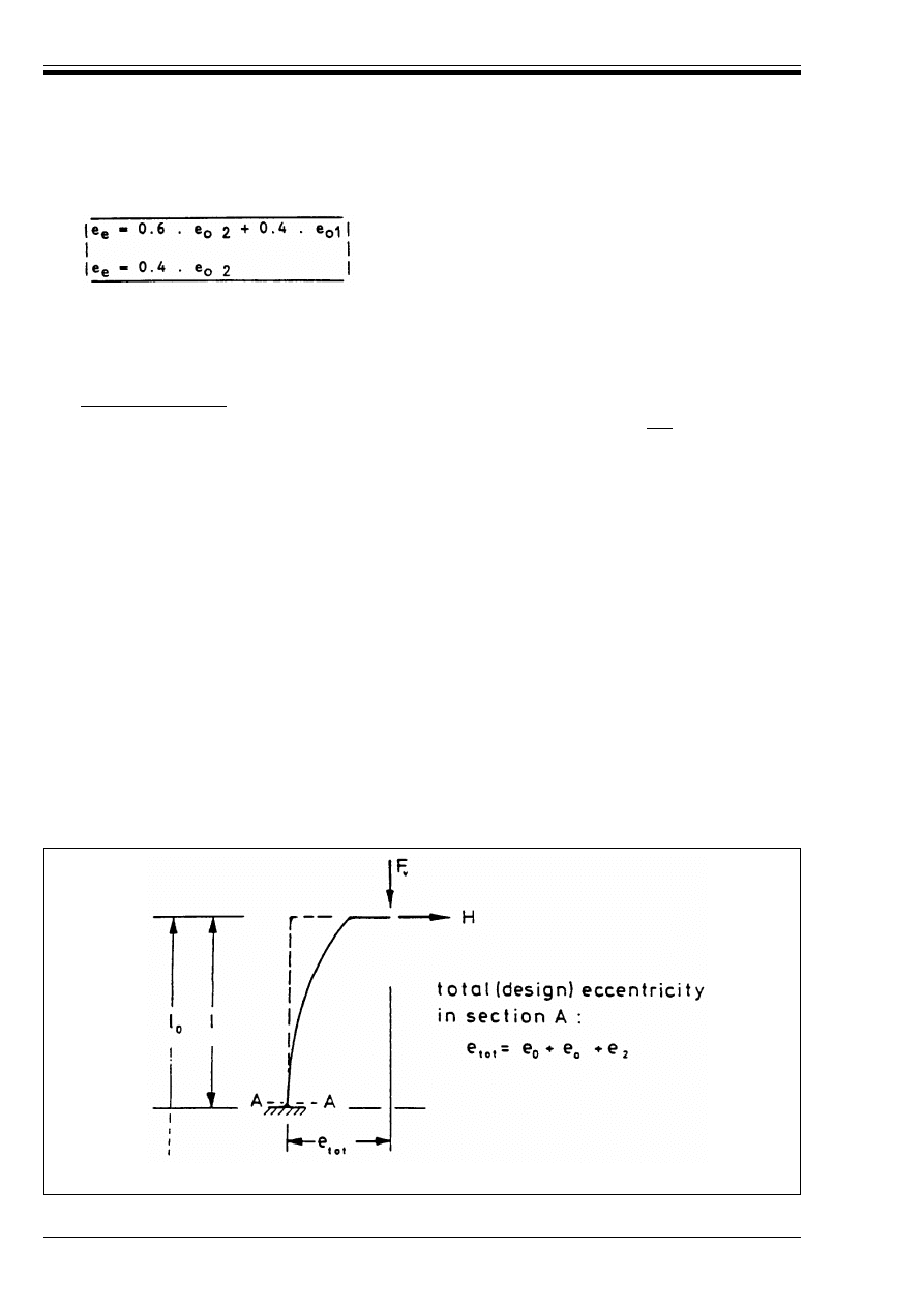
ENV 1992-1-1:1992
108
© BSI 12-1999
The equivalent eccentricity e
e
can be taken as the higher of the following values:
where e
o 1
and e
o 2
denote the first order eccentricities at the two ends, and
4.3.5.6.3 Model column method
a) Scope and definition
1) The design method which is described below relates to members where 2 < |140| and with
rectangular or circular cross-sections and in which the first order eccentricity satisfies the condition
e
o
T 0.1 h (h: depth of the cross section measured in the plane under consideration). For other shapes
of cross-section and for the eccentricities e
o
< 0.1 h, other appropriate approximations may be used.
2) A “model column” is a cantilever column which is:
— fixed at the base and free at the top (Figure 4.30):
— bent in simple curvature under loads and moments which give the maximum moments at the
base.
The maximum deflection, which equals the second order eccentricity, e
2
of such a column may be
assumed to be:
3) The stability is analysed on the basis of the curvature 1/r in the critical section at the base. This
curvature is derived from the equilibrium of the internal and external forces.
4) For creep effects, see Appendix 3 [A3.4 9)].
(4.66)
(4.67)
|e
o2
| T|e
o1
| [Figure 4.29(b) and Figure 4.29(c)]
(4.68)
e
2
= K
1
· l
2
o/10 · (1/r)
(4.69)
where l
o
is the effective length of the column
and 1/r is defined in 3) below
K
1
= 2/20 – 0.75 for 15 r 2 r 35
(4.70)
K
1
= 1 for 2 > 35
(4.71)
Figure 4.30 — Model column (notation)
Licensed copy:Heriot Watt University, 20/04/2004, Uncontrolled Copy, © BSI

ENV 1992-1-1:1992
© BSI 12-1999
109
b) Transformation of second order analysis to cross section design
5) In cases where great accuracy is not required, the curvature 1/r in Equation (4.69) may be derived
from
6) The coefficient K
2
in Equation (4.72) takes account of the decrease of the curvature 1/r with
increasing axial force and is defined by
4.3.5.6.4 Compression members with bi-axial eccentricities
(1) For members with rectangular cross sections, separate checks in the two principal planes y and z
(see Figure 4.31) are permissible if the ratio of the corresponding eccentricities e
y
/b and e
z
/h satisfy one of
the following conditions:
(i.e. that the point of application of N
Sd
is located in the hatched area in Figure 4.31). The eccentricities e
y
and e
z
are the first order eccentricities in directions of the section dimensions b and h respectively. They
need not include e
a
as defined in Equation (4.61). A refined analysis will be required if the stated conditions
are not met.
(2) For the two separate checks 4.3.5.3.5 (effective heights and slenderness limits), 4.3.5.5.3
and 4.3.5.6.2 — 4.3.5.6.3 apply analogously where the slenderness limits given in 4.3.5.3 are exceeded. The
geometrical imperfections defined in 4.3.5.4 should, however, be considered in the two planes.
(3) Where e
z
> 0.2 h (see Figure 4.32), separate checks are permissible only if the check for bending
about the minor axis of the cross section (z in Figure 4.31) is based on the reduced width h½ as shown
in Figure 4.32. The value h½ may be determined on the assumption of a linear stress distribution e.g. from:
(4) If the criterion in (1) above is not met, a refined analysis is necessary.
1/r = 2 · K
2
· ( y
d
/0.9 · d)
(4.72)
where
(
yd
is the design yield strain of steel reinforcement = f
yd
/E
s
d
is the effective depth of the cross-section in the expected direction of stability
failure.
K
2
= (N
ud
– N
Sd
)/(N
ud
– N
bal
) r 1
(4.73)
where
N
ud
is the design ultimate capacity of the section subjected to axial load only. It may be taken
as N
ud
= !.f
cd
.A
c
+ f
yd
.A
s
. [for ! see 4.2.1.3.3(11)]
N
Sd
the actual design axial force
N
bal
is the axial load which, when applied to a section, maximises its ultimate moment capacity.
For symmetrically reinforced rectangular sections, it may be taken as 0.4.f
cd
A
c
.
It will always be conservative to assume that K
2
= 1
either
(e
z
/h)/(e
y
/b) r 0.2
(4.74)
or
(e
y
/b)/(e
z
/h) r 0.2
(4.75)
N
Sd
/A
c
– N
Sd
· (e
z
+ e
az
)/Z
c
= 0
(4.76)
where:
N
Sd
longitudinal force, negative sign in compression.
Z
c
modulus of gross section.
e
az
additional eccentricity according to Equation (4.61) in the z direction.
Licensed copy:Heriot Watt University, 20/04/2004, Uncontrolled Copy, © BSI
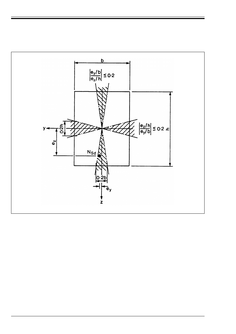
ENV 1992-1-1:1992
110
© BSI 12-1999
Figure 4.31 — Assumption for separate checks in the two principal planes
Licensed copy:Heriot Watt University, 20/04/2004, Uncontrolled Copy, © BSI
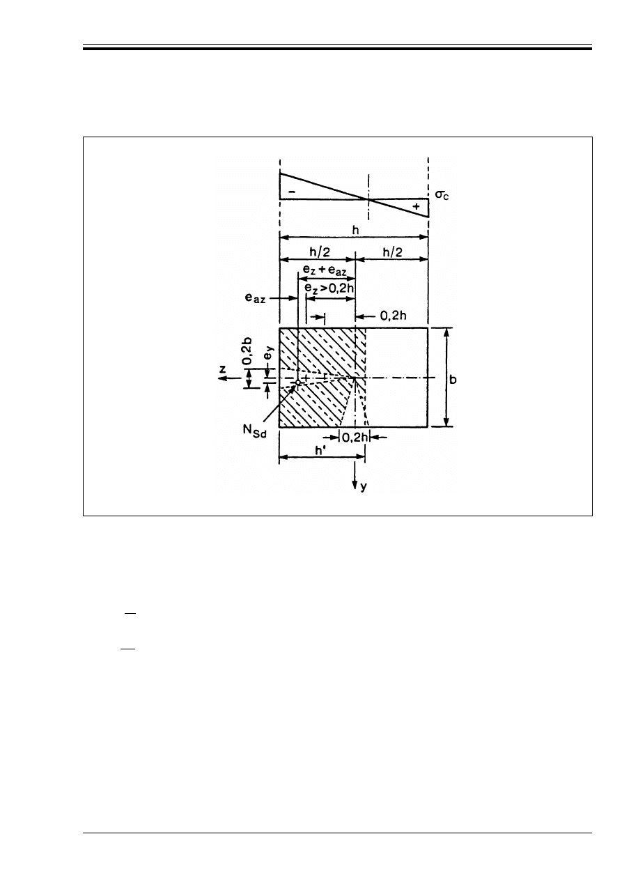
ENV 1992-1-1:1992
© BSI 12-1999
111
4.3.5.7
Lateral buckling of slender beams
P(1) Where the safety of beams against lateral buckling is in doubt, it shall be checked by an appropriate
method.
(2) The safety against lateral buckling of reinforced and prestressed concrete beams may be assumed to be
adequate if the requirements in Equation (4.77) are satisfied. Otherwise a more detailed analysis should
be carried out.
Figure 4.32 — Separate check in the y-direction if e
z
> 0.2 h
l
ot
< |50| b
and
(4.77)
h < |2.5| b
where:
b
width of the compression flange
h
total depth of the beam
l
ot
length of the compression flange measured between lateral supports.
Licensed copy:Heriot Watt University, 20/04/2004, Uncontrolled Copy, © BSI

ENV 1992-1-1:1992
112
© BSI 12-1999
4.4 Serviceability limit states
4.4.0 General
4.4.0.1
Notation (See also 1.6 and 1.7)
A
c.eff
Effective area of concrete in tension
A
ct
Area of concrete within the tension zone
A
s.req
Area of tension reinforcement required
A
s.prov
Area of tension reinforcement provided
V
cd
Design shear contribution of the concrete section (see 4.3.2.4.3)
f
ct.eff
The tensile strength of the concrete effective at the time when cracks are expected to occur
k
Coefficient which allows for the effects of non-uniform self-equilibrating stresses
k
c
Stress distribution coefficient
k
1
Coefficient to take account of the influence of the bond properties of bar on the crack
spacing
k
2
Coefficient to take account of the influence of the form of the strain distribution on the
crack spacing
S
rm
Average final crack spacing
S
rmx
}
S
rmy
}
Average final crack spacings in the x and y direction respectively
w
k
Design or characteristic crack width
!
Angle between the shear reinforcement and the longitudinal reinforcement (main steel)
"
Coefficient relating the average crack width to the design width
"
1
Coefficient taking account of the influence of the bond properties of bar on the average
strain
"
2
Coefficient taking account of the influence of the duration of the loading or of repeated
loading on the average strain
(
sm
Strain in the reinforcement taking account of tension stiffening
(
1
Greater tensile strain at the boundary of a section subject to eccentric tension
(
2
Lesser tensile strain at the boundary of a section subject to eccentric tension
"
Angle between the reinforcement in the x direction and the direction of the principal tensile
stress
Ì
s
Adjusted maximum bar diameter
*
Ì
s
Unadjusted maximum bar diameter (Table 4.11)
@
r
Effective reinforcement ratio
B
s
Stress in the tension reinforcement calculated on the basis of a cracked section
B
sr
Stress in the tension reinforcement calculated on the basis of a cracked section under
conditions of loading leading to formation of the first crack, e.g. B
ct
= f
ctm
Licensed copy:Heriot Watt University, 20/04/2004, Uncontrolled Copy, © BSI

ENV 1992-1-1:1992
© BSI 12-1999
113
4.4.0.2
Scope
P(1) This chapter covers the common serviceability limit states. These are:—
Other limit states (such as vibration) may be of importance in particular structures but these are not
covered in this code.
4.4.1 Limitation of stresses under serviceability conditions
4.4.1.1
Basic considerations
P(1) Excessive compressive stress in the concrete under the service load may promote the formation of
longitudinal cracks and lead to micro-cracking in the concrete or higher than predicted levels of creep. If
the proper functioning of a member is likely to be adversely affected by these, measures shall be taken to
limit the stresses to an appropriate level.
(2) Longitudinal cracks may occur if the stress level under the rare combination of loads exceeds a critical
value. Such cracking may lead to a reduction in durability. In the absence of other measures, such as an
increase in cover to reinforcement in the compressive zone or confinement by transverse reinforcement, it
may be appropriate to consider limiting the compressive stress to |0.6| f
ck
in areas exposed to
environments of exposure Class 3 or 4 (see Table 4.1).
(3) Creep may exceed the amount predicted using the methods given in 2.5.5 if the stress in the concrete
under the quasi-permanent loads exceeds |0.45| f
ck
. If creep is likely to significantly affect the
functioning of the member considered, the stress should be limited to this value. For reinforced concrete
flexural members, this check should be considered if the span/effective depth ratio exceeds 85 % of the
value given in 4.4.3.2 for the case considered. A check may be necessary at transfer in prestressed
elements.
(4) Durability requirements for prestressed concrete may impose other limits on the stresses in the
concrete; for example, that the section should remain in compression (see 4.4.2.1).
(5) Stress under anchorages and bearings. No check will be necessary under serviceability conditions
where the provisions of 2.5.3.7.4, and 5.4.6 or 5.4.8 have been complied with.
P(6) Stresses in the steel under serviceability conditions which could lead to inelastic deformation of the
steel shall be avoided as this will lead to large, permanently open, cracks.
(7) This requirement will be met provided that, under the rare combination of loads (see 2.3.4) the tensile
stress in ordinary reinforcement does not exceed |0.8| f
yk
. Where the stress is due only to imposed
deformations, a stress of |f
yk
| will be acceptable. The stress in prestressing tendons should not
exceed |0.75| f
pk
after allowance for losses.
4.4.1.2
Methods for checking stresses
P(1) In calculating the stress, account shall be taken of whether or not the section is expected to crack under
service loads and also of the effects of creep and shrinkage. Other indirect actions which could influence
the stress, such as temperature, may also need to be considered.
(2) The stress limitations given in 4.4.1.1 may generally be assumed to be satisfied without further
calculations provided:
a) the design for the ultimate limit state has been carried out in accordance with 4.3.
b) the minimum reinforcement provisions of 4.4.2.2 are satisfied.
c) detailing is carried out in accordance with Chapter 5.
d) not more than 30 % of redistribution has been carried out in the analysis for the ultimate limit state.
It should be noted that creep and shrinkage in partially prestressed members may lead to high stresses
in both normal reinforcement and prestressing tendons which could lead to fatigue problems.
(3) Long term effects may be ignored except for situations where more than 50 % of the stress arises from
quasi-permanent actions. In this situation, a modular ratio of 15 may be assumed.
— stress limitation
(see 4.4.1)
— crack control
(see 4.4.2)
— deflection control (see 4.4.3)
Licensed copy:Heriot Watt University, 20/04/2004, Uncontrolled Copy, © BSI

ENV 1992-1-1:1992
114
© BSI 12-1999
(4) Stresses are checked employing section properties corresponding to either the uncracked or the fully
cracked condition, whichever is appropriate.
(5) In general where the maximum tensile stress in the concrete calculated on the basis of an uncracked
section under the rare combination of loads exceeds f
ctm
(see Table 3.1), the cracked state should be
assumed.
(6) Where an uncracked section is used, the whole of the concrete section is assumed to be active and both
concrete and steel are assumed to be elastic in both tension and compression.
(7) Where a cracked section is used, the concrete is assumed to be elastic in compression but to be
incapable of sustaining any tension. (In checking stresses in accordance with these rules, no allowance
should be made for the stiffening effect of the concrete in tension after cracking).
(8) At least the minimum area of reinforcement given by 4.4.2.2 is required to satisfy the limitation on the
stress in ordinary bonded reinforcement under the action of restrained imposed deformations.
4.4.2 Limit states of cracking
4.4.2.1
General considerations
P(1) Cracking shall be limited to a level that will not impair the proper functioning of the structure or cause
its appearance to be unacceptable.
P(2) Cracking is almost inevitable in reinforced concrete structures subject to bending, shear, torsion or
tension resulting from either direct loading or restraint of imposed deformations.
P(3) Cracks may also arise from other causes such as plastic shrinkage or expansive chemical reactions
within the hardened concrete. Such cracks may be unacceptably large but their avoidance and control lie
outside the scope of this chapter.
P(4) Alternatively, cracks may be permitted to form without any attempt to control their width or be
avoided by measures, such as the provision of joints, which can accommodate the movement, provided they
do not impair the functioning of the structure.
P(5) Appropriate limits, taking account of the proposed function and nature of the structure and the costs
of limiting cracking, should be agreed with the client.
(6) in the absence of specific requirements (e.g. watertightness), it may be assumed that, for exposure
classes 2–4, limitation of the maximum design crack width to about |0.3| mm under the quasi-permanent
combination of loads (see 2.3.4) will generally be satisfactory for reinforced concrete members in buildings
with respect to appearance and durability. For exposure class 1, crack width has no influence on
durability and the limit could be relaxed if this was acceptable for other reasons.
(7) The durability of prestressed members may, for exposure classes 2–4, be more critically affected by
cracking (see 4.1). In the absence of more detailed requirements, the limitations in Table 4.10 are
considered to be generally satisfactory. The decompression limit requires that, under the frequent
combination of loads, all parts of the tendons or duct lie at least 25 mm within concrete in compression.
(8) Special crack limitation measures may be necessary for members subjected to exposure class 5. The
choice of appropriate measures will depend upon the nature of the aggressive chemical involved.
P(9) Limitation of cracks to acceptable widths is achieved by ensuring
a) that, at all sections likely to be subjected to significant tension due to restraint of imposed
deformations, whether or not the restraint is combined with direct loading, a minimum amount of
bonded reinforcement is present sufficient to ensure that yield of the reinforcement will not occur until
above the cracking load,
and
b) that bar spacings and diameters are limited in order to limit the crack width.
This also applies to parts of prestressed members where tension could develop in the concrete.
Licensed copy:Heriot Watt University, 20/04/2004, Uncontrolled Copy, © BSI
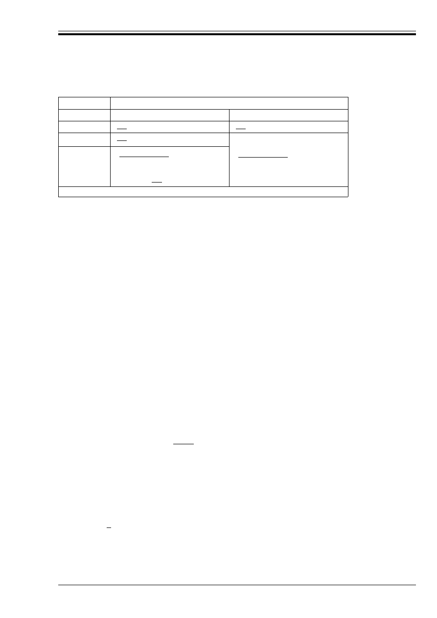
ENV 1992-1-1:1992
© BSI 12-1999
115
Table 4.10 — Criteria for prestressed members
4.4.2.2
Minimum reinforcement areas
P(1) In assessing the minimum area of reinforcement required to ensure controlled cracking in a member
or part of a member which may be subject to tensile stress due to the restraint of imposed deformations, it
is necessary to distinguish between two possible mechanisms by which such stress may arise. The two
mechanisms are:
i) restraint of intrinsic imposed deformations — where stresses are generated in a member due to
dimensional changes of the member considered being restrained (for example stress induced in a
member due to restraint to shrinkage of the member),
ii) restraint of extrinsic imposed deformations — where the stresses are generated in the member
considered by its resistance to externally applied deformations (for example where a member is stressed
due to settlement of a support).
P(2) It is also necessary to distinguish between two basic types of stress distribution within the member at
the onset of cracking. These are:
a) bending — where the tensile stress distribution within the section is triangular (i.e. some part of the
section remains in compression).
b) tension — where the whole of the section is subject to tensile stress.
(3) Unless more rigorous calculation shows a lesser area to be adequate, the required minimum areas of
reinforcement may be calculated from the relation given below:
Exposure class Design crack width, w
k
, under the frequent load combination
(mm)
Post-tensioned
Pre-tensioned
1
|0.2|
|0.2|
2
|0.2|
(
(
(|decompression|
(
(
(
3
4
(|decompression|
( or
(coating of the tendons
(and w
k
= |0.2|
NOTE for definition of decompression, see (7) above.
A
s
= k
c
k f
ct.ef
A
ct
/B
s
(4.78)
where:
A
s
= area of reinforcement within tensile zone
A
ct
= area of concrete within tensile zone. The tensile zone is that part of the section which is
calculated to be in tension just before formation of the first crack.
B
s
= the maximum stress permitted in the reinforcement immediately after formation of the crack.
This may be taken as |100 %| of the yield strength of the reinforcement, f
yk
. A lower value
may, however be needed to satisfy the crack width limits (see Table 4.11)
f
ct.eff
= the tensile strength of the concrete effective at the time when the cracks may first be expected
to occur. In many cases, such as where the dominant imposed deformation arises from
dissipation of the heat of hydration, this may be within 3–5 days from casting depending on the
environmental conditions, the shape of the member and the nature of the formwork. Values of
f
ct.ef
may be obtained from Table 3.1 by taking as the class the strength at the time cracking is
expected to occur. When the time of cracking cannot be established with confidence as being
less than 28 days, it is suggested that a minimum tensile strength
of |3| N/mm
2
be adopted.
k
c
= a coefficient which takes account of the nature of the stress distribution within the section
immediately prior to cracking. The relevant stress distribution is that resulting from the
combination of effects of loading and restrained imposed deformations.
= 1.0 for pure tension
Licensed copy:Heriot Watt University, 20/04/2004, Uncontrolled Copy, © BSI

ENV 1992-1-1:1992
116
© BSI 12-1999
Parts of sections distant from the main tension reinforcement, such as outstanding parts of a section or
the webs of deep sections, may be considered to be subjected to imposed deformations by the tension chord
of the member. For such cases, a value in the range 0.5 < k < 1.0 will be appropriate.
(4) The minimum reinforcement may be reduced or even be dispensed with altogether if the imposed
deformation is sufficiently small that it is unlikely to cause cracking. In such cases minimum
reinforcement need only be provided to resist the tensions due to the restraint.
P(5) In prestressed members and reinforced concrete members subject to compressive normal force the
minimum reinforcement area may be reduced below that necessary for ordinary reinforced concrete due to
the influence of:
— the increased flexural stiffness of the compression zone.
— the contribution of the prestressing tendons.
(6) In prestressed members, the minimum reinforcement for crack control is not necessary in areas where,
under the rare combination of actions and the relevant estimated characteristic value of prestress or
normal force, the concrete remains in compression
(7) If the conditions in (6) are not fulfilled, the required minimum area should be calculated according
to (3) above with the following values for k
c
.
For rectangular sections, the value of k
c
may be interpolated between 0.4 for pure bending without normal
force and zero when either:
a) the conditions just satisfy (6) above
or
b) where, under the action of the relevant estimated value of prestress, the depth of the tension zone,
calculated on the basis of a cracked section under the loading conditions leading to formation of the first
crack, does not exceed the lesser of h/2 or 0.5 m.
(8) Prestressing tendons may be taken into account as minimum reinforcement within a 300 mm square
surrounding the tendon, provided that the different bond behaviour of the tendons and reinforcement are
taken into account. In the absence of better information, this may be done by assuming prestressing
tendons to be 50 % effective.
4.4.2.3
Control of cracking without direct calculation
(1) For reinforced or prestressed slabs in buildings subjected to bending without significant axial tension,
measures specifically to control cracking are not necessary where the overall depth does not exceed 200 mm
and the provisions of 5.4.3 have been applied.
= 0.4 for bending without normal compressive force
For sections subject to normal force or prestress, see (7) below.
k
= a coefficient which allows for the effect of non-uniform self-equilibrating stresses.
Values of k for various situations are given below:
— tensile stresses due to restraint of intrinsic deformations generally
k = 0.8
(h r 30 cm k = 0.8
for rectangular sections
(
(h T 80 cm k = 0.5
— tensile stresses due to restraint of extrinsic deformations
k = 1.0
For box sections,
k
c
= 0.4 for the webs
= 0.8 for the tension chord
Licensed copy:Heriot Watt University, 20/04/2004, Uncontrolled Copy, © BSI
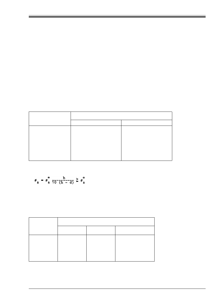
ENV 1992-1-1:1992
© BSI 12-1999
117
(2) Where at least the minimum reinforcement given by 4.4.2.2, is provided, the limitation of crack widths
to acceptable values and the avoidance of uncontrolled cracking between widely spaced bars may generally
be achieved by limiting bar spacings and/or bar diameters. Table 4.11 and Table 4.12 below are designed
to ensure that crack widths will not generally exceed 0.3 mm for reinforced concrete and 0.2 mm for
prestressed concrete. It should be noted, however, that larger cracks could occasionally occur but that this
should not be considered to be serious.
Crack widths will not generally be excessive provided that:
— for cracking caused dominantly by restraint, the bar sizes given in Table 4.11 are not exceeded where
the steel stress is the value obtained immediately after cracking [i.e. B
s
in Equation (4.78) in 4.4.2.2(3)]
and
— for cracks caused dominantly by loading, either the provisions of Table 4.11 or the provisions of
Table 4.12 are complied with.
For prestressed concrete sections, the stresses in the reinforcement should be calculated regarding the
prestress as an external force without allowing for the stress increase in the tendons due to loading.
Table 4.11 — Maximum bar diameters for high bond bars
For reinforced concrete the maximum bar diameter may be modified as follows:
Ì
s
= Ì f
ctm
/(2.5) h/[10 (h – d)] T Ì (f
ctm
/2.5) for restraint cracking
Table 4.12 — Maximum bar spacings for high bond bars
(3) In Table 4.11 and Table 4.12 the steel stresses used should be evaluated for reinforced concrete on the
basis of the quasi-permanent loads and for prestressed concrete on the basis of the frequent loads and the
relevant estimated value of prestress.
Steel stress
(MPa)
Maximum bar size
(mm)
Reinforced sections
Prestressed sections
160
200
240
280
320
360
400
450
32
25
20
16
12
10
8
6
25
16
12
8
6
5
4
for load induced cracking
where:
Ì
s
is the adjusted maximum bar diameter
Ì
is the maximum bar size given in the Table 4.11
h
is the overall depth of the section
Steel stress
(MPa)
Maximum bar spacing
(mm)
Pure flexure
Pure tension
Prestressed sections
(bending)
160
200
240
280
320
360
300
250
200
150
100
50
200
150
125
75
—
—
200
150
100
50
—
—
*
s
*
s
*
s
Licensed copy:Heriot Watt University, 20/04/2004, Uncontrolled Copy, © BSI

ENV 1992-1-1:1992
118
© BSI 12-1999
In Table 4.11, if the stresses arise dominantly from restraint then a steel stress equal to B
s
in
Equation (4.78) should be used.
(4) Beams with a total depth of 1.0 m or more where the main reinforcement is concentrated in only a small
proportion of the depth should be provided with additional skin reinforcement to control cracking on the
side faces of the beam. This reinforcement should be evenly distributed between the level of the tension
steel and the neutral axis and should be located within the stirrups. The area of the skin reinforcement
should not be less than the amount obtained from 4.4.2.2(3) taking k as 0.5 and B
s
as f
yk
. The spacing and
size of suitable bars may be obtained from Table 4.11 or Table 4.12 assuming pure tension and a steel
stress of half the value assessed for the main tension reinforcement.
(5) Cracking due to tangential action effects may be assumed to be adequately controlled provided the
spacings of stirrups given in Table 4.13 are satisfied. No check is required in members which do not require
shear reinforcement (i.e. where V
cd
> V
Sd
), or where 3V
cd
> V
Sd
, as the member will not have developed
shear cracks under service loads.
Table 4.13 — Spacing of stirrups in beams for
crack control
In Table 4.13, V
Sd
is the design shear force at the ultimate limit state and V
cd
may be taken as equal to
V
Rd1
, given by Equation (4.18) in 4.3.2.3, while @
w
is the shear steel ratio as defined in Equation (4.79)
below:
(6) It should be noted that there are particular risks of large cracks occurring at sections where there are
sudden changes of stress, e.g.
— at changes of section
— near concentrated loads
— sections where bars are curtailed
— areas of high bond stress, particularly at the ends of laps
Care should be taken at such sections to minimise the stress changes wherever possible. However, the rules
for crack control given above will normally ensure adequate control at these points provided the rules for
detailing reinforcement given in chapter 5 are complied with.
4.4.2.4
Calculation of crack widths
P(1) The design crack width may be obtained from the relation:
(N/mm
2
)
Stirrup spacing
(mm)
r 50
75
100
150
200
300
200
150
100
50
@
w
= A
sw
/(s b
w
sin !)
(4.79)
where:
@
w
is the shear reinforcement ratio
A
sw
is the area of shear reinforcement within a length s
s
is the spacing of the shear reinforcement
b
w
is the breadth of the web or minimum width of the member over the effective depth
!
is the angle between the shear reinforcement and the main steel (i.e. for vertical
stirrups ! = 90° and sin ! = 1)
w
k
= " s
rm
(
sm
(4.80)
where
w
k
is the design crack width
V
Sd
3V
cd
–
(
)
@
w
b
w
d
---------------------------------
Licensed copy:Heriot Watt University, 20/04/2004, Uncontrolled Copy, © BSI
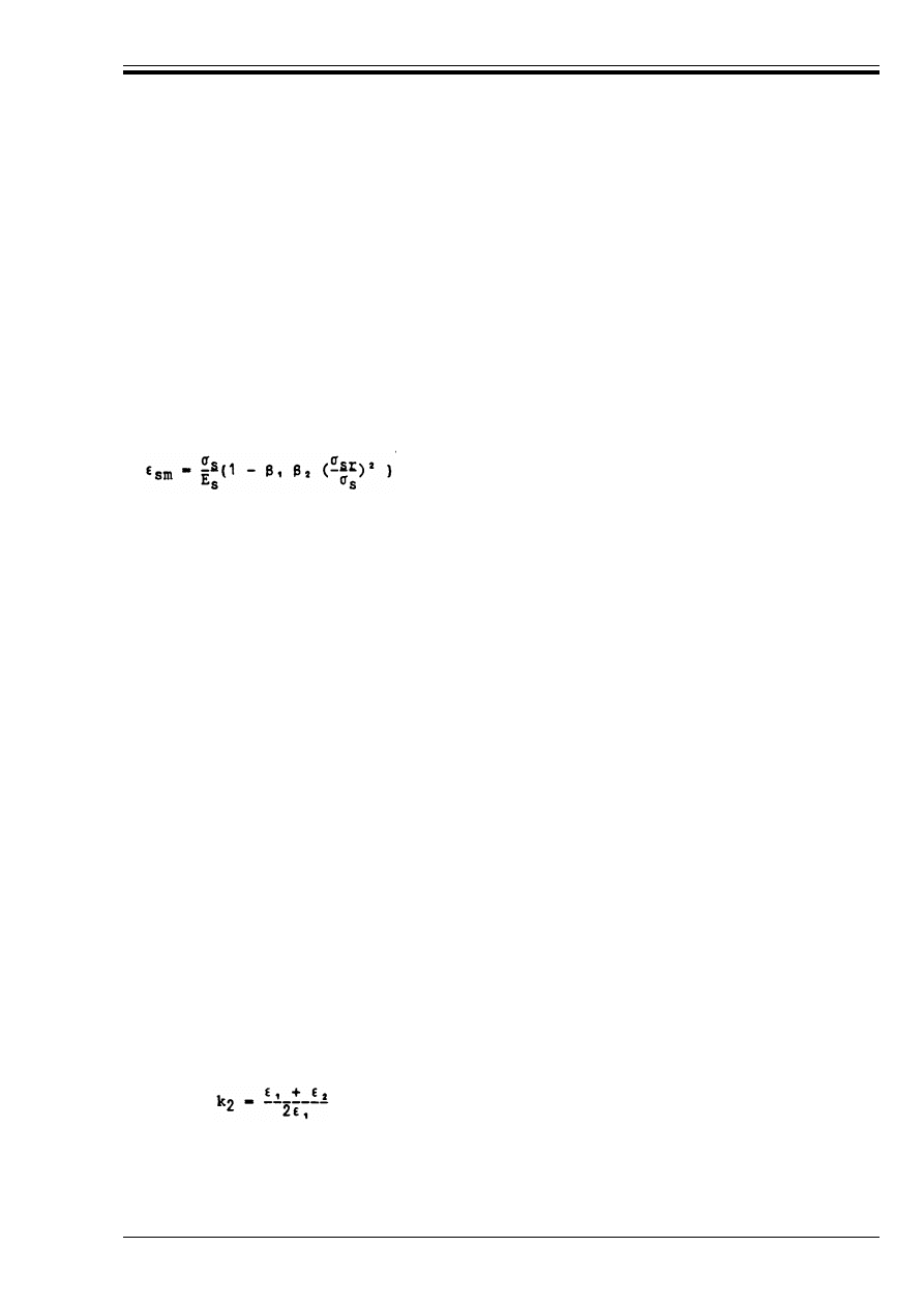
ENV 1992-1-1:1992
© BSI 12-1999
119
(2) The values of " in Equation (4.80) may be taken as:
where:
(3) The average final crack spacing for members subjected dominantly to flexure or tension can be
calculated from the equation:
where
s
rm
is the average final crack spacing
(
sm
is the mean strain allowing under the relevant combination of loads for the
effects of tension stiffening, shrinkage, etc.
"
is a coefficient relating the average crack width to the design value
"
= 1.7 for load induced cracking and for restraint cracking in sections with a minimum dimension
in excess of 800 mm.
= 1.3 for restraint cracking in sections with a minimum dimension depth, breadth or thickness,
whichever is the lesser) of 300 mm or less.
values for intermediate section sizes may be interpolated.
(
sm
may be calculated from the relation:
(4.81)
B
s
is the stress in the tension reinforcement calculated on the basis of a cracked section
B
sr
is the stress in the tension reinforcement calculated on the basis of a cracked section under the
loading conditions causing first cracking.
"
1
is a coefficient which takes account of the bond properties of the bars
= 1.0 for high bond bars
= 0.5 for plain bars
"
2
is a coefficient which takes account of the duration of the loading or of repeated loading
= 1.0 for a single, short term loading
= 0.5 for a sustained load or for many cycles of repeated loading.
For members subjected only to intrinsic imposed deformations, B
s
may be taken as equal to B
sr
s
rm
= 50 + 0.25 k
1
k
2
Ì/@
r
(4.82)
Ì
is the bar size in mm. Where a mixture of bar sizes is used in a section, an average bar size may
be used.
k
1
is a coefficient which takes account of the bond properties of the bars; k
1
= 0.8 for high bond bars
and 1.6 for plain bars. In the case of imposed deformations, k
1
should be replaced by k
1
· k, with
k being in accordance with 4.4.2.2(3).
k
2
is a coefficient which takes account of the form of the strain distribution
= 0.5 for bending and 1.0 for pure tension
For cases of eccentric tension or for local areas, intermediate values of k
2
should be used which
can be calculated from the relation:
where (
1
is the greater and (
2
the lesser tensile strain at the boundaries of the section considered,
assessed on the basis of a cracked section.
@
r
is the effective reinforcement ratio, A
s
/A
c.eff
, where A
s
is the area of reinforcement contained
within the effective tension area, A
c.eff
.
Licensed copy:Heriot Watt University, 20/04/2004, Uncontrolled Copy, © BSI
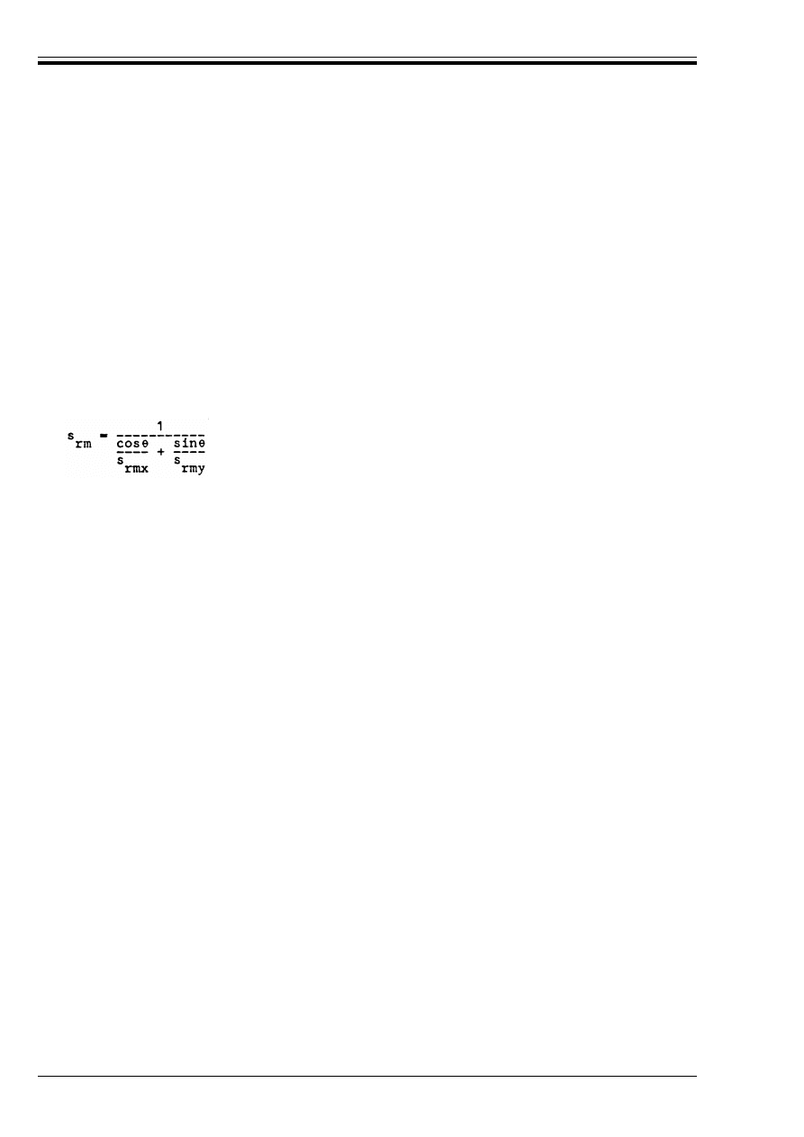
ENV 1992-1-1:1992
120
© BSI 12-1999
The effective tension area is generally the area of concrete surrounding the tension reinforcement of depth
equal to 2.5 times the distance from the tension face of the section to the centroid of the reinforcement.
(See Figure 4.33). For slabs or for prestressed members where the depth of the tension zone may be small,
the height of the effective area should not be taken as greater than (h – x)/3.
The resulting value of s
rm
will be in mm.
(4) Prestressing tendons may be taken into account in the calculation of crack spacings within a 300 mm
square area surrounding the tendon provided allowance is made for bond behaviour of the tendons.
Appropriate values for k
1
for particular tendons should be obtained from tests but, in the absence of better
information, a value of 2.0 may be taken. Where a mixture of tendons and ordinary reinforcement are
present, k
1
Ì in Equation (4.82) may be replaced by C k
1
Ì/n where C k
1
Ì is the sum of the diameter of all
bars and tendons within the area considered, each multiplied by its appropriate bond coefficient, and n is
the total number of bars and tendons.
(5) Where cracks form at a significant angle (> 15°) to the direction of the reinforcement in members
reinforced in two orthogonal directions then the crack spacing may be calculated from Equation (4.83)
below.
where
(6) Where the crack widths are to be calculated in design situations where tensile stresses arise from a
combination of restrained imposed deformations and loading, the formulae in this section may be used but
the strain due to loading, calculated on the basis of a cracked section, should be increased by that
resulting from imposed deformations.
(7) The methods given in this section calculate design crack widths in a region close to the bonded
reinforcement (i.e. within the effective tension area). Outside this region, larger cracks may occur.
(8) In cases where bonded reinforcement is not provided in the region where cracking is to be checked, an
upper bound to the crack width may be established for situations where the forces and moments in the
section ensure that parts of the section remain in compression. In such cases the average crack spacing
may be assumed to be equal to the height of the cracks. Examples of situations where this may be applied
are:
— Flexural members with very wide bar spacings. In this case crack widths may be calculated on the
assumption that s
rm
= (h – x) where h is the overall depth of the member and x is the neutral axis depth.
— Walls subjected to early thermal contraction where the bottom of the wall is restrained by a previously
cast base. In this case, s
rm
may be assumed to be equal to the height of the wall.
(4.83)
F is the angle between the reinforcement in the x direction and the direction of the principal tensile
stress.
s
rmx
and s
rmy
are the spacings calculated in the x and y directions respectively using Equation (4.82).
Licensed copy:Heriot Watt University, 20/04/2004, Uncontrolled Copy, © BSI
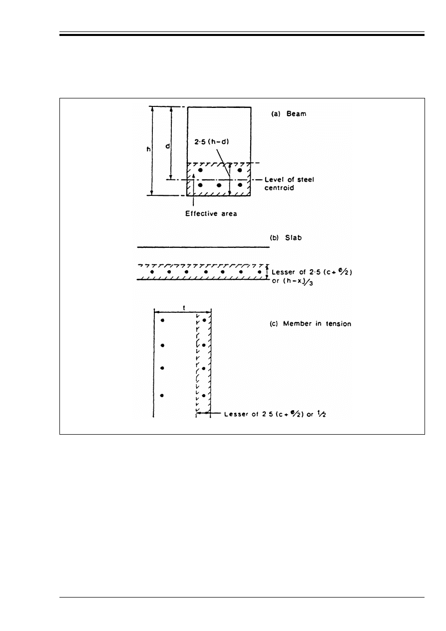
ENV 1992-1-1:1992
© BSI 12-1999
121
4.4.3 Limit states of deformation
4.4.3.1
Basic considerations
P(1) The deformation of a member or structure should not be such that it adversely affects its proper
functioning or appearance.
P(2) Appropriate limiting values of deflection taking into account the nature of the structure, of the
finishes, partitions and fixings and upon the function of the structure should be agreed with the client.
(3) Deformations should not exceed those which can be accommodated by other connected elements such
as partitions, glazing, cladding, services or finishes. In some cases limitation may be required to ensure
the proper functioning of machinery or apparatus supported by the structure or to avoid ponding on flat
roofs. Vibration may also require limitation as it can cause discomfort or alarm to users of a building and,
in extreme cases, structural damage.
(4) The limiting deflections given in (5) and (6) below are derived from ISO 4356 and should ensure
generally satisfactory performance for buildings such as dwellings, offices, public buildings or factories.
Care should be taken to ensure that there are no special circumstances which would render them
inappropriate for the structure considered. Further information on problems resulting from deflections
and limiting values can be obtained from ISO 4356.
Figure 4.33 — Effective area (typical cases)
Licensed copy:Heriot Watt University, 20/04/2004, Uncontrolled Copy, © BSI

ENV 1992-1-1:1992
122
© BSI 12-1999
(5) The appearance and general utility of the structure may be impaired when the calculated sag of a
beam, slab or cantilever subjected to the quasi-permanent loads exceeds |span/250|. The sag is assessed
relative to the supports. Precamber may be used to compensate for some or all of the deflection but any
upward deflection incorporated in the formwork should not generally exceed |span/250|.
(6) Deflections may cause damage to partitions, to members attached to, or in contact with the member
considered, and to fixtures or finishes, if the calculated deflection occurring after construction of the
elements which could suffer damage is excessive. An appropriate limit will depend upon the nature of the
elements which could suffer damage but, as a guide, a limit of |span/500| is considered reasonable for
most circumstances. This limit may be relaxed in cases where the elements which might suffer damage
have been designed to accommodate greater deflections or where they are known to be capable of
withstanding greater deformations without damage.
4.4.3.2
Cases where calculations may be omitted
P(1) Generally, it is not necessary to calculate the deflections explicitly as simple rules, such as limits to
span/depth ratio may be formulated which will be adequate for avoiding deflection problems in normal
circumstances. More rigorous checks are necessary for members which lie outside such limits or where
deflection limits other than those implicit in simplified methods are appropriate.
(2) Provided reinforced concrete beams or slabs in buildings are dimensioned so that they comply with the
limits of span to depth given in this clause, their deflections should not normally exceed the limits set out
in 4.4.3.1(5) and (6). The limiting span/depth ratio is obtained by taking a basic ratio from
Table 4.14 and multiplying this by correction factors to allow for the type of reinforcement used and other
variables. No allowance has been made for any precamber in the derivation of these tables.
(3) The value obtained from Table 4.14 should be reduced in the following cases:
— For flanged sections where the ratio of the flange breadth to the rib breadth exceeds 3, the values
should be multiplied by 0.8.
— For spans exceeding 7 m, other than flat slabs, supporting partitions liable to be damaged by excessive
deflections, the value should be multiplied by 7/l
eff
(l
eff
in metres).
— For flat slabs where the greater span, l
eff
, exceeds 8.5 m, the values should be multiplied
by 8.5/l
eff
(l
eff
in metres).
(4) The values in Table 4.14 have been derived on the assumption that the steel stress, under the design
service load at a cracked section at the mid-span of a beam or slab or at the support of a cantilever,
is 250 N/mm
2
. (Corresponding roughly to f
yk
= 400 N/mm
2
). Where other stress levels are used, the values
in Table 4.14 should be multiplied by 250/B
s
where B
s
is the stress at the section given above under the
frequent combination of loads. It will normally be conservative to assume
that 250/B
s
= 400/(f
yk
· A
s.req
/A
s.prov
)
(5) In interpreting Table 4.14 the following additional points may be noted.
a) the values given have been chosen to be generally conservative and calculation may frequently show
that thinner members are possible.
b) members where the concrete is lightly stressed are those where @ < 0.5 % (@ = A
s
/bd). It may normally
be assumed that slabs are lightly stressed.
c) If the reinforcement ratio is known, values intermediate between those for highly stressed and lightly
stressed cases may be obtained by interpolation, assuming the “lightly stressed” values to correspond to
@ = 0.5 % and the “highly stressed” values to correspond to @ = 1.5 %.
d) for 2-way spanning slabs, the check should be carried out on the basis of the shorter span. For flat
slabs the longer span should be taken.
e) the limits given for flat slabs correspond to a less severe limitation than a mid span deflection
|span/250| relative to the columns. Experience has shown this to be satisfactory.
where
A
s.prov
is the area of steel provided at the defined section.
A
s.req
is the area of steel required at the section to give the required design ultimate
moment of resistance.
Licensed copy:Heriot Watt University, 20/04/2004, Uncontrolled Copy, © BSI

ENV 1992-1-1:1992
© BSI 12-1999
123
Table 4.14 — Basic ratios of span/effective depth for reinforced concrete members
without axial compression
4.4.3.3
Checking deflections by calculation
P(1) Where a calculation is deemed necessary, the deformations shall be calculated under load conditions
which are appropriate to the purpose of the check.
P(2) The calculation method adopted shall represent the true behaviour of the structure under relevant
actions to an accuracy appropriate to the objectives of the calculation.
(3) Appendix 4 gives further information on the calculation of deflections.
5 Detailing provisions
5.0 Notation
(See also 1.6 and 1.7)
Structural System
Concrete highly
stressed
Concrete lightly
stressed
1.
Simply supported beam, one or two-way spanning simply
supported slab
18
25
2.
End span of continuous beam or one way continuous slab
or two-way spanning slab continuous over one long side
23
32
3.
Interior span of beam or one-way or two-way spanning
slab
25
35
4.
Slab supported on columns without beams (Flat slab)
(based on longer span) —
21
30
5.
Cantilever
7
10
A
cl
Maximum area corresponding geometrically to A
co
, and having the same centre of gravity
A
co
Loaded area (Figure 5.19)
A
ct,ext
Area of concrete external to stirrups (Figure 5.15)
A
s,min
Minimum area of longitudinal tensile reinforcement
A
s,prov
Area of steel provided
A
s,req
Area of steel required
A
s,surf
Area of surface reinforcement
A
st
Area of additional transverse reinforcement parallel to the lower face
A
sv
Area of additional transverse reinforcement perpendicular to the lower face
F
s
Force in the tensile longitudinal reinforcement at a critical section at the ULS
F
Rdu
Concentrated resistance force (Equation 5.22)
a
Horizontal clear distance between two parallel laps
a
1
Horizontal displacement of the envelop line of the tensile force (shift rule)
b
Lateral concrete cover in the plane of a lap
b
t
Mean width of a beam in tension zone
c
Minimum concrete cover
d
g
Largest nominal maximum aggregate size
f
bd
Design value for ultimate bond stress
l
b
Basic anchorage length for reinforcement
Licensed copy:Heriot Watt University, 20/04/2004, Uncontrolled Copy, © BSI

ENV 1992-1-1:1992
124
© BSI 12-1999
5.1 General
P(1) The rules given in this Chapter apply to all reinforcement, mesh and prestressing tendons, subjected
to predominantly static loading; they do not apply to:
— lightweight aggregate concrete
— dynamic loading.
(2) For lightweight aggregate concrete, supplementary rules are given in Part 1C.
(3) For structures subjected to fatigue loading, see Part 1E.
P(4) The requirements concerning minimum concrete cover shall be satisfied (4.1.3.3).
5.2 Steel for reinforced concrete
5.2.1 General detailing arrangements
5.2.1.1
Spacing of bars
P(1) The spacing of bars shall be such that the concrete can be placed and compacted satisfactorily and that
the development of adequate bond is assured.
(2) The maximum aggregate size, d
g
, should be chosen to permit adequate compaction of the concrete
round the bars.
(3) The clear distance (horizontal and vertical) between individual parallel bars or horizontal layers of
parallel bars should be not less than the |maximum bar diameter or 20 mm|. In addition
where d
g
> 32 mm, these distances should be not less than d
g
+ 5 mm.
(4) Where bars are positioned in separate horizontal layers, the bars in each layer should be located
vertically above each other and the space between the resulting columns of bars should permit the
passage of an internal vibrator.
(5) Lapped bars may touch one another within the lap length.
l
b,min
Minimum anchorage length
l
b,net
Required anchorage length
l
s
Necessary lap length (Figure 5.4)
l
s,min
Minimum lap length
n
Number of transverse bars along anchorage length
n
1
Number of layers with bars anchored at the same point
n
2
Number of bars anchored in each layer
n
b
Number of bars in a bundle
p
Mean transverse pressure (N/mm
2
) over the anchorage length
s
1
Spacing of longitudinal wires in a welded mesh fabric, or in surface reinforcement
s
max
Maximum longitudinal spacing of successive series of stirrups
s
t
Spacing of transverse wires in a welded mesh fabric or in surface reinforcement
u
k
Circumference of area A
k
(Figure 4.15)
!
Angle of the shear reinforcement with the longitudinal reinforcement (main steel)
!
a
A coefficient for determining the effectiveness of anchorages
!
1
Coefficients for effectiveness of laps
!
2
Coefficient for the calculation of the lap length of welded mesh fabrics
F
Angle between the concrete struts and the longitudinal axis
Licensed copy:Heriot Watt University, 20/04/2004, Uncontrolled Copy, © BSI
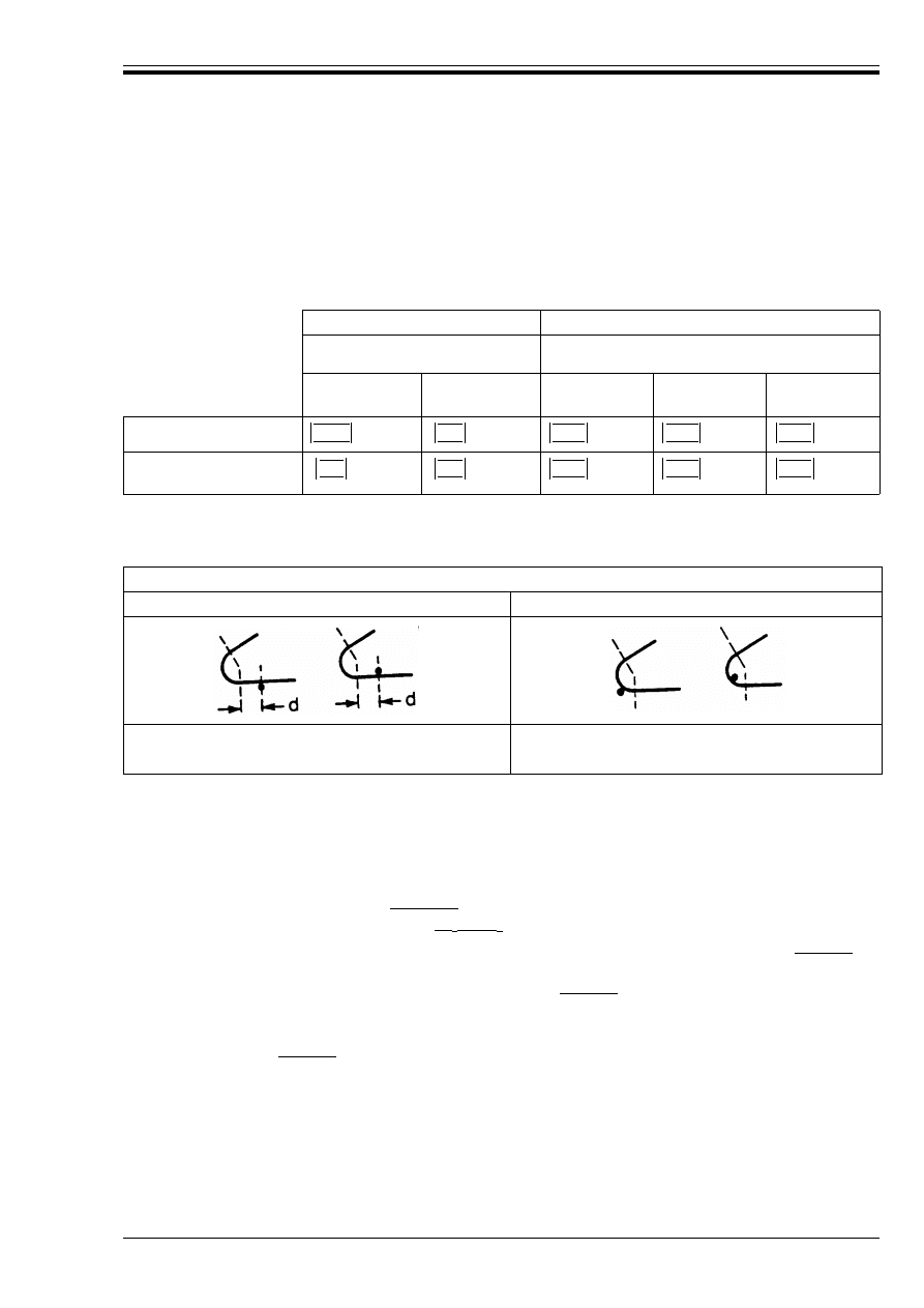
ENV 1992-1-1:1992
© BSI 12-1999
125
5.2.1.2
Permissible curvatures
P(1) The minimum diameter to which a bar is bent shall be such as to avoid crushing or splitting of the
concrete inside the bend of the bar, and to avoid bending cracks in the bar.
(2) For bars or wires, the minimum diameter of the mandrel used should be not less than the values given
in Table 5.1
Table 5.1 — Minimum diameters of mandrels
(3) For welded reinforcement and mesh bent after welding, the minimum diameters of mandrels are given
in Table 5.2.
Table 5.2 — Minimum diameters of mandrels for welded bent reinforcement
5.2.2 Bond
5.2.2.1
Bond conditions
P(1) The quality of the bond depends on the surface pattern of the bar, on the dimension of the member and
on the position and inclination of the reinforcement during concreting.
(2) For normal weight concrete, the bond conditions are considered to be good for:
a) all bars, with an inclination of |45° to 90°| to the horizontal, during concreting [Figure 5.1 a)];
b) all bars which have an inclination of |10° to 45°| to the horizontal during concreting and are:
— either placed in members whose depth in the direction of concreting does not exceed |250 mm|
[Figure 5.1 b)],
— or embedded in members with a depth greater than |250 mm| and when concreting is completed,
are:
• either in the lower half of the member [Figure 5.1 c)]
• or at least |300 mm| from its top surface [Figure 5.1 d)]
(3) All other conditions are considered poor.
Hooks, bends, loops (see Figure 5.2)
Bent-up bars or other curved bars
Bar diameter
Value of minimum concrete cover, perpendicular
to plane of curvature
Ì < 20 mm
Ì
T 20 mm
> 100 mm
and > 7 Ì
> 50 mm
and > 3 Ì
r 50 mm
and r 3 Ì
Plain bare S 220
High bond bars
S400, S500
Minimum diameter of the mandrel
Welds outside bends
Welds inside bends
d < 4 Ì: 20 Ì
20 Ì
d T 4 Ì: Table 5.1 applies
2.5 Ì
5 Ì
10 Ì
10 Ì
15 Ì
4 Ì
7 Ì
10 Ì
15 Ì
20 Ì
Licensed copy:Heriot Watt University, 20/04/2004, Uncontrolled Copy, © BSI
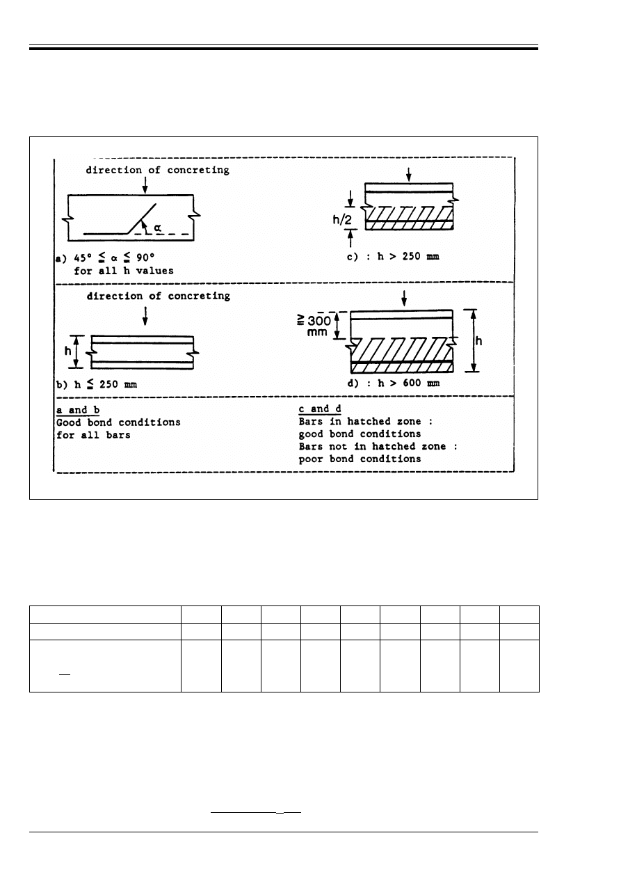
ENV 1992-1-1:1992
126
© BSI 12-1999
5.2.2.2
Ultimate bond stress
P(1) The ultimate bond stress shall be such that no significant relative displacement between the steel and
concrete occurs under service loads, and that there is an adequate safety margin against bond failure.
(2) In conditions of good bond, the design values for the ultimate bond stress f
bd
are given in Table 5.3. In
all other cases, the values in Table 5.3 should be multiplied by a coefficient 0.7.
Table 5.3 — Design values f
bd
(N/mm
2
) for good bond conditions (these values
incorporate a *
c
value equal to 1.5)
(3) In the case of transverse pressure p in N/mm
2
(transverse to the possible plane of splitting) the values
of Table 5.3 should be multiplied by |1/(1 – 0.04 p) d 1.4|, where p is the mean transverse pressure.
Figure 5.1 — Definition of bond conditions
f
ck
12
16
20
25
30
40
45
50
Plain bars
0.9
1.0
1.1
1.2
1.3
1.4
1.5
1.6
1.7
High bond bars
where
Ì
r |32| mm or welded mesh
fabrics made of ribbed wires
1.6
2.0
2.3
2.7
3.0
3.4
3.7
4.0
4.3
These values are derived from the following formulae: (with *
c
= 1.5)
— plain bars, f
bd
= (0.36ßf
ck
)/*
c
(5.1)
— high bond bars, f
bd
= (2.25f
ctk
0.05)/*c
(5.2)
where f
ck
and f
ctk
0.05 are as defined in Chapter 3.1.
Licensed copy:Heriot Watt University, 20/04/2004, Uncontrolled Copy, © BSI
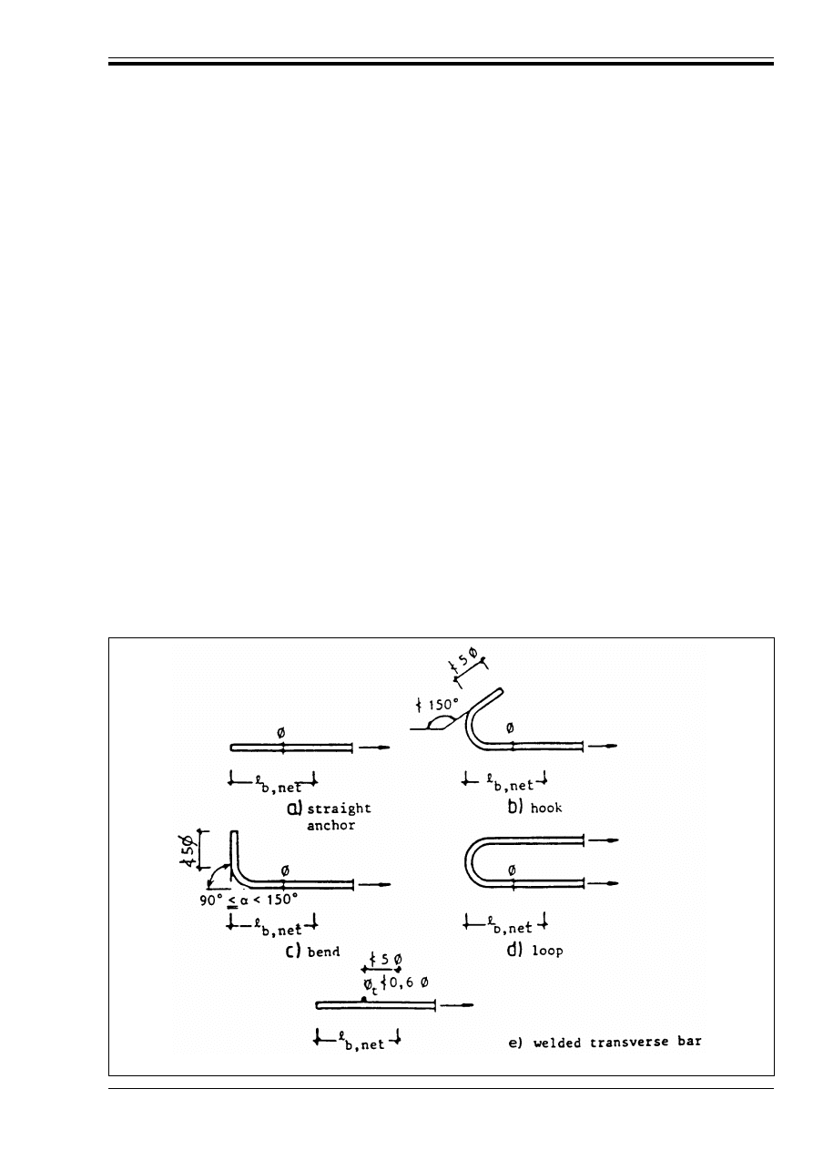
ENV 1992-1-1:1992
© BSI 12-1999
127
5.2.2.3
Basic anchorage length
P(1) The basic anchorage length is the straight length required for anchoring the force A
s.fyd
in a bar,
assuming constant bond stress equal to f
bd
; in setting the basic anchorage length, the type of the steel and
the bond properties of the bars shall be taken into consideration.
(2) The basic anchorage length required for the anchorage of a bar of diameter Ì is:
(3) For double bar welded fabrics the diameter Ì in Equation (5.3) should be replaced by the equivalent
diameter Ì
n
= Ìß2.
5.2.3 Anchorage
5.2.3.1
General
P(1) The reinforcing bars, wires or welded mesh fabrics shall be so anchored that the internal forces to
which they are subjected are transmitted to the concrete and that longitudinal cracking or spalling of the
concrete is avoided. If necessary transverse reinforcement shall be provided.
P(2) Where mechanical devices are used, their effectiveness shall be proven by tests and their capacity to
transmit the concentrated force at the anchorage shall be examined with special care.
5.2.3.2
Anchorage methods
(1) The usual methods of anchorage are shown in Figure 5.2.
(2) Straight anchorages or bends [Figure 5.2 a) or Figure 5.2 c)] should not be used to anchor smooth bars
of more than 8 mm diameter.
(3) Bends, hooks or loops are not recommended for use in compression except for plain bars which may be
subjected to tensile forces in the anchorage zones, for certain load cases.
(4) Spalling or splitting of the concrete may be prevented by complying with Table 5.1 and avoiding
concentrations of anchorages.
l
b
= (Ì/4) (f
yd
/f
bd
)
(5.3)
Values for f
bd
are given in Table 5.3.
Figure 5.2 — Required anchorage length
Licensed copy:Heriot Watt University, 20/04/2004, Uncontrolled Copy, © BSI
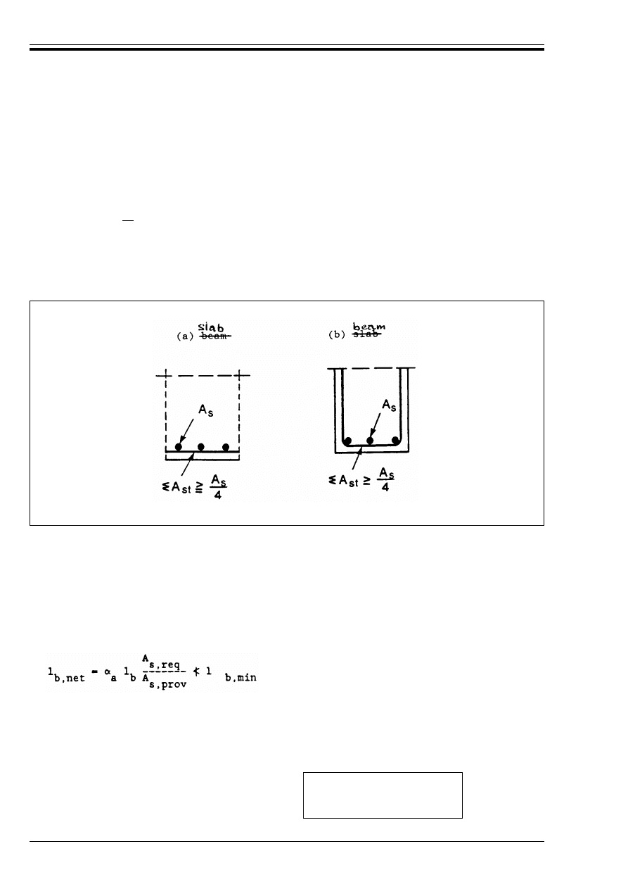
ENV 1992-1-1:1992
128
© BSI 12-1999
5.2.3.3
Transverse reinforcement parallel to the concrete surface
(1) In beams transverse reinforcement should be provided:
— for anchorages in tension, if there is no transverse compression due to the support reaction (as is the
case for indirect supports, for example).
— for all anchorages in compression.
(2) The minimum total area of the transverse reinforcement (legs parallel to the layer of the longitudinal
reinforcement) is |25| percent of the area of one anchored bar (Figure 5.3).
(3) The transverse reinforcement should be evenly distributed along the anchorage length. At least one bar
should be placed in the region of the hook, bend or loop of curved bar anchorages.
(4) For bars in compression, the transverse reinforcement should surround the bars, being concentrated at
the end of the anchorage, and extend beyond it to a distance of at least 4 times the diameter of the anchored
bar [see Figure 5.5 b)].
5.2.3.4
Required anchorage length
5.2.3.4.1 Bars and wires
(1) The required anchorage length l
b,net
may be calculated from:
CA
st
= n.A
st
where:
n
= number of bars along anchorage length
A
st
= area of one bar of the transverse reinforcement
Figure 5.3 — Transverse reinforcement in the region of anchored bars
(5.4)
where (see Figure 5.2):
l
b
is given by Equation (5.3), see 5.2.2.3(2)
A
s,req
and A
s,prov
respectively denote the area of reinforcement required by design —
and actually provided
l
b,min
denotes the minimum anchorage length:
— for anchorages in tension
l
b,min
= 0.3 l
b
(@ 10 Ì )
(or)
(5.5)
— for anchorages in compression
l
b,min
= 0.6 l
b
(@ 100 mm)
(5.6)
Licensed copy:Heriot Watt University, 20/04/2004, Uncontrolled Copy, © BSI
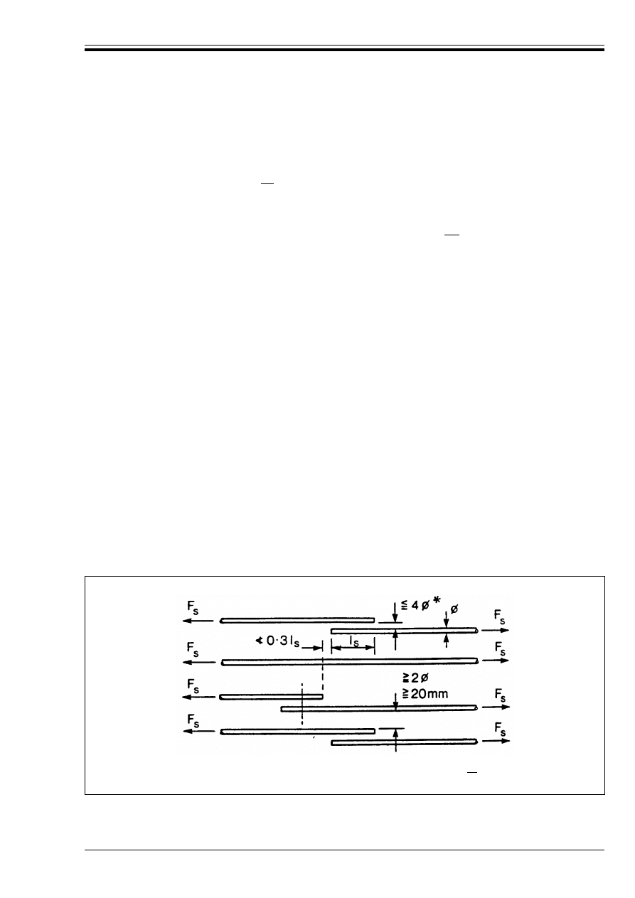
ENV 1992-1-1:1992
© BSI 12-1999
129
5.2.3.4.2 Welded meshes made of high bond wires
(1) Equation (5.4) may be applied
(2) If welded transverse bars are present in the anchorage, a coefficient |0.7| should be applied to the
values given by Equation (5.4).
5.2.3.4.3 Welded meshes made of smooth wires
(1) These may be used, subject to relevant Standards.
5.2.3.5
Anchorage by mechanical devices
P(1) The suitability of mechanical anchorage devices should be demonstrated by an Agrément certificate.
(2) For the transmission of the concentrated anchorage forces to the concrete, see 5.4.8.1
5.2.4 Splices
P(1) The detailing of splices between bars shall be such that:
— the transmission of the forces from one bar to the next is assured;
— spalling of the concrete in the neighbourhood of the joints does not occur;
— the width of cracks at the end of the splice does not significantly exceed the values given in
Section 4.4.2.1.
5.2.4.1
Lap splices for bars or wires
5.2.4.1.1 Arrangement of lapped joints
(1) As far as possible:
— laps between bars should be staggered and should not be located in areas of high stress,
(see also Section 2.5.3, Analysis).
— laps at any one section should be arranged symmetrically and parallel to the outer face of the member,
(2) Clauses 5.2.3.2(1) to (4) are also applicable to lap splices.
(3) The clear space between the two lapped bars in a joint should comply with the values indicated in
Figure 5.4.
!
a
is a coefficient which takes the following values:
!
a
= 1
for straight bars
!
a
= 0.7 for curved bars in tension (see Figure 5.2) if the concrete cover perpendicular to the plane
of curvature is at least |3Ì| in the region of the hook, bend or loop.
* otherwise the lap length shall be increased by the amount by which the clear space exceeds |4¿|.
Figure 5.4 — Adjacent laps
Licensed copy:Heriot Watt University, 20/04/2004, Uncontrolled Copy, © BSI
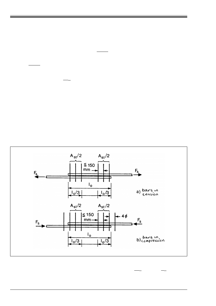
ENV 1992-1-1:1992
130
© BSI 12-1999
5.2.4.1.2 Transverse reinforcement
(1) If the diameter Ì of the lapped bars is less than |16 mm|, or if the percentage of lapped bars in any one
section is less than 20 %, then the minimum transverse reinforcement provided for other reasons (e.g.
shear reinforcement, distribution bars) is considered as sufficient.
(2) If Ì T |16 mm|, then the transverse reinforcement should:
— have a total area (sum of all legs parallel to the layer of the spliced reinforcement, see Figure 5.5,) of
not less than the area A
s
of one spliced bar (CA
st
T 1.0 A
s
)
— be formed as links if a r |10 Ì| (see Figure 5.6) and be straight in other cases
— the transverse reinforcement should be placed between the longitudinal reinforcement and the
concrete surface.
(3) For the distribution of the transverse reinforcement, 5.2.3.3(3) and (4) apply.
5.2.4.1.3 Lap length
(1) The necessary lap length is:
The coefficient !
1
takes the following values:
!
1
= 1 for lap lengths of bars in compression and of lap lengths in tension where less than 30 % of the
bars in the section are lapped and, according to Figure 5.6, where a @ |10 Ì| and b @ |5 Ì|.
l
s
= l
b,net
· !
1
@ l
s,min
(5.7)
with:
l
b,net
according to Equation (5.4)
l
s,min
@ 0.3 · !
a
.!
1
.l
b
@ 15 Ì @ 200 mm
(5.8)
Values of !
a
are given in 5.2.3.4.1.
Figure 5.5 — Transverse reinforcement for lapped splices
Licensed copy:Heriot Watt University, 20/04/2004, Uncontrolled Copy, © BSI
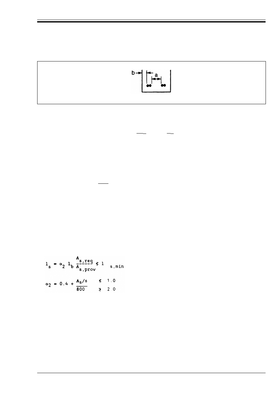
ENV 1992-1-1:1992
© BSI 12-1999
131
5.2.4.2
Laps for welded mesh fabrics made of high bond wires
5.2.4.2.1 Laps of the main reinforcement
(1) The following rules relate only to the most common case where laps are made by layering of the sheets.
Rules for laps with intermeshed sheets are given separately from this Code.
(2) The laps should generally be situated in zones where the effects of actions under the rare combinations
of loads are not more than |80 %| of the design strength of the section.
(3) Where condition (2) is not fulfilled, the effective depth of the steel taken into account in the calculations
in accordance with Section 4.3.1 should apply to the layer furthest from the tension face.
(4) The permissible percentage of the main reinforcement which may be lapped in any one section, referred
to the total steel cross section is:
(5) The lap length is defined by:
(6) Additional transverse reinforcement is not necessary in the zone of lapping.
Figure 5.6 — Evaluation of !
1
[see 5.2.4.1.3(1)]
!
1
= 1.4 for tension lap lengths where
either
i) 30 % or more of the bars at a section are lapped
or
ii) according to Figure 5.6, if a < |10 Ì| or b < |5 Ì|, but not both.
!
1
= 2 for tension lap lengths if both i) and ii) above apply simultaneously.
— 100 % if the specific cross sectional area of the mesh, denoted by A
s
/s, is such that
A
s
/s r 1 200 mm
2
/m
— 60 % if A
s
/s > 1 200 mm
2
/m and if this wire mesh is an interior mesh.
The joints of the multiple layers should be staggered at 1.3 l
s
[l
s
from Equation (5.9)].
(5.9)
l
b
from Equation (5.3) using f
bd
for high bond bars
A
s,req
and A
s,prov
are as defined in 5.2.3.4.1(1)
A
s
/s
in mm
2
/m
l
s,min
= 0.3 !
2
l
b
(@ 200 mm
(@ s
t
where
s
t
denotes the spacing of transverse welded wires.
Licensed copy:Heriot Watt University, 20/04/2004, Uncontrolled Copy, © BSI
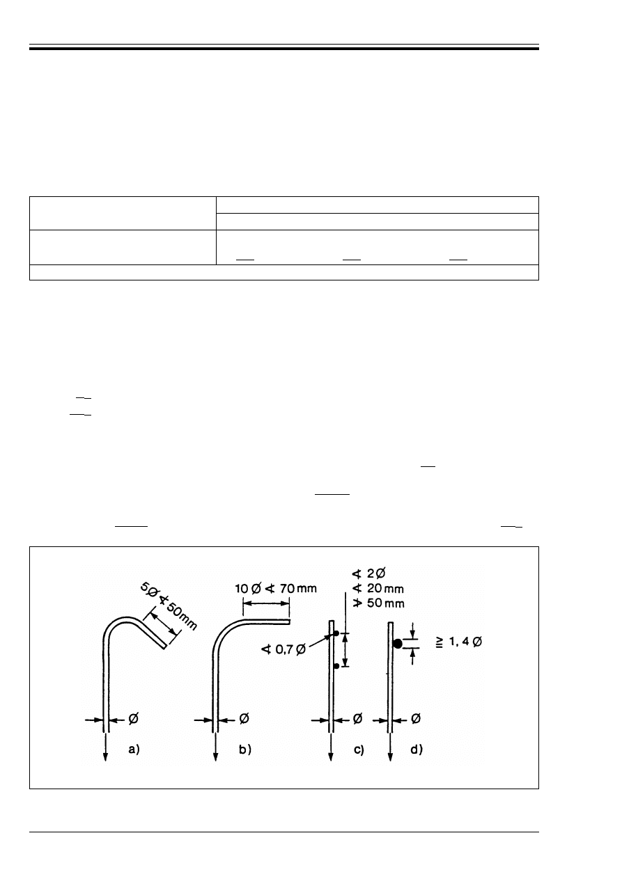
ENV 1992-1-1:1992
132
© BSI 12-1999
5.2.4.2.2 Laps of the transverse distribution reinforcement
(1) All transverse reinforcement may be lapped at the same location.
The minimum values of the lap length l
s
are given in Table 5.4; at least two transverse bars should be
within the lap length (one mesh).
Table 5.4 — Recommended lap lengths in the transverse direction
5.2.5 Anchorage of links and shear reinforcement
P(1) The anchorage of links and shear reinforcement shall normally be effected by means of hooks, or by
welded transverse reinforcement. High bond bars or wires can also be anchored by bends. A bar should be
provided inside a hook or bend.
(2) For the permissible curvature of hooks and bends, see 5.2.1.2(2).
(3) The anchorage as a whole is considered to be satisfactory:
— where the curve of a hook or bend is extended by a straight length which is not less than:
— where there are near the end of a straight bar:
• either two welded transverse bars [see Figure 5.7 c)],
• or a single welded transverse bar, the diameter of which is not less than |1.4| times the diameter
of the bar [see Figure 5.7 d)].
5.2.6 Additional rules for high bond bars exceeding |32 mm| in diameter
5.2.6.1
Construction details
P(1) Bars of Ì > |32 mm| shall be used only in elements whose minimum depth is not less than |15 Ì|.
P(2) When large bars are used, adequate crack control shall be ensured either by using surface
reinforcement (see 5.4.2.4) or by calculation (see 4.4.2).
Diameter of bars
(mm)
Ì
r 6
6 < Ì r 8.5
8.5 < Ì r 12
@ s
1
@ s
1
@ s
1
High bond wires
@ |150| mm
@ |250| mm
@ |350| mm
s
1
= spacing of longitudinal wires
• |5 Ì| or 50 mm
if it is a continuation of an arc of 135° or more [Figure 5.7 a)];
• |10 Ì| or 70 mm
if it is a continuation of an arc of 90° [Figure 5.7 b)].
Figure 5.7 — Anchorage of links
Licensed copy:Heriot Watt University, 20/04/2004, Uncontrolled Copy, © BSI
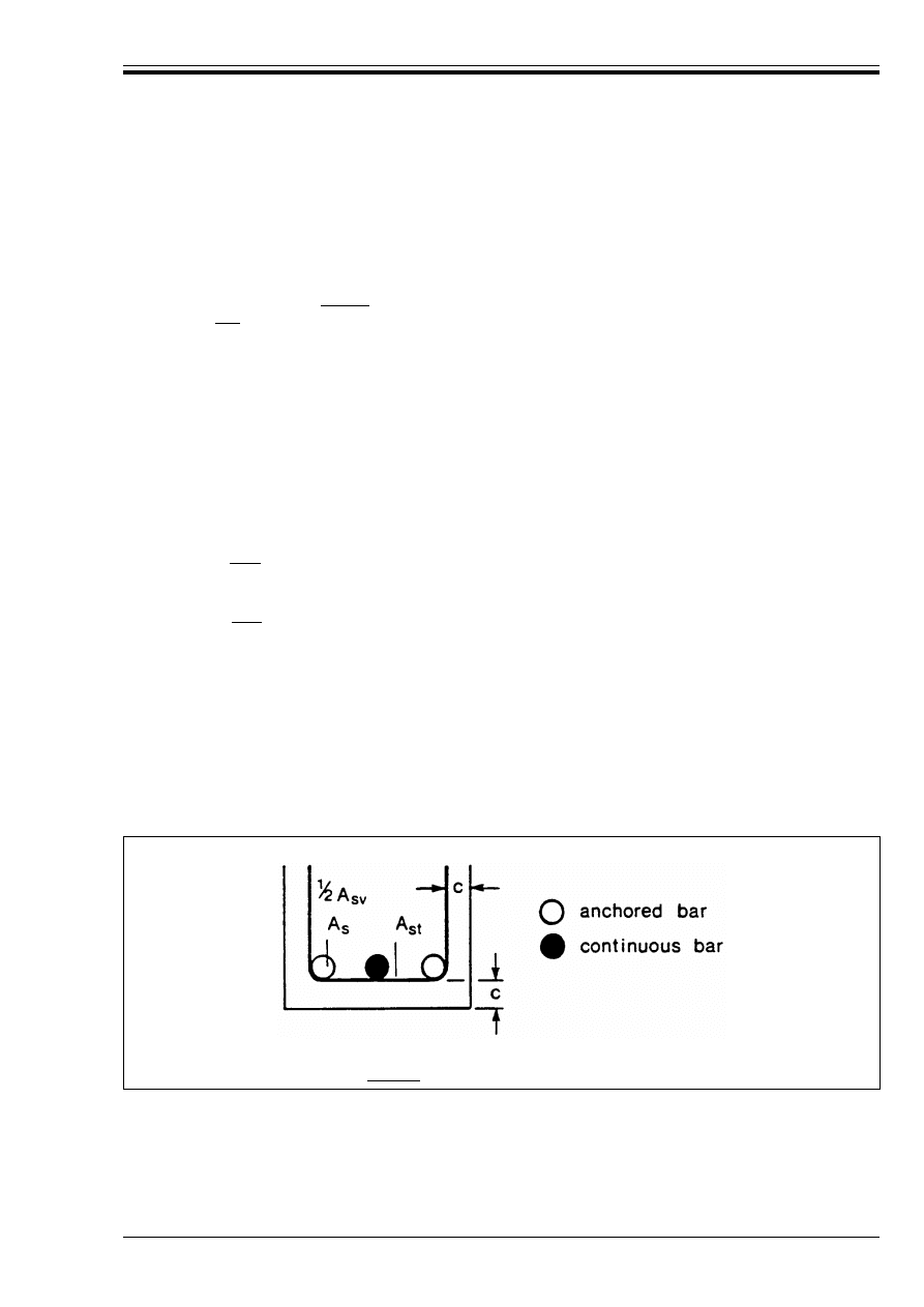
ENV 1992-1-1:1992
© BSI 12-1999
133
(3) The minimum concrete cover should be c T Ì.
(4) The clear distance (horizontal and vertical) between individual parallel bars or horizontal layers of
parallel bars should be not less than the maximum bar diameter or d
g
+ 5 mm where d
g
is the maximum
aggregate size.
5.2.6.2
Bond
P(1) For bar diameter Ì < |32 mm| the values f
bd
in Table 5.3 (see 5.2.2.2) should be multiplied by the
coefficient (|132| – Ì)/100. (Ì in mm).
5.2.6.3
Anchorages and joints
P(1) Large diameter bars shall be anchored as straight bars or by means of mechanical devices. They shall
not be anchored in tension zones.
P(2) Lapped Joints shall not be used either for tension or compression bars.
(3) The rules given below are complementary to those given in clauses 5.2.3.
(4) In the absence of transverse compression, additional transverse reinforcement is needed in the
anchorage zone in beams and slabs, additional to the shear reinforcement.
(5) For straight anchorages (see Figure 5.8 for the notation used) the additional reinforcement
in (4) above should not be less than the following:
— in the direction parallel to the lower face:
— in the direction perpendicular to the lower face:
where:
(6) The additional transverse reinforcement should be uniformly distributed in the anchorage zone with
spacings which should not exceed approximately five times the diameter of the longitudinal
reinforcement.
(7) For surface reinforcement, 5.4.2.4 applies, but the area of surface reinforcement should not be less
than 0.01 A
ct,ext
in the direction perpendicular to large diameter bars, and 0.02 A
ct,ext
parallel to those
bars (notations, see Figure 5.15).
A
st
= n
1
|0.25| A
s
(5.10)
A
sv
= n
2
|0.25| A
s
(5.11)
A
s
denotes the cross sectional area of an anchored bar,
n
1
is the number of layers with bars anchored at the same point in the member,
n
2
is the number of bars anchored in each layer.
Figure 5.8 — Additional reinforcement in an anchorage zone where the bar diameter is
greater than |32 mm| and there is no transverse compression
Licensed copy:Heriot Watt University, 20/04/2004, Uncontrolled Copy, © BSI

ENV 1992-1-1:1992
134
© BSI 12-1999
5.2.7 Bundled high bond bars
5.2.7.1
General
P(1) Unless otherwise stated, the rules for individual bars also apply for bundles of bars. In a bundle, all
the bars shall be of the same diameter and characteristics (type and grade).
(2) In design, the bundle is replaced by a notional bar having the same sectional area and the same centre
of gravity as the bundle.
The “equivalent diameter” Ì
n
of this bar is such that:
(3) For a bundle, 5.2.1.1(2) applies, while using the equivalent diameter Ì
n
, but measuring the clear
distance from the actual external contour of the bundle of bars. The concrete cover measured from the
actual external contour of the bundles should be c > Ì
n
.
5.2.7.2
Anchorage and joints
P(1) Anchorage or lapping of a bundle of bars shall be achieved by anchorage or lapping of the individual
bars. Only straight bar anchorages are permitted; they shall be staggered.
(2) For bundles of 2,3 or 4 bars, the staggering distance of the anchorages should be | 1.2, 1.3 and 1.4|
times the anchorage length of the individual bars respectively.
(3) The bars should be lapped one by one. In any case not more than 4 bars should be present in any one
section. The lapped joints of the individual bars should be staggered as given in (2) above.
5.3 Prestressing units
5.3.1 Arrangement of the prestressing units
P(1) In the case of pre-tensioning, the tendons shall be spaced apart.
P(2) In the case of post-tensioned members, bundled ducts are not normally permitted.
(3) A pair of ducts, placed vertically one above the other, may be used if adequate precautions are taken
for tensioning and grouting. Particular care is necessary if the tendons are doubly curved.
5.3.2 Concrete cover
P(1) The concrete cover between the inner surface of the formwork and either a pre-tensioned tendon or a
duct shall be fixed with due regard to the size of the tendons or of the duct. Minimum covers shall be in
accordance with 4.1.3.3.
5.3.3 Horizontal and vertical spacing
P(1) The spacing of ducts or of pre-tensioned tendons shall be such as to ensure that placing and compacting
of the concrete can be carried out satisfactorily and that good bond can be attained between the concrete
and the tendons.
5.3.3.1
Pre-tensioning
(1) The minimum clear horizontal and vertical spacing of individual tendons is given in Figure 5.9.
Ì
n
= Ìßnb 8 55 mm
(5.12)
where n
b
is the number of bars in the bundle, which is limited to:
n
b
r 4 for vertical bars in compression and for bars in a lapped joint,
n
b
r 3 for all other cases.
Licensed copy:Heriot Watt University, 20/04/2004, Uncontrolled Copy, © BSI
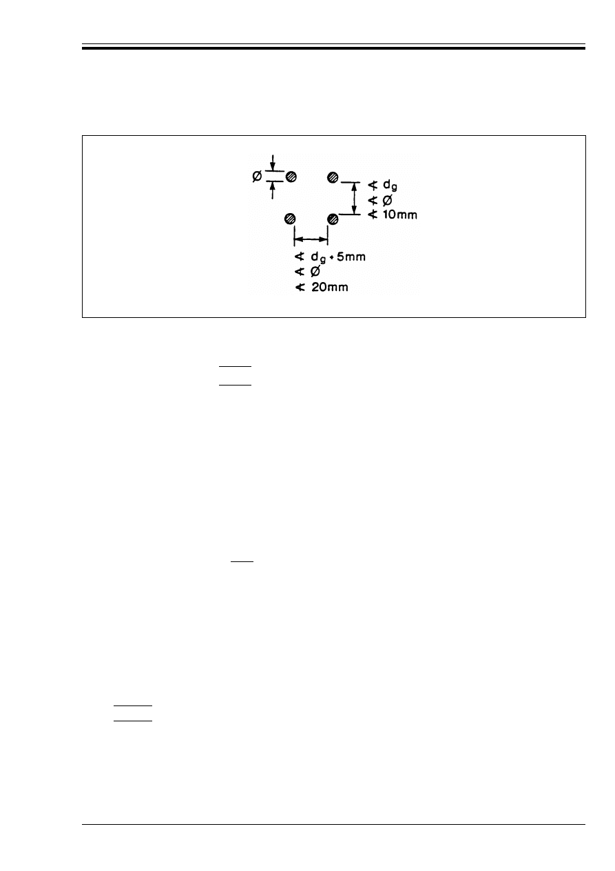
ENV 1992-1-1:1992
© BSI 12-1999
135
5.3.3.2
Post-tensioning
(1) Except for paired ducts [see 5.3.1(3)], the minimum clear spacing between individual ducts should be:
5.3.4 Anchorages and couplers for prestressing tendons
P(1) The anchorage devices used for post-tensioned tendons and the anchorage lengths in the case of
pre-tensioned tendons shall be such as to enable the full design strength of the tendons to be developed,
taking account of any repeated, rapidly changing action effects.
P(2) Where couplers are used, these shall be so placed — taking account of the interference caused by these
devices — that they do not affect the bearing capacity of the member and that any temporary anchorage
which may be needed during construction can be introduced in a satisfactory manner.
(3) Calculations for local effects in the concrete and for the transverse reinforcement should be made in
accordance with 2.5.3.7.4.
(4) In general, couplers should be located away from intermediate supports.
(5) The placing of couplers on |50 %| or more of the tendons at one cross-section should be avoided.
5.4 Structural members
In order to satisfy the requirements of Chapter 4, the following rules related to detailing arrangements
should be satisfied:
5.4.1 Columns
This clause deals with columns for which the larger dimension b is not greater than 4 times the smaller
dimension h.
5.4.1.1
Minimum dimensions
(1) The minimum permissible transverse dimension of a column cross-section is:
— |200 mm| for columns of solid section, cast in situ (vertically)
— |140 mm| for precast columns cast horizontally.
Figure 5.9 — Minimum clear spacing for pretensioned tendons
— horizontal: @ Ì
duct
or |40 mm|
— vertical
: @ Ì
duct
or |50 mm|
where Ì
duct
denotes the diameter of the duct.
Licensed copy:Heriot Watt University, 20/04/2004, Uncontrolled Copy, © BSI

ENV 1992-1-1:1992
136
© BSI 12-1999
5.4.1.2
Longitudinal and transverse reinforcement
5.4.1.2.1 Longitudinal reinforcement
(1) Bars should have a diameter of not less than 12 mm.
(2) The minimum amount of total longitudinal reinforcement A
s,min
should be derived from the following
condition:
(3) Even at laps, the area of reinforcement should not exceed the upper limit |0.08 A
c
|.
(4) The longitudinal bars should be distributed around the periphery of the section. For columns having a
polygonal cross-section, at least one bar shall be placed at each corner. For columns of circular
cross-section the minimum number of bars is |6|.
5.4.1.2.2 Transverse reinforcement
(1) The diameter of the transverse reinforcement (links, loops or helical spiral reinforcement) should not be
less than |6 mm| or |one quarter| of the maximum diameter of the longitudinal bars, whichever is the
greater; the diameter of the wires of welded mesh fabric for transverse reinforcement should not be less
than |5 mm|.
(2) The transverse reinforcement should be adequately anchored.
(3) The spacing of the transverse reinforcement along the column should not exceed the lesser of the
following three distances:
(4) The spacing should be reduced by a factor |0.6|:
i) in sections located above and below a beam or slab over a height equal to the larger dimension of the
column cross-section;
iii) near lapped joints, if the maximum diameter of the longitudinal bars is greater than |14 mm|.
(5) Where the direction of the longitudinal bars changes, (e.g. at changes in column size), the spacing of
transverse reinforcement should be calculated, while taking account of the lateral forces involved.
(6) Every longitudinal bar (or group of longitudinal bars) placed in a corner should be held by transverse
reinforcement.
(7) A maximum of |5| bars in or close to each corner can be secured against buckling by any one set of
transverse reinforcement.
5.4.2 Beams
5.4.2.1
Longitudinal reinforcement
5.4.2.1.1 Minimum and maximum reinforcement percentage
(1) The effective cross-sectional area of the longitudinal tensile reinforcement should be not less than that
required to control cracking (see 4.4.2), nor less than:
where b
t
denotes the mean width of the tension zone; for a T-beam with the flanges in compression, only
the width of the web is taken into account in calculating the value of b
t
. Sections containing less
reinforcement than that given by Equation (5.14) should be considered as unreinforced.
(5.13)
where:
f
yd
is the design yield strength of the reinforcement
N
Sd
is the design axial compression force
A
c
is the cross-section of the concrete
— 12 times the minimum diameter of the longitudinal bars;
— the least dimension of the column;
— 300 mm
|0.6| b
t
d/f
yk
@ |0.0015| b
t
d (f
yk
in N/mm
2
)
(5.14)
Licensed copy:Heriot Watt University, 20/04/2004, Uncontrolled Copy, © BSI
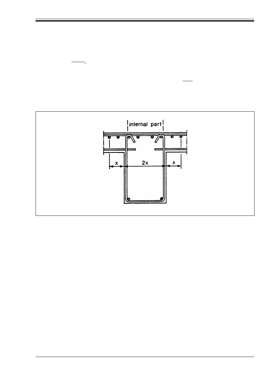
ENV 1992-1-1:1992
© BSI 12-1999
137
(2) The cross-sectional areas of the tension reinforcement and of the compression reinforcement should not
be greater than |0.04 A
c
|, other than at laps.
5.4.2.1.2 Other detailing arrangements
(1) In monolithic construction, even when simple supports have been assumed in design, the section should
be designed for bending moment arising from partial fixity of at least |25 %| of the maximum bending
moment in the span.
(2) At intermediate supports of continuous beams, the total amount of tensile reinforcement A
s
of a flanged
cross-section may be divided approximately equally between the internal and external parts of the flange.
(See Figure 5.10).
5.4.2.1.3 Length of the longitudinal tension reinforcement
(1) The envelop line of the tensile force in the longitudinal reinforcement is obtained by a horizontal
displacement a
1
of the envelop line of F
s
, F
s
being the tensile force in the longitudinal reinforcement
obtained by a cross-section analysis according to 4.3. (See Figure 5.11). If the shear reinforcement is
calculated according to the standard method, (see Section 4.3.2.4.3), a
1
= z (1 – cot!)/2 @ 0, ! being the
angle of the shear reinforcement with the longitudinal axis. If the shear reinforcement is calculated
according to the variable strut inclination method, see Section 4.3.2.4.4, a
1
= z (cotF – cot!)/2 @ 0, F being
the angle of the concrete struts with the longitudinal axis. Normally z can be taken as 0.9 d.
For reinforcement in the flange, placed outside the web [see 5.4.2.1.2(2)], a
1
should be increased by the
distance of the bar from the web. (distance x in Figure 5.10).
(2) Cut-off bars should be anchored with l
b,net
@ d from the point where they are no longer needed.
(l
b,net
: see Equation (5.4) in 5.2.3.4.1. d = effective depth of the member).
The diagram of the resisting tensile forces should lie outside the envelop line of the acting tensile force,
displaced as described in (1) above (see Figure 5.11).
Figure 5.10 — Internal and external parts of a T-beam
Licensed copy:Heriot Watt University, 20/04/2004, Uncontrolled Copy, © BSI
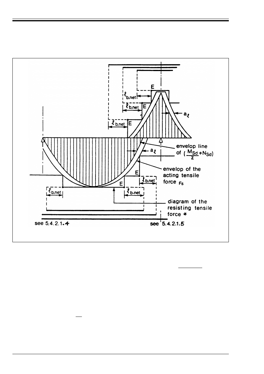
ENV 1992-1-1:1992
138
© BSI 12-1999
(3) The anchorage lengths of bent-up bars which contribute to the resistance to shear should be not less
than 1.3 l
b,net
in the tension zone and 0.7 l
b,net
in the compression zone.
5.4.2.1.4 Anchorage of bottom reinforcement at an end support
(1) Over supports with little or no end fixity it is necessary to retain not less than |one-quarter| of the steel
section present in the span;
(2) The anchorage of the reinforcement should be capable of resisting a tensile force of:
(3) The anchorage length is measured from the line of contact between the beam and its support; it should
be taken as:
* It is also permitted to use a diagram in which the resisting tensile force is progressively decreasing on the length l
b,net
.
Figure 5.11 — Envelop line for the design of flexural members. Anchorage lengths
F
s
= V
sd
· a
1
/d + N
Sd
(5.15)
where N
Sd
denotes the design axial tensile force.
— for a direct support
: |2/3| l
b,net
(see Figure 5.12 a);
— for an indirect support : l
b,net
(see Figure 5.12 b).
with l
b,net
according to Equation (5.4).
Licensed copy:Heriot Watt University, 20/04/2004, Uncontrolled Copy, © BSI
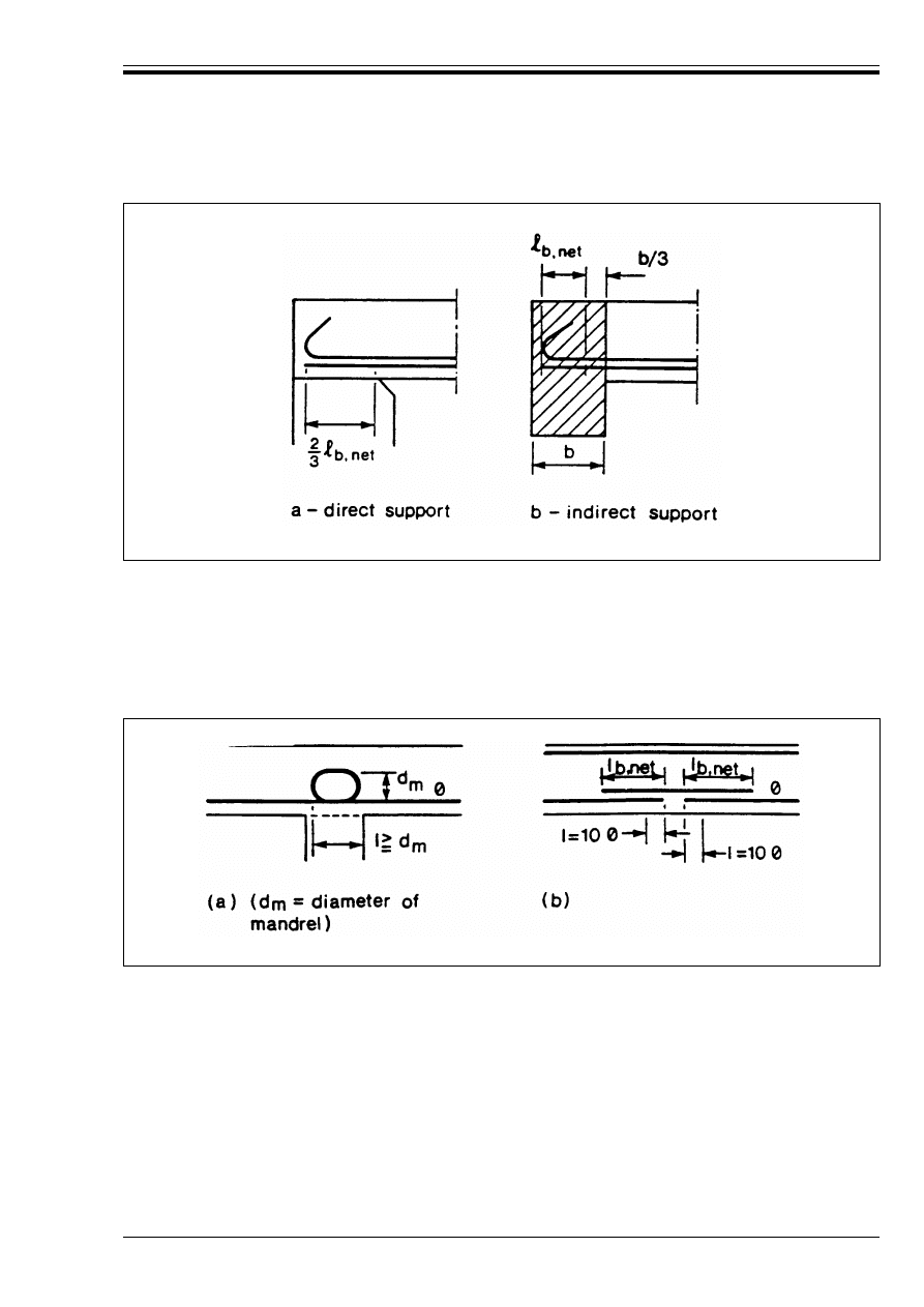
ENV 1992-1-1:1992
© BSI 12-1999
139
5.4.2.1.5 Anchorage of bottom reinforcement at intermediate supports
(1) Amount of reinforcement: 5.4.2.1.4(1) applies.
(2) Such anchorage should have a length of not less than 10 Ì (for straight bars) or not less than the
diameter of the mandrel (for hooks and bends) [see Figure 5.13(a)].
(3) In addition, it is recommended that the reinforcement used should be continuous and able to resist
accidental positive moments (settlement of the support, explosion, etc., see Figure 5.13(b).
5.4.2.2
Shear reinforcement
(1) The shear reinforcement should form an angle of 90° to 45° with the mid-plane of the structural
element.
(2) The shear reinforcement may consist of a combination of:
— links enclosing the longitudinal tensile reinforcement and the compression zone;
— bent-up bars;
— shear assemblies in the form of cases, ladders, etc. of high bond bars which are cast in without
enclosing the longitudinal reinforcement (see Figure 5.14), but should be properly anchored in the
compression and tension zones.
Figure 5.12 — Anchorages of bottom reinforcement at end supports
Figure 5.13 — Anchorage at intermediate supports
Licensed copy:Heriot Watt University, 20/04/2004, Uncontrolled Copy, © BSI
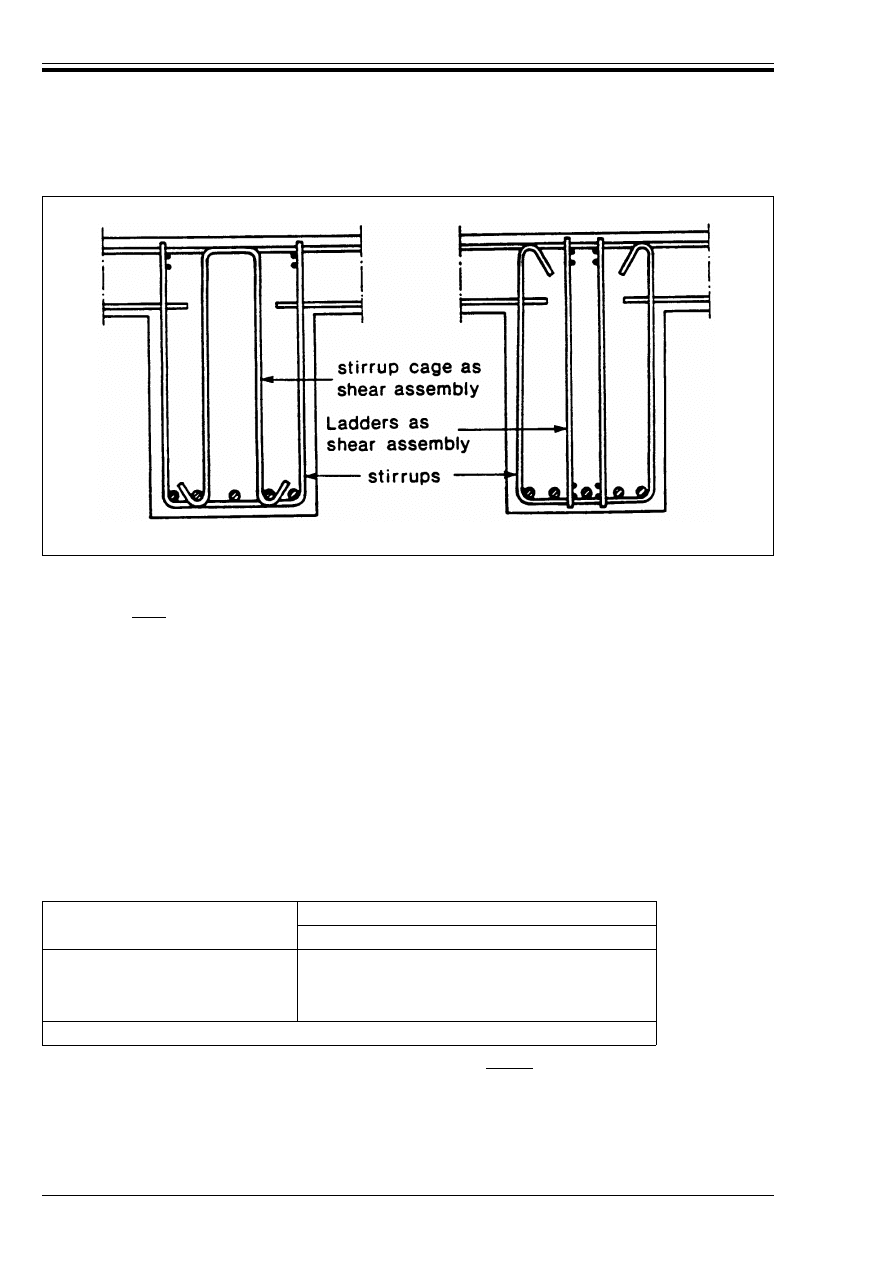
ENV 1992-1-1:1992
140
© BSI 12-1999
(3) Links should be effectively anchored. A lap joint on the leg near the surface of a web is allowed only for
high bond bars.
(4) At least |50 %| of the necessary shear reinforcement should be in the form of links.
(5) The shear ratio is given by Equation (5.16):
Table 5.5 — Minimum values for @
w
(6) The diameter of the shear reinforcement should not exceed |12 mm| where it consists of plain round
bars.
Figure 5.14 — Examples for combinations of links and shear reinforcement
@
w
= A
sw
/s.b
w
.sin!
(5.16)
where:
@
w
is the shear reinforcement ratio
A
sw
is the area of shear reinforcement within length s
s
is the spacing of the shear reinforcement
b
w
is the breadth of the web of the member
!
is the angle between the shear reinforcement and the main steel (i.e. for vertical
stirrups ! = 90° and sin ! = 1)
In general, the minimum values for @
w
are given in Table 5.5
Concrete Classes
a
Steel Classes
S220
S400
S500
C12/15 and C20/25
0.0016
0.0009
0.0007
C25/30 to C35/45
0.0024
0.0013
0.0011
C40/50 to C50/60
0.0030
0.0016
0.0013
a
as assumed in the design.
Licensed copy:Heriot Watt University, 20/04/2004, Uncontrolled Copy, © BSI

ENV 1992-1-1:1992
© BSI 12-1999
141
(7) The maximum longitudinal spacing s
max
of successive series of stirrups or shear assemblies is defined
by the following conditions (with V
Sd
, V
Rd1
and V
Rd2
as defined in 4.3.2):
(8) The maximum longitudinal spacing of bent-up bars is defined by:
(9) The transverse spacing of the legs in a series of shear links should not exceed:
(10) The provisions for the control of diagonal cracking are given in 4.4.2.3(5).
5.4.2.3
Torsional reinforcement
(1) The torsion links should be closed amd be anchored by means of laps or according to a) of Figure 5.7 and
form an angle of 90° with the axis of the structural element.
(2) The provisions of 5.4.2.2(3)–(6) are also valid for the longitudinal bars and links of beams subjected to
torsion.
(3) The longitudinal spacing of the torsion links should not exceed |u
k
/8| (see 4.3.3.1, Figure 4.15, for the
notation).
(4) The spacing in (3) above should also satisfy the requirements in 5.4.2.2(7) for maximum spacing of
links.
(5) The longitudinal bars should be so arranged that there is at least one bar at each corner, the others
being distributed uniformly around the inner periphery of the links, spaced at not more than |350 mm|
centres.
5.4.2.4
Surface reinforcement
(1) In certain cases it may be necessary to provide surface reinforcement either to control cracking or to
ensure adequate resistance to spalling of the cover.
(2) Skin reinforcement to control cracking should normally be provided in beams over 1 m deep
[see 4.4.2.3(4)].
(3) Surface reinforcement to resist spalling arising, for example, from fire or where bundled bars or bars
greater than 32 mm diameter are used, should consist of wire mesh or small diameter high bond bars and
be placed outside the links as indicated in Figure 5.15.
(4) The minimum cover needed for the surface reinforcement is given in 4.1.3.3(6) and (7).
(5) The area of surface reinforcement A
s,surf
should be not less than |0.01| A
ct,ext
in the direction parallel
to the beam tension reinforcement.
(6) The longitudinal bars of the surface reinforcement may be taken into account as longitudinal bending
reinforcement and the transverse bars as shear reinforcement provided that they meet the requirements
for the arrangement and anchorage of these types of reinforcement.
(7) Any surface reinforcement in prestressed beams can be taken into account as in (5) and (6) above.
— if
V
Sd
r 1/5 V
Rd2
: s
max
= 0.8 d 8 300 mm
(5.17)
— if 1/5 V
Rd2
< V
Sd
r 2/3 V
Rd2
: s
max
= 0.6 d 8 300 mm
(5.18)
— if
V
Sd
> 2/3 V
Rd2
: s
max
= 0.3 d 8 200 mm
(5.19)
(for V
Rd2
, see Section 4.3.2.4 Equations 4.25 and 4.26
s
max
= |0.6| d (1 + cot !)
(5.20)
if V
Sd
r 1/5 V
Rd2
: s
max
= d or |800| mm whichever is the smaller
for V
Sd
> 1/5 V
Rd2
: Equation 5.18 or 5.19 applies.
A
ct,ext
denotes the area of the tensile concrete external to the links, defined by Figure 5.15.
Licensed copy:Heriot Watt University, 20/04/2004, Uncontrolled Copy, © BSI
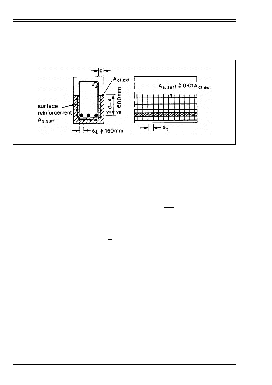
ENV 1992-1-1:1992
142
© BSI 12-1999
5.4.3 Cast in situ solid slabs
(1) This section applies to two-ways solid slabs and to one-way solid slabs where b and l
eff
T 4h (see 2.5.2).
5.4.3.1
Minimum thickness
(1) For a solid slab, the absolute minimum thickness is |50 mm|.
5.4.3.2
Flexural reinforcement
5.4.3.2.1 General
(1) For the detailing of the main reinforcement, 5.4.2.1 applies with a
1
= d in 5.4.2.1.3.
(2) Secondary transverse reinforcement should be provided in one-way slabs
Generally, this secondary transverse reinforcement should be at least |20 %| of the principal
reinforcement.
(3) 5.4.2.1.1(1) and(2) give the minimum and the maximum steel percentages in the main direction.
(4) The maximum spacing of the bars is as follows:
— for the principal reinforcement, |1.5 h d 350 mm|, where h denotes the total depth of the slab;
— for the secondary reinforcement, |2.5 h d 400 mm|.
(5) Rules 5.4.2.1.3(1)–(3), 5.4.2.1.4(1)–(3) and 5.4.2.1.5(1)–(2) apply.
5.4.3.2.2 Reinforcement in slabs near supports
(1) In slabs, half the calculated span reinforcement should continue up to the support and be anchored
therein.
(2) Where partial fixity occurs along one side of slab, but is not taken into account in the analysis, the top
reinforcement should be capable of resisting not less than one quarter of the maximum moment in the
adjacent span; this reinforcement should be provided along a length of not less than 0.2 times the adjacent
span measured from the inner face of the support.
5.4.3.2.3 Corner reinforcement
(1) If the detailing arrangements at a support are such that lifting of the slab at a corner is restrained,
suitable reinforcement should be provided.
5.4.3.2.4 Reinforcement at the free edges
(1) Along a free (unsupported) edge, a slab should normally contain longitudinal and transverse
reinforcement generally arranged as shown in Figure 5.16.
(2) The normal reinforcement provided for a slab may act as edge reinforcement
Figure 5.15 — Surface reinforcement
Licensed copy:Heriot Watt University, 20/04/2004, Uncontrolled Copy, © BSI
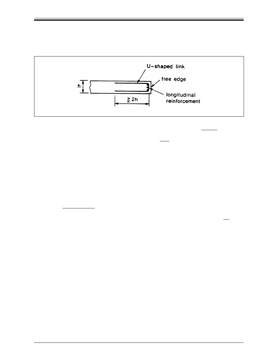
ENV 1992-1-1:1992
© BSI 12-1999
143
5.4.3.3
Shear reinforcement
(1) A slab in which shear reinforcement is provided should have a depth of at least |200 mm|.
(2) In detailing the shear reinforcement, 5.4.2.2 applies except where modified by the following rules.
Where shear reinforcement is required, this should not be less |60 %| of the values in Table 5.5 for beams.
(3) In slabs if V
Sd
r 1/3 V
Rd2
, (see 4.3.2), the shear reinforcement may consist entirely of bent-up bars or of
shear assemblies.
(4) The maximum longitudinal spacing of successive series of links is given by Equations 5.17 to 5.19
neglecting the limits given in mm. The maximum longitudinal spacing of bent-up bars is s
max
= d.
(5) The distance between the inner face of a support, or the circumference of a loaded area, and the nearest
shear reinforcement taken into account in the design should not exceed d/2 for bent-up bars. This distance
should be taken at the level of the flexural reinforcement; if only a single line of bent-up bars is provided,
their slope may be reduced to 30°. [Figure 5.17 b)]
(6) It may be assumed that one bent-up bar takes up the shear force over a length of 2d.
(7) Only the following reinforcement may be taken into account as punching shear reinforcement:
— reinforcement located in a zone bounded by a contour line situated at a distance not
exceeding |1.5 d or 800 mm|, whichever is the smaller, from the periphery of the loaded area; this
condition applies in all directions;
— bent-up bars passing over the loaded area [Figure 5.17 b)] or at a distance not exceeding |d/4| from
the periphery of this area [Figure 5.17 c)].
Figure 5.16 — Edge reinforcement for a slab
Licensed copy:Heriot Watt University, 20/04/2004, Uncontrolled Copy, © BSI
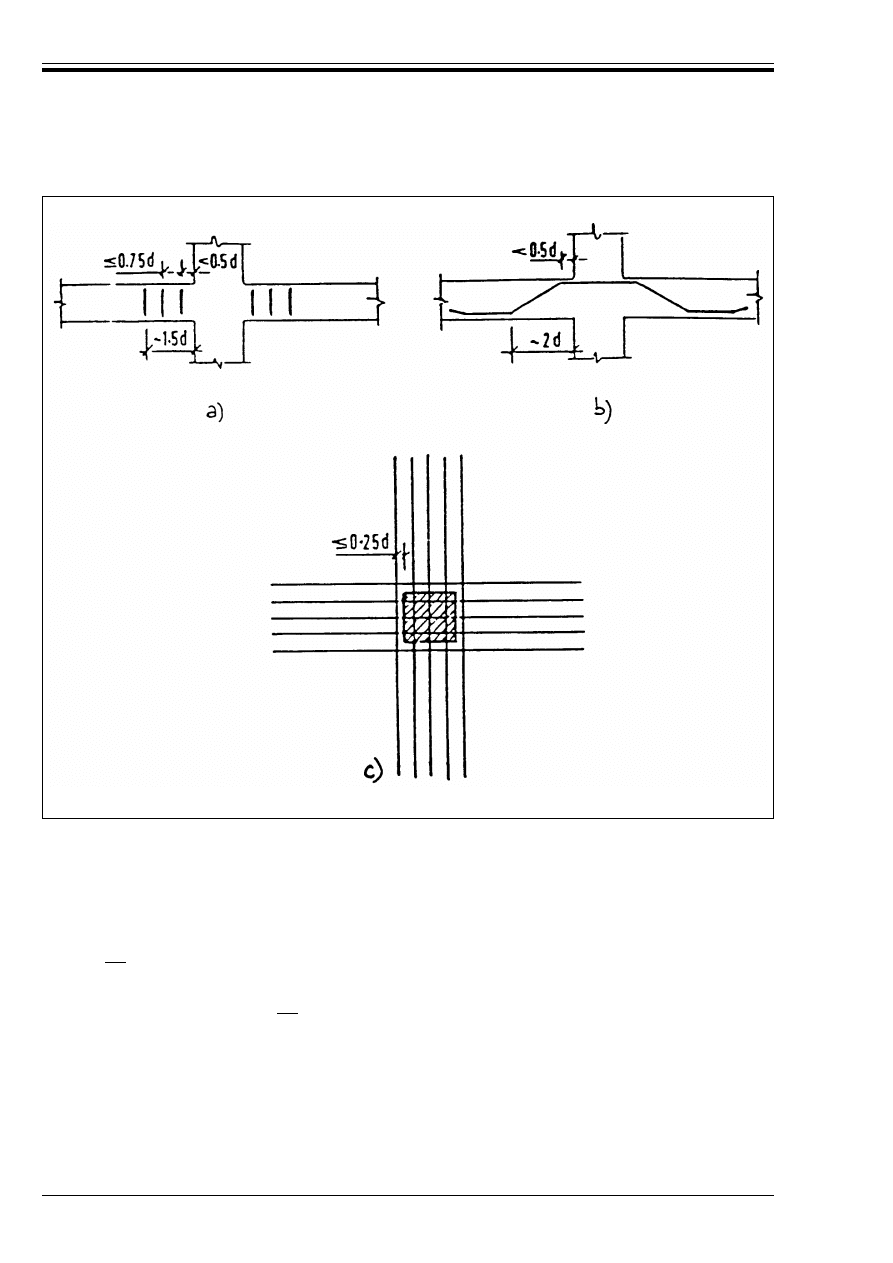
ENV 1992-1-1:1992
144
© BSI 12-1999
5.4.4 Corbels
(1) The reinforcement, corresponding to the ties considered in the design model (2.5.3.7), should be fully
anchored beyond the node under the bearing plate by using U-hoops or anchorage devices, unless a length
l
b,net
is available between the node and the front of the corbel, l
b,net
should be measured from the point
where the compression stresses change their direction.
(2) In corbels with h
c
T 300 mm, when the area of the primary horizontal tie A
s
is such that
(where A
c
denotes the sectional area of the concrete in the corbel at the column), then closed stirrups,
having a total area not less than |0.4| A
s
, should be distributed over the effective depth d in order to cater
for splitting stresses in the concrete strut. They can be placed either horizontally (Figure 5.18a) or inclined
(Figure 5.18b).
Figure 5.17 — Shear reinforcement near to a support
A
s
T |0.4| A
c
f
cd
/f
yd
(5.21)
Licensed copy:Heriot Watt University, 20/04/2004, Uncontrolled Copy, © BSI
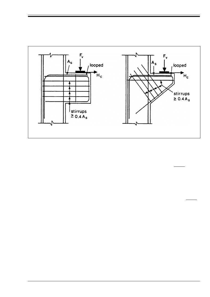
ENV 1992-1-1:1992
© BSI 12-1999
145
5.4.5 Deep beams
(1) The reinforcement, corresponding to the ties considered in the design model, should be fully anchored
beyond the nodes by bending up the bars, by using U-hoops or by anchorage devices, unless a sufficient
length is available between the node and the end of the beam permitting an anchorage length of l
b,net.
(2) Deep beams should normally be provided with a distributed reinforcement near both sides, the effect of
each being equivalent to that of an orthogonal mesh with a reinforcement ratio of at least |0.15 %| in both
directions.
5.4.6 Anchorage zones for post-tensioning forces
(1) Anchorage zones should always be provided with distributed reinforcement near all surfaces in the form
of an orthogonal mesh.
(2) Where groups of post-tensioned cables are located at a certain distance from each other, suitable links
should be arranged at the ends of the members, as a protection against splitting.
(3) At any part of the zone, the reinforcement ratio on either side of the block should be at least |0.15 %|
in both directions.
(4) All reinforcement should be fully anchored.
(5) Where a strut and tie model has been used to determine the transverse tensile force, the following
detailing rules should be followed:
— the steel area actually required to provide the tie force, acting at its design strength, should be
distributed in accordance with the actual tensile stress distribution, i.e. over a length of the block
approximately equal to its greatest lateral dimension.
— closed stirrups should be used for anchorage purposes.
— all the anchorage reinforcement should preferably be formed into a 3-dimensional orthogonal grid.
(6) Special attention should be given to anchorage zones having cross sections different in shape from that
of the general cross-section of the beam.
Figure 5.18a — Reinforcement of corbel with
horizontal stirrups
Figure 5.18b — Reinforcement of corbel with
inclined stirrups
Licensed copy:Heriot Watt University, 20/04/2004, Uncontrolled Copy, © BSI
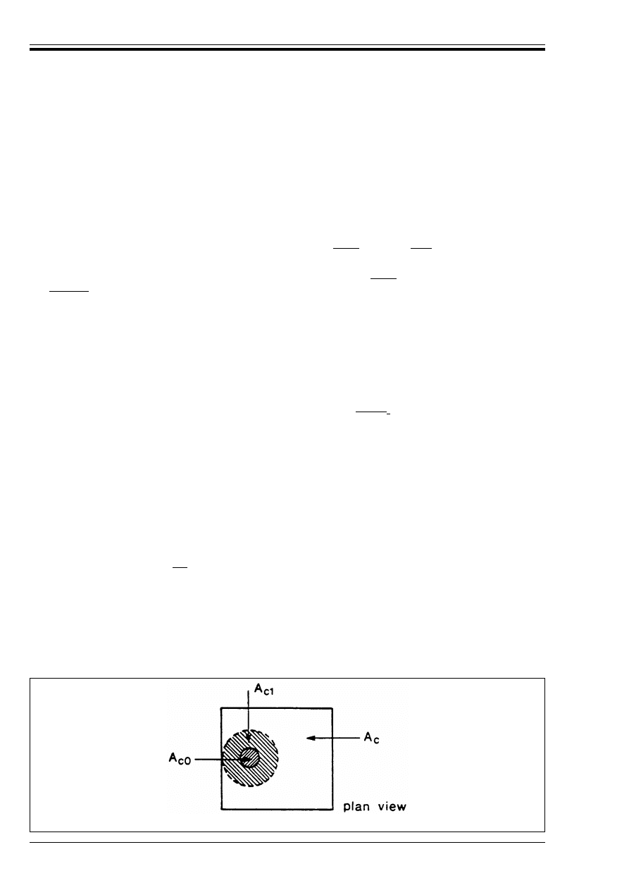
ENV 1992-1-1:1992
146
© BSI 12-1999
5.4.7 Reinforced concrete walls
5.4.7.1
General
(1) This clause deals with reinforced concrete walls of which the length measured horizontally is at least
equal to four times the thickness, and in which the reinforcement is taken into account in the strength
analysis. The amount and proper detailing of reinforcement may be derived from a strut and tie model
(see 2.5.3.6). For walls subjected predominantly to out-of-plane bending the rules for slabs apply
(see 5.4.3).
5.4.7.2
Vertical reinforcement
(1) The area of the vertical reinforcement should be between |0.004| A
c
and |0.04| A
c
.
(2) In general, half of this reinforcement should be located at each face.
(3) The distance between two adjacent vertical bars shall not exceed |twice| the wall thickness
or |300 mm| whichever is the lesser.
5.4.7.3
Horizontal reinforcement
(1) Horizontal reinforcement running parallel to the faces of the wall (and to the free edges) should be
provided and arranged at each surface between the vertical reinforcement and the nearest surface. It
should not be less than 50 % of the vertical reinforcement.
(2) The spacing between two adjacent horizontal bars should not be greater than 300 mm.
(3) The diameter should not be less than one quarter of that of the vertical bars.
5.4.7.4
Transverse reinforcement
(1) If the area of the load carrying vertical reinforcement exceeds |0.02 A
c
| this reinforcement should be
enclosed by stirrups according to 5.4.1.2.2.
5.4.8 Particular cases
5.4.8.1
Concentrated forces
(1) Where one or more concentrated forces act at the end of a member or at the intersection of two structural
members, local supplementary reinforcement should be provided capable of resisting the transverse tensile
forces caused by these forces.
(2) This supplementary reinforcement may consist of links or of layers of reinforcement bent in the shape
of hair pins.
(3) For a uniform distribution of load on area A
co
, (Figure 5.19), the concentrated resistance force can be
determined as follows:
F
Rdu
= A
co
f
cd
ßA
cl
/A
co
8 |3.3| f
cd
A
co
(5.22)
where
f
cd
= f
ck
/*
c
A
co
denotes the loaded area,
A
cl
denotes the maximum area corresponding geometrically to A
co
, having the same centre of
gravity, which it is possible to inscribe in the total area A
c
, situated in the same plane as the
loaded area.
Figure 5.19 — Definition of the areas to be introduced in Equation (5.22)
Licensed copy:Heriot Watt University, 20/04/2004, Uncontrolled Copy, © BSI
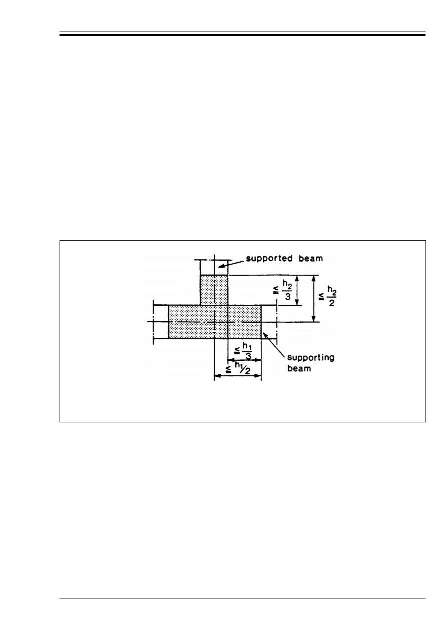
ENV 1992-1-1:1992
© BSI 12-1999
147
If A
c
and A
co
correspond geometrically and have the same centre of gravity: A
c1
= A
c
.
The value of F
Rdu
obtained from Equation 5.22 should be reduced if the load is not uniformly distributed
on area A
co
or if it is accompanied by large shear forces.
This method does not apply to the anchorages of prestressing tendons (see 2.5.3.7.4).
5.4.8.2
Forces associated with change in direction
P(1) At points where considerable changes in the direction of the internal forces occur, the associated radial
forces shall be resisted by means of suitably anchored additional reinforcement or by detailing the normal
reinforcement in a special way.
5.4.8.3
Indirect supports
P(1) n the case of a connection between a supporting beam and a supported beam, “suspension”
reinforcement shall be provided and designed to resist the total mutual support reaction.
(2) The suspension reinforcement should consist preferably of links surrounding the principal
reinforcement of the supporting member. Some of these links may be distributed outside the volume of
concrete which is common to the two beams, as indicated in Figure 5.20.
5.5 Limitation of damage due to accidental actions
5.5.1 Tying system
In cases where it is found necessary to make specific provision to limit potential damage [2.1(2)], ties may
be used if appropriate.
(1) Interaction between elements may be obtained by tying the structure together using:
a) peripheral ties;
b) internal ties;
c) vertical ties.
(2) Where a building is divided by expansion joints into structurally independent sections, each section
should have an independent tying system.
(3) Ties perform two distinct functions:
a) to prevent local damage due to accidental actions such as impact or explosion.
b) to provide alternative load paths should local damage occur.
h
1
height of the supporting beam
h
2
height of the supported beam (h
2
< h
1
)
Figure 5.20 — Extent of the intersection zone for the connection of secondary beams
Licensed copy:Heriot Watt University, 20/04/2004, Uncontrolled Copy, © BSI

ENV 1992-1-1:1992
148
© BSI 12-1999
5.5.2 Proportioning of ties
(1) Tie sections should be the greater of either, that necessary to withstand loads generated by appropriate
accidental actions as specified in Eurocode 1 or, that necessary to provide a specified load path around a
damaged zone.
(2) In the design of the ties, the reinforcement may be assumed to be acting at its characteristic strength.
(3) Reinforcement provided for other purposes may be regarded as forming part of, or the whole of, these
ties.
(4) For the purposes of tie design, forces other than those generated directly by accidental actions or
consequent upon the occurrence of actual local damage may be ignored.
5.5.3 Continuity and anchorage
(1) Ties should be continuous between the boundaries of the building structure.
(2) Continuity is obtained by effective lapping provided the splice length is l
s
= 2l
b
and the splice is enclosed
by stirrups or spirals with s r 100 mm. In some cases continuity may be obtained by welding or by the use
of mechanical connectors.
(3) Ties should be provided with mechanical anchorage at the periphery of the structure.
6 Construction and workmanship
6.1 Objectives
P(1) This section provides a series of minimum specification requirements for the standard of workmanship
that must be achieved on site in order to ensure that the design assumptions in this code are valid and
hence that the intended levels of safety and of durability will be attained.
(2) This section is neither intended as, nor extensive enough for, a contract document.
6.2 Tolerances
6.2.1 Tolerances — general
P(1) In order to ensure the required properties of the structure, the tolerances must be clearly defined
before construction work starts.
P(2) For durability reasons, independently from the defined tolerances, the cover to reinforcement shall not
be less than the minimum values given in 4.1.3.3.
P(3) The dimensions given on the working drawings shall be observed with the appropriate tolerances.
6.2.2 Tolerances with regard to structural safety
(1) The following deviations % 1 with respect to the nominal cross sectional dimensions 1 can — except for
concrete cover, see 6.2.3 below — be regarded as admissible on the basis of the partial safety coefficients
*
F
and *
M
as given in 2.3.3.1 and 2.3.3.2 respectively.
a) In relation to the dimensions of the concrete section (total depth of a beam or of a slab, width of a beam
or a web, lateral dimensions of a column) and in relation to the effective depth:
for 1 r 150 mm : % 1 = ± 5 mm
(6.1)
for 1 =
400 mm : % 1 = ± 15 mm
(6.2)
for 1 T 2 500 mm : % 1 = ± 30 mm
(6.3)
with linear interpolation for other values of 1.
Licensed copy:Heriot Watt University, 20/04/2004, Uncontrolled Copy, © BSI

ENV 1992-1-1:1992
© BSI 12-1999
149
b) for the position of the prestressing tendons compared with the design position:
where 1 denotes the depth or width of the cross section.
(2) Tolerances other than those defined in paragraph (1) above can also be specified provided that it can be
demonstrated that they do not reduce the required level of safety.
6.2.3 Tolerances for concrete cover
(1) For the tolerances of concrete cover to reinforcement, e.g. the difference between the nominal and the
minimum cover, 4.1.3.3(8) applies. No positive permitted deviation is specified.
6.2.4 Tolerances for construction purposes
(1) For other purposes, such as for example construction or dimensional tolerances in buildings as a whole,
stricter tolerances than defined in 6.2.2 may be required. These values should be specified separately from
this Code. For the maximum sag of slabs, however, 4.4.3.1(5) and (6) apply.
6.3 Construction rules
6.3.1 Concrete
P(1) The concrete used in construction shall be such that its specified properties will be maintained over
the life of the structure.
(2) For the construction rules related to concrete and concrete technology, the relevant Sections in
ENV 206 apply.
6.3.2 Formwork and falsework
6.3.2.1
Basic requirements
P(1) Formwork and falsework shall be designed and constructed so that they are capable of resisting all
actions which may occur during the construction process. They shall remain undisturbed until the concrete
has achieved sufficient strength to withstand the stresses to which it will be subjected on stripping or
release, with an acceptable margin of safety.
P(2) The formwork and falsework shall be sufficiently stiff to ensure that the tolerances for the structure
are satisfied and that its loadbearing capacity is not affected.
P(3) The general lay-out of the formwork shall be such that the correct placing of reinforcement and
tendons as well as correct compaction of the concrete is possible.
P(4) The formwork and the falsework shall be designed and erected (in accordance with national standards)
by suitably trained persons. Supervision and control shall be such as to ensure that the erection is
completed in accordance with the drawings and specifications.
P(5) The formwork shall be capable of being removed from the concrete without causing shock or damage.
(6) Where necessary, the camber built into the formwork should be that required by the designer of the
structure and falsework.
(7) Ground support for the falsework should also be constructed by suitably trained personnel in
accordance with the drawings and specifications. Deformations and displacements imposed by
prestressing should be taken into account in the design of the falsework.
(8) Joints between the panels of the formwork should be adequately tight.
for 1 < 200 mm:
— for tendons which are part of a strand, single tendons and strands:
% 1 = ± 0.025 1
(6.4)
for 1 > 200 mm:
— for tendons which are part of a strand and for single tendons:
% 1 = ± 0.025 1
or % 1 = ± 20 mm
(6.5)
— for strands:
% 1 = ± 0.04 1
or % 1 = ± 30 mm
(6.6)
Licensed copy:Heriot Watt University, 20/04/2004, Uncontrolled Copy, © BSI

ENV 1992-1-1:1992
150
© BSI 12-1999
(9) The internal surface of the formwork must be clean. Approved mould-release agents should be applied
in continuous and uniform layers on the internal surface and the concrete should then be placed while
these agents are still effective. Any possible detrimental influence of these agents on the concrete surface
has to be taken into consideration.
(10) Formwork spacers left in the concrete should not impair its durability or appearance
6.3.2.2
Surface finish
P(1) The formwork shall be designed and constructed so that there is no loss of fines, or blemish of the
concrete surface.
P(2) Where a particular grade or type of finish is required for practical or aesthetic reasons, the
requirements shall be specified directly or by reference to appropriate national or international documents
or by sample surfaces.
6.3.2.3
Temporary works inserts
P(1) Temporary works inserts may be necessary to assist in maintaining formwork, or bar reinforcement
or ducts or other similar items, in place until the concrete has hardened.
P(2) Such inserts shall not introduce unacceptable loading on the structure, shall not react harmfully with
the constituents of the concrete or reinforcement or prestressing steel, and shall not produce unacceptable
surface blemishes.
(3) The use of light alloy inserts (aluminium etc) is prohibited.
6.3.2.4
Removal of formwork and falsework
P(1) The time at which formwork and falsework is removed shall be determined by consideration of the
following criteria:
a) The stresses that will be induced in the concrete when the formwork/falsework has been removed;
b) The concrete strength at the time of removal;
c) The ambient climatic conditions and the measures available to protect the concrete once the formwork
is removed;
d) The presence of re-entrant angle formwork, which should be removed as soon as possible, while
complying with other removal criteria.
(2) General information on curing and on striking formwork is given in 10.6, 10.7 and 10.8 of ENV 206.
(3) The time between casting and removal of the formwork depends mainly on the strength development
of the concrete (see ENV 206, Table 13) and on the function of the formwork. In the absence of more
accurate data, the following minimum periods are recommended:
| 2| days for non-load bearing parts of formwork (e.g. vertical formwork of beams; formwork for
columns and walls);
| 5| days for the formwork of slabs cast in situ;
|10| days for direct load-bearing formwork, e.g. soffits of beams or slabs.
Where sliding or climbing formwork is used, shorter periods than recommended above may be permitted.
6.3.3 Reinforcing steel
6.3.3.1
Basic requirements
P(1) Reinforcing steel shall comply with the requirements of 3.2 of this Code, with relevant Euronorms or,
where these do not exist, with CEN, ISO, or national standards, or shall be approved by the National
Building Regulations Control Authority.
(2) Only steel specified in the design documents may be used as reinforcement.
6.3.3.2
Transport, storage and fabrication of the reinforcement
P(1) Steel reinforcing bars, welded mesh reinforcement and prefabricated reinforcement cages shall be
transported, stored, bent and placed in position so that they do not suffer any damage.
P(2) The surface condition of the reinforcement shall be examined prior to use, to ensure that it is free from
deleterious substances which may adversely affect the steel or concrete or the bond between them.
P(3) Reinforcing steel shall be cut and bent in accordance with appropriate international or national
standards.
Licensed copy:Heriot Watt University, 20/04/2004, Uncontrolled Copy, © BSI

ENV 1992-1-1:1992
© BSI 12-1999
151
(4) The following should be avoided:
— Mechanical damage (e.g. notches or dents);
— Rupture of welds in prefabricated reinforcement cages and in welded fabrics;
— Surface deposits damaging bond properties;
— Lack of identification of reinforcement;
— Reduction of the section through corrosion, beyond certain permissible limiting values.
6.3.3.3
Welding
P(1) Welding must only be carried out on reinforcing steel that is suitable for welding.
P(2) Welded connections must be made and checked by persons suitably trained in welding of
reinforcement.
P(3) Welding shall be performed in accordance with international or national standards.
P(4) Where a risk of fatigue exists, the welding of reinforcement must conform to special requirements as
given in relevant standards.
P(5) The production and checking of the welded connections shall comply with the relevant requirements
in international or national standards.
(6) Welding methods permitted include:
— electric flash welding;
— electric resistance welding;
— electric arc welding (with coated electrodes or under a protective gas envelope);
— high pressure gas welding.
6.3.3.4
Joints
P(1) The length and position of lapped joints shall be in accordance with the design and the drawings. If
the bar lengths delivered to the site do not conform with the drawings, then modifications shall only be
introduced with the approval of the designer or of the supervisory authority.
P(2) In general, reinforcing bars shall not be welded at or near bends in a bar.
(3) Joints made with mechanical connecting devices should be carried out in accordance with
Clause 5.2.3.5 of this Code and with the specified Standards or Approval documents.
6.3.3.5
Fabrication, assembly and placing of the reinforcement
P(1) The assembly of the reinforcement shall be robust enough to ensure that the bars do not shift from
their prescribed position during transportation, placing and concreting. The specified cover to the
reinforcement shall be maintained by the use of approved chairs and spacers.
P(2) The tolerances required for the fixing of reinforcement shall be as given in 6.2. Alternatively, they
shall be stated in the contract documents.
P(3) Bending should be carried out by mechanical methods, at constant speed without jerking, with the aid
of mandrels so that the bent part has a constant curvature. If the ambient temperature is lower than a
specified value, additional precautions may be needed.
P(4) The reinforcement shall be secured against any displacement and the position of the reinforcement
shall be checked before concreting.
P(5) In areas of congested reinforcement, sufficient spacing of the bars shall be provided to allow proper
compaction of the concrete.
6.3.4 Prestressing steel
6.3.4.1
Basic requirements
P(1) Prestressing steel shall comply with the requirements of 3.3 of this Code, the relevant Euronorms, or
where these do not exist, with CEN, ISO or national standards, or shall be approved by the National
Building Regulations Control Authority.
P(2) The prestressing devices (anchorages, couplers, sheaths and ducts) shall comply with the
requirements of 3.4 of this Code, the relevant Euronorms, or where these do not exist, with CEN, ISO or
national standards, or shall be approved by the National Building Regulations Control Authority.
Licensed copy:Heriot Watt University, 20/04/2004, Uncontrolled Copy, © BSI

ENV 1992-1-1:1992
152
© BSI 12-1999
(3) The tendons, (wire, bars, cables), anchorage devices, couplers and sheaths used shall be those in the
project design documents. They shall be capable of being identified as such.
6.3.4.2
Transport and storage of the tendons
P(1) Tendons, sheaths, anchorage devices and couplers shall be protected from harmful influences during
transport and storage and also when placed in the structure, until after concreting has taken place.
(2) During transport and storage of the tendons, the following should be avoided:
— any type of chemical, electro-chemical or biological attack liable to cause corrosion;
— any damage to the tendons;
— any contamination liable to affect the durability or bond properties of the tendons;
— any deformation of the tendons, not provided for in the design;
— any unprotected storage, exposure to main or contact with the ground;
— the use of water transport without suitable packaging;
— welding in the vicinity of prestressing tendons without the provision of special protection (from
splashes).
(3) For the sheaths, the following should be taken into consideration:
— local damage and corrosion inside should be avoided;
— water-tightness should be ensured;
— it should be resistant to mechanical and chemical attack.
6.3.4.3
Fabrication of tendons
P(1) The devices used in jointing the tendons, for their anchorage and coupling shall be as specified in
Standards or Approval Documents. The prestressing members shall be assembled and placed in position
in accordance with the Standards or Approval documents. The sheaths and their connections shall be as
specified in the project design documents.
(2) Particular consideration should be given to
— maintaining the identification marks on all materials;
— the appropriate methods for cutting;
— the straight entry into the anchorage and couplers as required by the manufacturer;
— assembly;
— transportation; when lifting by crane, any local crushing or bending of the tendons should be avoided.
6.3.4.4
Placing of the tendons
P(1) Placing of the tendons shall be carried out in compliance with the criteria relating to:
— the concrete cover and the spacing of the tendons;
— the permissible tolerances in respect of the position of the tendons, couplers and anchorages;
— the ease with which the concrete can be cast.
P(2) The tolerances required for the placing of the prestressing tendons shall be those given
in 6.2. Alternatively they shall be stated in the contract documents.
(3) The sheaths should be fixed carefully according to the designer’s specification of dimensions, spacers
and supports.
(4) After placing the sheaths in position, vents should be provided at both ends and at their high points, as
well as at all points where air or water may accumulate; in the case of sheaths of considerable length,
vents are also needed at intermediate positions.
(5) The sheaths should be protected from penetration of extraneous materials until the completion of
grouting.
6.3.4.5
Tensioning of the tendons
P(1) Prestressing shall be in accordance with a pre-arranged stressing programme.
P(2) Written instructions shall be provided at the site or in the factories or plants on the prestressing
procedure to be followed.
P(3) Workmen and staff engaged in stressing shall be skilled and have had special training.
Licensed copy:Heriot Watt University, 20/04/2004, Uncontrolled Copy, © BSI

ENV 1992-1-1:1992
© BSI 12-1999
153
P(4) During prestressing, suitable safety measures should be taken and be recorded by an engineer.
6.3.4.5.1 Pre-tensioning
(1) In the case of pre-tensioning the instructions for prestressing shall specify:
— the prestressing tendons and the prestressing devices;
— any special sequence in which the prestressing tendons are to be tensioned;
— the jack pressure or the forces at the jacks which must not be exceeded;
— the final pressure which must be attained after stressing has been completed or the corresponding
forces at the jack;
— the maximum permissible extension of the tendons and slip in the anchorages;
— the manner and sequence in which the tendons are to be released;
— the required concrete strength at the time of release, which should be checked;
— operational suitability of re-useable anchorage components.
(2) The necessity for a temporary protection of the tendons after tensioning and before casting should be
checked. Where necessary, the protective material should not affect bond and should have no detrimental
effect on the steel or the concrete.
6.3.4.5.2 Post-tensioning
(1) The following shall be
a) Specified by the designer:
— the prestressing process to be employed;
— the type and grade of the prestressing steel;
— the number of bars or wires in the individual tendons;
— the required concrete strength prior to tensioning;
— the order in which successive tendons should be tensioned, specifying the location where the
tension is to be applied;
— where appropriate, the time of the removal of the falsework during tensioning;
— the force required to be developed at the jack;
— the design elongation required;
— the maximum slip;
— the number, type and location of couplers.
b) recorded by the supervising engineer during the tensioning process:
— the type of prestressing devices used which should be calibrated;
— the elongation measured on site;
— the measured pressure in the jacks;
— the observed value of slip;
— the deviation of the measured values from the design values.
— the actual concrete strength;
— the actual order in which successive tendons are tensioned;
— where appropriate, the time at which the formwork has been removed.
6.3.4.6
Grouting and other protective measures
6.3.4.6.1 General
P(1) Tendons placed in sheaths or ducts in the concrete, couplers and anchorage devices shall be protected
against corrosion.
P(2) Should the delay between stressing and grouting exceed the time permitted, then protection of the
tendons shall continue until grouting takes place.
P(3) Where temporary protection is provided, the material used shall have an approval document and shall
not have a deleterious effect on the prestressing steel or on the cement grout.
Licensed copy:Heriot Watt University, 20/04/2004, Uncontrolled Copy, © BSI

ENV 1992-1-1:1992
154
© BSI 12-1999
P(4) Written instructions shall be provided for the site or the works for the preparation and execution of
the grouting.
P(5) If frost is liable to occur, measures shall be taken to prevent freezing of water in sheaths which are not
yet grouted. After a period of frost, the sheaths should be free from ice before grouting is started.
(6) Corrosion protection of the tendons is ensured by filling all voids with a suitable grouting material
(usually cement mortar); as a rule, the anchorage should be enveloped in concrete or mortar.
The above objective is met by:
— using approved grout materials (must remain alkaline, no harmful components) and by covering the
tendons completely:
— filling the ducts completely (including voids between tendons) with a grout which after hardening
fulfils the structural requirements (strength, bond, modulus of elasticity, shrinkage).
6.3.4.6.2 Cement grout
P(1) The cement grout used shall have adequate properties e.g.
— high fluidity and cohesion when plastic;
— low shrinkage deformation when hardening;
— adequate strength and resistance to freezing when hard;
— no loss of fines (“bleeding”).
P(2) Appropriate materials (type of cement, admixtures) shall be used and the mixing process (batching,
w/c-ratio, procedure, time) shall ensure the required properties.
P(3) Chlorides (as % by mass of cement) from all sources shall not exceed the values given in the national
standards.
P(4) For the types of cements used for grouting, see EN... (yet to be drafted)
6.3.4.6.3 Instructions to the site
P(1) Before grouting starts, the following preconditions shall be fulfilled:
— operational equipment (including “stand by” grout pump to avoid interruptions in the event of
malfunction);
— permanent supplies of water under pressure and of compressed air;
— materials batched (excess to allow for overflow);
— ducts free of harmful material (e.g. water, ice);
— vents prepared and identified;
— preparation of control tests for grout;
— in case of doubt, grouting trial on representative ducts;
— grout flow not affected.
P(2) The grouting programme shall specify
— the characteristics of the equipment and of the grout;
— order of blowing and washing operations;
— order of grouting operations and fresh grout tests (fluidity, segregation);
— grout volume to be prepared for each stage of injection;
— precautions to keep ducts clear;
— instructions in the event of incidents and harmful climatic conditions;
— where necessary, additional grouting.
6.3.4.6.4 Grouting operations
(1) Before injecting, it should be checked that the grouting programme can be fulfilled.
(2) The injecting process should be carried out at a continuous and steady rate. In some circumstances
(large diameter, vertical or inclined ducts) post-injection may be necessary to replace bleed water by grout.
(3) After completion of grouting, loss of grout from the duct should be prevented. To allow expansion of
grout during hardening and to displace bleed water, appropriate vents may be opened.
Licensed copy:Heriot Watt University, 20/04/2004, Uncontrolled Copy, © BSI

ENV 1992-1-1:1992
© BSI 12-1999
155
(4) After injecting, if large voids are suspected, the effectiveness of grouting should be checked with
appropriate equipment.
6.3.4.6.5 Sealing
P(1) Where necessary, all openings, grouting tubes and vents shall be sealed hermetically to prevent
pentration of water and harmful products (e.g. anti-freeze or de-icing agents).
6.3.4.6.6 Other protections
(1) Tendons may be protected by materials based on bitumen, epoxy resins, rubber, etc, provided that there
are no detrimental effects on bond, fire resistance, and other essential properties.
7 Quality control
7.1 Scope and objectives
P(1) This section specifies the minimum necessary control measures for design and construction of concrete
structures. They comprise essential actions and decisions, as well as checks to be made, in compliance with
specifications, standards and the general state-of-the-art, to ensure that all specified requirements are
met.
7.2 Classification of the control measures
7.2.1 General
P(1) With regard to the quality control required in Clause 2.1 of this code, three basic control systems are
identified in terms of the parties who may exercise quality control; different objectives are defined for each
system:
— internal control
— external control
— conformity control
7.2.2 Internal control
(1) Internal control is carried out by the designer, the contractor, subcontractor or by the supplier, each
within the scope of his specific task in the building process. It is exercised
— on his own “internal” initiative or
— according to “external” rules established by the client or by an independent organisation.
7.2.3 External control
(1) External control, comprising all measures for the client, is carried out by an independent organisation
charged with this task by the client or by the relevant authority. External control may consist of:
— the verification of internal control measures (in so far as these are made in accordance with external
specifications) or
— additional checking procedures independent from internal control systems.
7.2.4 Conformity control
(1) Conformity control is exercised to verify that a particular service or production function has been carried
out in conformity with the specifications previously established.
(2) Conformity control is generally part of the external control.
7.3 Verification systems
P(1) The frequency and intensity of control depend on the consequences caused by possible mistakes and
errors in the various stages of the building process. In order to improve the effectiveness of control, different
control measures are combined in a verification system.
7.4 Control of the different stages of the building process
(1) According to the purpose and timing of the control, the following stages may be distinguished:
— control of the design;
— control of the production and construction;
Licensed copy:Heriot Watt University, 20/04/2004, Uncontrolled Copy, © BSI

ENV 1992-1-1:1992
156
© BSI 12-1999
— control of the completed structure.
7.5 Control of design
P(1) Control of design shall conform with appropriate CEC or National administrative procedures.
7.6 Control of production and construction
7.6.1 Objectives
P(1) The control of production and construction comprises all measures necessary to maintain and regulate
the quality of the materials and of the workmanship in conformity with specified requirements. It consists
of inspections and tests and involves the assessment of test results.
7.6.2 Objectives of production and construction control
(1) The objects which need to be controlled and the cross reference to the relevant section in the present
Code or in ENV 206 are summarised in Table 7.1.
Table 7.1 — Objects of production and construction control
Object
Control of material and
production
Reference
Control of construction and
workmanship
Reference
Concrete
Constituent materials
ENV 206, 11
Transport, placing,
compacting
Curing
ENV 206, 11
ENV 206, 11.2.4
Composition,
production
fresh concrete
hardened concrete
)
)
)
)
ENV 206, 11
Surface finish
ENV 206, 11
Formwork
and falsework
Materials
according to
relevant material
specifications
Robustness,
erection,
removal,
cambering, deflections,
ground supports,
tightness,
internal surface
)
)
)
ENV 206, 10.8,
11.2.3, 11.2.4
6.3.2
6.3.2
6.3.2
6.3.2
ENV 206, 11.2.3
11.2.4
Reinforcement Specified material
properties
Surface condition
)
)
)
3.2
6.3.3
7.6.5.2
6.3.3.2
Handling and storage,
cutting,
assembling, fixing,
laps and joints,
welding,
placing.
Cover to reinforcement
6.3.3.2
6.3.3.2
6.3.3.5
6.3.3.4
6.3.3.3
6.3.3.5
ENV 206, 11.2.3
6.3.3.5
Prestressing
steel and
devices
Specified material
properties
Surface condition
3.3, 3.4
6.3.4.2,
ENV 206, 11.2.3
Handling and storage.
Cutting
Placing
6.3.4.2
6.3.4.3
6.3.4.4
ENV 206, 11.2.3
Prestressing devices
Straightness of
tendons
Grout
3.4
6.3.4.3
6.3.4.6.2
Prestressing devices
Tensioning
Grouting
6.3.4
6.3.4.5,
7.6.5.3
6.3.4.6
Structural
members;
Precast Units
Dimensional deviations
Camber, deflection
Compliance with the
order
6.3
6.2
7.6.5.2
Licensed copy:Heriot Watt University, 20/04/2004, Uncontrolled Copy, © BSI

ENV 1992-1-1:1992
© BSI 12-1999
157
7.6.3 Elements of production and construction control
P(1) The production and construction controls include:
— initial tests and checking procedures,
— test and checking in the course of construction,
— final tests and checks.
(2) Different verification systems may be appropriate for:
— a continuous production; the aim of this system is to achieve a uniform quality of the products in the
long term;
— a single product; the aim is mainly to comply with the basic requirements of the project.
(3) For a single product, it may be appropriate to concentrate on precautionary measures, in particular on
initial tests and on checks during construction.
7.6.4 Initial tests
P(1) Where necessary, initial tests shall be made before the start of the construction process in order to
check that the intended structure can be constructed satisfactorily using the specified materials,
equipment and construction methods.
(2) The quality and compatibility of the building materials and constituent materials for concrete, mortar,
etc. should be shown to be adequate, either by reference to previous experience or by means of prior tests.
Only approved materials should be used.
(3) For the initial test on concrete, see Sections 3–(25) and 11 in ENV 206.
7.6.5 Checks during construction
7.6.5.1
General requirements
P(1) The dimensions, the properties of the materials and their suitability, the components built into the
structure and the equipment used shall be subjected to a permanent system of verification during
construction.
P(2) When materials and components are received at the site, their compliance with the terms of the
original order shall be checked.
P(3) Important findings shall be filed in written reports, (for example in the site journal) which shall be
available to all the parties concerned.
(4) Depending on the degree of reliability required, additional special control measures may be agreed.
(5) For the production control of concrete, Section 11 in ENV 206 applies.
(6) For all other structural materials, reference should be made to relevant technical documents
(eg CEN-Standards).
(7) The site journal should contain the information on concrete as defined in Section 10.3 or Section 11.2.1
of ENV 206 as appropriate and the following information as a minimum:
— time needed for individual operations (e.g. placing of concrete, removal of formwork).
— the delivery of construction materials and components,
— the results of test and measurements,
— observations and measurements on the position of the reinforcement and tendons,
— description of extraordinary occurrences.
7.6.5.2
Compliance controls at delivery to the site
(1) For the delivery note for ready-mixed concrete, Section 10.3.2 of ENV 206 applies.
(2) For precast units, the delivery note should certify that the precast components were manufactured,
marked and treated in accordance with the order.
(3) In addition to (2) above, the delivery note should contain the following information:
— date of manufacture and delivery of the unit,
— identification markings and, if required, the reference number of each component in accordance with
the requirements of the customer’s order,
Licensed copy:Heriot Watt University, 20/04/2004, Uncontrolled Copy, © BSI

ENV 1992-1-1:1992
158
© BSI 12-1999
— information on the material, e.g. grade of concrete, grade of steel for reinforced concrete, concrete
cover, etc.
(4) The delivery tickets for reinforcing steel should include information on the following items:
— steel in long length or in reels or in “steelworks” condition,
— bars or welded mesh fabrics,
— cut and bent steel,
— pre-assembled reinforcement
(5) For all reinforcement, it is necessary to be sure of the origin and the identity of the steel delivered. This
can be ensured by:
— an indication, on documents of certification, of the steel being delivered.
— labels,
— rolling marks.
(6) For prestressing steel and prestressing devices, Section 6.3.4 of this Code applies.
7.6.5.3
Controls prior to concreting and during prestressing
(1) For the controls prior to concreting, Section 11.2.3 of ENV 206 applies.
(2) Before being placed in position, the tendons should be inspected for any damage that might have
occurred since arrival on site or at the factory.
(3) Before tensioning it is advisable to check that the prestressing operation can be carried out correctly.
Checks should be made that the requirements of 6.3.4.5 are being met, at the time of transfer of the
prestressing force.
(4) A prestressing record should be kept of the measurement made at each stage of stressing (pressure in
the jacks, elongations, slippage at the anchorages, etc.).
(5) The time elapsed between prestressing and the completion of the protective measures for the steel
(grouting) should be controlled and noted.
Before grouting, it should be ensured that the provisions of 6.3.4.6.3 and 6.3.4.6.4 are applied and checked.
(6) During grouting it is necessary to check the injection pressure, the free flow of the grout from the vents,
to look for grout leaks, to check the quantity of injected grout as well as to take samples for checking
viscosity and loss of water. Where necessary, the strength of the grout should be checked.
7.6.6 Conformity controls
P(1) Conformity control is understood to be the combination of actions and decisions to be taken in order to
verify that all requirements, criteria and conditions laid down previously are met completely. This implies
completing relevant documentation.
(2) For the conformity control of concrete, Section 11 in ENV 206 applies.
(3) The conformity control of other materials should be based on International Standards or, where they
do not exist, on National Standards or Approval Documents.
7.7 Control and maintenance of the completed structure
(1) A planned control programme should specify the control measures (inspections) to be carried out in
service where long term compliance with the basic requirements for the project is not adequately ensured.
(2) All the information required for the structure’s utilisation in service and its maintenance should be
made available to the person who assumes responsibility for the complete structure.
Licensed copy:Heriot Watt University, 20/04/2004, Uncontrolled Copy, © BSI

ENV 1992-1-1:1992
© BSI 12-1999
159
Appendix 1 Additional provisions for the determination of the effects of
time-dependent deformation of concrete
A1.0 Notation (See also 1.6 and 1.7)
A1.0 Data on time-dependent effects
A1.1.1
General
(1) The information given below complements that given in 3.1.2.5.5 and is based on the assumptions
in 2.5.5(5). It has been taken from material developed by CEB Commission VIII and GTG9. The same
notation as in 2.5.5(7) is adopted.
(2) The following data refer to the average behaviour of a concrete member, not taking account of local
rheological properties within the member, which are related to internal stresses, moisture states or local
micro-cracking. The data are valid for ordinary structural concrete for classes between 12/15 and 50/60,
subject to compressive or tensile stresses not exceeding 0.45 of the corresponding strength and exposed to
mean relative humidities in the range 40 % to 100 % and to mean temperatures from 10 °C to 20 °C.
h
o
Notional size of member in mm where A
c
is the cross-section area and u is the perimeter in
contact with the atmosphere (h
o
= 2A
c
/u)
T(%t
i
)
Temperature in °C during the time period %t
i
t
Age of concrete in days at the moment considered
t
o
Age of concrete at loading, in days
t
o
,T
Temperature adjusted age of concrete at loading, in days
t
s
Age of concrete in days at the beginning of the shrinkage or swelling period
t
T
Temperature adjusted age of concrete, in days
!
Power, depending on cement type
"
c
(t – t
o
)
Coefficient to describe the development of creep with time after loading (Equation A1.7)
"(f
cm
)
Factor to allow for the effect of concrete strength on the notional creep coefficient
"
H
Coefficient to allow for the effect of RH and notional member size (h
o
) on creep
"
RH
,"
sRH
Coefficients to allow for the effect of RH on the notional shrinkage coefficient
(Equations A1.12 and A1.15)
"
s
Coefficient to describe development of shrinkage with time
"
sc
Coefficient depending on type of cement
"(t
o
)
Factor to allow for the effect of concrete age at loading on the notional creep coefficient
%t
i
Number of days when a temperature T prevails
(
cso
Notional shrinkage coefficient
(
cs
(t – t
s
)
Shrinkage strain over period t – t
s
(
s(fcm)
Factor to allow for the effect of concrete strength on shrinkage
Ì
o
A notional creep coefficient (Equation A1.2)
Ì
RH
Factor to allow for RH on the notional creep coefficient
Ì(t,t
o
)
Creep coefficient, defining creep between times t
o
and t
Licensed copy:Heriot Watt University, 20/04/2004, Uncontrolled Copy, © BSI

ENV 1992-1-1:1992
160
© BSI 12-1999
A1.1.2
Creep
(1) In Equation (2.21) of 2.5.5 the creep coefficient may be calculated from:
The coefficient for the development of creep with time may be estimated from:
where t – t
o
is the non-adjusted duration of loading in days and "
H
is a coefficient depending on the
relative humidity (RH in %) and the notional member size (h
o
in mm).
(2) The effect of type of cement on the creep coefficient of concrete may be taken into account by modifying
the age of loading t
o
in Equation (A1.5) according t
o
Equation (A1.9):
Ì(t,t
o
) = ø
o
· "
c
(t – t
o
)
(A1.1)
where
Ì
o
notional creep coefficient from Equation (A1.2)
"
c
coefficient to describe the development of creep with time after loading (Equation A1.7);
t
age of concrete in days at the moment considered;
t
o
age of concrete at loading in days;
The notional creep coefficient may be estimated from:
Ì
o
= Ì
RH
· "(f
cm
) · "(t
o
)
(A1.2)
with
Ì
RH
= 1 + (1 – RH/100)/(0.10 ·
3
ßh
o
)
(A1.3)
"(f
cm
) = 16.8/ßf
cm
)
(A1.4)
"(t
o
) = 1/(0.1 + t
o
0.20
)
(A1.5)
and h
o
= 2A
c
/u
(A1.6)
where
f
cm
mean compressive strength of concrete in N/mm
2
at the age of 28 days;
RH
relative humidity of the ambient environment in %;
h
o
notional size of member in mm where A
c
is the cross-section and u is the perimeter of the
member in contact with the atmosphere.
Ì
RH
a factor to allow for the effect of relative humidity on the notional creep coefficient
" (
fcm
) a factor to allow for the effect of concrete strength on the notional creep coefficient
" (t
o
) a factor to allow for the effect of concrete age at loading on the notional creep coefficient
"
c
(t – t
o
) = [(t – t
o
)/("
H
+ t – t
o
)]
0.3
(A1.7)
"
H
may be estimated from:
"
H
= 1.5 [1 + (0.012RH)
18
] h
o
+ 250 r 1 500
(A1.8)
t
o
= t
o ,T
· (9/[2 + (t
o,T
)
1.2
] + 1)! T 0.5
(A1.9)
where
t
o,T
temperature adjusted age of concrete at loading in days adjusted according to
Equation (A1.10)
!
power which depends on type of cement
! =
(– 1 for slowly hardening cements, S;
(0 for normal or rapid hardening cements, N,R;
(1 for rapid hardening high strength cements, RS.
Licensed copy:Heriot Watt University, 20/04/2004, Uncontrolled Copy, © BSI

ENV 1992-1-1:1992
© BSI 12-1999
161
(3) The effect of elevated or reduced temperatures within the range 0–80 °C on the maturity of concrete may
be taken into account by adjusting the concrete age according to Equation (A1.10):
The mean coefficient of variation of the above predicted creep data, deduced from a computerized data
bank of laboratory test results, is of the order of 20 %.
(4) The values of Ì(t,t
o
) given above should be associated with the tangent modulus E
c
(28) = 1.05 E
cm
When a less accurate estimate is considered satisfactory, the values given in Table 3.3 of 3.1.2.5.5 may be
adopted for creep of concrete at 70 years.
A1.1.3
Shrinkage
(1) The shrinkage or swelling strains may be calculated from:
(A1.10)
where
t
T
= temperature adjusted concrete age which replaces t in the corresponding equations;
T(%t
i
) = temperature in °C during the time period %t
i
;
%t
i
= number of days where a temperature T prevails.
(
cs
(t – t
s
) = (
cso
· "
s
(t – t
s
)
(A1.11)
where
(
cso
notional shrinkage coefficient (Equation A1.12);
"
s
coefficient to describe the development of shrinkage with time (Equation A1.16);
t
age of concrete in days;
t
s
age of concrete in days at the beginning of shrinkage or swelling.
The notional shrinkage coefficient may be obtained from:
(
cso
= (
s
(f
cm
) · "
RH
(A1.12)
with
(
s
(f
cm
) = [160 + "
sc
· (90 – f
cm
)] · 10
–6
(A1.13)
where
"
RH
is given by Equation (A1.14)
(s
s (fcm)
a factor to allow for the effect of concrete strength on shrinkage
f
cm
mean compressive strength of concrete in N/mm
2
at the age of 28 days
"
sc
coefficient which depends on type of cement;
"
sc
=
(4 for slowly hardening cements, S;
(5 for normal or rapid hardening cements, N,R;
(8 for rapid hardening high strength cements, RS;
and
"
RH
=
(– 1.55 · "
sRH
for 40 % r RH < 99 % (stored in air)
(
(+ 0.25
for RH T 99 % (immersed in water)
(A1.14)
where
"
sRH
is a coefficient to allow for the effect of relative humidity on the notional shrinkage coefficient,
as defined in equation (A1.15).
"
sRH
= 1 – [RH/100]
3
(A1.15)
Licensed copy:Heriot Watt University, 20/04/2004, Uncontrolled Copy, © BSI

ENV 1992-1-1:1992
162
© BSI 12-1999
where h
o
is the notional size in mm (Equation (A1.6) and (t – t
s
) is the actual non-adjusted duration of
shrinkage or swelling in days.
The mean coefficient of variation of the above predicted shrinkage data deduced from a computerized data
bank of laboratory test results is of the order of 35 %.
(2) Where a less accurate estimate is considered satisfactory, the values given in Table 3.4 of 3.1.2.5.5 may
be adopted.
A1.2 Additional design procedures
(1) When the influence of the time-dependent deformation of concrete is considered to be of particular
significance so that its evaluation requires the use of advanced calculation procedures (e.g. in the presence
of elastic restraints; where variable imposed deformations occur; in allowing for the presence of
symmetrical or assymmetrical reinforcement; for composite concrete or steel construction; etc.) reference
should be made to appropriate specialist literature, in complying with P(1), P(2) and (5) of 2.5.5.
In performing such calculations, the accuracy implicit in A1.1.2(3) and A1.1.3(1) should be borne in mind.
A knowledge of environmental history, and of material composition and properties, is important for
accurate predictions.
Appendix 2 Non-linear analysis
A2.0 Notation (See also 1.6 and 1.7)
A2.1 General
P(1) Non-linear methods of analysis may be used for both the serviceability and ultimate limit states,
provided that the method satisfies equilibrium and compatibility.
P(2) At the ultimate limit state, the ability of local critical sections to withstand any inelastic deformations
implied by the analysis shall be checked, taking appropriate account of uncertainties.
P(3) The deformations, and hence the distribution of internal forces and moments within the structure,
should be calculated on the basis of the mean values of the material properties (such as E
cm
, f
ctm
etc.). The
design values of the properties shall, however, be assumed at the critical zones where the ultimate
resistance shall be calculated on the basis of Section 4.3.1.
where RH is the relative humidity of the ambient environment in %
The coefficient for the development of shrinkage with time may be estimated from:
"
s
(t – t
s
) = [(t – t
s
)/(0.035.h
o
2
+ t – t
s
)]
0.5
(A1.16)
(1/r)
m
Average curvature at the section considered
(1/r)
cr
Curvature calculated on the basis of a cracked section
M
yd
Moment which produces the stress f
yd
in the reinforcement
M
yk
Moment which produces the stress f
yk
in the reinforcement
"
1
Coefficient which takes account of the bond properties of the reinforcement
"
2
Coefficient which takes account of the nature and duration of loading
(
c
Strain at the extreme compression fibre, calculated ignoring tension stiffening
(
sm
Average steel strain, calculated taking account of tension stiffening
(
smr
Average steel strain calculated on the basis of an uncracked section under the cracking load
(
sy
Yield strain of the reinforcement
(
sym
Strain corresponding to B
s
= f
yk
(with f
yk
= f
ym
) allowing for tension stiffening
B
s
Steel stress calculated on the basis of a cracked section under the loading considered
B
sr
Steel stress, calculated on the basis of a cracked section under the cracking load
Licensed copy:Heriot Watt University, 20/04/2004, Uncontrolled Copy, © BSI
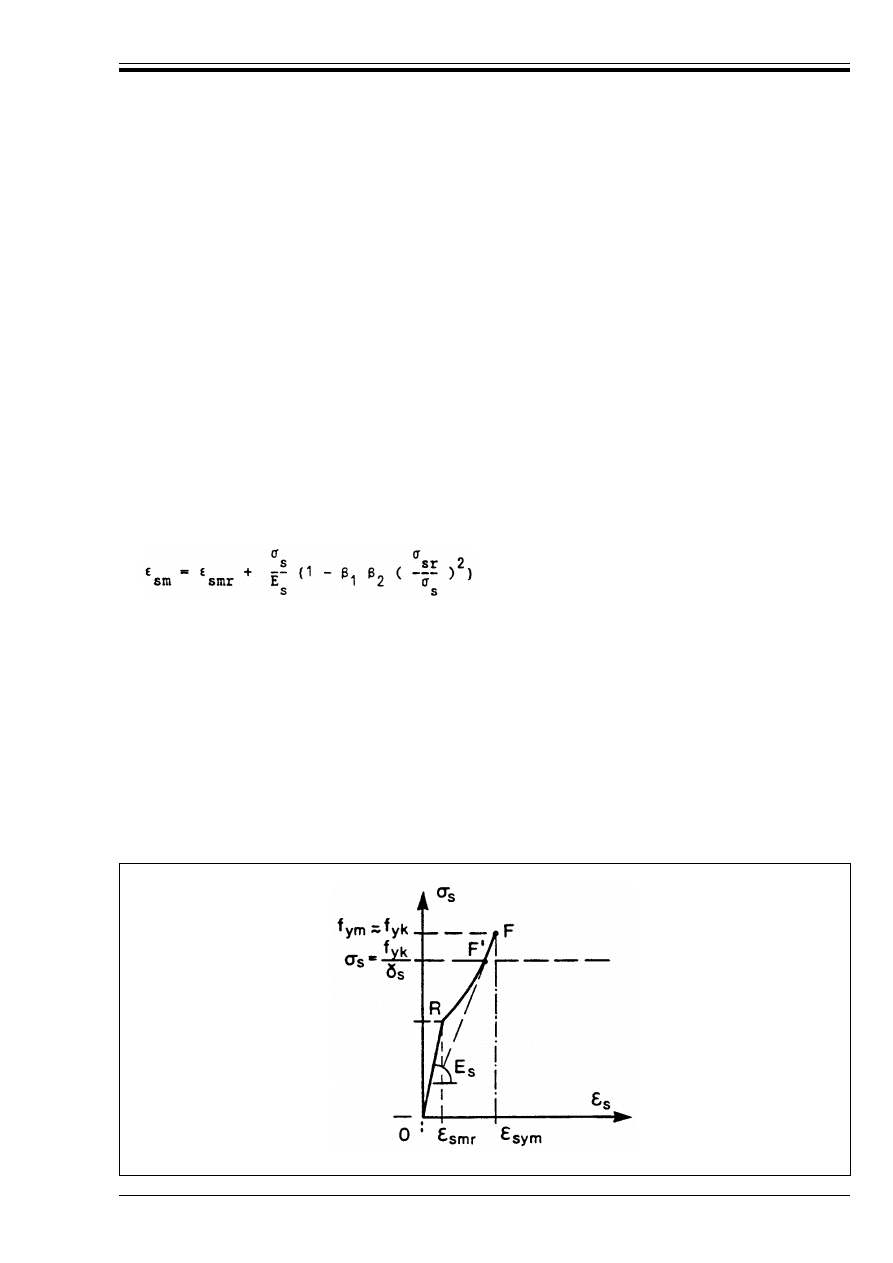
ENV 1992-1-1:1992
© BSI 12-1999
163
P(4) For structures dominantly subjected to static loads, the effects of previous applications of loading may
generally be ignored, and a monotonic increase of the intensity of the actions may be assumed.
A2.2 Refined approach for linear members subjected to bending with or without axial force
(1) Linear elements may be analysed by numerical methods which take, as their starting point, a design
moment-curvature relationship combined with the assumption that, on average, plane sections remain
plane.
As a simplification, the curvature may be derived from the relationship:
(2) The stress-strain relationships for concrete and steel should be as given in Sections 4.2.1, 4.2.2
and 4.2.3.
(3) The contribution of the concrete in tension between cracks (tension stiffening) may be taken into
account by the use of an effective average stress-strain curve for steel in cracked concrete. This may be
obtained from the equation below:
The relationship is valid between the cracking load, under which the maximum tensile stress in the
concrete reaches f
ctm
(see 3.1.2.3) and the load under which the reinforcement reaches yield.
Figure A2.1 illustrates the relationship.
(1/r)
m
= ((
sm
– (
c
)/d
(A2.1)
where:
(1/r)
m
is the average curvature at the section considered.
(
sm
is the average steel strain calculated taking account of tension stiffening
(
c
is the strain at the most compressed fibre (negative for compression) calculated
ignoring tension stiffening.
(A2.2)
where:
(
sm
is the average steel strain allowing for tension stiffening
(
smr
is the steel strain calculated on the basis of an uncracked section under the cracking load
B
sr
is the steel stress calculated on the basis of a cracked section under the cracking load
B
s
is the steel stress calculated on the basis of a cracked section under the loading considered.
"
1
is a coefficient which takes account of the bond properties of the reinforcement ("
1
= 1 for
deformed bars and 0.5 for plain bars)
"
2
is a coefficient which takes account of the duration and nature of the loading. ("
2
= 1 for short
term loading and 0.5 for long term or frequently repeated loading).
Figure A2.1 — Range of validity of Equation (A.2.2)
Licensed copy:Heriot Watt University, 20/04/2004, Uncontrolled Copy, © BSI
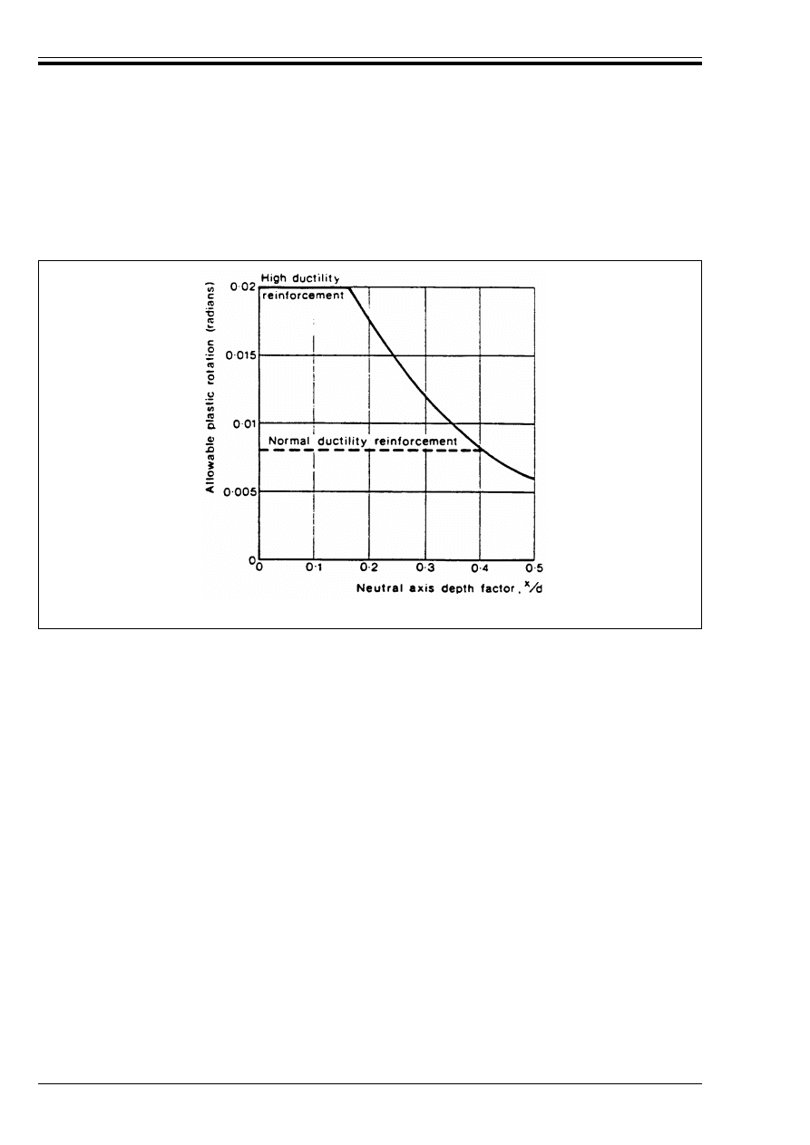
ENV 1992-1-1:1992
164
© BSI 12-1999
(4) Beyond the point corresponding to attainment of the design ultimate yield of the reinforcement (point
F½ in Figure A2.1), the section may be assumed to act as a plastic hinge carrying a constant moment
independent of curvature or rotation until a limiting plastic rotation, given in Figure A2.2, is reached. This
approach applies when the increase of moment beyond F½ is negligible. The effects of transverse steel are
neglected. The allowable plastic rotations given in Figure A2.2 take account of model uncertainty.
A2.3 Simplified methods (linear members)
(1) When calculating the rotation of plastic hinges by integration of the curvature between the hinges, it
will generally be sufficient to use a simplified linear moment-curvature diagram. This diagram may be
defined by a straight line from the origin to a point (1/r
m
, M
yk
) where M
yk
is the moment which produces
the stress f
yk
in the reinforcement, calculated on the basis of a cracked section and (1/r)
m
is the curvature
at the moment M
yk
calculated allowing for tension stiffening (1/r)
m
may be calculated from the relation:
(2) The limiting rotation given in Figure A2.2 may be assumed to apply at the moment M
yd
, corresponding
to the attainment of f
yd
at the hinge considered.
A2.4 Plastic analysis (linear members)
P(1) Methods of analysis involving plastic hinges without any direct check on their rotation capacity may
be used provided adequate ductility can be ensured and other factors such as model uncertainty are taken
into account.
(2) The rules given in 2.5.3.5.5 may be applied.
(3) Normal ductility steel should not be used unless its application can be justified.
A2.5 Non linear and plastic approaches for prestressed linear members
A2.5.1
Non linear methods
P(1) The internal forces and moments and the resistance shall be calculated taking account of the
non-linear behaviour of the prestressing and reinforcing steels and of the concrete.
Figure A2.2 — Allowable plastic rotation of reinforced concrete sections
(1/r)
m
= (1/r)
cr
(
sym
/(
sy
(A2.3)
where:
(1/r)
cr
is the curvature calculated on the basis of a cracked section
(
sy
is the yield strain of the reinforcement (= f
yk
/E
s
)
(
sym
is the strain calculated for B
s
= f
yk
= f
ym
allowing for tension stiffening.
Licensed copy:Heriot Watt University, 20/04/2004, Uncontrolled Copy, © BSI
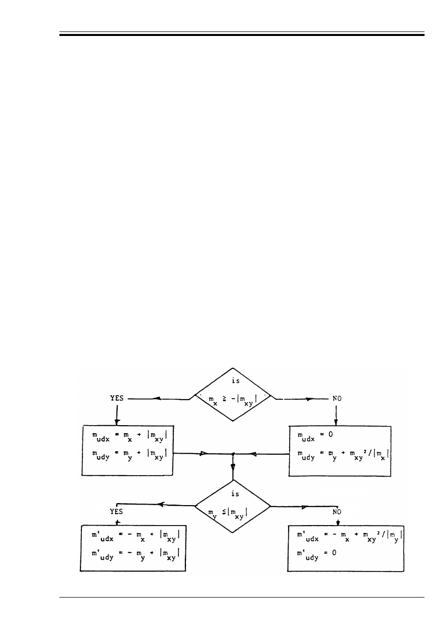
ENV 1992-1-1:1992
© BSI 12-1999
165
(2) As behaviour at the ultimate limit state is relatively insensitive to the effects of prestressing,
structural analysis may be carried out using *
p
= 1.
A2.5.2
Plastic methods
(1) A2.4(1) and (2) apply. The statically indeterminate effects of prestressing may be ignored in the design
of sections.
A2.6 Numerical methods of analysis for slabs
(1) In general the methods given in A2.2 may be adopted.
(2) When using non-linear numerical methods (e.g. Finite Element or Finite Difference methods) cracking
may be assumed to be either distributed or concentrated within orthotropic elements.
(3) The reinforcement in a slab analysed using numerical methods may be determined using the methods
given in A2.8 below.
A2.7 Non-linear analysis of walls and plates loaded in their own plane
(1) Non-linear analysis methods may be used for the ultimate and serviceability limit states using
deformation relationships based on material properties appropriate for the limit state considered. The
contribution of concrete in tension between cracks should be taken into account.
(2) Prior to analysis it is necessary to make a first estimate of a suitable arrangement and amount of
reinforcement. This may be done using the methods given in 2.5.3.6.3.
(3) The results of the analysis may be used to calculate appropriate areas of reinforcement by applying the
rules given in A2.8.
A2.8 Reinforcement in slabs
(1) The reinforcement in a slab subject to any general moment field may be assessed using the procedure
set out below.
(2) A set of orthogonal axes are chosen and the moments resolved in the directions of these axes to give
moments per unit length, m
x
, m
y
and m
xy
such that m
y
T m
x
. Reinforcement is provided in the x and y
directions to resist design ultimate moments, m
udx
, m½
udx
, m
udy
and m½
udy
, m
udx
and m
udy
are moments
giving tension in the bottom of the slab while m½
udx
and m½
udy
give tension in the top of the slab.
(3) The following flow chart is used to establish the values of the design ultimate moments from the values
of m
x
m
y
and m
xy
.
Licensed copy:Heriot Watt University, 20/04/2004, Uncontrolled Copy, © BSI
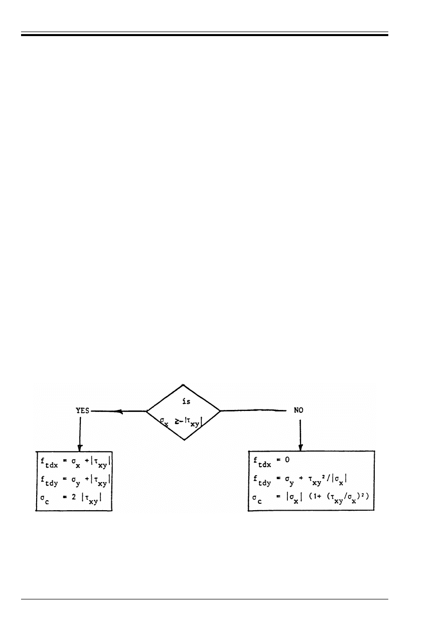
ENV 1992-1-1:1992
166
© BSI 12-1999
(4) As an alternative to (3) above, the required design moments may be obtained from Equations A2.4 to
A2.7 below:
* and *
½ are coefficients which should be chosen so that the equations give values which lie between half
and twice the values given by (3) above.
(5) The ability of a section to resist a given combination of moments will be satisfactory if the following
conditions are satisfied:
A2.9 Reinforcement in plates (walls)
(1) The reinforcement in an element of a plate subjected to a stress field defined by the stress B
x
, B
y
and
Ù
xy
, referred to an orthogonal co-ordinate system selected so that B
x
r B
y
may be calculated using the
procedure set out below.
(2) In the flow chart below, f
tdx
and f
tdy
are notional design tensile stresses in the material to be reinforced
in the x and y directions respectively. Assuming the tensile strength of the concrete to be zero, the
reinforcement ratios in the x and y direction are given as:
@
x
= f
tdx
/f
yd
; @
y
= f
tdy
/f
yd
(negative values should be taken as zero)
(3) For walls with reinforcement on both faces, which is properly anchored [e.g. by means of U-stirrups,
(see Figure 4.25)], the concrete stress B
c
should be limited to B
c
r f
cd
, while at the same time limiting the
shear stress to:
m
udx
= m
x
+ *||m
xy
|
(A2.4)
m
udy
= m
y
+ 1/*||m
xy
|
(A2.5)
m½
udx
= – m
x
+ *½|m
xy
|
(A2.6)
m½
udx
= – m
x
+ 1/*½|m
xy
|
(A2.7)
– (m
udx
– m
x
) (m
udy
– m
y
) + m
xy
2
r 0
(A2.8)
– (m½
udx
+ m
x
) (m½
udy
+ m
y
) + m
xy
2
r 0
(A2.9)
m
x
r m
udx
(A2.10)
m
y
r m
udy
(A2.11)
m
x
T – m½
udx
(A2.12)
m
y
T – m½
udy
(A2.13)
|Ù
xy
| r 1/2 5 f
cd
(A2.14a)
when 5 is determined by Equation (4.21).
Other values of 5 may be used, if appropriately defined by tests.
Licensed copy:Heriot Watt University, 20/04/2004, Uncontrolled Copy, © BSI

ENV 1992-1-1:1992
© BSI 12-1999
167
(4) As an alternative to the procedure given in (2) above, the reinforcement may be estimated from
Equations A2.15 and A2.16 below:
The coefficient * should be chosen so that the results from Equations A2.15 and A2.16 lie between one half
and twice the values given by (2) above.
The stress in the concrete is given by:
(5) The ability of a section to resist a given combination of stresses will be satisfactory if the following
conditions are met:
Appendix 3 Supplementary information on the ultimate limit states induced by
structural deformations
A3.0 Notation (See also 1.6 and 1.7)
A3.1 Design procedures
P(1) The combinations of actions and the safety factors given in 2.3 shall normally be used. However, in
multi-storey buildings,
11)
lower safety factors *
F
than those given in 2.3 may be used for the calculation of
structural deformations which lead to second order effects. This applies in particular for the calculation of
creep deformations.
P(2) For some applications, the design format defined in 2.2.2.5 may be used.
P(3) In multi-storey buildings,
1)
the deformations of the structure may be calculated by using a reduced
safety coefficient *
c
for concrete.
In the absence of appropriate test data, the shear stress should be limited to:
|Ù
xy
|r f
cd
/ßf
ck
(A2.14b)
(f
ck
in N/mm
2
)
f
tdx
= B
x
+ * ||Ù
xy
|
(A2.15)
f
tdy
= B
y
+ 1/*||Ù
xy
||
(A2.16)
B
c
= |Ù
xy
| (* + 1/*)
(A2.17)
– (f
tdx
– B
x
) (f
tdy
– B
y
) + Ù
xy
2
r 0
(A2.18)
– (f
cd
– B
x
) (f
cd
– B
y
) (f
cd
– B
y
) + Ù
xy
2
r 0
(A2.19)
|Ù
xy
|r 1/2 5 f
cd
(A2.20)
B
x
r f
tdx
B
y
r f
tdy
(A2.21)
B
x
T – f
cd
B
y
T – f
cd
(A2.22)
F
5
Sum of all vertical loads under service conditions
f
ctk, 0.05
Lower characteristic value of tensile strength of concrete
h
tot
Total height of structure from top surface of foundation or non-deformable sub-stratum (in
metres)
M
Sd1
First order design moment
n
Number of storeys
N
Sd,m
Mean axial design force in columns in one storey
2
m
Mean slenderness ratio of columns within storey considered
5
u
Longitudinal force coefficient for a member
11)
In the absence of national regulations, buildings may be considered multistorey, if their total height above ground exceeds
|22| m.
Licensed copy:Heriot Watt University, 20/04/2004, Uncontrolled Copy, © BSI

ENV 1992-1-1:1992
168
© BSI 12-1999
(4) The partial safety factors *
F
given in 2.3 may be reduced by about |10 %| for multi-storey buildings.
(5) In multi-storey buildings, where a refined analysis of creep deformation is necessary [see A3.4 P(3)
and (8)], the following safety coefficients *
F
for quasi-permanent loading are recommended:
(6) A reduced safety coefficient *
c
= |1.35| may be used in the analysis of frame structures by the general
method (see 4.3.5.2).
(7) When applying 4.3.5 a refined general method or an appropriate proven simplified method may be
used.
These methods may be classified as follows:
— General methods: Non-linear analyses using appropriate design models of the structure.
— Simplified methods: These may be either:
a) approximate non-linear second order analyses, simplified by assuming a distribution of the internal
forces and moments and/or a deformed shape of the structure; or,
b) first order analyses of cross-sections at the ultimate limit state for bending and longitudinal force
modified by multiplying the first order internal forces and moments N
Sd
and/or M
Sd1
by coefficients
to cover the increase of M
Sd1
due to deformations.
Simplified methods may be based on the real structure (e.g. height of columns between centres of
restraints) or on fictitious design models (e.g. Model column, see 4.3.5.6.3).
Appropriate design aids may be used.
(8) It is generally necessary to check the critical cross section about each of the two principle axes. For
these two directions, different restraint conditions may be present at the ends of the member. These
conditions should be represented in an adequate way.
P(9) The influence of the soil behaviour on the stability of a structure shall be considered and, if significant,
taken into account in the design calculations.
(10) The design procedures envisaged in 4.3.5 are illustrated in the flow charts in Figure A3.1,
Figure A3.2 and Figure A3.3 below.
|*
F
= 1.1| : for statically indeterminate structures
|*
F
= 1.2| : for statically determinate structures and structural elements.
Licensed copy:Heriot Watt University, 20/04/2004, Uncontrolled Copy, © BSI
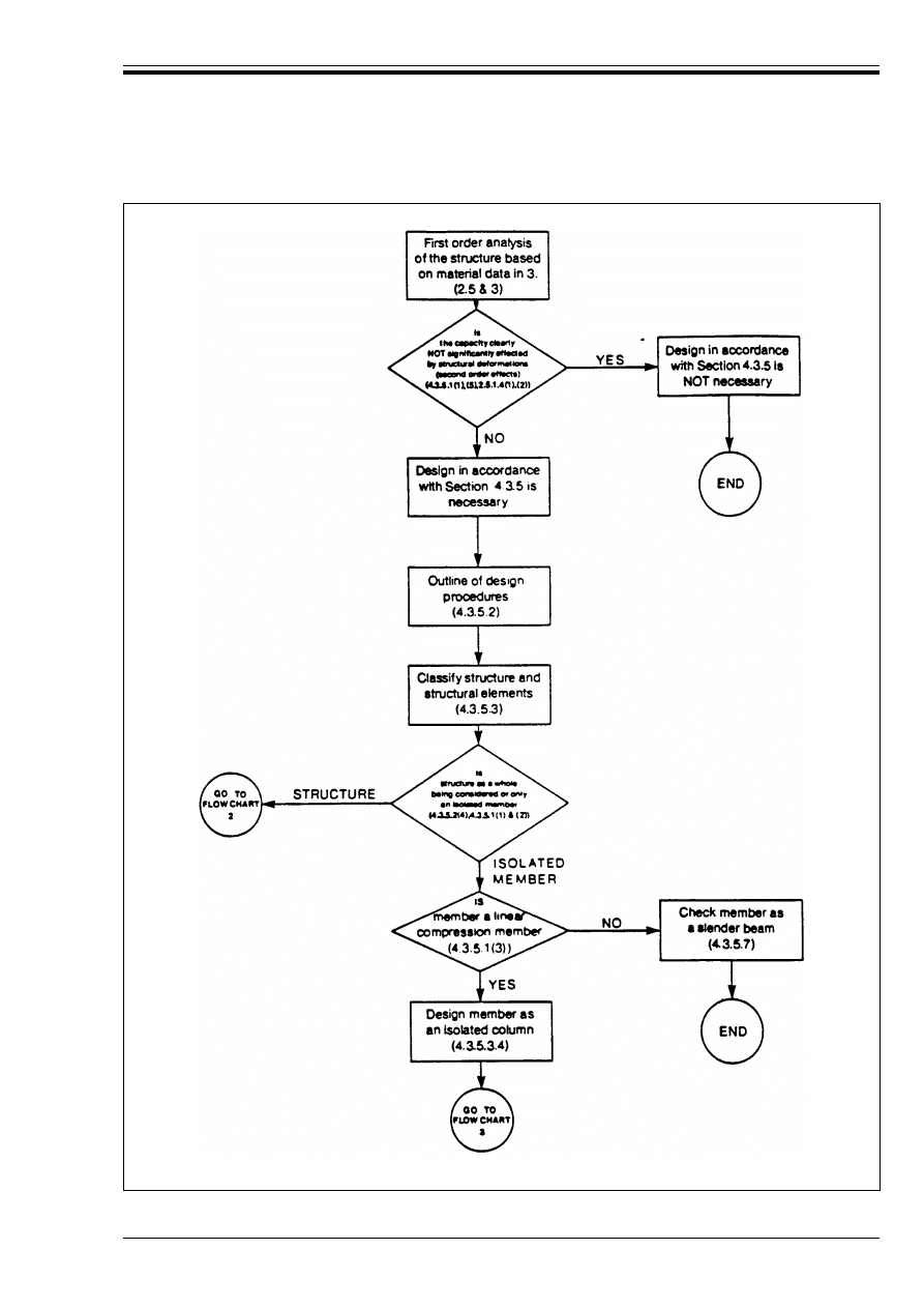
ENV 1992-1-1:1992
© BSI 12-1999
169
Figure A3.1 — Flow Chart 1: General guide to application of section 4.3.5
Licensed copy:Heriot Watt University, 20/04/2004, Uncontrolled Copy, © BSI
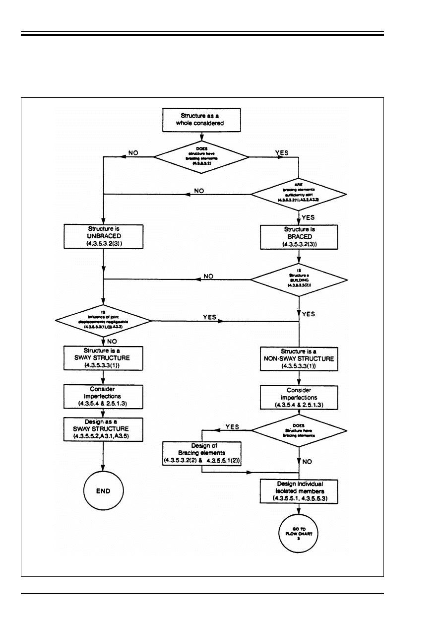
ENV 1992-1-1:1992
170
© BSI 12-1999
Figure A3.2 — Flow Chart 2: Application of provisions of 4.3.5 and A3 to ultimate
limit states due to deformation of the structure as a whole
Licensed copy:Heriot Watt University, 20/04/2004, Uncontrolled Copy, © BSI
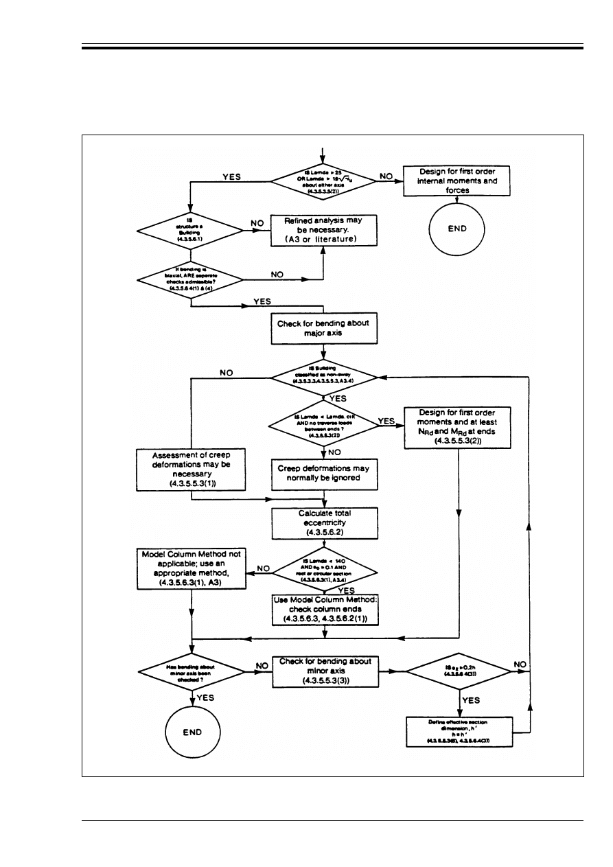
ENV 1992-1-1:1992
© BSI 12-1999
171
Figure A3.3 — Flow Chart: 3 Design procedures for isolated columns
Licensed copy:Heriot Watt University, 20/04/2004, Uncontrolled Copy, © BSI

ENV 1992-1-1:1992
172
© BSI 12-1999
A3.2 Non-sway structures
(1) Provided that the bracing elements are reasonably symmetrically distributed within the building,
braced frames can be classified as non-sway if the flexural stiffness of the bracing elements satisfies the
criterion below:Provided that the bracing elements are reasonably symmetrically distributed within the
building, braced frames can be classified as non-sway if the flexural stiffness of the bracing elements
satisfies the criterion below:
It should be noted chat there are cases where the above equations will be conservative.
(2) If Equation (A3.1) or (A3.2) is not satisfied, the structure is classified as sway and should be designed
accordingly.
(3) Frames without bracing elements may be considered non-sway structures if each vertical element of
the frame which resists more than |70 %| of the mean axial force N
Sd,m
= *
F
.F
v
/n (n denotes the number
of vertical elements in one storey) has a slenderness ratio 2 less than or equal to the greater of 25
or 15ß5
u
(See Figure A3.4).
A3.3 Bracing elements in braced structures
(1) In addition to 4.3.5.3.2(1) and in order to avoid horizontal forces in the braced sub-assembly
(e.g. columns), bracing elements should be designed to resist all horizontal loads acting on the structure
(i.e. 100 %).
A3.4 Specific data
P(1) A stress-strain diagram for concrete shall be used which adequately represents the real behaviour.
P(2) The contribution of the tensile strength of the concrete between cracks (tension stiffening) shall, if not
stated otherwise, be taken into account.
P(3) Creep effects shall be considered if they are likely to reduce the structural stability significantly.
P(4) The same stress-strain diagram for steel as used for cross-section design shall be adopted
(see 4.2.2.3.2).
P(5) Plane sections shall be assumed to remain plane as stated in 4.3.1.2.
(6) For the concrete, the stress-strain diagram given in section 4.2.1.3.3 a) should be used with f
c
and E
c
taken as:
(7) It will always be conservative to ignore tension stiffening effects. However, when using the model
column method (see 4.3.5.6.3), the contribution of tension stiffening should not be taken into account.
for n r 3: h
tot
. ß(F
v
/E
cm
I
c
) r 0.2 + 0.1 n
(A3.1)
for n T 4: h
tot
. ß(F
v
/E
cm
I
c
) r 0.6
(A3.2)
where:
n
is the number of storeys
h
tot
is the total height of the structure in metres measured from the top surface of the foundation or
from a non-deformable sub-stratum;
E
cm
I
c
is the sum of the nominal flexural stiffnesses of all the vertical bracing elements as defined
in 4.3.5.3.2(1) acting in the direction under consideration. In the bracing elements, the concrete
tensile stress under the relevant load combination in service conditions should not exceed the
value f
ctk,0.05
defined in 3.1.2.3. If the stiffness of the bracing elements varies over their height,
an equivalent stiffness should be used;
F
5
is the sum of all vertical loads (i.e. acting both on the bracing elements and the braced
sub-assembly) under service conditions, (i.e. *
F
= 1).
f
c
= f
cd
= f
ck
/*
c
(A.3.3)
E
c
= E
cd
= E
cm
/*
c
;
For the safety factor *
c
, A3.1, P(3) and (6), apply.
Licensed copy:Heriot Watt University, 20/04/2004, Uncontrolled Copy, © BSI
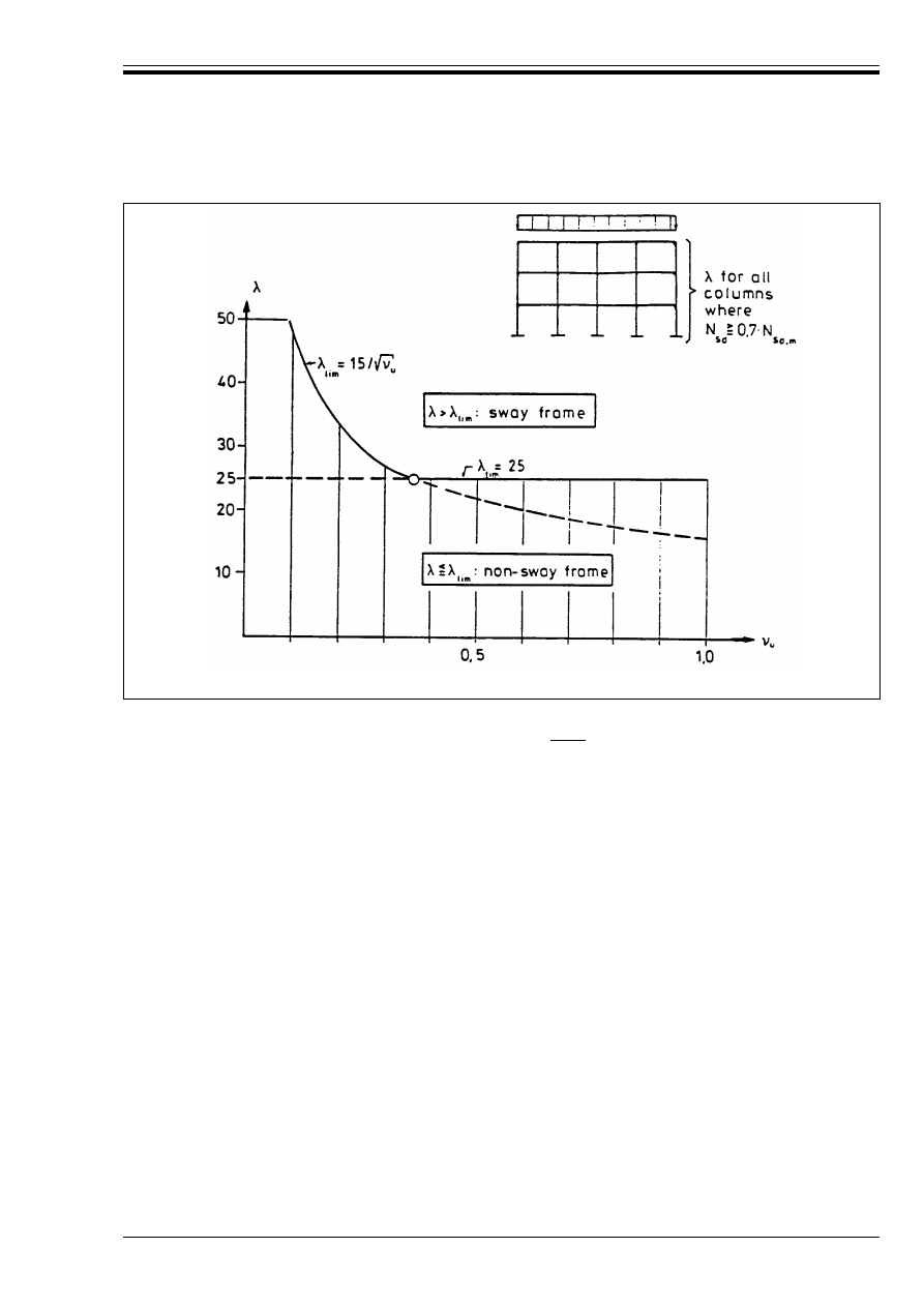
ENV 1992-1-1:1992
© BSI 12-1999
173
(8) For simplification, creep effects may be ignored if the increase in the first order bending moments due
to creep deformations and longitudinal force do not exceed |10 %|. Where necessary, creep effects may be
assessed by means of approximate methods based on 2.5.5 or, alternatively, by a modification of the
stress-strain relationship for the concrete or by a correction of the additional eccentricity or unintentional
inclination defined in 2.5.1.
The safety coefficients given in A3.1 should be used for the calculation of creep deformations, unless
stated otherwise.
(9) In non-away buildings, creep deformations of slender compression members connected monolithically
to slabs or beams at their two ends may normally be disregarded because their effects are generally
compensated by other influences which are neglected in the design. In interior columns, the restraints at
the column ends reduce the creep deformations significantly so that they can be neglected. In edge
columns with different eccentricities at each end, creep increases the deformations but it does not
decrease the bearing capacity because these deformations are not additional to the critical column
deflections in the relevant failure state.
A3.5 Sway frames
P(1) Sway frames shall be designed using the design data given in 4.3.5.4 and A3.4. Equivalent
geometrical imperfections and, if necessary for reasons of structural stability, creep deformations shall be
taken into account.
(2) The simplified methods defined in 4.3.5 may be used instead of a refined analysis, provided that the
safety level required is ensured.
(3) For regular frames, simplified methods may be used which introduce, for example, increased
horizontal design loads or bending moments which take account of second order effects in addition to the
effects of geometrical imperfections. Regular frames are, for example, frames formed by beams and
columns which have approximately equal nominal stiffnesses and a mean slenderness ratio 2
m
of each
storey which is less than or equal to:
Figure A3.4 — Slenderness limits in frames (A3.2)
50 or 20/ß5
u
(A.3.4)
Licensed copy:Heriot Watt University, 20/04/2004, Uncontrolled Copy, © BSI

ENV 1992-1-1:1992
174
© BSI 12-1999
(4) If the mean slenderness ratio, 2
m
, is greater than the value given by Equation (A3.4), reference should
be made to appropriate literature to conform with P(1) and (2) above.
Appendix 4 Checking deflections by calculation
A4.0 Symbols (see also 1.6 and 1.7)
A4.1 General
P(1) This Appendix sets out the procedures to be adopted when calculating deformations and describes a
simplified calculation method suitable for use in the design of members such as frames, beams or slabs.
P(2) The deformation of reinforced and prestressed concrete members is influenced by a great many factors,
none of which are known with certainty. The calculated result is not regarded as an accurate prediction of
the deflection which will be expected to occur. For this reason, the use of excessively sophisticated
calculation methods is avoided.
A4.2 Requirements for the calculation of deformations
P(1) The calculation method adopted shall represent the true behaviour of the structure to an accuracy
appropriate to the objectives of the calculation. In particular, where elements are expected to be cracked,
the influence of the cracks on the deformations of the tension chord and of the corresponding compression
chord shall be taken into account.
P(2) Where appropriate, the following shall be considered:
— Effects of creep and shrinkage
— Stiffening effect of the concrete in tension between the cracks.
— Cracking resulting from previous loadings
— The influence of indirect actions such as temperature
— Type of loading: static or dynamic
— The appropriate value of modulus of elasticity of the concrete, taking account of the aggregate type
and maturity at time of loading.
whichever is greater.
where:
2
m
is the mean slenderness ratio of all columns within the storey considered (see 4.3.5.3.5).
5
u
= N
Sd
/A
c
· f
cd
E
c,eff
Effective modulus of elasticity of concrete
M
cr
Moment causing cracking
N
cr
Axial force causing cracking
1/r
cs
Curvature due to shrinkage
S
First moment of area of the reinforcement about the centroid of the section
!
A deformation parameter (may be a strain, deflection, curvature or rotation)
!
I
Value of ! calculated assuming an uncracked section
!
II
Value of ! calculated assuming a fully cracked section
!
e
Modular ratio (= E
s
/E
c
.
ef
)
"
1
A coefficient taking account of the bond properties of reinforcement
"
2
A coefficient taking account of the nature and duration of loading
(
cs
Free shrinkage strain
M
Distribution coefficient
B
s
Stress in tension steel calculated on the basis of a cracked section
B
sr
Stress in tension steel calculated on the basis of a cracked section under the loading which
will just cause cracking
Ì
Creep coefficient
Licensed copy:Heriot Watt University, 20/04/2004, Uncontrolled Copy, © BSI
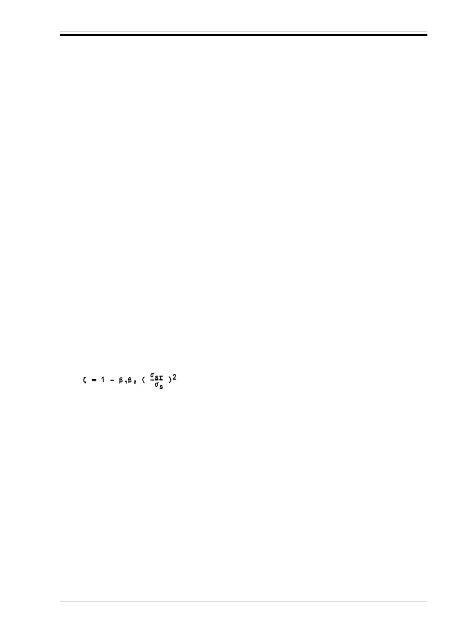
ENV 1992-1-1:1992
© BSI 12-1999
175
P(3) It should be noted that, if cracking is expected under the actions considered, the principle of
superposition is invalid for the calculation of deformations.
(4) Simplified methods may be used provided their degree of approximation is acceptable in the particular
case considered.
(5) In buildings, it will normally be satisfactory to consider the deflections under the quasi-permanent
combination of loading and assuming this load to be of long duration.
(6) It may occasionally be necessary to take into account deformations from causes other than flexure, for
example shear or torsional deformations, or differential contraction of vertical members in tall buildings.
These possibilities will not, however, be covered further in this code.
A4.3 Calculation method
(1) Two limiting conditions are assumed to exist for the deformation of concrete sections.
— the uncracked condition.
In this state, steel and concrete act together elastically in both tension and compression.
— the fully cracked condition.
In this state, the influence of the concrete in tension is ignored.
(2) Members which are not expected to be loaded above the level which would cause the tensile strength of
the concrete to be exceeded anywhere within the member will be considered to be uncracked. Members
which are expected to crack will behave in a manner intermediate between the uncracked and fully cracked
conditions and, for members subjected dominantly to flexure, an adequate prediction of behaviour is given
by Equation (A4.1) below.
The critical material properties required to enable deformations due to loading to be assessed are the
tensile strength and the effective modulus of elasticity of the concrete.
Table 3.1 indicates the range of likely values for tensile strength. In general, a best estimate of the
behaviour will be obtained if f
ctm
is used.
! = M!
II
+ (1 – M)!
I
(A.4.1)
where
!
is the parameter considered which may be, for example, a strain, a curvature, or a rotation. (As a
simplification, ! may also be taken as a deflection — see (3) below)
!
I
and !
II
are, respectively, the values of the parameter calculated for the uncracked and fully cracked
conditions.
NM
is a distribution coefficient given by Equation (A4.2) below:
(A4.2)
"
1
is a coefficient which takes account of the bond properties of the bars
= 1 for high bond bars
= 0.5 for plain bars.
"
2
is a coefficient which takes account of the duration of the loading or of repeated loading
= 1 for a single short-term loading
= 0.5 for sustained loads or many cycles of repeated loading
B
s
is the stress in the tension steel calculated on the basis of a cracked section.
B
sr
is the stress in the tension steel calculated on the basis of a cracked section under the loading
which will just cause cracking at the section being considered.
(Note: B
s
/B
sr
can be replaced by M/Mcr for flexure or N/Ncr for pure tension).
M
is zero for uncracked sections.
Licensed copy:Heriot Watt University, 20/04/2004, Uncontrolled Copy, © BSI

ENV 1992-1-1:1992
176
© BSI 12-1999
An estimate of the modulus of elasticity of the concrete may be obtained from Table 3.2. Creep may be
allowed for by using an effective modulus calculated from Equation (A4.3):
S and I should be calculated for the uncracked condition and the fully cracked condition, the final curvature
being assessed by use of Equation (A4.1).
(3) The most rigorous method of assessing deflections using the method given in (2) above is to compute the
curvatures at frequent sections along the member and then calculate the deflection by numerical
integration. The effort involved in this is not normally justified and it will be acceptable to compute the
deflection twice assuming the whole member to be in the uncracked and fully cracked condition in turn and
then employ Equation (A4.1). The approach given in a) above is not directly applicable to cracked sections
subjected to significant normal force.
E
c,eff
= E
cm
/(1 + Ì)
(A4.3)
where
Ì is the creep coefficient (see Table 3.3)
Shrinkage curvatures may be assessed by using Equation (A4.4)
1/r
cs
= (
cs
!
e
S/I
(A4.4)
where
1/r
cs
is the curvature due to shrinkage
(
cs
is the free shrinkage strain (see Table 3.4)
S
is the first moment of area of the reinforcement about the centroid of the section
I
is the second moment of area of the section
!
e
is the effective modular ratio = E
s
/E
c,ef
Licensed copy:Heriot Watt University, 20/04/2004, Uncontrolled Copy, © BSI

DD ENV 1992-1-1:1992
© BSI 12-1999
National annex NA (informative)
Committees responsible
The preparation of the National Application Document for use in the UK with ENV 1992-1-1:1992 was
entrusted by Technical Committee B/525, Building and civil engineering structures, to Subcommittee
B/525/2, Structural use of concrete upon which the following bodies were represented:
Association of Consulting Engineers
British Cement Association
British Precast Concrete Federation Ltd.
Concrete Society
Department of the Environment (Building Research Establishment)
Department of the Environment (Construction Directorate)
Department of the Environment (Property Services Agency)
Department of Transport
Federation of Civil Engineering Contractors
Institution of Civil Engineers
Institution of Structural Engineers
Steel Reinforcement Commission
Licensed copy:Heriot Watt University, 20/04/2004, Uncontrolled Copy, © BSI
DD ENV
1992-1-1:1992
BSI
389 Chiswick High Road
London
W4 4AL
BSI — British Standards Institution
BSI is the independent national body responsible for preparing
British Standards. It presents the UK view on standards in Europe and at the
international level. It is incorporated by Royal Charter.
Revisions
British Standards are updated by amendment or revision. Users of
British Standards should make sure that they possess the latest amendments or
editions.
It is the constant aim of BSI to improve the quality of our products and services.
We would be grateful if anyone finding an inaccuracy or ambiguity while using
this British Standard would inform the Secretary of the technical committee
responsible, the identity of which can be found on the inside front cover.
Tel: 020 8996 9000. Fax: 020 8996 7400.
BSI offers members an individual updating service called PLUS which ensures
that subscribers automatically receive the latest editions of standards.
Buying standards
Orders for all BSI, international and foreign standards publications should be
addressed to Customer Services. Tel: 020 8996 9001. Fax: 020 8996 7001.
In response to orders for international standards, it is BSI policy to supply the
BSI implementation of those that have been published as British Standards,
unless otherwise requested.
Information on standards
BSI provides a wide range of information on national, European and
international standards through its Library and its Technical Help to Exporters
Service. Various BSI electronic information services are also available which give
details on all its products and services. Contact the Information Centre.
Tel: 020 8996 7111. Fax: 020 8996 7048.
Subscribing members of BSI are kept up to date with standards developments
and receive substantial discounts on the purchase price of standards. For details
of these and other benefits contact Membership Administration.
Tel: 020 8996 7002. Fax: 020 8996 7001.
Copyright
Copyright subsists in all BSI publications. BSI also holds the copyright, in the
UK, of the publications of the international standardization bodies. Except as
permitted under the Copyright, Designs and Patents Act 1988 no extract may be
reproduced, stored in a retrieval system or transmitted in any form or by any
means – electronic, photocopying, recording or otherwise – without prior written
permission from BSI.
This does not preclude the free use, in the course of implementing the standard,
of necessary details such as symbols, and size, type or grade designations. If these
details are to be used for any other purpose than implementation then the prior
written permission of BSI must be obtained.
If permission is granted, the terms may include royalty payments or a licensing
agreement. Details and advice can be obtained from the Copyright Manager.
Tel: 020 8996 7070.
Licensed copy:Heriot Watt University, 20/04/2004, Uncontrolled Copy, © BSI
Document Outline
Wyszukiwarka
Podobne podstrony:
Eurocode 2 Design of concrete structures Part 2
Eurocode 2 Design of concrete structures Part 1 3
Eurocode 2 Design of concrete structures Part 2
Eurocode 2 Design of concrete structures part1 2
Eurocode 2 Design of concrete structures part4
Eurocode 2 Design of concrete structures part4
Eurocode 2 Part 3 2006 UK NA Design of concrete structures Liquid retaining and containing struc
Eurocode 2 Part 1 1 2004 NA UK Design of concrete structures General rules and rules for buildin
Eurocode 2 Part 3 2006 Design of concrete structures Liquid retaining and containing structures
Eurocode 2 Part 2 2004 UK NA Design of concrete structures Concrete bridges Design and detailin
Eurocode 5 EN 1995 1 1 Design Of Timber Structures Part 1 1 General Rules
Eurocode 5 EN 1995 1 1 Design Of Timber Structures Part 1 1 General Rules
Eurocode 6 Part 1 2 1996 2005 Design of Masonry Structures General Rules Structural Fire Design
Eurocode 6 Part 2 1996 2006 Design of Masonry Structures Design Considerations, Selection of Mat
Eurocode 3 Part 1 7 2009 Design of Steel Structures Plated Structures Subject to Out of Plane Loa
więcej podobnych podstron