
RSI_Rel. 2.0 10.02.01 en
1 of 46
SOFTWARE
KR C...
Robot Sensor Interface (RSI)
Release 2.0

2 of 46
RSI_Rel. 2.0 10.02.01 en
e
Copyright
KUKA Roboter GmbH
This documentation or excerpts therefrom may not be reproduced or disclosed to third parties without the express permission of the publishers.
Other functions not described in this documentation may be operable in the controller. The user has no claim to these functions, however, in
the case of a replacement or service work.
We have checked the content of this documentation for conformity with the hardware and software described. Nevertheless, discrepancies
cannot be precluded, for which reason we are not able to guarantee total conformity. The information in this documentation is checked on a
regular basis, however, and necessary corrections will be incorporated in subsequent editions.
Subject to technical alterations without an effect on the function.
PD Interleaf

3 of 46
RSI_Rel. 2.0 10.02.01 en
Contents
1
Characteristics, program installation
5
. . . . . . . . . . . . . . . . . . . . . . . . . . . . . .
1.1
Characteristics
5
. . . . . . . . . . . . . . . . . . . . . . . . . . . . . . . . . . . . . . . . . . . . . . . . . . . . . . . . . . . . . . . .
1.2
Installation / uninstallation / update
6
. . . . . . . . . . . . . . . . . . . . . . . . . . . . . . . . . . . . . . . . . . . . . . .
2
Program description
7
. . . . . . . . . . . . . . . . . . . . . . . . . . . . . . . . . . . . . . . . . . . . .
2.1
Structure of the RSI program
7
. . . . . . . . . . . . . . . . . . . . . . . . . . . . . . . . . . . . . . . . . . . . . . . . . . . .
2.2
Method of operation of RSI
7
. . . . . . . . . . . . . . . . . . . . . . . . . . . . . . . . . . . . . . . . . . . . . . . . . . . . . .
2.3
RSI objects
8
. . . . . . . . . . . . . . . . . . . . . . . . . . . . . . . . . . . . . . . . . . . . . . . . . . . . . . . . . . . . . . . . . . .
2.3.1
Object components
8
. . . . . . . . . . . . . . . . . . . . . . . . . . . . . . . . . . . . . . . . . . . . . . . . . . . . . . . . . . . .
2.3.1.1 Structure
8
. . . . . . . . . . . . . . . . . . . . . . . . . . . . . . . . . . . . . . . . . . . . . . . . . . . . . . . . . . . . . . . . . . . . .
2.3.1.2 RSI units
9
. . . . . . . . . . . . . . . . . . . . . . . . . . . . . . . . . . . . . . . . . . . . . . . . . . . . . . . . . . . . . . . . . . . . .
2.3.2
Creating objects
10
. . . . . . . . . . . . . . . . . . . . . . . . . . . . . . . . . . . . . . . . . . . . . . . . . . . . . . . . . . . . . . .
2.3.3
Linking objects
11
. . . . . . . . . . . . . . . . . . . . . . . . . . . . . . . . . . . . . . . . . . . . . . . . . . . . . . . . . . . . . . . .
2.3.4
Containers
12
. . . . . . . . . . . . . . . . . . . . . . . . . . . . . . . . . . . . . . . . . . . . . . . . . . . . . . . . . . . . . . . . . . . .
2.3.5
Changing object parameters
13
. . . . . . . . . . . . . . . . . . . . . . . . . . . . . . . . . . . . . . . . . . . . . . . . . . . . .
2.3.6
Debugging
14
. . . . . . . . . . . . . . . . . . . . . . . . . . . . . . . . . . . . . . . . . . . . . . . . . . . . . . . . . . . . . . . . . . . .
2.3.6.1 Log file
14
. . . . . . . . . . . . . . . . . . . . . . . . . . . . . . . . . . . . . . . . . . . . . . . . . . . . . . . . . . . . . . . . . . . . . . .
2.3.6.2 Error messages
14
. . . . . . . . . . . . . . . . . . . . . . . . . . . . . . . . . . . . . . . . . . . . . . . . . . . . . . . . . . . . . . . .
2.4
Structure of a sensor application
16
. . . . . . . . . . . . . . . . . . . . . . . . . . . . . . . . . . . . . . . . . . . . . . . . .
2.5
Program example
18
. . . . . . . . . . . . . . . . . . . . . . . . . . . . . . . . . . . . . . . . . . . . . . . . . . . . . . . . . . . . . .
3
RSI commands
21
. . . . . . . . . . . . . . . . . . . . . . . . . . . . . . . . . . . . . . . . . . . . . . . . . .
3.1
Structure of command descriptions
21
. . . . . . . . . . . . . . . . . . . . . . . . . . . . . . . . . . . . . . . . . . . . . . .
3.2
General commands
22
. . . . . . . . . . . . . . . . . . . . . . . . . . . . . . . . . . . . . . . . . . . . . . . . . . . . . . . . . . . .
3.3
Link commands
25
. . . . . . . . . . . . . . . . . . . . . . . . . . . . . . . . . . . . . . . . . . . . . . . . . . . . . . . . . . . . . . . .
3.4
Motion commands
26
. . . . . . . . . . . . . . . . . . . . . . . . . . . . . . . . . . . . . . . . . . . . . . . . . . . . . . . . . . . . .
3.5
RSI objects
28
. . . . . . . . . . . . . . . . . . . . . . . . . . . . . . . . . . . . . . . . . . . . . . . . . . . . . . . . . . . . . . . . . . .
3.5.1
Data objects
28
. . . . . . . . . . . . . . . . . . . . . . . . . . . . . . . . . . . . . . . . . . . . . . . . . . . . . . . . . . . . . . . . . . .
3.5.2
Signal processing objects
32
. . . . . . . . . . . . . . . . . . . . . . . . . . . . . . . . . . . . . . . . . . . . . . . . . . . . . . .
3.5.2.1 Transformations
32
. . . . . . . . . . . . . . . . . . . . . . . . . . . . . . . . . . . . . . . . . . . . . . . . . . . . . . . . . . . . . . .
3.5.2.2 Logical operations
38
. . . . . . . . . . . . . . . . . . . . . . . . . . . . . . . . . . . . . . . . . . . . . . . . . . . . . . . . . . . . . .
3.5.2.3 Comparison operations
40
. . . . . . . . . . . . . . . . . . . . . . . . . . . . . . . . . . . . . . . . . . . . . . . . . . . . . . . . .
3.5.2.4 Control objects
41
. . . . . . . . . . . . . . . . . . . . . . . . . . . . . . . . . . . . . . . . . . . . . . . . . . . . . . . . . . . . . . . .
3.5.2.5 Additional signal processing objects
44
. . . . . . . . . . . . . . . . . . . . . . . . . . . . . . . . . . . . . . . . . . . . . .
3.5.2.6 Action objects
44
. . . . . . . . . . . . . . . . . . . . . . . . . . . . . . . . . . . . . . . . . . . . . . . . . . . . . . . . . . . . . . . . .
3.6
Other objects
46
. . . . . . . . . . . . . . . . . . . . . . . . . . . . . . . . . . . . . . . . . . . . . . . . . . . . . . . . . . . . . . . . . .

Robot Sensor Interface (RSI)
4 of 46
RSI_Rel. 2.0 10.02.01 en

1
Characteristics, program installation
5 of 46
RSI_Rel. 2.0 10.02.01 en
1
Characteristics, program installation
The Robot Sensor Interface (RSI) makes it possible to create sensor applications in the
programming language KRL (KUKA Robot Language). It contains a library of standard
functions for sensor applications, such as filters, transformations, control functions, etc.
RSI is object--oriented, modularly structured, and provides a special set of commands for
standard applications.
The program Robot Sensor Interface (RSI) can be used with the following software:
KR C1 Release 4.0 and 4.1, or
KR C2 Release 4.0, 4.1 and 5.1.
1.1
Characteristics
The Robot Sensor Interface (RSI) is an open system with maximum flexibility. This program
makes it possible to integrate any sensor into the KUKA robot controller, and its flexible object
linking means that it can be adapted or expanded to accommodate practically any type of
new sensor. RSI allows quick, easily--managed development of sensor applications.
RSI is object--oriented. This means that no commands are processed; instead, RSI
commands are used to create objects and change their characteristics. Once the objects
have been created and activated, they are then evaluated continuously in parallel with a
running program.
RSI is modularly structured, and is integrated into KRL. The application itself is implemented
in KRL. New solutions and expansions can be developed from existing components. The
range of functions (commands, supported sensors, etc.) is expandable in the form of
libraries.
RSI provides a set of commands for standard applications, for example functions for velocity
and position control, transformations, comparison operations, etc.
The sensor data are evaluated in parallel with a running program, thus making it possible to
monitor the motion sequences. Program creation is largely independent of the sensor being
used and is based on the “object libraries” principle. Complex applications with many different
sensors can be implemented by working with a number of different libraries simultaneously.
Object--independent RSI commands make it possible to standardize the development of
various applications.

Robot Sensor Interface (RSI)
6 of 46
RSI_Rel. 2.0 10.02.01 en
1.2
Installation / uninstallation / update
Technology packages are offered exclusively as add--on software modules.
The installation procedure is the same for all technology packages and is described in
separate documentation module.
The installation, uninstallation, reinstallation and update of technology
packages are described in detail in the documentation “Installation/Uninstalla-
tion/Update of Tech Packages”.
2
Program description
7 of 46
RSI_Rel. 2.0 10.02.01 en
2
Program description
2.1
Structure of the RSI program
RSI provides a uniform interface for various sensor applications. Unlike the usual case,
where the sensor system is connected via external interfaces, here the sensor is integrated
using KRL. The sensor application itself is implemented in KRL.
Solutions based on RSI can be operated in parallel. RSI is modular, i.e. new solutions can
be developed from existing components. Its scope of functions is expandable.
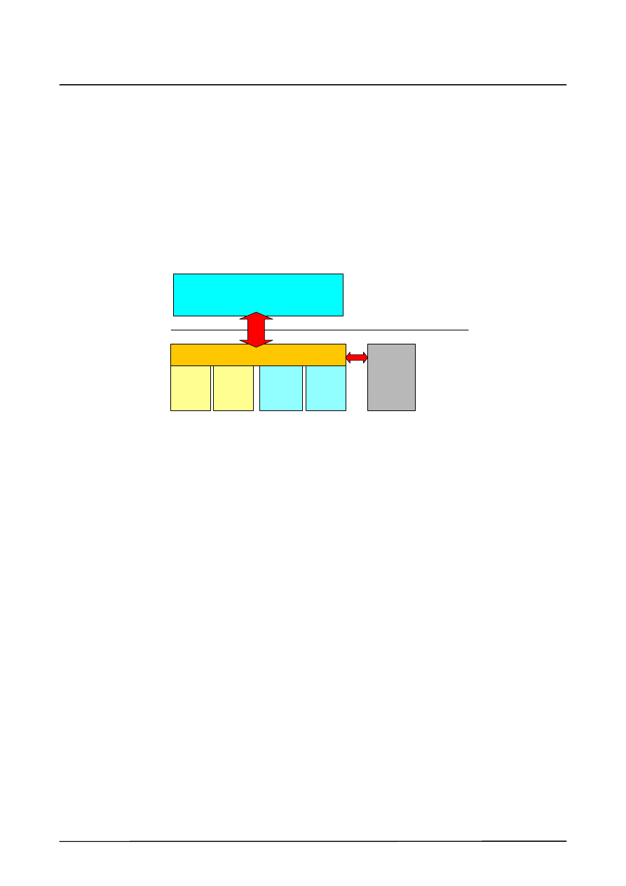
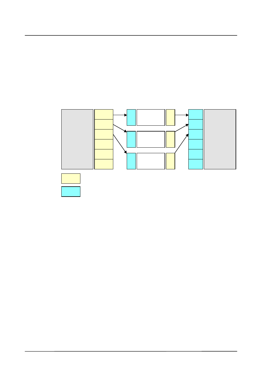
The following diagram shows the structure and integration of RSI schematically.
RSI
KRL
Position
control
Real--time
Not in
real--time
Sensor
driver
Sensor
driver
Object
Lib--
rary
Object
Lib--
rary
I/Os
2.2
Method of operation of RSI
The modularly--structured program RSI operates within the robot controller. RSI provides an
interface to KRL (KUKA Robot Language) by means of which the user, while working on the
KRL level, can access the functions made available by RSI.
Object--independent RSI commands make it possible to standardize the development of
various applications. RSI makes a number of additional internal function interfaces available
internally.
The application itself is implemented in KRL. New solutions and expansions can be
developed on the basis of existing components. The range of functions (commands,
supported sensors, etc.) is expandable in the form of libraries.
RSI is object--oriented. This means that no commands are processed as such; instead, RSI
commands are used to create objects and change their characteristics. Once the objects
have been created and activated, they are then evaluated continuously in parallel with a
running program.
RSI provides a set of commands for standard applications, for example functions for control-
ling velocity and position, transformations, comparison operations, etc.
The sensor data are evaluated in parallel with a running program, thus making it possible to
monitor the motion sequences. Programs can be created largely independently of the sensor
being used, and is based on the “object libraries” principle. Highly complex applications with
many different sensors can be implemented by working with a number of different libraries
simultaneously.
Robot Sensor Interface (RSI)
8 of 46
RSI_Rel. 2.0 10.02.01 en
2.3
RSI objects
2.3.1
Object components
2.3.1.1 Structure
An RSI object essentially consists of:
G
inputs,
G
outputs and a
G
function
Each individual object may contain only inputs, only outputs, or both inputs and outputs. In
each interpolation cycle (IPO cycle), the function evaluates the states or values present at
the inputs, and makes the results available at the corresponding outputs. It is also possible
to assign parameters which determine the characteristics of the object.
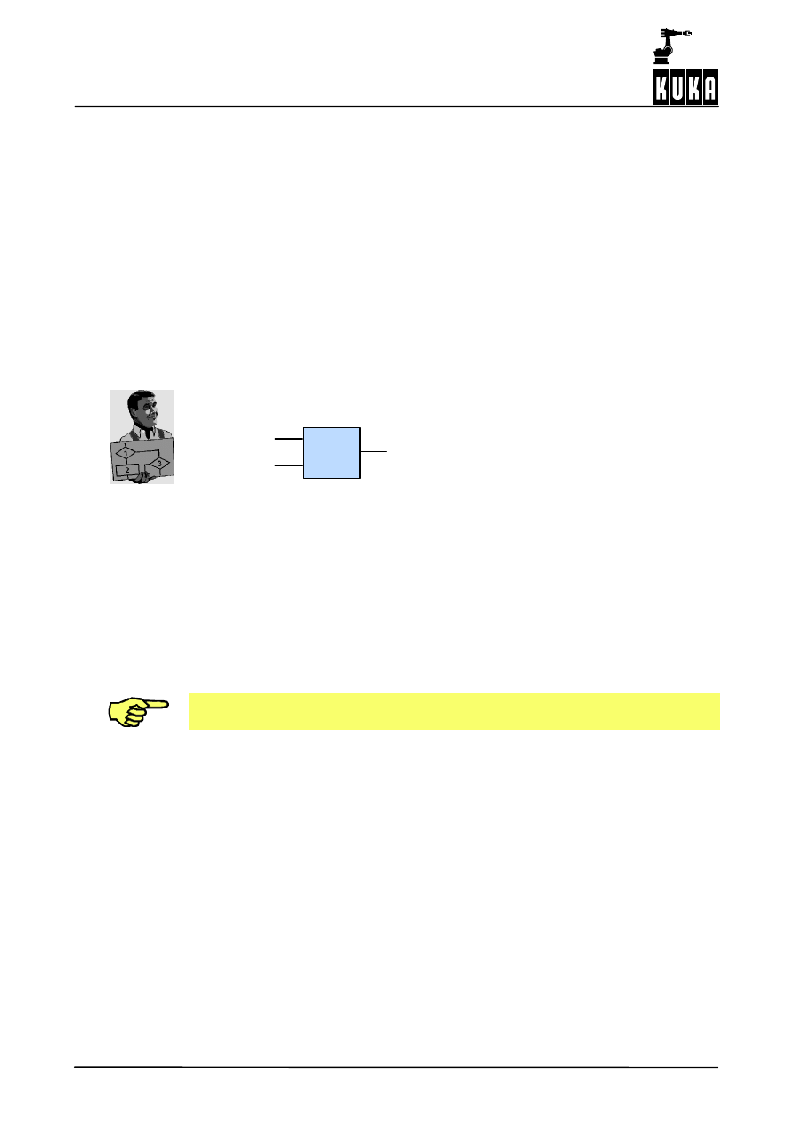
Example: Binary ANDing
&
Input
Input
Output
Function
This example comprises an object with two inputs and one output.
The AND function has the effect that the output is set to logic 1 if both inputs have been
assigned a logic 1. This function is executed in each interpolation cycle.
Object inputs can be either mandatory or optional. Mandatory inputs must be assigned, while
optional ones may or may not. The characteristics “Mandatory” and. “Optional” cannot be
altered subsequently.
Each input and output is assigned a unit, which must correspond to the characteristics of the
object. For example, an input which is linked to a force sensor and receives values in newtons
[N], must not be linked with an AND object, because AND objects expect to receive Boolean
values at their inputs.
The program checks that the units are correct; if an input is linked with an output whose
unit is incompatible, then an error will occur during the program’s run time.
Objects can be created, activated, checked, parameterized, deactivated and deleted.
Creation, linking, activating, deactivating and deleting of objects is carried out by means of
KRL commands. This allows creation of applications within KRL. The execution of created
and activated objects, on the other hand, takes place in parallel with the KRL program, thus
making monitoring and online path correction possible.
2
Program description (continued)
9 of 46
RSI_Rel. 2.0 10.02.01 en
2.3.1.2 RSI units
To make the use of RSI units easier and more user--friendly, a number of predefined units
are available in the program. These units are coded as constants in RSI.
RSI contains a set of predefined constants of commonly--used RSI base units:
;RSI SI Units:
RSIUNIT_No
=
0
;[--]
RSIUNIT_m
=
’H1’
;[m] meters
RSIUNIT_kg
=
’H10’
;[kg] kilograms
RSIUNIT_s
=
’H100’
;[s] seconds
RSIUNIT_A
=
’H1000’
;[A] amperes
RSIUNIT_K
=
’H10000’
;[K] Kelvin
RSIUNIT_cd
=
’H100000’
;[cd] candelas
RSIUNIT_mol
=
’H1000000’
;[mol] moles
;End RSI Units
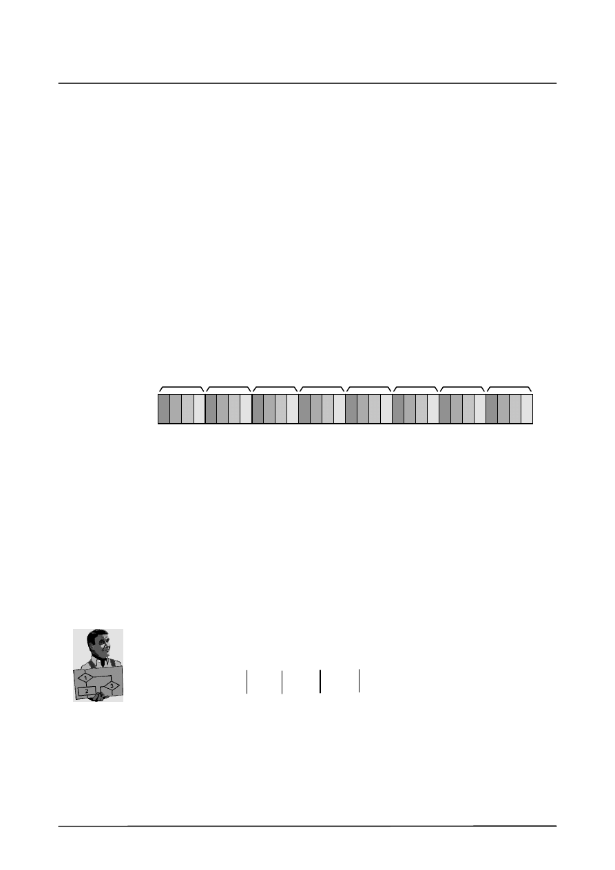
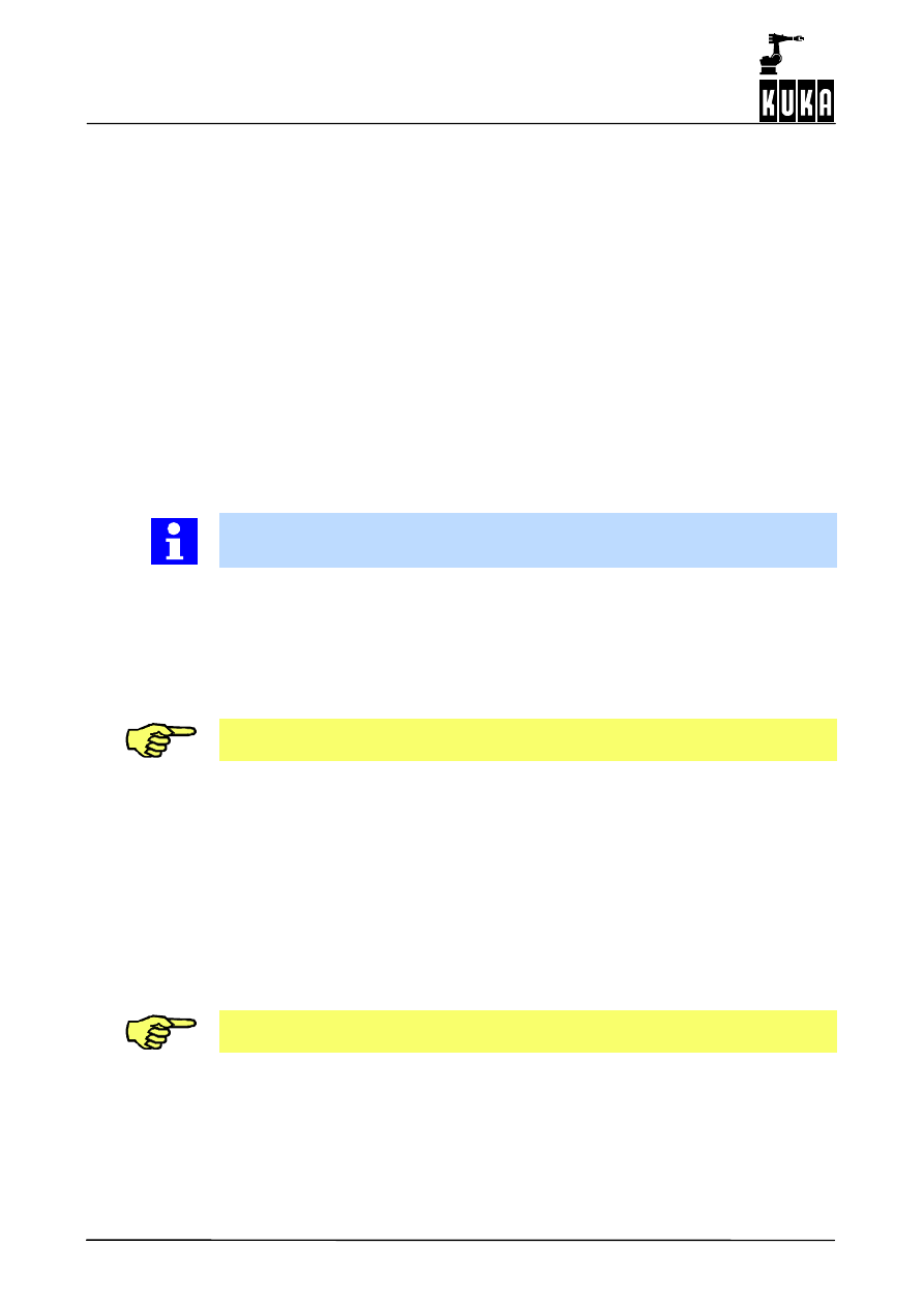
The units are coded by means of 32--bit variables. Four bits are available for each base unit.
These 4 bits specify the power of the unit; a 0 (zero) indicates that the unit is not present.
This is illustrated in the following diagram:
m
kg
s
A
K
cd
mol
not assigned
Meters
kilograms
seconds
amperes
Kelvin
candelas
moles
Material
quantity
Light
intensity
Temper-- Current
intensity
Time
Mass
Length
MSB
(Most Significant Bit)
LSB
(Least Significant Bit)
ature
The unit “meter” [m] thus corresponds to 1 or “H1”, and “kilogram” [kg] to 16 or “H10”.
Composite units are formed by combining other units. Of these, the following are
provided:
;RSI composite Units:
RSIUNIT_N
=
’HE11’
;[N] newtons
RSIUNIT_Nm
=
’HE12’
;[Nm] newton--meters
RSIUNIT_V
=
’HFE12’
;[V] volts
RSIUNIT_Pa
=
’HE1F’
;[Pa] pascals
;End RSI composite Units
N = kgm/s
2
= ’H10’ + ’H1’ + ’HE00’ = ’HE11’
kg + m
+ s
2
= N
For example, the composite unit “newton” [N] is as follows:
In this manner it is possible to code any unit up to a power of +/-- 8.
Robot Sensor Interface (RSI)
10 of 46
RSI_Rel. 2.0 10.02.01 en
2.3.2
Creating objects
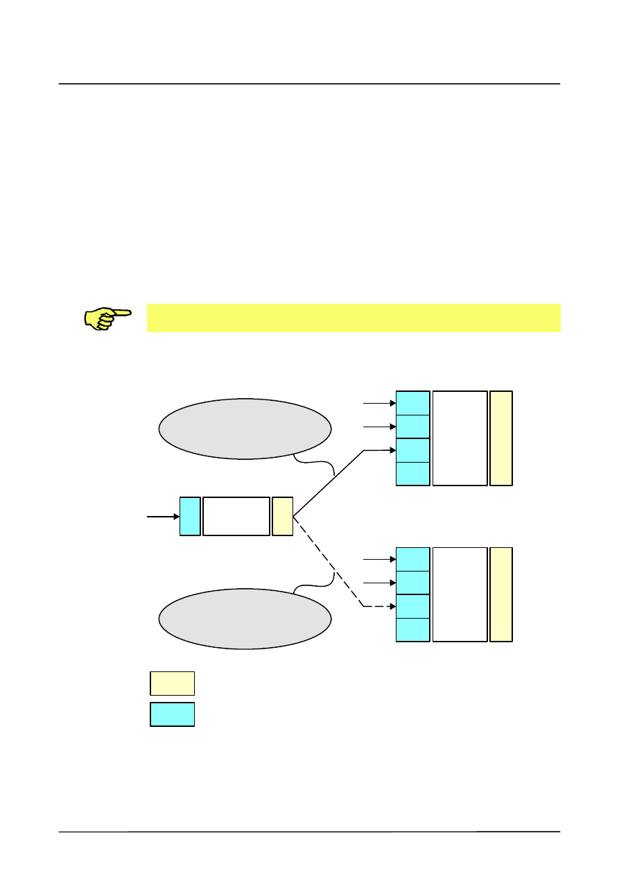
Each object is created according to the specific case, but the structure of the commands is
basically identical. The command to create an object looks essentially like this:
Return value
=
Object name(Handle, ContainerID,
[{ObjHandle, Output}], [{Parameter}])
The following definitions apply here:
Return value
The return value indicates whether the object was created
successfully.
If the object was created successfully, then ENUM RSI_OK
is returned; otherwise another one corresponding to
the error will be returned.
Object name
Name of the object to be created, for example “ST_AND”
Handle
A variable which is written when the object is created.
The handle is used for subsequent access to the object.
ContainerID
Number of the container in which the object is created.
ObjHandle
A handle defining the object with which the created object
is linked.
The link is made via the output of the object defined by the parameter
Output.
Output
Specifies the output of the object selected using ObjHandle.
The parameters ObjHandle and Output can be used repeatedly
if more than one link is present.
Parameter
Additional parameters required for the object’s function, for
example the gain factor of a P controller.
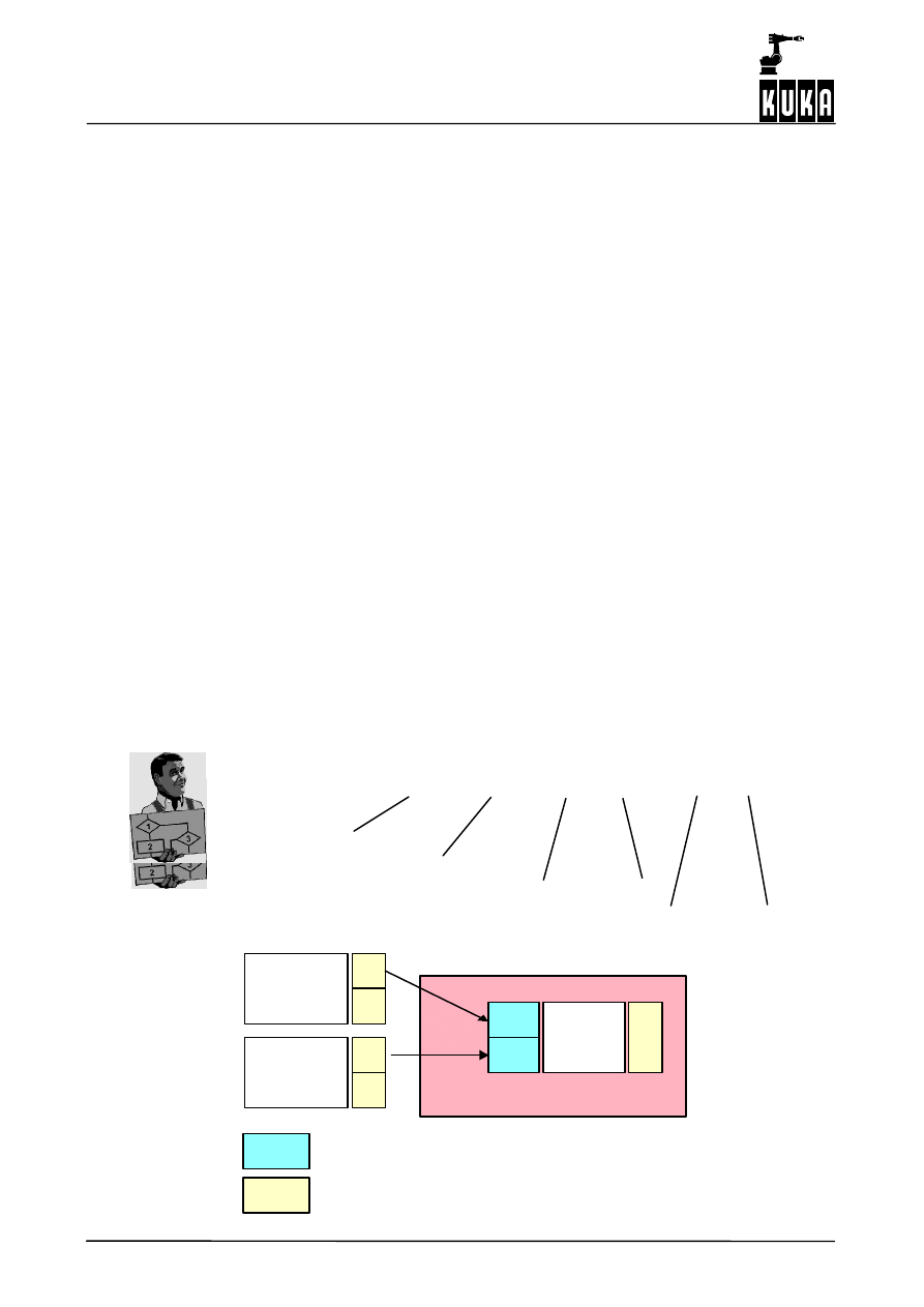
Example: ST_AND
An AND object is created in container 2 and linked with the objects GREATID1, output 1 and
GREATID2, output 1.
Example
AND object
err=ST_AND(ANDID, 2, GREATID1, 1, GREATID2, 1)
An AND object
is created in container 2,
and linked with the objects GREATID1, output 1
and GREATID2, output 1
1
1
1
1
...
...
2
AND
GREATID1
GREATID2
X
X
Output “X” indicates the number of the output.
Input “X” indicates the number of the input.
Container 2
2
Program description (continued)
11 of 46
RSI_Rel. 2.0 10.02.01 en
2.3.3
Linking objects
Objects can be linked to one another – by linking outputs with inputs. The mandatory links
are part of the KRL command for creating the objects.
To create optional links, the command “ST_NEWLINK” is available. The command
“ST_DELLINK” is used to delete these links. In addition, the command “ST_CHANGELINK”
can be used to redirect a link.
In all three commands, a link is defined from the output of one object to the input of another
object. In order to create, change, or delete a link, the following conditions must be met:
G
the object IDs of the objects must be valid; the objects must actually exist;
G
the corresponding inputs and outputs must be present;
G
the units must be the same;
G
the number of links to other objects must not exceed 24 per object.
Each of these conditions is checked by the program. If one of these conditions is not
fulfilled, the robot is stopped and the corresponding error message is generated.
The following diagram shows in schematic form the functions of “ST_NEWLINK”,
“ST_DELLINK” and “ST_CHANGELINK”.
1
1
1
1
2
2
3
3
...
...
OR
(orid)
AND
(andid)
NOT
(notid)
1
1
X
X
Output “X” indicates the number of the output.
Input “X” indicates the number of the input.
Link
-- create with ST_NEWLINK
-- delete with ST_DELLINK
Link
-- change with ST_CHANGELINK
Syntax of the command “ST_NEWLINK”
err=st_newlink(notid, 1, andid, 3)
In this example a link is created from the NOT object “NOTID”, output 1 to the AND object,
input 3.
Robot Sensor Interface (RSI)
12 of 46
RSI_Rel. 2.0 10.02.01 en
Syntax of the command “ST_DELLINK”
err=st_dellink(notid, 1, andid, 3)
The link from the NOT object “NOTID”, output 1 to the AND object, input 3 is deleted.
Syntax of the command “ST_CHANGELINK”
err=st_changelink(notid, 1, andid, 3, orid, 3)
The link between the NOT object “NOTID”, output 1 and the AND object, input 3 is cancelled
and instead a link is created to the OR object “ORID”, input 3.
2.3.4
Containers
A container does not provide any function of its own, but is rather used for logical
management of objects. The objects in a single container can be activated, deactivated and
deleted together.
The total number of RSI objects is 100.
The KRL commands for a container are the same as the corresponding commands for
objects:
ST_ENABLE
activates the group of objects present in the container;
ST_DISABLE
deactivates the group of objects present in the container;
ST_DELOBJ
deletes the container and the group of objects present in it.
Using these commands always affects both the container and all of the objects it
contains.
The container makes it possible to edit a group of objects simultaneously. This makes it easy
to switch on and off functions consisting of a group of interlinked objects.
If a container is deactivated or deleted, and an object in the container is linked with another
object outside that container, and if the link is mandatory, then an error will occur during the
program’s run time.
When the system is started a container with the ID 0 (zero) is created automatically.
Container 0 is always activated, and the objects it contains are evaluated.
Further containers (1, 2, etc.) are created during run time by means of the command
“ST_CONTAINER”. These containers (and thus their contents) are initially always
deactivated, and are activated by means of the command “ST_ENABLE”. The objects
always acquire the status of the container.
Deactivation or deletion of an object causes an error during program run time if the
outputs of the object in question are linked with the inputs of another object.

2
Program description (continued)
13 of 46
RSI_Rel. 2.0 10.02.01 en
2.3.5
Changing object parameters
Object parameters are required for an object’s function. They can be – but do not have to
be – identical to the parameters set when the object is created.
During run time of an object, object parameters can be read using the command
“ST_GETPARAM”, and written using the command “ST_SETPARAM”. These two
commands can be used for any object which contains object parameters.
Example
The gain factor of a proportional--action object (P object) will be changed from 0.01745 to
a value of 0.5.
The P controller is created as follows:
err=st_p(propid,1, posid, 2, 0.01745, 0)
(P object “ST_P”)
(gain factor)
In the above example the designation “PROPID” is the handle of the P object, and the
“1” specifies that the first parameter will be altered.
If there is more than one parameter they are numbered sequentially from 1 to n.
Once the P controller has been created, the gain factor (0.01745) can be changed to the
value 0.5 by means of the command
err=ST_Setparam(propid,1,0.5) 0)
Robot Sensor Interface (RSI)
14 of 46
RSI_Rel. 2.0 10.02.01 en
2.3.6
Debugging
2.3.6.1 Log file
RSI keeps a log file as an aid in troubleshooting. This file is named “RSIALL.LOG”, and is
located in the directory “...\KRC\ROBOTER\LOG”.
The log file contains extensive information, for example regarding when the individual objects
were created and what other objects they have been linked to. In addition, all errors which
occur are saved in this file, for example incompatible units when linking objects.
2.3.6.2 Error messages
RSI run time errors caused by incorrect programming are indicated by the error message
“Error when Function X was running”.
Here “X” stands for the corresponding error code. The following table provides a list of the
numeric codes and their meanings. For example, code “11” signifies that an error has oc-
curred in the function “ST_Container”.
For detailed information on errors which may have occurred, please refer to the log file
“RSIALL.LOG”, which is located in the directory “...\KRC\ROBOTER\LOG”.
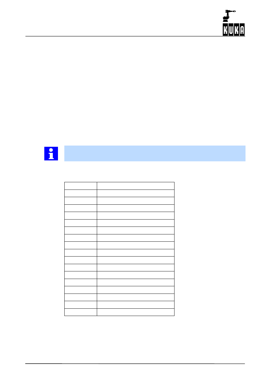
Table of error messages
Code
Error in object/function
2
INT _ST_RESET
3
INT _ST_DELOBJ
4
INT _ST_GETPARAM
5
INT _ST_TESTOBJ
6
INT _ST_TESTMODULE
7
INT _ST_SETPARAM
8
INT _ST_NEWLINK
9
INT _ST_DELLINK
10
INT _ST_CHANGELINK
11
INT _ST_CONTAINER
12
INT _ST_DISABLE
13
INT _ST_ENABLE
16
INT _ST_SN2TTS
17
INT _ST_SN2BASE
18
INT _ST_SN2WORLD
19
INT _ST_AND
20
INT _ST_OR

2
Program description (continued)
15 of 46
RSI_Rel. 2.0 10.02.01 en
Code
Error in object/function
21
INT _ST_XOR
22
INT _ST_NOT
23
INT _ST_EQUAL
24
INT _ST_LESS
25
INT _ST_GREATER
32
INT _ST_VEL
33
INT _ST_POS
34
INT _ST_P
35
INT _ST_PD
36
INT _ST_I
37
INT _ST_PID
38
INT _ST_SUM
39
INT _ST_AVERAGE
40
INT _ST_FIR
41
INT _ST_STOP
42
INT _ST_MAP2VAR
43
INT _ST_SETOUT
44
INT _ST_RESETOUT
45
INT _ST_MAP2OUT
47
INT _ST_SN2TOOL
48
INT _ST_ACTPOS
49
INT _ST_PATHCORR
50
INT _ST_DIGIN
51
INT _ST_ANAIN
52
INT _ST_GENTRANS
53
INT _ST_ACTAXIS
54
INT _ST_AXIS_CORR
55
INT _ST_PT1
56
INT _ST_PT2
Robot Sensor Interface (RSI)
16 of 46
RSI_Rel. 2.0 10.02.01 en
2.4
Structure of a sensor application
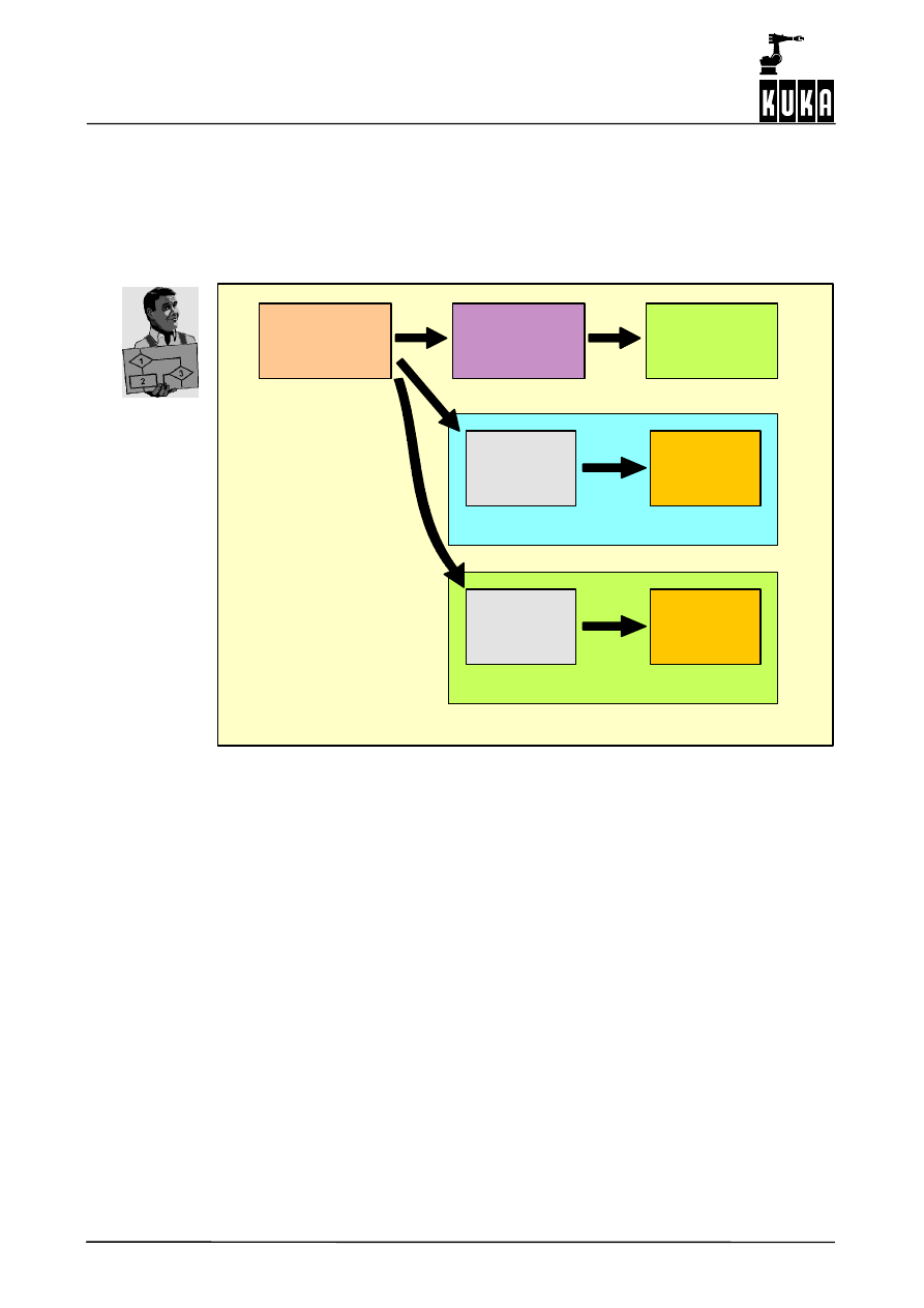
An application is defined by the data flow between its objects. Each object provides a specific
function. Within each function, the data at the object’s inputs are read, processed in the
object itself, and the results are made available at the object’s outputs.
Functions can be combined in almost any manner desired by linking the corresponding
inputs and outputs. The following diagram provides an illustration of functions and data flow.
Sensor
Transformation
Path correction
Comparison 1
Comparison 2
Stop
Stop
Container 1
Container 2
Container 0
This example shows an application which uses sensors to monitor the motion of the robot
and makes the appropriate path corrections. Monitoring of the sensor data takes place at the
same time. The function of the object executing path correction controls the position of the
robot by evaluating the sensor data present at the object’s inputs.
In the example shown, the data received from the sensor are transformed by a
transformation object and passed on to the path correction object. Since the data flow
between the three objects is evaluated parallel to the running KRL program in each
interpolation cycle, the data received from the sensor can be used to correct the path
immediately.
Applications can be structured more clearly through the creation of “Containers”. Containers
have no functions of their own, but serve rather to bring objects together into groups. In
addition, containers can be used to activate or deactivate groups of objects.
Two containers are defined in our example (containers 1 and 2), each of which contains one
comparison object (Comparison 1 and Comparison 2) and one stop object. These can be
used to check the size of the value received from the sensor, for example. If the value
received from the sensor exceeds a specified value, then the robot is stopped.
If within a single application a number of comparisons using different monitoring values are
required, for example depending on the position of the robot or other specific circumstances,
containers can be created to allow simple switching between the threshold values which
must be used in each case. This is done by activating or deactivating the appropriate
containers.
This method can be used to group all the objects required for path correction, as well as any
additional containers, in a single container (Container 0 in the example shown); it is thus
possible to switch the path correction function on or off at any time.

2
Program description (continued)
17 of 46
RSI_Rel. 2.0 10.02.01 en
Creation, linking, activating, deactivating and deleting of objects is carried out by means of
KRL commands. This allows creation of applications within KRL. The execution of created
and activated objects, on the other hand, takes place in parallel with the KRL program, thus
making monitoring and online path correction possible.
Robot Sensor Interface (RSI)
18 of 46
RSI_Rel. 2.0 10.02.01 en
2.5
Program example
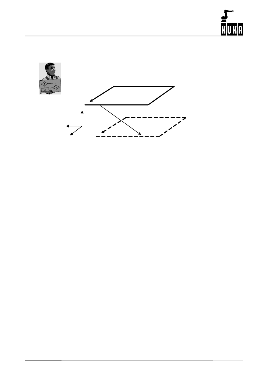
Traversing the robot with the aid of a force--moment sensor
The robot moves along a programmed path which will be corrected by means of a force--
moment sensor. The data from the force--moment sensor are evaluated and the calculated
correction values trigger the appropriate path correction. The correction values are
superposed on the programmed values.
Originally programmed
Path after sensor correction
Z
Y
X
1
2
path
A force acts on the sensor between 1 and 2. This force triggers the appropriate path
correction, thus shifting the path. This shift remains even after the force ceases to act on the
sensor, i.e. after the correction, because the sensor values have been integrated.
The program for this example is structured as follows:
;------ Variable declarations ------
decl RSIERR err
int dlrid, pid[3], skalid[6], skalkrft
...
;------ Programming of the sensor task ------
;------ Define sensor ------
err=ST_DLRSENS(dlrid,0)
;------ Define object for Cartesian position correction ------
err=ST_PATHCORR (skalkrft,0)
;------ Define integrators to allow large distances to be covered
;------ One integrator with one force value is linked each direction (X, Y and Z)
;------ of the sensor
err=ST_I (skalid[1],0,dlrid,1,0.0001,0)
err=ST_I (skalid[2],0,dlrid,2,0.0001,0)
err=ST_I (skalid[3],0,dlrid,3,0.0001,0)
;------ Adjust units over P adapter
err=ST_P (pid[1],0,skalid[1],1,1,1)
err=ST_P (pid[2],0,skalid[2],1,1,1)
err=ST_P (pid[3],0,skalid[3],1,1,1)
;------ Link the position correction object with the P adapters
err=ST_NEWLINK (pid[1],1,skalkrft,1)
err=ST_NEWLINK (pid[2],1,skalkrft,2)
err=ST_NEWLINK (pid[3],1,skalkrft,3)
; Switch on the RSI
err=ST_ON()
2
Program description (continued)
19 of 46
RSI_Rel. 2.0 10.02.01 en
;------ Robot motion program ------
...
;------ The corrections made by the sensor are superposed on the motions
LOOP
LIN_REL
{x 100}
LIN_REL
{y 100}
LIN_REL {x -100}
LIN_REL {y -100}
ENDLOOP
...
Graphic representation of objects created
1(Fx)
1 X
2(Fy)
2 Y
3(Fz)
3 Z
4(Mx)
4 A
5(My)
5 B
6(Mz)
6 C
Force--
moment
sensor
(DLRID)
Position
correction
(SKALKRFT)
I controller
SKALID[1]
I controller
SKALID[2]
I controller
SKALID[3]
1
1
1
1
1
1
X
X
Output “X” indicates the number of the output.
Input “X” indicates the number of the input.
Description of the program
ST_DLRSENS(dlrid,0)
G
“St_DLRSENS” creates a sensor object which is used to access the force--motion
sensor.
G
The handle “dlrid” is a variable defined by RSI. This makes it possible to access the
object later in the program.
G
“0” (zero) signifies that the sensor object is created in Container 0 (zero).
ST_PATHCORR (skalkrft,0)
G
“ST_PATHCORR” is an object used for Cartesian correction of the robot position.
Position correction allows path correction while robot motions are being executed.
G
The handle “skalkrft” allows subsequent access to the position correction object.
G
“0” (zero) signifies that the correction object is created in Container 0 (zero).
Robot Sensor Interface (RSI)
20 of 46
RSI_Rel. 2.0 10.02.01 en
ST_I (skalid[1...3],0,dlrid,1...3,0.0001,0)
G
“ST_I” is an integrator. Three integrators are defined for the purpose of integrating the
force values in X, Y and Z.
G
The handles of these integrators are saved in the variables “skalid[1...3]”.
G
The integrators are created in Container 0.
G
The handle “dlrid” with the output number (1...3) creates the link between the sensor
object and the integrator. This link gives the integrator access to the corresponding
force values.
G
The value “0.0001” in this example is the gain factor for the integrator.
G
The final “0” (zero) signifies that the force values are superposed continuously (for more
information on this topic, please refer to the description of RSI command “ST_I” in
Section 3.5.2.4 of this documentation).
ST_NEWLINK (skalid[1...3],1,skalkrft,1...3)
“ST_NEWLINK” is used to create a link from an integrator (1...3) to an input of the position
correction object.
In this example, the handles “skalid[1],1,skalkrft,1” have the following meaning:
A link is created from output 1 of the object “skalid[1]” to input 1 of the object “skalkrft”.
The position correction object can thus access the superposed force values and make the
corresponding corrections to the robot position.
At this point the RSI objects have been created and linked to each other, but they are still
not active, and therefore have no effect within the robot controller.
Activation is carried out using the command:
ST_ON()
The command “ST_ON” initiates RSI program execution. From this point onwards the RSI
objects are evaluated in each interpolation cycle.
3
RSI commands
21 of 46
RSI_Rel. 2.0 10.02.01 en
3
RSI commands
This section contains a description of the RSI commands supplied with
the program on delivery (standard version).
3.1
Structure of command descriptions
The tables on the following pages are structured as follows:
ST_...
Name of the RSI command. RSI commands always begin with “ST_”.
Description
Name of the RSI command, its function and any instructions which must
be observed.
Parameters
Parameters are used to create RSI objects.
Example:
IN (INT): ID1
Object ID of the object which is linked with the
input.
IN (INT): CHANNEL1
Index of OBJ1
ID1 and CHANNEL1 indicate the output of the object
which is linked with the input.
Object inputs
Inputs of the object during run time.
Example:
1 (INT):
Value
Object outputs
Outputs of the object which are available during run time. These outputs are
available for use by other objects.
Example:
1 (REAL):
X position in Base [mm]
Object
parameters
Parameters which can be altered during program run time. These are used with
the commands “ST_SETPARAM” and “ST_GETPARAM”.
Object Enums
Expansion of the individual parameters.
Return value
Value returned when the object is created.
Example:
RSIOK:
Successful
The RSI object was saved successfully.
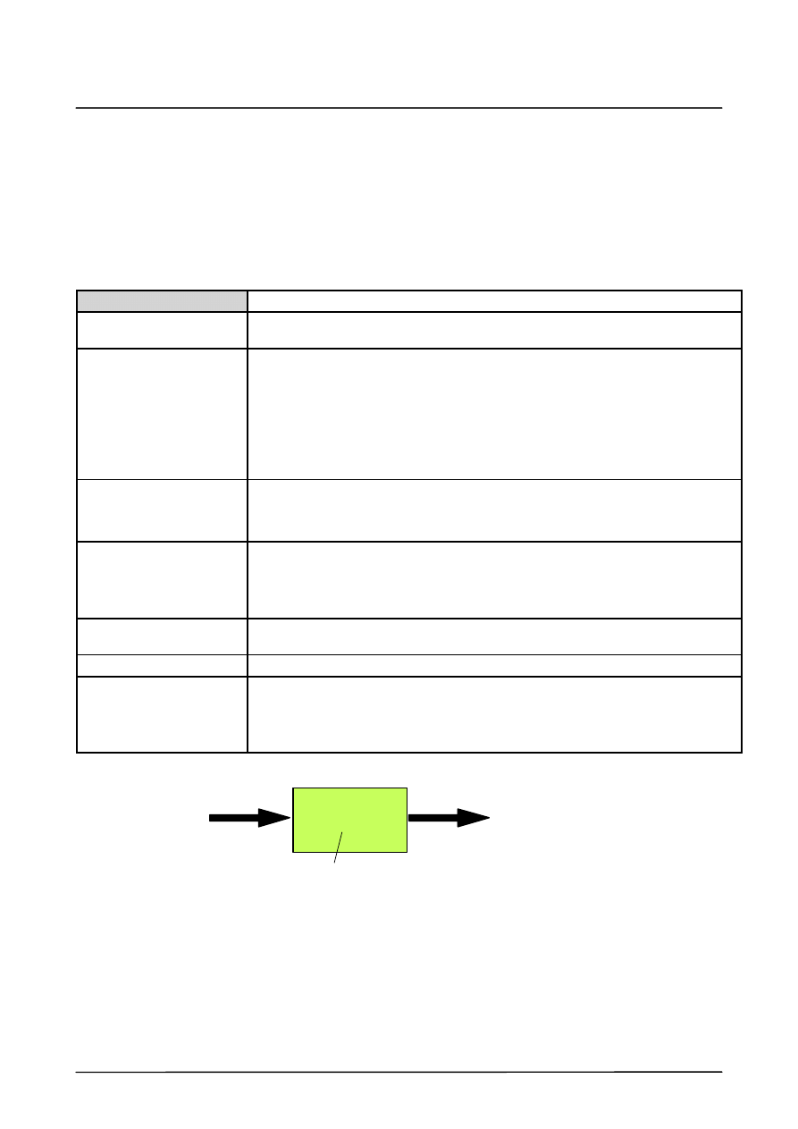
P
Object parameters
Object input
Object output
Example: The command “ST_P”
The corresponding command is as follows:
ST_P (object ID[handle], container ID, input object ID, index of the input object ID, control
parameters, unit)
Robot Sensor Interface (RSI)
22 of 46
RSI_Rel. 2.0 10.02.01 en
3.2
General commands
General RSI commands are described in this section. Further information on this topic can
be found in Section 2.
ST_ON
Description
Initiates RSI program execution. Once RSI has been started, all RSI objects are
executed in the specified sequence in each sensor cycle.
Parameters
None
Return value
RSIOK:
Successful
ST_OFF
Description
Terminates RSI program execution.
Parameters
None
Return value
RSIOK:
Successful
ST_RESET
Description
Deletes all RSI objects.
Parameters
None
Return value
RSIOK:
Successful
ST_TESTMODULE
Description
Checks whether the module specified by “MODULENAME” has been loaded.
Parameters
IN (CHAR[]): MODULENAME File name of the module
Return value
TRUE:
Module loaded.
FALSE:
Module not loaded.
ST_TESTRSI
Description
Checks whether the RSI basic module has been loaded. If this is not the case,
the corresponding message will be displayed.
Parameters
IN (BOOL): QUITMSG Flag for message display.
TRUE: Message is displayed;
FALSE: Message is not displayed;
Return value
TRUE:
RSI module loaded.
FALSE:
RSI module not loaded.

3
RSI commands (continued)
23 of 46
RSI_Rel. 2.0 10.02.01 en
ST_SETPARAM
Description
Sets the parameter of an object. The parameter is specified by the parameter ID.
Parameters
IN (INT): OBJID
Object ID
IN (INT): PARAMID
Parameter ID
IN (REAL): PARAM
Value to be set.
Return value
RSIOK:
Successful
RSIINVOBJID:
Invalid object ID.
RSIINVPARAMID:
Invalid parameter ID.
RSIINVPARAM:
Invalid parameter setting.
ST_GETPARAM
Description
Polls a parameter of an object.
Parameters
OUT (REAL): PARAM Supplies the parameter polled.
IN (INT): OBJID
Object ID of the poll.
IN (INT): PARAMID
Parameter ID of the poll.
Return value
RSIOK:
Successful
RSIINVOBJID:
Invalid object ID.
RSIINPARAMID:
Invalid parameter ID.
ST_TESTOBJ
Description
Checks whether an object with the corresponding ID is present.
Parameters
OUT (BOOL): EXIST
Flag of the existing object.
IN (INT): OBJID
Object ID of the query.
Return value
RSIOK:
Successful
RSIINVOBJID:
Invalid object ID.
ST_ENABLE
Description
Activates an RSI object.
Activated RSI objects are executed after “ST_ON” is called in KRL.
Parameters
IN (INT): OBJID Object ID of the RSI object to be activated.
Return value
RSIOK:
Successful
ST_DISABLE
Description
Deactivates an RSI object.
Deactivated RSI objects are not executed in the sensor cycle.
Deactivation is only permissible if the object has no active following object.
Parameters
IN (INT): OBJID Object ID of the RSI object to be deactivated.
Return value
RSIOK:
Successful
RSIINVOBJID: Invalid object ID.

Robot Sensor Interface (RSI)
24 of 46
RSI_Rel. 2.0 10.02.01 en
ST_DELOBJ
Description
Deletes an RSI object.
An RSI object may only be deleted if it has no active following object.
Parameters
IN (INT): OBJID Object ID of the RSI object to be deleted.
Return value
RSIOK:
Successful
RSIINVOBJID: Invalid object ID.
RSIHASSUCC: Deletion prevented by following object.

3
RSI commands (continued)
25 of 46
RSI_Rel. 2.0 10.02.01 en
3.3
Link commands
Link commands are used to link objects. Links can be created (ST_NEWLINK), deleted
(ST_DELLINK) and changed (ST_CHANGELINK). Further information on this topic can be
found in Section 2.3.3.
ST_NEWLINK
Description
Links the output of an RSI object with the input of a different RSI object and
updates the instructions.
Parameters
IN (INT): OBJFROM
Object ID of the output RSI object.
IN (INT): CHFROM
Index of the output.
IN (INT): OBJTO
Object ID of the input RSI object.
IN (INT): CHTO
Index of the input.
Return value
RSIOK:
Successful
RSILNKOUTOBJ: Invalid output object.
RSILNKINOBJ:
Invalid input object.
RSILNKOUTID:
Invalid output object ID.
RSILNKINID:
Invalid input object ID.
RSILNKSIGNAL:
Input and output signals incompatible.
ST_DELLINK
Description
Deletes the link between the output of an RSI object and the input of a different
RSI object and updates the instructions.
Parameters
IN (INT): OBJFROM
Object ID of the output RSI object.
IN (INT): CHFROM
Index of the output.
IN (INT): OBJTO
Object ID of the input RSI object.
IN (INT): CHTO
Index of the input.
Return value
RSIOK:
Successful
RSIBAD:
Internal error.
RSIINVINPID:
Invalid input object ID.
RSIINVOUTID:
Invalid output object ID.
RSIINVINPIND:
Invalid input object index.
RSIINVOUTIND:
Invalid output object index.
RSIINVLNK:
Invalid link.
ST_CHANGELINK
Description
Changes the output connection of an existing link and updates the instructions.
Parameters
IN (INT): OUTOBJID
Object ID of the output object of the link to be changed.
IN (INT): OUTCHID
Index of the output to be changed.
IN (INT): INOBJID
Object ID of the link input (unchanged).
IN (INT): INCHID
Index of the input (unchanged).
IN (INT): NEWOUTOBJID New object ID of the output.
IN (INT): NEWOUTCHID New index of the output.
Return value
RSIOK:
Successful
Robot Sensor Interface (RSI)
26 of 46
RSI_Rel. 2.0 10.02.01 en
3.4
Motion commands
All of the motion commands described below are used to initiate motions which can be can-
celled while the motion is being executed.
Such a cancellation is not, however, part of the motion command in question, but must rather
be programmed separately by setting a special output using the variable “RSI_BREAK”,
which is defined in the file “$CONFIG.DAT”.
Never enter the number of the output here; instead always use the variable
“RSI_BREAK”. This way you can simply change the number of the output being used,
without having to change the program.
In place of the predefined output, you can also use a different variable. To do this, make
the appropriate changes to the signal “RSIBREAK” in the file “RSILIB.DAT” (in directory
“...\KRC\ROBOTER\KRC\R1\TP\RSI”).
;Break a motion with signal
;
SIGNAL RSIBREAK $OUT[8]
Example
Cancellation of a LIN motion.
err=ST_DLRSENS(dlrid,0)
err=ST_LESS (compid[1],0,dlrid,3,0,0,-10,1)
err=ST_GREATER (compid[2],0,dlrid,3,0,0,10,1)
err=ST_OR (orid,0,compid[1],1,compid[2],1)
err=ST_SETDIGOUT (outid,0,orid,1,RSI_BREAK)
err=ST_ON()
;--- LIN motion which is to be cancelled ---
ST_SKIPLIN (P1)
ST_SKIPPTP
Description
Executes a PTP motion to a specified point. This PTP motion can be cancelled
by means of a BREAK signal. In this case, a subsequent motion command will
cause the path to continue towards the destination point of that command.
No reverse motion is executed to the start point of the PTP motion which was
cancelled by the BREAK signal.
Parameters
IN (E6POS): E6P Destination point of the PTP motion.
Return value
None
ST_RETPTP
Description
Executes a PTP motion to a specified point. This PTP motion can be cancelled
by means of a BREAK signal. In this case, reverse motion is executed to the
start point of the PTP motion.
Parameters
IN (E6POS): E6P Destination point of the PTP motion.
Return value
None
3
RSI commands (continued)
27 of 46
RSI_Rel. 2.0 10.02.01 en
ST_SKIPLIN
Description
Executes a LIN motion to a specified point. This LIN motion can be cancelled by
means of a BREAK signal. In this case, a subsequent motion command will
cause the path to continue.
No reverse motion is executed to the start point of the LIN motion which was
cancelled by the BREAK signal.
Parameters
IN (E6POS): E6P Destination point of the LIN motion.
Return value
None
ST_RETLIN
Description
Executes a LIN motion to a specified point. This LIN motion can be cancelled by
means of a BREAK signal. In this case, reverse motion is executed to the start
point of the LIN motion.
Parameters
IN (E6POS): E6P Destination point of the LIN motion.
Return value
None
ST_SKIPCIRC
Description
Executes a CIRC motion to a specified point. This CIRC motion can be cancelled
by means of a BREAK signal. In this case, a subsequent motion command will
cause the path to continue.
No reverse motion is executed to the start point of the CIRC motion which was
cancelled by the BREAK signal.
Parameters
IN (E6POS): E6P Intermediate point of the CIRC motion.
IN (E6POS): E6P Destination point of the CIRC motion.
Return value
None
ST_RETCIRC
Description
Executes a CIRC motion to a specified point. This CIRC motion can be cancelled
by means of a BREAK signal. In this case, reverse motion is executed to the
start point of the CIRC motion.
Parameters
IN (E6POS): E6P Intermediate point of the CIRC motion.
IN (E6POS): E6P Destination point of the CIRC motion.
Return value
None

Robot Sensor Interface (RSI)
28 of 46
RSI_Rel. 2.0 10.02.01 en
3.5
RSI objects
3.5.1
Data objects
ST_DIGIN
Description
Creates an RSI object which accesses digital inputs.
Parameters
OUT (INT): OBJID
Object ID of the RSI object being created.
IN (INT): AFID
Object ID of the container in which the RSI object
being created is located.
IN (INT): INDEX
See object parameter index.
IN (INT): LENGTH
Quantity of bits to be read (0: bit, 1: byte, 2: word)
IN (INT): UNIT
Unit of the input (no unit is required for
bit input).
Object outputs
1 (INT):
Digital input at the selected index.
Object
parameters
0 (INT): Index Value in length units of a digital input
(1--1026 for bit, 1--204 for byte, 1--40 for word).
Return value
RSIOK:
Successful;
RSIINVCONT: Invalid container;
RSIINVPARAM:Invalid object parameter index.
ST_ANAIN
Description
Creates an RSI object which accesses analog inputs.
Parameters
OUT (INT): OBJID
Object ID of the RSI object being created.
IN (INT): AFID
Object ID of the container in which the RSI object
being created is located.
IN (INT): INDEX
See object parameter index.
Object outputs
1 (REAL):
Analog input at the selected index.
Object
parameters
0 (INT): Index Index of the analog input (1--8)
Return value
RSIOK:
Successful;
RSIINVCONT: Invalid container;
RSIINVPARAM:Invalid object parameter index.
The appropriate drivers for the analog inputs must be installed. Otherwise this
command will cause an error during run time.

3
RSI commands (continued)
29 of 46
RSI_Rel. 2.0 10.02.01 en
ST_ACTPOS
Description
Creates an RSI object which supplies the current position of the robot
in the Cartesian coordinate system.
Parameters
OUT (INT): OBJID
Object ID of the RSI object being created.
IN (INT): AFID
Object ID of the container in which the RSI object
being created is located.
IN (INT): COSYS
Current position in the Base coordinate system.
Object outputs
1 (REAL): X Position of coordinate axis X [mm]
2 (REAL): Y Position of coordinate axis Y [mm]
3 (REAL): Z Position of coordinate axis Z [mm]
4 (REAL): A Rotation about the Z axis [rad]
5 (REAL): B Rotation about the Y axis [rad]
6 (REAL): C Rotation about the X axis [rad]
Return value
RSIOK:
Successful;
RSIINVCONT: Invalid container.
ST_ACTAXIS
Description
Creates an RSI object which delivers the current position of the robot
in the axis--specific coordinate system.
Parameters
OUT (INT): OBJID
Object ID of the RSI object being created.
IN (INT): AFID
Object ID of the container in which the RSI object
being created is located.
Object outputs
1 (REAL): A1 Rotation about axis 1 [rad]
2 (REAL): A2 Rotation about axis 2 [rad]
3 (REAL): A3 Rotation about axis 3 [rad]
4 (REAL): A4 Rotation about axis 4 [rad]
5 (REAL): A5 Rotation about axis 5 [rad]
6 (REAL): A6 Rotation about axis 6 [rad]
Return value
RSIOK:
Successful;
RSIINVCONT: Invalid container.

Robot Sensor Interface (RSI)
30 of 46
RSI_Rel. 2.0 10.02.01 en
ST_MAP2SEN_PINT
Description
Creates an RSI object which maps its input onto the variable “$SEN_PINT[...]”.
Parameters
OUT (INT): OBJID Object ID of the RSI object being created.
IN (INT): AFID
Object ID of the container in which the RSI object
being created is located.
IN (INT): ID1
Object ID of the object which is linked with the input.
IN (INT): CHANNEL1 Index of OBJ1 which is linked with the input.
IN (INT): VARID
Index (see object parameters).
Object inputs
1 (BOOL): Input condition
Object
parameters
0 (INT): Index Index of the variable “$SEN_PINT”
(valid range: 1 ... 20).
Return value
RSIOK:
Successful
RSIINVCONT:
Invalid container.
RSICONTOVERFLOW: Container overflow.
RSILNKOUTOBJ: Invalid output object ID (see log file).
RSILNKOUTINDEX: Invalid index in output object (see log file).
RSILNKSIGNAL:
Input and output signals incompatible
(see log file).
RSILNKPARAM:
Invalid object parameter.
ST_MAP2SEN_PREA
Description
Creates an RSI object which maps its input onto the variable “$SEN_PREA[...]”.
Parameters
OUT (INT): OBJID Object ID of the RSI object being created.
IN (INT): AFID
Object ID of the container in which the RSI object
being created is located.
IN (INT): ID1
Object ID of the object which is linked with the input.
IN (INT): CHANNEL1 Index of OBJ1 which is linked with the input.
IN (INT): VARID
Index (see object parameters).
Object inputs
1 (REAL): Value to be mapped
Object
parameters
0 (INT): Index Index of the variable “$SEN_PREA”
(valid range: 1 ... 20).
Return value
RSIOK:
Successful
RSIINVCONT:
Invalid container.
RSICONTOVERFLOW: Container overflow.
RSILNKOUTOBJ: Invalid output object ID (see log file).
RSILNKOUTINDEX: Invalid index in output object (see log file).
RSILNKSIGNAL:
Input and output signals incompatible
(see log file).
RSILNKPARAM:
Invalid object parameter.

3
RSI commands (continued)
31 of 46
RSI_Rel. 2.0 10.02.01 en
ST_MAP2DIGOUT
Description
Creates an RSI object which maps its input onto a digital output.
Parameters
OUT (INT): OBJID Object ID of the RSI object being created.
IN (INT): AFID
Object ID of the container in which the RSI object
being created is located.
IN (INT): ID1
Object ID of the object which is linked with the input.
IN (INT): CHANNEL1 Index of OBJ1 which is linked with the input.
IN (INT): OUTID
Index (see object parameters).
IN (INT): LENGTH Length (see object parameters).
Object inputs
1 (INT): Value for the output.
Object
parameters
0 (INT): Index Index of the digital output to be mapped
(valid range: 1 ... 4096).
1 (INT):
Bit length (0: bit, 1: byte, 2: word)
Return value
RSIOK:
Successful
RSIINVCONT:
Invalid container.
RSICONTOVERFLOW: Container overflow.
RSILNKOUTOBJ: Invalid output object ID (see log file).
RSILNKOUTINDEX: Invalid index in output object (see log file).
RSILNKSIGNAL:
Input and output signals incompatible
(see log file).
RSILNKPARAM:
Invalid object parameter (see log file).
ST_MAP2ANAOUT
Description
Creates an RSI object which maps its input onto an analog output.
Parameters
OUT (INT): OBJID Object ID of the RSI object being created.
IN (INT): AFID
Object ID of the container in which the RSI object
being created is located.
IN (INT): ID1
Object ID of the object which is linked with the input.
IN (INT): CHANNEL1 Index of OBJ1 which is linked with the input.
IN (INT): OUTID
Index (see object parameters).
Object inputs
1 (INT): Value for the output.
Object
parameters
0 (INT): Index Index of the analog output to be mapped
(valid range: 1 ... 8).
Return value
RSIOK:
Successful
RSIINVCONT:
Invalid container.
RSICONTOVERFLOW: Container overflow.
RSILNKOUTOBJ: Invalid output object ID (see log file).
RSILNKOUTINDEX: Invalid index in output object (see log file).
RSILNKSIGNAL:
Input and output signals incompatible
(see log file).
RSILNKPARAM:
Invalid object parameter (see log file).

Robot Sensor Interface (RSI)
32 of 46
RSI_Rel. 2.0 10.02.01 en
3.5.2
Signal processing objects
3.5.2.1 Transformations
ST_GENTRANS
Description
Creates an RSI object which carries out a general translational and rotational
transformation in accordance with the specified object parameters. An additional
object parameter defines the calculation type of the transformation.
Parameters
OUT (INT): OBJID Object ID of the RSI object being created.
IN (INT): AFID Object ID of the container, in which the RSI object
being created is located.
IN (INT): ID1 Object ID of the object linked with the 1st input.
IN (INT): CHANNEL1 Output index of ID1 which is linked with the 1st input.
IN (INT): ID2 Object ID of the object linked with the 2nd input.
IN (INT): CHANNEL2 Output index of ID2 which is linked with the 2nd input.
IN (INT): ID3 Object ID of the object linked with the 3rd input.
IN (INT): CHANNEL3 Output index of ID3 which is linked with the 3rd input.
IN (INT): ID4 Object ID of the object linked with the 4th input.
IN (INT): CHANNEL4 Output index of ID4 which is linked with the 4th input.
IN (INT): ID5 Object ID of the object linked with the 5th input.
IN (INT): CHANNEL5 Output index of ID5 which is linked with the 5th input.
IN (INT): ID6 Object ID of the object linked with the 6th input.
IN (INT): CHANNEL6 Output index of ID6 which is linked with the 6th input.
IN (INT): CALCTYPE Calculation type (see object Enums).
Object inputs
1 (REAL): X value for transformation.
2 (REAL): Y value for transformation.
3 (REAL): Z value for transformation.
4 (REAL): Dependent on the calculation type.
5 (REAL): Dependent on the calculation type.
6 (REAL): Dependent on the calculation type.
Object outputs
1 (REAL): Transformed X value.
2 (REAL): Transformed Y value.
3 (REAL): Transformed Z value.
4 (REAL): Dependent on the calculation type.
5 (REAL): Dependent on the calculation type.
6 (REAL): Dependent on the calculation type.
Object
parameters
0 (REAL): TransX Translation in the X direction.
1 (REAL): TransY Translation in the Y direction.
2 (REAL): TransZ Translation in the Z direction.
3 (REAL): RotZ Rotation about the Z axis.
4 (REAL): RotY Rotation about the Y axis.
5 (REAL): RotX Rotation about the X axis.
6 (INT): CalcType Calculation type (see object Enums).
Object Enums
Calculation type
Inputs/Outputs
0 : 3 inputs 3 outputs -- Rotation and translation
1 : 3 inputs 3 outputs -- Rotation only
2 : 6 inputs 6 outputs -- Rotation and translation for X,Y,Z,A,B,C input.
3 : 6 inputs 6 outputs -- Rotation only for X,Y,Z,A,B,C input.
4 : 6 inputs 6 outputs – Initiates a torque transformation
Fx, Fy, Fz, Mz, My, Mz

3
RSI commands (continued)
33 of 46
RSI_Rel. 2.0 10.02.01 en
Continuation of ST_GENTRANS
Return value
RSIOK:
Successful
RSIINVCONT:
Invalid container.
RSILNKOUTOBJ: Invalid output object ID (see log file).
RSILNKOUTINDEX: Invalid index in output object (see log file).
RSILNKSIGNAL:
Input and output signals incompatible
(see log file).
RSILNKCYCLE:
The link refers the object to itself (see log file).
RSINOLNKOBJ:
The object cannot be linked (container).
RSIINVPARAM:
Invalid object parameter (CalcType).
ST_SN2TOOL
Description
Creates an RSI object for transforming sensor inputs into the
tool coordinate system.
The object parameters define the translation and rotation of the sensor coordi-
nate system relative to the flange coordinate system.
An additional object parameter defines the calculation type of the
transformation.
Parameters
OUT (INT): OBJID Object ID of the RSI object being created.
IN (INT): AFID Object ID of the container, in which the RSI object
being created is located.
IN (INT): ID1 Object ID of the object linked with the 1st input.
IN (INT): CHANNEL1 Index of ID1 which is linked with the 1st input.
IN (INT): ID2 Object ID of the object linked with the 2nd input.
IN (INT): CHANNEL2 Index of ID2 which is linked with the 2nd input.
IN (INT): ID3 Object ID of the object linked with the 3rd input.
IN (INT): CHANNEL3 Index of ID3 which is linked with the 3rd input.
IN (INT): ID4 Object ID of the object linked with the 4th input.
IN (INT): CHANNEL4 Index of ID4 which is linked with the 4th input.
IN (INT): ID5 Object ID of the object linked with the 5th input.
IN (INT): CHANNEL5 Index of ID5 which is linked with the 5th input.
IN (INT): ID6 Object ID of the object linked with the 6th input.
IN (INT): CHANNEL6 Index of ID6 which is linked with the 6th input.
IN (INT): CALCTYPE Calculation type (see object Enums).
Object inputs
1 (REAL): X value for transformation.
2 (REAL): Y value for transformation.
3 (REAL): Z value for transformation.
4 (REAL): Dependent on the calculation type.
5 (REAL): Dependent on the calculation type.
6 (REAL): Dependent on the calculation type.
Object outputs
1 (REAL): Transformed X value.
2 (REAL): Transformed Y value.
3 (REAL): Transformed Z value.
4 (REAL): Dependent on the calculation type.
5 (REAL): Dependent on the calculation type.
6 (REAL): Dependent on the calculation type.

Robot Sensor Interface (RSI)
34 of 46
RSI_Rel. 2.0 10.02.01 en
Continuation of ST_SN2TOOL
Object
parameters
0 (REAL): TransX Translation of the X sensor relative to the
flange coordinate system.
1 (REAL): TransY Translation of the Y sensor relative to the
flange coordinate system.
2 (REAL): TransZ Translation of the Z sensor relative to the
flange coordinate system.
3 (REAL): RotZ
Rotation about the Z sensor relative to the
flange coordinate system.
4 (REAL): RotY
Rotation about the Y sensor relative to the
flange coordinate system.
5 (REAL): RotX
Rotation about the X sensor relative to the
flange coordinate system.
6 (INT): CalcType Calculation type (see object Enums).
Object Enums
Calculation type
0 : 3 inputs 3 outputs -- Rotation and translation.
1 : 3 inputs 3 outputs -- Rotation only.
2 : 6 inputs 6 outputs -- Rotation and translation for X,Y,Z,A,B,C input.
3 : 6 inputs 6 outputs -- Rotation only for X,Y,Z,A,B,C input.
4 : 6 inputs 6 outputs – Initiates a torque transformation
Fx, Fy, Fz, Mz, My, Mz.
Return value
RSIOK:
Successful
RSIINVCONT:
Invalid container.
RSILNKOUTOBJ: Invalid output object ID (see log file).
RSILNKOUTINDEX: Invalid index in output object (see log file).
RSILNKSIGNAL:
Input and output signals incompatible
(see log file).
RSILNKCYCLE:
The link refers the object to itself (see log file).
RSINOLNKOBJ:
The object cannot be linked (container).
RSIINVPARAM:
Invalid object parameter (CalcType).

3
RSI commands (continued)
35 of 46
RSI_Rel. 2.0 10.02.01 en
ST_SN2BASE
Description
Creates an RSI object for transforming sensor inputs into the
Base coordinate system.
The object parameters define the translation and rotation of the sensor
coordinate system relative to the flange coordinate system.
An additional object parameter defines the calculation type of the
transformation.
Parameters
OUT (INT): OBJID Object ID of the RSI object being created.
IN (INT): AFID Object ID of the container, in which the RSI object
being created is located.
IN (INT): ID1 Object ID of the object linked with the 1st input.
IN (INT): CHANNEL1 Index of ID1 which is linked with the 1st input.
IN (INT): ID2 Object ID of the object linked with the 2nd input.
IN (INT): CHANNEL2 Index of ID2 which is linked with the 2nd input.
IN (INT): ID3 Object ID of the object linked with the 3rd input.
IN (INT): CHANNEL3 Index of ID3 which is linked with the 3rd input.
IN (INT): ID4 Object ID of the object linked with the 4th input.
IN (INT): CHANNEL4 Index of ID4 which is linked with the 4th input.
IN (INT): ID5 Object ID of the object linked with the 5th input.
IN (INT): CHANNEL5 Index of ID5 which is linked with the 5th input.
IN (INT): ID6 Object ID of the object linked with the 6th input.
IN (INT): CHANNEL6 Index of ID6 which is linked with the 6th input.
IN (INT): CALCTYPE Calculation type (see object Enums).
Object inputs
1 (REAL): X value for transformation.
2 (REAL): Y value for transformation.
3 (REAL): Z value for transformation.
4 (REAL): Dependent on the calculation type.
5 (REAL): Dependent on the calculation type.
6 (REAL): Dependent on the calculation type.
Object outputs
1 (REAL): Transformed X value.
2 (REAL): Transformed Y value.
3 (REAL): Transformed Z value.
4 (REAL): Dependent on the calculation type.
5 (REAL): Dependent on the calculation type.
6 (REAL): Dependent on the calculation type.
Object
parameters
0 (REAL): TransX Translation of the X sensor relative to the
flange coordinate system.
1 (REAL): TransY Translation of the Y sensor relative to the
flange coordinate system.
2 (REAL): TransZ Translation of the Z sensor relative to the
flange coordinate system.
3 (REAL): RotZ
Rotation about the Z sensor relative to the
flange coordinate system.
4 (REAL): RotY
Rotation about the Y sensor relative to the
flange coordinate system.
5 (REAL): RotX
Rotation about the X sensor relative to the
flange coordinate system.
6 (INT): CalcType Calculation type (see object Enums).

Robot Sensor Interface (RSI)
36 of 46
RSI_Rel. 2.0 10.02.01 en
Continuation of ST_SN2BASE
Object Enums
Calculation type
0 : 3 inputs 3 outputs -- Rotation and translation.
1 : 3 inputs 3 outputs -- Rotation only.
2 : 6 inputs 6 outputs -- Rotation and translation for X,Y,Z,A,B,C input.
3 : 6 inputs 6 outputs -- Rotation only for X,Y,Z,A,B,C input.
4 : 6 inputs 6 outputs – Initiates a torque transformation
Fx, Fy, Fz, Mz, My, Mz.
Return value
RSIOK:
Successful
RSIINVCONT:
Invalid container.
RSILNKOUTOBJ: Invalid output object ID (see log file).
RSILNKOUTINDEX: Invalid index in output object (see log file).
RSILNKSIGNAL:
Input and output signals incompatible
(see log file).
RSILNKCYCLE:
The link refers the object to itself (see log file).
RSINOLNKOBJ:
The object cannot be linked (container).
RSIINVPARAM:
Invalid object parameter (CalcType).
ST_SN2TTS
Description
Creates an RSI object for transforming sensor inputs into the
TTS coordinate system.
The object parameters define the translation and rotation of the sensor coordi-
nate system relative to the flange coordinate system.
An additional object parameter defines the calculation type of the
transformation.
Parameters
OUT (INT): OBJID Object ID of the RSI object being created.
IN (INT): AFID Object ID of the container, in which the RSI object
being created is located.
IN (INT): ID1 Object ID of the object linked with the 1st input.
IN (INT): CHANNEL1 Index of ID1 which is linked with the 1st input.
IN (INT): ID2 Object ID of the object linked with the 2nd input.
IN (INT): CHANNEL2 Index of ID2 which is linked with the 2nd input.
IN (INT): ID3 Object ID of the object linked with the 3rd input.
IN (INT): CHANNEL3 Index of ID3 which is linked with the 3rd input.
IN (INT): ID4 Object ID of the object linked with the 4th input.
IN (INT): CHANNEL4 Index of ID4 which is linked with the 4th input.
IN (INT): ID5 Object ID of the object linked with the 5th input.
IN (INT): CHANNEL5 Index of ID5 which is linked with the 5th input.
IN (INT): ID6 Object ID of the object linked with the 6th input.
IN (INT): CHANNEL6 Index of ID6 which is linked with the 6th input.
IN (INT): CALCTYPE Calculation type (see object Enums).
Object inputs
1 (REAL): X value for transformation.
2 (REAL): Y value for transformation.
3 (REAL): Z value for transformation.
4 (REAL): Dependent on the calculation type.
5 (REAL): Dependent on the calculation type.
6 (REAL): Dependent on the calculation type.

3
RSI commands (continued)
37 of 46
RSI_Rel. 2.0 10.02.01 en
Continuation of ST_SN2TTS
Object outputs
1 (REAL): Transformed X value.
2 (REAL): Transformed Y value.
3 (REAL): Transformed Z value.
4 (REAL): Dependent on the calculation type.
5 (REAL): Dependent on the calculation type.
6 (REAL): Dependent on the calculation type.
Object
parameters
0 (REAL): TransX Translation of the X sensor relative to the
flange coordinate system.
1 (REAL): TransY Translation of the Y sensor relative to the
flange coordinate system.
2 (REAL): TransZ Translation of the Z sensor relative to the
flange coordinate system.
3 (REAL): RotZ
Rotation about the Z sensor relative to the
flange coordinate system.
4 (REAL): RotY
Rotation about the Y sensor relative to the
flange coordinate system.
5 (REAL): RotX
Rotation about the X sensor relative to the
flange coordinate system.
6 (INT): CalcType Calculation type (see object Enums).
Object Enums
Calculation type
0 : 3 inputs 3 outputs -- Rotation and translation.
1 : 3 inputs 3 outputs -- Rotation only.
2 : 6 inputs 6 outputs -- Rotation and translation for X,Y,Z,A,B,C input.
3 : 6 inputs 6 outputs -- Rotation only for X,Y,Z,A,B,C input.
4 : 6 inputs 6 outputs – Initiates a torque transformation
Fx, Fy, Fz, Mz, My, Mz.
Return value
RSIOK:
Successful
RSIINVCONT:
Invalid container.
RSILNKOUTOBJ: Invalid output object ID (see log file).
RSILNKOUTINDEX: Invalid index in output object (see log file).
RSILNKSIGNAL:
Input and output signals incompatible
(see log file).
RSILNKCYCLE:
The link refers the object to itself (see log file).
RSINOLNKOBJ:
The object cannot be linked (container).
RSIINVPARAM:
Invalid object parameter (CalcType).

Robot Sensor Interface (RSI)
38 of 46
RSI_Rel. 2.0 10.02.01 en
3.5.2.2 Logical operations
ST_AND
Description
Creates an RSI object which carries out an AND operation.
Parameters
OUT (INT): OBJID Object ID of the RSI object being created.
IN (INT): AFID
Object ID of the container in which the RSI object
being created is located.
IN (INT): OBJ1
Object ID of the object which is linked with the 1st input.
IN (INT): CH1
Index of OBJ1 which is linked with the 1st input.
IN (INT): OBJ2
Object ID of the object which is linked with the 2nd input.
IN (INT): CH2
Index of OBJ2 which is linked with the 2nd input.
Object inputs
1 (BOOL): 1st input (mandatory)
2 (BOOL): 2nd input (mandatory)
Note: A maximum of 10 inputs are supported.
Object outputs
1 (BOOL): AND Result
Return value
RSIOK:
Successful
RSIINVCONT:
Invalid container.
RSILNKOUTOBJ: Invalid output object ID (see log file).
RSILNKOUTINDEX: Invalid index in output object (see log file).
RSILNKSIGNAL:
Input and output signals incompatible
(see log file).
RSILNKCYCLE:
The link refers the object to itself (see log file).
RSINOLNKOBJ:
The object cannot be linked (container).
ST_OR
Description
Creates an RSI object which carries out an OR operation.
Parameters
OUT (INT): OBJID Object ID of the RSI object being created.
IN (INT): AFID
Object ID of the container in which the RSI object
being created is located.
IN (INT): OBJ1
Object ID of the object which is linked with the 1st input.
IN (INT): CH1
Index of OBJ1 which is linked with the 1st input.
IN (INT): OBJ2
Object ID of the object which is linked with the 2nd input.
IN (INT): CH2
Index of OBJ2 which is linked with the 2nd input.
Object inputs
1 (BOOL): 1st input (mandatory)
2 (BOOL): 2nd input (mandatory)
Note: A maximum of 10 inputs are supported.
Object outputs
1 (BOOL): OR Result
Return value
RSIOK:
Successful
RSIINVCONT:
Invalid container.
RSILNKOUTOBJ: Invalid output object ID (see log file).
RSILNKOUTINDEX: Invalid index in output object (see log file).
RSILNKSIGNAL:
Input and output signals incompatible
(see log file).
RSILNKCYCLE:
The link refers the object to itself (see log file).
RSINOLNKOBJ:
The object cannot be linked (container).

3
RSI commands (continued)
39 of 46
RSI_Rel. 2.0 10.02.01 en
ST_XOR
Description
Creates an RSI object which carries out an exclusive OR operation (XOR opera-
tion).
Parameters
OUT (INT): OBJID Object ID of the RSI object being created.
IN (INT): AFID
Object ID of the container in which the RSI object
being created is located.
IN (INT): OBJ1
Object ID of the object which is linked with the 1st input.
IN (INT): CH1
Index of OBJ1 which is linked with the 1st input.
IN (INT): OBJ2
Object ID of the object which is linked with the 2nd input.
IN (INT): CH2
Index of OBJ2 which is linked with the 2nd input.
Object inputs
1 (BOOL): 1st input (mandatory)
2 (BOOL): 2nd input (mandatory)
Object outputs
1 (BOOL): XOR Result
Return value
RSIOK:
Successful
RSIINVCONT:
Invalid container.
RSILNKOUTOBJ: Invalid output object ID (see log file).
RSILNKOUTINDEX: Invalid index in output object (see log file).
RSILNKSIGNAL:
Input and output signals incompatible
(see log file).
RSILNKCYCLE:
The link refers the object to itself (see log file).
RSINOLNKOBJ:
The object cannot be linked (container).
ST_NOT
Description
Creates an RSI object which carries out an NOT operation.
Parameters
OUT (INT): OBJID Object ID of the RSI object being created.
IN (INT): AFID
Object ID of the container in which the RSI object
being created is located.
IN (INT): OBJ1
Object ID of the object which is linked with the input.
IN (INT): CH1
Index of OBJ1 which is linked with the input.
Object inputs
1 (BOOL): Input
Object outputs
1 (BOOL): Logical complement of the input.
Return value
RSIOK:
Successful
RSIINVCONT:
Invalid container.
RSILNKOUTOBJ: Invalid output object ID (see log file).
RSILNKOUTINDEX: Invalid index in output object (see log file).
RSILNKSIGNAL:
Input and output signals incompatible
(see log file).
RSILNKCYCLE:
The link refers the object to itself (see log file).
RSINOLNKOBJ:
The object cannot be linked (container).

Robot Sensor Interface (RSI)
40 of 46
RSI_Rel. 2.0 10.02.01 en
3.5.2.3 Comparison operations
ST_EQUAL
Description
Creates an RSI object which compares its own input and return values.
Parameters
OUT (INT): OBJID Object ID of the RSI object being created.
IN (INT): AFID
Object ID of the container in which the RSI object
being created is located.
IN (INT): OBJ1
Object ID of the object which is linked with the 1st input.
IN (INT): CH1
Index of OBJ1 which is linked with the 1st input.
IN (INT): OBJ2
Object ID of the object which is linked with the 2nd input.
IN (INT): CH2
Index of OBJ2 which is linked with the 2nd input.
IN (REAL): DEFVAL Value for comparison if the 2nd input is not linked.
IN (REAL): Dev
Permissible deviation for the comparison.
Object inputs
1 (REAL): Input 1 (mandatory)
2 (REAL): Input 2 (if this link is missing, a default value will be used;
see the parameter DEFVAL).
Object outputs
1 (BOOL): Result of comparison operation.
Return value
RSIOK: Successful
ST_LESS
Description
Creates an RSI object which compares its own inputs.
The result is TRUE if the value of the 1st input is less than the value of the 2nd
input.
Parameters
OUT (INT): OBJID Object ID of the RSI object being created.
IN (INT): AFID
Object ID of the container in which the RSI object
being created is located.
IN (INT): OBJ1
Object ID of the object which is linked with the 1st input.
IN (INT): CH1
Index of OBJ1 which is linked with the 1st input.
IN (INT): OBJ2
Object ID of the object which is linked with the 2nd input.
IN (INT): CH2
Index of OBJ2 which is linked with the 2nd input.
IN (REAL): DEFVAL Value for comparison if the 2nd input is not linked.
IN (REAL): HIST
Hysteresis for the comparison.
Object inputs
1 (REAL): Input 1 (mandatory)
2 (REAL): Input 2 (if this link is missing, a default value will be used;
see the parameter DEFVAL).
Object outputs
1 (BOOL): Result of comparison operation.
Return value
RSIOK:
Successful
RSIBAD: RSI Internal error.
RSIIINVLNK:
Invalid link.
RSIINVCONT: Invalid container.
RSICONTOV: Container overflow.

3
RSI commands (continued)
41 of 46
RSI_Rel. 2.0 10.02.01 en
ST_GREATER
Description
Creates an RSI object which compares its own inputs.
The result is TRUE if the value of the 1st input is greater than the value of the
2nd input.
Parameters
OUT (INT): OBJID Object ID of the RSI object being created.
IN (INT): AFID
Object ID of the container in which the RSI object
being created is located.
IN (INT): OBJ1
Object ID of the object which is linked with the 1st input.
IN (INT): CH1
Index of OBJ1 which is linked with the 1st input.
IN (INT): OBJ2
Object ID of the object which is linked with the 2nd input.
IN (INT): CH2
Index of OBJ2 which is linked with the 2nd input.
IN (REAL): DEFVAL Value for comparison if the 2nd input is not linked.
IN (REAL): HIST
Hysteresis for the comparison.
Object inputs
1 (REAL): Input 1 (mandatory)
2 (REAL): Input 2 (if this link is missing, a default value will be used;
see the parameter DEFVAL).
Object outputs
1 (BOOL): Result of comparison operation.
Return value
RSIOK: Successful
3.5.2.4 Control objects
ST_P
Description
Creates an RSI object with a REAL input, a REAL output, and a special parame-
ter for the P controller.
Parameters
OUT (INT): OBJID Object ID of the RSI object being created.
IN (INT): AFID
Object ID of the container in which the RSI object
being created is located.
IN (INT): ID1
Object ID of the object which is linked with the input.
IN (INT): CHANNEL1 Index of ID1 which is linked with the input.
IN (REAL): KR
KR control parameter.
IN (INT): UNIT
Unit for the output.
Object inputs
1 (REAL): Input signal
Object outputs
1 (REAL): Output signal

Robot Sensor Interface (RSI)
42 of 46
RSI_Rel. 2.0 10.02.01 en
ST_PD
Description
Creates an RSI object with “PD” control functionality.
Parameters
OUT (INT): OBJID Object ID of the RSI object being created.
IN (INT): AFID
Object ID of the container in which the RSI object
being created is located.
IN (INT): ID1
Object ID of the object which is linked with the input.
IN (INT): CHANNEL1 Index of ID1 which is linked with the input.
IN (REAL): KR
KR control parameter.
IN (REAL): TV
TV control parameter.
Object inputs
1 (REAL): Input signal
Object outputs
1 (REAL): Output signal
ST_I
Description
Creates an RSI object with “I” control functionality.
Parameters
OUT (INT): OBJID Object ID of the RSI object being created.
IN (INT): AFID
Object ID of the container in which the RSI object
being created is located.
IN (INT): ID1
Object ID of the object which is linked with the input.
IN (INT): CHANNEL1 Index of ID1 which is linked with the input.
IN (REAL): TI
TI control parameter.
IN (INT): IMODE
Integration mode
-- 0 at rest,
-- 1 in motion.
Object inputs
1 (REAL): Input signal
Object outputs
1 (REAL): Output signal
ST_PID
Description
Creates an RSI object with “PID” control functionality.
Parameters
OUT (INT): OBJID Object ID of the RSI object being created.
IN (INT): AFID
Object ID of the container in which the RSI object
being created is located.
IN (INT): ID1
Object ID of the object which is linked with the input.
IN (INT): CHANNEL1 Index of ID1 which is linked with the input.
IN (REAL): KR
KR control parameter.
IN (REAL): TV
TV control parameter.
IN (REAL): TN
TN control parameter.
Object inputs
1 (REAL): Input signal
Object outputs
1 (REAL): Output signal

3
RSI commands (continued)
43 of 46
RSI_Rel. 2.0 10.02.01 en
ST_PT1
Description
Creates an RSI object with “PT1” control functionality.
Parameters
OUT (INT): OBJID Object ID of the RSI object being created.
IN (INT): AFID
Object ID of the container in which the RSI object
being created is located.
IN (INT): ID1
Object ID of the object which is linked with the input.
IN (INT): CHANNEL1 Index of ID1 which is linked with the input.
IN (REAL): KP
KP control parameter.
IN (REAL): T1
T1 control parameter.
Object inputs
1 (REAL): Input signal
Object outputs
1 (REAL): Output signal
ST_PT2
Description
Creates an RSI object with “PT2” control functionality.
Parameters
OUT (INT): OBJID Object ID of the RSI object being created.
IN (INT): AFID
Object ID of the container in which the RSI object
being created is located.
IN (INT): ID1
Object ID of the object which is linked with the input.
IN (INT): CHANNEL1 Index of ID1 which is linked with the input.
IN (REAL): KP
KP control parameter.
IN (REAL): T1
T1 control parameter.
IN (REAL): T2
T2 control parameter.
Object inputs
1 (REAL): Input signal
Object outputs
1 (REAL): Output signal

Robot Sensor Interface (RSI)
44 of 46
RSI_Rel. 2.0 10.02.01 en
3.5.2.5 Additional signal processing objects
ST_SUM
Description
Creates an RSI object which sums a number of signal inputs together into a
single output.
Parameters
OUT (INT): OBJID Object ID of the RSI object being created.
IN (INT): AFID
Object ID of the container in which the RSI object
being created is located.
IN (INT): OBJ1
Object ID of the object which is linked with the 1st input.
IN (INT): CH1
Index of OBJ1 which is linked with the 1st input.
IN (INT): OBJ2
Object ID of the object which is linked with the 2nd input.
IN (INT): CH2
Index of OBJ2 which is linked with the 2nd input.
IN (REAL): DEFVAL Value to be added if only the 1st input is present.
Object inputs
1 (REAL): 1st signal value to be added (mandatory)
2 (REAL): 2nd signal value to be added
Note: A maximum of 5 inputs are supported.
Object outputs
1 (REAL): Output signal
Return value
RSIOK: Successful
3.5.2.6 Action objects
ST_VEL
Description
Sets the program override “$OV_PRO” to the input value.
Parameters
OUT (INT): OBJID Object ID of the RSI object being created.
IN (INT): AFID
Object ID of the container in which the RSI object
being created is located.
IN (INT): ID1
Object ID of the object which is linked with the input.
IN (INT): CHANNEL1 Index of OBJ1 which is linked with the input.
Object inputs
1 (INT): New override (0 -- 100)
Return value
RSIOK: Successful

3
RSI commands (continued)
45 of 46
RSI_Rel. 2.0 10.02.01 en
ST_STOP
Description
Creates an RSI object which triggers dynamic braking if the state of the
input is TRUE.
Parameters
OUT (INT): OBJID Object ID of the RSI object being created.
IN (INT): AFID
Object ID of the container in which the RSI object
being created is located.
IN (INT): ID1
Object ID of the object which is linked with the input.
IN (INT): CHANNEL1 Index of OBJ1 which is linked with the input.
IN (INT): MODE
Stop mode (see object Enums).
Object inputs
1 (BOOL): Input condition
Object
parameters
0 (INT): StopMode (see object Enums).
Object Enums
StopMode:
0 : No stop – message only.
1 : Normal stop.
2 : Velocity stop
3 : Quick stop.
Return value
RSIOK: Successful
ST_SETDIGOUT
Description
Creates an RSI object which sets the digital output to TRUE as soon as the input
is TRUE.
Note: The output is not reset (as in “ST_MAP2DIGOUT”) if the input changes
from TRUE to FALSE.
Parameters
OUT (INT): OBJID Object ID of the RSI object being created.
IN (INT): AFID
Object ID of the container in which the RSI object
being created is located.
IN (INT): ID1
Object ID of the object which is linked with the input.
IN (INT): CHANNEL1 Index of OBJ1 which is linked with the input.
IN (INT): OUTID
Index (see object parameters).
Object inputs
1 (BOOL): State for the output.
Object
parameters
0 (INT): Index Index of the digital output to be mapped
(valid range: 1 ... 4096).
Return value
RSIOK:
Successful
RSIINVCONT:
Invalid container.
RSICONTOVERFLOW: Container overflow.
RSILNKOUTOBJ: Invalid output object ID (see log file).
RSILNKOUTINDEX: Invalid index in output object (see log file).
RSILNKSIGNAL:
Input and output signals incompatible
(see log file).
RSILNKPARAM:
Invalid object parameter (see log file).
Robot Sensor Interface (RSI)
46 of 46
RSI_Rel. 2.0 10.02.01 en
ST_PATHCORR
Description
Creates an RSI object which allows access to the robot path correction. This
object makes it possible to use “ST_NEWLINK” to set correction values for the
robot position in each sensor cycle.
Parameters
OUT (INT): OBJID Object ID of the RSI object being created.
IN (INT): AFID
Object ID of the container in which the RSI object
being created is located.
Object inputs
1 (REAL): Correction of X translation in the Base coordinate system.
2 (REAL): Correction of Y translation in the Base coordinate system.
3 (REAL): Correction of Z translation in the Base coordinate system.
4 (REAL): Correction of rotation about Z in the Base coordinate system.
5 (REAL): Correction of rotation about Y in the Base coordinate system.
6 (REAL): Correction of rotation about X in the Base coordinate system.
Return value
RSIOK:
Successful
ST_AXISCORR
Description
Creates an RSI object which allows access to the robot axis correction. This
object makes it possible to use “ST_NEWLINK” to set correction values for the
robot position in each sensor cycle.
Parameters
OUT (INT): OBJID Object ID of the RSI object being created.
IN (INT): AFID
Object ID of the container in which the RSI object
being created is located.
Object inputs
1 (REAL): Correction of rotation about A1.
2 (REAL): Correction of rotation about A2.
3 (REAL): Correction of rotation about A3.
4 (REAL): Correction of rotation about A4.
5 (REAL): Correction of rotation about A5.
6 (REAL): Correction of rotation about A6.
Return value
RSIOK:
Successful
3.6
Other objects
ST_CONTAINER
Description
Creates a container object.
Containers hold a number of RSI objects which can be edited together.
Parameters
OUT (INT): OBJID Provides the object ID of the container being created.
Return value
RSIOK: Successful
1

Index
Index -- i
C
Comparison operations, 40
Containers, 12
Control objects, 41
Creating objects, 10
D
Data objects, 28
Debugging, 14
E
Error messages, 14
G
General commands, 22
I
Installation, 6
L
Library, 7
Link commands, 25
Linking objects, 11
Log file, 14
Logical operations, 38
M
Method of operation of RSI, 7
Motion commands, 26
N
Number of RSI objects, 12
O
Object components, 8
Object ID, 11
Object library, 7
Objects, 8
Optional links, 11
P
Program examples, 18
R
RSI commands, 21
RSI objects, 8, 28
RSI_BREAK, 26
RSILIB.DAT, 26
S
Sensor application, 16
Signal processing objects, 32
ST_ACTAXIS, 29
ST_ACTPOS, 29
ST_ANAIN, 28
ST_AND, 38
ST_AXISCORR, 46
ST_CHANGELINK, 11, 25
ST_CONTAINER, 12, 46
ST_DELLINK, 11, 25
ST_DELOBJ, 12, 24
ST_DIGIN, 28
ST_DISABLE, 12, 23
ST_DLRSENS, 19
ST_ENABLE, 12, 23
ST_EQUAL, 40
ST_GENTRANS, 32
ST_GETPARAM, 13, 23
ST_GREATER, 41
ST_I, 20, 42
ST_LESS, 40
ST_MAP2ANAOUT, 31
ST_MAP2DIGOUT, 31
ST_MAP2SEN_PINT, 30
ST_MAP2SEN_PREA, 30
ST_NEWLINK, 11, 25
ST_NOT, 39
ST_OFF, 22

Index
Index -- ii
ST_ON, 22
ST_OR, 38
ST_P, 13, 41
ST_PATHCORR, 19, 46
ST_PD, 42
ST_PID, 42
ST_PT1, 43
ST_PT2, 43
ST_RESET, 22
ST_RETCIRC, 27
ST_RETLIN, 27
ST_RETPTP, 26
ST_SETDIGOUT, 45
ST_SETPARAM, 13, 23
ST_SKIPCIRC, 27
ST_SKIPLIN, 27
ST_SKIPPTP, 26
ST_SN2BASE, 35
ST_SN2TOOL, 33
ST_SN2TTS, 36
ST_STOP, 45
ST_SUM, 44
ST_TESTMODULE, 22
ST_TESTOBJ, 23
ST_TESTRSI, 22
ST_VEL, 44
ST_XOR, 39
Structure of a sensor application, 16
Structure of the RSI program, 7
T
Transformations, 32
U
Uninstallation, 6
Unit, 8
Update, 6
Document Outline
Wyszukiwarka
Podobne podstrony:
Active Listening en id 51008 Nieznany (2)
BPMN2 0 Poster EN id 92566 Nieznany (2)
mizan Z2 MECH EN id 778695 Nieznany
Agenda en id 52847 Nieznany (2)
55 en id 41488 Nieznany
cat 6AD en id 108772 Nieznany
iecp en id 209519 Nieznany
26 en id 31374 Nieznany (2)
KS SF 12 006 EN id 252123 Nieznany
Makros powerPLmC E30 en id 1627 Nieznany
lab11 RapidPrototyping EN id 25 Nieznany
iteiit21v9n1 en id 220860 Nieznany
DVP rtu 485 manual en id 144512 Nieznany
25 en id 31087 Nieznany (2)
Dyrektywa PED 97 23 CE EN id 14 Nieznany
mizan Z3 MECH EN id 778696 Nieznany
KS GL 12 001 EN id 252122 Nieznany
mizan Z1 MECH EN id 778694 Nieznany
PDF p31126 en id 352831 Nieznany
więcej podobnych podstron