
RTU-485
Modbus Remote I/O Communication Module
Application Manual


Modbus Remote I/O Communication Module RTU-485
DVP-PLC Application Manual
1
Warning
3
Please read this instruction carefully before use and follow this instruction to operate the device in order to prevent
damages on the device or injuries to staff.
3
Switch off the power before wiring.
3
RTU-485 is an OPEN TYPE device and therefore should be installed in an enclosure free of airborne dust, humidity,
electric shock and vibration. The enclosure should prevent non-maintenance staff from operating the device (e.g.
key or specific tools are required for operating the enclosure) in case danger and damage on the device may occur.
3
RTU-485 is to be used for controlling the operating machine and equipment. In order not to damage it, only
qualified professional staff familiar with the structure and operation of RTU-485 can install, operate, wire and
maintain it.
3
DO NOT connect input AC power supply to any of the I/O terminals; otherwise serious damage may occur. Check
all the wirings again before switching on the power and DO NOT touch any terminal when the power is switched
on. Make sure the ground terminal
is correctly grounded in order to prevent electromagnetic interference.
Table of Contents
1
INTRODUCTION...................................................................................................................................3
1.1
Features ......................................................................................................................................3
1.2
Specifications ..............................................................................................................................3
2
PRODUCT PROFILE & OUTLINE .......................................................................................................4
2.1
Dimension ...................................................................................................................................4
2.2
Product Profiles ...........................................................................................................................4
2.3
RUN/STOP Switch ......................................................................................................................4
2.4
Address Switch ...........................................................................................................................5
2.5
Communication Mode Switch......................................................................................................5
3
BASIC OPERATION.............................................................................................................................6
3.1
Connecting RTU-485 to DVP Slim DI/DO Extension Unit ...........................................................6
3.2
Installing RTU-485 and DVP Slim DI/DO on DIN Rail .................................................................6
4
AREAS FOR SPECIAL FUNCTIONS ..................................................................................................6
4.1
Areas in Slim DI/DO Extension Unit ............................................................................................6
4.2
Areas in Special Module..............................................................................................................7
4.3
Special Functions ........................................................................................................................7
4.4
Error Codes .................................................................................................................................8
5
FUNCTION CODES RTU-485 SUPPORTS .........................................................................................8
6
APPLICATION OF RTU-485 ................................................................................................................9
6.1
Connection between RTU-485 and Master Device .....................................................................9
6.2
Application Example....................................................................................................................9

Modbus Remote I/O Communication Module RTU-485
DVP-PLC Application Manual
2
7
LED INDICATOR & TROUBLE-SHOOTING ..................................................................................... 11
7.1
POWER LED .............................................................................................................................11
7.2
RUN LED ...................................................................................................................................11
7.3
ALARM LED ..............................................................................................................................11
7.4
RS-485 LED ............................................................................................................................. 12
Modbus Remote I/O Communication Module RTU-485
DVP-PLC Application Manual
3
1 Introduction
1. To ensure correct installation and operation of RTU-485, please read this chapter carefully before using your
RTU-485
2. RTU-485 is a Modbus remote I/O communication module for Delta’s PLC to remote-control DVP Slim series
DI/DO and AI/AO extension modules.
3. RTU-485 is a standard Modbus slave device and is compatible with pther master devices which comply with
Modbus protocol.
1.1 Features
y
Auto-detecting extension modules
y
Maximum extension: 8 special modules; 128 input points and 128 output points
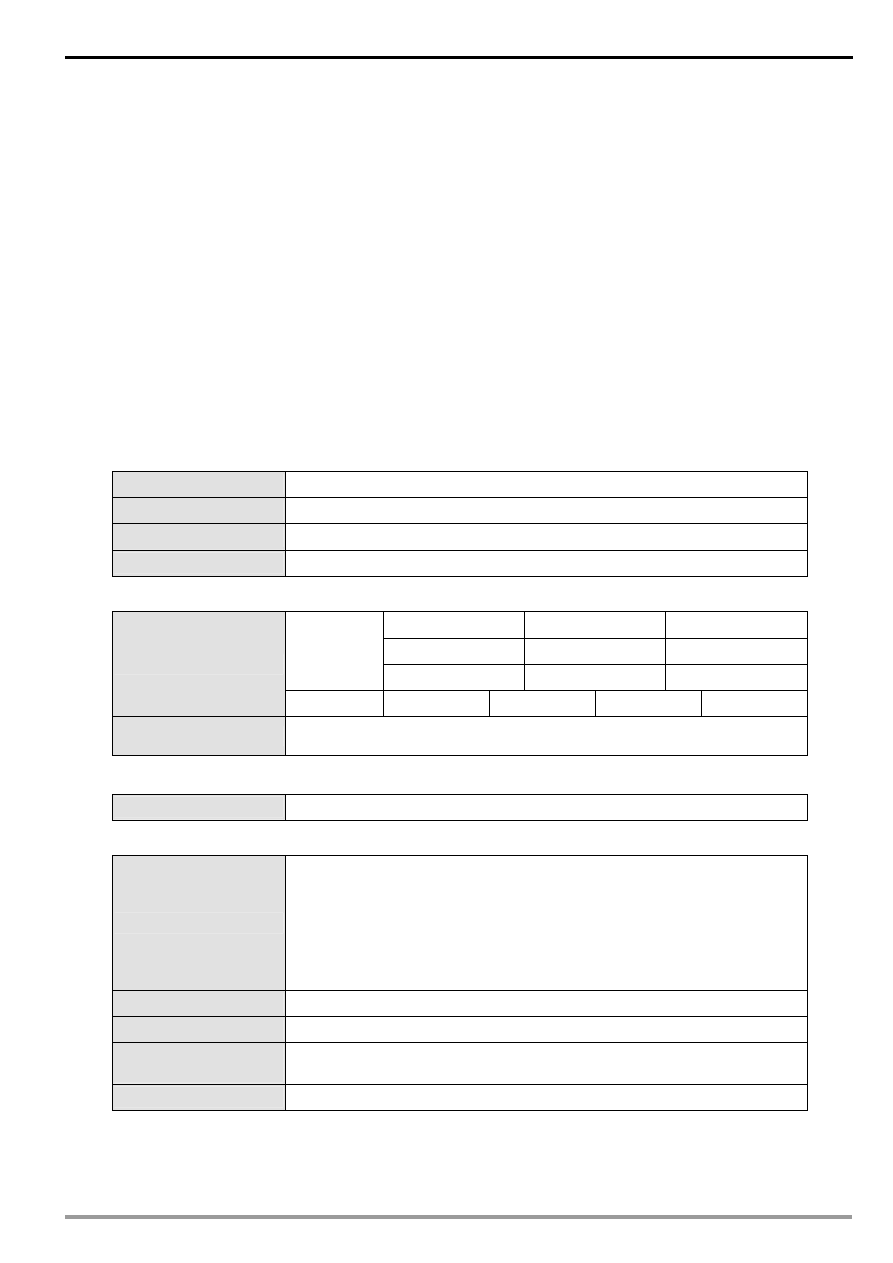
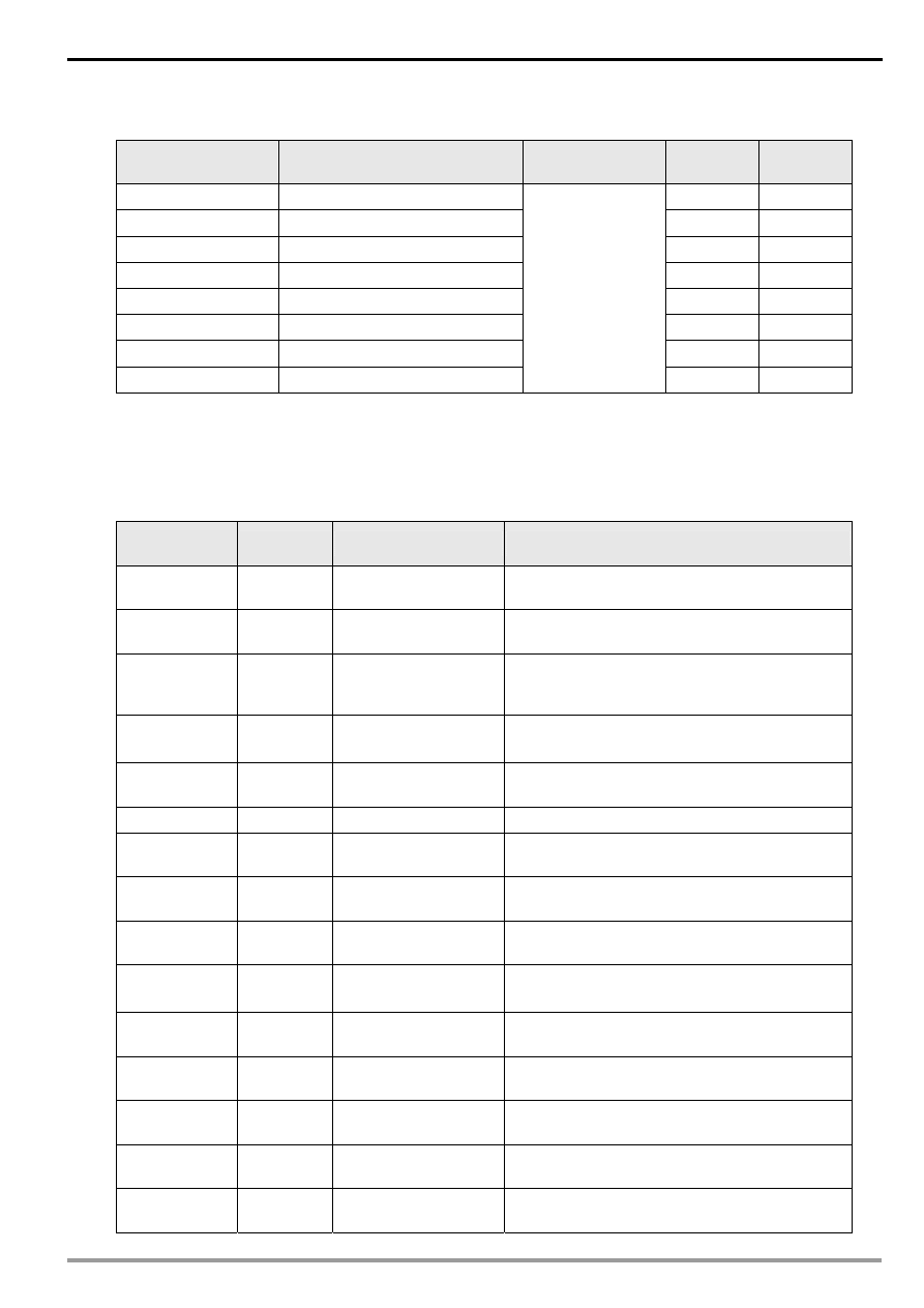
1.2 Specifications
DeviceNet connection
Transmission method
RS-485
Electrical isolation
500 VDC
Interface Removable
connector
(3Pin)
Transmission cable
2-wire twister shielded cablew8
Communication
7, E, 1
7, O, 2
8, O, 1
7, O, 1
7, N, 2
8, N, 1
ASCII
7, E, 2
8, E, 1
8, N, 2
Mode
RTU
8, E, 1
8, O, 1
8, N, 1
8, N, 2
Baud rates
1,200bps; 2,400bps; 4,800bps; 9,600bps; 19,200bps; 38,400bps;
57,600bps; 115,200bps
Electrical
specification
Power supply
24 VDC (-15% ~ 20%) (with DC input polarity reverse protection)
Environment
Noise immunity
ESD (IEC 61131-2, IEC 61000-4-2): 8KV Air Discharge,4KV Contact
Discharge
EFT (IEC 61131-2, IEC 61000-4-4): Power Line: 2KV, Digital I/O: 1KV
Analog & Communication I/O: 1KV
Damped-Oscillatory Wave: Power Line: 1KV, Digital I/O: 1KV
RS (IEC 61131-2, IEC 61000-4-3): 80MHz~1000MHz , 1.4GHz~2.0GHz ,
10V/m
Operation
0ºC ~ 55ºC (temperature); 50 ~ 95% (humidity); pollution degree 2
Storage
-25ºC ~ 70ºC (temperature); 5 ~ 95% (humidity)
Vibration/shock
resistance
Standard: IEC 61131-2、IEC 68-2-6 (TEST Fc)/IEC 61131-2 & IEC 68-2-27
(TEST Ea)
Certificates
IEC 61131-2, UL508
Modbus Remote I/O Communication Module RTU-485
DVP-PLC Application Manual
4
2
Product Profile & Outline
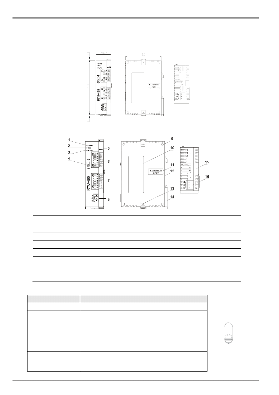
2.1 Dimension
2.2 Product
Profiles
1. POWER indicator
9. Mounting hole for extension module
2. RUN indicator
10. Nameplate
3. ALARM indicator
11. Extension port
4. RUN/STOP switch
12. DIN rail (35mm)
5. Communication indicator
13. Fastening hole for extension module
6. Address switch
14. DIN rail clip
7. Communication mode switch
15. Mounting rail for extension module
8. RS-485 communication port
16. Power input
2.3 RUN/STOP
Switch
RUN/STOP action
Explanation
RUN
Special module in RUN mode
RUN → STOP
1. Special module switches from RUN to STOP.
2. Output points on Slim DI/DO extension unit all turn Off.
STOP
1. Special module in STOP mode
2. Special module cannot be controlled by communication.
3. Slim DI/DO extension unit cannot be controlled by
communication.
STOP → RUN
1. Special module switches from STOP to RUN.
2. RTU-485 redetects the number of points in Slim DI/DO
and the number of special modules.
STO P
RUN
Modbus Remote I/O Communication Module RTU-485
DVP-PLC Application Manual
5
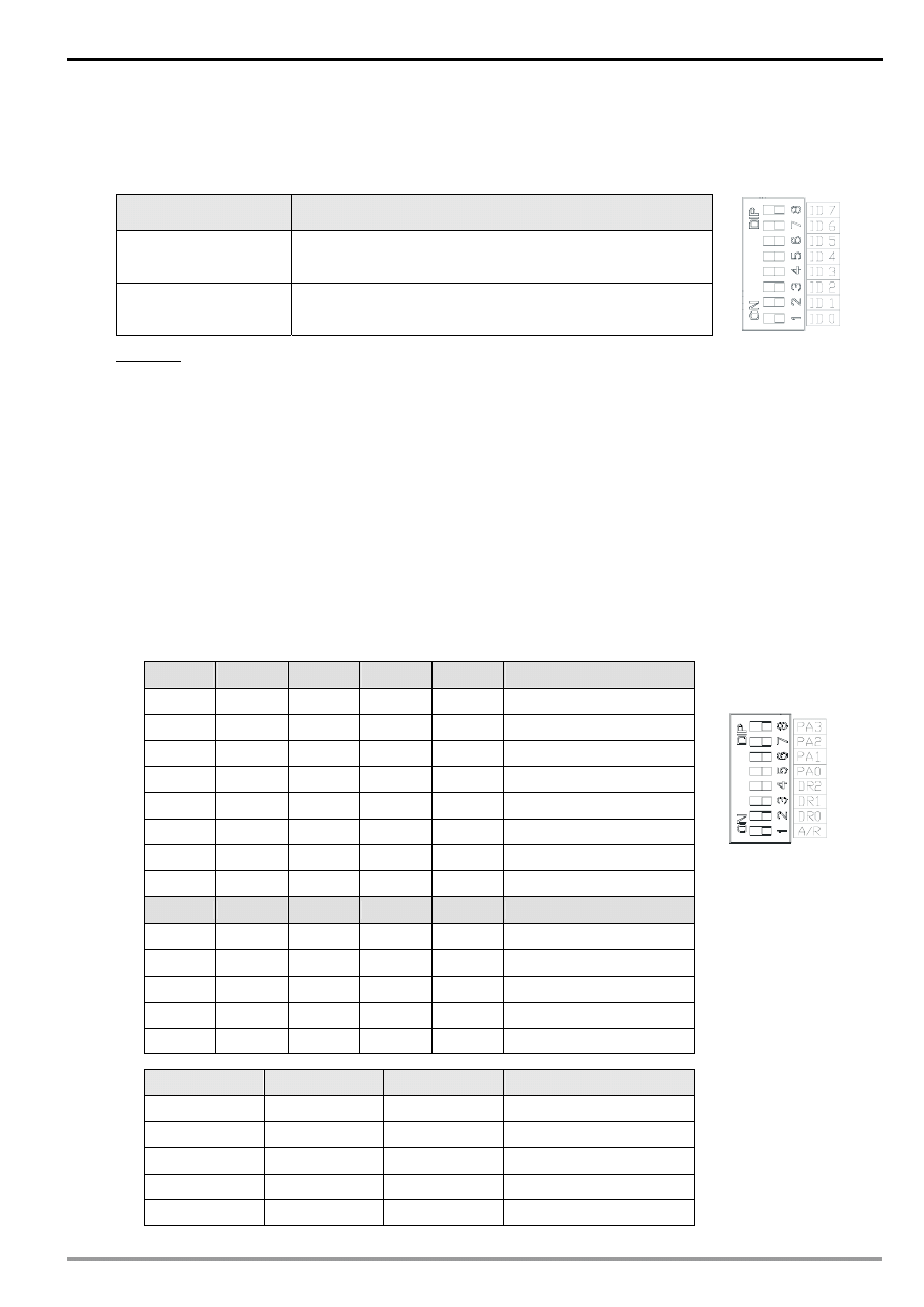
2.4 Address
Switch
The switch is used on setting up the communication address of RTU-485. Range: H’01 ~ H’F0 (decimal: 1 ~
240)
Switch setting
Content
H’01 ~ H’F0
Valid communication address
ID0 ~ ID7 are defined as: 2
0
, 2
1
, 2
2
, …2
6
, 2
7
H’00,
H’F1 ~ H’FF
Invalid communication address
Example: If you need to set the address of RTU-485 to 26, swich the DIP switch corresponding to ID4 to “ON”,
switch corresponding to ID3 to “ON” and switch corresponding to ID1 to “ON”.
Note:
z Please set up the address when the power of RTU-485 is switched off. After the setup is completed, re-power
RTU-485.
z When RTU-485 is operating, changing the setting of communication address will be invalid.
z Use slotted screwdriver to adjust the switch carefully in case you scratch the switch.
2.5
Communication Mode Switch
These switches are for:
z Setting up communication format (PA0 ~ PA3, A/R)
z Setting up baud rate (DR0 ~ DR2)
PA3
PA2
PA1
PA0
A/R
Format
OFF OFF OFF OFF ON
7,E,1,
ASCII
OFF OFF OFF ON ON
7,O,1,
ASCII
OFF OFF ON OFF ON
7,E,2,
ASCII
OFF OFF ON ON ON
7,O,2,
ASCII
OFF ON OFF OFF ON
7,N,2,
ASCII
OFF ON OFF ON ON
8,E,1,
ASCII
OFF ON ON OFF ON
8,O,1,
ASCII
OFF ON ON ON ON
8,N,1,
ASCII
PA3
PA2
PA1
PA0
A/R
Format
ON OFF OFF OFF ON
8,N,2,
ASCII
OFF ON OFF ON OFF
8,E,1,
RTU
OFF ON ON OFF OFF
8,O,1,
RTU
OFF ON ON ON OFF
8,N,1,
RTU
ON OFF OFF OFF OFF
8,N,2,
RTU
DR2
DR1
DR0
Baud rate (bps)
OFF OFF OFF
1,200
OFF OFF ON
2,400
OFF ON OFF
4,800
OFF ON ON
9,600
ON OFF OFF
19,200
Modbus Remote I/O Communication Module RTU-485
DVP-PLC Application Manual
6
ON OFF ON
38,400
ON ON OFF
57,600
ON ON ON
115,200
Note:
z Please set up the switch when the power is switched off. After the setup is completed, re-power RTU-485.
z When RTU-485 is operating, changing the setting of the switch will be invalid.
z Use slotted screwdriver to adjust the switch carefully in case you scratch the switch.
3 Basic
Operation
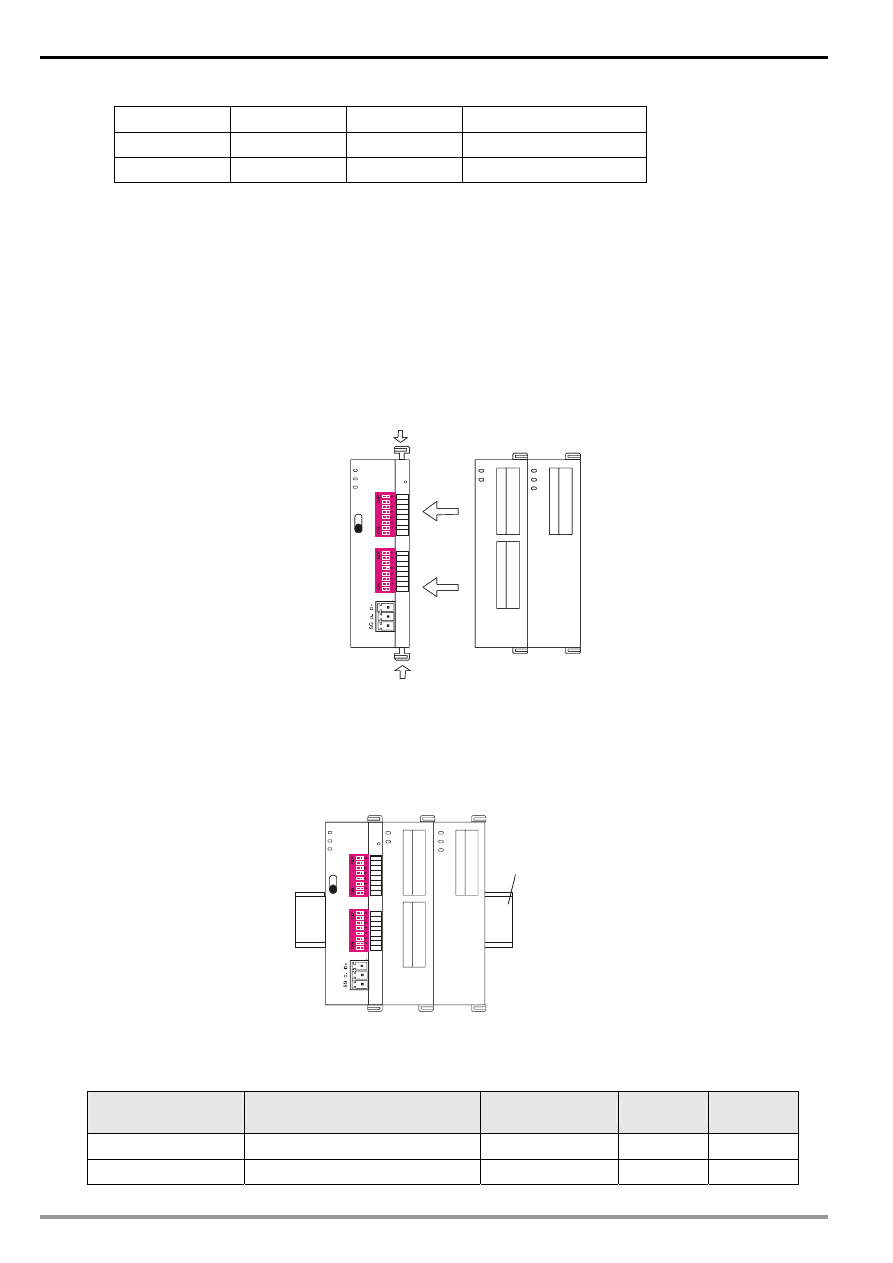
3.1
Connecting RTU-485 to DVP Slim DI/DO Extension Unit
z Open the fixing clips on top and bottom of RTU-485. Meet the extension port of Slim DI/DO with RTU-485.
z Press the fixing clips on top and bottom of Slim DIDO and check if the connection is fine.
R
T
U
-4
8
5
D
V
P
-1
6
S
P
D
V
P
-0
2
D
A
D
V
P
-1
6
S
P
D
V
P
-0
2
D
A
PA3
PA2
PA1
PA0
DR2
DR1
DR0
A/R
ID7
ID6
ID5
ID4
ID3
ID2
ID1
ID0
POWER
RUN
ALARM
RS- 485
R U N
S TO P
3.2
Installing RTU-485 and DVP Slim DI/DO on DIN Rail
z Use 35mm DIN rail.
z Open the DIN rail clip on RTU-485 and Slim DI/DO. Insert RTU-485 and Slim DI/DO onto the DIN rail.
z Clip up the DIN rail clips on RTU-485 and Slim DI/DO to fix them on the DIN rail, as shown below.
R
T
U
-4
8
5
PA3
PA2
PA1
PA0
DR2
DR1
DR0
A/R
ID7
ID6
ID5
ID4
ID3
ID2
ID1
ID0
POWER
RUN
ALARM
RS -485
D
V
P
-1
6
S
P
D
V
P
-0
2
D
A
35mm DIN rail
4
Areas for Special Functions
4.1
Areas in Slim DI/DO Extension Unit
Communication
address
Devices
Attribute
Data type
Length
H’0400 ~ H’047F
X: X000 ~ X177 (Octal)
R
bit
128 points
H’0500 ~ H’057F
Y: Y000 ~ Y177 (Octal)
R/W
bit
128 points
Modbus Remote I/O Communication Module RTU-485
DVP-PLC Application Manual
7
4.2
Areas in Special Module
Communication
address
Devices
Attribute
Data type
Length
H’1600 ~ H’1630
1
st
special module: CR0 ~ CR48
word
49
H’1640 ~ H’1670
2
nd
special module: CR0 ~ CR48
word
49
H’1680 ~ H’16B0
3
rd
special module: CR0 ~ CR48
word
49
H’16C0 ~ H’16F0
4
th
special module: CR0 ~ CR48
word
49
H’1700 ~ H’1730
5
th
special module: CR0 ~ CR48
word
49
H’1740 ~ H’1770
6
th
special module: CR0 ~ CR48
word
49
H’1780 ~ H’17B0
7
th
special module: CR0 ~ CR48
word
49
H’17C0 ~ H’17F0
8
th
special module: CR0 ~ CR48
Please refer to
theCR attribute of
each special
module.
word 49
Note:
Maximum 8 special modules are connectible to RTU-485. The first special module connected is the nearestone
on the right hand side of RTU-485, and so on.
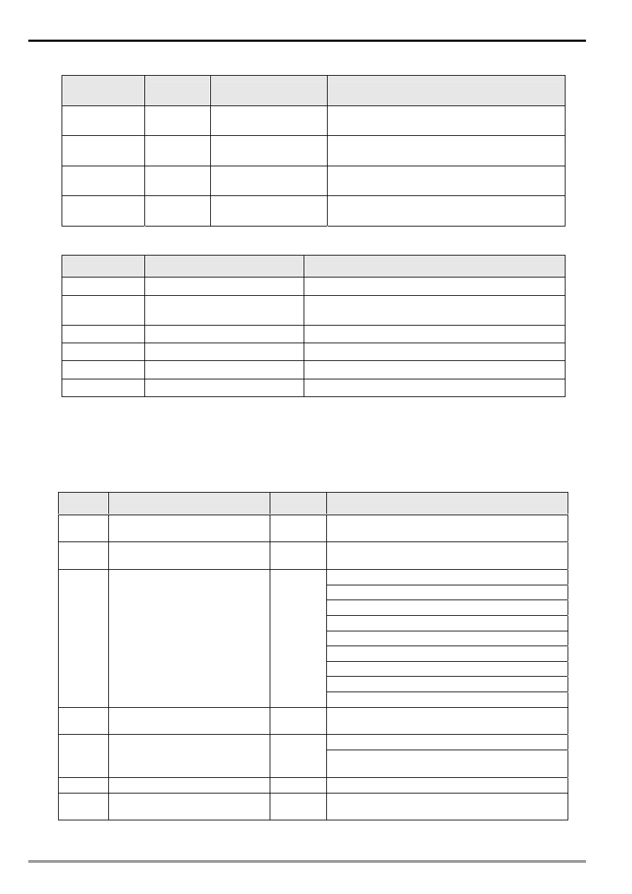
4.3 Special
Functions
Communication
address
Attribute
Content
Explanation
H’0000 R
Model
name
Set up by the system. Model code of RTU-485 =
H’0200.
H’0001 R
Firmware
version
The current firmware version is displayed in hex,
e.g. V0.1 is indicated as H’0010.
H’0002 R
Issue
date
The issue data of the firmware is displayed in
hex, e.g. H’1FD0 = K8150 indicates that the
firmware is issued on the morning of August 15.
H’0003 R/W
RUN/STOP
RTU-485
H’0003 = K1, RTU-485 RUN;
H’0003 = K0, RTU-485 STOP.
H’0004 R
Communication
format
Displaying the communication format of
RTU-485.
H’0005
R
Baud rate
Displaying the baud rate of RTU-485.
H’0006 R
Communication
address
Displaying the communication address of
RTU-485.
H’0007 R
Number of DI/DO
points
High byte stores the number of input points. Low
byte stores the number of output points.
H’0008 R
Error
code
Recording the current error. See 17.4.4 for the
meaing of error codes.
H’0009
R
Historical error code
The number of errors occurring.
Range: 0 ~ 32
H’0017 R
Number of special
modules
The number of special modules RTU-485
detects.
H’0018 R
Model code of the 1
st
special module
The model code of the 1
st
special module
connected to RTU-485.
H’0019 R
Model code of the 2
nd
special module
The model code of the 2
nd
special module
connected to RTU-485.
H’001A R
Model code of the 3
rd
special module
The model code of the 3
rd
special module
connected to RTU-485.
H’001B R
Model code of the 4
th
special module
The model code of the 4
th
special module
connected to RTU-485.
Modbus Remote I/O Communication Module RTU-485
DVP-PLC Application Manual
8
Communication
address
Attribute
Content
Explanation
H’001C R
Model code of the 5
th
special module
The model code of the 5
th
special module
connected to RTU-485.
H’001D R
Model code of the 6
th
special module
The model code of the 6
th
special module
connected to RTU-485.
H’001E R
Model code of the 7
th
special module
The model code of the 7
th
special module
connected to RTU-485.
H’001F R
Model code of the 8
th
special module
The model code of the 8
th
special module
connected to RTU-485.
4.4 Error
Codes
Code
Indication
Explanation
0001
Incorrect function code
RTU-485 does not support this function code.
0002
Incorrect operand address
The address of a certain device is not within the
range, orthe data written into it are incorrect.
0003
Incorrect data
The data read/written exceed the maximum length.
0004
RTU-485 STOP
RTU-485 in STOP mode.
000B
Incorrect communication format
The length of data received by RTU-485 is too short.
000C
Incorrect communication format
The length of data received by RTU-485 is too long.
5
Function Codes RTU-485 Supports
RTU-485 complies with the standard Modbus protocol, supporting 7 function codes, which are H’01, H’02, H’03,
H’05, H’06, H’0F and H’10. Please refer to the standard Modbus protocol for the specific data format of each
function code.
Code
Function
Data type
Applicable address
H’01
Reading the output status of bit
device.
bit
DO area: H’0500 ~ H’057F
H’02
Reading the input status of bit
device
word bit
DI area: H’0400 ~ H’047F
Area for special functions: H’0000 ~ H’001F
CR for the 1
st
special module: H’1600 ~ H’1630
CR for the 2
nd
special module: H’1640 ~ H’1670
CR for the 3
rd
special module: H’1680 ~ H’16B0
CR for the 4
th
special module: H’16C0 ~ H’16F0
CR for the 5
th
special module: H’1700 ~ H’1730
CR for the 6
th
special module: H’1740 ~ H’1670
CR for the 7
th
special module: H’1780 ~ H’16B0
H’03 Reading
register
bit
CR for the 8
th
special module: H’17C0 ~ H’17F0
H’05
Writing single datum into bit
device
bit
DO area: H’0500 ~ H’057F
RTU-485 RUN/STOP mode: H’0003
H’06
Writing single datum into register
word
Applicable to CR with R/W attribute in the 1
st
~ 8
th
special module
H’0F
DO area: H’0500 ~ H’057F
H’10
Writing many data into bit device
bit
Applicable to CR with R/W attribute in the 1
st
~ 8
th
special module
Modbus Remote I/O Communication Module RTU-485
DVP-PLC Application Manual
9
6
Application of RTU-485
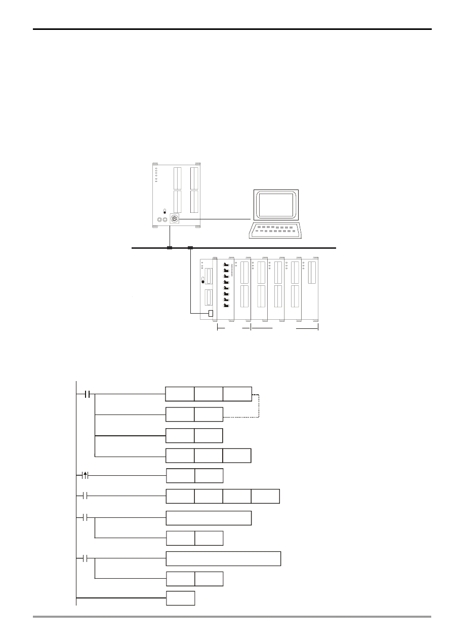
6.1 Connection between RTU-485 and Master Device
As a standard Modbus slave, RTU-485 is compatible with pther programmable logic controllers which also
comply with Modbus protocol. The example here takes DVP-SV PLC as the master. The PC downloads the
ladder diagram to DVP-SV through RS-232 communication port (COM1). When DVP-SV executes the ladder
diagram program, it will send out Modbus command through RS-485 communication port (COM2) and conduct
remote I/O control on RTU-485. See the figure on the next page for the connection between RTU-485 and the
master device:
DVP28SV
RUN
STOP
D
V
P
-0
2
D
A
D
V
P
-0
8
S
T
D
V
P
-1
6
S
P
D
V
P
-0
4
A
D
D
V
P
-0
4
T
C
D
V
P
-0
4
P
T
R
T
U
-4
8
5
RS-485
CO M2
RTU-485
Slim
DI/DO
Special
module
DVP-SV
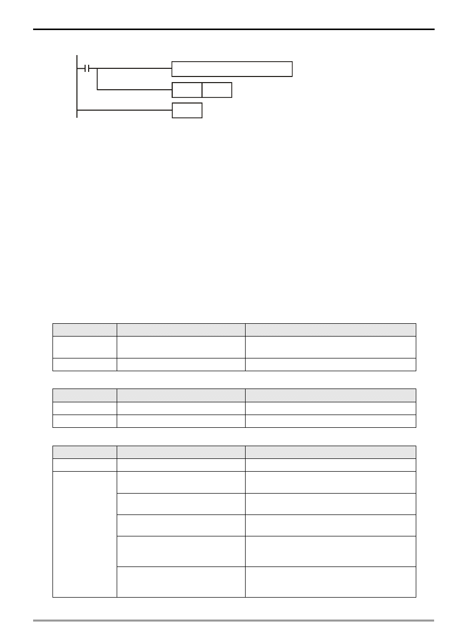
6.2 Application Example
Example
1
¡ The station No. of RTU-485 is “1”. Write “H’0001” into CR#6 of the 1
st
special module.
Set up communication protocol
9600,7,E,1,ASCII
MOV
K300
D1129
M1002
SET
M1120
M0
SET
M1122
M0
MODWR
K1
H1606
H0001
END
RST
M1143
M1123
RST
M1123
M1129
RST
M1129
Retain communication protocol
Set up communication time-out 300ms
Set up sending request
Write H0001 into CR#6 of
the 1 special module
st
Process received data
Receiving of data is completed.
The flag is reset.
Process communication time-out
MOV
H86
D1120
Modbus Remote I/O Communication Module RTU-485
DVP-PLC Application Manual
10
¡ Explanations
1. You have to set up the communication format at the beginning of the program. The communication
format for the master and slave has to be consistent, e.g. you can see the format is 9600, 7, E, 1,
ASCII from this example.
2. After setting up the communication format, you have to set up the communication retention device
M1120 of COM2.
3. After M0 is On, set up the sending request flag, and the master device will send out a request
message to RTU-485 and write H’0001 into CR#6 of the 1
st
special module on the right hand side of
RTU-485.
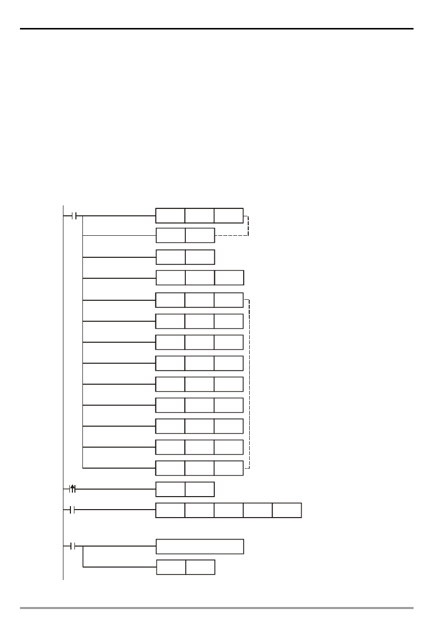
Example
2
¡ The station No. of RTU-485 is “1”. Set up Y0 of the Slim DI/DO on the right hand side of RTU-485.
MOV
K300
D1129
M1002
MOV
H86
SET
M1120
RST
M1143
MOV
MOV
MOV
H303A
D100
H3031
D101
H3035
D102
MOV
MOV
H3035
D103
H4630
D104
MOV
MOV
H3046
D105
H4630
D106
MOV
MOV
H
D107
HA
D108
M0
SET
M1122
M0
RS
D100
K17
D120
K17
M1123
RST
M1123
PLC sends out
01 05 05 00 FF 00 F6 CR LF
":
"
D36
Set up communication protocol
9600, 7, E, !, ASCII
Retain communication protocol
Set up communication time-out 300ms
to RTU-485
Set up sending request
When M0 = On, the 17 words in D100 ~ D108 will be sent out.
The 17 words responded by RTU-485 will be stored in D120 ~ D128 by the master.
Process received data
Receiving of data is completed.
The flag is reset.
D1120
Modbus Remote I/O Communication Module RTU-485
DVP-PLC Application Manual
11
END
M1129
RST
M1129
Process communication time-out
Explanations
1. You have to set up the communication format at the beginning of the program. The communication
format for the master and slave has to be consistent, e.g. you can see the format is 9600, 7, E, 1,
ASCII from thie example.
2. The master PLC sends out data to RTU-485 in ASCII, e.g. the high byte “30” in D100 refers to “0” and
low bytes “3A” refers to the head code “:”.
3. After M0 is On, set up M1122. At this moment, the master PLC will send the 17 words of data in D100
~ D108 to RTU-485 by RS instruction. The data in low words will be sent first. The master PLC will
store the responding message sent by RTU-485 into D120 ~ D128.
7
LED Indicator & Trouble-shooting
There are four LED indicators on RTU-485, which are POWER, RUN, ALARM and RS-485, for displaying the
working status and communication connection status of RTU-485.
7.1 POWER
LED
LED status
Indication
How to correct
Off
No power, or the power is abnormal.
Check the power of RTU-485 and see if the
connection is normal.
Green light On
The power of RTU-485 is normal.
--
7.2 RUN
LED
LED status
Indication
How to correct
Off
RTU-485 is in STOP status.
--
Green light On
RTU-485 is in RUN status.
--
7.3 ALARM
LED
LED status
Indication
How to correct
Off
The power is in low voltage.
Check if the power of RTU-485 is normal.
Incorrect communication format for
RTU-485
Check if the communication format for RTU-485
is correct.
Incorrect communication address for
RTU-485
Check if the communication address of RTU-485
is valid.
RTU-485 is not connected to
extension module.
Check if RTU-485 is connected to extension
module normally.
More than 8 extension modules
connected to RTU-485.
Check and make sure that the number of
extension modules connected to RTU-485 is
less than 8.
Red light On
The number of points on Slim DI/DO
connected to RTU-485 exceeds the
range.
Check and make sure the number of input points
on Slim DI/DO connected to RTU-485 is less
than 128, and output points also less than 128.

Modbus Remote I/O Communication Module RTU-485
DVP-PLC Application Manual
12
7.4 RS-485
LED
LED status
Indication
How to correct
Off
RTU-485 is not communicating with
the master device.
--
Red light flashing
RTU-485 is communicating to the
master device normally.
--
Wyszukiwarka
Podobne podstrony:
manual mechanika 2 2 id 279133 Nieznany
Active Listening en id 51008 Nieznany (2)
BPMN2 0 Poster EN id 92566 Nieznany (2)
mizan Z2 MECH EN id 778695 Nieznany
Agenda en id 52847 Nieznany (2)
55 en id 41488 Nieznany
cat 6AD en id 108772 Nieznany
iecp en id 209519 Nieznany
26 en id 31374 Nieznany (2)
origomag c140 manual PL id 3403 Nieznany
KS SF 12 006 EN id 252123 Nieznany
Makros powerPLmC E30 en id 1627 Nieznany
lab11 RapidPrototyping EN id 25 Nieznany
iteiit21v9n1 en id 220860 Nieznany
25 en id 31087 Nieznany (2)
Dyrektywa PED 97 23 CE EN id 14 Nieznany
KUKA RSI rsi r20 en id 744255 Nieznany
mizan Z3 MECH EN id 778696 Nieznany
więcej podobnych podstron