DRIVE AXLE, SPEED
REDUCER, AND
DIFFERENTIAL
J2.00-3.20XM
(J40-60XM, J40-60XM
2
) [A216];
J2.00-3.20XM (J40-65Z) [A416]
PART NO. 897670
1400 SRM 575

SAFETY PRECAUTIONS
MAINTENANCE AND REPAIR
• When lifting parts or assemblies, make sure all slings, chains, or cables are correctly
fastened, and that the load being lifted is balanced. Make sure the crane, cables, and
chains have the capacity to support the weight of the load.
• Do not lift heavy parts by hand, use a lifting mechanism.
• Wear safety glasses.
• DISCONNECT THE BATTERY CONNECTOR before doing any maintenance or repair
on electric lift trucks. Disconnect the battery ground cable on internal combustion lift
trucks.
• Always use correct blocks to prevent the unit from rolling or falling. See HOW TO PUT
THE LIFT TRUCK ON BLOCKS in the Operating Manual or the Periodic Mainte-
nance section.
• Keep the unit clean and the working area clean and orderly.
• Use the correct tools for the job.
• Keep the tools clean and in good condition.
• Always use HYSTER APPROVED parts when making repairs. Replacement parts
must meet or exceed the specifications of the original equipment manufacturer.
• Make sure all nuts, bolts, snap rings, and other fastening devices are removed before
using force to remove parts.
• Always fasten a DO NOT OPERATE tag to the controls of the unit when making repairs,
or if the unit needs repairs.
• Be sure to follow the WARNING and CAUTION notes in the instructions.
• Gasoline, Liquid Petroleum Gas (LPG), Compressed Natural Gas (CNG), and Diesel fuel
are flammable. Be sure to follow the necessary safety precautions when handling these
fuels and when working on these fuel systems.
• Batteries generate flammable gas when they are being charged. Keep fire and sparks
away from the area. Make sure the area is well ventilated.
NOTE: The following symbols and words indicate safety information in this
manual:
WARNING
Indicates a condition that can cause immediate death or injury!
CAUTION
Indicates a condition that can cause property damage!

Drive Axle, Speed Reducer, and Differential
Table of Contents
TABLE OF CONTENTS
General ...............................................................................................................................................................
Description .........................................................................................................................................................
Drive Axle, Speed Reducer, and Differential Repair........................................................................................
Remove ...........................................................................................................................................................
Disassemble ...................................................................................................................................................
Clean ..............................................................................................................................................................
Inspect ............................................................................................................................................................
Assemble ........................................................................................................................................................
Install .............................................................................................................................................................
Torque Specifications .........................................................................................................................................
Troubleshooting..................................................................................................................................................
This section is for the following models:
J2.00-3.20XM (J40-60XM, J40-60XM
2
) [A216];
J2.00-3.20XM (J40-65Z) [A416]
©2005 HYSTER COMPANY
i

"THE
QUALITY
KEEPERS"
HYSTER
APPROVED
PARTS
1400 SRM 575
Description
General
This section has the description and repair procedures for the differential, speed reducer, drive axle, and the
mounts for the axle housing.
Description
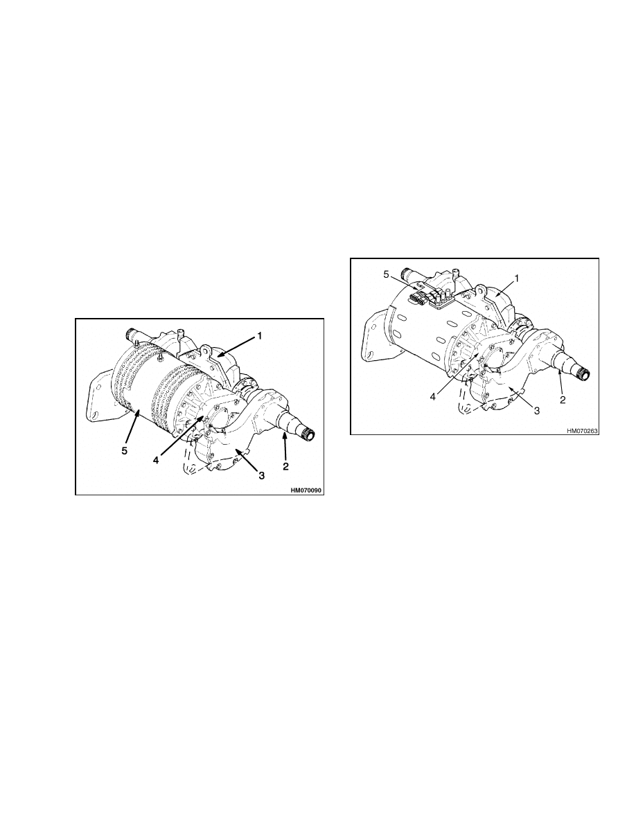
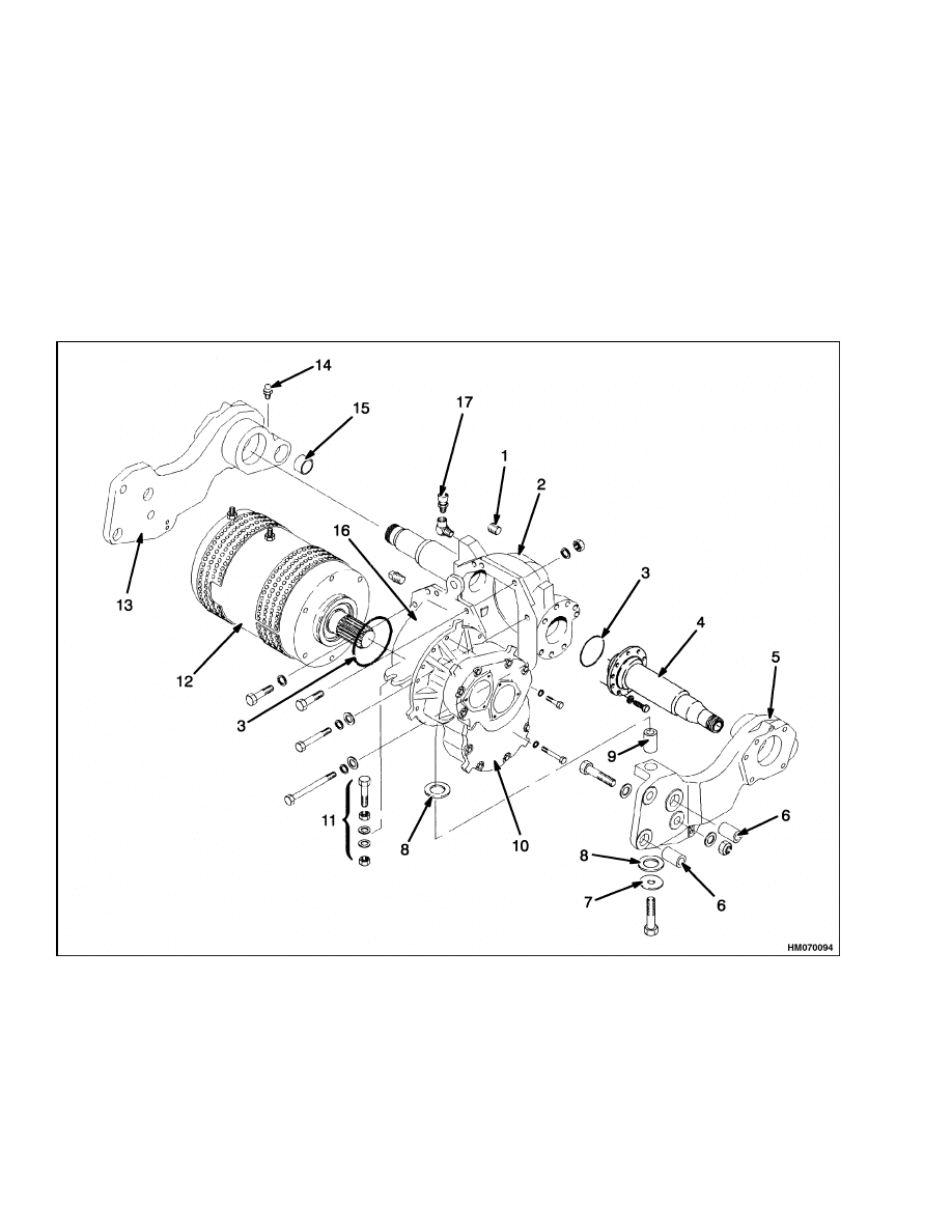
The drive unit assembly is fastened to the frame of
the lift truck by the axle mounts. See Figure 1 and
Figure 2. The outer ends of the axle housings are
the spindles for the wheel bearings. The cups for the
wheel bearings are pressed into the wheel hubs. The
nut on the end of the spindle holds and adjusts the
preload on the wheel bearings. The axle shafts are
fastened to the hubs by capscrews. Studs and nuts
fasten the wheel to the hub and brake drum. The
back plate and brake assemblies are fastened to the
axle mounts.
1.
DIFFERENTIAL
2.
SPINDLE (AXLE
HOUSING)
3.
AXLE MOUNT
4.
SPEED REDUCER
5.
TRACTION MOTOR
Figure 1. Drive Unit Assembly J2.00-3.20XM
(J40-60XM, J40-60XM
2
) (A216)
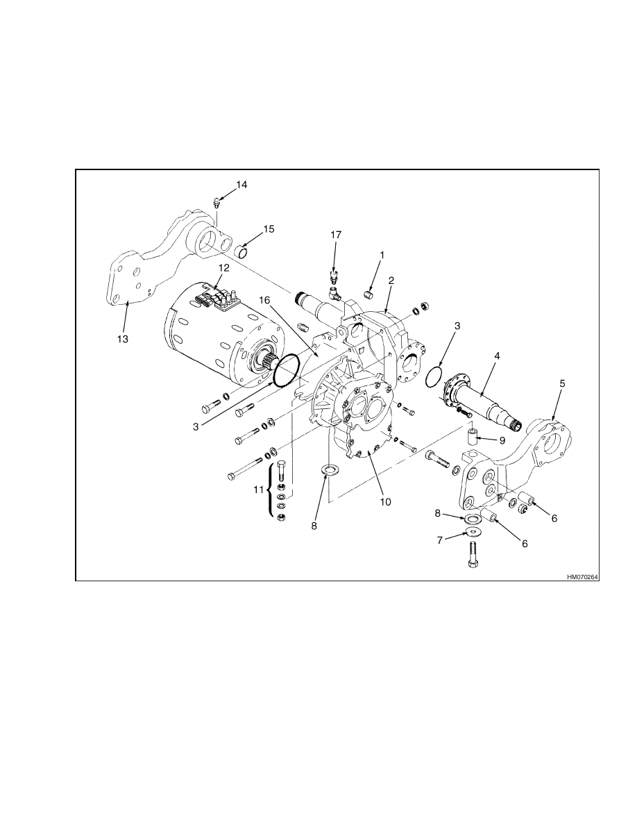
The speed reducer and differential are assembled as
a single unit. See Figure 8. The pinion in the speed
reducer engages the splines on the shaft of the trac-
tion motor. The cluster gear transfers power from
the pinion to the reduction gear. The reduction gear
is engaged with the drive gear on the differential.
1.
DIFFERENTIAL
2.
SPINDLE (AXLE
HOUSING)
3.
AXLE MOUNT
4.
SPEED REDUCER
5.
TRACTION MOTOR
Figure 2. Drive Unit Assembly J2.00-3.20XM
(J40-65Z) (A416)
1
Drive Axle, Speed Reducer, and Differential Repair
1400 SRM 575
Drive Axle, Speed Reducer, and Differential Repair
REMOVE
NOTE: The traction motor can be removed as a sep-
arate unit. See the section Frame 100 SRM 582 for
the procedure to remove the traction motor.
WARNING
The lift truck must be put on blocks for some
types of maintenance and repair. The removal
of the following assemblies will cause large
changes in the center of gravity: attachment,
mast, drive axle, battery, and the counter-
weight. When the lift truck is put on blocks,
put additional blocks in the following posi-
tions:
a. Before removing the drive axle, put blocks
under the counterweight so the lift truck
cannot tip backward.
b. Before removing the battery or counter-
weight, put blocks under the mast assem-
bly so the lift truck cannot tip forward.
Put the lift truck on blocks only if the surface
is solid, even, and level. Make sure that any
blocks used to support the lift truck are solid,
one-piece units.
1.
Disconnect the battery connector.
2.
Remove the mast assembly as described in Mast,
Repairs 4000 SRM 522.
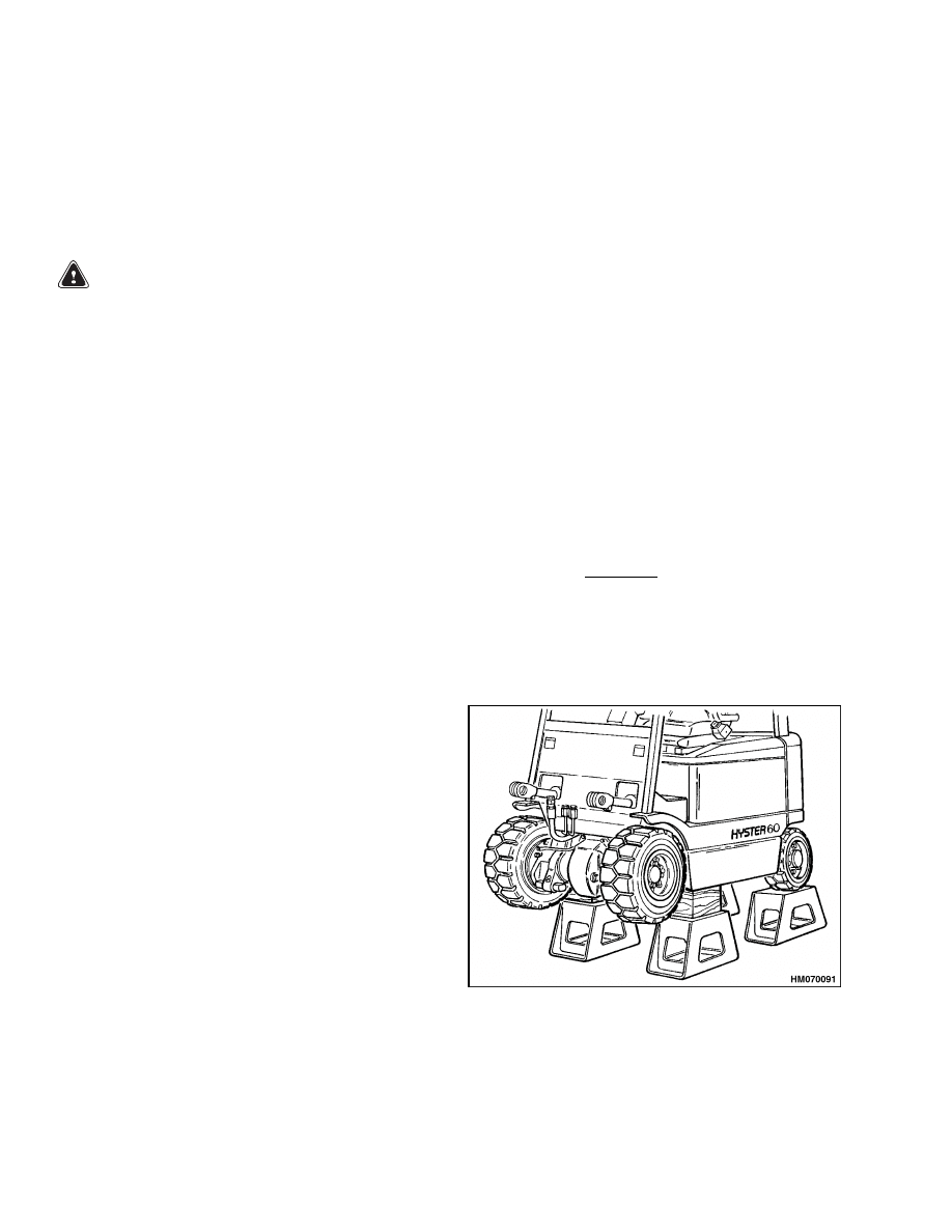
3.
Use a crane and chains to put the lift truck on
blocks as shown in Figure 3. Make sure the crane
has the capacity to lift the weight of the lift truck.
See the nameplate for the weight of the lift truck.
4.
Remove the floor plates.
Remove the drive
wheels. Disconnect the brake lines to the wheel
cylinders. Put caps on the open fittings.
5.
Disconnect the parking brake cables from the
levers of the service brakes. Drain the oil from
the differential.
6.
Put a floor jack under the drive unit assembly.
Make sure the drive unit assembly has stability;
then, remove the nuts and bolts from the axle
mounts. Remove the alignment pins from the
frame. The alignment pins can be a tight fit. See
the procedures in Figure 4 and Figure 5. Slide
the drive unit assembly from the lift truck.
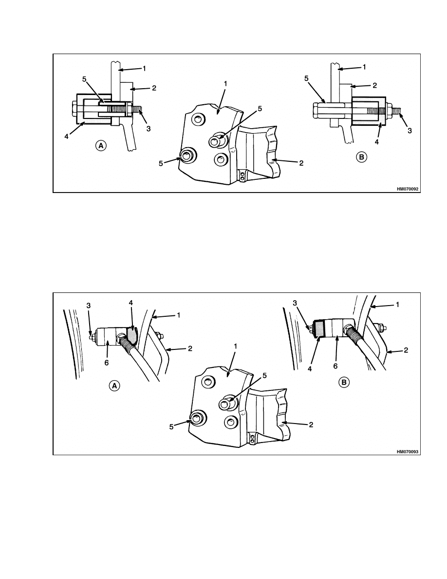
a. Method 1. See Figure 4.
(1)
Use a grade 8 bolt that is the maximum
diameter possible and long enough to go
through the spacer (cup) and pin. Put
a washer and nut on the threaded end
against the alignment pin. The washer
and nut must be smaller than the holes
in the frame and axle mount.
(2)
Install the spacer and bolt through the
pin from the frame side. Use a wrench
to pull the alignment pin out of (re-
moval) or into (installation) the axle
mount and frame members.
b. Method 2. See Figure 5.
(1)
Use a threaded rod (bolt) as described
in Method 1, but long enough to go
through the alignment pin,
spacer
(cup), and hydraulic cylinder with a
hollow piston. The washer and nut on
the end of the bolt must be smaller than
the holes in the frame and axle mount
when the pin is removed.
Figure 3. Put Lift Truck on Blocks
2
1400 SRM 575
Drive Axle, Speed Reducer, and Differential Repair
A. REMOVAL
B. INSTALLATION
1.
FRAME
2.
AXLE MOUNT
3.
BOLT
4.
SPACER (CUP)
5.
ALIGNMENT PIN
Figure 4. Axle Mount Arrangement (Method 1)
(2)
Install the spacer (cup), hydraulic cylin-
der, and threaded rod through the
alignment pin from the frame side.
Operate the hydraulic cylinder in the
direction away from the frame and pull
the pin out of (removal) or into (in-
stallation) the axle mount and frame
members.
A. REMOVAL
B. INSTALLATION
1.
FRAME
2.
AXLE MOUNT
3.
BOLT
4.
SPACER (CUP)
5.
ALIGNMENT PIN
6.
HYDRAULIC CYLINDER (WITH
HOLLOW PISTON)
Figure 5. Axle Mount Arrangement (Method 2)
3
Drive Axle, Speed Reducer, and Differential Repair
1400 SRM 575
DISASSEMBLE
1.
Remove the axle shafts. See Figure 6 and Fig-
ure 7. If necessary, remove the brake assemblies
as described in the section Brake System 1800
SRM 566.
2.
Remove the capscrew that holds the right-hand
axle mount to the speed reducer housing. Re-
move the axle mounts from the axle housing.
3.
Remove the expansion plug from the differential
housing. Remove the nuts and washer from the
reduction gear.
4.
Remove the capscrews that hold the speed re-
ducer housing to the differential housing. Sep-
arate the housings.
5.
Remove the bearing caps from the speed reducer
housing. Remove the capscrews that hold the
halves of the speed reducer housing together.
Separate the housings.
1.
OIL LEVEL PLUG
2.
DRIVE AXLE HOUSING
3.
O-RING
4.
SPINDLE
5.
RH AXLE MOUNT
6.
ALIGNMENT PIN
7.
WASHER
8.
ISOLATOR
9.
SPACER
10. SPEED REDUCER HOUSING
11. NUTS AND BOLT (MOTOR
SUPPORT)
12. DC TRACTION MOTOR
13. LH AXLE MOUNT
14. GREASE FITTING
15. BUSHING
16. DIFFERENTIAL HOUSING
17. BREATHER
Figure 6. Drive Unit Parts J2.00-3.20XM (J40-60XM, J40-60XM
2
) (A216)
4
1400 SRM 575
Drive Axle, Speed Reducer, and Differential Repair
6.
Remove the gears, bearings, and shims from the
speed reducer housing.
7.
Remove the lock plates for the adjustment nuts
for the differential. Remove the capscrews for the
differential bearing caps. Remove the bearing
caps and adjustment nuts.
8.
Remove the drive gear from the differential case.
See Figure 8. If necessary, disassemble the dif-
ferential. See Figure 9.
1.
OIL LEVEL PLUG
2.
DRIVE AXLE HOUSING
3.
O-RING
4.
SPINDLE
5.
RH AXLE MOUNT
6.
ALIGNMENT PIN
7.
WASHER
8.
ISOLATOR
9.
SPACER
10. SPEED REDUCER HOUSING
11. NUTS AND BOLT (MOTOR SUPPORT)
12. AC TRACTION MOTOR
13. LH AXLE MOUNT
14. GREASE FITTING
15. BUSHING
16. DIFFERENTIAL HOUSING
17. BREATHER
Figure 7. Drive Unit Parts J2.00-3.20XM (J40-65Z) (A416)
5

Drive Axle, Speed Reducer, and Differential Repair
1400 SRM 575
CLEAN
WARNING
Always wear safety glasses.
Cleaning solvents may be flammable and toxic
and can cause severe skin irritation. When us-
ing cleaning solvents, always comply with the
solvent manufacturer’s recommended safety
precautions.
Compressed air can move particles so that they
cause injury to the user or to other personnel.
Make sure that the path of the compressed air
is away from all personnel.
Wear protective
goggles or a face shield to prevent injury to the
eyes.
Clean the parts of the drive axle with a cleaning sol-
vent. Dry the parts with compressed air.
1.
DRIVE GEAR
2.
DIFFERENTIAL
3.
DIFFERENTIAL BEARING CAP
4.
ADJUSTMENT NUT
5.
CAPSCREW AND LOCK
PLATE
6.
SPEED REDUCER HOUSING
7.
BEARING CUP
8.
BEARING CONE
9.
CLUSTER GEAR
10. SHIMS
11. BEARING CAP
12. O-RING
13. REDUCTION GEAR
14. PINION
15. ALIGNMENT PIN
16. DIFFERENTIAL HOUSING
17. EXPANSION PLUG
18. LOCK NUT
19. LOCK RING
20. BEARING LOCK NUT
Figure 8. Speed Reducer and Differential Assembly
6
1400 SRM 575
Drive Axle, Speed Reducer, and Differential Repair
INSPECT
1.
Check the gears for wear or damage. Inspect the
spider gears and axle gears for worn teeth. In-
spect the cross for wear where the gears turn.
The cross and the holes for the cross in the dif-
ferential case must fit tightly.
2.
Inspect the bearings and bearing surfaces for
damage.
3.
The mounts must turn freely on the axle hous-
ing. The splines for the axle shafts must not be
damaged.
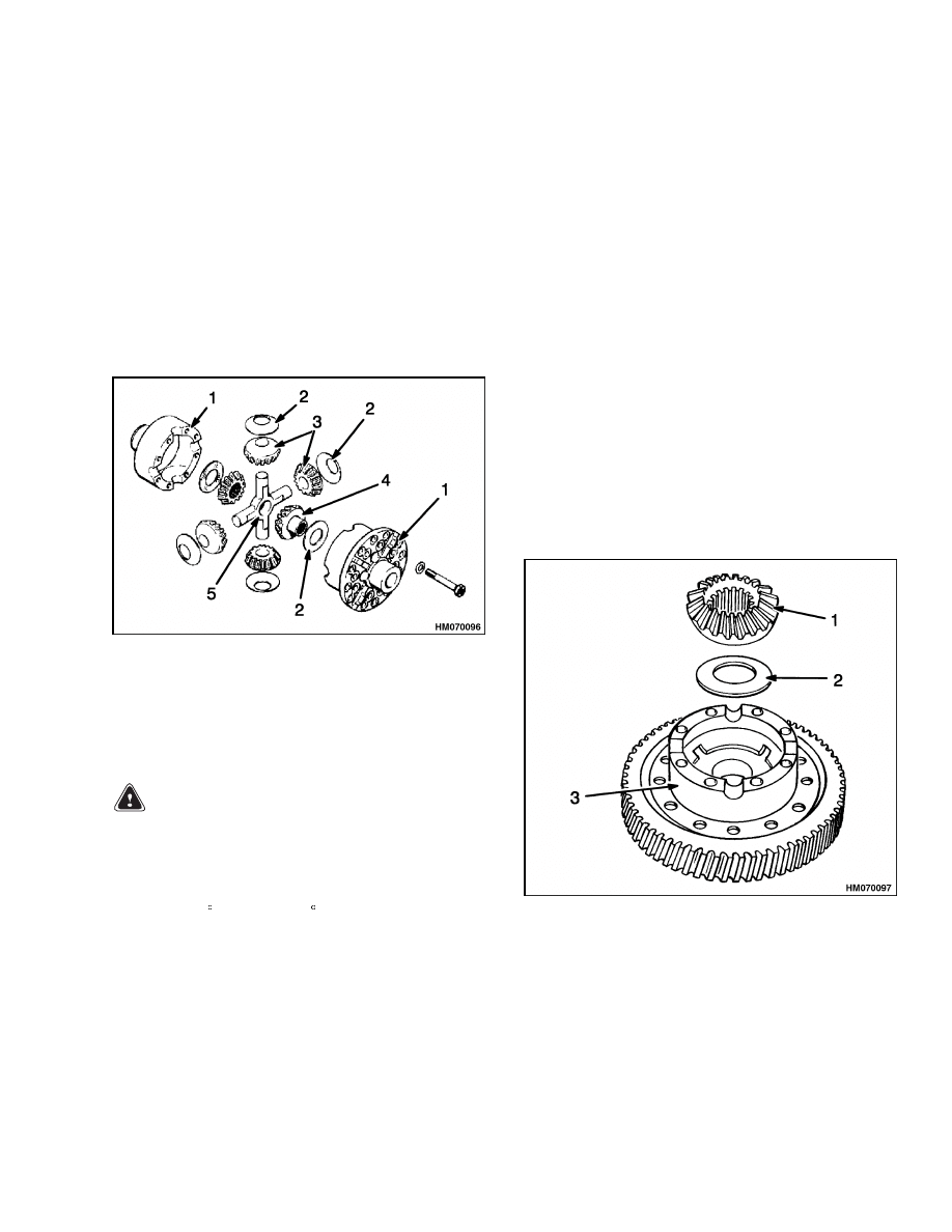
1.
DIFFERENTIAL
CASE
2.
THRUST WASHER
3.
PINION
4.
SIDE GEAR
5.
SPIDER
Figure 9. Differential
ASSEMBLE
WARNING
Hot parts. Wear protective clothing and gloves
to prevent burns.
1.
If the drive gear was removed from the differen-
tial case, put the drive gear in hot water that is
82 to 105 C (180 to 220 F) for approximately 10
minutes. Remove the drive gear from the water
and put it on the differential case. Do not use
a press or a hammer to install the drive gear.
Install the twelve capscrews and special hard-
ened washers. Tighten the capscrews to 111 N•m
(82 lbf ft). Make sure the drive gear is in the cor-
rect position against the flange of the differential
case.
2.
Lubricate and install a side gear and thrust
washer in the differential case as shown in Fig-
ure 10. Make sure the side of the thrust washer
with dents is toward the side gear.
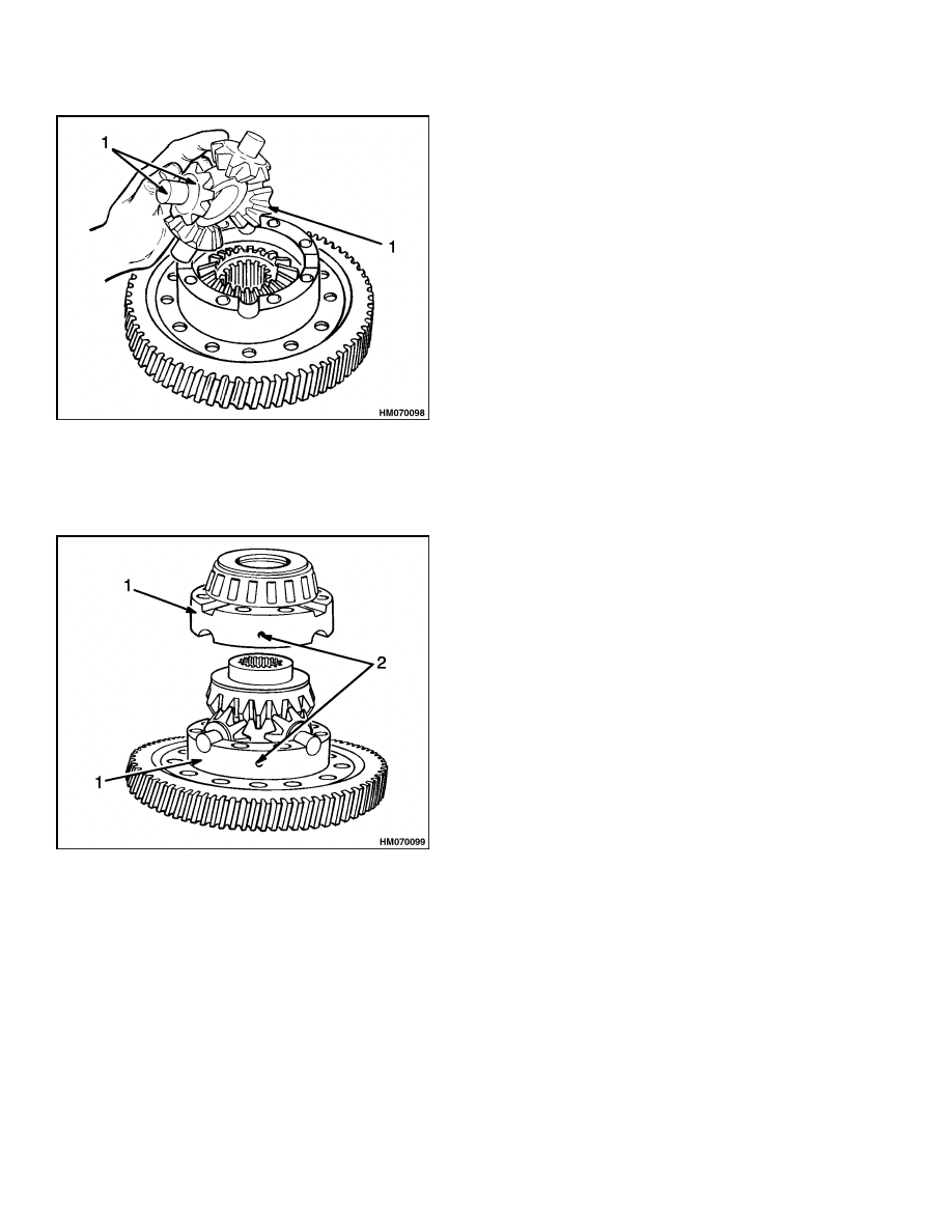
3.
Install the spider (cross), differential pinions,
and thrust washers into the differential case as
shown in Figure 11.
4.
Install the second side gear and thrust washer
over the spider and differential pinions as shown
in Figure 12.
Put the second half of the dif-
ferential case over the first half and the gears
as shown in Figure 12. Make sure the marks
are aligned. Install four of the capscrews in a
cross pattern. Tighten the capscrews to 50 N•m
(37 lbf ft). Install the remaining capscrews and
tighten them in a cross pattern.
5.
Install the bearing cones on the differential case.
1.
SIDE GEAR
2.
THRUST WASHER
3.
DIFFERENTIAL CASE
Figure 10. Install Side Gear and Thrust Washer
7
Drive Axle, Speed Reducer, and Differential Repair
1400 SRM 575
1.
SPIDER, DIFFERENTIAL PINIONS, AND
THRUST WASHERS
Figure 11. Spider (Cross), Pinions, and Thrust
Washers Installation
1.
DIFFERENTIAL CASE
2.
ALIGNMENT MARKS
Figure 12. Second Half of Differential Case
Installation
6.
Apply axle lubricant on the inner diameter of the
bearing cups and on both bearing cones that are
installed on the differential. Do not permit lubri-
cant on the outer diameter of the bearing cups or
the bearing bores of the housing.
7.
Install the differential assembly into the hous-
ing. The bearing cups must fit correctly into the
bores of the housing.
8.
Install the two bearing adjustment nuts into po-
sition in the housing bores. Use your hand to
tighten each adjustment nut against the bearing
cup. Use the adjustment nuts to put the drive
gear in the correct location as shown in Figure 13.
9.
Align the marks on the bearing caps with the
marks on the housing. See Figure 14. Tighten
the capscrews for the bearing caps to 95 to
110 N•m (70 to 81 lbf ft).
10. Tighten the adjustment nuts to 14 N•m (10 lbf ft)
to remove the clearance between the adjustment
nuts and the bearings. Loosen the adjustment
nut only until there is zero clearance between
the bearings and the adjustment nuts. Tighten
each adjustment nut one notch more than zero
clearance to put a preload on the bearings. Check
that the rotating torque is 1.7 to 4.0 N•m (15 to
35 lbf in).
11. Install the retainers for the adjustment nuts.
Tighten the hex capscrews to 19 N•m (14 lbf ft).
12. Install the bearing cup and O-ring in the differ-
ential housing. Apply a bead of sealant (Loctite
®
515 or equivalent) to the flange of the differen-
tial housing. Install the speed reducer housing to
the differential housing. Tighten the capscrews
to 52 N•m (38 lbf ft).
13. Install the reduction gear in the speed reducer
housing. Install the bearing cone. Install the
lock nut with the pin away from the gear. Use
a thread adhesive (Loctite 271 or equivalent) on
the threads of the nut. Tighten the lock nut to
135 N•m (100 lbf ft). Rotate the reduction gear
at least five times. Loosen the lock nut until the
bearings are loose. Tighten the lock nut to 7 N•m
(5 lbf ft). Install the lockwasher, rotating the nut
as necessary to align the holes. Install the outer
lock nut. Use a thread adhesive (Loctite 271 or
equivalent) on the threads of the nut. Tighten
the lock nut to 135 N•m (100 lbf ft).
14. Install the bearings and the cluster gear and pin-
ion in the speed reducer housing. Apply a bead of
sealant (Loctite 515 or equivalent) to the flange
of the speed reducer housing. Install the other
half of the speed reducer housing. Use a thread
sealant on the capscrews and tighten the cap-
screws to 38 N•m (28 lbf ft).
15. Install the bearing cap for the cluster gear with
a 2.54 mm (0.100 in.) shim pack and the bearing
cup. Install the capscrews for the bearing cap
8
1400 SRM 575
Drive Axle, Speed Reducer, and Differential Repair
and tighten them evenly to 1.2 N•m (10 lbf in)
while rotating the gears. Measure the clearance
between the bearing cap and the housing in
three places (near the capscrews). Find the av-
erage of the three measurements. Add 0.15 mm
(0.006 in.) to the average measurement. Sub-
tract this dimension from 2.54 mm (0.100 in.) to
obtain the required shim pack. Install the shims,
O-ring, and bearing cap. Use a thread sealant
on the capscrews and tighten the capscrews to
19 N•m (14 lbf ft).
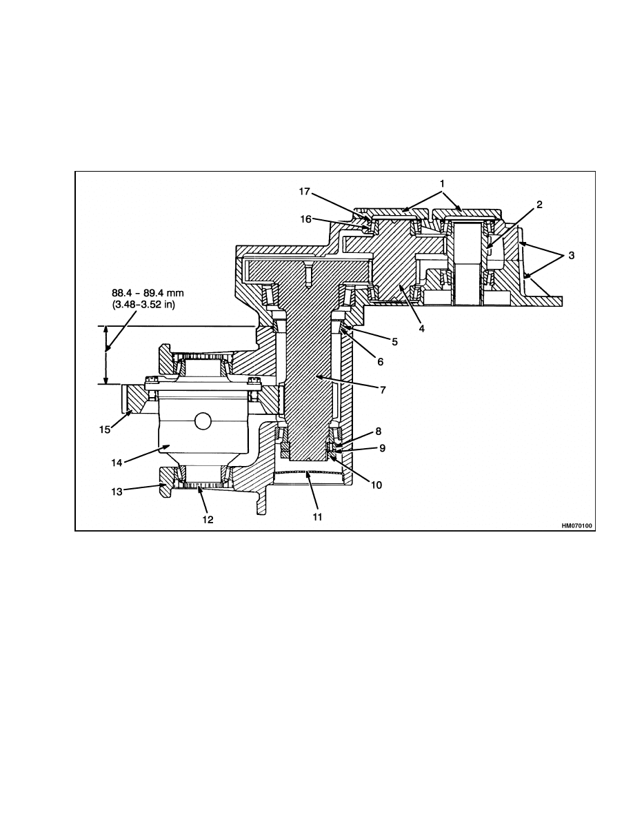
16. Adjust and install the bearing cap for the pinion
using the procedures described in Step 15.
1.
BEARING CAP
2.
PINION
3.
SPEED REDUCER HOUSING
4.
CLUSTER GEAR
5.
O-RING
6.
BEARING CUP (ALIGNMENT)
7.
REDUCTION GEAR
8.
BEARING LOCK NUT
9.
LOCK RING
10. LOCK NUT
11. EXPANSION PLUG
12. ADJUSTMENT NUT
13. DIFFERENTIAL BEARING CAP
14. DIFFERENTIAL
15. DRIVE GEAR
16. BEARING CUP
17. SHIMS
Figure 13. Speed Reducer and Differential
17. Apply a bead of sealant (Loctite 515 or equiva-
lent) to the flange of the axle housing. Install
the differential housing onto the axle housing.
Tighten the bolts and capscrews that fasten the
two housings together to 38 N•m (28 lbf ft).
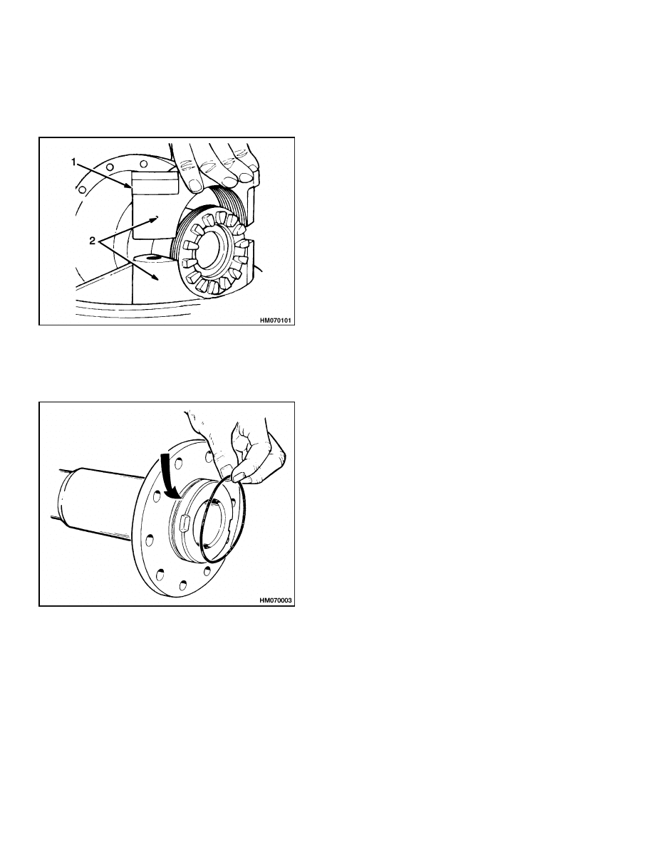
18. If removed, install the axle spindles on the axle
housing, Install new O-rings on the axle spindles.
See Figure 15. Install the axle spindle into the
axle housing. Tighten the capscrews to 90 N•m
(66 lbf ft). Lubricate the axle spindles with Never
Seez
®
and slide the mounts on the axle spindles.
19. Install the capscrew, washer, isolators, and
spacer between the right-hand axle mount
and the speed reducer housing. See Figure 6.
Tighten the capscrew to 165 N•m (122 lbf ft).
9
Drive Axle, Speed Reducer, and Differential Repair
1400 SRM 575
20. Install a new O-ring on the flange of the motor.
Use a sling to lift the traction motor. Align the
traction motor with the pinion in the speed re-
ducer.
1.
BEARING CAP
2.
ALIGNMENT MARKS
Figure 14. Bearing Caps Installation
Figure 15. New O-Rings Installation
21. Align the holes in the speed reducer and the mo-
tor housing. Install the capscrews that hold the
traction motor to the speed reducer. Tighten the
capscrews to 38 N•m (28 lbf ft).
22. Install the bolt and nuts at the support on the
bottom of the speed reducer housing. Adjust the
bolt until it touches the motor housing. Turn the
bolt an additional 1/2 turn counterclockwise to
push on the traction motor. Tighten the upper
nut. Tighten the lower nut to 33 N•m (24 lbf ft)
without moving the bolt.
INSTALL
1.
Use a floor jack to slide the drive unit assembly
in position under the lift truck.
2.
Align the bolt holes in the axle mounts and the
frame. Lubricate the alignment pins with Never-
Seez and install them. The alignment pins can
be a tight fit. See the procedures in Figure 4 and
Figure 5. Install the bolts that fasten the axle
mounts to the frame. Tighten the nuts and bolts
as follows:
a. If the torque wrench is on the head of the bolt,
tighten the bolt to 780 N•m (575 lbf ft).
b. If the torque wrench is on the nut, tighten
the nut to 715 N•m (528 lbf ft).
3.
Assemble the brake assembly to the axle mount
as described in the section Brake System 1800
SRM 566.
NOTE: The outer wheel bearing is lubricated by gear
oil from the differential housing. The inner wheel
bearing is lubricated by wheel bearing grease. Do
not use too much grease to lubricate the inner wheel
bearing so that grease is pushed past the seal into
the area for the brakes.
4.
Install a new oil seal in each hub. Install the oil
seal with the lip toward the outer bearing. Install
the inner bearing and seal. Put wheel bearing
grease on the inner bearing.
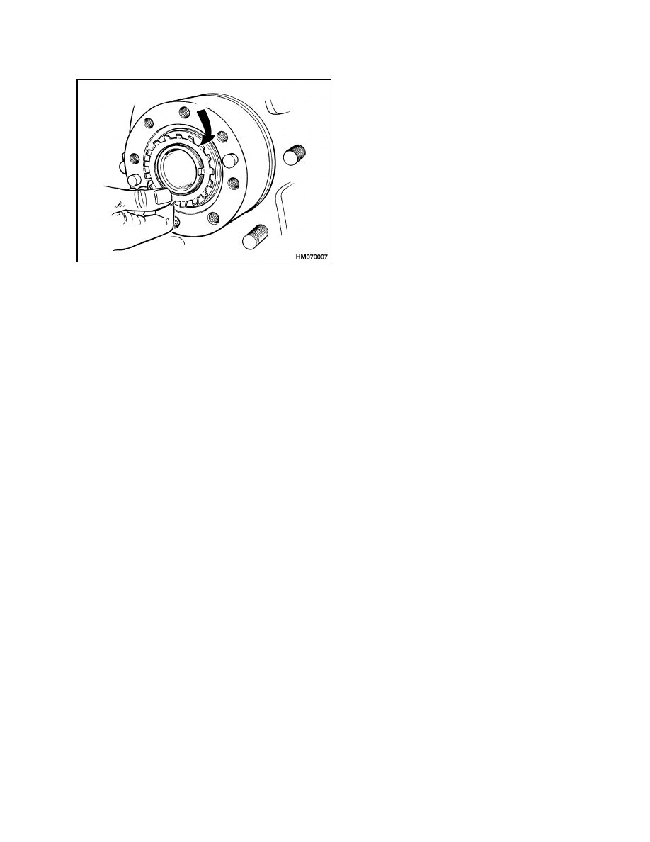
5.
Install hub on the axle spindle. Be careful that
the seals are not damaged during installation.
Install the outer bearing, lock plate, and lock
nut. Tighten the lock nut to 205 N•m (151 lbf ft)
while rotating the hub. Loosen the lock nut un-
til the hub turns freely. The torque must be less
than 27 N•m (20 lbf ft). Tighten the lock nut
to 34 N•m (25 lbf ft) or until the first alignment
position after 34 N•m (25 lbf ft). Bend the lock
plate over the lock nut. See Figure 16.
10
1400 SRM 575
Torque Specifications
Figure 16. Lock Plate Installation
6.
Apply a bead of sealant (Loctite 515 or equiv-
alent) on the flange of the axle shaft.
Install
the axle shafts and capscrews. Tighten the cap-
screws to 98 N•m (72 lbf ft).
7.
Connect the brake lines to the wheel cylinders.
Make sure there is brake fluid in the reservoir.
Remove air from the brake system.
8.
Adjust the clearance of the brake shoes as de-
scribed in the section Brake System 1800 SRM
566.
9.
Install the wheels and tires. Tighten the wheel
nuts to 237 to 305 N•m (175 to 225 lbf ft).
10. Install and tighten the drain plug. Fill the differ-
ential housing with SAE 90 EP gear oil through
the fill hole until the oil level is even with the bot-
tom of the fill hole. Install the plug.
11. Install the mast as described in the section Mast,
Repairs 4000 SRM 522. Install the battery as
described in the section Periodic Maintenance
8000 SRM 1060. Remove the blocks so the lift
truck is on its tires.
Torque Specifications
Axle Mounts to Frame
Torque Wrench on Head of Bolt 780 N•m
(575 lbf ft)
Torque Wrench on Nut of Bolt 715 N•m (527 lbf ft)
Axle Housing to Differential Housing
38 N•m (28 lbf ft)
Axle Shaft Capscrews
98 N•m (72 lbf ft)
Back Plate to Axle Mount Capscrews
5/8 in. Capscrews 245 N•m (180 lbf ft)
1/2 in. Capscrews 125 N•m (92 lbf ft)
Bearing Cap Capscrews for Differ-
ential Bearings
95 to 110 N•m (70 to 81 lbf ft)
Bearing Cap Capscrews for Speed Reducer
19 N•m (14 lbf ft)
Differential Case Halves
50 N•m (37 lbf ft)
Drive Gear to Differential Case
111 N•m (82 lbf ft)
Retainer Capscrews for Adjustment Nuts
19 N•m (14 lbf ft)
Speed Reducer Housing to Differen-
tial Housing
52 N•m (38 lbf ft)
Traction Motor to Speed Reducer Housing
38 N•m (28 lbf ft)
Wheel Cylinder Capscrews
7/16 in. Capscrews 78 to 91 N•m (58 to 67 lbf ft)
1/2 in. Capscrews 91 to 102 N•m (67 to 75 lbf ft)
Wheel Nuts
237 to 305 N•m (175 to 225 lbf ft)
11

Troubleshooting
1400 SRM 575
Troubleshooting
PROBLEM
POSSIBLE CAUSE
PROCEDURE OR ACTION
The lift truck will not move.
An axle shaft is broken.
Install new axle shaft.
The differential is damaged.
Repair differential.
Pinion is damaged.
Install a new pinion.
Cluster gear or reduction gear is
damaged.
Install new gear(s).
The drive axle has leaks.
The drain or fill plug has damaged
threads, is loose, or is missing.
Repair threads. Tighten plug. Install
missing part.
The O-rings or seals have damage.
Install new O-rings and seals.
The drive axle housing is cracked.
Install new drive axle housing.
Speed reducer housing is cracked.
Install a new housing.
The drive axle makes noise.
The bearings have damage.
Install new parts.
The brake assembly is damaged.
Repair brake assembly.
The oil level is low.
Fill as required. Check for leaks.
The axle mounting capscrews are
loose.
Tighten
capscrews
to
specified
torque.
Speed reducer gears are damaged.
Install new gears.
12


TECHNICAL PUBLICATIONS
1400 SRM 575
4/05 (3/03)(5/95) Printed in United Kingdom
Document Outline
Wyszukiwarka
Podobne podstrony:
897653 1800SRM0566 (04 2005) UK EN
1565582 1600SRM1114 (04 2005) UK EN
897345 1400SRM0413 (03 2005) UK EN
1574068 1400SRM1171 (08 2005) UK EN
897097 1600SRM0316 (04 2005) UK EN
1463744 2200SRM0739 (04 2005) UK EN
897653 1800SRM0566 (04 2005) UK EN
1510478 8000SRM0988 (06 2005) UK EN
1568204 0700SRM1159 (08 2005) UK EN
1566043 0620SRM1115 (08 2005) UK EN
1459370 1600SRM0720 (07 2005) UK EN
więcej podobnych podstron