STEERING HOUSING
AND CONTROL UNIT
H2.00-3.20XM (H40-65XM) [H177];
S1.50-1.75XM, S2.00XMS (S25-40XM) [D010];
E1.50-1.75XM, E2.00XMS (E25-40XM
2
S) [D114];
H1.50-1.75XM, H2.00XMS (H25-35XM, H40XMS) [E001];
J2.00-3.20XM (J40-60XM
2
) [A216];
E2.00-3.20XM (E45-65XM
2
) [F108];
J2.00-3.20XM (J40-65Z) [A416];
E1.50-2.00XM (E25-35Z, E40ZS) [E114]; N30XMH,
N30XMH
2
[C210]; V30ZMD [D210];
E2.00-3.20XM (E45-65Z) [G108]; E3.50-5.50XL, E4.50XLS
(E70-120Z, E100ZS) [D098]
PART NO. 1459370
1600 SRM 720

SAFETY PRECAUTIONS
MAINTENANCE AND REPAIR
• When lifting parts or assemblies, make sure all slings, chains, or cables are correctly
fastened, and that the load being lifted is balanced. Make sure the crane, cables, and
chains have the capacity to support the weight of the load.
• Do not lift heavy parts by hand, use a lifting mechanism.
• Wear safety glasses.
• DISCONNECT THE BATTERY CONNECTOR before doing any maintenance or repair
on electric lift trucks. Disconnect the battery ground cable on internal combustion lift
trucks.
• Always use correct blocks to prevent the unit from rolling or falling. See HOW TO PUT
THE LIFT TRUCK ON BLOCKS in the Operating Manual or the Periodic Mainte-
nance section.
• Keep the unit clean and the working area clean and orderly.
• Use the correct tools for the job.
• Keep the tools clean and in good condition.
• Always use HYSTER APPROVED parts when making repairs. Replacement parts
must meet or exceed the specifications of the original equipment manufacturer.
• Make sure all nuts, bolts, snap rings, and other fastening devices are removed before
using force to remove parts.
• Always fasten a DO NOT OPERATE tag to the controls of the unit when making repairs,
or if the unit needs repairs.
• Be sure to follow the WARNING and CAUTION notes in the instructions.
• Gasoline, Liquid Petroleum Gas (LPG), Compressed Natural Gas (CNG), and Diesel fuel
are flammable. Be sure to follow the necessary safety precautions when handling these
fuels and when working on these fuel systems.
• Batteries generate flammable gas when they are being charged. Keep fire and sparks
away from the area. Make sure the area is well ventilated.
NOTE: The following symbols and words indicate safety information in this
manual:
WARNING
Indicates a condition that can cause immediate death or injury!
CAUTION
Indicates a condition that can cause property damage!

Steering Housing and Control Unit
Table of Contents
TABLE OF CONTENTS
General ...............................................................................................................................................................
Description .........................................................................................................................................................
Operation............................................................................................................................................................
Steering Wheel and Column Assembly Repair ................................................................................................
Assembly Components, Remove ...................................................................................................................
Steering Control Unit, Disassemble .............................................................................................................
Steering Control Unit, Clean ........................................................................................................................
Steering Control Unit, Assemble ..................................................................................................................
Assembly Components, Install .....................................................................................................................
System Air Removal ..........................................................................................................................................
Troubleshooting..................................................................................................................................................
This section is for the following models:
H2.00-3.20XM (H40-65XM) [H177];
S1.50-1.75XM, S2.00XMS (S25-40XM) [D010];
E1.50-1.75XM, E2.00XMS (E25-40XM
2
S) [D114];
H1.50-1.75XM, H2.00XMS (H25-35XM, H40XMS) [E001];
J2.00-3.20XM (J40-60XM
2
) [A216];
E2.00-3.20XM (E45-65XM
2
) [F108];
J2.00-3.20XM (J40-65Z) [A416];
E1.50-2.00XM (E25-35Z, E40ZS) [E114];
N30XMH, N30XMH
2
[C210];
V30ZMD [D210];
E2.00-3.20XM (E45-65Z) [G108];
E3.50-5.50XL, E4.50XLS (E70-120Z, E100ZS) [D098]
©2005 HYSTER COMPANY
i

"THE
QUALITY
KEEPERS"
HYSTER
APPROVED
PARTS
1600 SRM 720
Description
General
This section has the description and repair procedures for the steering housing and the steering control unit.
Additional information on parts of the steering system can be found in the Steering Axle and Hydraulic
System service manual sections for your lift truck.
Description
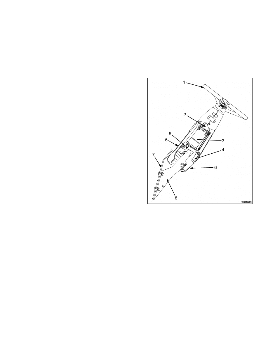
The steering column assembly uses a steering con-
trol unit with hose connections on the bottom of the
unit. The steering housing has mounts for the steer-
ing column and the steering control unit. The steer-
ing wheel is installed on the steering column. See
Figure 1. The housing is adjustable and is held in po-
sition by a latch. The position of the housing can be
changed for operator comfort. The steering housing
is also the mount for control levers and some instru-
ment clusters.
The steering system is a hydraulic system that does
not have a mechanical connection between the steer-
ing wheel and the steering axle. The control of the
steering is through a hydraulic circuit.
If the hydraulic pump for the steering system does
not operate, steering is still possible. A check valve
permits the steering control unit to control the steer-
ing cylinder. The lift truck is difficult to steer when
the steering pump is not operating, but the steer-
ing control unit can operate the steering cylinder and
make steering possible.
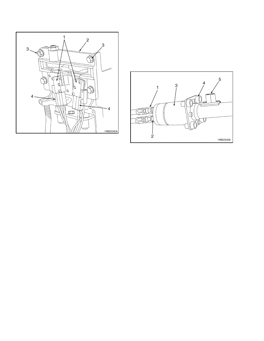
NOTE:
INSTRUMENT CLUSTER NOT SHOWN.
H2.00-3.20XM (H40-65XM) SHOWN.
1.
STEERING WHEEL
2.
STEERING
COLUMN
3.
STEERING
CONTROL UNIT
4.
COLUMN TILT
LEVER
5.
LATCH
6.
COVER
7.
COWL
8.
MOUNT
Figure 1. Steering Housing Assembly
1
Operation
1600 SRM 720
Operation
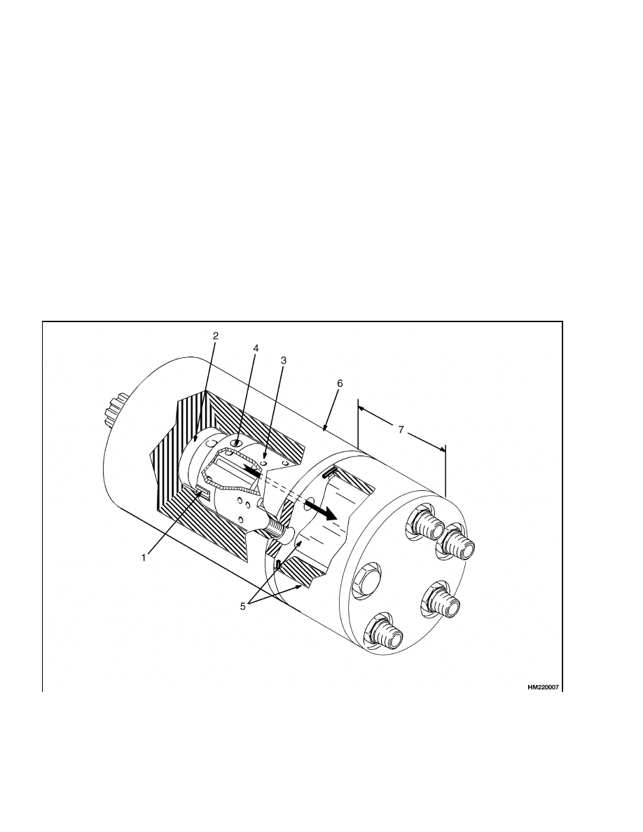
The steering control unit is a rotary valve operated by
the steering wheel. See Figure 2. During the steer-
ing operation, the steering control unit controls the
direction and amount of oil flow to the steering cylin-
der. The steering cylinder in the axle actuates the
steering linkage to move the steer tires. Hydraulic
oil returns from the steering cylinder to the steering
control unit and then to the hydraulic tank.
Turning the steering wheel actuates three main
parts of the steering control unit: the spool for the
control section, the sleeve for the control section, and
the rotor in the metering section. When the steering
wheel is not moving, the spool and sleeve are held
in the NEUTRAL (center) position by springs. Dur-
ing this time, oil flows freely through the steering
control unit but none flows to the steering cylinder.
As the steering wheel is turned, the spool just be-
gins to rotate. The springs try to move the sleeve to
keep the NEUTRAL position between the spool and
sleeve. However, the necessary force to turn the ro-
tor is greater than the pressure of the springs. The
springs begin to bend, letting the spool move a small
amount within the sleeve. The spool stops moving
when it touches the center pin. In this position, the
holes in the sleeve and the spool are aligned. Oil com-
ing into the control unit flows to the metering section.
More rotation of the steering wheel causes the spool
to rotate the pin. This action causes the rotation of
the sleeve and the rotor in the metering section. The
oil then flows to one side of the steering cylinder. Oil
from the other side of the cylinder returns through
the control section of the steering control unit.
1.
SPRING SET
2.
SPOOL
3.
SLEEVE
4.
CENTER PIN
5.
GEAR SET
6.
CONTROL SECTION
7.
METERING SECTION
Figure 2. Steering Control Unit
2
1600 SRM 720
Steering Wheel and Column Assembly Repair
When the steering wheel stops moving, the meter-
ing action in the metering section also stops. The
NEUTRAL position springs return the sleeve to the
NEUTRAL position, stopping oil flow to or from the
cylinder. The pressure stays in the steering cylinder
to keep the steer tires in position. Oil from the pump
flows through the steering control unit to the tank or
other parts of the system. To return the steer wheels
to the straight position, the steering wheel must be
rotated in the opposite direction. The steering con-
trol unit will operate as described, but all parts will
rotate in the opposite direction.
Steering Wheel and Column Assembly Repair
The upper end of the steering shaft has splines for the
steering wheel. A large hex nut holds the steering
wheel onto the steering column. The horn button is
the cover for the center of the steering wheel. The
lower end of the steering column has splines or a tang
to engage the steering control unit. See Figure 5 and
Figure 6.
The steering column assembly is adjustable and held
in position by a latch. The position of the steering col-
umn assembly can be changed as needed for different
operator requirements. An access cover on the steer-
ing column gives access to the steering control unit,
key switch, horn switch, and if installed, the direc-
tion switch.
ASSEMBLY COMPONENTS, REMOVE
NOTE: This procedure is for the removal of all com-
ponents of the steering column assembly. All compo-
nents are not often removed for a repair procedure.
Do only those steps of the procedure necessary to re-
move the required component. See Figure 5 and Fig-
ure 6.
WARNING
The hydraulic hoses must be connected to the
correct ports or the steering system will not op-
erate as expected, which can cause damage or
personal injury. Make sure the hoses are iden-
tified and connected correctly.
CAUTION
Disconnect the negative battery cable on inter-
nal combustion trucks. Disconnect the battery
connector on electric trucks. Disconnect the
battery before removing any covers.
1.
Attach a tag on the battery connector or negative
cable stating DO NOT CONNECT BATTERY.
Move the steering column to the most FOR-
WARD position. Remove the column tilt lever.
Remove the upper and lower access covers from
the steering column.
2.
Remove the key switch and static strap from the
housing of the steering column. Make an identi-
fication of the electric wires and disconnect them
from the key switch.
3.
On units with the Direction Control Handle,
Remove the direction switch assembly from the
housing of the steering column. Make an identi-
fication of the electric wires and disconnect them
from the direction switch. See Figure 3.
4.
Remove the plastic rivets that fasten the bracket
for the horn switch to the housing of the steering
column. Move the horn switch and bracket away
from the steering column. See Figure 5 and Fig-
ure 6.
CAUTION
If a puller tool is used to remove steering wheel
from steering column, be careful not to damage
the horn wires.
5.
Remove the horn button assembly and electrical
wires. Remove the large hex nut and the steer-
ing wheel from the shaft. A puller tool makes
removal of the steering wheel easier, but not all
steering wheels have puller holes.
6.
On
lift
truck
models
J2.00-3.20XM
(J40-
60XM
2
)
(A216),
E1.50-1.75XM,
E2.00XMS
(E25-40XM
2
S) (D114),
N30XMH, N30XMH2
(C210), and E2.00-3.20XM (E45-65XM
2
) (F108)
units, remove the optical encoder housing and
optical encoder from the steering column. Make
an identification of the electrical wires and dis-
connect them from the assemblies. See Figure 5.
3
Steering Wheel and Column Assembly Repair
1600 SRM 720
NOTE:
DIRECTION
CONTROL
HANDLE
AS-
SEMBLY FOR MODELS J2.00-3.20XM [J40-65Z]
(A416),
E1.50-2.00XM [E25-35Z, E40ZS] (E114),
N30XMH, AND N30XMH
2
(C210), V30ZMD (D210),
E3.50-5.50XL, E4.50XLS (E70-120Z, E100ZS) (D098),
AND E2.00-3.20XM [E45-65Z] (G108) IS SHOWN.
OTHER TRUCK DIRECTION CONTROL HANDLE
ASSEMBLIES ARE SIMILAR.
1.
DIRECTION
SWITCHES
2.
SHIFT LEVER
ASSEMBLY
3.
SCREW
4.
ELECTRICAL
CONNECTORS
Figure 3. Direction Control Handle Assembly
7.
On lift truck models J2.00-3.20XM [J40-65Z]
(A416), E1.50-2.00XM [E25-35Z, E40ZS] (E114),
V30ZMD
(D210),
E3.50-5.50XL,
E4.50XLS
(E70-120Z, E100ZS) (D098), and E2.00-3.20XM
[E45-65Z] (G108), disconnect the connector. Re-
move the two capscrews and steering sensor
from the steering column. See Figure 6.
8.
Make an identification of the hydraulic hoses
at the steering control unit so they can be con-
nected correctly during assembly. See Figure 4,
Figure 5, Figure 6, and the WARNING in the
beginning of this section. Some hydraulic hoses
have fittings that will permit disconnection at
the steering control unit. Disconnect the other
hydraulic hoses at the base of the cowl, the
control valve, or the steering pump.
Remove
all mount clamps so that the hoses will turn
freely and not become twisted. Disconnect the
hydraulic hoses at the bottom of the steering
control unit. Install plugs at all hoses and ports
to prevent dirt from entering the steering hy-
draulic system.
1.
HYDRAULIC HOSE ENDS
2.
HOSE PORTS
3.
STEERING CONTROL UNIT
4.
SCREWS
5.
HORN SWITCH
Figure 4. Hydraulic Hose Connections
9.
If your model of lift truck has an instrument
cluster that wraps around the steering col-
umn, remove the instrument cluster.
The
removal procedures for the instrument clus-
ter can be found in the service manual sec-
tions Instrument Cluster 2200 SRM 514 for
models
H2.00-3.20XM
(H40-65XM)
(H177),
S1.50-1.75XM, S2.00XMS (S25-40XM) (D010)
and
H1.50-1.75XM,
H2.00XMS
(H25-35XM,
H40XMS)
(E001),
or
Electrical
System,
Replacement,
Checks,
and Adjustments
Trucks with EV-100/200ZX or SR (SEM)
and
SP
Motor
Controllers
2200
SRM
560 for models E1.50-1.75XM (E25-35XM
2
)
(D114), E2.00XMS (E40XM
2
S), E2.00-3.20XM
(E45-65XM
2
)
(F108),
and
J2.00-3.20XM
(J40-60XM
2
) (A216).
10. If there is a instrument cluster on the steering
column housing, disconnect all plugs connected
to the display panel.
4
1600 SRM 720
Steering Wheel and Column Assembly Repair
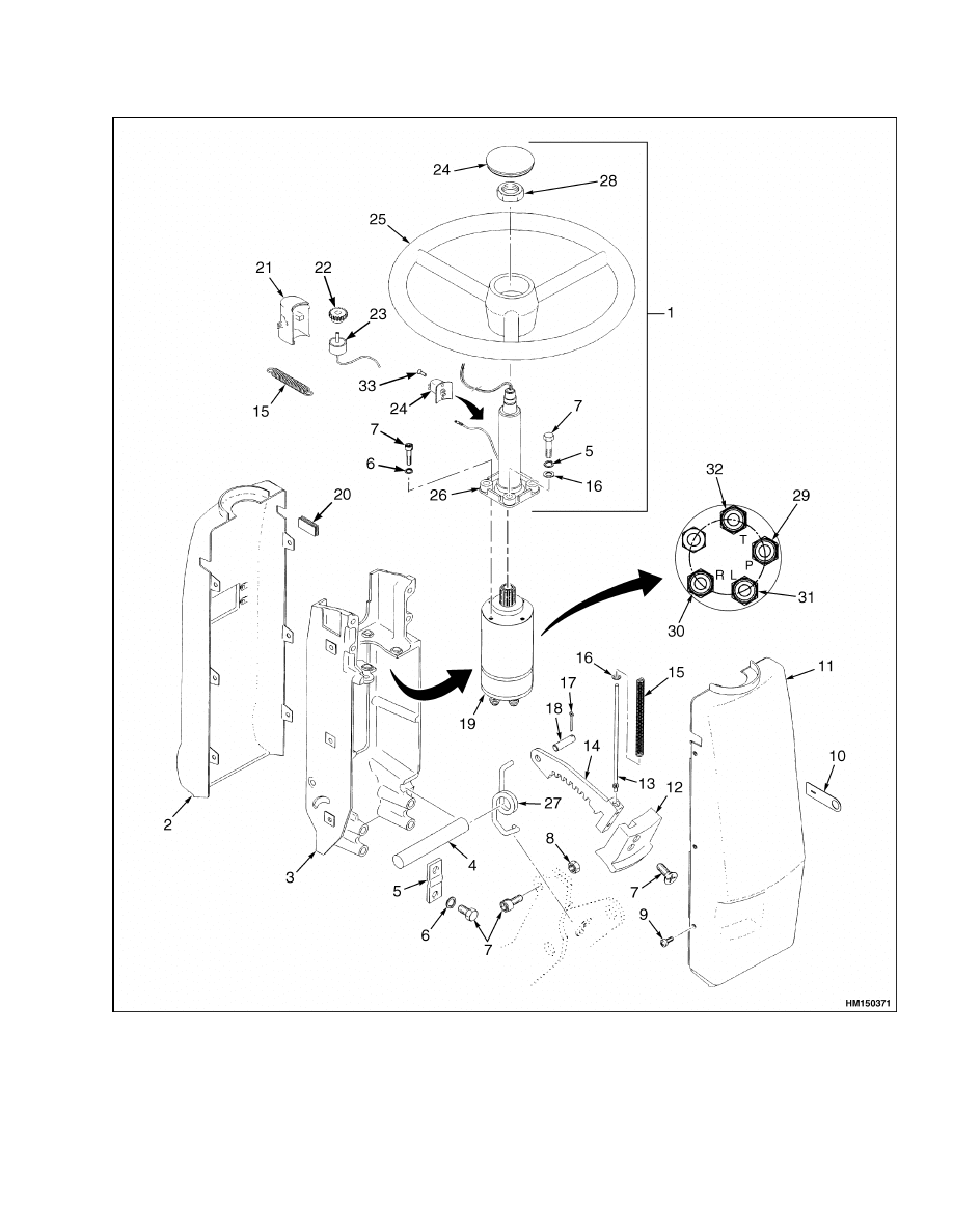
Figure 5. Steering Column Assembly, For Models J2.00-3.20XM (J40-60XM
2
) (A216), E1.50-1.75XM,
E2.00XMS (E25-40XM
2
S,(D114), N30XMH, N30XMH
2
(C210), and E2.00-3.20XM (E45-65XM
2
) (F108)
5

Steering Wheel and Column Assembly Repair
1600 SRM 720
Legend for Figure 5
NOTE: * NOT INCLUDED ON LIFT TRUCK MODELS H2.00-3.20XM (H40-65XM) (H177), S1.50-1.75XM,
S2.00XMS (S25-40XM) (D010), AND H1.50-1.75XM, H2.00XMS (H25-35XM, H40XMS (E001)
1.
ON-DEMAND STEERING COMPONENTS
2.
UPPER ACCESS COVER
3.
BRACKET
4.
PIVOT (STEERING) SHAFT
5.
PLATE
6.
LOCKWASHER
7.
CAPSCREW
8.
LOCK NUT
9.
SCREW
10. STATIC GROUND PATCH
11. LOWER ACCESS COVER
12. COLUMN TILT LEVER
13. PUSH ROD
14. LATCH
15. SPRING
16. WASHER
17. COTTER PIN
18. PIN
19. STEERING CONTROL UNIT
20. PLUG (WITHOUT TURN SIGNAL)
21. OPTICAL ENCODER HOUSING*
22. GEAR*
23. OPTICAL ENCODER*
24. HORN BUTTON ASSEMBLY
25. STEERING WHEEL
26. STEERING COLUMN
27. RETURN SPRING
28. LARGE HEX NUT
29. INPUT
30. RIGHT TURN
31. LEFT TURN
32. RETURN
33. PLASTIC RIVET
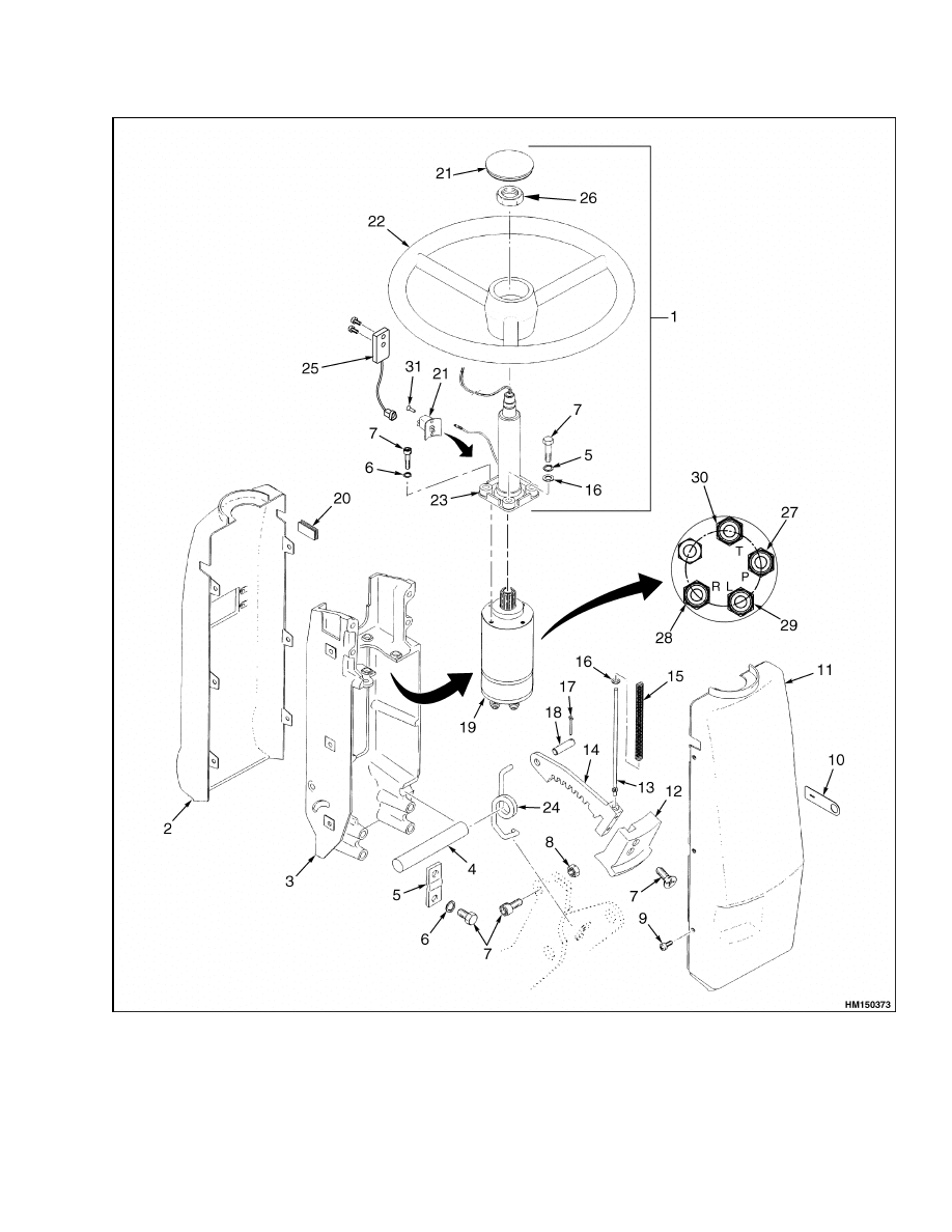
Legend for Figure 6
1.
ON-DEMAND STEERING COMPONENTS
2.
UPPER ACCESS COVER
3.
BRACKET
4.
PIVOT (STEERING) SHAFT
5.
PLATE
6.
LOCKWASHER
7.
CAPSCREW
8.
LOCK NUT
9.
SCREW
10. STATIC GROUND PATCH
11. LOWER ACCESS COVER
12. COLUMN TILT LEVER
13. PUSH ROD
14. LATCH
15. SPRING
16. WASHER
17. COTTER PIN
18. PIN
19. STEERING CONTROL UNIT
20. PLUG (WITHOUT TURN SIGNAL
21. HORN BUTTON ASSEMBLY
22. STEERING WHEEL
23. STEERING COLUMN
24. RETURN SPRING
25. STEERING SENSOR
26. LARGE HEX NUT
27. INPUT
28. RIGHT TURN
29. LEFT TURN
30. RETURN
31. PLASTIC RIVET
6
1600 SRM 720
Steering Wheel and Column Assembly Repair
Figure 6. Steering Column Assembly, Models J2.00-3.20XM [J40-65Z] (A416), E1.50-2.00XM [E25-35Z,
E40ZS] (E114), V30ZMD (D210), E2.00-3.20XM [E45-65Z] (G108), and E3.50-5.50XL, E4.50XLS
(E70-120Z, E100ZS) (D098)
7
Steering Wheel and Column Assembly Repair
1600 SRM 720
11. Remove the tilt stop screw located at the bottom
left side of the steering column bracket.
12. Remove the capscrews, lockwashers, and lock
plates that fasten the steering column to the
pivots on the lift truck. Remove the steering col-
umn from the lift truck. Make sure the electric
wires and the hydraulic hoses are not damaged
as the steering column is removed.
13. Remove the four capscrews that hold the steer-
ing column to the bracket. Remove the four cap-
screws or nuts that fasten the steering control
unit to the steering column.
STEERING CONTROL UNIT,
DISASSEMBLE
1.
Place the steering pump into a soft jaw vise with
the splined shaft facing down.
2.
Remove the hydraulic fittings and the special
screws, and rotate the steering pump 90 degrees
sideways in the vise. Discard the O-rings. See
Figure 7.
3.
Remove the end cover, spacer, gear housing,
and gear from the steering pump. Discard the
O-rings.
4.
Remove the cardan shaft from the spool assem-
bly.
5.
Remove the check ball, ball stop, and emergency
steering ball from the pump housing.
6.
Remove the spool assembly from the pump hous-
ing.
NOTE: To help with installation of the thrust bearing
assembly, note the positions of the thrust washers
on either side of the thrust bearing while performing
Step 7.
7.
Remove the thrust bearing assembly from the
shaft end of the spool assembly.
8.
Remove the retaining ring from the spool assem-
bly.
9.
Press the cross pin out of the spool assembly.
10. Press the spool from the sleeve and remove the
springs from the spool. Press the spool from the
sleeve and remove the springs from the spool.
11. Remove the shaft seals from the pump housing.
Discard the seals.
STEERING CONTROL UNIT, CLEAN
WARNING
Cleaning solvents can be flammable and toxic
and can cause skin irritation.
When using
cleaning solvents, always follow the solvent
manufacturer’s recommended safety precau-
tions.
WARNING
Compressed air can move particles so that they
cause injury to the user or to other personnel.
Make sure that the path of the compressed air
is away from all personnel.
Wear protective
goggles or a face shield to prevent injury to the
eyes.
Clean all the parts in solvent. Dry the parts with
compressed air. Do not dry the parts with a cloth.
Make sure all surfaces are free of scratches and sharp
edges.
STEERING CONTROL UNIT, ASSEMBLE
1.
Using a seal installer, install the shaft seals in
the pump housing.
2.
Install the spool into the sleeve with the key slots
opposite each other.
3.
Insert the curved springs between the flat
springs. See Figure 7. Install the spring set into
the spool assembly.
NOTE: The retaining ring must be able to rotate
unimpeded by the springs.
4.
Center the springs in the spool assembly, and in-
stall the retaining ring over the sleeve.
5.
Install the cross pin into the spool assembly.
6.
Install the thrust bearing assembly, as noted dur-
ing removal, on the spool assembly.
7.
Place the pump housing in a soft-jawed vise in
the horizontal position. Install the spool assem-
bly into the housing while holding the cross pin
in a horizontal position.
8
1600 SRM 720
Steering Wheel and Column Assembly Repair
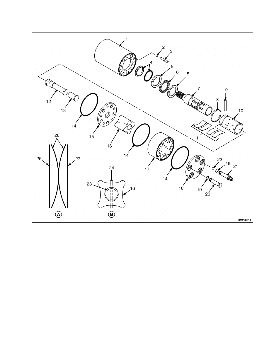
A. ORIENTATION OF NEUTRAL SPRINGS
B. ORIENTATION OF GEAR WHEEL
1.
PUMP HOUSING
2.
EMERGENCY STEERING BALL
3.
BALL STOP
4.
SHAFT SEAL
5.
THRUST WASHER
6.
THRUST BEARING
7.
SPOOL
8.
RETAINING RING
9.
CROSS PIN
10. SLEEVE
11. SPRING SET
12. CARDAN SHAFT
13. SPACER
14. O-RING
15. DISTRIBUTOR PLATE
16. GEAR
17. GEAR HOUSING
18. END COVER
19. O-RING
20. SCREW
21. SPECIAL SCREW (HYDRAULIC FITTING)
22. CHECK BALL
23. CARDAN SHAFT GEAR TEETH
24. SPOOL ASSEMBLY PIN
25. FLAT SPRING
26. CURVED SPRING
27. FLAT SPRING
Figure 7. Steering Pump
9
Steering Wheel and Column Assembly Repair
1600 SRM 720
8.
Rotate the pump housing to the vertical position,
and rotate the spool so that the pin in the spool
is pointing to the "P" port position. See Figure 5
and Figure 6.
9.
Install the emergency steering ball, ball stop,
and check ball in the "P" port. See Figure 5 and
Figure 6.
10. Install a new O-ring on the housing and place the
distributor plate on the housing, with the holes
properly aligned with the pump housing.
11. Install the cardan shaft and rotate it until it is
engaged with the pin in the spool assembly, and
until the teeth of the gear end are aligned as
shown in Figure 7.
12. Install the gear wheel onto the cardan shaft as
shown in Figure 7.
13. Install new O-rings onto the gear housing and in-
stall the gear housing onto the distributor plate,
making sure that the holes are properly aligned.
14. Place the spacer over the cardan shaft, and in-
stall the end cover with the "P" hole lined up with
the "P" port in the housing.
15. Install new O-rings, hydraulic fittings, and spe-
cial screws. Tighten the fittings and the special
screws to 30 ±3 N•m (266 ±27 lbf in) in a cross
pattern.
ASSEMBLY COMPONENTS, INSTALL
NOTE: This procedure is for the installation of all
components of the steering column assembly.
All
components are not often installed for a repair proce-
dure. Do only those steps of the procedure necessary
to install the required component. See Figure 5 and
Figure 6.
WARNING
The hydraulic hoses must be connected to the
correct ports or the steering system will not op-
erate as expected, which can cause damage or
personal injury. Make sure the hoses are iden-
tified and connected correctly.
1.
Using four capscrews, attach the steering control
unit assembly to the steering column. Install the
steering column and steering control unit assem-
bly on the bracket Install the four capscrews that
mount the steering column to the bracket. See
Figure 5 and Figure 6.
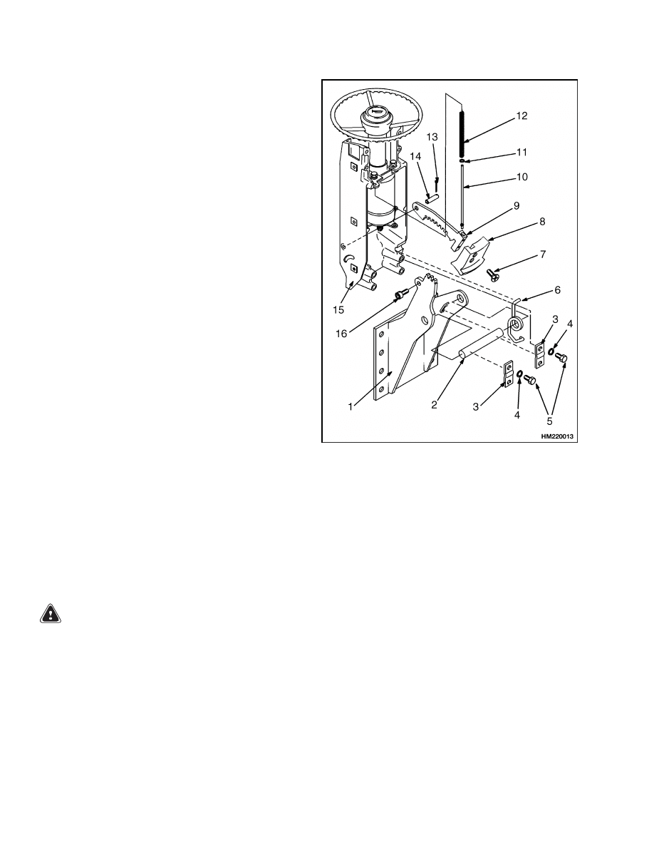
1.
MOUNT
2.
PIVOT (STEERING)
SHAFT
3.
PLATE
4.
LOCKWASHER
5.
CAPSCREW
6.
RETURN SPRING
7.
SCREW
8.
COLUMN TILT
LEVER
9.
LATCH
10. PUSH ROD
11. WASHER
12. SPRING
13. COTTER PIN
14. PIN
15. BRACKET
16. SOCKET HEAD
SCREW
Figure 8. Install Steering Components
2.
If a instrument cluster was removed from the
steering column housing, install it by connecting
all plugs.
3.
If an instrument cluster was removed, In-
stall the instrument cluster on the front cover.
for the installation procedures, see the ser-
vice manual sections Instrument Cluster
2200 SRM 514 for models H2.00-3.20XM (H40-
65XM), S1.50-1.75XM, S2.00XMS (S25-40XM)
and
H1.50-1.75XM,
H2.00XMS
(H25-35XM,
H40XMS), or Electrical System, Replace-
ment, Checks, and Adjustments Trucks
with EV-100/200ZX or SR (SEM) and SP
10
1600 SRM 720
Steering Wheel and Column Assembly Repair
Motor Controllers 2200 SRM 560 for mod-
els
E1.50-1.75XM
(E25-35XM
2
),
E2.00XMS
(E40XM
2
S), E2.00-3.20XM (E45-65XM
2
), and
J2.00-3.20XM (J40-60XM
2
).
WARNING
The hydraulic hoses MUST be connected to
the correct ports and fittings or the steering
system will not operate as expected.
This
unexpected operation can cause damage or
personal injury. Make sure the hoses are iden-
tified and connected correctly.
4.
Connect the hydraulic hoses to the steering con-
trol unit, the cowl, the control valve, or the steer-
ing pump as removed during removal. Make sure
each hydraulic hose is connected to the correct
ports or fittings as identified during removal. See
Figure 4.
5.
On lift trucks models J2.00-3.20XM (J40-
60XM
2
)
(A216),
E1.50-1.75XM,
E2.00XMS
(E25-40XM
2
S) (D114),
N30XMH, N30XMH
2
(C210), and E2.00-3.20XM (E45-65XM
2
) (F108)
install the optical encoder components by con-
necting the electrical wires to the optical encoder.
Install the optical encoder and optical encoder
housing to the steering column. See Figure 5.
6.
On lift truck models J2.00-3.20XM [J40-65Z]
(A416), E1.50-2.00XM [E25-35Z, E40ZS] (E114),
V30ZMD
(D210),
E2.00-3.20XM
[E45-65Z]
(G108), and E3.50-5.50XL, E4.50XLS (E70-120Z,
E100ZS) (D098) models, connect the connector
and using two capscrews, install the steering
sensor on the steering column. See Figure 6.
7.
Install the steering wheel and large hex nut.
Tighten the large hex nut to 40 to 54 N•m (30 to
40 lbf ft). Connect the wire at the horn button
and install the horn button.
8.
If removed, install the static strap and wires on
the key switch that were identified during re-
moval. Install the key switch.
9.
If removed, install the wires on the direction
switch that were identified during removal.
Install the direction switch in the housing and
install the two capscrews. See Figure 3.
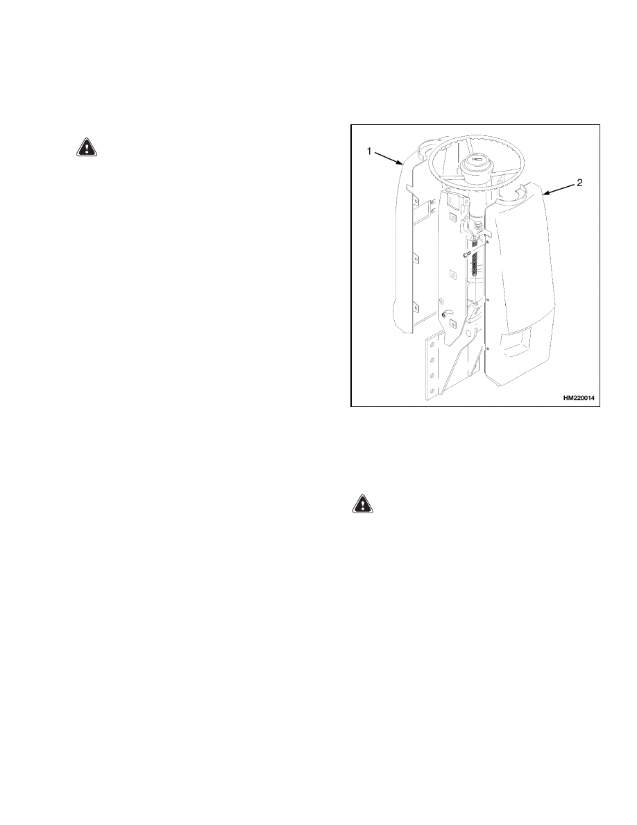
10. Connect the wire connectors at the bottom of the
steering column. Install the upper and lower ac-
cess covers on the steering column. See Figure 9.
1.
UPPER ACCESS
COVER
2.
LOWER ACCESS
COVER
Figure 9. Install Steering Housing
11. Install the column tilt lever.
WARNING
After making repairs, do not extend the hands
or arms through the center of the steering
wheel. If the control unit was not assembled
correctly or the hoses not connected correctly,
the steering wheel can rotate with a strong
force and cause serious injury. If this action
occurs, disassemble the control unit and cor-
rect the problem.
12. Remove the DO NOT CONNECT BATTERY tag
from battery connector and connect the battery.
Operate the steering system to check for correct
operation and leaks.
11

Troubleshooting
1600 SRM 720
System Air Removal
To remove air from the steering system, use the fol-
lowing procedure:
1.
Start the engine.
2.
Turn and hold the steering wheel full left for ten
seconds.
3.
Turn and hold the steering wheel full right for
ten seconds.
4.
Repeat ten times to bleed the air from the steer-
ing system.
Troubleshooting
PROBLEM
POSSIBLE CAUSE
PROCEDURE OR ACTION
Steering wheels do not move
when
steering
wheel
is
turned.
Oil level is low or there is no oil in
the tank.
Fill tank to the correct level. Check
for leaks.
Steering control unit is damaged.
Repair or install new control unit.
There is no oil flow from the steering
control unit to the steering cylinder.
Repair or install new components.
Check for leaks.
Sleeve and spool in the control unit
will not move.
Install new components.
Hydraulic hoses are not connected or
are damaged.
Check for leaks.
Tighten connec-
tions.
Install new components as
necessary.
Steering is slow or difficult.
Relief valve for the steering system
is not adjusted correctly.
Adjust or install new relief valve.
Oil pressure from the hydraulic
pump is low.
Check for restrictions.
See Trou-
bleshooting Table, Hydraulic Sys-
tem.
A seal in the steering cylinder has a
leak.
Repair cylinder. Install new seal or
new cylinder.
Hydraulic lines are too small or have
restrictions.
Remove any restrictions.
Install
larger or new hydraulic lines.
Steering control unit is worn, not as-
sembled correctly, or is damaged.
Repair or install new control unit.
12

1600 SRM 720
Troubleshooting
PROBLEM
POSSIBLE CAUSE
PROCEDURE OR ACTION
Steering wheel turns the
tires in the wrong direction.
Hydraulic lines are not connected
correctly at the steering cylinder or
at the steering control unit.
Connect lines correctly. Remove air
from system.
Steering operation is not
smooth.
Oil level in the tank is low.
Fill tank. Check for leaks.
Air was not removed after repair to
the hydraulic system.
Remove air from system.
Steering control unit is assembled
incorrectly or is damaged.
Repair or install new control unit.
Hydraulic pump has a leak at the in-
let.
Fix any leaks. Remove air from sys-
tem.
13

NOTES
____________________________________________________________
____________________________________________________________
____________________________________________________________
____________________________________________________________
____________________________________________________________
____________________________________________________________
____________________________________________________________
____________________________________________________________
____________________________________________________________
____________________________________________________________
____________________________________________________________
____________________________________________________________
____________________________________________________________
____________________________________________________________
____________________________________________________________
____________________________________________________________
____________________________________________________________
____________________________________________________________
____________________________________________________________
____________________________________________________________
14


TECHNICAL PUBLICATIONS
1600 SRM 720
7/05 (3/05)(5/04)(11/03)(3/03)(5/02)(2/01)(4/98) Printed in United Kingdom
Document Outline
- toc
Wyszukiwarka
Podobne podstrony:
1534733 1600SRM1054 (07 2005) UK EN
897953 1600SRM0639 (03 2005) UK EN
1596602 0100SRM1200 (07 2005) UK EN
1565582 1600SRM1114 (04 2005) UK EN
1554634 2200SRM1078 (07 2005) UK EN
1468474 2200SRM0756 (07 2005) UK EN
1580512 1600SRM1133 (05 2005) UK EN
1596605 8000SRM1203 (07 2005) UK EN
1534732 0620SRM1053 (07 2005) UK EN
1580519 2200SRM1131 (07 2005) UK EN
897097 1600SRM0316 (04 2005) UK EN
1556364 0620SRM1098 (07 2005) UK EN
1534735 2200SRM1056 (07 2005) UK EN
897953 1600SRM0639 (03 2005) UK EN
więcej podobnych podstron