
INTRODUCTION MANUAL
Model: P-3502C
20 MHz Dual Trace
Oscilloscope

2

Warning : Sources like small hand-held radio transceivers, fixed station radio and
television transmitters, vehicle radio transmitters and cellular phones generate
electromagnetic radiation that may induce voltages in the leads of a test prove. In such
cases the accuracy of the oscilloscope cannot be guaranteed due to physical reasons.
Concerning the EMI, the oscilloscope’s radiation exceeded the limit while using the 8DIV vertical scale with frequencies bigger than
10MHz (half band width).
3

SECTION 1 INTRODUCTION
This model is a dual trace 20MHz oscilloscope using high brightness CRT.
The vertical amplifiers have high sensitivity of 5 mV/DlV and the frequency characteristic response with the smooth rolloff
exceeding 20MHz. The highest triggering sweep speed is 0.2 µSec/DIV.
Features
1) Wide bandwidth & high sensitivity
2) Very low power consumption
3) High sensitivity X-Y mode
4) Z axis (intensity modulation)
5) TV VIDEO SYNC Filter
6) High frequency rejection filter in the trigger circuit
7) Front panel electrical trace rotator
8) Regulated power supply circuit for accuracy
9) Component Tester
SECTION 2 SPECIFICATION
VERTICAL DEFLECTION
Deflection Factor
5mv to 20V/DlV on 12 ranges in 1-2-5 step with fine control.
Bandwidth
DC: DC to 20MHz (-3dB)
AC: 10Hz to 20MHz (-3dB)
Rise time
Less than 17.5nsec (Calculated from BW x Rise time = 0.35)
Overshoot
Less than 8%
Input Impedance
1M
Ω shunted by 20pF ± 3pF (Max input: 600Vp-p or 300V DC + AC peak)
Operating Modes
CH-A, CH-B, DUAL and ADD
Chop Frequency
200kHz approx.
Channel Separation
Better than 60dB at 1 kHz
CH-B Polarity
CH-B can be inverted
TIME BASE
Type
Automatic and triggered. In automatic mode, sweep is obtained without input signal.
Sweep Time
0.2 µsec to 0.5 sec/DIV on 20 ranges in 1-2-5 step with fine control and X-Y
Magnifier
X 5 at all ranges
Linearity
Less than 3%
TRIGGERING
Sensitivity
INT: 2 DIV or more
EXT: 1 Vp-p or more
Source
INT, CH-B, LINE or EXT
Triggering Level
Positive and Negative, continuously variable level control Push for AUTO
Range
20Hz to 20MHz or more
Sync
AC, HF Rej, TV (each + or -)
At TV Sync TV-H (Line) and TV-V(Frame) sync are switched automatically by SWEEP TIME/DIV switch.
TV-V: 0.5sec/DIV to 0.1 msec/DIV
TV-H: 50 µsec/DIV to 0.2 µsec/DIV
4

HORIZONTAL DEFLECTION
Deflection Factor
5mV to 20V/DIV on 12 ranges in 1-2-5 step with fine control
Frequency Response
DC to 1MHz (-3dB)
Input Impedance
1M
Ω shouted by 20pF ± 3pF
Max Input Voltage
300V DC + AC peak or 600Vp-p
X-Y Operation
X-Y mode is selected by SWEEP TIME/DIV switch
CH-A:
Y
axis
CH-B:
X
axis
Intensity Modulation
Z Axis: TTL Level (3Vp-p ~ 50V) + bright, - dark.
OTHER SPECIFICATIONS
CRT HV
APPROX-2K V
Calibration Voltage
0.5Vp-p
± 5%, 1 kHz Square Wave
Power Requirement
AC: 100V/120V/220V/240V, 50/60Hz, 19W
Weight
7kg
approx.
Dimensions
147(H) X 356(W) X 435(D)mm
SECTION 3 OPERATION
3-1 INITIAL OPERATION
Inspect the carton for serious damage which might have caused failure of the instrument during transportation. If damage is noted,
notify the agent you bought from before turning on.
INITIAL AC OPERATION
1. Prior to any kind of operation of the instrument, proceed as follows to get familiarized with the instrument.
a) Set the POWER switch to OFF.
b) Turn all the three POSITION controls to mid-position.
c) Turn INTENSITY control to mid-position.
d) PUSH TRIGGERING LEVEL control for AUTO.
e) The rest of the controls remain at any position for normal operation.
f) Check the line voltage.
2. Connect the AC line cable into the AC receptacle on the rear panel of the instrument, and plug into an AC power outlet.
3. Turn POWER to ON. After approximately 20 seconds, trace lines appear on CRT screen. If no trace lines appear, rotate
INTENSITY clockwise till trace lines are easily observed.
4. Adjust FOCUS and INTENSITY controls for clear trace lines.
5. Readjust Vertical and Horizontal POSITION controls for locations required.
6. Connect a probe (10:1) to INPUT of CH-A and hook the tip of the probe to CAL 0.5Vp-p output.
7. Rotate CH-A Vertical attenuator VOLTS/DIV switch to 10mV/DIV and turn the VARIABLE on the same axis clock-wise to
detent. Turn TRIGGERING SOURCE to CH-A. Then a square-wave of 5 divisions is displayed on the screen.
8. If the square-wave is distorted, adjust the trimmer of the probe till it becomes a good square-wave.
9. Remove the probe tip from CAL 0.5Vp-p output. Now, the oscilloscope is ready for use.
5
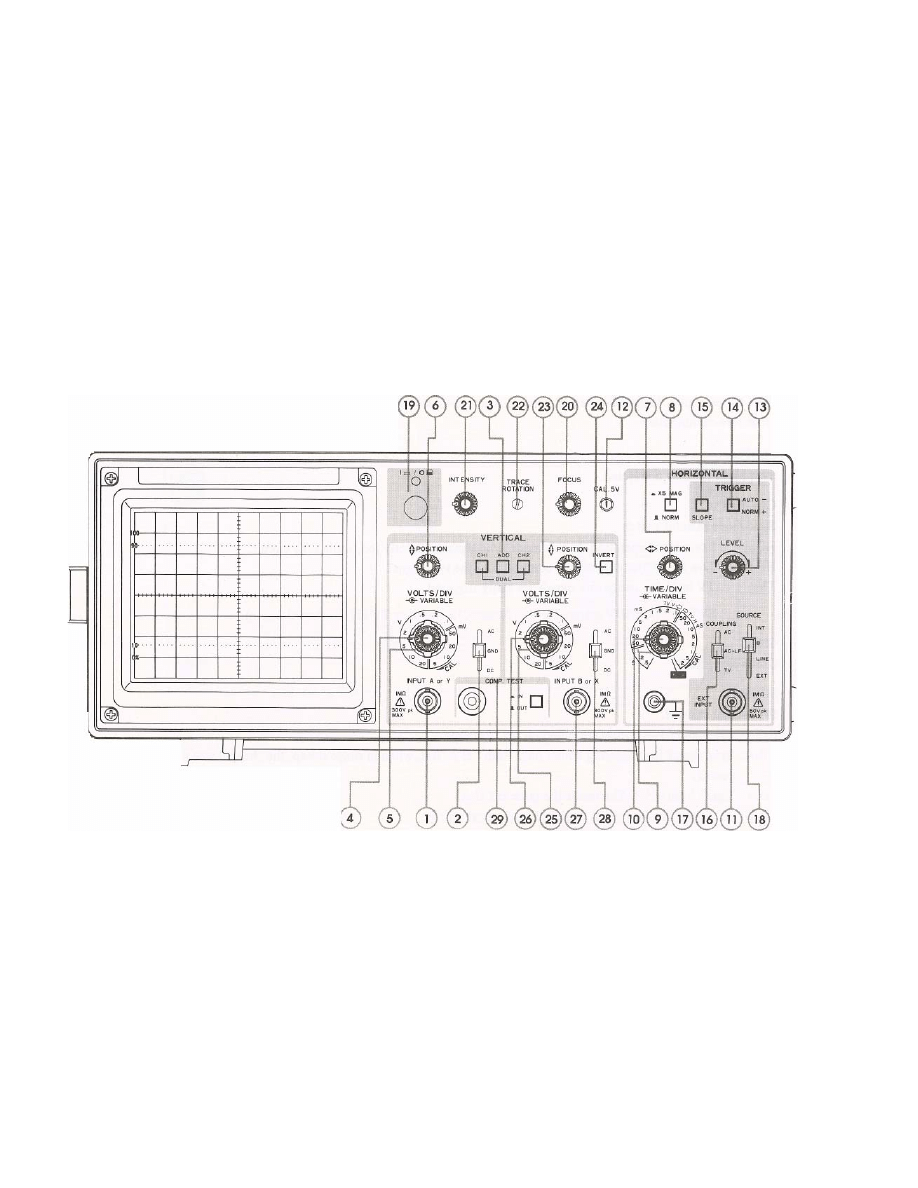
3-2 CONTROLS & INDICATIONS
1. VERTICAL
INPUT
Vertical input terminal for CH-A.
2. AC-GND-DC
Vertical input coupling for CH-A. In AC position, the DC component of input signal is blocked by a capacitor. In GND
position, the input terminal opens and the input of the internal amplifier is grounded. In DC position, the input terminal is
directly connected to the amplifier and all components of input signal are displayed.
3. MODE
CH-A: Waveforms of CH-A are displayed.
CH-B: Waveforms of CH-B are displayed.
DUAL: In the range from 0.5sec/DIV up to 1msec/DIV, both channels are chopped at about 200kHz.
In the range from 0.5msec/DIV up to 0.2 µsec/DIV, both channels are switched alternately.
ADD:
CH-A and CH-B signals are added. By Pushing (23) PUSH INVERT, SUB mode is obtained.
4. VOLTS/DIV VARIABLE for CH-A.
5. VOLTS/DIV
Vertical attenuator for CH-A. The scale is graduated in voltage per "DlV" of CRT screen area.
Calibrated voltage is indicated when the VARIABLE is turned fully clockwise.
Selectable in 10 calibrated ranges from 5mV/DIV to 20V /DIV.
6. VERTICAL POSITION
Vertical position adjuster for CH-A.
7. HORIZONTAL
POSITION
Horizontal position adjustor.
8. PUSH X5 MAG
When pushed, SWEEP TIME is magnified by 5.
6

9. SWEEP
TIME/DIV
Horizontal sweep time selector. It selects sweep times of 0.2 µsec/DIV to 0.5 sec/DIV in 20 calibrated steps. X-Y
operation is possible by turning the knob fully clockwise to CH-B.
Change over between CHOP and ALTERNATE is also accomplished automatically by this selector in DUAL MODE.
10. SWEEP TIME/DIV VARIABLE
11. EXT.TRIG
Input for external triggering signal.
12. CAL
Calibration voltage terminal. Calibration voltage is 0.5Vp-p of about 1 kHz square wave.
13. TRIGGERING LEVEL
LEVEL control adjusts sync phase to determine the starting point of sweep on the slope of displayed waveform.
14. PUSH AUTO
By pushing LEVEL knob toward you, auto-sweep is effected; the sweep is set in free-running state even when no input
signal is applied, with trace line displayed on CRT.
With trigger signal, triggered-sweep is effected where sync level is adjustable. When sync level is deviated, the sweep is
set in free-running state.
15. SLOPE + , -
Sync slope polarity is selected.
16. COUPLING
Sync mode selector switch.
AC:
For normal operation. In this mode sync signal is directly fed to the sync circuit.
HF REJ: Low Pass Filter cuts off RF composite of the sync signal.
TV:
TV or Video composite signals are easily triggered.
SWEEP TIME/DIV selects TV-V (50 µsec - 0.1 msec) or TV-H (50 µsec – 0.2 msec)
17. GND
Ground terminal.
18. SOURCE
Sync signal selector.
INT:
CH-A and CH-B signals are added on for triggering.
CH-A: Sync signal for triggering comes only from CH-A. But, when in single sweep, the channel selected by MODE has
priority.
CH-B: Signal from CH-B. The rest is the same as CH-A.
LINE: AC power line waveform is used as sync signal source.
EXT:
The signal hooked into EXT TRlG becomes the sync signal source.
19. POWER SWITCH
On or off.
20. FOCUS
Focus control to obtain optimum waveform display.
21. INTENSITY
Adjust the brightness of waveform for easy viewing.
22. TRACE ROTATOR
The earth magnetics effect the trace line. Rotate this with a screw driver for proper trace line.
7
23. CH-B POSITION
CH-B vertical position control.
24. PUSH INVERT
When pushed, the CH-B vertical polarity is inverted. This facilitates SUB MODE measurement at ADD MODE.
25. VOLTS/DIV
Vertical attenuator for CH-B.
26. VARIABLE
27. VERTICAL INPUT
Vertical input for CH-B.
28. AC-GND-DC
For CH-B, same as (2).
29. COMP. TEST
Switch to change from oscilloscope mode to component tester mode.
For component testing set the SWEEP TIME/DIV (9) to the X-Y setting (fully clockwise) and both vertical coupling
switches (2) (28) to the GND position.
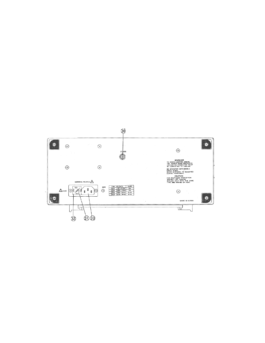
30. Z AXIS
External Intensity Modulation Input.
31. FUSE HOLDER
Proper ampere fuse must be in compartment
32. VOLTAGE SELECTOR
Proper line voltage must be selected where this oscilloscope is used.
33. RECEPTACLE for AC line cable.
3-3 TRIGGERING
Generally, triggered oscilloscopes have the following circuits to display stable waveform on the screen.
Vertical input signal or integral number related signal is used for a sync pulse signal, which is used as a triggering signal. This
signal stabilizes the waveform display. However, this triggering must be exactly synchronized to the vertical input signal. And all the
knobs should be correctly used.
This model has 4 knobs to control triggering. They are LEVEL, SLOPE, SYNC and SOURCE.
8

(SOURCES)
When the vertical input signal is supplied to the internal SYNC circuit, it is called INTERNAL TRIGGER.
When the same signal or integral number related signal is applied into the SYNC circuit through EXT TRIG input, it is refered as
EXTERNAL TRIGGER. In this model INT, CH-A and CH-B of SOURCE switch are internal triggers. The internal trigger signal is
amplified in the vertical amplifier and triggering becomes easy.
LINE: The AC power line waveform is supplied to the SYNC circuit as a triggering source.
EXT: When SOURCE is turned to EXT, it becomes external trigger which has namely 3 benefits.
1. Triggering signal receives no effects from the vertical circuits.
EX. Triggering level need be readjusted when VOLTS/DIV knobs are turned because the sync source voltage changes. In
such case, unless the external trig input voltage is changed, triggering is very stable and free from vertical controls.
2. Input signal can be easily delayed by the use of the delaying function of a pulse generator.
3. Composite signal or modulated signal can be easily triggered by the signal which composes the composite signal.
(SYNC)
This switch has a selection of the sync circuit coupling. At AC position it becomes AC coupling and DC composite is isolated for
stabilized synchronization. HF REJ has a low pass filter to eliminate RF noise interference to synchronization. At TV position either
vertical or horizontal sync signal isolation circuit works to ensure the TV signal triggering.
Selection of TV-V or TV -H is done by SWEEP TIME/DIV switch.
(SLOPE)
SLOPE switch +, - selects the triggering source signal slope of positive or negative.
At TV sync, triggering point is set to sync pulse rising time or falling time.
(LEVEL)
When this knob is pushed it becomes AUTO for free running without the input signal for 0 level reference. When a signal is applied
to the input, turn this knob for stable triggering.
3-4 X-Y OPERATION
For some special cases, this instrument is specially designed for easy X-Y application. Simply turn SWEEP TIME/DIV switch to
CH-B. Then all CH-B functions work as horizontal amplifier, whereas CH-A remains as vertical amplifier.
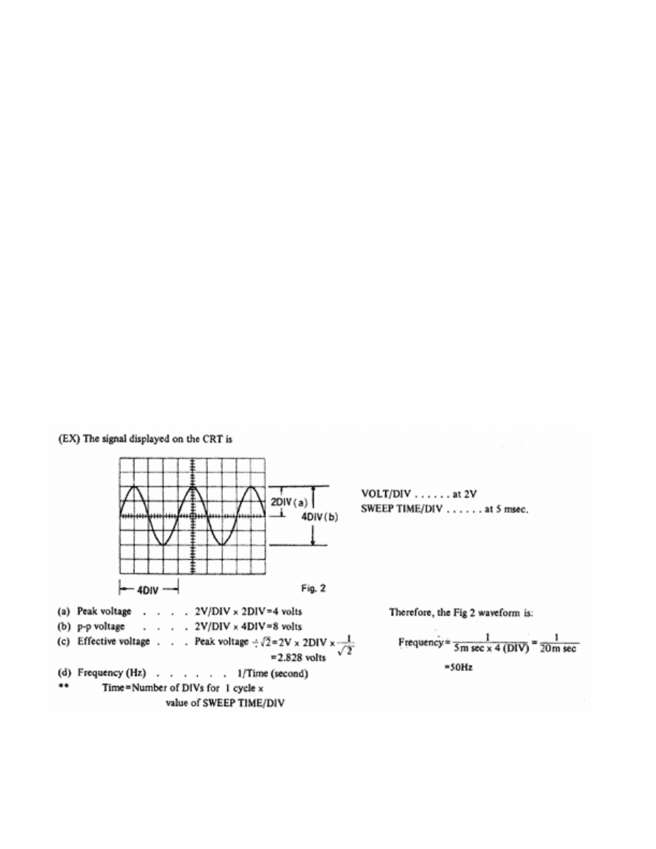
3-5 CALIBRATED VOLTAGE MEASUREMENTS
Peak voltages, peak-to-peak voltages, DC voltages and voltages of a specific portion of a complex waveform can be measured
using this instrument as a voltmeter. Voltages can be measured whenever waveforms are observed using either CH-A or CH-B
inputs. Proceed as follows:
1. Set VARIABLE control fully clockwise to CAL position, then set VOLTS/DIV control to display the Waveform in proper size
to be observed. Vertical POSITION controls may be turned to obtain division reference.
2. For DC or complex signals, set the input switch to GND, and adjust the vertical POSITION control to a convenient
reference level. Set the switch to DC and observe the amount of deflection. A positive voltage will deflect trace upwards: a
negative voltage will deflect the trace downward. To calculate the voltage reading, multiply the vertical deflection (by
division) by the setting of the VOLTS/DIV switch.
NOTE: WHEN A PROBE (10:1) IS USED, THE WAVEFORM DISPLAY IS ONLY 1/10 OF THE ACTUAL VOLTAGE MEASURED.
3-6 DUAL TRACE WAVEFORM OBSERVATION
MODE switch to be turned to DUAL. Other procedures are in the same manner as mentioned above.
3-7 TV SIGNAL SYNCHRONIZATION
Set TRIGGERING SYNC to TV (+ or -), then specially designed circuitry provides easy triggering for complexed TV frame and line
signal. TV frame and line waveform are easily obtained by simply tuning SWEEP TIME/DIV control.
9
3-8 ADD & SUB MEASUREMENTS
Simply turn MODE switch to ADD, added waveform of CH-A and CH-B is displayed.
With this MODE at ADD position, subtracted waveform is obtained by pulling INVERT knob which inverts the polarity of CH-B.
3-9 APPLICATIONS
This is a dual trace oscilloscope which has full capability of single trace mode. Thanks to the dual-trace functions, various effective
measurements are feasible.
[SINGLE-TRACE APPLICATIONS]
Either Channel A or Channel B can be used for single-trace operation. Channel A is referred to hereunder for simplicity
Set controls:
AC-GND-DC
AC
MODE
CH-A
SYNC
NORM
+
SOURCE INT
PROBE
to CH-A INPUT Jack
Connect the tip of the probe to the point in the circuit where the wave form is to be measured, and its ground clip to the chassis or
the ground part.
CAUTION!!! THE PEAK-TO-PEAK VOLTAGE AT THE POINT OF MEASUREMENT SHOULD NOT EXCEED 600 VOLTS.
3-9-1 AC VOLTAGE AND FREQUENCY MEASUREMENT
When measuring voltage and frequency, set VOLTS/DIV VARIABLEs (4), (25) and SWEEP TIME/DIV VARIABLE (9) at their
calibrated detent points (clockwise).
NOTE: The input of this oscilloscope is 1M
Ω shunted by 20pF capacitance. When the probe is used in 10:1 attenuation, the
impedance becomes 10M
Ω shunted by 15pF. Then the voltage reading must be multiplied by 10.
10
3-9-2 DC VOLTAGE MEASUREMENT
AC-GND-DC being at AC position, only AC was displayed on the CRT screen. For DC Measurement, set the switch to GND and
push the TRIGGERING LEVEL knob (13) for a trace line, which must be positioned at a certain place as 0 volt reference.
After that, turn the switch to DC. Then, the trace line shifts up or down. The value of movement is the DC voltage.
DC voltage = Shift (DIV) x VOLTS/DIV
When the trace line shifts up-ward, the polarity is (+), and down-ward is (-).
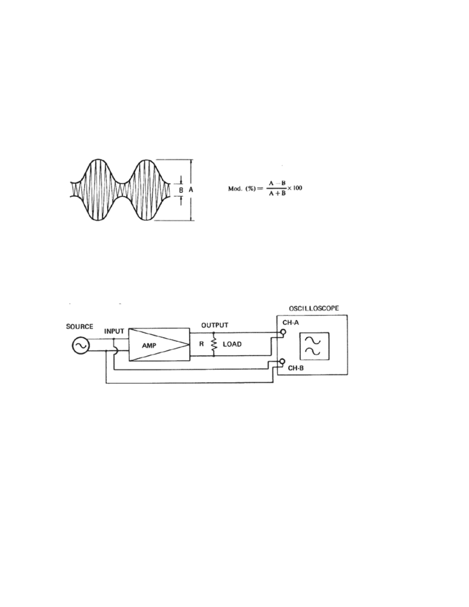
3-9-3 AM MODULATION MEASUREMENT
There are various ways of measurements, but herein this manual the envelope method is introduced. This method is applicable
when the carrier frequency is within the frequency bandwidth of the oscilloscope. See Fig. 3.
Fig.3
3-9-4 DUAL-TRACE APPLICATIONS
MODE switch being turned to DUAL, both Channel A and Channel B works simultaneously.
Then, comparison of two relative signals are easily done such as level, waveforms, phase, etc.
3-9-5 LEVEL COMPARISON
(EX) OUTPUT/INPUT of an amplifier
Fig.4
With the connections of the Fig. 4 set the displays of CH-A and CH-B the same (POSITION controls be adjusted to place CH-B
waveform onto CH-A). Then the difference between displays of CH-A VOLTS/DIV and CH-B's is the gain of the amplifier. If the
two signals do not match each other even when variable controls are adjusted, the difference is the distortion caused in the
amplifier. Then, simply turn the MODE switch to ADD and push INVERT knob for invert (SUB MODE), for viewing only distortion.
When there is no distortion originated in the amplifier, a straight trace line is displayed in SUB MODE.
3-9-6 REPAIRING STEREO SYSTEMS
Every stereo equipment has two symmetrical amplifier circuits.
So, simultaneous comparison of the same stages makes it so easy to locate defective point.
3-9-7 TV SERVICING
Triggered oscilloscope is indispensable. This model has the very convenient TV SYNC circuits of TV-V (Frame) and TV-H (line) for
accurate synchronization to view VIDEO SIGNAL, BLANKING PEDESTALS, VITS and Vertical/Horizontal SYNC PULSES.
11
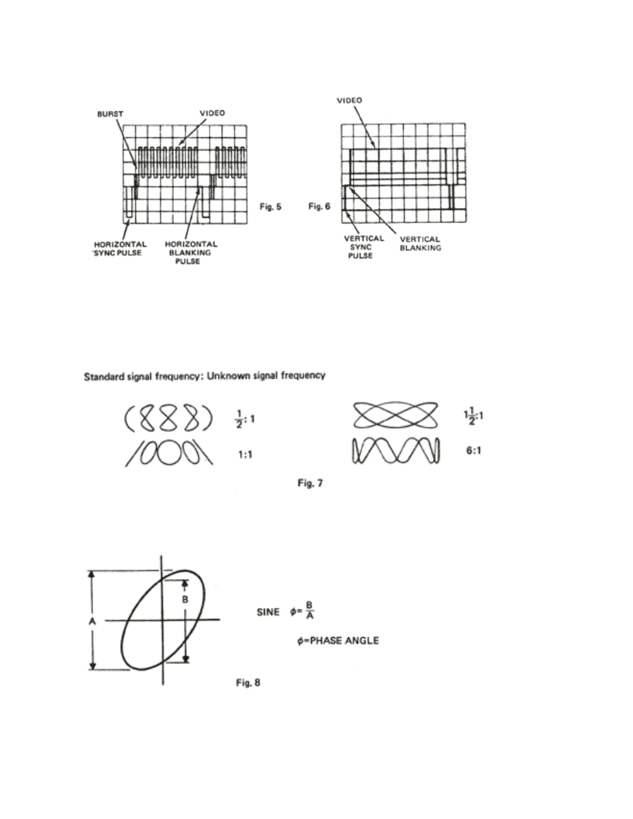
3-9-8 COMPOSITE VIDEO ANALYSIS
The most important waveform in TV servicing is the composite signal consisting of the video signal, the blanking pedestals, and
sync pulses. Fig. 5 and Fig. 6 show composite signals synchronized with horizontal sync pulses and vertical blanking pulses.
3-9-9 MEASUREMENT OF FREQUENCY BY X-Y
Simply turn SWEEP/DIV switch to CH-B for X-Y operation. Then CH-A becomes Y axis and CH-B X axis. Connect a standard
frequency signal to CH-B and unknown signal to CH-A. Lissajous figure is displayed on the screen as shown in Fig. 7.
3-9-10 PHASE MEASUREMENT
In X-Y function, apply two signals to each CH-A and CH-B. Calculate according to the formula.
3-9-11 PHOTOGRAPH
CRT CAMERA (using Polaroid film) exact hood size camera for this oscilloscope is available.
12
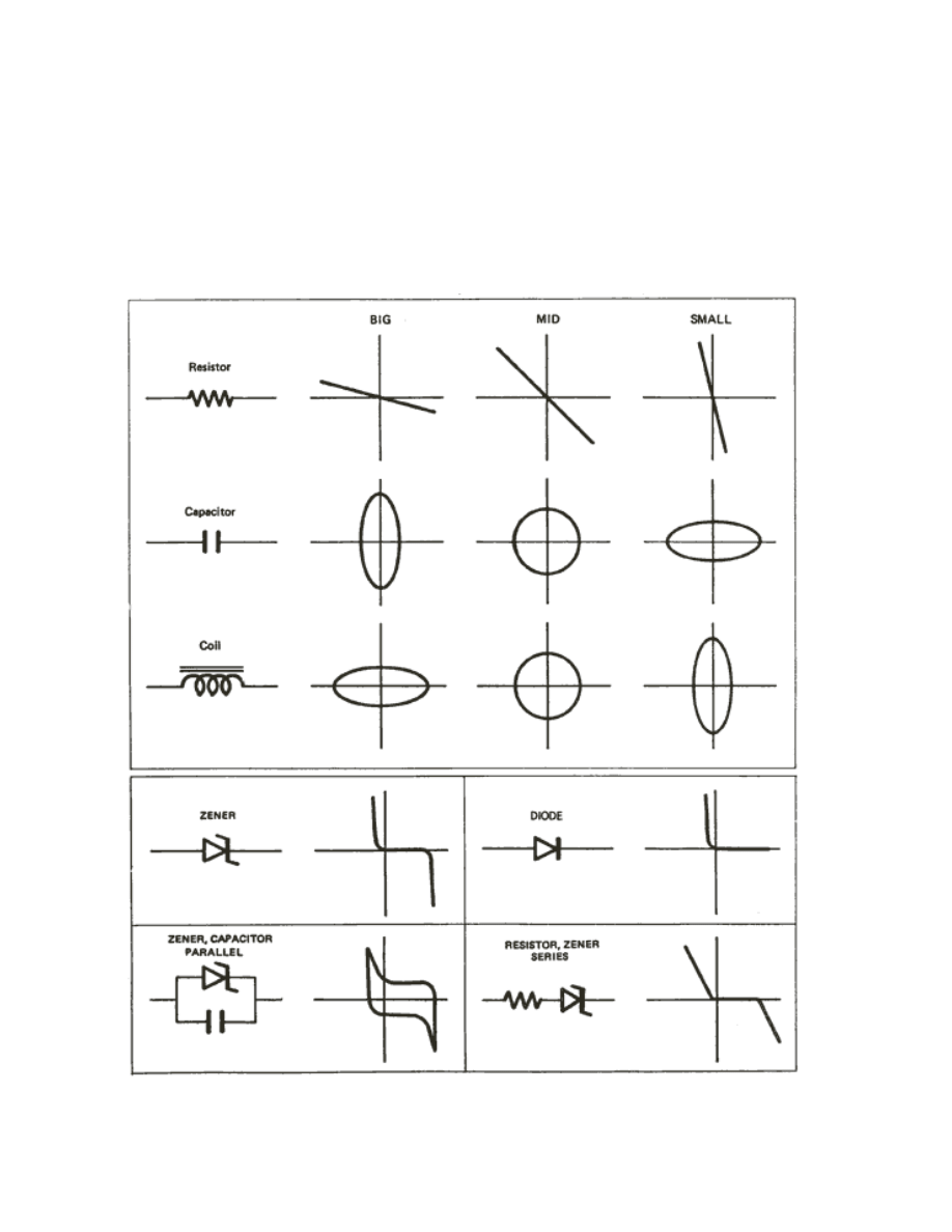
3-9-12 COMPONENT TEST
Turn SWEEP TIME/DIV switch to the X-Y mode (fully clockwise) and set both vertical coupling switches (2) (28) to the GND
position as well as setting the both VOLTS/DIV knob CH-1 to 2V/DIV, CH-2 to 5V/DIV, then push the COMP. TEST SW.
Components may be directly hooked to the COMP. TEST IN terminals or through lead wires.
Fig. 9 shows some reference displays.
NOTE: While in COMPONENT TEST operation, AC 9 VRMS is at the terminal for no load and about 2 mA will flow when they are
shorted.
Fig. 9
13

SECTION 4 CIRCUIT DESCRIPTION
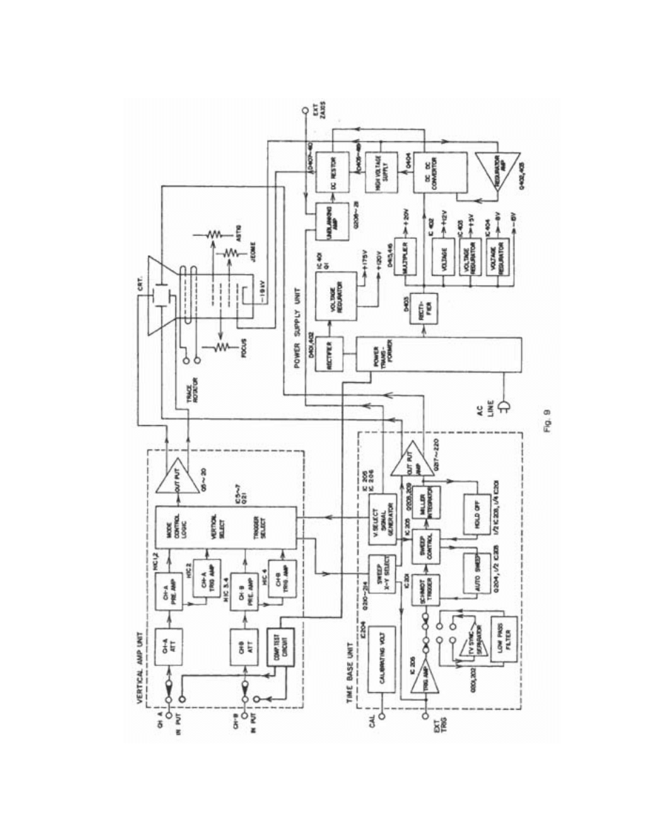
4-1 OUTLINES OF CIRCUIT
Block diagram of this model is as Fig. 9,
This oscilloscope is equipped with 2 identical input attenuators and preamplifiers. The input signal is attenuated to the required
level, amplified to the preamplifier, and led to the trigger pick off circuit, then to the switching circuit.
At the trigger pick off circuit, a part of the signal is picked up and fed to the trigger select logic for either CH-B, INT (CH-A + CH-B)
and led to the trigger amplifier of the TIME BASE Block.
The switching circuit consists of diode-gate and mode control logic to select CH-A, CH-B and DUAL.
Alter the switching circuit the signal is amplified, and goes through a cascade type final stage amplifier for CRT vertical deflector.
The trigger signal or an external trigger signal is amplified and reformed as a clock pulse to drive the following saw tooth generator
circuit, which consists of JKRS flip-flops and sweep controller, FET input Miller integrator, hold-off.
The tooth wave generated by the clock pulse, is led to a differential amplifier which, is equipped with a stabilized current supply,
then fed to CRT horizontal deflector.
For X-Y operation, CH-B input signal is led to the pick-off circuit, sweep X-Y selector, then horizontal final amplifier.
Q signal in the sweep control flip-flop and NAND of chopper rising edges are used for unblanking and chop-blanking. It is led to a
cascade amplifier with a constant current load, a DC producing circuit and then added on to a high voltage, and then fed between
the control grid and cathode of the CRT. The CRT is cut off during trace fly-back, and while waiting for trigger and chop change
over time.
The power supplies are all regulated.
A feed back type DC-DC converter is used for generating the stabilized high voltage to CRT.
4-2 VERTlCAL AMPLIFIER CIRCUIT
The vertical input signal fed from the BNC input terminal is controlled by the AC-GND-DC switch and applied to the 1st attenuator,
where 1/10 step (20dB) attenuation takes place. The out of input protection circuit Q1 (Q3) is fed to the DUAL FET through high
input impedance; DUAL FET is well DC balanced against temperature variation.
After being DC balanced, through VR1, 3, 4 (VR7, 9, 10), the output signal is fed to the diode switching circuit composed of D2-5,
16-19.
The mode logic circuit which is controlled by the MODE switch, makes the selection of dual-trace, single-trace, CHOP and ALT
possible. Dual-trace operation is obtained by the trigger select logic circuit driven by TRIG SOURCE switch, while the vertical
MODE switch works prior to TRIG SOURCE switch and selects a proper trigger signal for single-trace operation.
In single trace operation triggering is automatically logic controlled according to the vertical MODE switch prior to Trigger SOURCE
Selector.
In X-Y operation, controlled by the SWEEP TIME/DIV control, CH-B signal is supplied to the trigger amplifier and fed to the
horizontal amplifier as the X signal.
The vertical signal through diode switching circuit passes the limiter circuit of Q 5, 6 and D6-9 to obtain the adequate level, and
then is fed to the output amplifier composed of Q11-20. The output obtained is sufficiently amplified by the feedback-type amplifier
with the constant current circuit (Q15, 16, 19, 20). This amplifier is equipped with the booster (Q17, 18) for high frequency contents
to-obtain flat response signals. The signal is then fed to the vertical deflection plates of CRT.
14
15

4-3 HORIZONTAL/TIME' BASE CIRCUIT
Time Base circuit consists of trigger section, the saw-tooth section and amplifier section. The output from trigger select circuit is led
to sweep X-Y select circuit (Q210 - 214). This select circuit works as the internal trigger amplifier and the saw tooth wave amplifier
in normal operation, and as the amplifier for CH-B signal in X-Y operation. The internal trigger signal is being amplified by IC206
and then fed to schmidt circuit (1/2 IC 1). The external trigger signal is directly fed to IC206. With TRIG SOURCE switch set to HF
REJ, noises and high frequency components in the trigger source are eliminated. With TRIG SOURCE switch set to TV, IC output
is connected to TV sync separator (Q201, 202) to obtain horizontal sync signal (TVH) or vertical sync signal (TVV) and to supply it
to schmidt circuit. Changeover between TVH and TVV is automatically accomplished by the SWEEP TIME/DIV switch. The signal
in the schmidt trigger circuit is shaped into square waves and becomes clock pulses for sweep control gate (IC 205). The clock
pulse is also supplied to auto sweep (Q204, 1/2 IC203). With no trigger input, the output of the auto sweep circuit becomes low
level, and therefore sweep control gate starts automatic sweeping. With triggering input, or supply of clock pulse, the output of auto
sweep circuit becomes high level and the gate F.F. is inverted by the clock pulses and the Miller integrator becomes charged. Also,
the output of auto-circuit actuates Q223 ON/OFF. When the gate F.F. is inverted, and sets Q207 to OFF, the Miller integrator
determines the sweep time by the C/R time constant selected by the SWEEP TIME/DIV switch to obtain saw-tooth waves of
excellent linearity. When the output from the Miller integrator fully rises, the Hold-off F.F. is inverted and the sweep stops for the
time determined by the Hold-off time constant. When the Hold-off time passes, the next clock pulse is set in standby, mode and
thereby the sweep returns to the original status.
The output of this Miller integrator passes through sweep X-Y select circuit and is fed to the horizontal amplifier (Q217 - 220). In
this amplifier, by use MAG X5 switch, sweep time is expanded by factor of 5. With SWEEP TIME/DIV switch set to X-Y position,
sweep X-Y select circuit is switched to separate the Miller integrator from the horizontal amplifier and then the vertical CH-B input is
applied as horizontal input amplifier. In CHOP operation, blanking effects are given with the use of the horizontal Q output and
CHOP signal generator. In ALT operation, the effects are given by Q output.
The output from multivibrator of IC204 is shaped to obtain the calibrating voltage output. The variable resistor of VR203 is used to
adjust the output level of 0.5p-p.
16

SECTION 5 MAINTENANCE & ADJUSTMENTS
5-1 GENERAL
This section contains information for preventive maintenance, adjustment and calibration.
5-1-1 PREVENTIVE MAINTENANCE
Preventive maintenance consists of periodic cleaning, and recalibration of the oscilloscope. It should be performed on a regular
bases to keep the instrument in its best operational and appearance condition.
5-1-2 CLEANING
Accumulation of dirt, dust and grime should be removed whenever they become noticeable. The frequency of cleaning is largely
dependent upon the environment in which the instrument is used. Dirt on the outside covers may by removed with a soft cloth
moistened with a diluted household cleaning solution.
5-1-3 RECALIBRATION
Recalibration of the instrument at regular intervals will assure that measurements within the accuracy specification. It is
recommended that the instrument be recalibrated after 1000 hours of operation, or twice a year. The calibration procedures are
provided in the latter part of this section of the manual.
5-2 ADJUSTMENT AND CALIBRATION
Most of the problems resulting in a malfunction will be a defective component or a mechanical defect. Verify that the problem is not
due to an incorrect switch position. The CRT display can be a valuable aid in pinpointing the area of many problems. The defect of
any of the amplifiers, triggering circuit will be noticeable on the CRT.
Test Instruments Required
Instrument
Brief
Specification
1. Digital Voltmeter
Range: 0 to 1000V DC
2. 10:1 High Voltage Divider
Accuracy: Within 0.5% ± 2%
3. Square wave generator
1KHz – 1MHz, Reset time < 5 nS
4. Oscillator
1KHz – over 20MHz
5. TiMe Mark Generator
Purse ranges from 0.1µs to 0.5mS ± 1%
6. Cable
Male BNC to male BNC, 50
Ω
5-2-1 PREUMINARY PROCEDURE
1. Check that the 100V/117V/220V/240V/ and Voltage selector is properly set.
2. Turn the instrument on and allow at least 20 minutes warm-up before starting the adjustment procedure. For the best
overall accuracy, make adjustments in ambient temperature of +20°C to +30°C.
5-2-2 POWER SUPPLY UNIT ADJUSTMENTS
Some problems may result severe loading on the power supplies. The power supply unit for the this model comprises a DC to DC
converter. The normal operating frequency of the converter is approximately 40KHz. Modifying pulse width with the change of
loads, this converter assures the constant voltage supply. When the secondary voltage of the converter is incorrect, remove the
P4 and P7 connectors of the Power Supply unit for checking.
1. Voltage Adjustments
a) Connect Digital Voltmeter common (or -) lead to the 5th ground.
b) Connect Digital Voltmeter V.
Ω on (or +) lead to the 1st Pin +of D401.
c) Adjust VR406 until +200V supply gives reading of +200V ± 0.5V.
17
d) Transfer Digital Voltmeter V.
Ω (or +) lead to the 2nd pin on connector P403
e) Adjust VR401 for Digital Voltmeter reading of -1.9 KV ± 5V
f) Disconnect Digital Voltmeter.
2. Adjustments of intensity limit, Astingmatism, Trace Alignments.
a) Set Time/Div. switch to CH B position.
b) Center beam using Position (
↑↓).
c) Rotate Intensity to 10 o'clock position.
d) Adjust VR4OS (intensity limit adjustment) so beam is just extinguished.
e) Adjust INTENSITY to obtain normal spot brightness and FOCUS to center position.
f) Adjust Astingmatism adjustment, VR403 and jeome adjustment, VR404 to get a sharp, round dot.
g) Set TIME/DIV. switch to 0.5µs position.
h) When fly-back line appears on the CRT with trace line, adjust VR402 until the fly-back line is minimized
i)
Repeat step a to f
j)
Adjust trace rotator so that trace is parallel with horizontal graticule lines. Local magnetic field affects this setting.
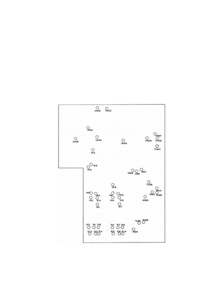
Fig. 10 ADJUSTMENT POINT
18

5-2-3 VERTICAL AMPLIFIER UNIT ADJUSTMENTS
1. Adjustments of preamplifier
a) Preliminary control setting: preset front panel controls as follows:
Intensity
Midrange
Focus Midrange
Vertical Mode
CH A
Volts/DIV (both)
10mV
AC-GND-DC (both) GND
Variable
Detent
Time/DIV.
0.5mS
Source
INT
SYNC
NORM +
Leyel
Midrange and pull auto
Position (All)
Midrange
b) Short TP terminal of V-PCB.
c) Adjust VR6 so that sweep lines could be at the center of CRT.
d) Open TP terminal
e) Use CH A Position (
↑↓) control to set trace on center horizontal graticule line.
f) Adjust VR1 (VR7 for CH B) for no trace shift while switching CH A Volts/Div control between 2mV and 10mV.
g) Adjust VR3 (VR9 for CH B) until no trace shift occurs when CH A Variable move between minimum and maximum
h) Rotate CH A Position (
↑↓) to 12 o'clock position and adjust VR4 (VR10 for CH B) so that sweep lines could be at the
center of CRT.
i)
Repeat steps e through h for CHB.
2. Adjustments of attenuator
a) Set CH A Volts/Div switch to 0.1V setting and Time/Div switch to 20µs setting.
b) Set vertical Mode switch to CH A
c) Connect square-wave generator (600
Ω output) to CH A input connector.
d) Set square-wave generator control for 1 KHz output with sufficient amplitude to produce 6 divisions of vertical
deflection.
e) Adjust TC1 (TC7 for CH B) compensation adjustments to achieve squarest corners on the displayed waveform.
f) Set square wave generator for 1 KHz signal 6 divisions of vertical deflection.
g) Adjust input capacitor adjustment TC2 (TC8 for CH B) for best possible waveform.
h) Set Volts/Div switch to 1V settings. Adjust square wave generator output for 1 KHZ and 6 divisions of vertical
deflection.
i)
Adjust TC3 (TC9 for CH B) compensation adjustment to achieve squarest corners on displayed waveform.
j)
Set square wave generator controls for 1 KHz output with sufficient amplitude to produce 6 divisions of vertical
deflection.
k) Adjust input capacitors TC4 (TC10 for CH B) for best possible wave form.
l)
Set Volts/Div switch to 10V settings. Adjust square wave generator output for 1 KHz and 6 divisions of vertical
displays.
m) Adjust TC5 (TC 11 for CH B) compensation adjustment to achieve squarest corners on displayed waveform.
n) Set square .wave generator control for 1 KHz output with sufficient amplitude to produce 6 division of vertical
deflection.
o) Adjust input capacitors TC6 (TC12 for CH B) for best possible waveform.
p) Repeat steps a) through o) for CH B.
q) Setting
19

Volts/Div {both)
0.1 V
CH A AC-GND-DC
DC
CH B AC-GND-DC
GND
Vertical Mode
CH A
Time/Div
1 µS
Source
INT
SYNC
NORM +
Level
Midrange and Pull Auto
r) Adjust square wave generator output for 100KHz and 6 division of vertical display.
s) Adjust TC13 until squarest waveform.
t) Adjust TC14 (CH-A) and TC15 (CH-B) until squarest waveform for over shoot and under shoot.
u) Adjust VR13 until no waveform distortion occurs when position (
↑↓) control between up and down.
3. Adjustment of Vertical gain'
a) Setting
Volts/Div (both)
2mV
Vertical Mode
CH A
AC-GND-DC (both)
DC
Time/Div
0.5mS
Source
INT
SYNC
NORM
+
Level
Midrange and Pull Auto
.
b) Connect Oscillator to CH A input connector.
c) Set Oscillator for 1KHz at exactly 10mV pop Amplitude.
d) Adjust vertical gain adjustment VR5 (VR11 for CH B) for exactly 5 divisions of vertical deflection. This ensures 3%
accuracy in the vertical amplifier.
e) Set vertical Mode to CH B.
f) Repeat steps b) through d) for CH B.
g) Set Time/Div. switch to CH B position and CH B Volts/Div switch to20mV setting. Center beam using position (
↑↓)
controls.
h) Connect Oscillator to CH B input connector and Set Oscillator for 1KHz at exactly 10mV P-P amplitude.
i)
Adjust VR 12 for exactly 5 divisions of horizontal deflection.
j)
Disconnect Oscillator.
20

21
5-2-4 Horizontal/Time Base Unit Adjustments.
1. Adjustment of Sweep Time/Div.
a) setting.
Volts/Div (both)
0.1mV
Vertical Mode
CH A
Time/Div
0.1mS
Source
INT
SYNC
NORM +
Level
Midrange and Pull Auto
b) Connect Time marker generator to CH A input connector and set generator for 0.1mS marker interval.
c) Adjust VR208 so that lie on vertical graticule lines.
d) Set generator for 1µS marker interval and Time/Div switch to 0.5 µS setting.
e) Adjust TC202 so that time marker again co-incide with vertical line of graticule.
f) Set generator for a 0.5 µS marker interval and Time/Div switch to 0.5 µS settings.
g) Adjust TC201 so that markers lie on Vertical graticule and adjust VR214 for realignment of the range of 0.2 µS / Div.
h) Set Time/Div switch to 0.1mS setting and set generator for a 0.1mS marker interval.
i)
Set 5 X MAG switch to push.
j)
Adjust VR2I2 for exactly 5 divisions to horizontal deflection and then push MAG switch.
k) Adjust VR7 to obtain the same center position when the display is magnified.
l)
Adjust of sweep linearity: Adjust VR210 so that sine wave could not be concentrated at one side under time
0.1mS/Div.
m) Adjustment of triggering: Adjust VR205 so that both (Sync + or -) start at the same point.
2. ADJUSTMENT OF X-AXIS (CH-B) POSITION
With SWEEP TIME/DIV. control set at CH-B, check if shift range is balanced when X-axis POSITION (CH-B VERTICAL
POSITION) is turned. If there is unbalance, Adjust VR209 and then Adjust VR211 to be at the center of X-axis.
3. ADJUSTMENT OF TRACE LINE LENGTH
Adjust VR2I3 to obtain the length of 11 DIV on CRT screen.
4. ADJUST VR201 VR202 AND VR203 for CALIBRATION
To be 0.5V P-P when 1 : 1 probe is connected to the terminal of front panel calibration under VOLT/DIV 0.1V and
TIME/DIV 0.1ms
5. ADJUST TC205 FOR 0.5 sec LENGTH
The length of trace line could be reached on the CRT surface when you input 0.5 µS pulse under TIME/DIV 0.5 µS range.
6. ADJUST TC204 FOR 0.5 sec/DIV MAG LINEARITY
Same as 3 adjustment after you draw PULL 5 X MAG SWITCH
7. Adjust VR215 for jittering.
8. Adjust TC203 for unblanking start position.
Document Outline
- SECTION 1 INTRODUCTION
- SECTION 2SPECIFICATION
- SECTION 3OPERATION
- 3-1 INITIAL OPERATION
- 3-2 CONTROLS & INDICATIONS
- 3-3 TRIGGERING
- 3-4 X-Y OPERATION
- 3-5 CALIBRATED VOLTAGE MEASUREMENTS
- 3-6 DUAL TRACE WAVEFORM OBSERVATION
- 3-7 TV SIGNAL SYNCHRONIZATION
- 3-8 ADD & SUB MEASUREMENTS
- 3-9 APPLICATIONS
- 3-9-1 AC VOLTAGE AND FREQUENCY MEASUREMENT
- 3-9-2 DC VOLTAGE MEASUREMENT
- 3-9-3 AM MODULATION MEASUREMENT
- 3-9-4 DUAL-TRACE APPLICATIONS
- 3-9-5 LEVEL COMPARISON
- 3-9-6 REPAIRING STEREO SYSTEMS
- 3-9-7 TV SERVICING
- 3-9-8 COMPOSITE VIDEO ANALYSIS
- 3-9-9 MEASUREMENT OF FREQUENCY BY X-Y
- 3-9-10 PHASE MEASUREMENT
- 3-9-11 PHOTOGRAPH
- 3-9-12 COMPONENT TEST
- SECTION 4 CIRCUIT DESCRIPTION
- SECTION 5MAINTENANCE & ADJUSTMENTS
Wyszukiwarka
Podobne podstrony:
cas test platform user manual
CARPROG Opel ECU programmer user manual
elm327 interface viecar obd2 bluetooth scanner user manual
autel power scan ps100 user manual
Chartplanner user manual
INPA User manual
all100 user manual
CARPROG user manual
FX2N 485 BD User's Manual JY992 Nieznany
mb sbc tool user manual
07 Altistart48 user manual
iphone user manual pdf
PRDM 0010 Upgrade user manual UPG 0001
TK105 GPS Tracker User Manual
ATDSK1118 User Manual
FX2N 232 IF User's Manual JY992D66701
Administrator User Manual
NMS KD 0017 en V01 03 N3000 IMC and ISC User Manual
więcej podobnych podstron