
84
ENGLISH
As a rule, the Altistart 48 control (CL1 - CL2) and power (1/L1 - 3/L2 - 5/L3) supplies must be
disconnected before any operation on either the electrical or mechanical parts of the
installation or machine.
During operation the motor can be stopped by cancelling the run command. The starter
remains powered up. If personnel safety requires prevention of sudden restarts, this electronic
locking system is not sufficient: fit a breaker on the power circuit.
The starter is fitted with safety devices which, in the event of a fault, can stop the starter and
consequently the motor. The motor itself may be stopped by a mechanical blockage. Finally,
voltage variations or line supply failures can also cause shutdowns.
If the cause of the shutdown disappears, there is a risk of restarting which may endanger
certain machines or installations, especially those which must conform to safety regulations.
In this case the user must take precautions against the possibility of restarts, in particular by
using a low speed detector to cut off power to the starter if the motor performs an
unprogrammed shutdown.
The products and equipment described in this document may be changed or modified at any
time, either from a technical point of view or in the way they are operated. Their description can
in no way be considered contractual.
This starter must be installed and set up in accordance with both international and national
standards. Bringing the device into conformity is the responsibility of the systems integrator
who must observe the EMC directive among others within the European Union.
The specifications contained in this document must be applied in order to comply with the
essential requirements of the EMC directive.
The Altistart 48 must be considered as a component: it is neither a machine nor a device ready
for use in accordance with European directives (machinery directive and electromagnetic
compatibility directive). It is the responsibility of the final integrator to guarantee conformity to
the relevant standards.

85
ENGLISH
Contents
Steps for setting up the starter ______________________________________________________ 86
Factory configuration _____________________________________________________________ 88
Preliminary recommendations ______________________________________________________ 89
Technical specifications ___________________________________________________________ 90
Operating recommendations _______________________________________________________ 91
Starter-motor combinations ________________________________________________________ 94
Dimensions ___________________________________________________________________ 100
Mounting recommendations _______________________________________________________ 102
Mounting in a wall-fixing or floor-standing enclosure ____________________________________ 103
Power terminals ________________________________________________________________ 104
Control terminals _______________________________________________________________ 109
Wiring/RUN - STOP commands ____________________________________________________ 110
Application diagram _____________________________________________________________ 111
Thermal protection ______________________________________________________________ 121
Display unit and programming _____________________________________________________ 125
Remote terminal option __________________________________________________________ 128
Settings menu (Set) _____________________________________________________________ 129
Protection menu (PrO) ___________________________________________________________ 134
Advanced settings menu (drC) _____________________________________________________ 138
I/O menu (IO) __________________________________________________________________ 142
2nd motor parameters menu (St2) __________________________________________________ 146
Communication menu (COP) ______________________________________________________ 150
Parameter displayed menu (SUP) __________________________________________________ 152
Compability table _______________________________________________________________ 155
Maintenance ___________________________________________________________________ 156
Faults - causes - remedies ________________________________________________________ 157
Configuration/Settings tables ______________________________________________________ 162
ENGLISH
86
Steps for setting up the starter
1 – Delivery of the Altistart 48
• Check that the starter reference printed on the label is the same as that on the delivery note corresponding
to the purchase order.
• Remove the Altistart 48 from its packaging and check that it has not been damaged in transit.
2 - Fit the Altistart 48 in accordance with the recommendations on
page 102 and page 103
3 - Connect the following to the Altistart 48:
• The control line supply (CL1 – CL2), ensuring that it is off
• The power line supply (1/L1 - 3/L2 - 5/L3), ensuring that it is off
• The motor (2/T1 - 4/T2 - 6/T3), ensuring that its coupling corresponds to the supply voltage
Note
: If a bypass contactor is used, connect it to L1 L2 L3 on the line supply side and to terminals A2 B2 C2
provided for this purpose on the Altistart 48. See the diagrams on page 112.
If the ATS48•••Q is used in the motor delta windings, follow the recommendations on page 92, page 93 and
the diagrams on page 113.
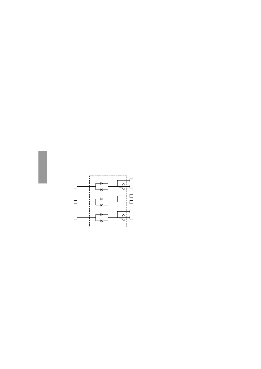
Block diagram of the power part of the ATS48:
1/L1
Tc1
Tc2
A2
ATS48
2/T1
3/L2
B2
4/T2
5/L3
C2
6/T3
Line
supply
2/T1 4/T2 6/T3
Motor
A2 B2 C2
Starter
bypass
87
ENGLISH
Steps for setting up the starter
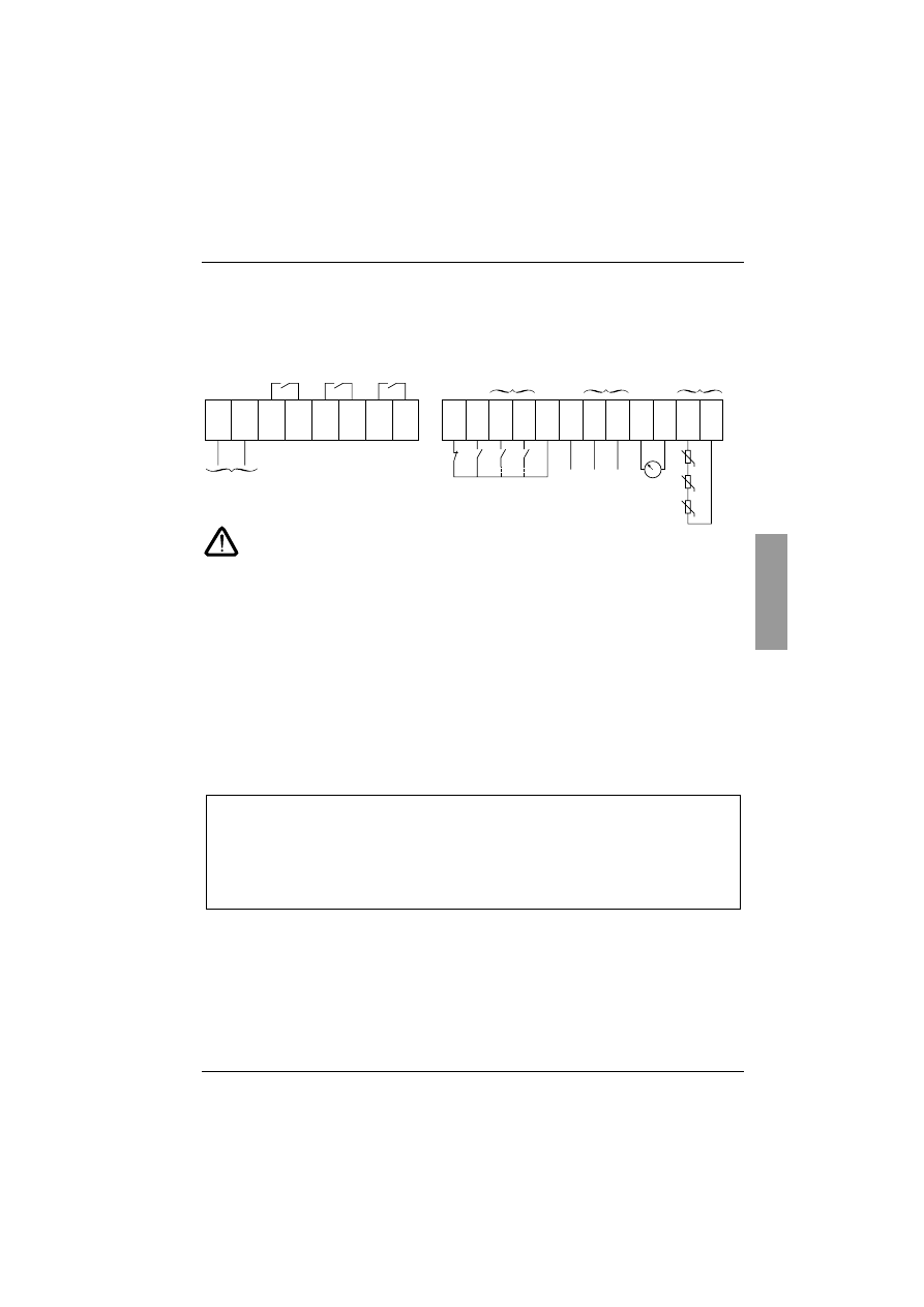
Factory configuration of the control terminals:
Connect the RUN and STOP commands and if necessary the other terminal inputs/outputs.
Stop at 1 (on) and RUN at 1 (on): start command.
Stop at 0 (off) and RUN at 1 or at 0: stop command.
4 - Essential information before starting up the Altistart 48:
Read the information on the motor rating plate. The values will be used to set parameter (In) in the SEt menu.
5 - Powering up the control part (CL1-CL2) without the power part and
without giving the run command
The starter displays: nLP (to indicate that the power is switched off).
6 - Powering up the power part (1/L1 - 3/L2 - 5/L3)
The starter displays: rdY (to indicate that the starter is powered up and ready).
Send a "RUN" command to start the system.
CL1
CL2
R1A
R1C
R2A
R2C
R3A
R3C
STOP
RUN
LI3
LI4
+24V
LO+
LO1
LO2
AO1
COM
PTC1
PTC2
Control supply
ATS48•••Q: 220 V - 400 V AC
ATS48•••Y: 110 V - 230 V AC
Fault relay
(R1F)
Starter bypass
relay
Motor
powered
Programmable
logic inputs
Logic input power
supply
Logic output
power supply
Programmable
logic outputs
Programmable
analog output
Inputs for PTC
probe
PTC probe
0 -20 mA
4 -20 mA
Motor
powered
Motor
thermal
alarm
Motor
current
Wire the fault relay in the line contactor power supply sequence in order to open the electrical
circuit in the event of a fault.
For further details refer to the application diagrams
.
0 V
3 x 250
Ω
The ATS 48 starter is factory-configured for a standard application which does not require specific
functions. It has motor protection class 10.
The settings can be changed by accessing the parameters as described on page 126.
In all cases the In parameter must be set to the current value indicated on the motor rating
plate.

ENGLISH
88
Factory configuration
Factory settings
The Altistart 48 is factory-set for the most common operating conditions:
• The ATS 48 is used on the motor line supply (it is not inserted as a delta connection in the motor windings)
• Nominal motor current In:
- ATS 48 •••Q: preset for a standard 400 V 4-pole motor
- ATS 48 •••Y: preset for NEC current, 460 V motor
• Limiting current (ILt): 400% of the motor current In
• Acceleration ramp (ACC): 15 seconds
• Initial torque on starting (tq0): 20% of the nominal torque
• Stop (StY): Freewheel stop (-F-)
• Motor thermal protection (tHP): class 10 protection curve
• Display: rdY (starter ready) with power and control voltage present, motor current operating
• Logic inputs:
- LI1: STOP
- LI2: RUN
- LI3: Forced freewheel stop (LIA)
- LI4: Forced local mode (LIL)
• Logic outputs:
- LO1: Motor thermal alarm (tA1)
- LO2: Motor powered (mI)
• Relay outputs:
- R1: Fault relay (rII)
- R2: Bypass relay at the end of starting
- R3: Motor powered (mI)
• Analog output:
- AO: Motor current (OCr, 0 - 20 mA)
• Communication parameters:
- Connected via the serial link, the starter has the logic address (Add) = "0"
- Transmission speed (tbr): 19200 bits per second
- Communication format (FOr): 8 bits, no parity, 1 stop bit (8nl)
If the above values are compatible with the application, the starter can be used without changing the settings.
89
ENGLISH
Preliminary recommendations
Handling and storage
To ensure the starter is protected before installation, handle and store the device in its packaging.
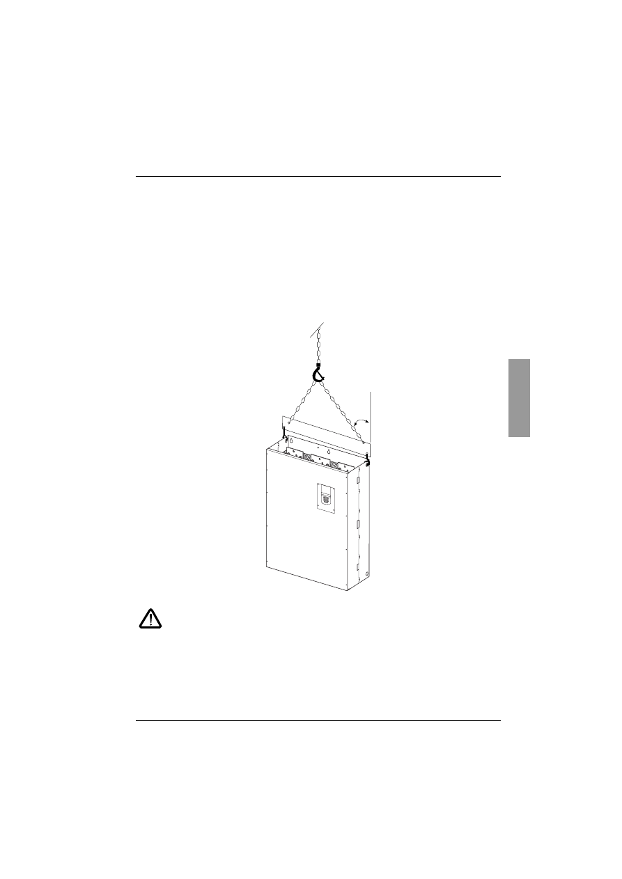
Handling on installation
The Altistart 48 range comprises 6 sizes of device, with various weights and dimensions.
Small starters can be removed from their packaging and installed without a handling device.
A handling device must be used with large starters; for this reason they are supplied with handling "lugs". The
precautions described below must be observed:
Do not handle the starter by the power rails
45¡
maxi

ENGLISH
90
Technical specifications
Environment
(1) ATS 48 starters with degree of protection IP00 must be fitted with a protective bar to
protect personnel against electrical contact
Degree of protection
• IP 20 for ATS 48D17• to C11•
• IP00 for ATS 48C14• to M12• (1)
Vibration resistance
Conforming to IEC 68-2-6:
• 1.5 mm peak from 2 to 13 Hz
• 1 gn from 13 to 200 Hz
Shock resistance
Conforming to IEC 68-2-27:
• 15 g, 11 ms
Maximum ambient pollution
Degree 3 conforming to IEC 947-4-2
Maximum relative humidity
93% without condensation or dripping water conforming to
IEC 68-2-3
Ambient temperature around the unit
Storage: -25°C to +70°C
Operation:
• -10°C to +40°C without derating
• up to +60°C, derating the current by 2% for each °C above 40°C
Maximum operating altitude
1000 m without derating (above this, derate the current by 0.5% for
each additional 100 m)
Operating position
Vertical at ± 10°
91
ENGLISH
Operating recommendations
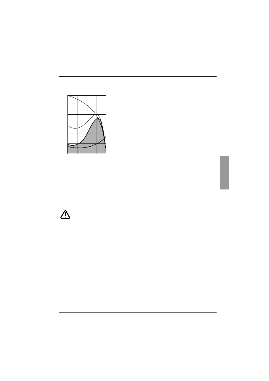
Available torque
Curves Ts and Is represent the direct line starting of an
asynchronous motor.
Curve Ta1 indicates the total torque range available with an
ATS 48, which is dependent on the limiting current ILt. The
progression of the starter is controlled by the motor torque within
this range.
Tr: Resistive torque, which must always be less than the Ts1
torque.
Selecting the soft start - soft stop unit
S1 motor duty corresponds to starting followed by operation at constant load enabling the thermal equilibrium
to be reached.
S4 motor duty corresponds to a cycle comprising starting, operation at constant load and an idle period. This
cycle is characterised by a load factor.
The Altistart 48 must be selected depending on the type of application ("standard" or "severe") and the nominal
power of the motor. "Standard" or "severe" applications define the limiting values of the current and the cycle
for motor duties S1 and S4.
Caution: Do not use the Altistart 48 upstream of loads other than motors (for example
transformers and resistors are forbidden). Do not connect power factor correction
capacitors to the terminals of a motor controlled by an Altistart 48
Standard application
Example: centrifugal pump
In standard applications, the Altistart 48 is designed to provide:
• in S1 duty: starting at 4 In for 23 seconds or starting at 3 In for 46 seconds from a cold state.
• in S4 duty: a load factor of 50% and 10 starts per hour, with 3 In for 23 seconds or 4 In for 12 seconds or
an equivalent thermal cycle.
In this case, the motor thermal protection must conform to protection class 10.
Severe application
Example: grinder
In severe applications, the Altistart 48 is designed for S4 duty with a load factor of 50% and 5 starts per hour
at 4 In for 23 seconds or an equivalent thermal cycle.
In this case, the motor thermal protection must conform to protection class 20. Current
In must not remain at
its factory setting
but must be set to the value indicated on the motor rating plate.
Note
: The starter can be oversized by one rating, for example by selecting an ATS 48D17Q for an 11 kW -
400 V motor in motor duty S4.
To do this, short-circuit the Altistart at the end of starting. This permits 10 starts per hour at 3 times In for
23 seconds maximum or equivalent and the thermal motor protection must conform to class 10.
0
0
0.25
0.5
0.75
1
N/Ns
Cr
Ts1
Ts
ILt
Is
ENGLISH
92
Operating recommendations
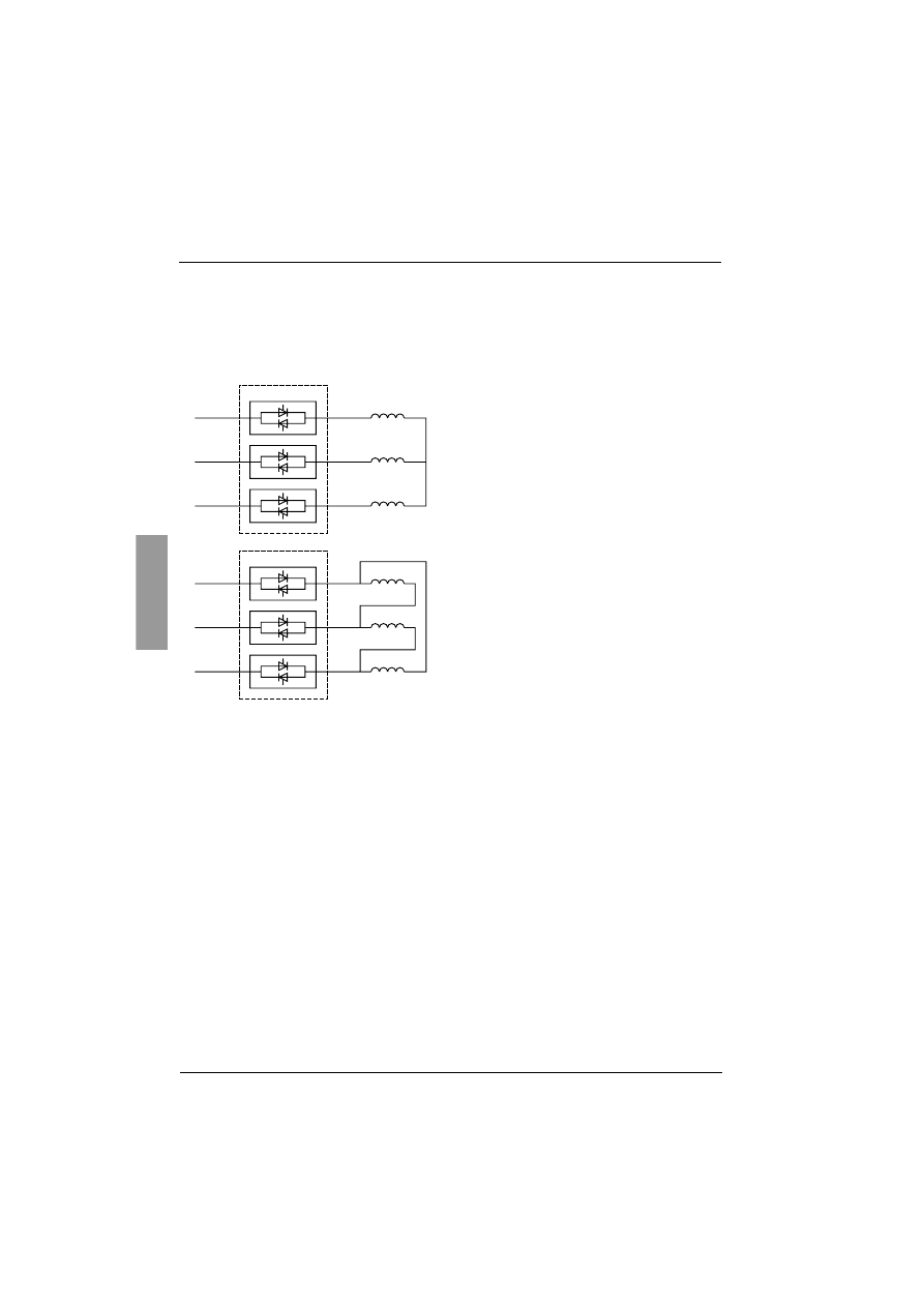
The Altistart 48 Q range (230-400 V) connected in line with the
motor or in the motor delta winding
The Altistart 48 connected in the motor supply line
L1
ATS48
V1
L2
V2
L3
1/L1
3/L2
5/L3
2/T1
4/T2
6/T3
V3
U1
V1
W1
The motor connection depends on the
supply voltage,
which in this
example is a star connection.
L1
ATS48
L2
L3
1/L1
3/L2
5/L3
2/T1
4/T2
6/T3
U1
U2
V1
V2
W1
W2
The motor connection depends on the
supply voltage,
which in this
example is a delta connection.
93
ENGLISH
Operating recommendations
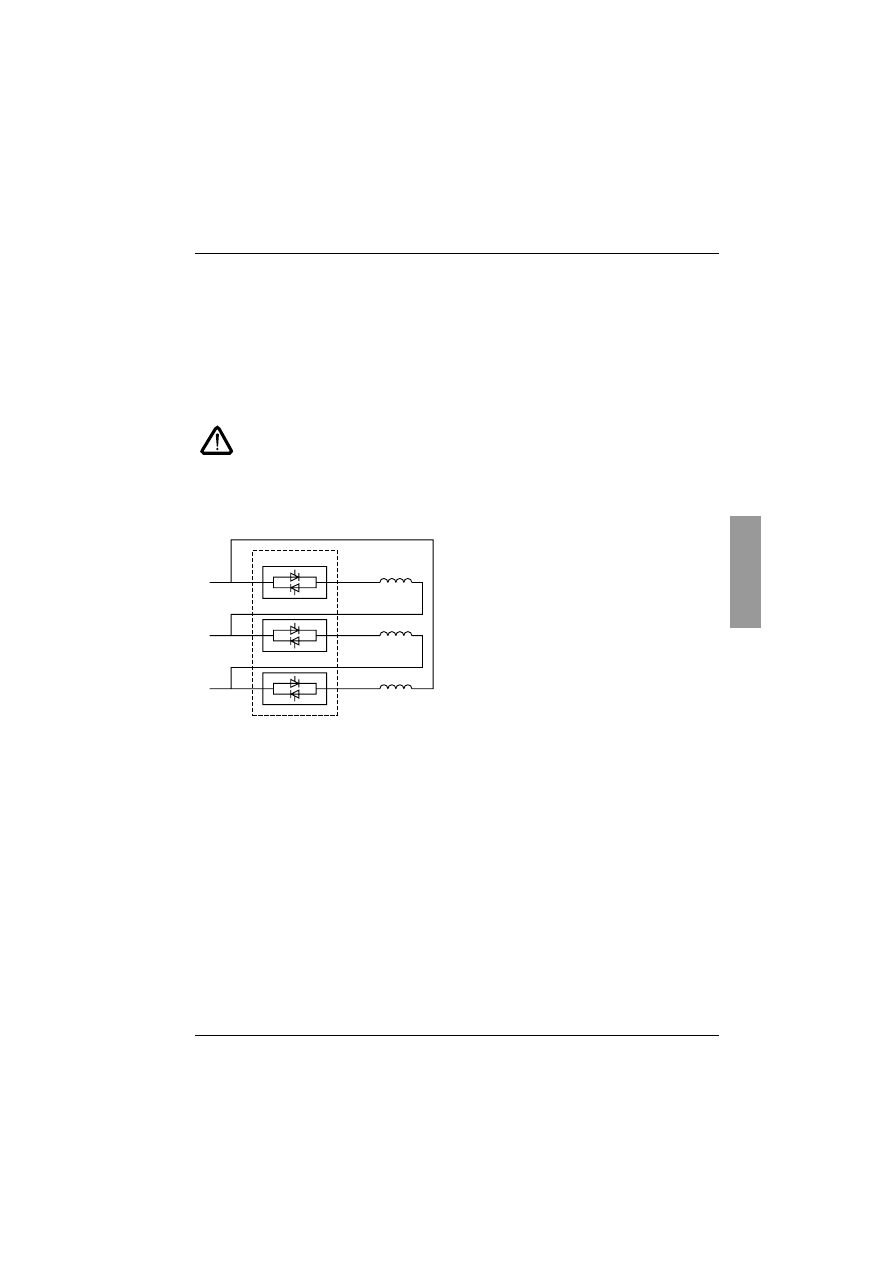
The Altistart 48 connected in the motor delta winding in series with each
winding
ATS48•••Q starters connected to motors with delta connections can be inserted in series in the motor windings.
They are powered by a current which is less than the line current by a factor of
√
3, which enables a starter with
a lower rating to be used.
This option can be configured in the Advanced settings menu (dLt = On).
The nominal current and limiting current settings as well as the current displayed during operation are on-line
values and so do not have to be calculated by the user.
The Altistart 48 can only be connected in the motor delta winding for ATS48•••Q starters. This
means that:
- only freewheel stopping is possible
- cascading is not possible
- preheating is not possible
See the tables on page 94 for more information about starter-motor combinations.
Example:
A 400 V - 110 kW motor with a line current of 195 A (nominal current for the delta connection).
The current in each winding is equal to 195/1.7 or 114 A.
The rating is determined by selecting the starter with a maximum permanent nominal current just above this
current, i.e. 140 A (ATS48C14Q for a standard application).
To avoid having to calculate the rating in this way, use the tables on page 96 and 97 which indicate the rating
of the starter corresponding to the motor power for each application type.
L1
ATS48•••Q
L2
L3
1/L1
3/L2
5/L3
2/T1
4/T2
6/T3
U1
U2
V1
V2
W1
W2
Connection in the motor delta
winding

ENGLISH
94
Starter-motor combinations
Standard application, 230/400 V supply, starter with
line connection
The nominal motor current In must not exceed the max. permanent current in class 10.
(1) Value not indicated when there is no corresponding standardised motor.
Temperature derating
The information in the table above is based on operation at a maximum ambient temperature of 40°C.
The ATS 48 can be used up to an ambient temperature of 60°C as long as the max. permanent current in class
10 is derated by 2% for each degree above 40°C.
Example: ATS 48D32Q at 50°C derated by 10 x 2% = 20%, 32 A becomes 32 x 0.8 = 25.6 A (max. nominal
motor current).
Motor
Starter 230/400 V (+ 10% - 15%) - 50/60 Hz
Nominal motor power
Max. permanent
current in class 10
ICL
rating
Starter reference
230 V
400 V
kW
kW
A
A
4
7.5
17
17
ATS 48D17Q
5.5
11
22
22
ATS 48D22Q
7.5
15
32
32
ATS 48D32Q
9
18.5
38
38
ATS 48D38Q
11
22
47
47
ATS 48D47Q
15
30
62
62
ATS 48D62Q
18.5
37
75
75
ATS 48D75Q
22
45
88
88
ATS 48D88Q
30
55
110
110
ATS 48C11Q
37
75
140
140
ATS 48C14Q
45
90
170
170
ATS 48C17Q
55
110
210
210
ATS 48C21Q
75
132
250
250
ATS 48C25Q
90
160
320
320
ATS 48C32Q
110
220
410
410
ATS 48C41Q
132
250
480
480
ATS 48C48Q
160
315
590
590
ATS 48C59Q
(1)
355
660
660
ATS 48C66Q
220
400
790
790
ATS 48C79Q
250
500
1000
1000
ATS 48M10Q
355
630
1200
1200
ATS 48M12Q
M

95
ENGLISH
Starter-motor combinations
Severe application, 230/400 V supply, starter with
line connection
The nominal motor current In must not exceed the max. permanent current in class 20.
(1) Value not indicated when there is no corresponding standardised motor.
Temperature derating
The information in the table above is based on operation at a maximum ambient temperature of 40°C.
The ATS 48 can be used up to an ambient temperature of 60°C as long as the max. permanent current in class
20 is derated by 2% for each degree above 40°C.
Example: ATS 48D32Q at 50°C derated by 10 x 2% = 20%, 22 A becomes 22 x 0.8 = 17.6 A (max. nominal
motor current).
Motor
Starter 230/400 V (+ 10% - 15%) - 50/60 Hz
Nominal motor power
Max. permanent
current in class 20
ICL
rating
Starter reference
230 V
400 V
kW
kW
A
A
3
5.5
12
17
ATS 48D17Q
4
7.5
17
22
ATS 48D22Q
5.5
11
22
32
ATS 48D32Q
7.5
15
32
38
ATS 48D38Q
9
18.5
38
47
ATS 48D47Q
11
22
47
62
ATS 48D62Q
15
30
62
75
ATS 48D75Q
18.5
37
75
88
ATS 48D88Q
22
45
88
110
ATS 48C11Q
30
55
110
140
ATS 48C14Q
37
75
140
170
ATS 48C17Q
45
90
170
210
ATS 48C21Q
55
110
210
250
ATS 48C25Q
75
132
250
320
ATS 48C32Q
90
160
320
410
ATS 48C41Q
110
220
410
480
ATS 48C48Q
132
250
480
590
ATS 48C59Q
160
315
590
660
ATS 48C66Q
(1)
355
660
790
ATS 48C79Q
220
400
790
1000
ATS 48M10Q
250
500
1000
1200
ATS 48M12Q
M

ENGLISH
96
Starter-motor combinations
Standard application, 230/400 V supply, starter with delta
connection
The nominal motor current In must not exceed the max. permanent current in class 10.
(1) Value not indicated when there is no corresponding standardised motor.
Temperature derating
The information in the table above is based on operation at a maximum ambient temperature of 40°C.
The ATS 48 can be used up to an ambient temperature of 60°C as long as the max. permanent current in class
10 is derated by 2% for each degree above 40°C.
Example: ATS 48D32Q at 50°C derated by 10 x 2% = 20%, 55 A becomes 55 x 0.8 = 44 A (max. nominal motor
current).
Motor
Starter 230/400 V (+ 10% - 15%) - 50/60 Hz
Nominal motor power
Max. permanent
current in class 10
ICL
rating
Starter reference
230 V
400 V
kW
kW
A
A
7.5
15
29
29
ATS 48D17Q
9
18.5
38
38
ATS 48D22Q
15
22
55
55
ATS 48D32Q
18.5
30
66
66
ATS 48D38Q
22
45
81
81
ATS 48D47Q
30
55
107
107
ATS 48D62Q
37
55
130
130
ATS 48D75Q
45
75
152
152
ATS 48D88Q
55
90
191
191
ATS 48C11Q
75
110
242
242
ATS 48C14Q
90
132
294
294
ATS 48C17Q
110
160
364
364
ATS 48C21Q
132
220
433
433
ATS 48C25Q
160
250
554
554
ATS 48C32Q
220
315
710
710
ATS 48C41Q
250
355
831
831
ATS 48C48Q
(1)
400
1022
1022
ATS 48C59Q
315
500
1143
1143
ATS 48C66Q
355
630
1368
1368
ATS 48C79Q
(1)
710
1732
1732
ATS 48M10Q
500
(1)
2078
2078
ATS 48M12Q
M

97
ENGLISH
Starter-motor combinations
Severe application, 230/400 V supply, starter with delta
connection
The nominal motor current In must not exceed the max. permanent current in class 20.
(1) Value not indicated when there is no corresponding standardised motor.
Temperature derating
The information in the table above is based on operation at a maximum ambient temperature of 40°C.
The ATS 48 can be used up to an ambient temperature of 60°C as long as the max. permanent current in class
20 is derated by 2% for each degree above 40°C.
Example: ATS 48D32Q at 50°C derated by 10 x 2% = 20%, 38 A becomes 38 x 0.8 = 30.4 A (max. nominal
motor current).
Motor
Starter 230/400 V (+ 10% - 15%) - 50/60 Hz
Nominal motor power
Max. permanent
current in class 20
ICL
rating
Starter reference
230 V
400 V
kW
kW
A
A
5.5
11
22
29
ATS 48D17Q
7.5
15
29
38
ATS 48D22Q
9
18.5
38
55
ATS 48D32Q
15
22
55
66
ATS 48D38Q
18.5
30
66
81
ATS 48D47Q
22
45
81
107
ATS 48D62Q
30
55
107
130
ATS 48D75Q
37
55
130
152
ATS 48D88Q
45
75
152
191
ATS 48C11Q
55
90
191
242
ATS 48C14Q
75
110
242
294
ATS 48C17Q
90
132
294
364
ATS 48C21Q
110
160
364
433
ATS 48C25Q
132
220
433
554
ATS 48C32Q
160
250
554
710
ATS 48C41Q
220
315
710
831
ATS 48C48Q
250
355
831
1022
ATS 48C59Q
(1)
400
1022
1143
ATS 48C66Q
315
500
1143
1368
ATS 48C79Q
355
630
1368
1732
ATS 48M10Q
(1)
710
1732
2078
ATS 48M12Q
M

ENGLISH
98
Starter-motor combinations
Standard application, 208/690 V supply, starter with
line connection
The nominal motor current In must not exceed the max. permanent current in class 10.
(1) Value not indicated when there is no corresponding standardised motor.
Temperature derating
The information in the table above is based on operation at a maximum ambient temperature of 40°C.
The ATS 48 can be used up to an ambient temperature of 60°C as long as the max. permanent current in class
10 is derated by 2% for each degree above 40°C.
Example: ATS 48D32Y at 50°C derated by 10 x 2% = 20%, 32 A becomes 32 x 0.8 = 25.6 A (max. nominal
motor current).
Motor
Starter 208/690 V (+ 10% - 15%) - 50/60 Hz
Nominal motor power
Max. permanent
current in class
10
ICL
rating
Starter
reference
208 V 230 V 440 V 460 V 500 V 575 V 690 V
HP
HP
kW
HP
kW
HP
kW
A
A
5
5
7.5
10
9
15
15
17
17
ATS 48D17Y
7.5
7.5
11
15
11
20
18.5
22
22
ATS 48D22Y
10
10
15
20
18.5
25
22
32
32
ATS 48D32Y
(1)
(1)
18.5
25
22
30
30
38
38
ATS 48D38Y
15
15
22
30
30
40
37
47
47
ATS 48D47Y
20
20
30
40
37
50
45
62
62
ATS 48D62Y
25
25
37
50
45
60
55
75
75
ATS 48D75Y
30
30
45
60
55
75
75
88
88
ATS 48D88Y
40
40
55
75
75
100
90
110
110
ATS 48C11Y
50
50
75
100
90
125
110
140
140
ATS 48C14Y
60
60
90
125
110
150
160
170
170
ATS 48C17Y
75
75
110
150
132
200
200
210
210
ATS 48C21Y
(1)
100
132
200
160
250
250
250
250
ATS 48C25Y
125
125
160
250
220
300
315
320
320
ATS 48C32Y
150
150
220
300
250
350
400
410
410
ATS 48C41Y
(1)
(1)
250
350
315
400
500
480
480
ATS 48C48Y
200
200
355
400
400
500
560
590
590
ATS 48C59Y
250
250
400
500
(1)
600
630
660
660
ATS 48C66Y
300
300
500
600
500
800
710
790
790
ATS 48C79Y
350
350
630
800
630
1000
900
1000
1000
ATS 48M10Y
450
450
710
1000
800
1200
(1)
1200
1200
ATS 48M12Y
M

99
ENGLISH
Starter-motor combinations
Severe application, 208/690 V supply, starter with line
connection
The nominal motor current In must not exceed the max. permanent current in class 20.
(1) Value not indicated when there is no corresponding standardised motor.
Temperature derating
The information in the table above is based on operation at a maximum ambient temperature of 40°C.
The ATS 48 can be used up to an ambient temperature of 60°C as long as the max. permanent current in class
20 is derated by 2% for each degree above 40°C.
Example: ATS 48D32Y at 50°C derated by 10 x 2% = 20%, 22 A becomes 22 x 0.8 = 17.6 A (max. nominal
motor current).
Motor
Starter 208/690 V (+ 10% - 15%) - 50/60 Hz
Nominal motor power
Max. permanent
current in class
20
ICL
rating
Starter
reference
208 V 230 V 440 V 460 V 500 V 575 V 690 V
HP
HP
kW
HP
kW
HP
kW
A
A
3
3
5.5
7.5
7.5
10
11
12
17
ATS 48D17Y
5
5
7.5
10
9
15
15
17
22
ATS 48D22Y
7.5
7.5
11
15
11
20
18.5
22
32
ATS 48D32Y
10
10
15
20
18.5
25
22
32
38
ATS 48D38Y
(1)
(1)
18.5
25
22
30
30
38
47
ATS 48D47Y
15
15
22
30
30
40
37
47
62
ATS 48D62Y
20
20
30
40
37
50
45
62
75
ATS 48D75Y
25
25
37
50
45
60
55
75
88
ATS 48D88Y
30
30
45
60
55
75
75
88
110
ATS 48C11Y
40
40
55
75
75
100
90
110
140
ATS 48C14Y
50
50
75
100
90
125
110
140
170
ATS 48C17Y
60
60
90
125
110
150
160
170
210
ATS 48C21Y
75
75
110
150
132
200
200
210
250
ATS 48C25Y
(1)
100
132
200
160
250
250
250
320
ATS 48C32Y
125
125
160
250
220
300
315
320
410
ATS 48C41Y
150
150
220
300
250
350
400
410
480
ATS 48C48Y
(1)
(1)
250
350
315
400
500
480
590
ATS 48C59Y
200
200
355
400
400
500
560
590
660
ATS 48C66Y
250
250
400
500
(1)
600
630
660
790
ATS 48C79Y
300
300
500
600
500
800
710
790
1000
ATS 48M10Y
350
350
630
800
630
1000
900
1000
1200
ATS 48M12Y
M
ENGLISH
100
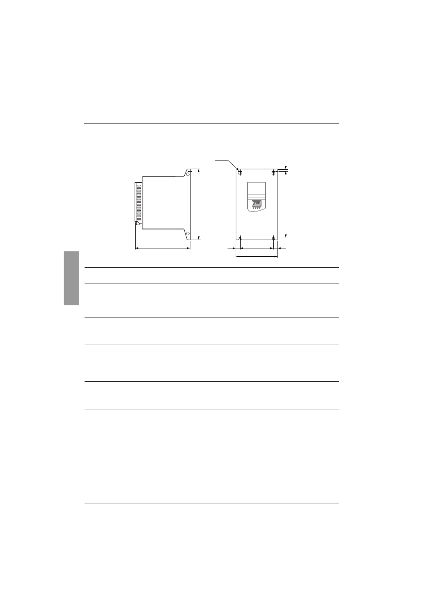
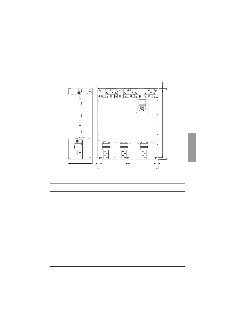
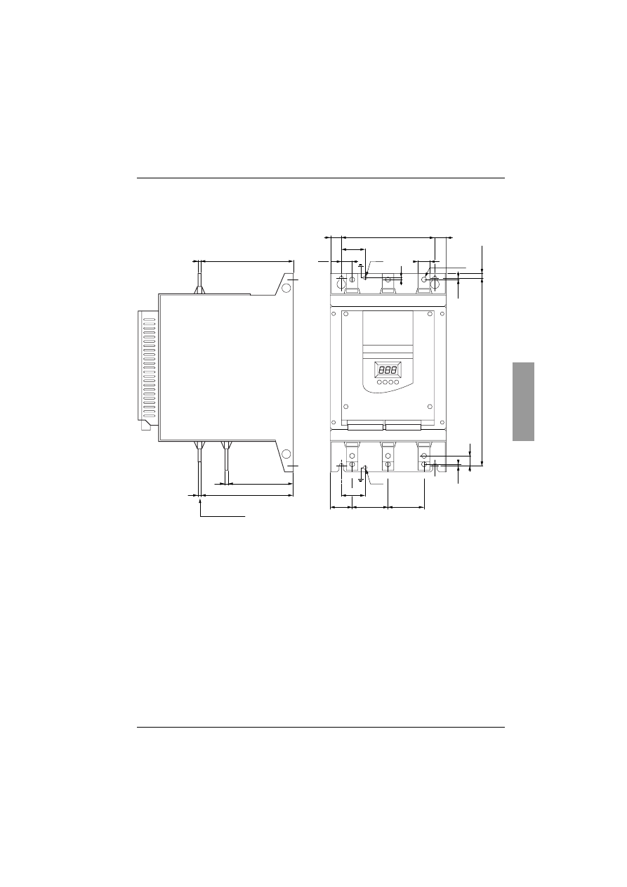
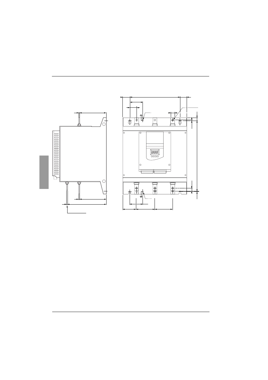
Dimensions
ATS 48D17 • …C66 •
ATS 48
a
mm
b
mm
c
mm
e
mm
G
mm
H
mm
Ø
mm
Weight
kg
D17Q, D17Y
D22Q, D22Y
D32Q, D32Y
D38Q, D38Y
D47Q, D47Y
160
275
190
6.6
100
260
7
4.9
D62Q, D62Y
D75Q, D75Y
D88Q, D88Y
C11Q, C11Y
190
290
235
10
150
270
7
8.3
C14Q, C14Y
C17Q, C17Y
200
340
265
10
160
320
7
12.4
C21Q, C21Y
C25Q, C25Y
C32Q, C32Y
320
380
265
15
250
350
9
18.2
C41Q, C41Y
C48Q, C48Y
C59Q, C59Y
C66Q, C66Y
400
670
300
20
300
610
9
51.4
e
G
=
=
a
H
c
4 x ¯
b
101
ENGLISH
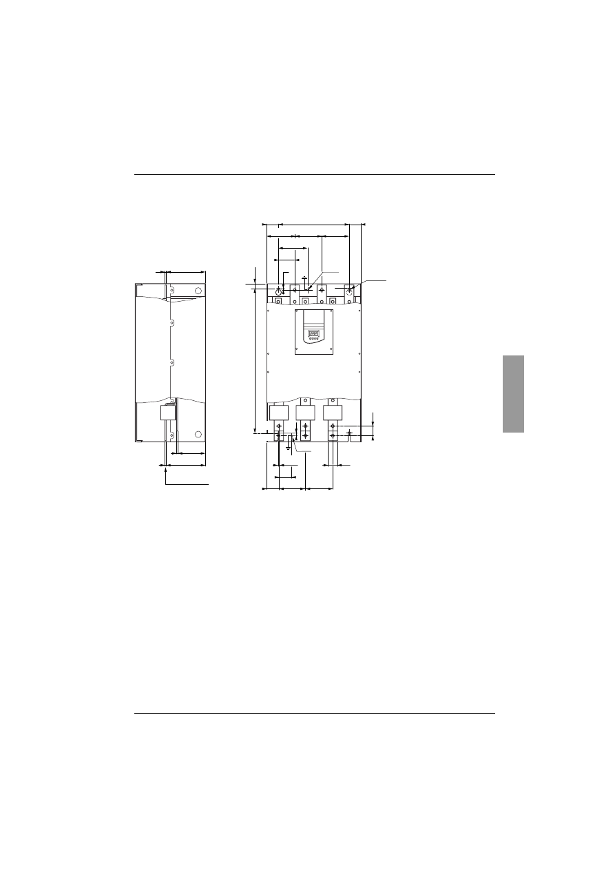
Dimensions
ATS 48C79 • …M12 •
ATS 48
a
mm
b
mm
c
mm
e
mm
G
mm
H
mm
Ø
mm
Weight
kg
C79Q, C79Y
M10Q, M10Y
M12Q, M12Y
770
890
315
20
350
850
9
115
G
G
=
=
c
a
6 x ¯
b
He
ENGLISH
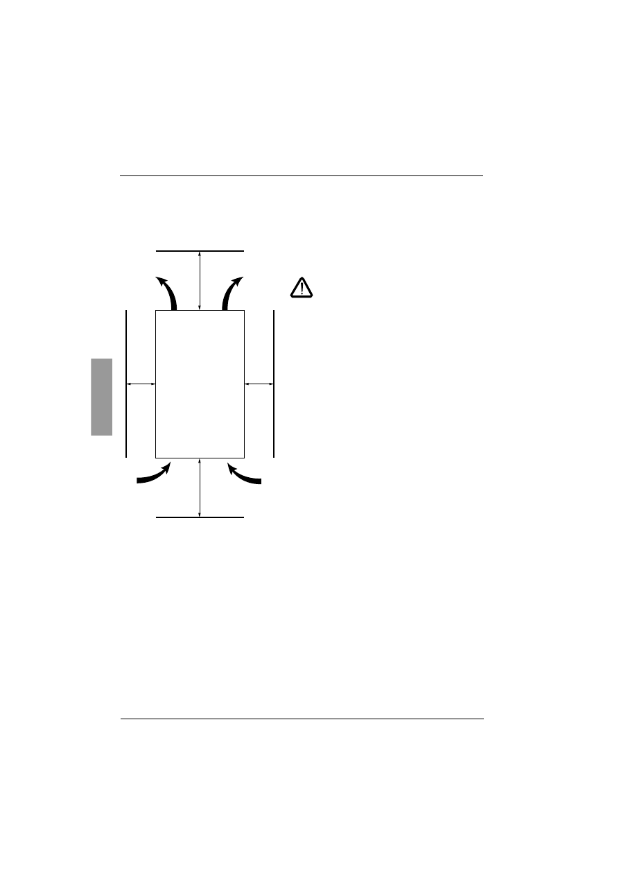
102
Mounting recommendations
Install the unit vertically, at ± 10°.
Do not install the unit close to, especially above, heating elements.
Leave sufficient free space to ensure that the air required for cooling purposes can circulate from the bottom
to the top of the unit.
Check that no liquids, dust or conductive
objects can fall into the starter (degree of
protection IP00 from above)
Starter ventilation
On starters fitted with a cooling fan, the fan is switched on automatically as soon as the heatsink temperature
reaches 50°C. It is switched off when the temperature falls back to 40°C.
Fan flow rate:
ATS 48 D32 • and D38 • : 14 m
3
/hour
ATS 48 D47 •
: 28 m
3
/hour
ATS 48 D62 • to C11 • : 86 m
3
/hour
ATS 48 C14 • and C17 • : 138 m
3
/hour
ATS 48 C21 • to C32 • : 280 m
3
/hour
ATS 48 C41 • to C66 • : 600 m
3
/hour
ATS 48 C79 • to M12 • : 1,200 m
3
/hour
≥
100 mm
≥
50 mm
≥
50 mm
≥
100 mm
103
ENGLISH
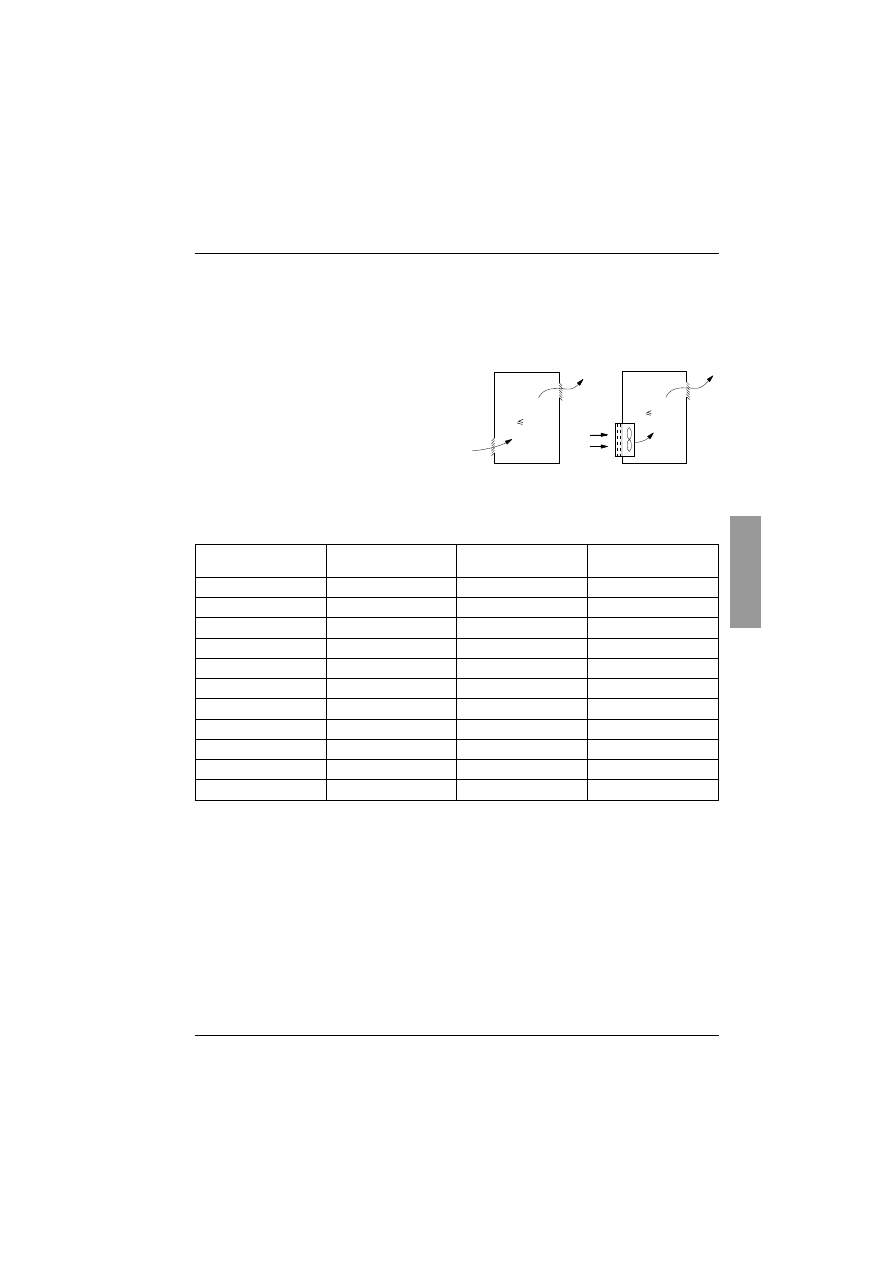
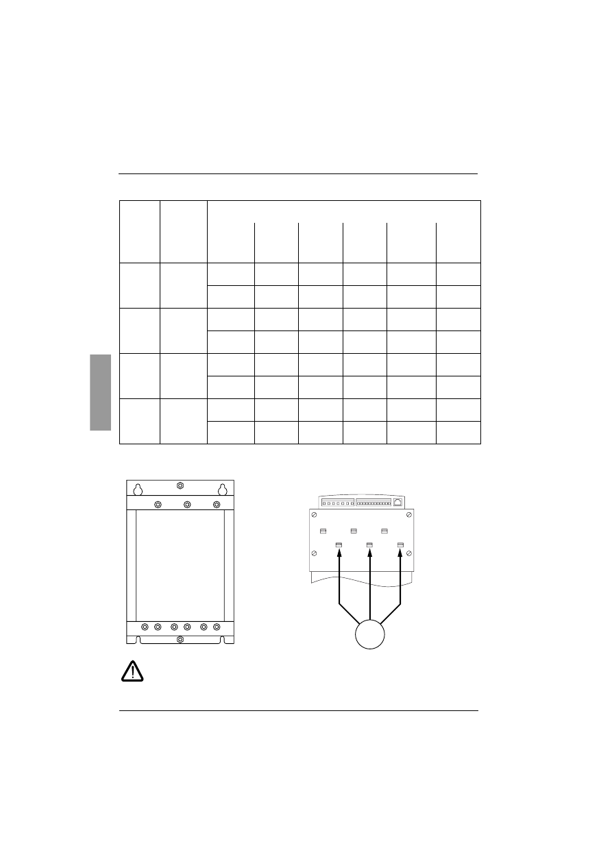
Mounting in a wall-fixing or floor-standing enclosure
Metal wall-fixing or floor-standing enclosure with IP 23 degree
of protection
Observe the mounting recommendations on the previous page.
To ensure proper air circulation in the drive:
- Fit ventilation grilles.
- Ensure that ventilation is adequate: if not install
a forced ventilation unit, with a filter if necessary.
Power dissipated by the starters, not bypassed, at their
nominal current
Note: When the starters are bypassed the amount of power dissipated is extremely small (between 15
and 30 W)
Control consumption (all ratings)
: 25 W non-ventilated
ATS48D32 to C17 Q/Y
: 30 W ventilated
ATS48C21 to D32 Q/Y
: 50 W ventilated
ATS48C41 to M12 Q/Y
: 80 W ventilated
Starter reference
ATS 48
Power in W
Starter reference
ATS 48
Power in W
D17Q, D17Y
59
C21Q, C21Y
580
D22Q, D22Y
74
C25Q, C25Y
695
D32Q, D32Y
104
C32Q, C32Y
902
D38Q, D38Y
116
C41Q, C41Y
1339
D47Q, D47Y
142
C48Q, C48Y
1386
D62Q, D62Y
201
C59Q, C59Y
1731
D75Q, D75Y
245
C66Q, C66Y
1958
D88Q, D88Y
290
C79Q, C79Y
2537
C11Q, C11Y
322
M10Q, M10Y
2865
C14Q, C14Y
391
M12Q, M12Y
3497
C17Q, C17Y
479
G¡ 40¡C
θ°
40
°
C
ENGLISH
104
Power terminals
Layout of the power terminals, ATS 48D17 • to C11 •
Motor to be connected to 2/T1, 4/T2, 6/T3
Terminals
Functions
Maximum connection capacity
Terminal tightening torque
ATS 48
D17 • D22 •
D32 • D38 •
D47 •
ATS 48
D62 • D75 •
D88 • C11 •
ATS 48
C14 • C17 •
ATS 48
C21 • C25 •
C32 •
ATS 48
C41 • C48 •
C59 • C66 •
ATS 48
C79 • M10 •
M12 •
s
Earth
connections
connected
to earth
10 mm
2
1.7 N.m
16 mm
2
3 N.m
120 mm
2
27 N.m
120 mm
2
27 N.m
240 mm
2
27 N.m
2x240 mm
2
27 N.m
8 AWG
15 lb.in
4 AWG
26 lb.in
Busbar
238 lb.in
Busbar
238 lb.in
Busbar
238 lb.in
Busbar
238 lb.in
1/L1
3/L2
5/L3
Power
supply
16 mm
2
3 N.m
50 mm
2
10 N.m
95 mm
2
34 N.m
240 mm
2
34 N.m
2x240 mm
2
57 N.m
4x240 mm
2
57 N.m
8 AWG
26 lb.in
2/0 AWG
88 lb.in
2/0 AWG
300 lb.in
Busbar
300 lb.in
Busbar
500 lb.in
Busbar
500 lb.in
2/T1
4/T2
6/T3
Outputs to
motor
16 mm
2
3 N.m
50 mm
2
10 N.m
95 mm
2
34 N.m
240 mm
2
34 N.m
2x240 mm
2
57 N.m
4x240 mm
2
57 N.m
8 AWG
26 lb.in
2/0 AWG
88 lb.in
2/0 AWG
300 lb.in
Busbar
300 lb.in
Busbar
500 lb.in
Busbar
500 lb.in
A2
B2
C2
Starter
bypass
16 mm
2
3 N.m
50 mm
2
10 N.m
95 mm
2
34 N.m
240 mm
2
34 N.m
2x240 mm
2
57 N.m
4x240 mm
2
57 N.m
8 AWG
26 lb.in
2/0 AWG
88 lb.in
2/0 AWG
300 lb.in
Busbar
300 lb.in
Busbar
500 lb.in
Busbar
500 lb.in
1/L1
A2 2/T1
B2 4/T2
C2 6/T3
3/L2
s
s
5/L3
M
A2
2/T1
B2
4/T2
C2
6/T3
105
ENGLISH
Power terminals
Layout of the power terminals, ATS 48C14 • and C17 •
18
M6
20
2
40
38
62
62
159
motor
5
116.5
5
162
5
40
1/L1
3/L2
5/L3
A2
B2
C2
2/T1
4/T2
6/T3
160
=
=
1
14
1
10
320
M6
9xØ9
ENGLISH
106
Power terminals
Layout of the power terminals,
ATS 48C21 • to C32 •
2
66
70
90
90
18
2
15
350
35
M10
20
136.5
5
136.5
5
196.5
5
66
1/L1
3/L2
5/L3
A2
B2
C2
4/T2
2/T1
6/T3
250
=
=
9xØ12
motor
M10
107
ENGLISH
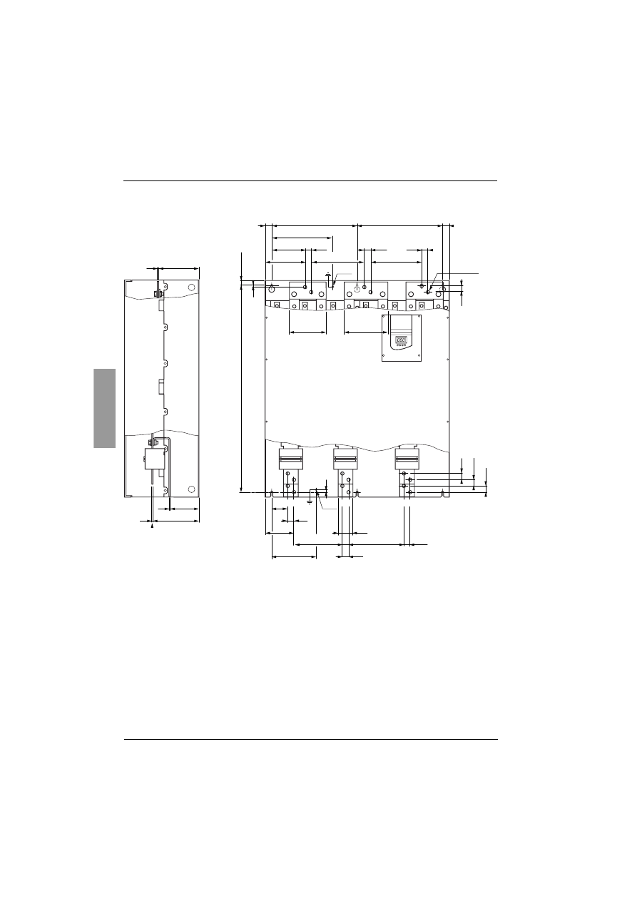
Power terminals
Layout of the power terminals, ATS 48C41 • to C66 •
0,25
40
165
216
5
5
58
115
115
50
M10
300
=
=
120
20
115
115
69
5
127
40
15
610
165
5
1/L1
3/L2 5/L3
B2
C2
4/T2
6/T3
9xØ14
2/T1
A2
M10
motor
ENGLISH
108
Power terminals
Layout of the power terminals, ATS 48C79 • to M12 •
188
60
60
116.5
5
5
196.5
229
95
204
26
26
26
26
26
850
20
2
24
5
170
5
350
=
=
350
257
164
223.5
209.5
129
26
26
26
26
155
180
1/L1
3/L2
5/L3
A2
B2
C2
2/T1
4/T2
6/T3
18xØ14
motor
M10
M10

109
ENGLISH
Control terminals
The control terminals are fitted with one way plug-in connectors.
In order to access the control terminals on ATS 48C17 • to M12 • starters, the protective cover must be removed.
Electrical characteristics
Layout of control terminals
Maximum connection capacity
: 2.5 mm2 (12 AWG)
Maximum tightening torque
: 0.4 N.m (3.5 lb.in)
Terminals
Function
Characteristics
CL1
CL2
Altistart control power supply
ATS 48 •••Q: 220 to 400 V + 10% - 15%, 50/60 Hz
ATS 48 • • • Y: 110 to 230 V + 10% - 15%, 50/60 Hz
Consumption see page 103.
R1A
R1C
Normally open (N/O) contact of
programmable relay r1
Min. switching capacity
• 10 mA for 6 V
a
Max. switching capacity on inductive load (cos
ϕ
= 0.5
and L/R = 20 ms):
• 1.8 A for 230 V
c
and 30 V
a
Max. voltage 400 V
R2A
R2C
Normally open (N/O) contact of end
of starting relay r2
R3A
R3C
Normally open (N/O) contact of
programmable relay r3
STOP
RUN
LI3
LI4
Stop starter (state 0 = stop)
Run starter (state 1 = run if STOP is
at 1)
Programmable input
Programmable input
4 x 24 V logic inputs with 4.3 k
Ω
impedance
Umax = 30 V, Imax = 8 mA
state 1: U > 11 V - I > 5 mA
state 0: U < 5 V - I < 2 mA
24V
Logic input power supply
+24 V ± 25% isolated and protected against short-
circuits and overloads, maximum current: 200 mA
LO+
Logic output power supply
To be connected to 24 V or an external source
LO1
LO2
Programmable logic outputs
2 open collector outputs, compatible with level 1 PLC,
IEC 65A-68 standard.
• Power supply +24 V (min. 12 V, max. 30 V)
• Max. current 200 mA per output with an external
source
AO1
Programmable analog output
Output can be configured as 0 - 20 mA or 4 - 20 mA
• accuracy ± 5% of the max. value, max. load
impedance 500
Ω
COM
I/O common
0 V
PTC1
PTC2
Input for PTC probes
Total resistance of probe circuit 750
Ω
at 25°C
(3 x 250
Ω
probes in series, for example)
(RJ 45)
Connector for
• remote terminal
• PowerSuite
• communication bus
RS 485 Modbus
CL1
CL2
R1A
R1C
R2A
R2C
R3A
R3C
STOP
RUN
LI3
LI4
24V
LO+
LO1
LO2
AO1
COM
PTC1
PTC2
(RJ 45)

ENGLISH
110
Wiring/RUN - STOP commands
Wiring recommendations
Power
Observe the cable cross-sectional areas recommended in the standards.
The starter must be earthed to conform to the regulations concerning leakage currents. When the use of an
upstream "residual current device" for protection is required by the installation standards, an A-Si type device
must be used (to avoid accidental tripping during power up). Check its compatibility with the other protective
devices. If the installation involves several starters on the same line, each starter must be earthed separately.
If necessary, fit a line choke (consult the catalogue).
Keep the power cables separate from circuits in the installation with low-level signals (detectors, PLCs,
measuring apparatus, video, telephone).
Control
Keep the control circuits away from the power cables.
Functions of the RUN and STOP logic inputs
(See application diagram see
page 112
)
2-wire control
Run and stop are controlled by state 1 (run) or 0 (stop), which is taken into account at the same time on the
RUN and STOP inputs.
On power-up or a manual fault reset the motor will restart if the RUN command is present.
3-wire control
Run and stop are controlled by 2 different logic inputs.
A stop is obtained on opening (state 0) the STOP input.
The pulse on the RUN input is stored until the stop input opens.
On power-up or a manual fault reset or after a stop command, the motor can only be powered once the RUN
input has been opened (state 0) followed by a new pulse (state 1).
111
ENGLISH
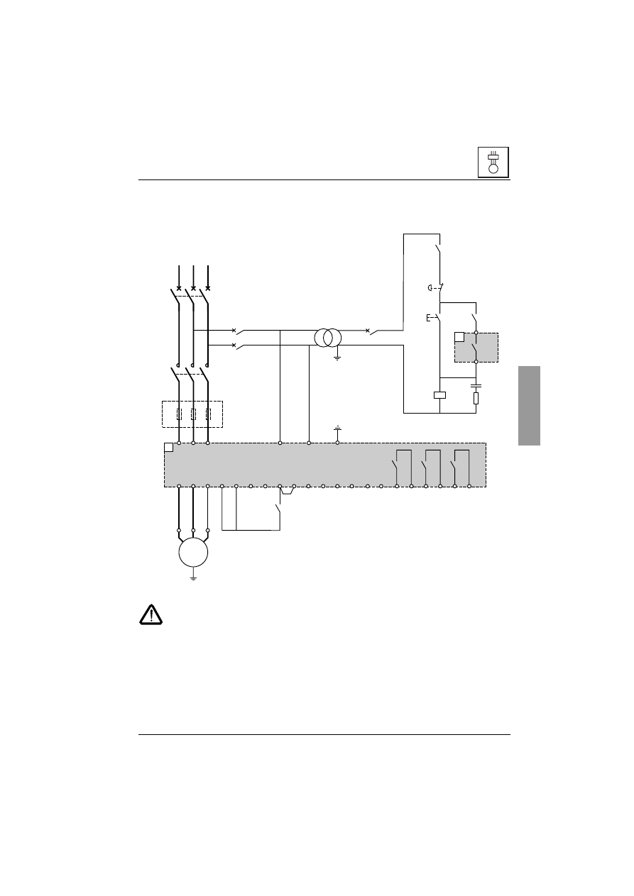
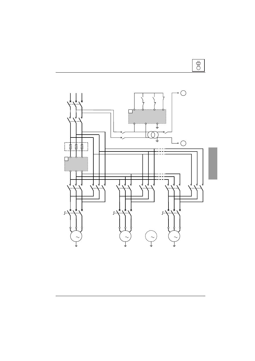
Application diagram
ATS 48: Non-reversing, with line contactor, freewheel stop, type 1
coordination
(1) Installation of fast-acting fuses for type 2 coordination (conforming to IEC 60 947-4-2)
(2) Assignment of relay R1: isolating relay (rII). See “Electrical characteristics”, page 109. Beware
of the operating limits of the contact, for example when connecting to high rating contactors.
(3) Insert a transformer if the supply voltage is different to that permitted by the ATS 48 control. See
“Electrical characteristics”, page 109.
M
2/T1
4/T2
6/T3
STOP
RUN
LI3
+24V
LO+
LO1
LO2
COM
AO1
R1A
R1C
R2A
R2C
R3A
R3C
3/L2
1/L1
5/L3
CL2
2
4
6
– KM1
1
2
3
4
5
6
M1
3
c
U1
W1
V1
– T1
R1A
(2)
R1C
13
14
– Q1
13
14
– KM1
– S1
– S2
– KM1
A1
A2
A1
A1
– KM1
Q3
(1)
54
53
1
2
1
2
1
2
– Q1
1
3
5
CL1
LI4
PTC1
PTC2
(3)
stop
Emergency
ENGLISH
112
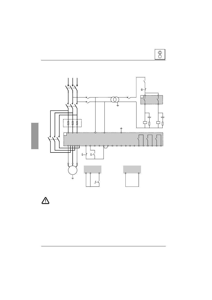
Application diagram
ATS 48: Non-reversing with line contactor, bypass, freewheel or controlled
stop, type 1 coordination
(1) Installation of fast-acting fuses for type 2 coordination (conforming to IEC 60 947-4-2)
(2) Assignment of relay R1: isolating relay (rII). Beware of the operating limits of the contact, for
example when connecting to high rating contactors. See “Electrical characteristics”, page 109.
(3) Beware of the operating limits of the contact, for example when connecting to high rating
contactors. See “Electrical characteristics”, page 109.
(4) Insert a transformer if the supply voltage is different to that permitted by the ATS 48 control. See
“Electrical characteristics”, page 109.
(5) See “2-wire control”, page 110.
(6) See “3-wire control”, page 110.
M
2/T1
4/T2
A2
B2
C2
6/T3
STOP
RUN
LI3
LI4
+24V
LO1
LO2
COM
AO1
R1A
R1C
R2A
R2C
R3A
R3C
3/L2
1/L1
5/L3
CL1
CL2
2
4
6
– KM1
1
2
3
4
5
6
M1
3
c
U1
W1
V1
– T1
PTC1
PTC2
R2A
R2C
R1A
R1C
13
14
– Q1
– KM3
1
2
3
4
5
6
– KM3
A1
A2
– KM1
A1
A2
A1
A1
S1
+24V
STOP
RUN
LO+
(1)
S2
Q3
S1
STOP
1
2
1
2
1
2
+24V
– Q1
1
3
5
(4)
(2)
(3)
Emergency
stop
3-wire control (6)
2-wire control (5)
PC or PLC control
113
ENGLISH
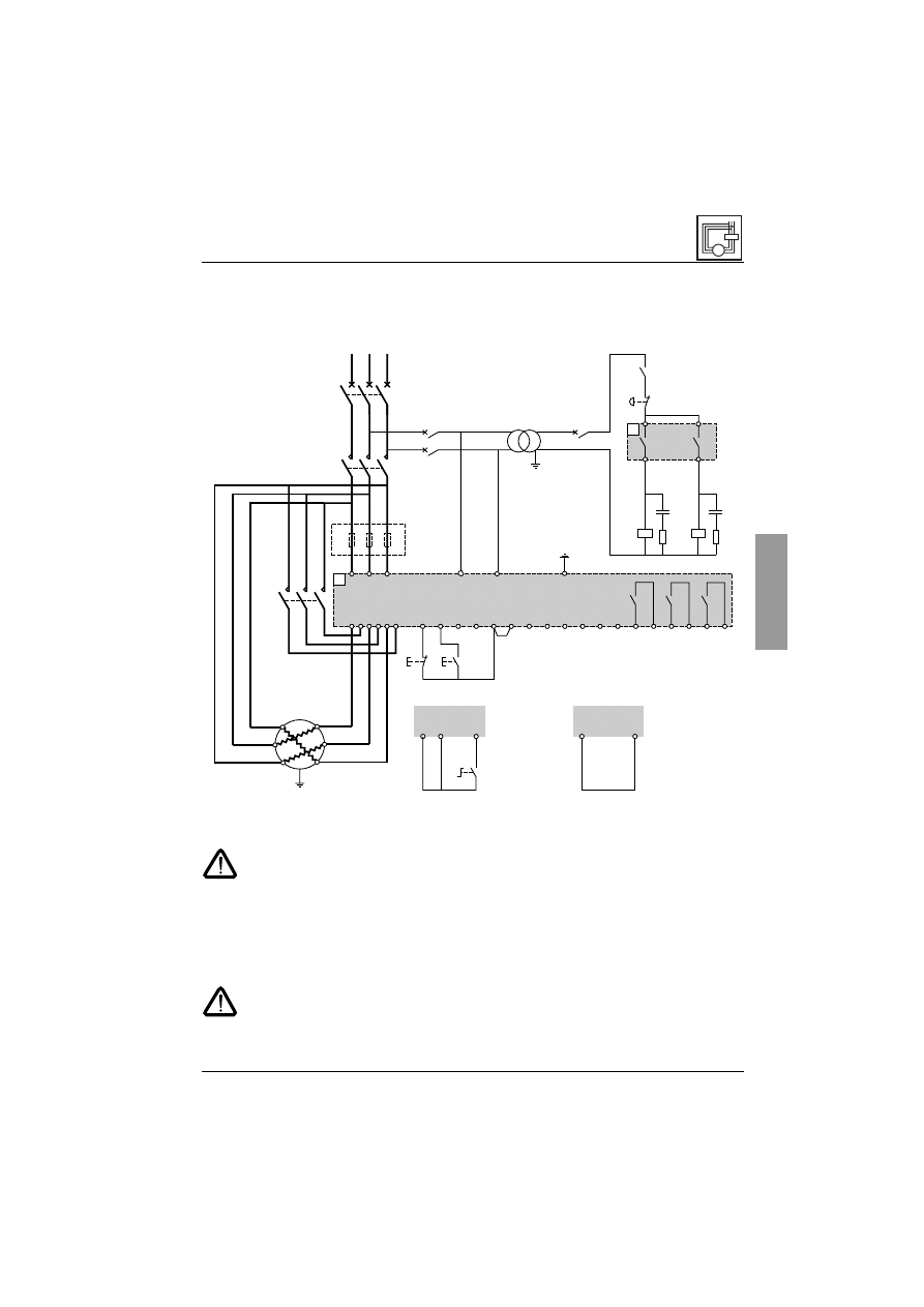
Application diagram
ATS 48: Non-reversing, freewheel or controlled stop, type 1 coordination,
with line contactor, bypass, connection to delta in the motor, ATS 48•••Q
only
(1) Installation of fast-acting fuses for type 2 coordination (conforming to IEC 60 947-4-2).
(2) It is mandatory to use KM1. External differential thermal protection will need to be added.
(3) Assignment of relay R1: isolating relay (rII). Beware of the operating limits of the contact, for
example when connecting to high rating contactors. See “Electrical characteristics”, page 109.
(4) Beware of the operating limits of the contact, for example when connecting to high rating
contactors. See “Electrical characteristics”, page 109.
(5) Insert a transformer if the supply voltage is different to that permissible by the ATS 48 control.
See “Electrical characteristics”, page 109.
(6) See “2-wire control”, page 110.
(7) See “3-wire control”, page 110.
If the bypass contactor is used, "PHF" fault detection can be extended.
M
2/T1
4/T2
A2
B2
C2
6/T3
STOP
RUN
LI3
LI4
+24V
LO1
LO2
COM
AO1
R1A
R1C
R2A
R2C
R3A
R3C
3/L2
1/L1
5/L3
CL1
CL2
2
4
6
– KM1
1
2
3
4
5
6
PTC1
PTC2
– KM3
1
2
3
4
5
6
A1
S1
+24V
STOP
RUN
LO+
(1)
(3)
S2
Q3
S1
STOP
1
2
1
2
+24V
– Q1
1
3
5
– T1
R2A
R2C
R1A
R1C
13
14
– Q1
– KM3
A1
A2
– KM1
A1
A2
A1
1
2
(4)
(5)
(2)
U1
W1
V1
V2
W2
U2
2-wire control (6)
PC or PLC control
3-wire control (7)
Emergency
stop
ENGLISH
114
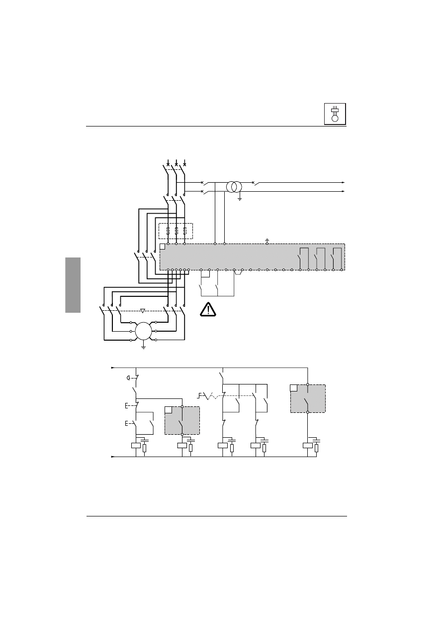
Application diagram
ATS 48: Non-reversing, freewheel or controlled stop, line contactor, motor
bypass, LSP/HSP with two sets of parameters
(4) Beware of the operating limits of the contact, for example when connecting to high rating contactors. See
“Electrical characteristics”, page 109.
(5) Assignment of relay R1: isolating relay (rII). Beware of the operating limits of the contact, for example when
connecting to high rating contactors. See “Electrical characteristics”, page 109.
LI3 = LIS (second set of motor parameters)
S3: 1 = LSP, 2 = HSP
M
RUN
STOP
LI3
LI4
+24V
LO1
LO2
COM
AO1
R1A
R1C
R2A
R2C
R3A
R3C
PTC1
PTC2
LO+
2/T1
4/T2
A2
B2
C2
6/T3
3/L2
1/L1
5/L3
CL1
2
4
6
Ð KM1
1
2
3
4
5
6
CL2
Ð KM3
1
2
3
4
5
6
Ð KM2
Ð KM5
A1
Q3
1
2
1
2
Ð Q1
1
3
5
Ð T1
0
220
1
2
KA1
KM2
(1)
(2)
M1
3
c
U1
W1
V1
W2
U2
V2
(3)
(1) Installation of fast-acting fuses in the case
of type 2 coordination (conforming to IEC
60 947-4-2).
(2) Insert a transformer if the supply voltage is different to
that permitted by the ATS 48 control. See “Electrical
characteristics”, page 109.
(3) Ensure that the directions of motor rotation correspond
for both speeds.
KA1
KM1
KM5
KM2
KM5
KA1
S2
S1
KM2
KM2
KM1
KM5
Q1
220
0
A1
R1C
R1A
KM3
A1
R2C
R2A
KA1
S3
2
1
(5)
(4)
Emergency
stop
115
ENGLISH
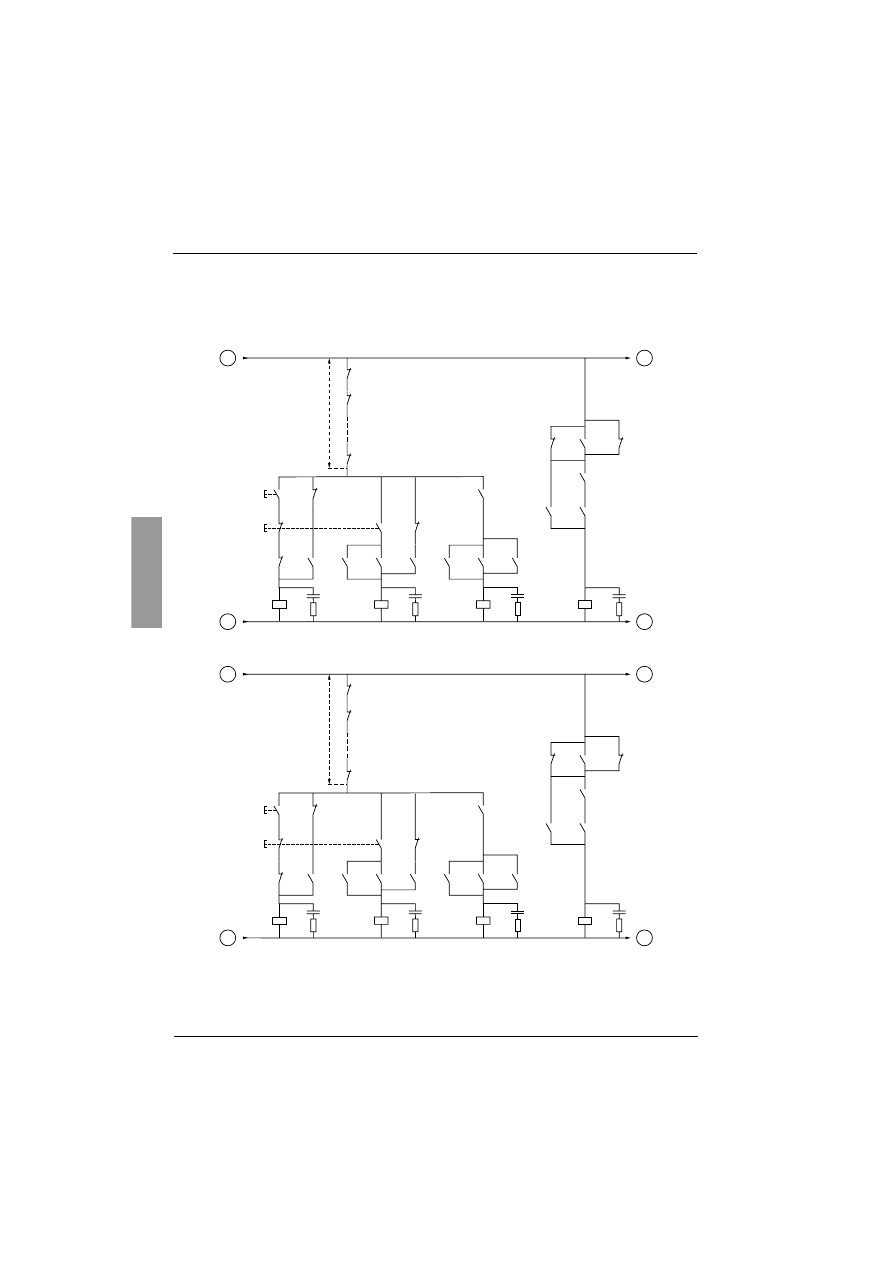
Application diagram
ATS 48: Non-reversing with line contactor, starting and deceleration of
several cascaded motors with a single Altistart
(1) Installation of fuses for type 2 coordination (conforming to IEC 60 947-4-2)
(2) Insert a transformer if the supply voltage is different to that permitted by the ATS 48 control. See “Electrical
characteristics”, page 109.
Important:
• A "cascading" logic input must be configured on the ATS48 (LI3 = LIC). See “Activation of the cascade
function”, page 140.
• In the event of a fault it will not be possible to decelerate or brake any motors that may be running at that
time.
• Adjust the thermal protection of each circuit breaker QN1 to the nominal motor current.
M
– KM11
1
2
3
4
5
6
– KM12
1
2
3
4
5
6
– KM1
1
2
3
4
5
6
1/L1
3/L2
5/L3
2/T1
4/T2
6/T3
A1
– T1
2
4
6
1
– Q11
3
5
U1
W1
V1
M1
3
– KM21
1
2
3
4
5
6
– KM22
1
2
3
4
5
6
2
4
6
1
– Q21
3
5
U2
W2
V2
M2
3
– KMn1
1
2
3
4
5
6
– KMn2
1
2
3
4
5
6
2
4
6
1
– Qn1
3
5
Un
Wn
Vn
Mn
3
Mi
3
2
4
6
1
2
1
2
1
2
CL1
CL2
A1
RUN
+24V
KAT
LI3
STOP
KALIT
KALIT
A
KA
KALI
B
(1)
– Q3
– Q1
1
3
5
(2)
Motor 2
Motor n
Motor i
Motor 1
ENGLISH
116
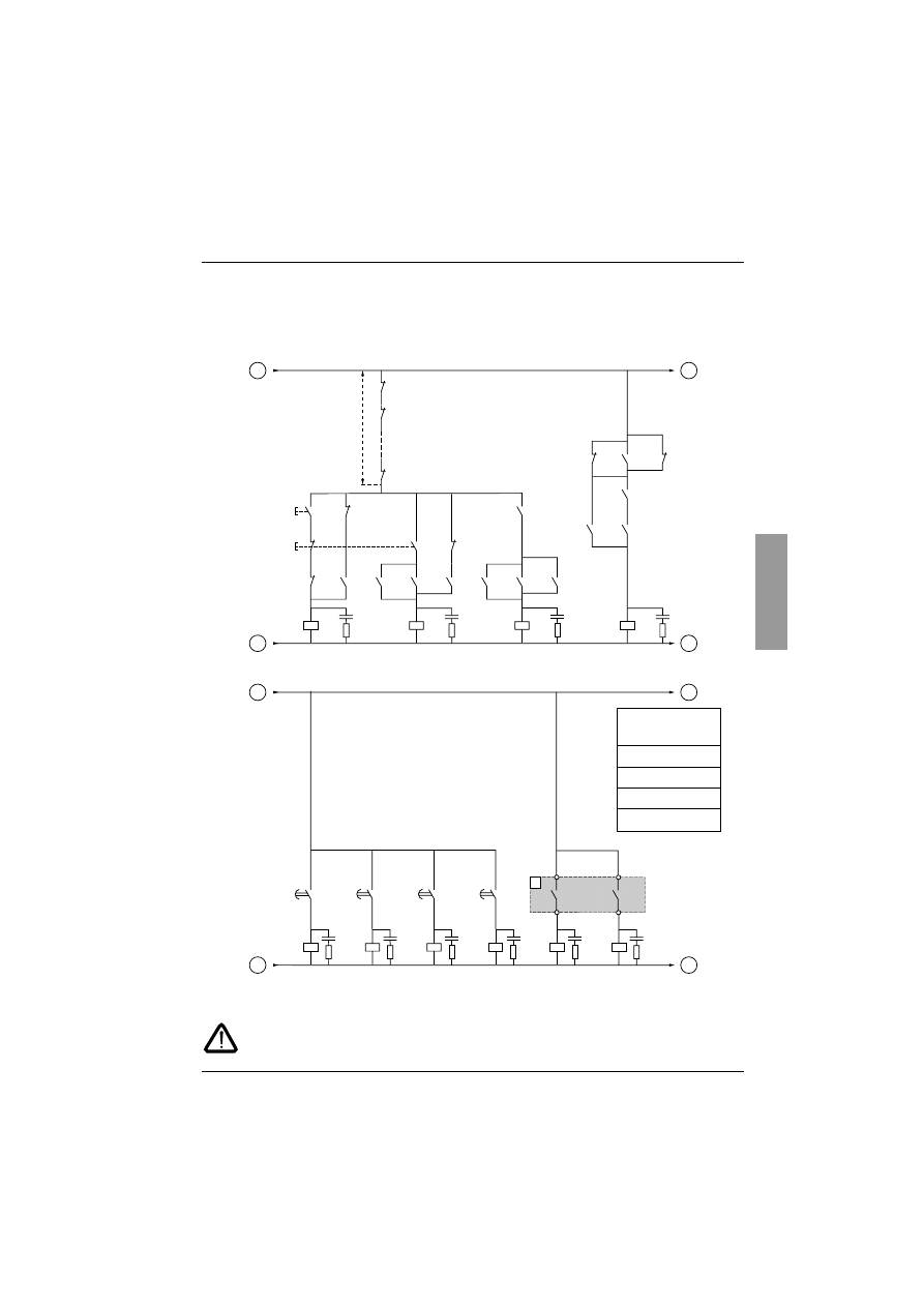
Application diagram
ATS 48: Non-reversing with line contactor, starting and deceleration of
several cascaded motors with a single Altistart
Motor 1 control
Motor 2 control
BPM1: "Run" button motor 1
BPA1: "Stop" button motor 1
BPM2: "Run" button motor 2
BPA2: "Stop" button motor 2
KAM1
AR1
KM11
KM12
KM12
KT
SHUNT
SHUNT
KAT
ACDEC
BPM1
BPA1
BPA1
KAM1
KM11
KAM1
KM11
KM11
KM12
KM12
AR1
AR1
AR1
ART
B
A
D
C
KM21
KMi1
KMn1
(n-1) contacts
KAM2
AR2
KM21
KM22
KM22
KT
SHUNT
SHUNT
KAT
ACDEC
BPM2
BPA2
BPA2
KAM2
KM21
KAM2
KM21
KM21
KM22
KM22
AR2
AR2
AR2
ART
D
C
F
E
KM11
KMi1
KMn1
(n-1) contacts
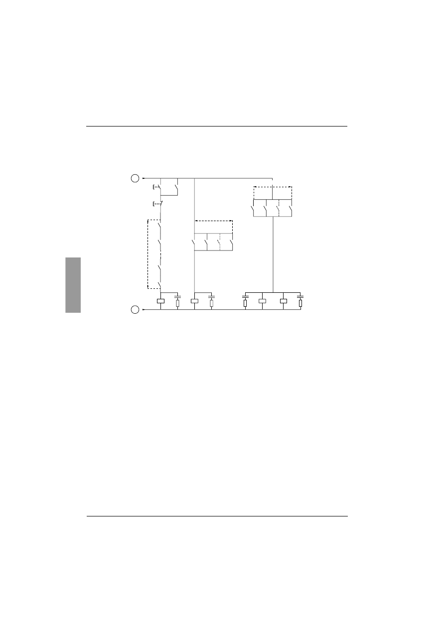
117
ENGLISH
Application diagram
ATS 48: Non-reversing with line contactor, starting and deceleration of
several cascaded motors with a single Altistart
Motor n control
Cascade control
Wait for the end of the timer KALIT between 2 consecutive stop requests
BPMn: "Run" button motor n
R1 must be configured as an isolating relay (r1 = rII)
BPAn: "Stop" button motor n
KAMn
ARn
KMn1
KMn2
KMn2
KT
SHUNT
SHUNT
KAT
ACDEC
BPMn
BPAn
BPAn
KAMn
KMn1
KAMn
KMn1
KMn1
KMn2
KMn2
ARn
ARn
ARn
ART
F
E
H
G
KM11
KM21
KMi1
(n-1) contacts
KAT
KT
KA
K
KALI
KALIT
KALIT
ART
ACDEC
SHUNT
H
G
J
I
A1
R2C
ATS 48
R2A
R1C
R1A
Time delay
settings
1 s > KA > 0.1 s
K > 0.2 s
KALI > K
KALIT > 0.1 s
ENGLISH
118
Application diagram
ATS 48: Non-reversing with line contactor, starting and deceleration of
several cascaded motors with a single Altistart
Cascade control
MST: General "Run" button
MHT: General "Stop" button
KM1
KA
K
KALI
KM1
MST
MHT
Qn1
Qi1
Q21
KAM1 KAM2 KAMi KAMn
AR2
AR1
ARi
ARn
Q11
J
I
n contacts
n contacts
n contacts

119
ENGLISH
Application diagram
ATS 48: Non-reversing with line contactor, starting and deceleration of
several cascaded motors with a single Altistart
Description of the complete sequence
Start with MST so that KM1 rises (line contactor)
1 - 2 - 3
Press BPM1 to start motor 1. Press BPM2 to start motor 2, press BPMn to start motor n.
When BPM1 is pressed, KAM1 rises, as does KM11 because ACDEC is activated (the ATS48 is powered by
MST and KM1).
KA rises because KAM1 is closed. KAT also rises after an adjustable time delay.
4 - 5
The ATS48 starts the motor following a run command on RUN with KA and KAT.
KAM1 drops out due to KAT.
KM11 remains closed.
6 - 7
At the end of starting, R2 on the ATS48 rises, SHUNT is closed, KM12 is closed by SHUNT and KM11 remains
closed.
8 - 9
After a short time R2 drops out followed by R1 (starter bypass function).
KM11 opens because ACDEC is open.
The motor continues to be powered by KM12.
The ATS48 displays a fault code.
Follow the same procedure to start the next motor. To start motor n use BPMn and to stop motor n use
BPAn. The motors can be started and stopped in any order.
To stop motor 1 press BPA1. AR1 closes
a - b - c - d
K and KALI are closed.
LI on the ATS48 receives a command from KALI and KALIT (LI must be adjusted to value LIC).
R1 and R2 on the ATS48 rise (a pulse on R2 and R1 remains closed until the motor has come to a complete
stop).
e
KM11 closes.
After an adjustable time delay, KT and KALIT rise.
f
The ATS48 receives a stop command from KALIT.
g
KM12 drops out.
The ATS48 decelerates the motor.
h
R1 on the ATS48 opens when the motor has come to a complete stop.
i
KM11 opens.
The ATS48 is ready to start or stop another motor.
ENGLISH
120
Application diagram
ATS 48: Non-reversing with line contactor, starting and deceleration of
several cascaded motors with a single Altistart
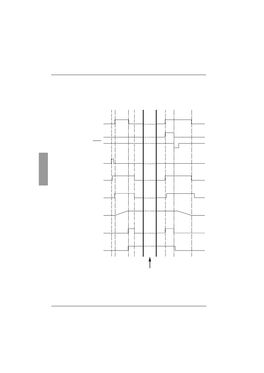
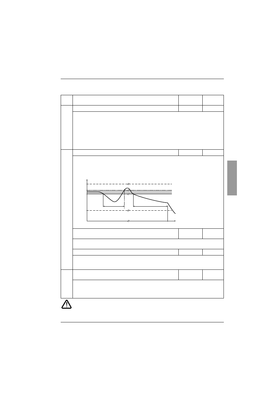
Trend diagram
4
8
c
a
f
b
e
d
g
h
h
i
h
3
1
2
5
6
9
7
Motor powered by the ATS48
LI3
STOP
RUN
RI
(Isolating relay)
KM11
Speed
R2
(Control of the
starter bypass contactor)
KM12
Motor start
Motor stop
ATS48 idle

121
ENGLISH
Thermal protection
Starter thermal protection
Thermal protection is provided by the PTC probe fitted on the heatsink and by calculating the temperature rise
of the thyristors.
Motor thermal protection
The starter continuously calculates the temperature rise of the motor based on the controlled nominal current
In and the actual current absorbed.
Temperature rises can be caused by a low or high overload with a long or short duration. The tripping curves
on the following pages are based on the relationship between the starting current Is and the (adjustable) motor
current In.
Standard IEC60947-4-2 defines the protection classes giving the starting capacities of the motor (warm or cold
start) without thermal faults. Different protection classes are given for a COLD state (corresponding to a
stabilised motor thermal state, switched off) and for a WARM state (corresponding to a stabilised motor
thermal state, at nominal power).
The starter is factory-set to protection class 10.
This protection class can be modified using the PrO menu.
The thermal protection displayed by the starter corresponds to the iron time constant.
- An overload alarm is activated if the motor exceeds its nominal temperature rise threshold (motor thermal
state = 110%).
- A thermal fault stops the motor if it exceeds the critical temperature rise threshold (motor thermal state =
125%).
In the event of a prolonged start, the starter can trip on a fault or thermal alarm even if the value displayed is
less than the trip value.
The thermal fault can be indicated by relay R1 if thermal protection has not been disabled.
After the motor has stopped or the starter has been switched off, the thermal state is calculated even if the
control circuit is not powered. The Altistart thermal control prevents the motor from restarting if the temperature
rise is too high.
If a special motor is used (flameproof, submersible, etc.) thermal protection should be provided by PTC probes.
ENGLISH
122
Thermal protection
Motor thermal protection
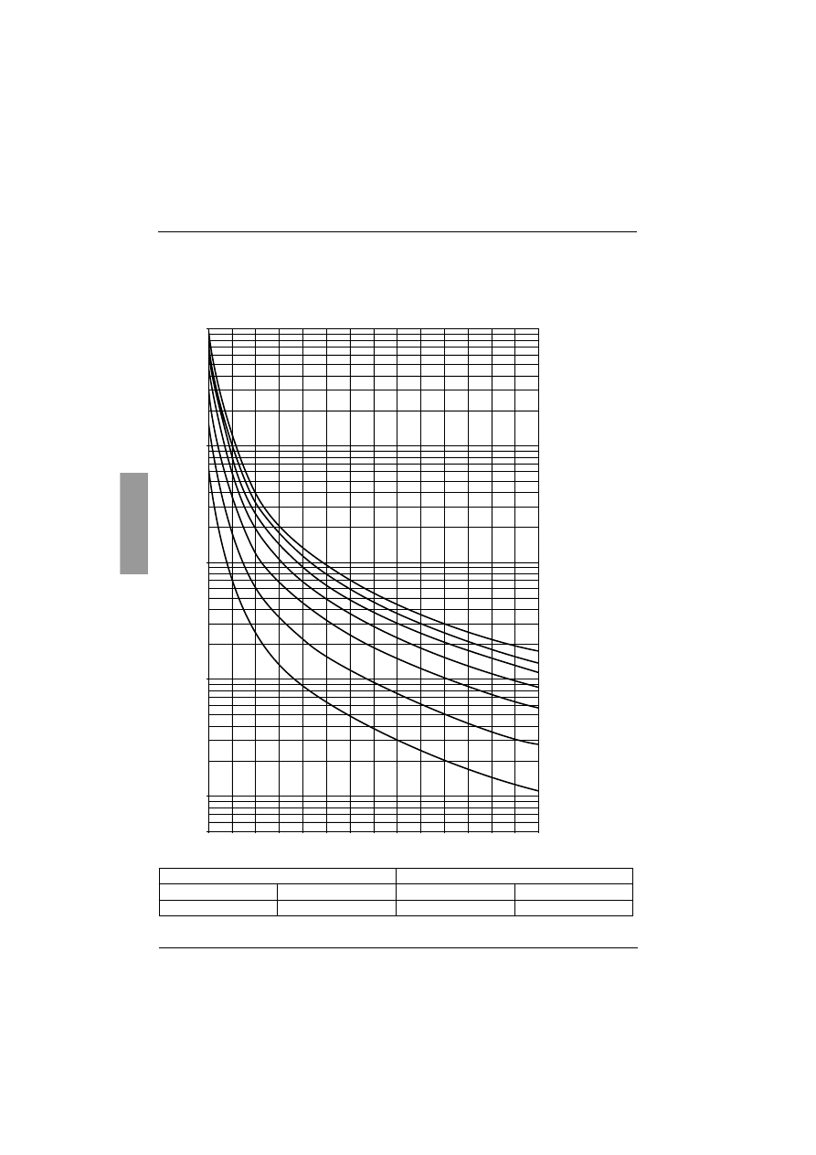
Cold curves
Trip time for a standard application (class 10)
Trip time for a severe application (class 20)
3 In
5 In
3.5 In
5 In
46 s
15 s
63 s
29 s
0.5
1
10
100
1000
10000
t(s)
8.00
I/Ie
7.50
7.00
6.50
6.00
5.50
5.00
4.50
4.00
3.50
3.00
2.50
2.00
1.5
1.12
Class 30
Class 10A
Class 2
Class 20
Class 15
Class 10
Class 25
123
ENGLISH
Thermal protection
Motor thermal protection
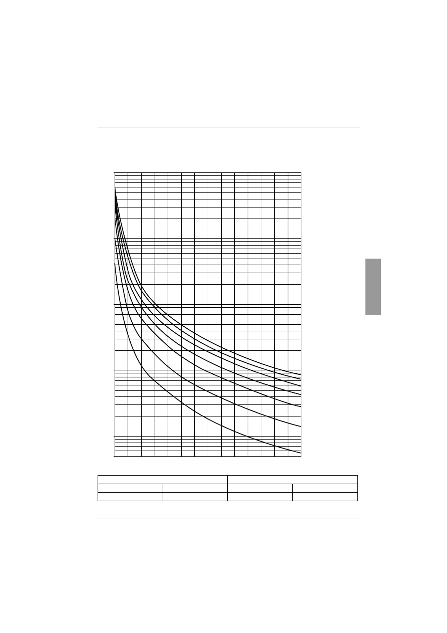
Warm curves
Trip time for a standard application (class 10)
Trip time for a severe application (class 20)
3 In
5 In
3.5 In
5 In
23 s
7.5 s
32 s
15 s
0.5
1
10
100
1000
10000
t(s)
8.00
I/Ie
7.50
7.00
6.50
6.00
5.50
5.00
4.50
4.00
3.50
3.00
2.50
2.00
1.5
1.12
Class 30
Class 25
Class 20
Class 15
Class 10
Class 10A
Class 2

ENGLISH
124
Thermal protection
Motor thermal protection with PTC probes
PTC probes integrated in the motor to measure its temperature can be connected to the control card terminals.
This analog value is managed by the starter.
The "PTC probe thermal overshoot" value can be processed and used in two ways:
- stop in the event of a fault if the signal is active
- activate an alarm if the signal is active. This alarm can be displayed in a starter status word (serial link)
or on a configurable logic output.
Note:
PTC probe protection does not deactivate the motor thermal protection provided by the calculation. Both types
of protection can operate in parallel.
125
ENGLISH
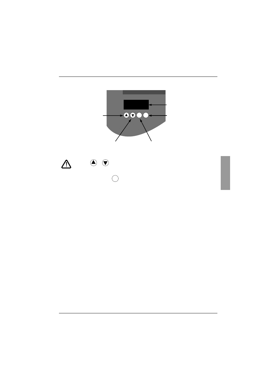
Display unit and programming
Functions of the keys and the display
Pressing
or
does not store the choices.
Store, save the displayed choice
:
The display flashes when a value is stored.
Display principle
The display principle for numbers differs depending on the maximum scale of the parameter and its value.
• Max. scale 9990:
- values 0.1 to 99.9 (examples: 05.5 = 5.5; 55.0 = 55; 55.5 = 55.5)
- values 100 to 999 (example: 555 = 555)
- values 1000 to 9990 (example: 5.55 = 5550)
• Max. scale 99900:
- values 1 to 999 (examples: 005 = 5; 055 = 55; 550 = 550)
- values 1000 to 9990 (example: 5.55 = 5550)
- values 10000 to 99900 (example: 55.5 = 55500)
Altistart 48
rdY
ESC
ENT
Te
DR
• 3 seven-segment
displays
• Enters a menu or a
parameter, or saves the
displayed parameter or
value
• Returns to the previous
menu or parameter, or
increases the displayed
value
• Exits a menu or parameter, or aborts the
displayed value to return to the previous value
in the memory
• Goes to the next menu or parameter, or
decreases the displayed value
ENT
ENGLISH
126
Display unit and programming
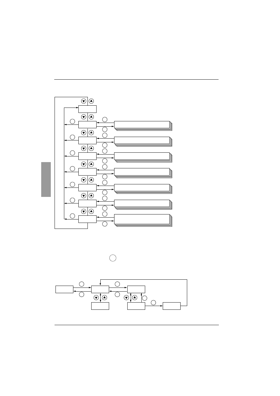
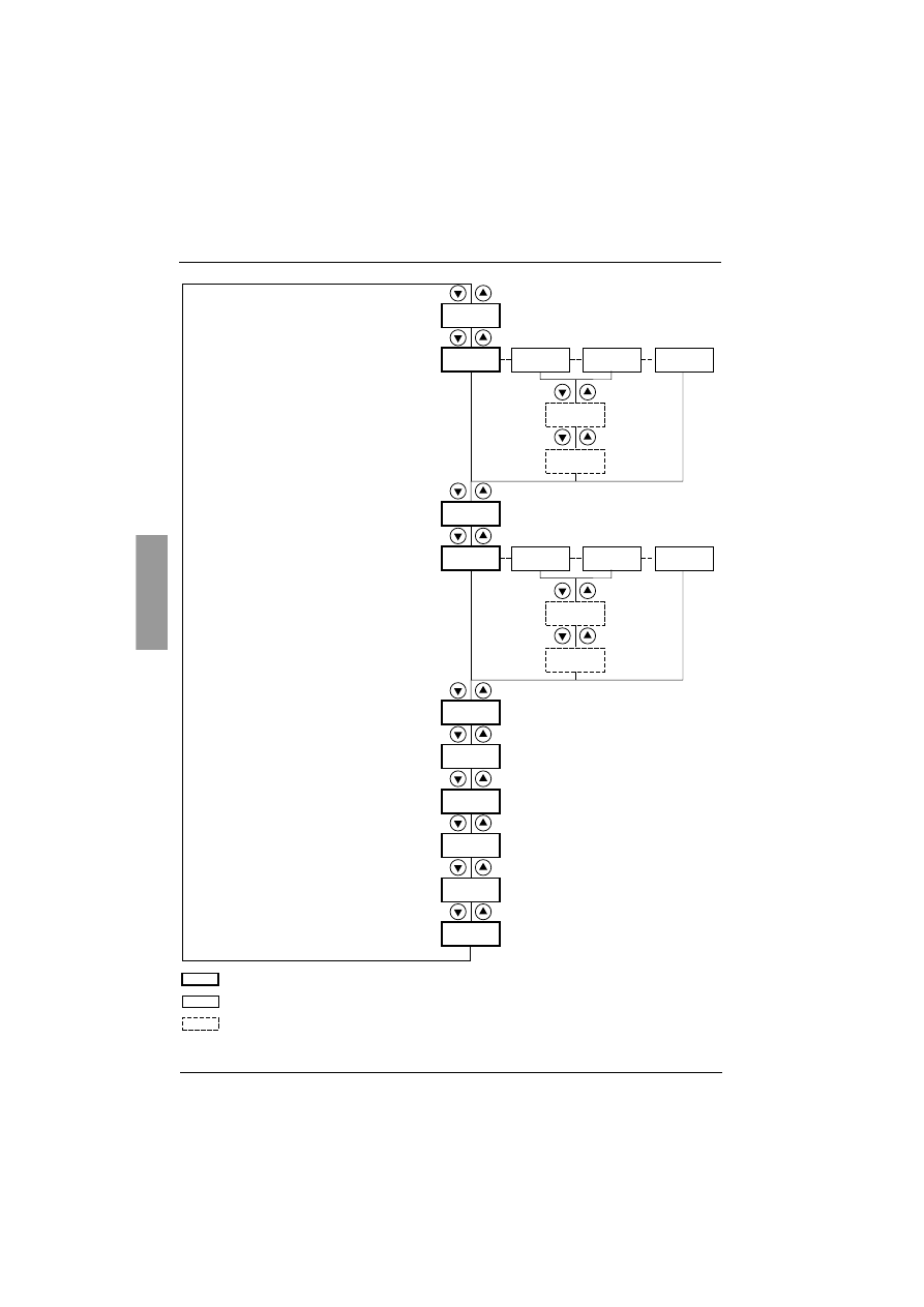
Accessing menus
(1) Management of the displayed value "XXX" is given in the table on the next page.
(2) Menu St2. is only visible if the "second set of motor parameters" function is configured.
Accessing parameters
Store, save the displayed choice
:
The display flashes when a value is stored.
Example:
XXX
(1)
SEt
PrO
drC
IO
St2
COP
SUP
ESC
ENT
ESC
ESC
ENT
ESC
ESC
ENT
ESC
ESC
ENT
ESC
ESC
ENT
ESC
ESC
ENT
ESC
ESC
ENT
ESC
Settings
Protection
Advanced settings
Assignment of the inputs/outputs
2nd motor parameters (2)
Communication
Display of starter status
Selection of the parameter
displayed and the locking code
ENT
SEt
ESC
ENT
ACC
ESC
ENT
015
tq0
026
026
ESC
ENT
Menu
Parameter
Value or assignment
Next parameter
1 flash
(save)
Browsing within
the menus

127
ENGLISH
Display unit and programming
Display of starter status
The displayed value "XXX" follows the following rules:
When current limiting is applied to the starter, the displayed value "XXX" flashes.
It is still possible to modify the parameters even if a fault occurs on the starter.
Value displayed
Condition
Fault code
Faulty starter
nLP
rdY
Starter without run command and:
• Power not supplied
• Power supplied
tbS
Starting time delay not elapsed
HEA
Motor heating in progress
Monitoring parameter selected by the user
(SUP menu). Factory setting: motor current
Starter with run command
brL
Starter braking
Stb
Waiting for a command (RUN or STOP) in cascade
mode
ENGLISH
128
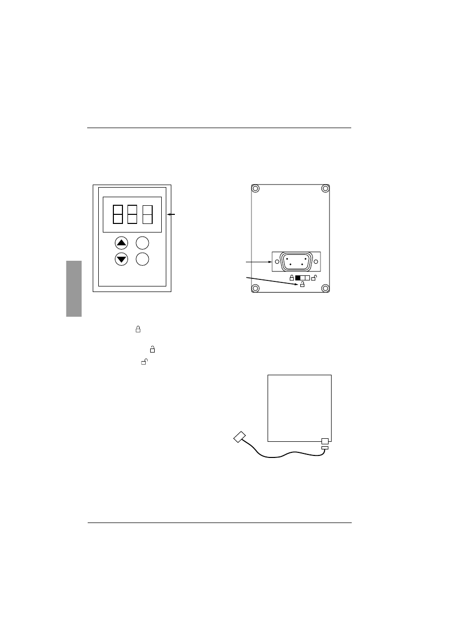
Remote terminal option
The
VW3 G48101
remote terminal can be mounted on the door of the wall-mounted or floor-standing enclosure
with a seal which offers IP 65 protection. It has a 3 m cable with connectors and communication is via the RJ45/
Modbus connection on the starter (
see the manual supplied with the terminal
). It has the same display and
the same programming buttons as the Altistart 48 with the addition of a menu access locking switch.
View of the front panel: View of the rear panel:
Control of the remote terminal switch
The 3-position switch on the terminal is used as follows:
• locked position
: only the monitoring parameters can be accessed. When the starter is running, it is
not possible to select a different parameter to be displayed.
• partly locked position
: limited access to the SEt, PrO and SUP menu parameters.
• unlocked position
: all parameters can be accessed.
Any display restrictions applied to the starter by the
remote terminal switch will still be in force once the
starter has been disconnected and even after it has
been switched off.
ESC
ENT
4-character
3-character
Connector
3-position switch
ATS48
RJ45
9-pin Sub D
129
ENGLISH
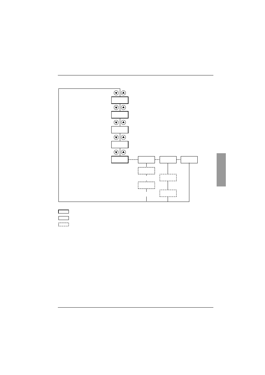
Settings menu (Set)
To access the parameters, see page 126.
ILt
In
ACC
tq0
StY
d
b
dEC
brC
EdC
EbA
F
Nominal motor current
Limiting current as a % of In
Initial starting torque
Acceleration ramp time
Selection of the type of stop
Deceleration
(pump)
Braking
Freewheel
Deceleration ramp time
Parameters in menu
Can be selected
Parameter appears according to selection
Threshold for changing to freewheel stop mode at the
end of deceleration
Internal braking torque level
Pseudo-continuous braking time
ENGLISH
130
Settings menu (Set)
The settings parameters can only be modified when the motor is stopped.
(1) Factory setting of In corresponding to the usual value of a 4-pole 400 V standardised motor with class 10
protection (for ATS 48•••Q).
Factory setting of In corresponding to the usual value of a 460 V standardised motor in accordance with
NEC and with class 10 protection (for ATS 48•••Y).
Code
Description
Setting
range
Factory
setting
I
I
I
In
n
n
n
Nominal motor current
0.4 to 1.3 ICL
(1)
Adjust the value of the nominal motor current indicated on the rating plate, even if the starter is
connected in the motor delta winding (dLt in the PrO menu).
Check that the current is between 0.4 and 1.3 ICL (ICL: starter rating).
I
I
I
IL
L
L
Lt
t
t
t
Limiting current
150 to 700%
of In, limited to
500% of ICL
400% of In
The limiting current ILt is expressed as a % of In.
It is limited to 500% of ICL (starter rating, see “Starter-motor combinations”, page 94.
Limiting current = ILt x In.
Example 1: In = 22 A, ILt = 300%, limiting current = 300% x 22 A = 66 A
Example 2: ATS 48C21Q, with ICL = 210 A
In = 195 A, ILt = 700%, limiting current = 700% x 195 = 1365,
limited to 500% x 210 = 1050 A
A
A
A
AC
C
C
CC
C
C
C
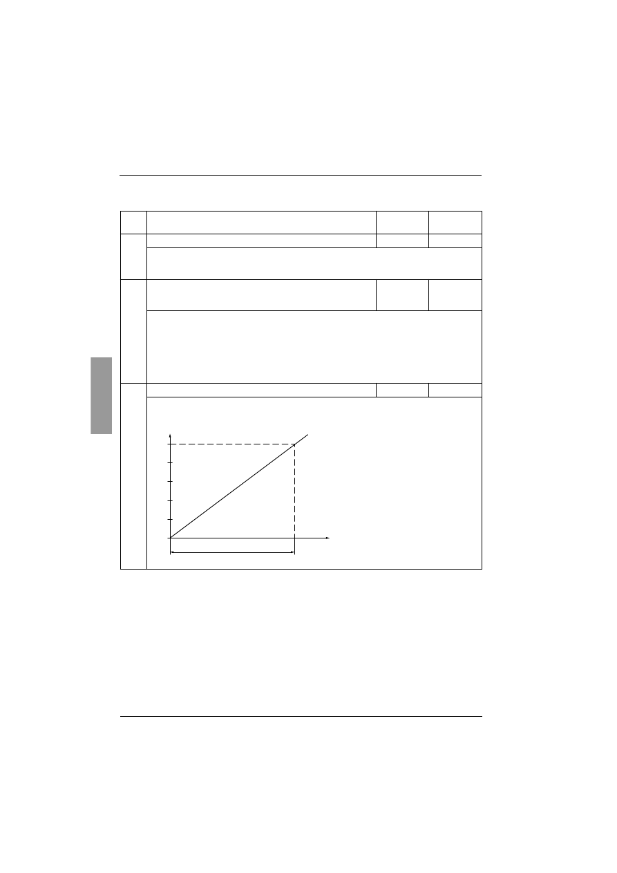
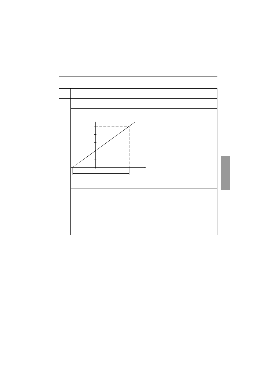
Acceleration ramp time
1 to 60 s
15 s
This is the rise time of the starter torque between 0 and the nominal torque Tn, i.e. the gradient of the
torque ramp on acceleration.
100
80
60
40
20
0
0
ACC
Time (s)
Reference torque
as a % of Tn
131
ENGLISH
Settings menu (Set)
Code
Description
Setting
range
Factory
setting
t
t
t
tq
q
q
q0
0
0
0
Initial starting torque
0 to 100% of
Tn
20%
Initial torque setting during the starting phases, varies from 0 to 100% of the nominal torque.
S
S
S
St
t
t
tY
Y
Y
Y
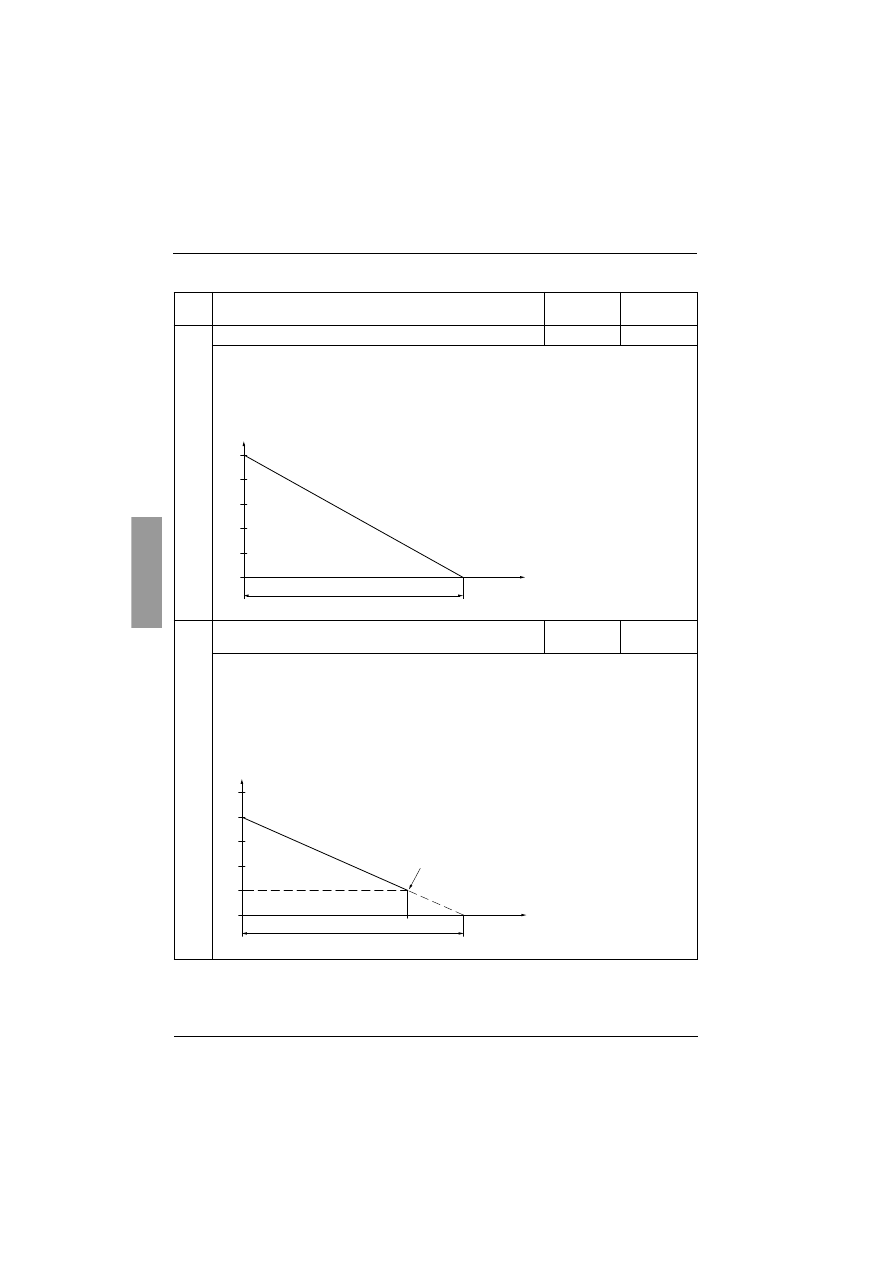
Selection of the type of stop
d-b-F
-F-
Three types of stop are possible:
- d -
: Soft stopping by control of torque. The starter applies a motor torque in order to decelerate
prgressively on the ramp, avoiding a rapid stop. This type of stop reduces the risk of water
hammer on a pump.
- b -
: Dynamic braking stop: The starter generates a braking torque in the motor which will slow the
motor down if there is considerable inertia.
- F -
: Freewheel stop: No torque is applied to the motor by the starter.
If the starter is connected to "delta in the motor", only stop type F is permitted.
100
tq0 = 40
80
60
40
20
0
0
Cn
ACC
Time (s)
ENGLISH
132
Settings menu (Set)
Code
Description
Setting
range
Factory
setting
d
d
d
dE
E
E
EC
C
C
C
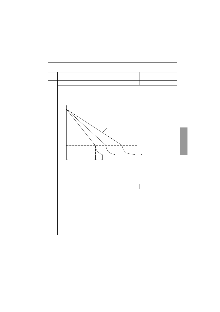
Deceleration ramp time
1 to 60 s
15 s
This parameter can only be accessed if StY = -d-.
Can be used to set a time between 1 to 60 s to switch from the estimated torque to zero torque (=
gradient of the torque ramp on deceleration when a -d- stop is applied).
This modifies the progression of the deceleration and avoids hydraulic shocks in pump applications
by modifying the gradient of the torque reference.
E
E
E
Ed
d
d
dC
C
C
C
Threshold for changing to freewheel stop mode at the end of
deceleration
0 to 100%
20%
This parameter can only be accessed if StY = -d- and if the CLP parameter in the drive menu (drC)
is still set to the factory setting (On).
Can be used to set the final torque level between 0 and 100% of the estimated torque at the start of
deceleration.
In pump applications, deceleration control is not necessarily below a load level set by Edc.
If the estimated torque at the start of deceleration is below 20, i.e. 20% of the nominal torque,
controlled deceleration is not activated, and the motor changes to freewheel mode.
100
80
60
40
20
0
dEC
Time (s)
Estimated torque as a % of the nominal torque
100
80
60
40
20
0
dEC
EdC
Time (s)
Estimated torque as a % of the nominal torque
End of controlled deceleration
133
ENGLISH
Settings menu (Set)
Code
Description
Setting
range
Factory
setting
b
b
b
br
r
r
rC
C
C
C
Internal braking torque level
0 to 100%
50%
This parameter can only be accessed if StY = -b-.
For stop type -b-, used to adjust the braking intensity.
Braking is active up to 20% of the nominal speed. The total stop of the motor is configured by
adjusting the injection time of the pseudo-continuous current in the motor (on two phases). See the
next parameter EbA.
Pseudo-continuous injection time: T2 = T1 x EbA
Note: Time T1 is not determined by brC. T1 is the time required in seconds for the motor to fall from
100% of the nominal speed to 20% (depends on the motor and application characteristics).
E
E
E
Eb
b
b
bA
A
A
A
Pseudo-continuous braking time
20 to 100%
20%
This parameter can only be accessed if StY = -b-.
For stop type -b-, adjustment of the current injection time at the end of braking.
Can be used to adjust the current injection time.
Can be set at 20 to 100% of the dynamic braking time (T1).
Example:
Dynamic braking = 10 s (T1)
The stopping time can vary from 2 to 10 s (T2)
EbA = 20 Corresponds to an injection time of 2 s
EbA = 100 Corresponds to an injection time of 10 s
Factory setting: 20
100 %
20 %
0
T1
T2
brc = 0
brc = 100
Motor speed
Dynamic
braking time
Adjustment of motor
stop by EbA
ENGLISH
134
Protection menu (PrO)
To access the parameters, see page 126.
PHr
tHP
tbS
PHL
ULL
ALA
dEF
OFF
LUL
tUL
LOC
tOL
tLS
OIL
ALA
dEF
OFF
PtC
ArS
rtH
Activation of motor underload
Motor thermal protection
Protection classes 10, 20, etc.
Alarm
Fault
Deactivation
Parameters in menu
Can be selected
Parameter appears according to selection
Motor underload time
Excessive starting time (fault)
in seconds
Activation of current overload
Alarm
Fault
Deactivation
Current overload time
Acceptance of phase rotation, 123, 321
Time before restarting
Phase loss threshold
Activation of motor monitoring by PTC probes
Automatic restart
Reset thermal state
Motor underload threshold as a %
of the nominal torque
Current overload level as a %
of the nominal current
135
ENGLISH
Protection menu (PrO)
The protection parameters can only be modified when the motor is stopped.
The configuration of a monitoring alarm (ALA) indicates the presence of a fault but will not
directly protect the installation
Code
Description
Setting
range
Factory
setting
t
t
t
tH
H
H
HP
P
P
P
Motor thermal protection
10
See “Thermal protection”, page 121.
30: class 30
25: class 25
20: class 20 (severe application)
15: class 15
10: class 10 (standard application)
10A: class 10A
2: sub-class 2
OFF: no protection
U
U
U
UL
L
L
LL
L
L
L
Activation of motor underload
OFF
If the motor torque is less than an adjustable threshold LUL for a period of time longer than an
adjustable value tUL:
- ALA: an alarm is activated (internal bit and configurable logic output)
- dEF: the starter is locked and the ULF fault is displayed
- OFF: no protection
L
L
L
LU
U
U
UL
L
L
L
Motor underload threshold
20% to 100%
of Tn
60%
This parameter is not available if ULL = OFF.
LUL can be set at between 20% and 100% of the nominal motor torque.
t
t
t
tU
U
U
UL
L
L
L
Motor underload time
1 to 60 s
60 s
This parameter is not available if ULL = OFF.
Time delay tUL is activated as soon as the motor torque falls below threshold LUL. It is reset to zero
if the torque rises above this threshold LUL by + 10% (hysteresis).
t
t
t
tL
L
L
LS
S
S
S
Excessive starting time
10 to 999 s or
OFF
OFF
If the starting time exceeds the value of tLS, the starter is locked and displays the fault StF. The
conditions for the end of starting are: line voltage applied to the motor (min. firing angle) and motor
current less than 1.3 In.
- OFF: no protection
20 %
(Cn) 100 %
t
T
LUL
+10 %
ULL
< tUL
tUL
(hysteresis)
detection
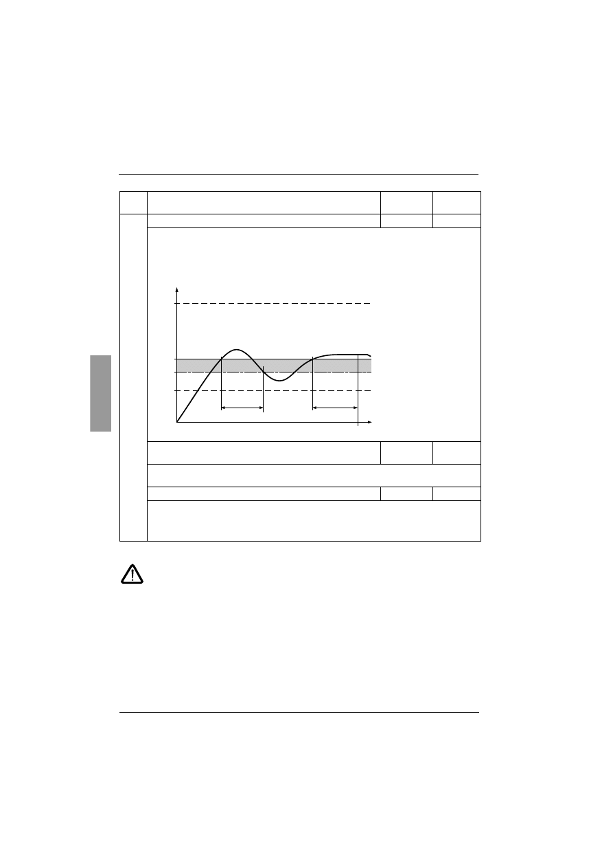
ENGLISH
136
Protection menu (PrO)
The factory configuration of a monitoring alarm (ALA) indicates the presence of a fault but
will not directly protect the installation
Code
Description
Setting
range
Factory
setting
O
O
O
OI
I
I
IL
L
L
L
Activation of current overload
OFF
Function active only in steady state
If the motor current exceeds an adjustable threshold LOC for a period of time longer than an
adjustable value tOL:
-
ALA: an alarm is activated (internal bit and configurable logic output)
- dEF: the starter is locked and the OLC fault is displayed
- OFF: no protection
L
L
L
LO
O
O
OC
C
C
C
Current overload threshold
50% to 300%
of In
80%
This parameter is not available if OIL = OFF.
LOC can be set at between 50% and 300% of the nominal motor current.
t
t
t
tO
O
O
OL
L
L
L
Current overload time
0.1 to 60 s
10 s
This parameter is not available if OIL = OFF.
Time delay tOL is activated as soon as the motor current rises above threshold LOC. It is reset to
zero if the current falls below this threshold LOC again by at least 10% (hysteresis).
50 %
300 %
I
t
OIL
LOC
tOL
< tOL
-10 %
(hysteresis)
detection
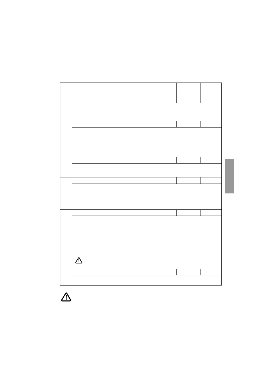
137
ENGLISH
Protection menu (PrO)
The factory configuration of a monitoring alarm (ALA) indicates the presence of a fault but
will not directly protect the installation
Code
Description
Setting
range
Factory
setting
P
P
P
PH
H
H
Hr
r
r
r
Protection against line phase inversion
321 or 123 or
no
no
If the line phases are not in the order configured, the starter locks and displays the fault PIF.
- 321: reverse (L3 - L2 - L1)
- 123: forward (L1 - L2 - L3)
- no: no monitoring
t
t
t
tb
b
b
bS
S
S
S
Time before starting
0 to 999 mn
2 mn
Avoids starts in quick succession which may overheat the motor. The time delay starts when the
motor changes to freewheel mode.
In 2-wire control, the motor is restarted after the time delay if the RUN command input is still
activated.
In 3-wire control, the motor is restarted after the time delay if a new RUN command is sent (rising
edge).
The starter displays "tbS" during the time delay.
P
P
P
PH
H
H
HL
L
L
L
Phase loss threshold
5 to 10%
10%
If the motor current falls below this threshold in one phase for 0.5 s or in all three phases for 0.2 s,
the starter locks and displays the fault PHF.
Can be set at between 5 and 10% of the ICL starter rating.
P
P
P
Pt
t
t
tC
C
C
C
Activation of motor monitoring by PTC probes
OFF
The PTC probes on the motor must be connected to the correct analog input. This protection is
independent of the calculated thermal protection (tHP parameter). Both types of protection can be
used simultaneously.
- ALA: an alarm is activated (internal bit and assignable logic output)
- dEF: the starter is locked and the OtF fault is displayed
- OFF: no protection
A
A
A
Ar
r
r
rS
S
S
S
Automatic restart
On - OFF
OFF
After locking on a fault, if the fault has disappeared and the other operating conditions permit the
restart.
A series of automatic attempts are made to restart the starter at intervals of 60 s. If a restart has not
been possible after 6 attempts, the procedure is abandoned and the starter remains locked until it is
switched off then switched on again or reset manually (see "Faults - causes - remedies"). The
following faults permit this function: PHF, FrF, CLF, USF. The starter fault relay remains activated if
this function is active. The run command must be maintained.
This function can only be used in 2-wire control.
- OFF: Function inactive
- On: Function active
Check that an accidental start will not endanger personnel or equipment in any way
r
r
r
rt
t
t
tH
H
H
H
Reset motor thermal state calculated by the starter
no - YES
no
- no: Function inactive
- YES: Function active
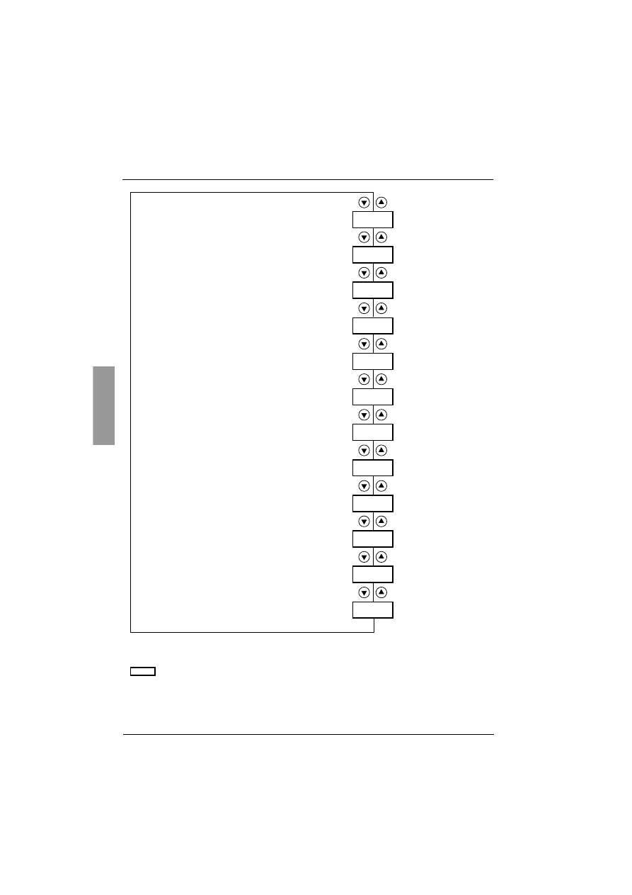
ENGLISH
138
Advanced settings menu (drC)
bSt
tLI
dLt
SSt
CLP
LSC
tIG
CSC
ULn
FrC
rPr
FCS
Parameters in menu
Torque limit as a % of the nominal torque
Voltage boost level
Starter with delta winding connection
Tests on small motor
Torque control
Stator loss compensation
Deceleration gain
Activation of the cascade function
Line voltage (to calculate P in kW)
Line frequency
Reset kWh or the operating time
Return to factory settings
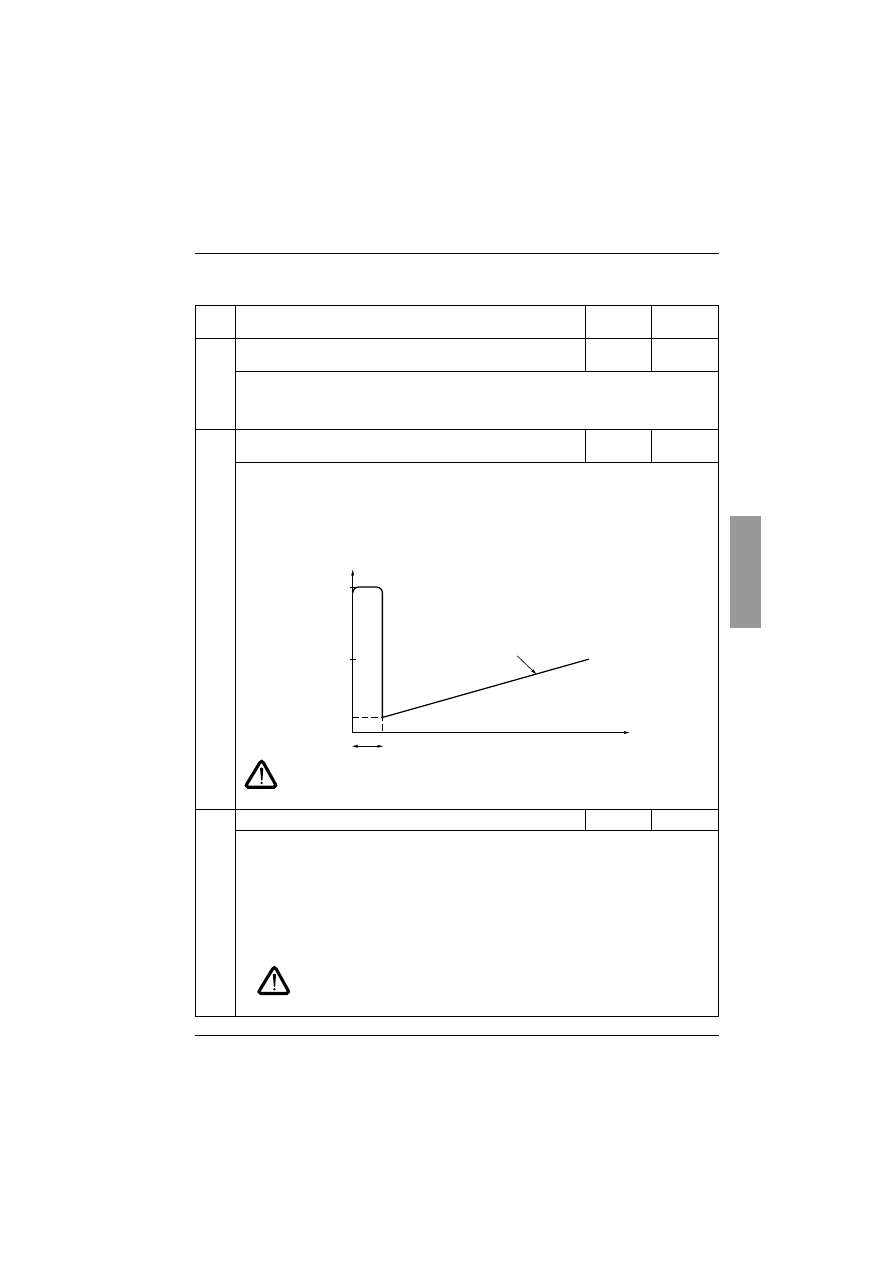
139
ENGLISH
Advanced settings menu (drC)
The Advanced setting parameters can only be modified when the motor is stopped.
Code
Description
Setting
range
Factory
setting
t
t
t
tL
L
L
LI
I
I
I
Torque limit
10 to 200%
or OFF
OFF
Can be used to limit the torque reference to avoid regenerative behaviour in applications with high
inertia. Can be used for constant torque starting if tqO = tLI.
- OFF: no limit
- 10 to 200: limit set as a % of the nominal torque
b
b
b
bS
S
S
St
t
t
t
Voltage boost level
50 to 100%
or OFF
OFF
An adjustable voltage can be applied when a run command is present for 100 ms. Once this time
has elapsed, the starter follows a standard acceleration ramp starting at the initial torque value set
(tq0).
This function can be used to avoid any "starting" torque (phenomenon caused by friction on
stopping or by mechanical play).
- OFF: Function inactive
- 50 to 100: setting as a % of the nominal motor voltage
In the case of overrating the starter (Im motor> Im ATS48), a value of the parameter
bSt too high can cause the starter to trip in OCF
d
d
d
dL
L
L
Lt
t
t
t
Starter with delta winding connection
on - OFF
OFF
This configuration will permit a rating increase of 1.7 in the starter power but does not permit braking
or deceleration.
- OFF: normal line torque
- On: motor with delta winding connection
The nominal motor current In is the same as that specified on the motor rating plate and the current
displayed corresponds to the line current of the line supply. The nominal current value In (SEt
menu) is the same as that specified on the motor rating plate for the delta connection. The starter
carries out the conversion itself to control the current in the windings.
This parameter can only be accessed for ATS 48
•••Q
starters.
• With this function, only freewheel type stopping is possible
• Cascading is not possible
• Preheating is not possible
50 %
Un
100 ms
100 %
Un
t
U
T
tq0
Ts
Torque ramp
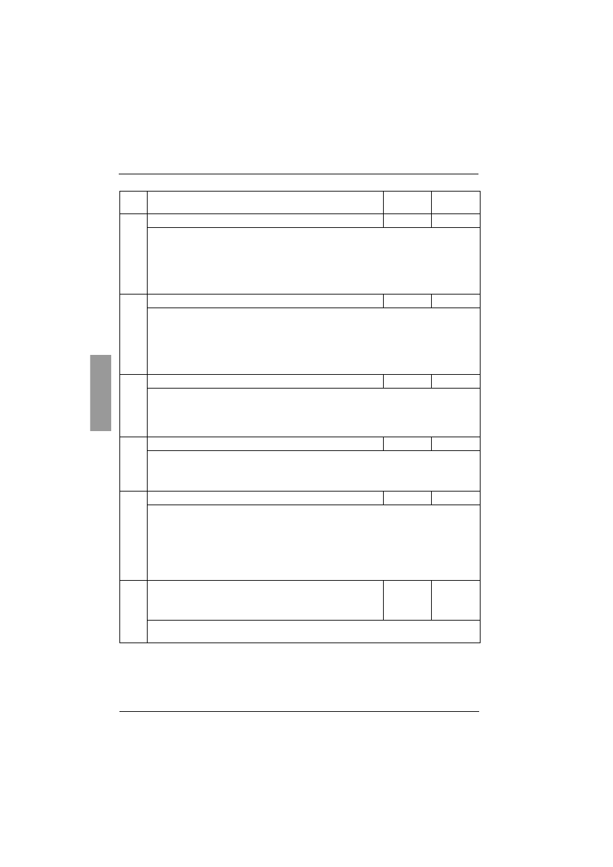
ENGLISH
140
Advanced settings menu (drC)
Code
Description
Setting
range
Factory
setting
S
S
S
SS
S
S
St
t
t
t
Tests on small motor
On - OFF
OFF
To check the starter in a testing or maintenance environment, on a motor whose power is very much
lower than the starter rating (in particular for high power starters).
The torque control parameter CLP is automatically deactivated.
- OFF: function inactive
- On: function active
SSt returns to the OFF state as soon as the control voltage is disconnected. On the next
power up, the PHF fault and the CLP parameter return to their initial configuration.
C
C
C
CL
L
L
LP
P
P
P
Torque control
(type of control)
On-OFF
On
- OFF: function inactive
- On: function active
In the On position, starting and deceleration follow the torque ramp.
In the OFF position, starting and deceleration are controlled by voltage variation.
Voltage control is recommended for applications which use motors in parallel on one starter or a
motor whose power is very low in relation to the starter rating (use of an undersized motor to test
the starter) (CLP = OFF).
L
L
L
LS
S
S
SC
C
C
C
Stator loss compensation
0 to 90%
50%
Parameter active in acceleration phases (and deceleration phases if StY = -d-).
In the event of torque oscillations, reduce this parameter gradually until the device is functioning
correctly.
Oscillations are most common if the starter is connected in the motor delta winding or in motors with
excessive slip.
t
t
t
tI
I
I
IG
G
G
G
Deceleration gain
(for torque control)
10 to 50%
40%
This parameter can only be accessed if CLP = On and if the StY parameter (SEt Settings menu) =
-d-.
Can be used to eliminate instability during deceleration.
Adjust the parameter in accordance with the oscillations.
C
C
C
CS
S
S
SC
C
C
C
Activation of the cascade function
On-OFF
OFF
See page 120
- On: function active
- OFF: function inactive
This parameter can only be accessed if relay R1 has previously been assigned to the "isolating
relay" function and if the "forced freewheel stop", "starter in the motor delta winding" and
"preheating" functions are not configured.
Assign an input LI = LIC.
255 motors max.
U
U
U
UL
L
L
Ln
n
n
n
Line voltage
170 to 460 V
(ATS48••Q)
180 to 790 V
(ATS48••Y)
400 V
(ATS48••Q)
690 V
(ATS48••Y)
This parameter is used to calculate the power displayed (LPr and LAP parameters from the SUP
menu). The display will only be accurate if this parameter has been set correctly.

141
ENGLISH
Advanced settings menu (drC)
Code
Description
Adjustme
nt range
Factory
setting
F
F
F
Fr
r
r
rC
C
C
C
Line frequency
50-60-
AUt
AUt
- 50: 50 Hz (monitoring tolerance of frequency fault FrF = ± 20%).
- 60: 60 Hz (monitoring tolerance of frequency fault FrF = ± 20%).
- AUt: automatic recognition of the line frequency by the starter with frequency fault monitoring
tolerance FrF = ± 5%.
Selections 50 and 60 are recommended if the power supply is provided by a generating set, given
their high tolerance.
r
r
r
rP
P
P
Pr
r
r
r
Reset kWh or the operating time
no-APH-
trE
no
- no: function inactive
- APH: kWh reset to zero
- trE: operating time reset to zero
The reset command must be confirmed with ENT. APH and trE take effect immediately. The
parameter then automatically returns to no.
F
F
F
FC
C
C
CS
S
S
S
Return to factory settings
no-YES
no
Used to reset all parameters to their factory settings.
- no: function inactive
- YES: function active, must be pressed and held down (for approx. 2 s) in order to be taken into
account. The display flashes to confirm. The FCS parameter is then automatically reset to no by
pressing ESC.
This parameter cannot be modified via the remote terminal.
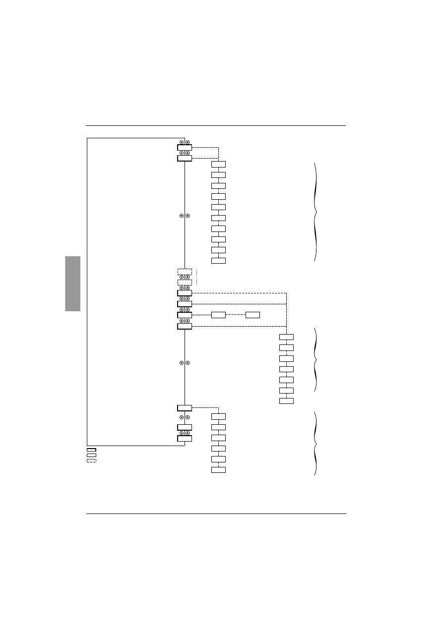
ENGLISH
142
I/O menu (IO)
LI3
LI4
no
IPr
tPr
LO1
LO2
r1
r3
0-4
ASC
AO
LIA
LIE
LIH
LIL
LII
LIt
LIC
LIr
LIS
no
Ocr
Otr
OtH
OCO
OPr
rIF
rII
no
tAI
rn1
AIL
AUL
APC
AS2
Parameters in menu
Can be selected
Parameter appears according to selection
Assignment of logic input LI3
Assignment of logic input LI4
Not assigned
Forced freewheel stop
External fault
Motor preheating
Force to local control mode
Inhibits all protection
Reset motor thermal fault
Activation of the cascade function
Reset faults
Activation of second
set of motor parameters
Preheating level
(if preheating is selected)
Time delay before preheating
0 to 999 s
Parameters
visible if
LIH assigned
Fault relay
Isolating relay
Assignment of logic output LO1
Assignment of logic output LO2
Assignment of relay R1
Assignment of relay R3
Not assigned
Thermal alarm motor 1
Motor powered
Motor underload alarm
PTC probe alarm
Second set of motor parameters activated
Assignment of analog output AO
Not assigned
Motor current
Motor torque
Motor thermal state
Cosine
ϕ
Active power
Configuration of the analog output
Scale setting of max. signal of
analog output
Motor current alarm
Can be
selected
Can be
selected
Can be
selected
To access the parameters see page 126
Note
Logic input RUN: cannot be assigned
Logic input STOP: cannot be assigned
Starter bypass contactor control: cannot be assigned (R2)

143
ENGLISH
I/O menu (IO)
The I/O parameters can only be modified when the motor is stopped.
(1) In order for this assignment o take effect, ENT must be pressed for 10 s (confirmed by flashing display).
This parameter cannot be modified via the remote terminal.
Code
Description
Setting
range
Factory
setting
L
L
L
LI
I
I
I3
3
3
3
L
L
L
LI
I
I
I4
4
4
4
Logic inputs
LIA
LIL
The selected function is active if the input is powered up.
- no: not assigned.
- LIA: forced freewheel stop as soon as a STOP command is received. This selection does not
appear if the CSC parameter in the drC menu is set to "On". Forces the configuration of a
freewheel type stop, but does not control the stop.
- LIE: external fault. Enables the starter to detect an external user fault (level, pressure, etc.). The
motor comes to a freewheel stop and the starter displays EtF.
- LIH: (1) motor preheating. This selection does not appear if the CSC parameter in the drC menu
is set to "On". Used to prevent the motor from freezing or to prevent temperature deviations
which may cause condensation. Once the motor has stopped an adjustable current IPr flows
through it after an adjustable time delay tPr, if the input is active. This current heats the motor
without causing it to rotate. IPr and tbr must be adjusted (see below).
Preheating starts when the input is activated and the motor has stopped, after time delays
tPr and tbS (PrO menu) have elapsed. Preheating stops if the input is deactivated, if a run
command is sent or if the STOP input is activated.
- LIL: force to local control mode.
If a serial link is used, changes from line mode (control via serial
link) to local mode (control via terminals).
- LII: (1) inhibits all protection. Warning: This type of use invalidates the starter warranty. Used to
override the starter in the event of an emergency (smoke extraction system for example).
- LIt: reset motor thermal fault
- LIC: activation of the cascade function. In this case motor thermal protection is disabled and relay
R1 must be configured as an isolating relay. Can be used to start and decelerate several
identical motors one after the other with a single starter (see application diagram).
- LIr: reset faults which can be reset
- LIS: activation of second set of motor parameters. Used to start and decelerate two different
motors one after the other or one motor with two different configurations using a single starter.
RUN
LI
tbS
tPr
Speed
IPr current
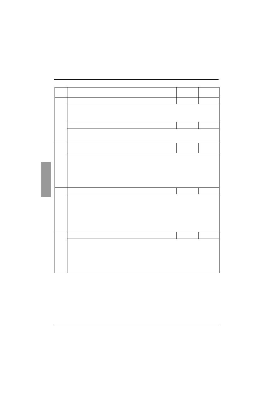
ENGLISH
144
I/O menu (IO)
Code
Description
Setting
range
Factory
setting
I
I
I
IP
P
P
Pr
r
r
r
Preheating level
0 to 100%
0%
This parameter appears after LI3 or LI4 have been assigned to function
LIH: motor preheating. It
can be used to set the preheating current. Use a true value current reading ammeter to set the
current level.
Parameter In has no effect on the current IPr.
t
t
t
tP
P
P
Pr
r
r
r
Time delay before preheating
0 to 999 s
5 s
This parameter appears after LI3 or LI4 have been assigned to function
LIH: motor preheating.
Preheating starts when the input is activated, after time delays tPr and tbS (PrO menu) have
elapsed.
L
L
L
LO
O
O
O1
1
1
1
L
L
L
LO
O
O
O2
2
2
2
Logic outputs
tAI
rnI
- no: not assigned.
- tAI: motor thermal alarm. See page 121.
- rnI: motor powered (indicates that there may be current in the motor).
- AIL: motor current alarm (threshold OIL and time tOL of PrO menu exceeded). See “
Function
active only in steady state”, page 136.
- AUL: motor underload alarm (threshold LUL and time tUL of PrO menu exceeded). See page 135.
- APC: motor PTC probe alarm. See “Activation of motor monitoring by PTC probes”, page 137.
- AS2:
second set of motor parameters activated. See LIS “Logic inputs”, page 143.
r
r
r
r1
1
1
1
Relay R1
rIF
- rIF: fault relay. Relay R1 is activated when the starter is powered up (minimum CL1/CL2 control).
Relay R1 is deactivated when a fault occurs and the motor switches to freewheel mode. See
the special case when the automatic restart function is activated and Faults - causes -
remedies.
- rII: isolating relay. Relay R1 is designed to control the line contactor on the basis of the RUN and
STOP commands and to indicate faults. Relay R1 is activated by a RUN command (or a
preheating command). It is deactivated at the end of braking or deceleration or when the
motor switches to freewheel mode after a STOP command. It is also deactivated when a fault
occurs. The motor switches to freewheel mode at this point.
r
r
r
r3
3
3
3
Relay R3
rnI
- no: not assigned.
- tAI: motor thermal alarm. See page 121.
- rnI: motor powered (indicates that there may be current in the motor).
- AIL: motor current alarm (threshold OIL and time tOL of PrO menu exceeded). See “
Function
active only in steady state”, page 136.
- AUL: motor underload alarm (threshold LUL and time tUL of PrO menu exceeded). See page 135.
- APC: motor PTC probe alarm. See “Activation of motor monitoring by PTC probes”, page 137.
- AS2:
second set of motor parameters activated. See LIS “Logic inputs”, page 143.

145
ENGLISH
I/O menu (IO)
End of starting relay R2
(cannot be assigned)
The end of starting relay R2 is activated when the starter is powered up, no faults are present and the motor
has completed the start-up phase. It is deactivated in the event of a stop request or a fault. It has one normally
open contact (N/O).
It can be used to bypass the ATS 48 at the end of the starting phase.
Code
Description
Setting
range
Factory
setting
A
A
A
AO
O
O
O
Analog output
OCr
- no: not assigned
- OCr: motor current
- Otr: motor torque
- OtH: motor thermal state
- OCO: cosine
ϕ
- OPr: active power
O
O
O
O
4
4
4
4
Configuration of the type of signal supplied by output AO
020 - 420
020
- 020: 0 - 20 mA signal
- 420: 4 - 20 mA signal
A
A
A
AS
S
S
SC
C
C
C
Scale setting of max. signal of the analog output
50 to 500%
200
As a percentage of the nominal value of the parameter configured or of 1 for the cosine
ϕ
.
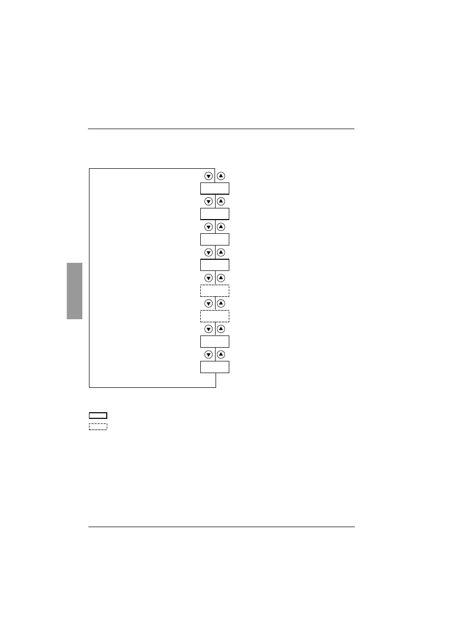
ENGLISH
146
2nd motor parameters menu (St2)
The parameters for 1st or 2nd motor are selected by the logic input (LIS). Taking into account the motor
parameters selected :
In2
IL2
AC2
tq2
dE2
Ed2
tL2
tI2
Parameters in menu
Paramèter appears according to the selection and to the assignement of StY in the SET menu
Nominal motor current
Limiting current
Acceleration ramp time
Initial starting torque
Deceleration ramp time
Threshold for changing to
freewheel stop mode at the end
of deceleration
Maximum torque limiting
Deceleration gain
On the next deceleration
On the next deceleration
On the next acceleration
Immediately
On the next acceleration
On the next acceleration
Immediately
On the next deceleration
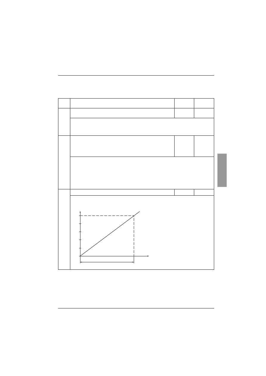
147
ENGLISH
2nd motor parameters menu (St2)
This menu is only visible if a logic input is assigned to the function for activating a second set of motor
parameters (LIS) in the I/O menu.
(1) Factory setting of In2 corresponding to the usual value of a 4-pole 400 V standardised motor with class 10
protection (for ATS 48•••Q).
Factory setting of In2 corresponding to the usual value of a 460 V standardised motor in accordance with
NEC and with class 10 protection (for ATS 48•••Y).
Code
Description
Setting
range
Factory
setting
I
I
I
In
n
n
n2
2
2
2
Nominal motor current
0.4 to 1.3
ICL
(1)
Adjust the value of the nominal motor current indicated on the rating plate, even if the starter is
connected in the motor delta winding (PrO).
Check that the current is between 0.4 and 1.3 ICL (ICL: starter rating). See “Starter-motor
combinations”, page 94.
I
I
I
IL
L
L
L2
2
2
2
Limiting current
150 to
700% of In,
limited to
500% of
ICL
400% of In
The limiting current IL2 is expressed as a % of In2.
It is limited to 500% of ICL (starter rating, see “Starter-motor combinations”, page 94).
Limiting current = IL2 x In2
Example 1: In2 = 21 A, IL2 = 300%, limiting current = 300% x 22 A = 66 A
Example 2: ATS 48C21Q, with ICL = 210 A
In2 = 195 A, IL2 = 700%, limiting current = 700% x 195 = 1365,
limited to 500% x 210 = 1050 A
A
A
A
AC
C
C
C2
2
2
2
Acceleration ramp time
1 to 60 s
15 s
This is the rise time of the starter torque between 0 and the nominal torque Tn, i.e. the gradient of
the torque ramp on acceleration.
100
80
60
40
20
0
0
AC2
Time (s)
Reference torque
as a % of Tn
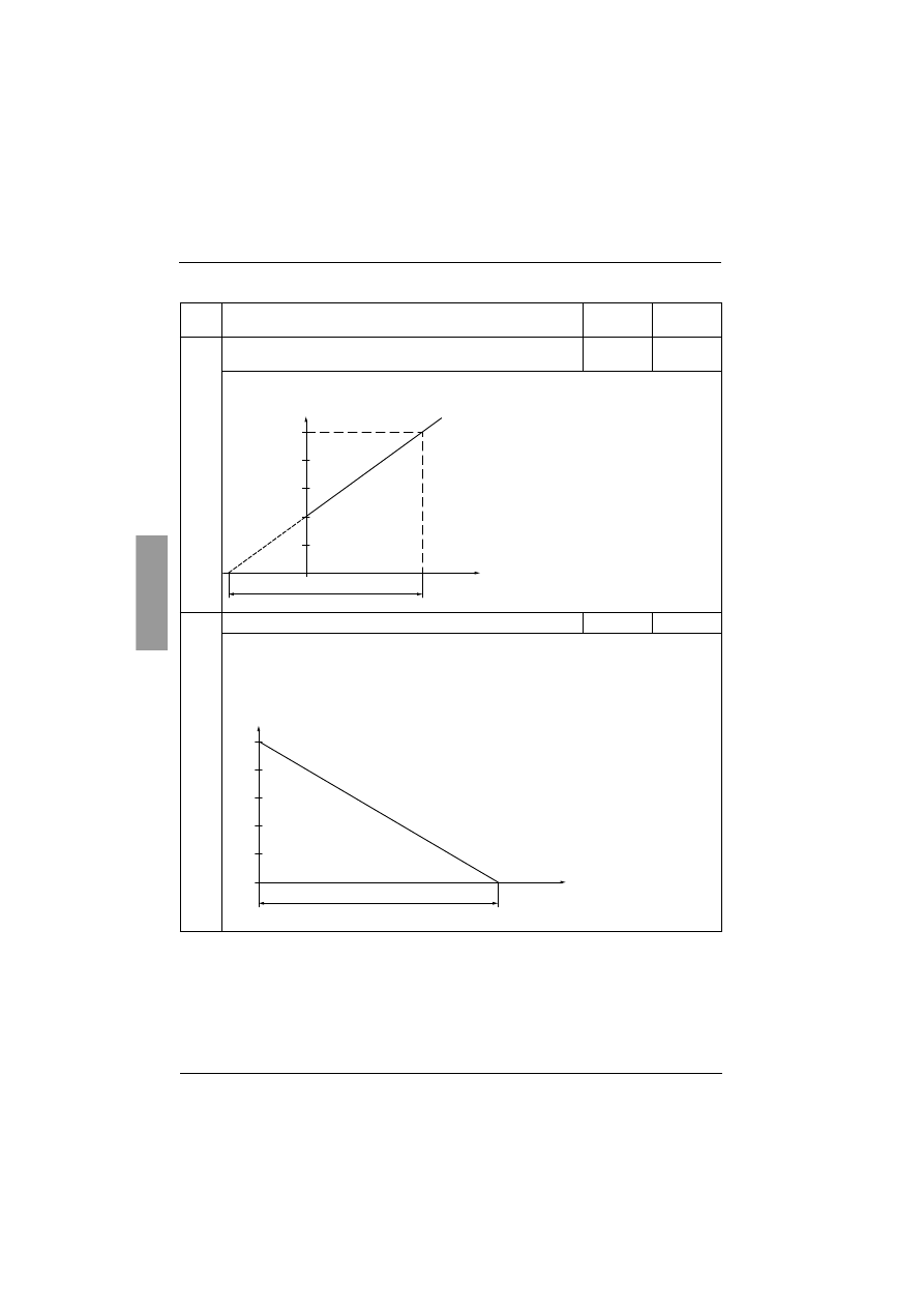
ENGLISH
148
2nd motor parameters menu (St2)
Code
Description
Setting
range
Factory
setting
t
t
t
tq
q
q
q2
2
2
2
Initial starting torque
0 to 100%
of Tn
20%
Initial torque setting during the starting phases, varies from 0 to 100% of the nominal torque.
d
d
d
dE
E
E
E2
2
2
2
Deceleration ramp time
1 to 60 s
15 s
This parameter can only be accessed if StY = -d-.
Used to set a time between 1 to 60 s to switch from the estimated torque to zero torque (= gradient
of the torque ramp on deceleration when a -d- stop is applied).
This modifies the progression of the deceleration and avoids hydraulic shocks in pump applications
by modifying the gradient of the torque reference.
100
tq2 = 40
80
60
40
20
0
0
Cn
AC2
Time (s)
100
80
60
40
20
0
dE2
Time (s)
Estimated torque as a % of the nominal torque
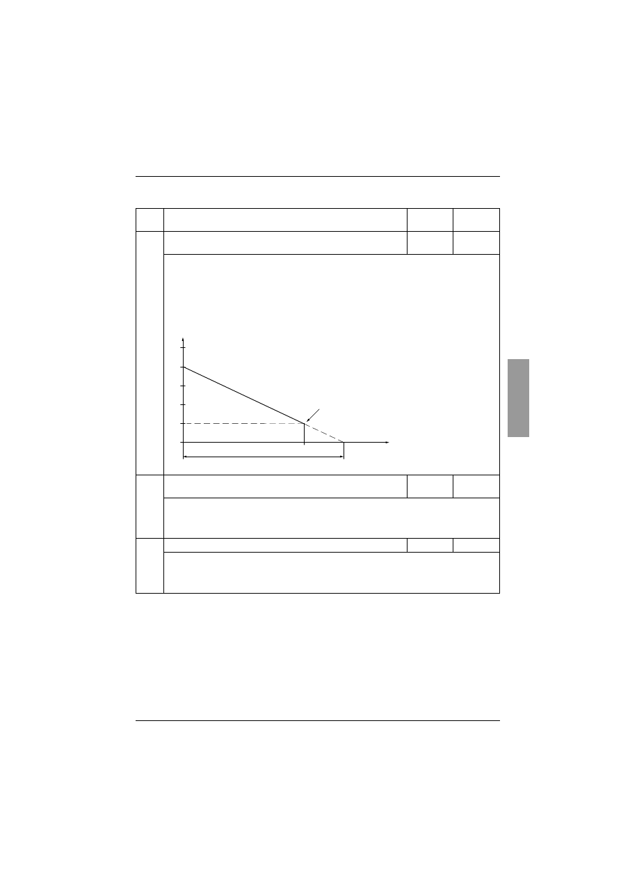
149
ENGLISH
2nd motor parameters menu (St2)
Code
Description
Setting
range
Factory
setting
E
E
E
Ed
d
d
d2
2
2
2
Threshold for changing to freewheel stop mode at the end of
deceleration
0 to 100%
20%
This parameter can only be accessed if StY = -d- and if the CLP parameter in the drive menu (drC)
is still set to the factory setting (On).
Used to set the final torque level between 0 and 100% of the torque estimated at the beginning of
deceleration.
In pump applications, deceleration control is not necessarily below a load level set by Edc.
If the estimated torque at the start of deceleration is below 20, i.e. 20% of the nominal torque,
controlled deceleration is not activated, and the motor changes to freewheel mode.
t
t
t
tL
L
L
L2
2
2
2
Maximum torque limit
10 to 200%
or OFF
OFF
Used to limit the torque reference to avoid regenerative behaviour in applications with high inertia.
Can be used for constant torque starting if tq2 = tLI.
- OFF: no limit
- 10 to 200: limit set as a % of the nominal torque
t
t
t
tI
I
I
I2
2
2
2
Deceleration gain
(for torque control)
10 to 50%
40%
This parameter can only be accessed if CLP = On and if the StY parameter (SEt Settings menu) =
-d-.
Used to eliminate instability during deceleration.
Adjust the parameter in accordance with the oscillations.
100
80
60
40
20
0
dE2
Ed2
Time (s)
Estimated torque as a % of the nominal torque
End of controlled deceleration
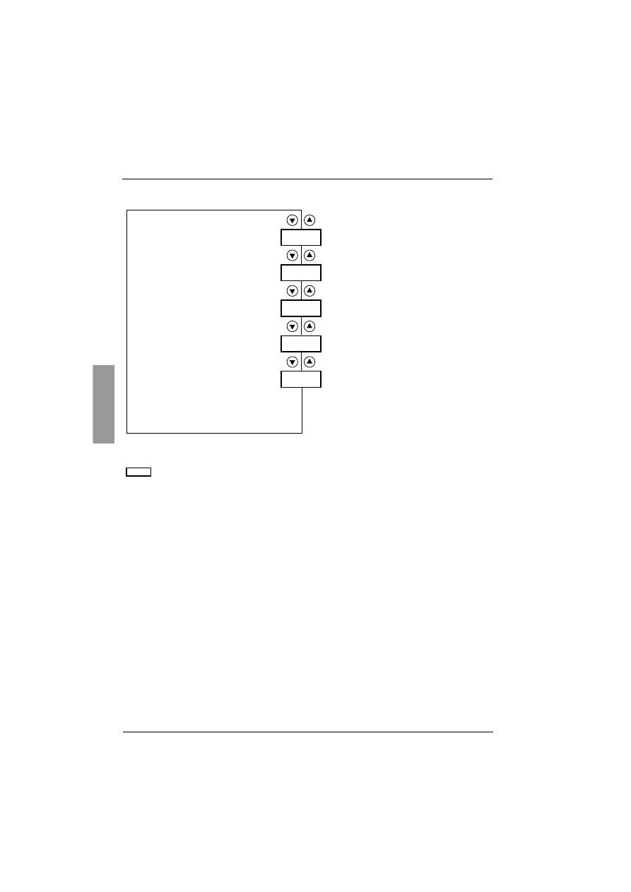
ENGLISH
150
Communication menu (COP)
Add
tbr
FOr
tLP
PCt
Parameters in menu
Starter address
Communication speed
Communication format
Serial link timeout setting
Configuration of the link for
communication with the remote terminal
or the software workshop
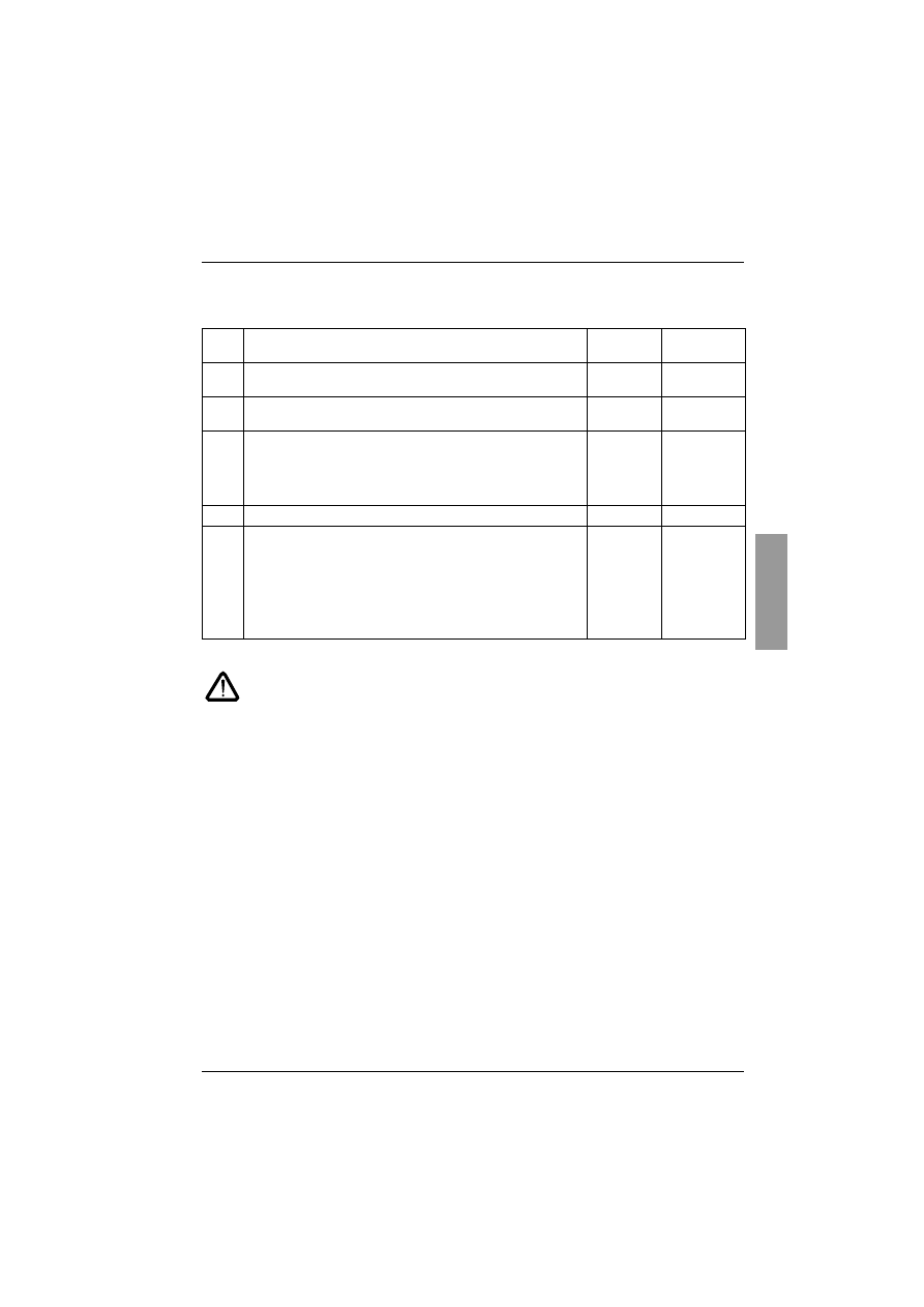
151
ENGLISH
Communication menu COP
The communication menu parameters can only be modified when the motor is stopped.
The internal protocol used is Modbus.
(1) Check that the time set will not interfere with the safe operation of the machine
Code
Description
Setting
range
Factory
setting
A
A
A
Ad
d
d
dd
d
d
d
Starter address
by the RS485 serial link
0 to 31
0
t
t
t
tb
b
b
br
r
r
r
Communication speed
in kbps
.
4.8 - 9.6 -
19.2
19.2
F
F
F
FO
O
O
Or
r
r
r
Communication format
8o1: 8 data bits, odd parity, 1 stop bit
8E1: 8 data bits, even parity, 1 stop bit
8n1: 8 data bits, no parity, 1 stop bit
8n2: 8 data bits, no parity, 2 stop bits
8n1
t
t
t
tL
L
L
LP
P
P
P
Serial link timeout setting
(1)
0.1 to 60 s
5 s
P
P
P
PC
C
C
Ct
t
t
t
Configuration of the serial link for communication with the
remote terminal
On: function active. Temporarily configures the starter (tbr and FOr)
for communication with the remote terminal.
OFF: function inactive
PCT returns to the OFF state as soon as the control voltage is
disconnected. On the next power up, the tbr and FOr
parameters return to their initial configuration.
OFF
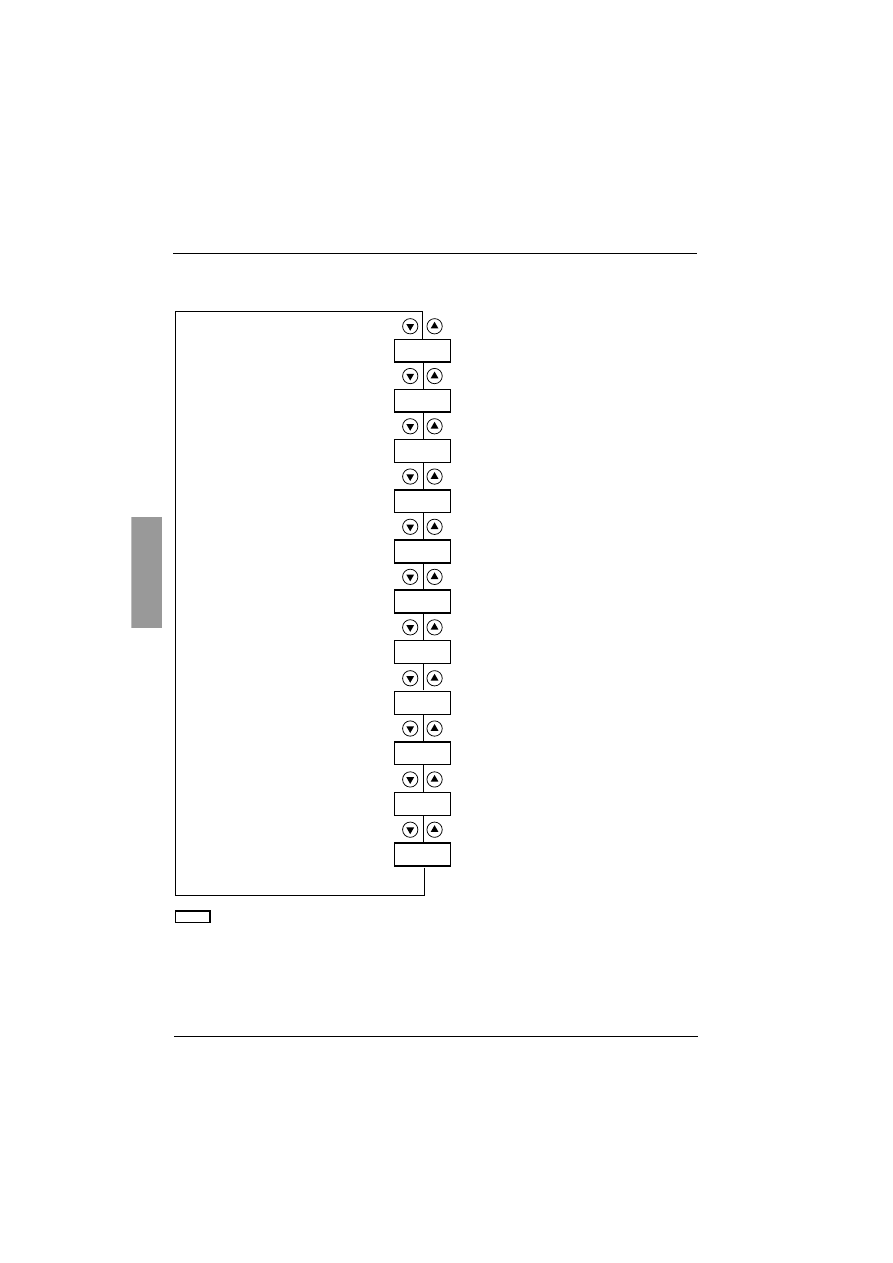
ENGLISH
152
Parameter displayed menu (SUP)
COS
tHr
LCr
rnt
LPr
Ltr
LAP
EtA
LFt
PHE
COd
Parameters in menu
Cosine
ϕ
Motor thermal state as a %
Motor current
Operating time since the last reset
Active power as a %
Motor torque as a %
Active power in kW
Display of the current state
(ACC, rUn, dEC, etc.)
Phase rotation direction, 1-2-3
or 3-2-1
Terminal locking code
Set UIn in the drC menu
Last fault detected

153
ENGLISH
Parameter displayed menu (SUP)
The parameter to be displayed can be modified with the motor stopped or running.
The factory setting displays the motor current (parameter LCr).
The display chosen is saved by:
- Pressing the ENT key once: the choice is temporary, it will be cleared at the next power up.
- Pressing the ENT key again for 2 seconds: the display flashes, the choice is permanent and cannot be
modified.
Code
Parameter
Unit
C
C
C
CO
O
O
OS
S
S
S
Cosine
ϕ
0.01
t
t
t
tH
H
H
Hr
r
r
r
Motor thermal state
Varies from 0 to 125%
100% corresponds to the nominal thermal state for the current In set.
%
L
L
L
LC
C
C
Cr
r
r
r
Motor current
In amperes up to 999 A (examples: 01.5 = 1.5 A; 15.0 = 15 A; 150 = 150 A)
In kiloamperes starting at 1000 A (examples: 1.50 = 1500 A; 1.15 = 1150 A)
A or kA
r
r
r
rn
n
n
nt
t
t
t
Operating time
in hours since the last reset.
In hours up to 999 hrs (examples: 001 = 1 hr; 111 = 111 hrs)
In kilo-hours from 1000 to 65535 (examples: 1.11 = 1110 hrs; 11.1 = 11100 hrs)
Above 65535 hrs (65.5) the display is reset to zero.
Operating time is counted when the motor is not stopped, i.e. when the thyristors are
fired (heating, acceleration, steady state, deceleration, braking) and in continuous
bypass operation.
The hour counter can be reset in line mode using the control word or via the terminal
with the motor stopped. When the control part is switched off the hour counter is saved
in the EEPROM.
h or kh
L
L
L
LP
P
P
Pr
r
r
r
Active power
Varies from 0 to 255%
100% corresponds to the power at nominal current and at full voltage.
%
L
L
L
Lt
t
t
tr
r
r
r
Motor torque
Varies from 0 to 255%
100% corresponds to the nominal torque.
%
L
L
L
LA
A
A
AP
P
P
P
Active power in kW
This parameter requires configuration of the exact value of the line voltage ULn in the
drC menu.
kW
E
E
E
Et
t
t
tA
A
A
A
Display of the current state
- nLP: starter without run command and power not supplied
- rdY: starter without run command and power supplied
- tbS: starting time delay not elapsed
- ACC: acceleration in progress
- dEC: deceleration in progress
- rUn: steady state operation
- brL: braking in progress
- CLI: starter in current limiting mode
- nSt : force to freewheel stop by serial link
L
L
L
LF
F
F
Ft
t
t
t
Last fault detected
(see page 157).
If no faults have been saved, the display shows
n
n
n
nO
O
O
OF
F
F
F.
.
.
.
P
P
P
PH
H
H
HE
E
E
E
Phase rotation direction
viewed from the starter
- 123: forward (L1 - L2 - L3)
- 321: reverse (L3 - L2 - L1)

ENGLISH
154
Parameter displayed menu (SUP)
When access is locked using a code, only the monitoring parameters can be accessed, with only a temporary
choice of parameter displayed.
Code
Parameter
C
C
C
CO
O
O
Od
d
d
d
Terminal locking code
Enables the starter configuration to be protected using an access code.
Caution: Before entering a code, do not forget to make a careful note of it
•
OFF
: no access locking codes
- To lock access, enter a code (2 to 999). The display can be incremented using the
▲
key. Now
press ENT. "On" appears on the screen to indicate that the parameters have been locked.
•
On
: a code is locking access (2 to 999)
-
To unlock access
, enter the code (incrementing the display using the
▲
key) and press ENT.
The code remains on the display and access is unlocked until the next power down. Parameter
access will be locked again on the next power-up.
-
If an incorrect code is entered
, the display changes to "On" and the parameters remain
locked.
•
XXX
: parameter access is unlocked (the code remains on the screen).
-
To reactivate locking with the same code
when the parameters have been unlocked, return
to "On" using the
▼
button then press ENT. "On" appears on the screen to indicate that the
parameters have been locked.
-
To lock access with a new code
when the parameters have been unlocked, enter a new
code (increment the display using the
▲
or
▼
keys) and press ENT. "On" appears on the
screen to indicate that the parameters have been locked.
-
To clear locking
when the parameters have been unlocked, return to "OFF" using the
▼
button and press ENT. "OFF" remains on the screen. The parameters are unlocked and will
remain unlocked until the next restart.

155
ENGLISH
Compability table
The choice of application functions can be limited by the incompability between certain functions. The functions
that are not listed in the table are not incompatible with any other functions.
Functions
Soft stop
Dynamic braking stop
Force freewheel stop
Thermal protection
Loss of a motor phase
Connecting to "delta in the motor"
Test on small motor
Cascade
Preheating
Soft stop
Dynamic braking stop
Force freewheel stop
Thermal protection
(2)
Loss of a motor phase
(1)
(1)
Connecting to "delta in the motor"
(1)
Test on small motor
Cascade
Preheating
(2) (1)
Compatible functions
Incompatible functions
Not significant
(1) Motor phase loss not detected
(2) While motor’s preheating, the thermal protection is not assured. Set the preheating current IPr.

ENGLISH
156
Maintenance
Servicing
The Altistart 48 does not require any preventative maintenance. It is nevertheless advisable to perform the
following regularly:
- Check the condition and tightness of connections
- Ensure that the temperature around the unit remains at an acceptable level and that ventilation is
effective (average service life of fans: 3 to 5 years depending on the operating conditions)
- Remove any dust from the heatsink if necessary
Assistance with maintenance
If a problem arises during setup or operation, ensure that the recommendations relating to the environment,
mounting and connections have been observed.
The first fault detected is memorized and displayed on the screen: the starter locks and relays R1 and R2
change state according to their assignment.
Clearing the fault
Switch off the starter power supply in the event of a fault which cannot be reset.
Wait for the display to go off completely.
Find the cause of the fault in order to correct it.
Restore the power supply: this clears the fault if it has disappeared.
In some cases there may be an automatic restart once the fault has disappeared if this function has been
programmed.
Monitoring menu
This is used to prevent and find the causes of faults by displaying the starter status and its current values.
Spares and repairs
Consult Schneider Electric product support.

157
ENGLISH
Faults - causes - remedies
As a general rule, if a problem arises when the starter is started, it is advisable to return to the factory
settings and repeat your settings step by step.
Starter does not start, no fault displayed
• No display: check that the line supply is present on the control supply CL1/CL2 (see page 109).
• Check that the code displayed does not correspond to the normal state of the starter (see page 127).
• Check for the presence of the RUN/STOP commands (see page 110).
Faults which cannot be reset
When this type of fault appears the starter locks and the motor switches to freewheel mode.
Signalling:
• Opening of end of starting relay R2
• Opening of relay R1 (following starter locking)
• Fault code flashes on the display
• Storing of the last 5 faults, visible with the PowerSuite software workshop
Restart conditions:
• Disappearance of the causes of the fault
• Disconnection and reconnection of the control supply
Fault displayed
Probable cause
Procedure, remedy
I
I
I
In
n
n
nF
F
F
F
Internal fault
Disconnect and reconnect the control
supply. If the fault persists, contact
Schneider Electric product support.
O
O
O
OC
C
C
CF
F
F
F
Overcurrent:
• impeding short-circuit on starter output
• internal short-circuit
• bypass contactor stuck
• overrate starter
Switch the starter off.
• Check the connecting cables and the
motor isolation
• Check the thyristors
• Check the bypass contactor (contact
stuck)
• Check the parameter value bSt in the
menu drC page 139
P
P
P
PI
I
I
IF
F
F
F
Phase inversion
Line phase inversion does not conform to
the selection made by PHr in the
Protection menu.
Invert two line phases or set PHr = no
E
E
E
EE
E
E
EF
F
F
F
Internal memory fault
Disconnect and reconnect the control
supply. If the fault persists, contact
Schneider Electric product support.

ENGLISH
158
Faults - causes - remedies
Faults which can be reset as soon as their causes disappear
When this type of fault appears the starter locks and the motor switches to freewheel mode.
Signalling:
• Opening of end of starting relay R2.
• Opening of relay R1 only if it is configured as an isolating relay.
• The fault code flashes on the display as long as the fault is present.
• Storing of the last 5 faults, visible with the PowerSuite software workshop.
Restart conditions:
• Disappearance of the causes of the fault.
• In 2-wire control the run command must be maintained on the RUN input.
• In 3-wire control a new run command (rising edge) is required on the RUN input.
Fault displayed
Probable cause
Procedure, remedy
C
C
C
CF
F
F
FF
F
F
F
Invalid configuration
on power-up
• Revert to the factory setting in the drive
menu drC.
• Reconfigure the starter.
C
C
C
CF
F
F
FI
I
I
I
Invalid configuration
The configuration loaded in the starter via
the serial link is incompatible.
• Check the configuration loaded
previously.
• Load a compatible configuration.

159
ENGLISH
Faults - causes - remedies
Faults which can be reset and can generate an automatic restart
(1)
When this type of fault appears the starter locks and the motor switches to freewheel mode.
Signalling with automatic restart:
• Opening of end of starting relay R2
• Opening of relay R1 only if it is configured as an isolating relay. R1 remains closed if it is configured as a
fault relay, see page 144
• The fault code flashes on the display as long as the fault is present
• Storing of the last 5 faults, visible with the PowerSuite software workshop
Restart conditions for the following faults with automatic restarting (in 2-wire control only):
• Disappearance of the causes of the fault
• Run command maintained on the RUN input
• 5 restart attempts are carried out at intervals of 60 seconds. If the fault is still present on the sixth attempt it
becomes a fault which cannot be reset.
• 6 restart attemps are carried out at intervals of 60 seconds. At the 6th attempt if the fault is still present it
trips requiring a manual reset (see following page) and R1 opens if it is configured as a fault relay.
Restart conditions for the following faults:
• Disappearance of the causes of the fault
• Run command maintained (2-wire control only)
(1) If the automatic restart function is not selected, see page 160 for the signalling and restart conditions of
these faults.
Fault
displayed
Probable cause
Procedure, remedy
P
P
P
PH
H
H
HF
F
F
F
Loss of a line phase
Loss of a motor phase
If the motor current falls below an
adjustable threshold PHL in one phase for
0.5 s or in the three phases for 0.2 s.
This fault can be configured in the
Protection menu PrO, parameter PHL.
• Check the line, the connection to the
starter and any isolating devices located
between the line and the starter
(contactor, fuses, circuit-breaker, etc.).
• Check the motor connection and any
isolating devices located between the
starter and the motor (contactors, circuit-
breakers, etc.).
• Check the motor state.
• Check that the configuration of the PHL
parameter is compatible with the motor
used.
F
F
F
Fr
r
r
rF
F
F
F
Line frequency, out of tolerance
This fault can be configured in the
Advanced settings menu drC, parameter
FrC.
• Check the line.
• Check that the configuration of the FrC
parameter is compatible with the line used
(generating set for example).
Fault
displayed
Probable cause
Procedure, remedy
U
U
U
US
S
S
SF
F
F
F
Power supply fault
on a run command
• Check the power supply circuit and
voltage.
C
C
C
CL
L
L
LF
F
F
F
Control line failure
• Loss of CL1/CL2 for more than 200 ms

ENGLISH
160
Faults - causes - remedies
Faults which can be manually reset
When this type of fault appears the starter locks and the motor switches to freewheel mode.
Signalling:
• Opening of end of starting relay R2
• Opening of relay R1
• The fault code flashes on the display as long as the fault is present
• Storing of the last 5 faults, visible with the PowerSuite software workshop
Restart conditions:
• Disappearance of the causes of the fault
• A run command (2 or 3-wire control, requires a rising edge on the RUN input) to reset the fault (1)
• Another run command (2 or 3-wire control, requires a rising edge on the RUN input) to restart the motor
(1) A reset will not take place on a run command if LI is assigned to the "fault reset (LIr)" function.
Fault
displayed
Probable cause
Procedure, remedy
S
S
S
SL
L
L
LF
F
F
F
Serial link fault
• Check the RS485 connection.
E
E
E
Et
t
t
tF
F
F
F
External fault
• Check the fault taken into account.
S
S
S
St
t
t
tF
F
F
F
Excessive starting time
• Check the mechanism (wear, mechanical
play, lubrication, blockages, etc.).
• Check the value of the tLs setting in the PrO
menu page 135.
• Check the sizing of the starter-motor in
relation to the mechanical requirement.
O
O
O
OL
L
L
LC
C
C
C
Current overload
• Check the mechanism (wear, mechanical
play, lubrication, blockages, etc.).
• Check the value of the LOC and tOL
parameters in the Pro menu page 136.
O
O
O
OL
L
L
LF
F
F
F
Motor thermal fault
• Check the mechanism (wear, mechanical
play, lubrication, blockages, etc.).
• Check the sizing of the starter-motor in
relation to the mechanical requirement.
• Check the value of the tHP parameter in the
PrO menu page 135 and that of the In
parameter in the SEt menu page 130.
• Check the electrical isolation of the motor.
• Wait for the motor to cool before restarting.
O
O
O
OH
H
H
HF
F
F
F
Starter thermal fault
• Check the mechanism (wear, mechanical
play, lubrication, blockages, etc.).
• Check the sizing of the starter in relation to the
motor and the mechanical requirement.
• Check the operation of the fan (if the ATS48
used has one), ensuring that the air passage
is not obstructed in any way and the heatsink
is clean. Ensure that the mounting
recommendations are observed.
• Wait for the ATS48 to cool before restarting.

161
ENGLISH
Faults - causes - remedies
Faults which can be manually reset
Reset faults using a logic input
If a logic input LI is configured as "reset motor thermal fault" or "reset faults which can be reset", the following
conditions must be met:
• A pulse on logic input LI
• In 2-wire control the motor will restart if the run command is maintained on the RUN input
• In 3-wire control the motor will restart on a new run command (rising edge) on the RUN input
Fault displayed
Probable cause
Procedure, remedy
O
O
O
Ot
t
t
tF
F
F
F
Motor thermal fault detected by the
PTC probes
• Check the mechanism (wear,
mechanical play, lubrication, blockages,
etc.).
• Check the sizing of the starter-motor in
relation to the mechanical requirement.
• Check the value of the PtC setting in the
Pro menu page 137.
• Wait for the motor to cool before
restarting.
U
U
U
UL
L
L
LF
F
F
F
Motor underload
• Check the hydraulic circuit.
• Check the value of the LUL and tUL
parameters in the Pro protection menu
page 135.
L
L
L
Lr
r
r
rF
F
F
F
Locked rotor
in steady state
This fault is only active in steady state with
starter bypass contactor.
It is detected if the current in a phase is
greater than or equal to 5 In for more than
0.2 s.
• Check the mechanism (wear,
mechanical play, lubrication, blockages,
etc.).

ENGLISH
162
Configuration/Settings tables
ATS 48 starter....................................................................................................................................................
Customer identification no.(if applicable):..........................................................................................................
Access code (if applicable):................................................................................................................................
Settings menu
S
S
S
SE
E
E
Et
t
t
t
Protection menu
P
P
P
Pr
r
r
rO
O
O
O
(1) Depends on the starter rating.
Code
Factory setting
Customer setting
Code
Factory setting
Customer setting
I
I
I
In
n
n
n
(1)
d
d
d
dE
E
E
EC
C
C
C
15 s
I
I
I
IL
L
L
Lt
t
t
t
400%
E
E
E
Ed
d
d
dC
C
C
C
20%
A
A
A
AC
C
C
CC
C
C
C
15 s
b
b
b
br
r
r
rC
C
C
C
50%
t
t
t
tq
q
q
q0
0
0
0
20%
E
E
E
Eb
b
b
bA
A
A
A
20%
S
S
S
St
t
t
tY
Y
Y
Y
-F-
The parameters in shaded boxes appear if the corresponding functions have been configured.
Code
Factory setting
Customer setting
Code
Factory setting
Customer setting
t
t
t
tH
H
H
HP
P
P
P
10
t
t
t
tO
O
O
OL
L
L
L
10.0
U
U
U
UL
L
L
LL
L
L
L
OFF
P
P
P
PH
H
H
Hr
r
r
r
no
L
L
L
LU
U
U
UL
L
L
L
60%
t
t
t
tb
b
b
bS
S
S
S
2 s
t
t
t
tU
U
U
UL
L
L
L
60%
P
P
P
PH
H
H
HL
L
L
L
10%
t
t
t
tL
L
L
LS
S
S
S
OFF
P
P
P
Pt
t
t
tC
C
C
C
OFF
O
O
O
OI
I
I
IL
L
L
L
OFF
A
A
A
Ar
r
r
rS
S
S
S
OFF
L
L
L
LO
O
O
OC
C
C
C
80%
r
r
r
rt
t
t
tH
H
H
H
no
The parameters in shaded boxes appear if the corresponding functions have been configured.
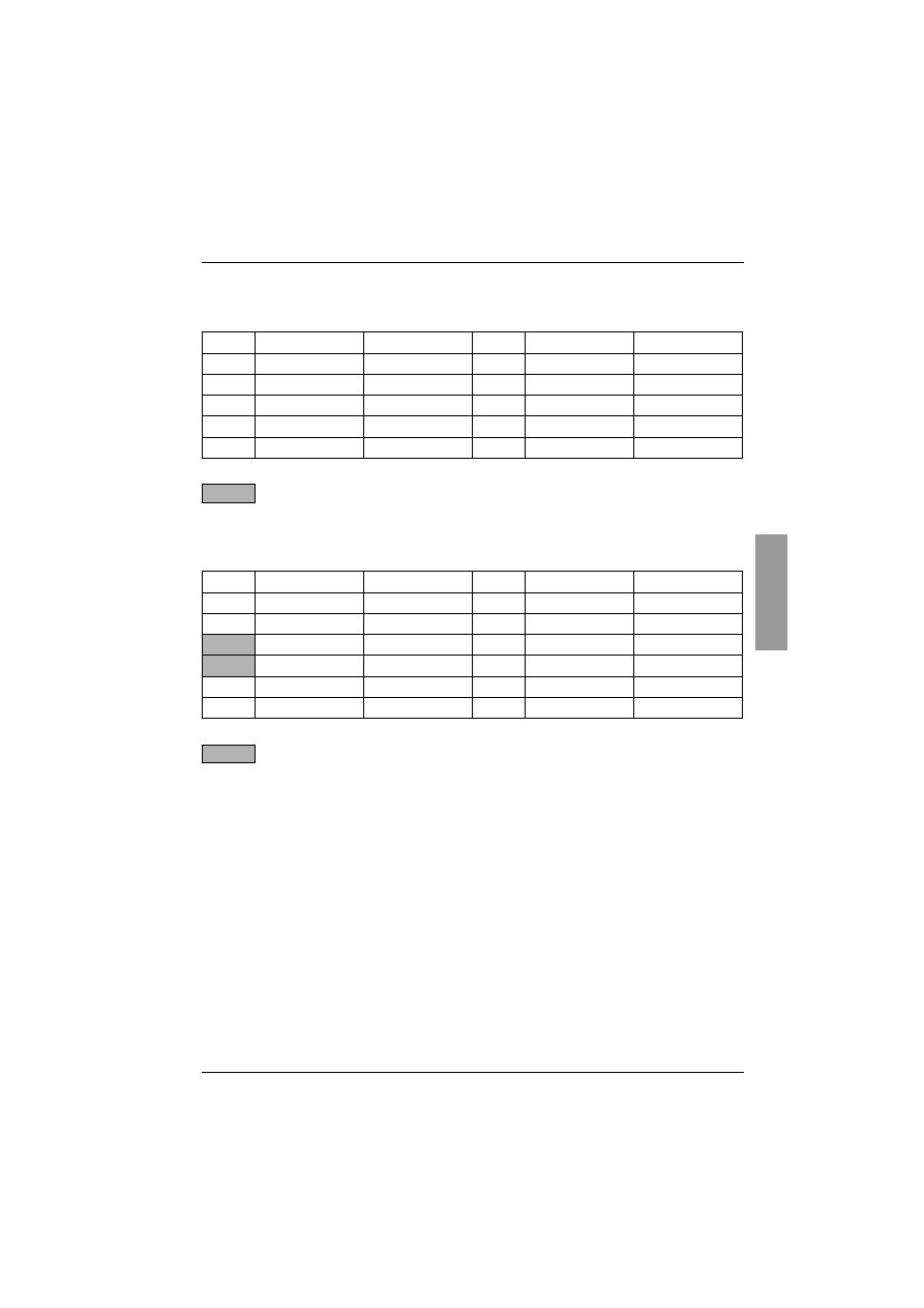
163
ENGLISH
Configuration/Settings tables
Advanced settings menu
d
d
d
dr
r
r
rC
C
C
C
I/O menu
I
I
I
IO
O
O
O
(1) -ATS 48 •••Q: 400 V
-ATS 48•••Y: 460 V
Code
Factory setting
Customer setting
Code
Factory setting
Customer setting
t
t
t
tL
L
L
LI
I
I
I
OFF
L
L
L
LS
S
S
SC
C
C
C
50%
b
b
b
bS
S
S
St
t
t
t
OFF
t
t
t
tI
I
I
IG
G
G
G
40%
d
d
d
dL
L
L
Lt
t
t
t
OFF
C
C
C
CS
S
S
SC
C
C
C
OFF
S
S
S
SS
S
S
St
t
t
t
OFF
U
U
U
UL
L
L
Ln
n
n
n
(1)
C
C
C
CL
L
L
LP
P
P
P
On
F
F
F
Fr
r
r
rC
C
C
C
AUt
The parameters in shaded boxes appear if the corresponding functions have been configured.
Code
Factory setting
Customer setting
Code
Factory setting
Customer setting
L
L
L
LI
I
I
I3
3
3
3
LIA
r
r
r
r1
1
1
1
rII
L
L
L
LI
I
I
I4
4
4
4
LIL
r
r
r
r3
3
3
3
rn1
I
I
I
IP
P
P
Pr
r
r
r
0%
A
A
A
AO
O
O
O
OCr
t
t
t
tP
P
P
Pr
r
r
r
5 s
O
O
O
O
4
4
4
4
020
L
L
L
LO
O
O
O1
1
1
1
tA1
A
A
A
AS
S
S
SC
C
C
C
200
L
L
L
LO
O
O
O2
2
2
2
rn1
The parameters in shaded boxes appear if the corresponding functions have been configured.

ENGLISH
164
Configuration/Settings tables
2nd motor parameters menu S
S
S
St
t
t
t2
2
2
2
This menu is only visible if a logic input is assigned to the function for activating a second set of motor
parameters (LIS) in the I/O menu.
Communication menu C
C
C
CO
O
O
OP
P
P
P
(1) Depends on the starter rating.
Code
Factory setting
Customer setting
Code
Factory setting
Customer setting
I
I
I
In
n
n
n2
2
2
2
(1)
d
d
d
dE
E
E
E2
2
2
2
15 s
I
I
I
IL
L
L
L2
2
2
2
400%
E
E
E
Ed
d
d
d2
2
2
2
20%
A
A
A
AC
C
C
C2
2
2
2
15 s
t
t
t
tL
L
L
L2
2
2
2
OFF
t
t
t
t9
9
9
92
2
2
2
20%
t
t
t
tI
I
I
I2
2
2
2
40%
Code
Factory setting
Customer setting
Code
Factory setting
Customer setting
A
A
A
Ad
d
d
dd
d
d
d
0
t
t
t
tL
L
L
LP
P
P
P
10 s
t
t
t
tb
b
b
br
r
r
r
19.2 kbps
P
P
P
PC
C
C
Ct
t
t
t
OFF
F
F
F
FO
O
O
Or
r
r
r
8n1

165
ENGLISH

VVDED301066
029821
W9 1494409 01 11 A01
2001-07
Document Outline
- Altistart 48 - user's manual
- Contents
- Steps for setting up the starter
- Factory con.guration
- Preliminary recommendations
- Technical speci.cations
- Operating recommendations
- Starter-motor combinations
- Dimensions
- Mounting recommendations
- Mounting in a wall-.xing or .oor-standing enclosure
- Power terminals
- Control terminals
- Wiring/RUN - STOP commands
- Application diagram
- Thermal protection
- Display unit and programming
- Remote terminal option
- Settings menu (Set)
- Protection menu (PrO)
- Advanced settings menu (drC)
- I/O menu (IO)
- 2nd motor parameters menu (St2)
- Communication menu (COP)
- Parameter displayed menu (SUP)
- Compability table
- Maintenance
- Faults - causes - remedies
- Con.guration/Settings tables
Wyszukiwarka
Podobne podstrony:
07 Altivar28 E user manual
07 Altivar38 user manual comm
07 Altivar68 user manual
07 Altistart48 comm bus user manual
cas test platform user manual
CARPROG Opel ECU programmer user manual
elm327 interface viecar obd2 bluetooth scanner user manual
autel power scan ps100 user manual
Chartplanner user manual
INPA User manual
all100 user manual
CARPROG user manual
FX2N 485 BD User's Manual JY992 Nieznany
mb sbc tool user manual
więcej podobnych podstron