Date:
Rev:
Sign:
2006-05-22
E
GS/OA
JOWA 3SEP OWS
OILY WATER SEPARATOR
Standard
K:\1-NYA K\1-JOWA PRODUKTER\3SEP\Manual
1/41
JOWA OILY WATER SEPARATOR
JOWA 3SEP OWS
ALL MODELS: 1.0, 2.5, 5.0, 10.0m3/h
STANDARD
OPERATING INSTRUCTIONS AND
TECHNICAL MANUAL
Daily Operating Instructions for JOWA OWS
Before Start, ensure the user is authorised to operate the equipment.
To Start Operation
1.
Check Valves on Inlet P
ipe.
2.
Check Valves on Outlet Pipe.
3.
Check Valves on Jowa OW
S.
Closed Valves:V11, V13, V14, V15, V16, V17, V18, V19, V30.
Open Valves:V10, V12, V20.
4.
Check Air Supply.
5.
Switch on Power Supply.
6.
Turn Switch to Auto.
7.
When pum
p running, check flow on sam
ple outlet from
bilge-alarm
.
To Stop Operation
1.
Turn Switch
from
Auto to 0
2.
Switch off Power Supply.
3.
Close V20.

JOWA 3SEP OWS
OILY WATER SEPARATOR
Standard
K:\1-NYA K\1-JOWA PRODUKTER\3SEP\Manual
2/41
Table of Contents
1.0
Introduction............................................................................................ 4
1.1 General ............................................................................................................. 4
1.2 System
Overview.............................................................................................. 5
1.3
Guarantee and service...................................................................................... 5
1.4
Note on recycling. ............................................................................................ 6
2.0
Technical Specification......................................................................... 7
3.0
Installation.............................................................................................. 8
3.1 Delivery ............................................................................................................ 8
3.2
Placement of the skid........................................................................................ 8
3.3 Pipe
Connections .............................................................................................. 9
3.4 Separator
Pump ................................................................................................ 9
3.5 Electric
Connections....................................................................................... 10
3.6
Air Supply Pipes and Connections ................................................................. 11
3.7
Filter Media JOWA F - 200 C ........................................................................ 11
3.8
Quantity of Filter Media ................................................................................. 12
3.8.1
Filling the Tanks T2, T3 with Filter Media............................................ 12
3.9
Initial Start-up Checklist ................................................................................ 12
4.0
System Function.................................................................................. 13
4.1 Normal Flow Through the 3SEP OWS (See Flow Diagram)......................... 13
4.2
Manual Shut-off Valve Positions ................................................................... 14
4.3
Oil Release from 3SEP OWS (See Flow Diagram) ....................................... 15
4.3.1
High Level Start Switch ......................................................................... 15
4.3.2
Low Level Stop Switch .......................................................................... 15
4.3.3
Dry Running Protection.......................................................................... 15
4.3.4 Prime
Water............................................................................................ 15
4.4
Optional features on the 3SEP OWS.............................................................. 16
4.4.1
Bilge Clean Mode (Optional) ................................................................. 16
4.4.2
Transfer Mode (optional) ....................................................................... 16
4.4.3
3SEP OWS with JOWA Emulsion Breaking Unit EBU (Optional) ...... 17
5.0
Operation.............................................................................................. 18
5.1 General ........................................................................................................... 18
5.2
Start/Stop the 3SEP OWS .............................................................................. 18
5.2.1
Start/Stop Manual Mode......................................................................... 18
5.2.2
Start/Stop Auto Mode............................................................................. 18
5.2.3
Start/Stop Bilge Clean Mode (optional) ................................................. 19
5.2.4
Start/Stop Transfer Mode (optional) ...................................................... 19
5.3
The PLC User Interface.................................................................................. 19
5.3.1
Menu Display Tree ................................................................................. 20
5.3.2
Menu Display Tree Explanation............................................................. 24
5.3.3
When there is an alarm. .......................................................................... 25
5.4
The Oil Content Meter.................................................................................... 25
5.5
The Pneumatic Solenoid Control Valves ....................................................... 25

JOWA 3SEP OWS
OILY WATER SEPARATOR
Standard
K:\1-NYA K\1-JOWA PRODUKTER\3SEP\Manual
3/41
5.6
Oil Sensor CT03 ............................................................................................. 25
6.0
Maintenance ......................................................................................... 26
6.1
Back flushing Procedure for Filter Tanks T2, T3.......................................... 26
6.2
Changing JOWA F - 200 C Filter Media in Filter Tanks T2, T3. .................. 27
6.2.1
Removing the Filter Media..................................................................... 27
6.2.2
Filling the Tanks T2, T3 with Filter Media............................................ 27
6.3
Checking the Anode Protection...................................................................... 28
6.3.1
Position of Anodes in the Tanks............................................................ 28
6.2
Regular Maintenance Timetable..................................................................... 29
6.2.1 Every
day................................................................................................ 29
6.2.2 Every
week ............................................................................................. 29
6.2.3 Every
month ........................................................................................... 29
6.2.4
Every six months .................................................................................... 29
6.2.5
Every 12 months..................................................................................... 29
7.0
Trouble Shooting ................................................................................. 30
7.1 General ........................................................................................................... 30
7.2 Operation
Errors ............................................................................................. 30
8.0
Flow Diagram (P & I)............................................................................ 32
9.0
Mechanical Drawings .......................................................................... 33
10.0
Electrical Drawings and Pneumatic Drawings .................................. 34
11.0
Oil Content Meter Operating Manual ................................................. 35
12.0
1.0m3/h and 2.5m3/h Pump Operating Manual ................................. 36
13.0
5.0m3/h Pump Operating Manual ....................................................... 37
14.0
10.0m3/h Pump Operating Manual ..................................................... 38
15.0
Oil Sensor Operating Manual ............................................................. 39
16.0
Spare/ Consumables Parts List .......................................................... 40
17.0
Approval Certificates........................................................................... 41

JOWA 3SEP OWS
OILY WATER SEPARATOR
Standard
K:\1-NYA K\1-JOWA PRODUKTER\3SEP\Manual
4/41
1.0 Introduction
The 3SEP OWS is an oily bilge water separation system designed to separate
free/emulsified oil from the bilge water and check that the oil residues in the
treated water do not exceed 15ppm before discharge overboard. The 3SEP
OWS complies with IMO Resolution MEPC 107(49). According to MARPOL
73/78 all vessels above 400 DWT require an approved bilge water separator
and alarm.
The system is available in four different capacities;
1.0m3/h, 2.5 m3/h, 5.0 m3/h and 10.0 m3/h. This manual contains the
instructions for operating all four models.
The treated water released by the 3SEP OWS contains not more than 15-
ppm oil in water. The system has been designed to meet the
requirements prescribed by IMO MEPC 107 (49).
For bilges with heavily emulsified oil in the bilge water a 3SEP OWS coupled to
a JOWA EBU (Emulsion Breaking Unit) offers the best solution and ensures
treated water under 5ppm. The 3SEP OWS is supplied standard with the
necessary inlet for connecting a JOWA EBU. For additional information about
the EBU system contact JOWA.
1.1 General
To obtain all the advantages from operating a 3SEP OWS ensure that all users
have adequate education for the equipment, ensure that the installation is
correct and ensure that the 3SEP OWS is maintained and operated in
accordance with the instructions in this manual. The correct function of the
equipment cannot be guaranteed if the user fails to follow these instructions.
We reserve the right to make changes to the 3SEP OWS without previous
notice.
Before installation and start-up read this manual carefully.
Supplier and manufacturer:
JOWA AB
Tulebo 865
S-428 34 Kållered , Göteborg
Sweden
Phone:
+46-31 726 54 00
Fax:
+46-31 795 45 40

JOWA 3SEP OWS
OILY WATER SEPARATOR
Standard
K:\1-NYA K\1-JOWA PRODUKTER\3SEP\Manual
5/41
1.2 System
Overview.
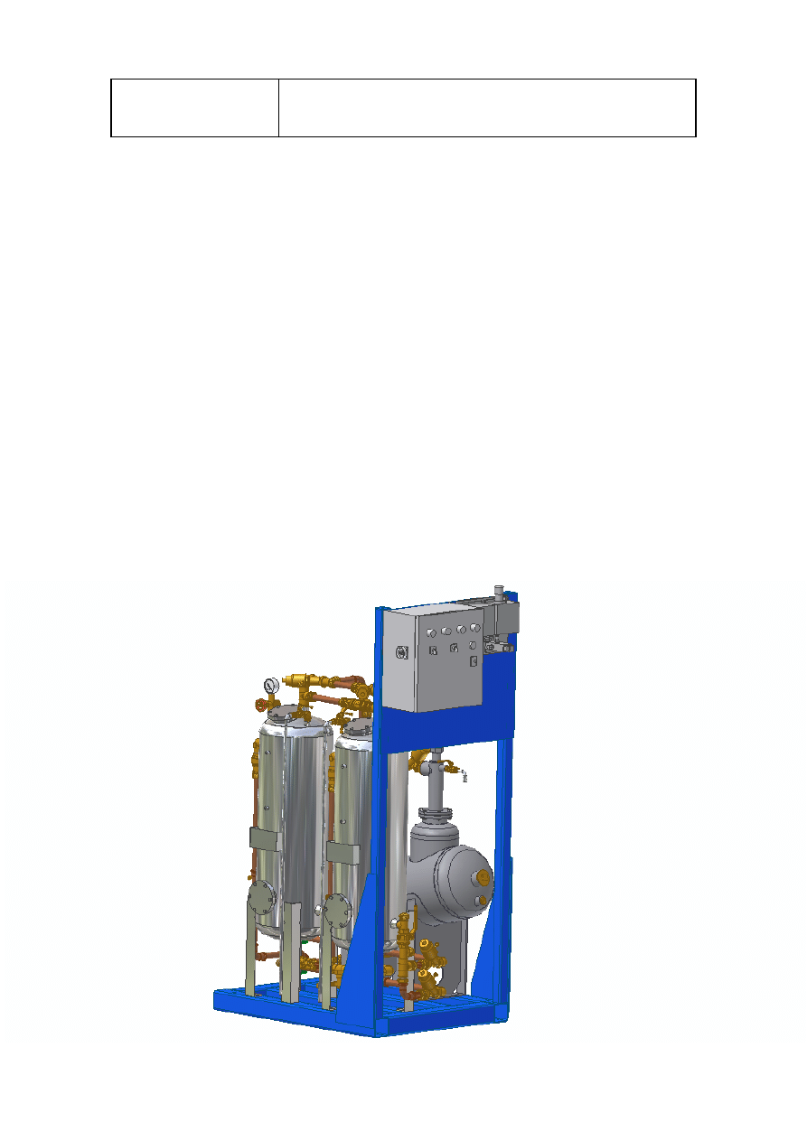
The 3SEP OWS is designed for a continuous flow with automatic operation, the
system does not require any chemicals. The following text gives an overview of
the 3SEP OWS separation process and the 3SEP OWS general arrangement.
The first stage removes the free oil by gravity. An adjustable oil sensor controls
the pneumatic valve for automatic oil release to the sludge tank or any other
dedicated tank. The adjustable oil sensor makes it possible to minimise the
amount of treatable water released to the sludge tank.
In the second stage emulsified oil is removed in the two filter tanks and the ppm
value is monitored continuously by an oil content meter before the treated water
is discharged overboard.
The collected free oil on top of each filter tank is released automatically to the
sludge tank at a preset interval. When a 15 ppm alarm occurs, the 3SEP OWS
will automatically close the overboard line and re-circulate the treatable water to
the bilge. When the contamination falls below 15 ppm the valve for overboard
release will open again without human intervention.
The system is designed as a compact skid assembly with all connection points
collected, for easy “Plug n’ Play” installation. When the unit reaches the
customer the only remaining thing to do is to connect water inlets/outlets, the
electrical power supply and air connection, facilitating quick and easy
installation onboard.
Before leaving our workshop each unit has to pass a quality-test, where
all functions are tested and checked.
All equipment has the highest quality; the tanks are made of acid proof stainless
steel, AISI 316L. Our pumps are supplied by internationally recognised brands.
Spare parts are easily available from one of our offices or representatives
worldwide.
1.3
Guarantee and service.
The JOWA 3SEP OWS is covered by a guarantee period. Guarantee claims
can be made according to JOWA’s Guarantee claim procedure. The JOWA
3SEP OWS contains components with no user serviceable parts which are
sealed. Breaking the seals placed on these components automatically voids the
warranty. Contact JOWA for assistance.
Service should only be carried out by an authorised JOWA service engineer.

JOWA 3SEP OWS
OILY WATER SEPARATOR
Standard
K:\1-NYA K\1-JOWA PRODUKTER\3SEP\Manual
6/41
1.4
Note on recycling.
In the design and manufacture of the JOWA 3SEP OWS all Efforts have been
made to use components that can be recycled. This product or the parts of it
must be disposed of in an environmentally sound manner. Use the local public
or private waste collection service

JOWA 3SEP OWS
OILY WATER SEPARATOR
Standard
K:\1-NYA K\1-JOWA PRODUKTER\3SEP\Manual
7/41
2.0 Technical
Specification
This chapter contains a quick reference table with the main technical
specifications for the 3SEP OWS.

2 Specifications
2.1 Technical data for JOWA 3Sep OWS
Type:
3Sep OWS-1
3Sep OWS-2.5 3Sep OWS-5
3Sep OWS-10
Capacity:
1 m³/h
2.5 m³/h
5 m³/h
10 m³/h
Influent: Bilge
water
Effluent oil
content.
< 15 ppm acc. IMO MEPC 107(49)
Ambient
temperature:
5 - 55
qC
Operation
Pressure:
Normal 0 – 2 Bar, Max 4 Bar
Volume (total):
225 L
450 L
900 L
2 000 L
Weight (total):
excl. Filter mtrl
& pump
225 kg (dry)
450 (wet)
380 kg (dry)
830 kg (wet)
520 kg (dry)
1420 kg (wet)
850 kg (dry)
2850 kg (wet)
Total power
consumption:
1 kW
1 kW
2 kW
3 kW
Air supply:
4 – 6 Bar
Alarms:
1. Common Alarm
2. >15ppm
Tank material:
AISI 316L
Gaskets: Nitrile
Tank volumes:
3 x 75 L
3 x 150 L
3 x 300 L
1x500L,2x750L
Filter media:
JOWA F200
Filter media
quantity:
50 kg
100 kg
200 kg
500 kg
Type Approval
Type approval by DNV. Certificate No. P-11800
Safety Valve:
Durgo 4 bar
GT-77 DN20
GT-77 DN20
4155 DN25
4155 DN32
Bilge Pump
Type: Mono
Screw
Pump Cgg
Mono Screw
Pump Cgh
Axflow Pump
OX1
Axflow Pump
CB 041
Flow rate:
1 m³/h
2.5 m³/h
5 m³/h
10m³/h
Weight:
21 kg
21 kg
53 kg
82 kg
Suction:
Max. 4.5 m lift capacity
Electrical
data
Voltage:
380 – 440 VAC
Frequency:
50 / 60 Hz
Power
consumption:
0.55 / 0.63 kW
1.6 / 1.55 A
0.55 / 0.63 kW
1.6 / 1.55 A
1.5 / 1.7 kW
3.4 / 3.3 A
2.2 / 2.6 kW
4.7 / 4.4 A
R.P.M.
910 / 1100
1240/1500
1380 / 1692
1410 / 1716
Protection class: IP55
Thermal
insulation class:
F

15 PPM Bilge
Alarm
Type:
RTE/DECKMA
Piping
Connections:
Male threads BSP as Standard
Flanged (DIN or JIS) as Option
Oily bilge water
inlet:
1” - DN 25
1” - DN 25
1 ½” – DN40
1 ½” – DN40
Oil release outlet
(to sludge tank):
1” – DN 25
1” – DN 25
1 ½” – DN40
1 ½” – DN40
Back wash water
inlet:
1” – DN 25
1” – DN 25
1” – DN25
1” – DN25
Water outlet
(overboard)
1” – DN 25
1” – DN 25
1 ½” – DN40
1 ½” – DN40
Drain and Re-
circulate water
(to bilge)
1” – DN 25
1” – DN 25
1 ½” – DN40
1 ½” – DN40
Outlet to JOWA
EBU
1” – DN 25
1” – DN 25
1 ½” – DN40
1 ½” – DN40

JOWA 3SEP OWS
OILY WATER SEPARATOR
Standard
K:\1-NYA K\1-JOWA PRODUKTER\3SEP\Manual
8/41
3.0 Installation
This chapter contains step-by-step information detailing how the 3SEP OWS is
installed. At the end of the chapter is a quick reference check list to aid in start-
up after installation or service.
3.1 Delivery
The 3SEP OWS is delivered complete with all valves, pipes, necessary fittings
and an oil content meter mounted on a single skid ready for installation
onboard.
The unit has passed a work-shop tested before delivery.
3.2
Placement of the skid
The 3SEP OWS skid should be placed on a plane surface and welded or bolted
using the pre drilled holes in the skid. When installing the unit it is important to
leave a minimum of 500mm working space in front of the unit (see mechanical
drawings).

JOWA 3SEP OWS
OILY WATER SEPARATOR
Standard
K:\1-NYA K\1-JOWA PRODUKTER\3SEP\Manual
9/41
3.3 Pipe
Connections
All connection points are collected together for easy “Plug n’ Play” installation:
Capacity
1,0m3/h 2,5m3/h 5,0m3/h 10,0m3/h
Piping
Connections:
Male threads BSP as Standard
Flanged (DIN, ANSI or JIS) as Option
Oily bilge water
inlet:
1” - DN 25
1” - DN 25
1 ½” – DN40
1 ½” – DN40
Oil release
outlet (to
sludge tank):
1” – DN 25
1” – DN 25
1 ½” – DN40
1 ½” – DN40
Back flush
water inlet:
1” – DN 25
1” – DN 25
1” – DN25
1” – DN25
Water outlet
(overboard)
1” – DN 25
1” – DN 25
1 ½” – DN40
1 ½” – DN40
Drain and Re-
circulate water
(to bilge)
1” – DN 25
1” – DN 25
1 ½” – DN40
1 ½” – DN40
Outlet to
JOWA EBU
(Optional)
1” – DN 25
1” – DN 25
1 ½” – DN40
1 ½” – DN40
3.4 Separator
Pump
The pump is delivered as a separate unit for installation as close to the bilge
water tank as possible to avoid suction problems. Use piping with the same
dimension as the pump is designed for. Refer to the flow diagram chapter and
the recommended installation drawing.
Use pipe connections according to specification below.
Separator
Size
Dimension
1 m³/h and 2,5 m³/h
1" ( DN 25 )
5 m³/h and 10 m³/h
1½” ( DN 40 )

JOWA 3SEP OWS
OILY WATER SEPARATOR
Standard
K:\1-NYA K\1-JOWA PRODUKTER\3SEP\Manual
10/41
3.5 Electric
Connections
The electrical equipment of the separator is ready for installation when
delivered. The power supply should be three phase 380-480 VAC 50/60Hz.
Other power supplies on request. See the electrical drawings for further
information.
The mains supply should have a 10A fuse for separators up to 5m3/h and a 16A
fuse for 10m3/h separators. Connect the main cable to terminal 1,2,3 in the
main control box. Connect the pump motor cable directly over the current relay
2,4,6 in the main control box.
Cable for pump, mains supply and 3 pole circuit breaker are not included in the
delivery.
Voltage:
3 phase 380-400-415-440-460-480 VAC 50/60 Hz.
JOWA 3SEP OWS
OILY WATER SEPARATOR
Standard
K:\1-NYA K\1-JOWA PRODUKTER\3SEP\Manual
11/41
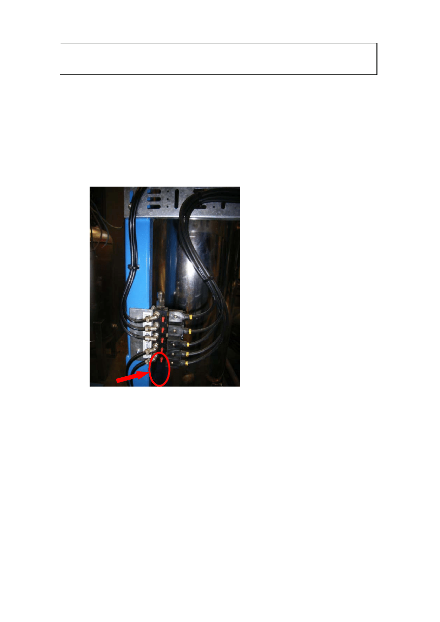
3.6
Air Supply Pipes and Connections
Air supply is connected to the pneumatic solenoid control valves. The solenoid
block is located just below the control cabinet. The counter connector is
supplied for attaching of 8 mm Cu-pipe. The pressure should be 4-6 bar dry
instrument air.
Fig 3.6.1 Air Inlet to Solenoids.
3.7
Filter Media JOWA F - 200 C
The filter media, JOWA F – 200 C, for the filter tanks T2 and T3 is delivered
fully prepared in sacks of 25 kilos each. The Separator is always empty by
delivery. Filter media for the first filling is included in the delivery.
NOTE! For guaranteed function we recommend the JOWA F - 200 C filter
media.

JOWA 3SEP OWS
OILY WATER SEPARATOR
Standard
K:\1-NYA K\1-JOWA PRODUKTER\3SEP\Manual
12/41
3.8
Quantity of Filter Media
Model
Tank Size Quantity (2 Tanks)
1.0m3/h
75 l
50 kilo
2,5m3/h
150l
100kilo
5.0m3/h
300l
200kilo
10.0m3/h
750l 500kilo
3.8.1 Filling the Tanks T2, T3 with Filter Media
NOTE! Before filling check that the internal strainers are carefully
fastened.
Fill the tanks T2 and T3 through the upper hatches to 60-70 % of the tank
volume, approximately 10-15 centimetres below the upper strainers. When the
tanks are filled with filter media mount the upper hatches and back flush each
filter one by one for at least 10 minutes until clean fresh water is coming through
the sample valves V18 and V19 (See Chapter 6.1 for detailed back flushing
instructions). The amount of back flushed water should be at least 3 times the
volumes of the filters. We recommend back flushing with fresh water at a
pressure of no more than 6 bar. Maintain low water pressure and speed
during back flushing to avoid losing filter media from V18 and V19. Throttle
V15 and V16 to control water speed and pressure during back flushing.
3.9
Initial Start-up Checklist
Use the following start-up checklist after installation or service.
running dry.
normal operation (See System function chapter)
particles are removed from the new filter media (See Maintenance
Chapter).

JOWA 3SEP OWS
OILY WATER SEPARATOR
Standard
K:\1-NYA K\1-JOWA PRODUKTER\3SEP\Manual
13/41
4.0 System
Function.
This chapter provides a detailed description of the unique functions of the 3SEP
OWS. The material provided in this chapter gives the operator the possibility to
gain an excellent understanding into how and why the 3SEP OWS performs its
functions. It is intended that the information in this chapter may be used to help
the operator optimise the 3SEP OWS performance to his or her specific bilge
requirements.
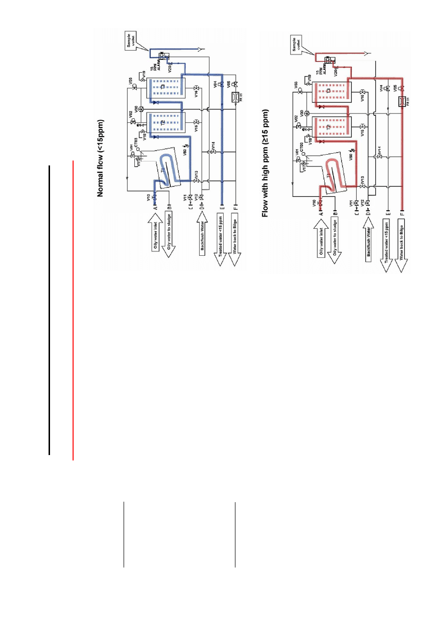
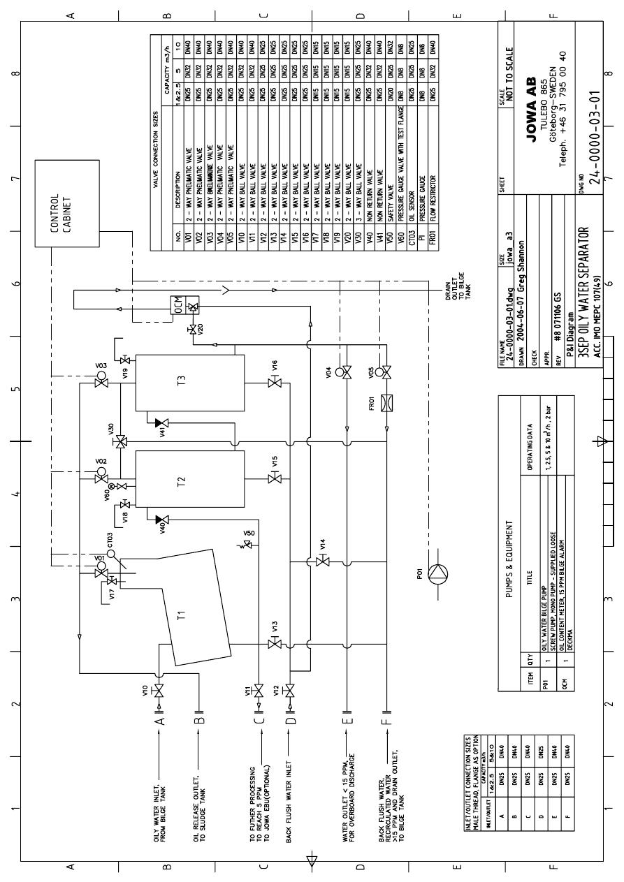
4.1 Normal Flow Through the 3SEP OWS (See Flow Diagram)
Normal flow through the 3SEP OWS.
The separator consists of three (3) tanks connected in series, tanks T1-T3, and
the oil content meter. Tank T1 utilises specific gravity to separate and release
free oil. Tanks T2 and T3 are filters utilising the filter media JOWA F - 200 C to
remove the majority of the remaining emulsified oil. Finally the oil content of the
treated water is checked by the oil content meter before it is discharged
overboard.
The bilge water is initially pumped into the top of T1 thru valve V10 where most
of the free oil is gathered in the release pipe. When the oil senor CT03 detects
oil it is released through the pneumatically controlled valve V01 and is delivered
to the concentrated sludge tank.
The partly treated water is then pumped out of the bottom of T1 through the two
filter tanks T2 and T3 connected in series. The pneumatically controlled valves
V02 and V03 release the free oil at the top of T2 and T3 to the concentrated
sludge tank.
At the outlet of tank T3 the oil content in the treated water is checked by the oil
content meter. The valve V20 shall be in open position. The treated water flows
through the pneumatically controlled valve V04 for overboard discharge.
If the oil content of the flow coming from the outlet the 3SEP OWS exceeds
15ppm the pneumatically controlled valve V04 closes and the pneumatically
controlled valve V05 opens, re-circulating the discharge from the 3SEP OWS
to the bilge. When the oil content detected by the oil content meter falls below
15ppm again V05 will close, V04 will open and overboard discharge will
resume.

JOWA 3SEP OWS
OILY WATER SEPARATOR
Standard
K:\1-NYA K\1-JOWA PRODUKTER\3SEP\Manual
14/41
If during re-circulating there is no flow through the sample outlet line of the bilge
alarm adjust flow restrictor FR01.
The recirculation cycle occurs for 20 minutes and is adjustable (See Chapter 5).
If the treated water remains above 15ppm at the resumption of normal flow after
the recirculation cycle, the 3SEP OWS will stop and an alarm will occur. The
3SEP OWS can be back flushed and restarted. See Chapter 6.1 for back
flushing instructions.
4.2
Manual Shut-off Valve Positions
The following tables indicate which of the manually controlled valves are open
and closed during normal operation of the 3SEP OWS.
Opened
V10
V20
V12
Closed
V11 (If no EBU)
V13
V14
V15
V16
V17
V18
V19
V30
Partly Closed
FR01

JOWA 3SEP OWS
OILY WATER SEPARATOR
Standard
K:\1-NYA K\1-JOWA PRODUKTER\3SEP\Manual
15/41
4.3
Oil Release from 3SEP OWS (See Flow Diagram)
Oil Release occurs at three points on the JOWA 3SEP OWS; T1, T2 and T3.
The released oil should be delivered to a suitable tank such as the concentrated
sludge tank. The flexibility of the 3SEP OWS oil release system allows a high
degree of control over the oil release.
In the first stage, tank T1, oil release is controlled by an oil sensor, CT03. The
sensitivity of the oil sensor CT03 is operator adjustable in order to minimise the
amount of treatable water released from T1. To adjust the sensitivity of the oil
sensor CT03 see chapter 5.3 and 5.6.
The oil accumulates in the top of T2 and T3 as the partly treated water is
delivered from T1. Oil release from the filter tanks T2 and T3 occurs
automatically. This oil is released by the pneumatically controlled valves V02 on
tank T2 and V03 on tank T3. The time length interval between oil releases for
V02 and V03 is fixed.
Oil is released from V02 every five minutes, for a time period of 20 seconds
(adjustable). Oil is released from V03 every hour for a fixed period of 5 seconds.
When the JOWA 3SEP OWS is started an automatic oil release from V02, and
V03 occurs for a fixed period of 3 seconds. This ensures that the pure oil that
has gathered at the tops of the tanks while the unit has been stationary is now
released.
4.3.1 High Level Start Switch
Automatically starts the 3SEP OWS when the bilge water level is high, using a
level switch located in the bilge tank.
4.3.2 Low Level Stop Switch
Automatically stops the 3SEP OWS when the bilge water level is low, using a
level switch located in the bilge tank..
4.3.3 Dry Running Protection
Protects the 3SEP OWS pump from running dry.
4.3.4 Prime
Water
Automatically primes the 3SEP OWS pump.

JOWA 3SEP OWS
OILY WATER SEPARATOR
Standard
K:\1-NYA K\1-JOWA PRODUKTER\3SEP\Manual
16/41
4.4
Optional features on the 3SEP OWS.
The following are optional features for the 3SEP OWS:
4.4.1 Bilge Clean Mode (Optional)
Bilge clean mode gives the operator the flexibility to run the 3SEP OWS while
docked in the harbour. In bilge clean mode no treated water is released
overboard but constantly re-circulated to the bilge.
In bilge clean mode the flow from the bilge only passes through the first stage
tank T1 and then returns to the bilge tanks. The bilge water is pumped into the
top of T1 thru valve V10 where most of the free oil is gathered on the
coalescence surfaces. When the oil senor CT03 detects oil it is released
through the pneumatically controlled valve V01 and is delivered to the
concentrated sludge tank. The flow then passes through V13 and returns to the
bilge.
Running in bilge clean mode allows the maximum amount of free oil to be
removed from the bilge water before it passes through the filter tanks T2 and
T3, maximising the life of the JOWA F - 200 C filter media.
4.4.2 Transfer Mode (optional)
Some vessels have more than one bilge tank. Transfer mode uses the 3SEP
bilge pump to pump between these different bilge tanks without flow passing
through the 3SEP.
JOWA 3SEP OWS
OILY WATER SEPARATOR
Standard
K:\1-NYA K\1-JOWA PRODUKTER\3SEP\Manual
17/41
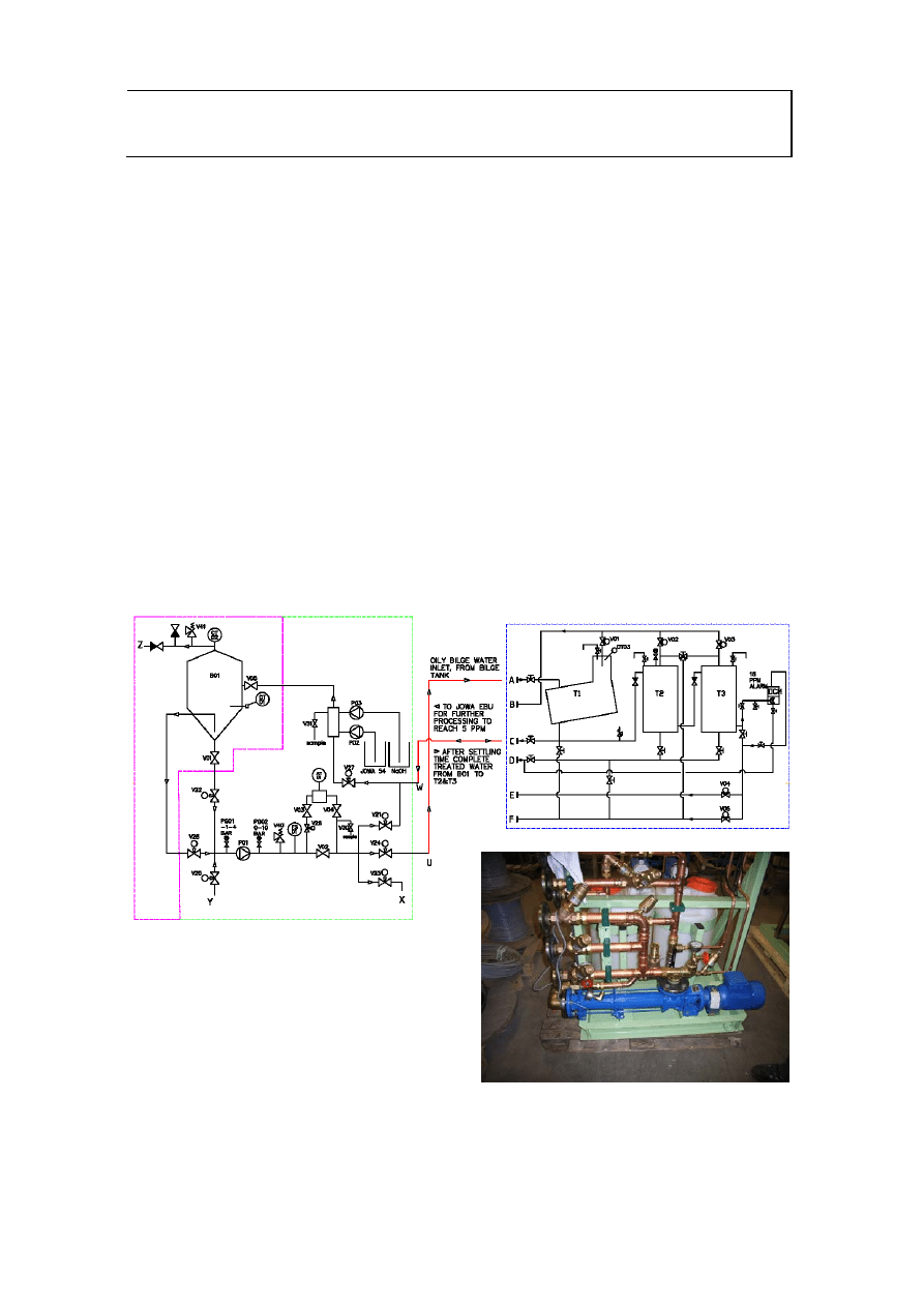
4.4.3 3SEP OWS with JOWA Emulsion Breaking Unit EBU (Optional)
A JOWA EBU system may be coupled to the 3SEP OWS as an extra treatment
stage. The JOWA EBU 3SEP OWS package can achieve treated water with
less than 5ppm oil in water.
It is strongly recommended that the operator consider a 3SEP OWS coupled
with JOWA EBU if the bilge water contains high levels of emulsified oil. The
JOWA EBU is a chemical treatment of the emulsified oil in water. The chemical
is a flocculent that helps the small particles of oil coalesce together and thus
separate by gravity.
The 3SEP OWS skid is ready supplied with the connection for a JOWA EBU
(See Flow Diagram).
The adding a JOWA EBU requires no additional input from the operator other
than to connect the JOWA EBU to the Optional JOWA EBU outlet on the 3SEP
OWS skid.
Fig 4.4 JOWA EBU schematic and picture of EBU pump skid

JOWA 3SEP OWS
OILY WATER SEPARATOR
Standard
K:\1-NYA K\1-JOWA PRODUKTER\3SEP\Manual
18/41
5.0 Operation
This chapter gives the operator detailed information on how the major control
components of the 3SEP OWS are operated and adjusted.
5.1 General
General operation of the 3SEP OWS is facilitated by the PLC user interface and
the switches located on the door of the main control box. All of the electric and
pneumatic control equipment is located on the control cabinet stand at the side
of the 3SEP OWS skid frame. Before delivery all electrical equipment on the
unit is connected and thoroughly work-shop tested.
x All electric equipment is connected to the main control box and the 3SEP
OWS is operated from here. The main power switch, S1, for the 3SEP OWS
is located on the side of the main control box.
x The electronic parts for the oil content meter are located inside the oil content
meter control box.
x The pneumatic solenoids for the pneumatic control valves are located on the
side of the 3SEP OWS skid frame control stand
5.2
Start/Stop the 3SEP OWS
After the actions in section 3.9 ‘Initial Start-up Checklist’ have been completed
the unit can be started and run in normal operation.
5.2.1 Start/Stop Manual Mode
Turn on switch S0, ‘power on’. Turn switch S2 to position 1 for Man mode. The
3SEP OWS will run in auto mode. The 3SEP OWS first runs through a start
routine before normal flow commences. In the start routine oil is released from
all tanks by means of the pneumatically controlled valves V01-V03 opening for
a short period. To stop the 3SEP OWS simply switch S2 to position 0.
5.2.2 Start/Stop Auto Mode
In this mode the 3SEP is started by the high/low level switches located in the
bilge tank described in the previous chapter
JOWA 3SEP OWS
OILY WATER SEPARATOR
Standard
K:\1-NYA K\1-JOWA PRODUKTER\3SEP\Manual
19/41
5.2.3 Start/Stop Bilge Clean Mode (optional)
Turn on switch S0, ‘power on’. Turn switch S2 to position 2 for bilge clean
mode. The 3SEP OWS will run in bilge clean mode. To stop the 3SEP OWS
simply switch S2 to position 0.
5.2.4 Start/Stop Transfer Mode (optional)
Transfer mode can be operated in both auto and manual mode. However, the
operator must exercise caution and see that the manual ball valves between the
bilge tanks are in the correct position for transfer mode function correctly.
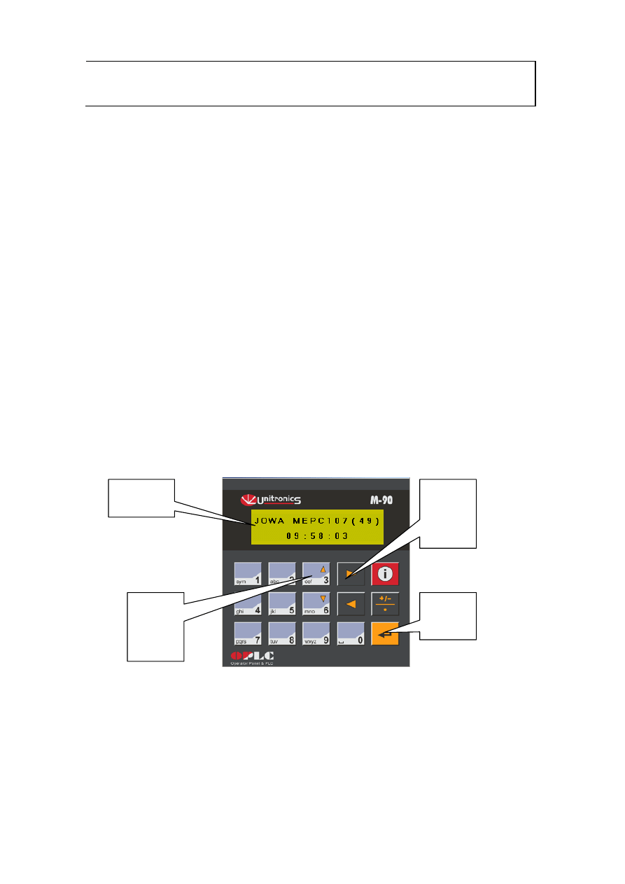
5.3
The PLC User Interface
The PLC user interface facilitates the running and understanding of the 3SEP
OWS. Through the user interface and display on the main control cabinet door
you receive all messages concerning the 3SEP OWS such as operational
status, alarms, and pre-set times.
Fig 5.3 PLC Interface
The user moves up and down through the menu display tree using the
up/down and left/right keys. Information such as time is input using the
number keys. The input value is confirmed by pressing the enter key.
Left/
Right
Keys
Up/
Down
Keys
Enter
Key
Display
Window
JOWA 3SEP OWS
OILY WATER SEPARATOR
Standard
K:\1-NYA K\1-JOWA PRODUKTER\3SEP\Manual
20/41
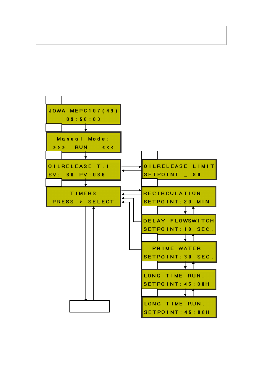
5.3.1 Menu Display Tree
The following schematic shows how the user navigates through the menus in
the 3SEP OWS.
Fig 5.3.1 Menu Display Tree
1.0
2.0
3.0
4.0
4.1
4.2
3.1
4.3
4.4
Next page…
4.5
JOWA 3SEP OWS
OILY WATER SEPARATOR
Standard
K:\1-NYA K\1-JOWA PRODUKTER\3SEP\Manual
21/41
5.3.1 Menu…
All adjustments can be done even when the unit is running.
Alarm displays
When an alarm is activated the system will stop. The display will now show the
reason for the stop.
7.0 High current. Pump motor over load.
Please reset by push button on overload
relay Q01. To start again please push red
Lamp/button on front of control box.
8.0 Flow failure. No indication from flow-
switch when the pump is running. Please
check flow or flow-switch. To start again
please push red Lamp/button on front of
control box.
9.0 Long time high ppm. Re-circulation
time is out. Check bilge alarm. If this is OK
please back flush the filter. To start again
please push red Lamp/button on front of
control box.
10.0 Long time running. The timer for
“long time run” is out. Reset and start
again. Check settings for “long time run.”
5.1
6.0
8.0
7.0
Previous page…
9.0
5.0
JOWA 3SEP OWS
OILY WATER SEPARATOR
Standard
K:\1-NYA K\1-JOWA PRODUKTER\3SEP\Manual
22/41
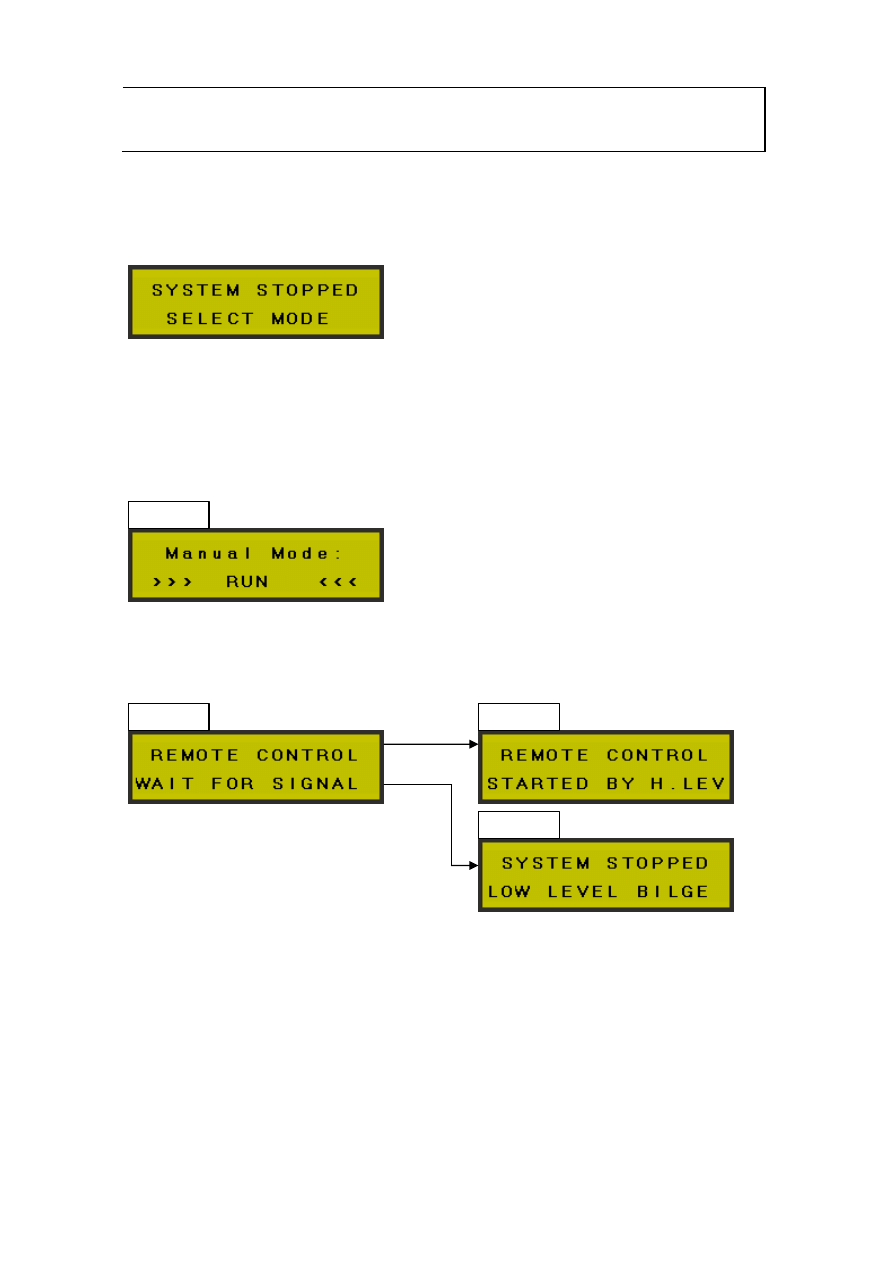
5.3.1 Menu…
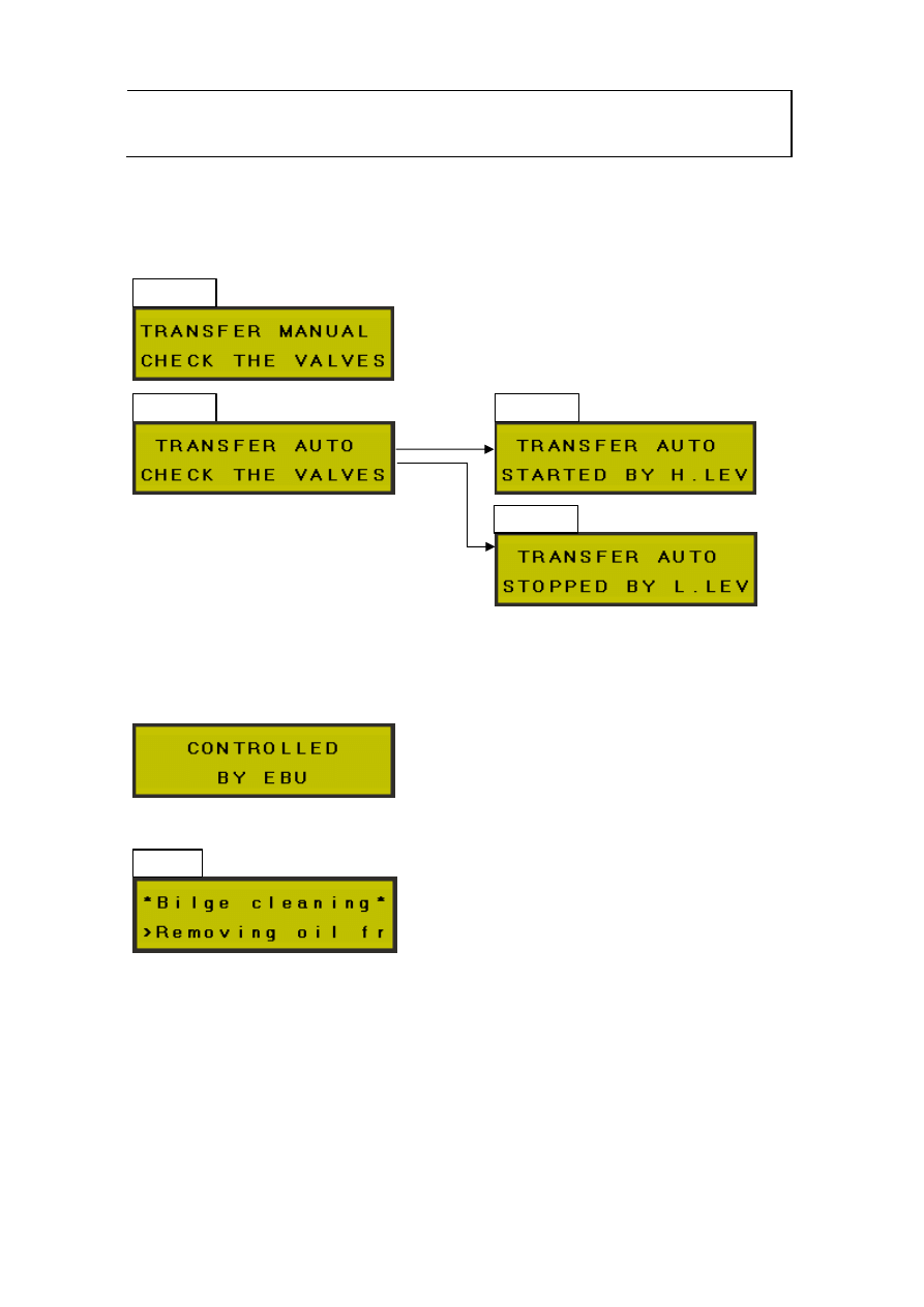
Mode selection.
There are two selection switches. One for the 3SEP and one for transfer
(Option).
3SEP normal set-up is Manual and Auto
The system will running when the switch is in Man. pos.
The system will be controlled by High/Low level (remotely) when the switch is in
Auto pos.
Man
Auto
High lev.
Low lev.
JOWA 3SEP OWS
OILY WATER SEPARATOR
Standard
K:\1-NYA K\1-JOWA PRODUKTER\3SEP\Manual
23/41
Transfer mode.(Option)
Transfer bilge water between two bilge tanks.
EBU mode.(Option)
Controlled by EBU unit. EBU start and stop the 3SEP.
Bilge clean mode.(Option)
Man
Auto
High lev.
Low lev.
Auto

JOWA 3SEP OWS
OILY WATER SEPARATOR
Standard
K:\1-NYA K\1-JOWA PRODUKTER\3SEP\Manual
24/41
5.3.2 Menu Display Tree Explanation
Menu Sub-
Menu
Function/Description
1.0 -
Start-up display.
User sets the time here
2.0 -
3SEP Operational Status.
Displays Run or Stop.
3.0
Tank T1 oil release Display.
The SV value is set by the user in sub menu 3.1, and the value PV
is the real time value sensed by CT03. The user presses enter to go
to 3.1 where SV is input
3.1
This set-point is not active in “bilge clean mode”.
The desired SV Oil Release value 0-100 (See 5.6) is input here.
Press enter to exit sub menu 3.1
4.0
Timers Menu. Press right arrow key to enter sub menus
4.1 Adjust re-circulation time here, factory value is 20mins, (see
Chapter 4, Sect 4.1). Navigate back to menu 4.0 or down to sub
menu 4.2 using the up/down left/right keys
4.2
Set-value for flow-switch timer
4.3
Set-value for “prime water” timer
4.4
Set-value for “long time running” timer
4.5
Set-value for “oil release tank 2” timer
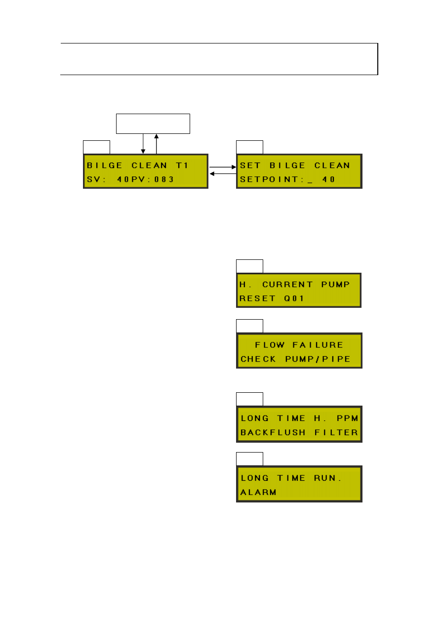
5.0
Optional extra. Bilge clean mode. This mode allow you to remove
oil from bilge when you can’t discharge overboard. The water will go
back to bilge and the oil will go to sludge tank.
5.1
This set-point will only be active in “bilge clean mode”.
The desired SV Oil Release value 0-100 (See 5.6) is input here.
Press enter to exit sub menu 5.1
6.0
This display is active in “bilge clean mode”.
When the system is running in “bilge clean mode” there will be a
circulating text on second row in the display.
“>>REMOVING OIL FROM BILGE TANK>>”
5.1
(Via 6.0)
When the system is in “bilge clean mode” you can access the
adjustment for oil release in tank 1 (5.1) by pushing 7 and 9. After
adjustment you can go back with 1 and 7.
7.0
Alarm display for “High current pump”.
8.0
Alarm display for “Flow failure”.
9.0
Alarm display for “Long time high ppm”.
10.0
Alarm display for “Long time running”.

JOWA 3SEP OWS
OILY WATER SEPARATOR
Standard
K:\1-NYA K\1-JOWA PRODUKTER\3SEP\Manual
25/41
5.3.3 When there is an alarm.
The different alarm conditions are listed in section 5.3.1. A Failure message
indicates the problem. When the failure is corrected the alarm can be reset by
pressing the red reset button.
5.4
The Oil Content Meter
The oil content meter is located on the control cabinet stand on the 3SEP OWS
skid. The oil content meter door displays the oil content in PPM in the water
being discharged from the 3SEP OWS. The alarm limit for the oil content is
adjustable between 0 - 15 PPM. The oil content in the water is measured by the
sensor unit located to the right of the oil meter electric control box. If there is no
flow through the oil content meter the reading will be corrupt and the oil content
meter will register an alarm. A complete Technical and Operation manual for the
Oil Content Senor will be included in the oil content meter chapter of this
manual.
5.5
The Pneumatic Solenoid Control Valves
The pneumatic solenoid control valves control the valves V01 to V05. Each
pneumatic solenoid control valve is marked with the valve position number. The
air pressure to the solenoid control valves must be 4-6 BAR dry instrument air
to get a proper function and performance of the valves.
5.6
Oil Sensor CT03
The oil sensor, CT03, measures the capacitance between the sensor rod and
the pipe wall. The index of the oil sensor varies from 2 to 100, where 2 is air and
100 is water (oil has a value of 2-20). The factory set point value is 80. The set
point of CT03 may be adjusted by the operator to suit the amount of free oil in
the bilge water. For example a lower set point value on CT03 may suit a bilge
with high amounts of free oil. Lowering the set point value has the advantage of
decreasing the amount of water released to the concentrated sludge tank.
However lowering the value may also shorten the lifespan of the JOWA F – 200
C filter media, as it must absorb more oil. Conversely, raising the value will
result in more water being released to the concentrated sludge tank but a longer
filter media lifespan. The sensor rod has to be cleaned regularly to ensure its
correct function, See chapter 6 for cleaning instructions.

JOWA 3SEP OWS
OILY WATER SEPARATOR
Standard
K:\1-NYA K\1-JOWA PRODUKTER\3SEP\Manual
26/41
6.0 Maintenance
This chapter provides detailed instructions for common maintenance operations
on the 3SEP OWS. A regular maintenance timetable is also included. The
timetable is designed to aid the operator in scheduling minor periodic
maintenance tasks thus avoiding unnecessary breakdowns.
6.1
Back flushing Procedure for Filter Tanks T2, T3.
It is necessary to back flush the filter tanks T3 and T2, in that order:
x After
JOWA F - 200 C is installed at start-up
x The oil content meter gives an alarm indicating an oil content exceeding 15
ppm for a period of extended time or
x After changing the JOWA F - 200 C filter media as part of regular service,
approximately once a week.
Proceed as follows:
1. Switch off the unit, close the valve V10 (and V11 if 3SEP OWS is connected
to a JOWA EBU).
2. Make sure that the pressurised fresh water is available at the valve V12
3. Start the back flushing of filter tank T3 by opening the valve V12 carefully.
4. Open valves V16 and the 3-way valve V30, carefully monitor the pressure.
Do not fully open V30 immediately, open it slowly, allowing the flow to
build pressure slowly. This avoids flushing away the JOWA F - 200 C filter
media from the sample points V18 & V19. It also avoids damage to the
pneumatic and non-return valves from flushing the JOWA F - 200 C filter
media into them.
5. Be sure that V30 is allowing the flow to pass thru T3. You may check this by
observing the outlet pressure at V19
6. Check the water quality through the valve V19.
7. Back flush until the water is clean, usually three times the volume of the filter
is the required amount of water for back flushing (5-10 minutes for each
filter).
8. Close the valves V12 and V16 and V19.
9. Start the back flushing of filter tank T2 by opening the valve V12 and then
valve V15 and the 3-way valve V30. Again, Do not fully open V30
immediately, open it slowly, allowing the flow to build pressure slowly.
10. Be sure that V30 is allowing the flow to pass thru T2. You may check this by
observing the outlet pressure at V18
11. Check the water quality through the valve V18.

JOWA 3SEP OWS
OILY WATER SEPARATOR
Standard
K:\1-NYA K\1-JOWA PRODUKTER\3SEP\Manual
27/41
12. Back flush until the water is clean, usually three times the volume of the filter
is the required amount of water for back flushing (5-10 minutes for each
filter).
13. Close the valves V12 and V15 and V18.
14. Back flushing is complete.
6.2
Changing JOWA F - 200 C Filter Media in Filter Tanks T2, T3.
The filter media must be changed at least every 12-24 months. This section
describes the procedure for changing the filter media.
6.2.1 Removing the Filter Media
NOTE! When removing filter media, make sure that you do not damage internal
filter tank strainers. The strainers are located in the top and bottom of T2 and
T3, see mechanical drawings chapter 9.
x Stop the 3SEP OWS at the main control box, close V10 (and V11 if 3SEP
OWS is connected to a JOWA EBU).
x Open the filter tanks bottom valves V15, V16 and V14 to drain the water from
the filter tanks.
x Open the sample valves V18 and V19 to let air into the top of the tanks.
x Remove the upper hatches and wait until the water flow at the bottom has
stopped.
x Open the lower hatches and empty the tanks of filter media.
Clean the tanks carefully inside and check that the internal strainers are
undamaged and free of carbon and oil. Check the zinc anodes and change
them if more than 70 % of the zinc has corroded.
6.2.2 Filling the Tanks T2, T3 with Filter Media
NOTE! Before filling check that the internal strainers are carefully
fastened and undamaged. Should the strainers be damaged replace them.
See chapter 17 Spare/Consumables Parts List. Fill the tanks T2 and T3 through
the upper hatches to 60-70 % of the tank volume, approximately 10-15
centimetres below the upper strainers. When the tanks are filled with filter
media mount the upper hatches and back flush each filter one by one for at
least 10 minutes until clean fresh water is coming through the sample valves
V18 and V19 (See the previous section of this chapter for detailed back flushing
instructions).
NOTE! For guaranteed function we recommend the JOWA F - 200 C filter
media.

JOWA 3SEP OWS
OILY WATER SEPARATOR
Standard
K:\1-NYA K\1-JOWA PRODUKTER\3SEP\Manual
28/41
6.3
Checking the Anode Protection
The first stage tank, T1 and the filter tanks T2, T3 are made of acid proof
stainless steel AISI 316L. The tanks, pipes and fittings are protected against
corrosion by fixed zinc anodes. The zinc anodes should be checked every six
(6) months. They should be changed if more than 70% of their mass is
corroded
6.3.1 Position of Anodes in the Tanks.
Tank T1:
For all sizes 1.0 – 10.0m3/h the zinc anode is located at the front of the tank in
the lower socket. The front of the tank, T1, can be considered to be under the
main control cabinet
Tanks T2, T3:
75 l tank (1.0m³)
inside lower hatch
150 l tank (2,5-5m³)
inside lower hatch
300 l tank (5m³)
inside lower hatch
750 l tank (10 m³)
inside lower hatch
The location of the anodes are marked with labels.

JOWA 3SEP OWS
OILY WATER SEPARATOR
Standard
K:\1-NYA K\1-JOWA PRODUKTER\3SEP\Manual
29/41
6.2
Regular Maintenance Timetable
6.2.1 Every
day
x Check that the pneumatic solenoids and valves are functioning properly
x Check for leaks of both air and oil/water
6.2.2 Every
week
x Back flush the filter tanks T2 and T3 according to the instructions in 6.1.
x Clean the oil content meter measuring according to the manufacturers
instructions. Refer to the chapter on the operation of the oil content meter
6.2.3 Every
month
x Check the Oil sensor CT03 and adjust according instruction chapter 5.6 if
necessary. Clean the rod of the oil sensor thoroughly by unscrewing and
removing CT03 from T1.
6.2.4 Every six months
x Check the zinc anodes in tanks T1, T2 and T3
x Check the Stator at the pump P01.
6.2.5 Every 12 months
x Change filter material in the filter tanks T2 and T3 and clean the inside of
the tanks.
x Clean tank T1 on the inside. Remove the oil release flange and pipe and
clean the tank thoroughly using high pressure hot water to remove the
oil.

JOWA 3SEP OWS
OILY WATER SEPARATOR
Standard
K:\1-NYA K\1-JOWA PRODUKTER\3SEP\Manual
30/41
7.0 Trouble
Shooting
This chapter provides the operator with a comprehensive trouble-shooting
guide.
7.1 General
Every error in the operation is indicated as an alarm and presented at the
operators display of the PLC.
7.2 Operation
Errors
Error Remedy/Action
The oil content meter
indicates over 15
PPM
The pump, P01, does
not give a flow.
Pressure too high at
the pressure gauge
P01 and the safety
valve V50 opens.
x Back flush the filter tanks T2 and T3.
Replace the JOWA F - 200 C filter media if
necessary
x Check the Stator and replace it if necessary.
Check that the electric motor is receiving
the right voltage.
x Check the pipes are not clogged
x Check the rotation of the pump
x Check that the manual valves in the flow
direction are opened.
x Check that air is connected.
x Run the pneumatic valves manually by
turning the small screws on the solenoid
control valves.
x Check the connectors for the valves for air
leaks.
x Back flush the tanks T2 and T3

JOWA 3SEP OWS
OILY WATER SEPARATOR
Standard
K:\1-NYA K\1-JOWA PRODUKTER\3SEP\Manual
31/41
Error
The pneumatic valves
do not open.
V01 does not close
CT03 reading
incorrectly
Remedy/Action
x Check the air connection (4-6 bar).
x Test run the pneumatic valves manually by
turning the small screws on the solenoid
control valves.
x Check the connectors for the valves for air
leaks. Check the plastic hoses.
x Check for leakage on the suction side of the
bilge pump, air is entering the pipes.

JOWA 3SEP OWS
OILY WATER SEPARATOR
Standard
K:\1-NYA K\1-JOWA PRODUKTER\3SEP\Manual
32/41
8.0 Flow Diagram (P & I)

JOWA 3SEP OWS
OILY WATER SEPARATOR
Standard
K:\1-NYA K\1-JOWA PRODUKTER\3SEP\Manual
33/41
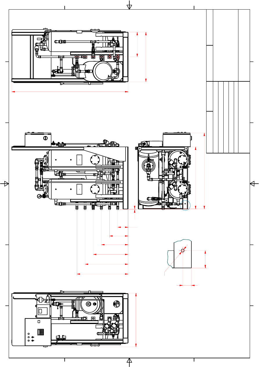
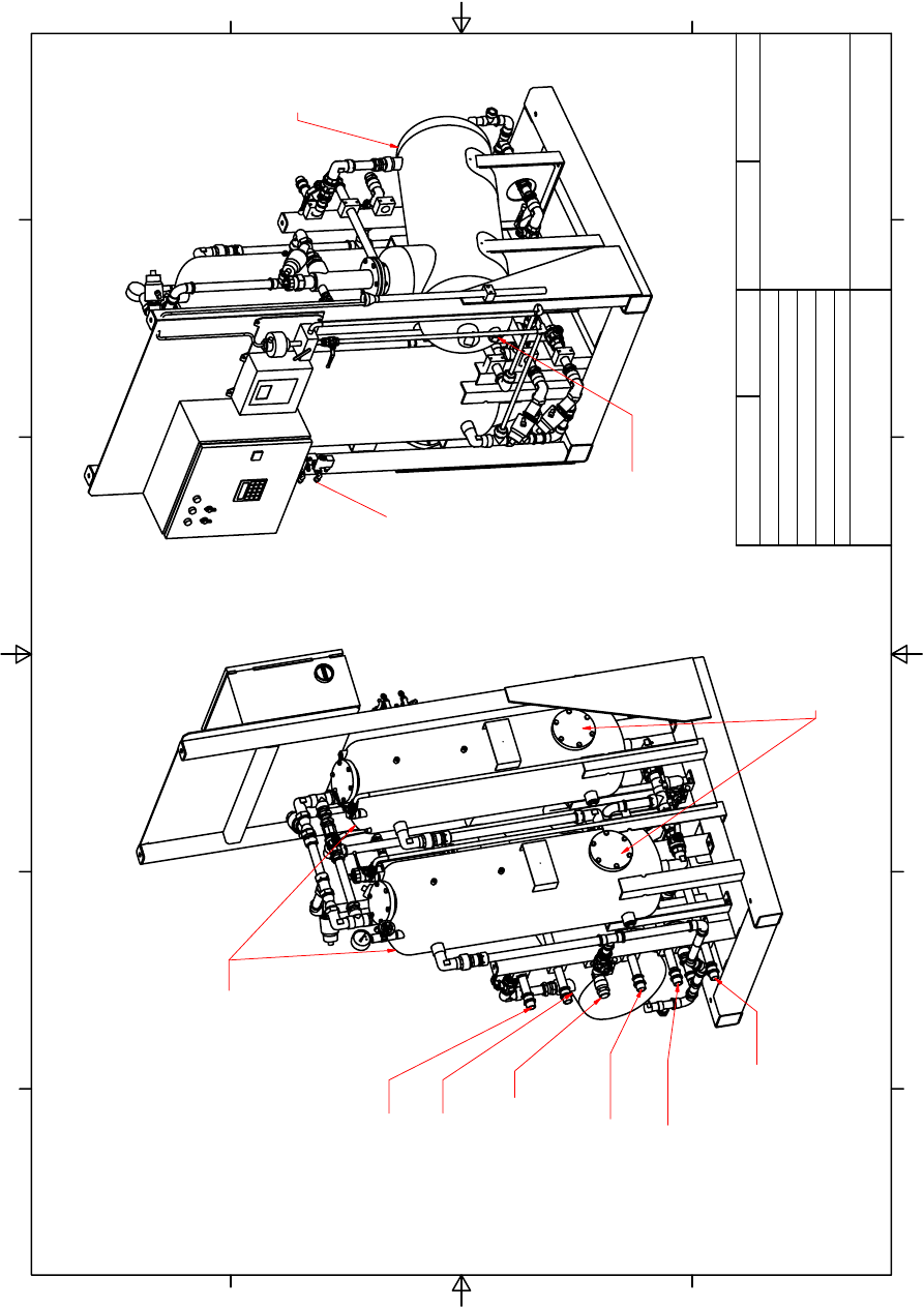
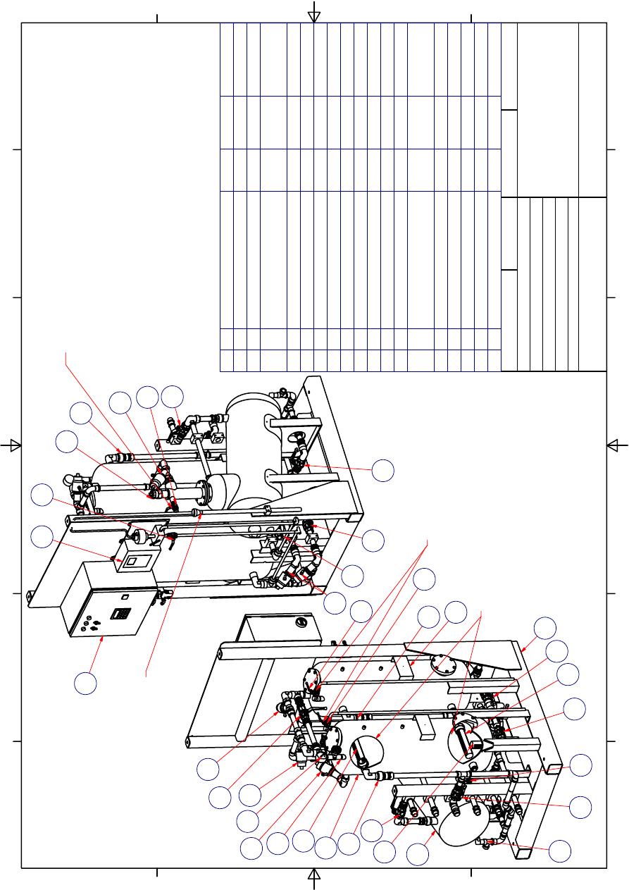
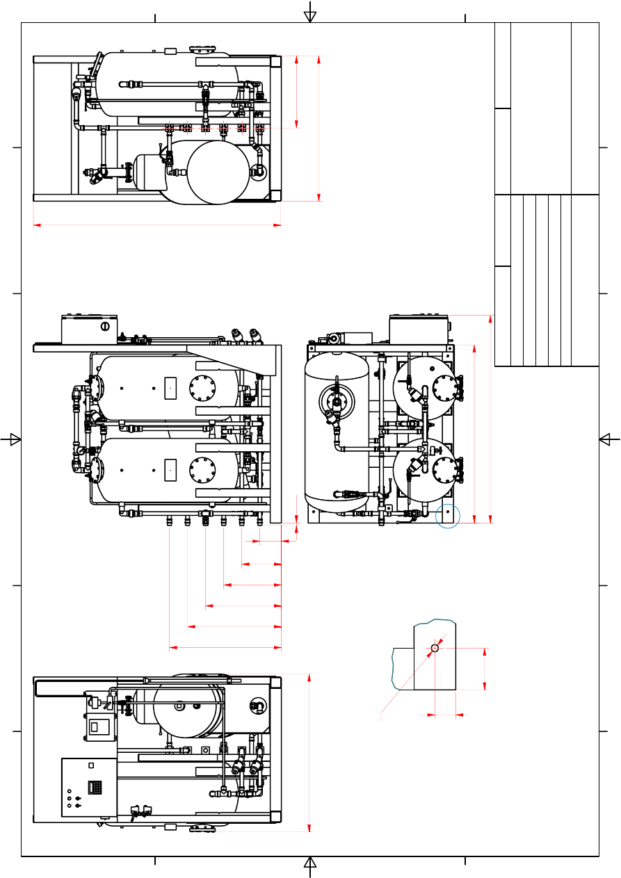
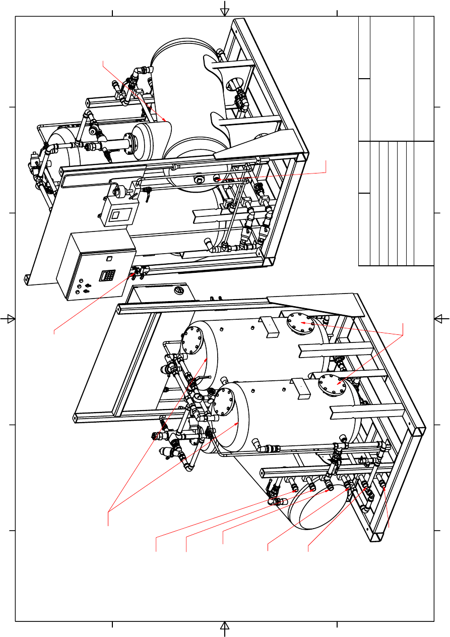
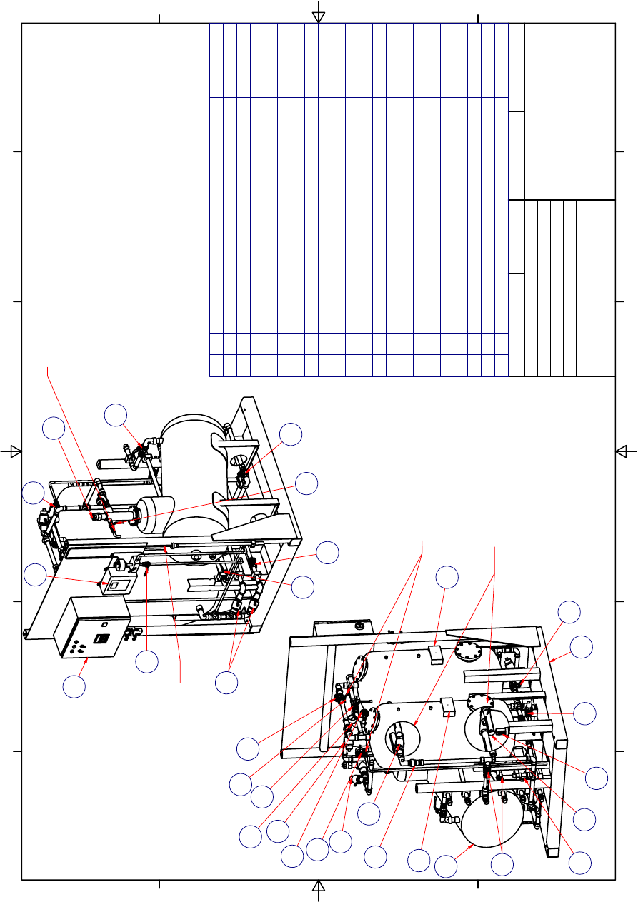
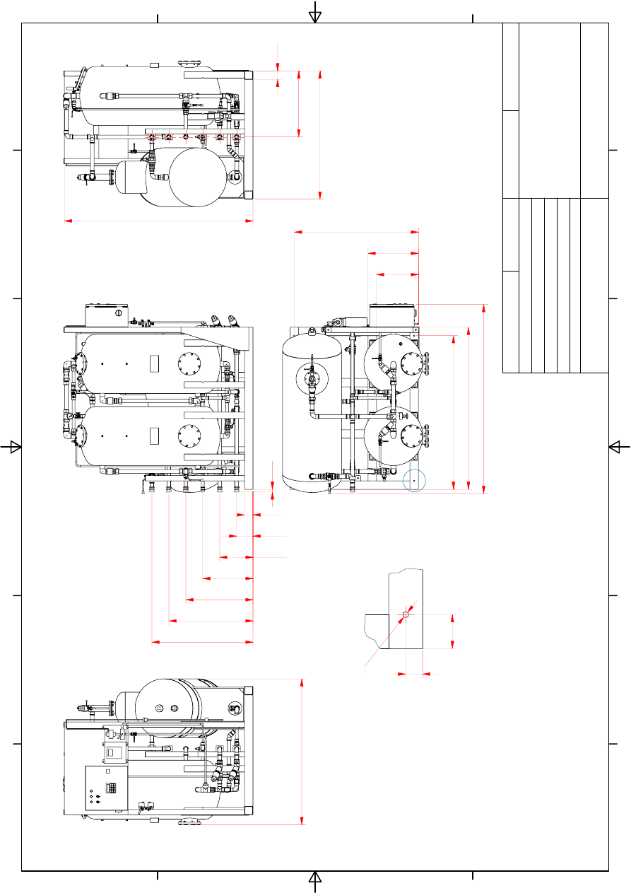
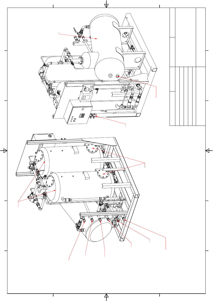
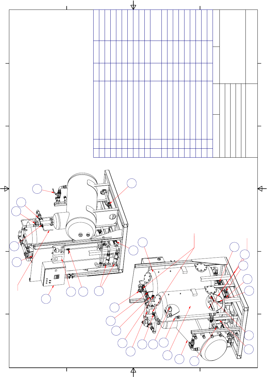
9.0 Mechanical
Drawings
A
1
1
2
2
3
3
4
4
5
5
6
6
A
A
B
B
C
C
D
D
CHECK
RE
V
AP
PR
.
DRAWN
FI
L
E
N
A
M
E
SI
Z
E
ID
N
O
MODE
L
I
D
SCA
LE
JO
WA AB
TU
L
E
B
O
86
5
Götebor
g-SW
E
D
EN
T
e
leph
. +
4
6
31
7
9
5
0
0
40
24-00
1
0-
0
1-
01
3
S
ep
1m3
.ia
m
A3
G
reg Sha
nnon
#6 080
108 ES
24
-001
0-
01
1:
1
5
24-0010
-01
200
4-09
-1
7
GA,
M
A
JO
R
DI
MENSI
O
N
S
JOWA 3SEP
OW
S 1 m
3/
h
M
A
RP
O
L
I
M
O
MEP
C
107(
4
9
)
-0
1
A
16
0
28
5
41
0
53
5
66
0
78
5
95
0
1163
DRY
MA
SS: 26
0 kg
WORKING PRES
SURE
: 2
BAR
MAI
N
T
ENANCE AREA: 500mm
PE
R
IMET
ER
IN
FRONT O
F
UNIT
COMPL
IES
W
IT
H
MARPOL
IMO MEPC 107(49
)
10
377
760
17
84
82
1
40
80
Q
14
(4
x)
1
1
2
2
3
3
4
4
5
5
6
6
A
A
B
B
C
C
D
D
CHECK
RE
V
AP
PR
.
DRAWN
FI
L
E
N
A
M
E
SI
Z
E
ID
N
O
MODE
L
I
D
SCA
LE
JO
WA AB
TU
L
E
B
O
86
5
Götebor
g-SW
E
D
EN
T
e
leph
. +
4
6
31
7
9
5
0
0
40
24-00
1
0-
0
1-
01
3
S
ep
1m3
.ia
m
A3
G
reg Sha
nnon
#6 080
108 ES
24
-001
0-
01
1:
1
0
24-0010
-01
200
4-09
-1
7
IS
O
G
A
, C
O
N
N
E
C
T
IO
N
P
O
IN
T
S
JOWA 3SEP
OW
S 1m
3/
h
M
A
RP
O
L
I
M
O
MEP
C
107(
4
9
)
-0
2
B
: OIL
R
E
LE
ASE
OUTLET,TO
SL
UDGE TANK
M
A
L
E
T
H
RE
AD DN 25
C: OP
TIO
NAL
WATE
R
OU
TL
ET
TO
J
O
W
A
EB
U,
FUR
THER PROCESSED
TO ACHIE
VE <5PPM
MA
LE
TH
REA
D
DN
25
E:
WATE
R
OUT
LE
T,
<15 PPM FO
R
OVERBOARD
D
ICH
AR
GE MA
LE
TH
REA
D D
N
25
FI
L
T
E
R
T
A
NK
S
OI
L
RE
MOV
A
L
TA
NK
F
: BACKF
LUSH WATE
R
,
RECIR
CULA
TED WATER
>15 PPM AND
DRA
IN O
U
TLE
T
T
O
BI
LG
E
TANK
MALE T
H
READ
DN 25
D: WATER INLET
FOR BACKFLUSH
MALE T
H
RE
AD DN25
A
:
OILY WAT
ER INLET
F
R
OM
BILG
E
MALE T
H
READ D
N
25
IN
STRU
MENT
AI
R
COMP
RESS
ION
C
O
U
P
LING DN
8
TA
NK
T
1
AN
OD
E
FI
L
T
E
R
T
A
N
K
ANOD
ES
1
1
2
2
3
3
4
4
5
5
6
6
A
A
B
B
C
C
D
D
CHECK
RE
V
AP
PR
.
DRAWN
FI
L
E
N
A
M
E
SI
Z
E
ID
N
O
MODE
L
I
D
SCA
LE
JO
WA AB
TU
L
E
B
O
86
5
Götebor
g-SW
E
D
EN
T
e
leph
. +
4
6
31
7
9
5
0
0
40
24-00
1
0-
0
1-
01
3
S
ep
1m3
.ia
m
A3
G
reg Sha
nnon
#6 080
108 ES
24
-001
0-
01
1:
1
0
24-0010
-01
200
4-09
-1
7
IS
O
GA
, PART
S
L
IST
JOWA 3SEP
OW
S 1m
3/
h
M
A
RP
O
L
I
M
O
MEP
C
107(
4
9
)
-0
3
0.6 kg
BRASS
Flo
w Re
st
ric
tor D
N
25
1
18
24001
-0
0201
4.8 kg
Control Cabin
et
1
17
87082
-0
0000
7.3 kg
15ppm Oil
Ala
rm
1
16
22303
-2
0224
0.5 kg
BRASS
Sa
fety V
a
lv
e D
u
rgo
GT
77
4
Bar
DN20
1
15
50075
-
2
2002
0.1 kg
Pl
asti
c
F7
5 S
tr
a
iner 0,5m
m L=
21
0mm
2
14
50075
-
2
1002
0.1 kg
Pl
asti
c
F7
5 S
tr
a
iner 1,0m
m L=
21
0mm
2
13
50100
-
2
1002
0.1 kg
Pl
asti
c
3Sep Drain S
trainer 0,5
m
m
2
12
22311
-0
3600
1.1 kg
Oil Sensor
CLM-36N
1
11
10109
-0
0002
0.1 kg
BRASS
Pre
ssure
ga
ug
e, 0-1
0 Bar
1
10
10107
-0
8436
0.1 kg
BRASS
P
R
E
SSURE
GAUGE V
A
LVE
1
9
19001
-1
5156
0.2 kg
Brass
BALL VALVE
DN
15
4
8
19054
-2
5256
0.7 kg
BRASS
BALL VALVE
DN
25
7
7
19059
-2
5256
0.9 kg
BRASS
3-Way
Ball v
a
lve D
N
2
5
1
6
22304
-0
0256
1.5 kg
BRASS
Pn
eumatic s
o
lenoid
v
a
lv
e
DN2
5
Normally Closed
5
5
95030
-0
0006
0.5 kg
bras
s
Non-Return Valv
e DN25
2
4
50075
-5
0101
25
.4 kg
AISI
316
Filter Ta
nk
75
l
2
3
24-001
0
-01
43
.4 kg
AISI
316
GRAVI
T
Y
SEP T
A
NK
75l
1
2
24-001
0
-01
93
.6 kg
S235
3Sep Frame 1,0m
3
/h
1
1
ID NUMBE
R
MASS
MT
RL
DES
CR
IPTIO
N
QT
ITE
7
4
10
9
5
5
5
8
8
3
3
7
7
7
2
1
5
7
7
5
8
11
4
4
6
NO
TES:
1.
I
N
T
E
RNAL
P
IPE SPEC: 28 x
1.
2 MT
R
L
:
COPPER
2.
I
N
TERN
AL
P
L
UMB
ING CONN
ECTI
ONS IN
BR
ASS AN
D
COPPER P
R
E
SS F
ITTI
NG
S
YST
EM WITH OIL RE
S
IST
ANT
S
EALS
3.
ALL T
A
NKS
ANODE
PROTECTE
D
4.
SK
ID F
R
AME
CO
NS
T
R
UCTED I
N
S235
ST
E
E
L
5
. FILT
ER MATERIAL
JOWA
F-200, 50k
g TOTAL (
2
x25kg)
GR
A
V
IT
Y S
E
PARAT
OR TANK
OIL RELEAS
E SA
MPLE P
O
INT
EFFLUENT
SA
M
P
L
E
POINT
FI
LT
ER T
A
NKS
OIL
RELEASE
SAMP
LE
POINT
7
7
13
12
14
CU
T
A
W
AY
VI
E
W
S
15
17
16
8
18
A
1
1
2
2
3
3
4
4
5
5
6
6
A
A
B
B
C
C
D
D
CHECK
RE
V
AP
PR
.
DRAWN
FI
L
E
N
A
M
E
SI
Z
E
ID
N
O
MODE
L
I
D
SCA
LE
JO
WA AB
TU
L
E
B
O
86
5
Götebor
g-SW
E
D
EN
T
e
leph
. +
4
6
31
7
9
5
0
0
40
24
-00
25
-01
-01
3S
ep 2
,5
m
3.
ia
m
A3
G
reg Sha
nnon
#6 080
108 ES
2
4
-00
25-01
1:
1
5
24-0
025-01
200
4-07
-0
6
GA,
M
A
JO
R
DI
MENSI
O
N
S
JOWA 3SEP
OW
S 2,5m
3/h
M
A
RP
O
L
I
M
O
MEP
C
107(
4
9
)
-0
1
A
15
5
28
5
41
5
54
5
67
5
80
5
11
37
517
1045
DRY
MA
SS: 400 kg
WORKING
PRES
SURE: 2 B
A
R
MAI
NT
ENANCE
AREA:
500mm PE
R
IMETER I
N
F
R
ONT
OF UNIT
CO
MPL
IES
W
ITH MARPOL
IMO MEPC 107(49
)
19
128
0
17
80
1493
40
80
Q
14
(4
x)
1
1
2
2
3
3
4
4
5
5
6
6
A
A
B
B
C
C
D
D
CHECK
RE
V
AP
PR
.
DRAWN
FI
L
E
N
A
M
E
SI
Z
E
ID
N
O
MODE
L
I
D
SCA
LE
JO
WA AB
TU
L
E
B
O
86
5
Götebor
g-SW
E
D
EN
T
e
leph
. +
4
6
31
7
9
5
0
0
40
24
-00
25
-01
-01
3S
ep 2
,5
m
3.
ia
m
A3
G
reg Sha
nnon
#6 080
108 ES
2
4
-00
25-01
1:
1
0
24-0
025-01
200
4-07
-0
6
IS
O
G
A
, C
O
N
N
E
C
T
IO
N
P
O
IN
T
S
JOWA 3SEP
OW
S 2,5m
3/h
M
A
RP
O
L
I
M
O
MEP
C
107(
4
9
)
-0
2
FILTE
R T
A
NK
S
OI
L
REM
O
VAL
TANK
F: B
A
CKF
LUSH WAT
ER
,
REC
IRCU
LATED WAT
ER
>15 PPM AND DRAI
N
OUT
LET
TO BI
LGE
T
A
NK
MALE THREAD
DN 25
E
: WA
TE
R
OU
TLE
T
,
<
15 PPM FO
R
OVERBOARD
DI
CH
AR
GE
MALE TH
READ DN 25
D: WA
TER
INLE
T,
FO
R S
Y
S
TE
M
BA
C
K
FLUSH
MA
LE
T
H
REA
D
DN 25
C: OPT
IO
NAL
WATE
R
OUT
LET
TO JOWA EB
U
,
FU
RTHE
R PROCESSED
TO ACH
IEVE <5PP
M
MAL
E T
H
READ
DN 25
B:
OIL RELEAS
E
OU
TLET
,TO
S
L
U
D
GE
T
A
NK
MALE THREAD DN
25
A:
O
IL
Y
WAT
ER INLET
FR
OM BII
LGE
MALE T
H
READ DN
25
INST
RU
MENT
AIR
COMP
R
ESSIO
N
COUPLING DN 8
TA
N
K
T
1
ANOD
E
FI
L
T
ER T
A
NK
A
N
ODES
1
1
2
2
3
3
4
4
5
5
6
6
A
A
B
B
C
C
D
D
CHECK
RE
V
AP
PR
.
DRAWN
FI
L
E
N
A
M
E
SI
Z
E
ID
N
O
MODE
L
I
D
SCA
LE
JO
WA AB
TU
L
E
B
O
86
5
Götebor
g-SW
E
D
EN
T
e
leph
. +
4
6
31
7
9
5
0
0
40
24
-00
25
-01
-01
3S
ep 2
,5
m
3.
ia
m
A3
G
reg Sha
nnon
#6 080
108 ES
2
4
-00
25-01
1:
1
5
24-0
025-01
200
4-07
-0
6
IS
O
GA
, PART
S
L
IST
JOWA 3SEP
OW
S 2,5m
3/h
M
A
RP
O
L
I
M
O
MEP
C
107(
4
9
)
-0
3
0.6 kg
BRASS
Flo
w Re
st
ric
tor D
N
25
1
18
24001
-0
0201
4.8 kg
Control Cabin
et
1
17
87082
-0
0000
7.3 kg
15ppm Oil
Ala
rm
1
16
22303
-2
0224
0.5 kg
BRASS
Sa
fety V
a
lv
e D
u
rgo
GT
77
4
Bar
DN20
1
15
50100
-
2
2002
0.1 kg
Pl
asti
c
3Sep Drain S
trainer 0,5
m
m
2
14
50150
-
2
0001
2.2 kg
Pl
asti
c
F1
50
S
trainer
0,5mm
4
13
50150
-
2
0002
2.2 kg
Pl
asti
c
F1
50
S
trainer
1,0mm.ip
t
4
12
19001
-1
5156
0.2 kg
Brass
BALL VALVE
DN
15
4
11
22311
-0
3600
1.1 kg
Oil Sensor
CLM-36N
1
10
10107
-0
8436
0.1 kg
Brass
P
R
E
SSURE
GAUGE V
A
LVE
DN
8
1
9
10109
-0
0152
0.1 kg
Brass
Pre
ssure
ga
ug
e, 0-1
0 Bar
1
8
22304
-0
0256
1.5 kg
BRASS
Pn
eumatic s
o
lenoid
v
a
lv
e
DN2
5
NC
5
7
19059
-2
5256
0.9 kg
BRASS
3-Way
Ball v
a
lve D
N
2
5
1
6
95030
-0
0006
0.5 kg
bras
s
Non-Return Valv
e DN25
2
5
19054
-2
5256
0.7 kg
BRASS
BALL VALVE
DN
25
7
4
50150
-0
0101
56
.6 kg
AISI
316L
FILTER TANK 150 L
2
3
24-002
5
-01-50
75
.6 kg
AISI
316L
3Sep Gravity
Tank 2,5
m3
h
1
2
24-002
5
-01-30
119.7 k
g
S235
3Sep fra
me 2,5m3
1
1
ID NUMBE
R
MASS
MT
RL
DES
CR
IPTIO
N
QT
ITE
1
2
3
3
5
4
4
4
4
4
4
6
7
7
8
7
9
10
11
3
11
NO
TES:
1. I
N
T
E
RNAL
PIP
E
SPEC:
28 x
1.
2 MT
RL:
COPPER
2. I
N
TERNAL
PLU
MBING CONN
ECTION
S
IN BRASS A
N
D
COPPER
PRE
SS
FI
T
T
ING
SY
ST
EM
WI
T
H
OIL RE
SIS
T
ANT
SE
ALS
3. AL
L
TAN
K
S AN
OD
E PR
OT
ECTED
4. SKID FRAME
CO
NS
TR
UC
TE
D IN S235 STE
EL
5. FILTER MAT
ERIAL
JOW
A
F
-200,
1
00kg TOTAL (4x
25
kg
SACKS)
EF
FL
UENT SAM
PLE
PO
INT
G
R
AV
ITY SEP
ARAT
O
R
TA
NK
O
IL RELE
ASE SAMPLE PO
IN
T
F
ILTER TANKS
OIL R
E
LE
ASE
SAM
P
LE PO
IN
T
CU
T AWA
Y
VI
EWS
11
7
12
13
14
15
11
16
17
18
A
1
1
2
2
3
3
4
4
5
5
6
6
A
A
B
B
C
C
D
D
CHECK
RE
V
AP
PR
.
DRAWN
FI
L
E
N
A
M
E
SI
Z
E
ID
N
O
MODE
L
I
D
SCA
LE
JO
WA AB
TU
L
E
B
O
86
5
Götebor
g-SW
E
D
EN
T
e
leph
. +
4
6
31
7
9
5
0
0
40
24-00
5
0-
0
1-
01
3
S
ep
5m3
.ia
m
A3
G
reg Sha
nnon
#6 080
108 ES
24
-005
0-
01
1:
2
0
24-0050
-01
200
4-06
-3
0
GA,
M
A
JO
R
DI
MENSI
O
N
S
JOWA 3SEP
OW
S 5 m
3/
h
M
A
RP
O
L
I
M
O
MEP
C
107(
4
9
)
-0
1
A
80
15
4
31
4
47
4
63
4
79
4
95
4
80
62
3
12
10
17
80
DR
Y M
A
SS:
5
1
2
k
g
WORKI
NG PRESSURE: 2
BAR
MA
INTE
N
A
N
C
E
AREA: 5
00mm
PERIME
TER
IN F
RONT
O
F
UNIT
COMPLIES
WIT
H MARPOL
IMO
MEP
C 107(49)
137
6
17
82
25
15
30
1
450
39
5
47
5
11
70
80
40
Q
14(4x)
1
1
2
2
3
3
4
4
5
5
6
6
A
A
B
B
C
C
D
D
CHECK
RE
V
AP
PR
.
DRAWN
FI
L
E
N
A
M
E
SI
Z
E
ID
N
O
MODE
L
I
D
SCA
LE
JO
WA AB
TU
L
E
B
O
86
5
Götebor
g-SW
E
D
EN
T
e
leph
. +
4
6
31
7
9
5
0
0
40
24-00
5
0-
0
1-
01
3
S
ep
5m3
.ia
m
A3
G
reg Sha
nnon
#6 080
108 ES
24
-005
0-
01
1:
1
5
24-0050
-01
200
4-06
-3
0
IS
O
G
A
, C
O
N
N
E
C
T
IO
N
P
O
IN
T
S
JOWA 3SEP
OW
S 5 m
3/
h
M
A
RP
O
L
I
M
O
MEP
C
107(
4
9
)
-0
2
E:
WATER
OUT
LE
T,
<15 PPM F
O
R
OV
ERBO
A
R
D DICHARGE
MALE T
H
READ DN
40
O
IL REMOV
AL
TA
N
K
FI
LTE
R T
A
N
K
S
F: BAC
KF
L
U
S
H
W
A
TER,
R
E
C
IRCU
LA
TED WAT
ER
>15 PPM AND
D
R
AIN OUT
LE
T
T
O
BI
LGE
T
A
NK
MALE THREAD DN 40
B
:
OIL R
E
LE
ASE O
U
T
L
ET
,
T
O
SLU
DGE
TANK
M
A
L
E
T
H
RE
AD DN 40
D:
W
A
TE
R
INL
E
T
, F
O
R
S
Y
S
T
E
M
BACKF
LU
S
H
MALE THREAD D
N
25
A:
O
IL
Y
WAT
ER INLET
FR
OM BII
LGE
MALE T
H
READ DN
40
C
: O
P
TI
ONAL
WAT
ER
OUT
LET
TO JO
WA EBU,
FURTHERPROCE
SSED
TO ACHIE
VE
<5PP
M
MALE THREAD DN 40
TA
N
K
T
1
AN
ODE
S
FI
LT
ER T
A
NK
ANODES
IN
STRU
MENT
AIR
C
O
MPR
ESSI
ON
C
O
U
P
L
ING DN
8
1
1
2
2
3
3
4
4
5
5
6
6
A
A
B
B
C
C
D
D
CHECK
RE
V
AP
PR
.
DRAWN
FI
L
E
N
A
M
E
SI
Z
E
ID
N
O
MODE
L
I
D
SCA
LE
JO
WA AB
TU
L
E
B
O
86
5
Götebor
g-SW
E
D
EN
T
e
leph
. +
4
6
31
7
9
5
0
0
40
24-00
5
0-
0
1-
01
3
S
ep
5m3
.ia
m
A3
G
reg Sha
nnon
#6 080
108 ES
24
-005
0-
01
1:
2
0
24-0050
-01
200
4-06
-3
0
IS
O
GA
, PART
S
L
IST
JOWA 3SEP
OW
S 5m
3/
h
M
A
RP
O
L
I
M
O
MEP
C
107(
4
9
)
-0
3
0.8 kg
BRASS
Flo
w Re
st
ric
tor D
N
32
1
19
24001
-0
0201
4.8 kg
Control Cabin
et
1
18
87082
-0
0000
7.3 kg
15ppm Oil
Ala
rm
1
17
22303
-2
5324
2.1 kg
Brass
Sa
fety V
a
lv
e 4
ba
r
415
5 D
N
25
1
16
50100
-
2
3002
0.1 kg
Pl
asti
c
3Sep Drain S
trainer 0,5
m
m
2
15
50300
-
2
0001
2.2 kg
Pl
asti
c
F3
00
S
trainer
0,5mm
4
14
50300
-
2
0002
2.2 kg
Pl
asti
c
F3
00
S
trainer
1,0mm.ip
t
4
13
19059
-2
5256
0.9 kg
BRASS
3-Way
Ball v
a
lve D
N
2
5
1
12
19054
-2
5256
0.7 kg
BRASS
BALL VALVE
DN
25
5
11
10109
-0
0152
0.1 kg
Brass
Pre
ssure
ga
ug
e, 0-1
0 Bar
1
10
10107
-0
8436
0.1 kg
BRASS
P
R
E
SSURE
GAUGE V
A
LVE
DN
8
1
9
22311
-0
3600
1.1 kg
Oil Sensor
CLM-36N
1
8
19001
-1
5156
0.2 kg
Brass
BALL VALVE
DN
15
4
7
95030
-3
2006
1.2 kg
BRASS
NON
RETU
RN VALVE D
N
32
2
6
22304
-0
0326
2.8 kg
BRASS
P
N
E
U
M
A
TI
C VALVE
N.C
. DN32
5
5
19001
-3
2326
0.8 kg
BRASS
BALL VALVE
DN
32
2
4
50300
-0
0101
80
.8 kg
AISI
316L
FILTER TANK 300 L
2
3
24005
-0
0150
126.6 k
g
AISI
316L
3Sep Gravity
Tank
1
2
24005
-0
0130
130.3 k
g
S235
3Sep fra
me 5m3
1
1
ID NUMBE
R
MASS
MT
RL
DES
CR
IPTIO
N
QT
ITE
NO
TES:
1.
INTERN
AL
PIPE SPEC: 40 x
1.2 MTRL:
C
O
PPER
2.
INT
ERN
A
L
PLUMBI
N
G
CONN
E
C
T
IONS I
N
BRAS
S
AND
COPP
ER PRESS
FI
TTING SYS
TE
M
WITH
OI
L
RESIS
TA
N
T
SE
ALS
3.
ALL TA
NKS A
N
ODE PR
OT
EC
TED
4.
SKID
FRAME CON
STRUCT
ED IN S235 ST
EEL
5. FILT
ER
M
A
TER
IAL
JOW
A
F-2
00, 20
0
kg TOTAL (8
x2
5k
g
)
4
11
5
5
2
8
5
5
12
10
9
11
11
11
4
11
6
7
7
2
1
3
3
13
15
14
FILTE
R
TA
N
K
S
OIL RELEASE
SA
MPLE P
O
INT
CU
T A
W
AY
VIE
WS
GR
A
V
ITY SE
PARATOR
T
A
NK OIL REL
E
ASE
SAMPLE POINT
18
17
7
19
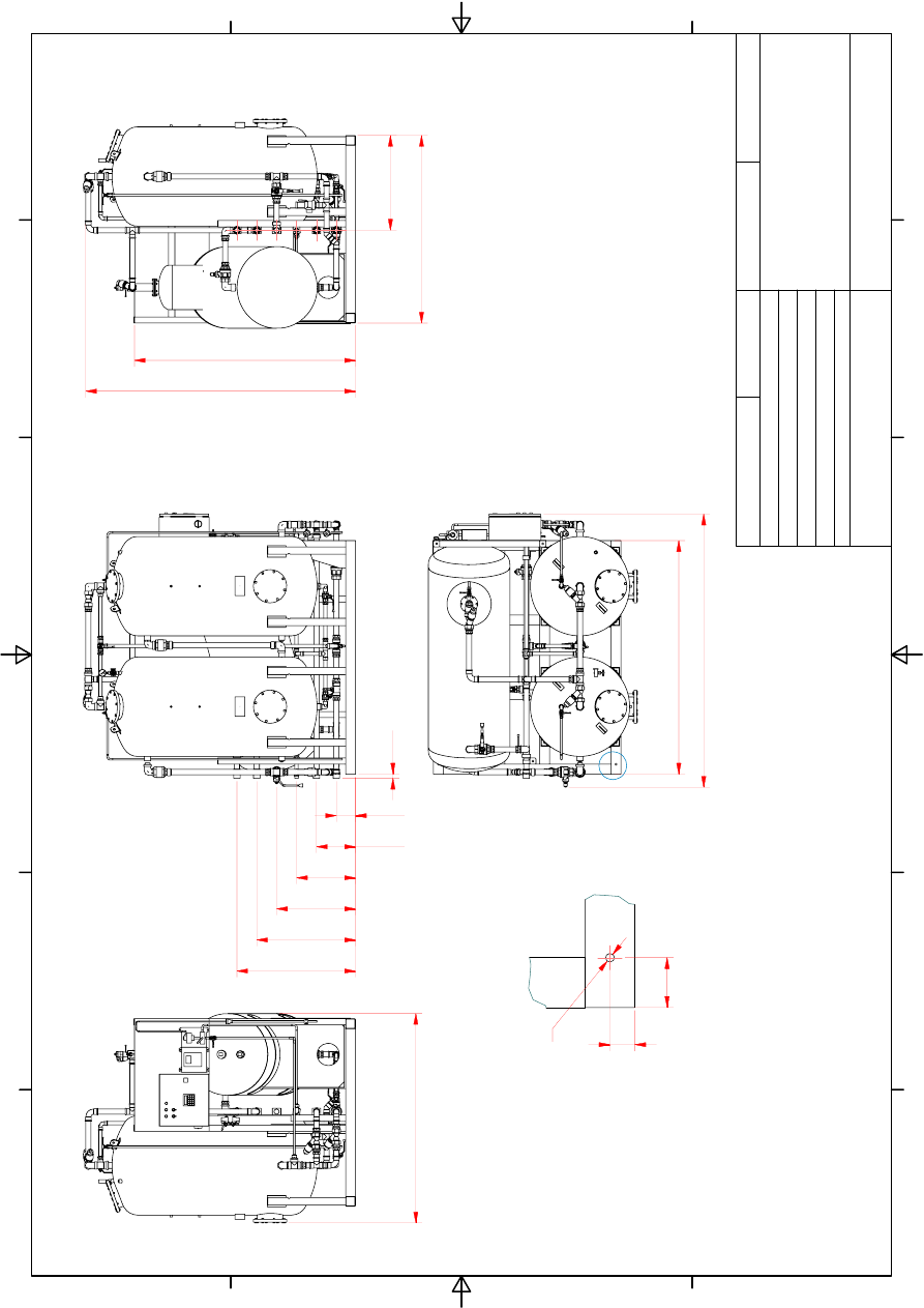
A
1
1
2
2
3
3
4
4
5
5
6
6
A
A
B
B
C
C
D
D
CHECK
RE
V
AP
PR
.
DRAWN
FI
L
E
N
A
M
E
SI
Z
E
ID
N
O
MODE
L
I
D
SCA
LE
JO
WA AB
TU
L
E
B
O
86
5
Götebor
g-SW
E
D
EN
T
e
leph
. +
4
6
31
7
9
5
0
0
40
24
-0
10
0
-0
1-
01
3
S
ep
10
m3.
ia
m
A3
G
reg Sha
nnon
#3 080
108 ES
24
-010
0-
01
1:
2
5
24-0100
-01
200
4-07
-1
2
GA,
M
A
JO
R
DI
MENSI
O
N
S
JOWA 3SEP
OW
S 10m
3/
h
M
A
RP
O
L
I
M
O
MEP
C
107(
4
9
)
-0
1
A
16
85
763
1510
21
98
17
80
21
73
15
4
31
4
47
5
63
5
79
5
95
5
DRY
MASS: 850 kg
WORKI
NG PRESSURE:
2
B
A
R
MA
IN
TE
N
A
N
C
E
AREA:
500mm
PERIM
ETER
IN F
RONT
O
F
UN
IT
COMPLIES
WITH
MARPOL
IMO MEPC 1
07(49)
33
18
8
0
40
80
Q
14
(4
x)
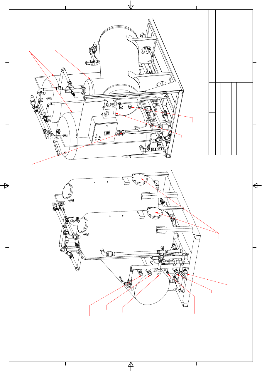
1
1
2
2
3
3
4
4
5
5
6
6
A
A
B
B
C
C
D
D
CHECK
RE
V
AP
PR
.
DRAWN
FI
L
E
N
A
M
E
SI
Z
E
ID
N
O
MODE
L
I
D
SCA
LE
JO
WA AB
TU
L
E
B
O
86
5
Götebor
g-SW
E
D
EN
T
e
leph
. +
4
6
31
7
9
5
0
0
40
24
-0
10
0
-0
1-
01
3
S
ep
10
m3.
ia
m
A3
G
reg Sha
nnon
#3 080
108 ES
24
-010
0-
01
1:
1
5
24-0100
-01
200
4-07
-1
2
IS
O
G
A
, C
O
N
N
E
C
T
IO
N
P
O
IN
T
S
JOWA 3SEP
OW
S 10m
3/
h
M
A
RP
O
L
I
M
O
MEP
C
107(
4
9
)
-0
2
F
: BACK
FLUSH WA
TER,
REC
IRCU
LATE
D
WA
TER
>15 PP
M
AND DRAI
N OU
T
L
ET
T
O
BILG
E T
A
N
K
M
A
LE T
H
R
EAD
DN
40
E:
W
A
T
E
R OUTLET, <
1
5
PPM
F
O
R
O
VERBOARD DI
C
H
A
R
GE
MALE THREAD DN 40
D: WA
TER
INLET,
F
OR
SY
S
T
EM BACKFL
USH
MA
LE
TH
REA
D
DN
25
C
: O
P
T
ION
AL
WATER
OUT
LET
TO
JO
WA
EBU,
FURTHE
RPROCESSED
TO A
C
HI
EVE
<5
P
PM
MALE
TH
REA
D
D
N
4
0
B: O
IL RE
L
E
ASE OU
TLE
T
,
TO
S
L
UDG
E TAN
K
MALE T
H
READ D
N
40
A:
OILY WAT
ER INLET
FR
OM
BILG
E
MALE
TH
REA
D
D
N
40
FI
LT
ER T
A
N
K
S
O
IL REMOVAL
TANK
INSTRUM
E
NT
AI
R
COMP
RESS
ION
COUPL
ING DN
8
TA
N
K
T
1
ANO
DE
FIL
TER T
A
NKS
OIL CON
T
ENT
ALARM 15P
P
M
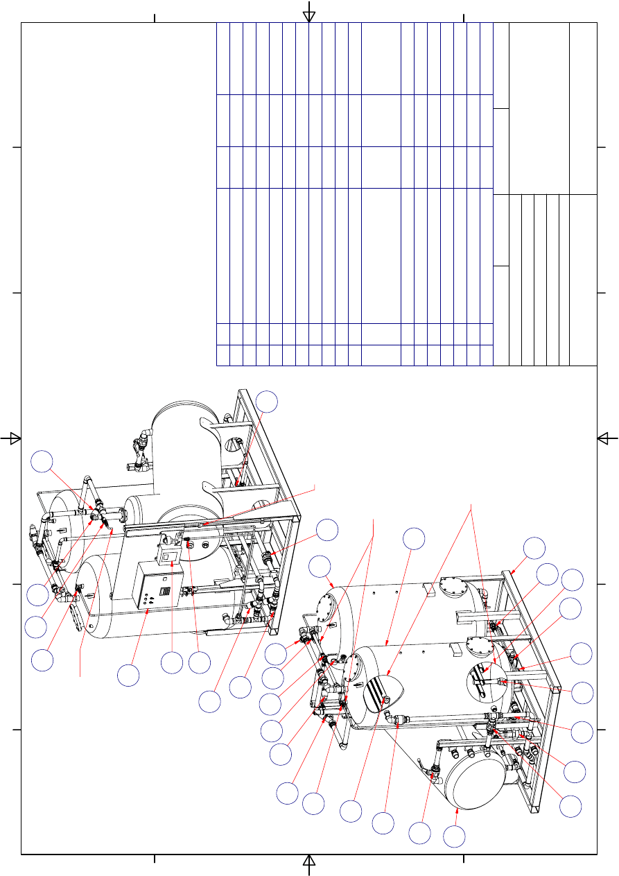
1
1
2
2
3
3
4
4
5
5
6
6
A
A
B
B
C
C
D
D
CHECK
RE
V
AP
PR
.
DRAWN
FI
L
E
N
A
M
E
SI
Z
E
ID
N
O
MODE
L
I
D
SCA
LE
JO
WA AB
TU
L
E
B
O
86
5
Götebor
g-SW
E
D
EN
T
e
leph
. +
4
6
31
7
9
5
0
0
40
24
-0
10
0
-0
1-
01
3
S
ep
10
m3.
ia
m
A3
G
reg Sha
nnon
#3 080
108 ES
24
-010
0-
01
1:
2
0
24-0100
-01
200
4-07
-1
2
IS
O
GA
, PART
S
L
IST
JOWA 3SEP
OW
S 10m
3/
h
M
A
RP
O
L
I
M
O
MEP
C
107(
4
9
)
-0
3
3 k
g
Brass
Flo
w Re
st
ric
tor D
N
40
1
18
50100
-2
4012
2.4 kg
Pl
asti
c
3Sep Drain S
trainer 0,5
m
m
4
17
50750
-2
0001
4.2 kg
Pl
asti
c
F7
50
S
trainer
0,5mm
6
16
50750
-2
0002
4.2 kg
Pl
asti
c
F7
50
S
trainer
1,0mm
6
15
24001
-0
0201
4.8 kg
Control Cabin
et
1
14
87082
-0
0000
7.3 kg
15ppm Oil
Ala
rm
1
13
22303
-3
2404
2.6 kg
Brass
Sa
fety V
a
lv
e 4
ba
r
415
5 D
N
32
1
12
19001
-1
5156
0.2 kg
Brass
BALL
VALVE
DN
15
Bras
s
4
11
10109
-0
0002
0.1 kg
Brass
Pre
ssure
ga
ug
e, 0-1
0 Bar
1
10
22311
-0
3600
1.1 kg
Oil Sensor
CLM-36N
1
9
19059
-2
5256
0.9 kg
BRASS
3-Way
Ball v
a
lve D
N
2
5
1
8
22304
-0
0406
3.2 kg
BRASS
P
N
E
U
M
A
TI
C SO
LENOI
D
V
A
LVE OBLIQUE SE
T
T
ING
DN40 NC
5
7
19001
-4
0406
3.5 kg
Brass
BALL VALVE
DN
40
2
6
95030
-4
2006
2.9 kg
BRASS
NON
RETU
RN VALVE D
N
40
2
5
19054
-2
5256
0.7 kg
BRASS
BALL VALVE
DN
25
5
4
50750
-0
0101
176.2 k
g
AISI
316L
FILTER TANK 750L
2
3
24-010
0
-01-50
204.1 k
g
AISI
316L
3Sep Gravity
Tank 10
m3h
1
2
24-010
0
-01-30
149.2 k
g
S235
3Sep fra
me 10m3
1
1
ID NUMBE
R
MASS
MT
RL
DES
CR
IPTIO
N
QT
ITE
6
4
4
4
4
6
5
7
11
11
7
7
10
3
3
1
2
11
7
7
4
9
NO
TES:
1
.
IN
T
E
RN
A
L
PIP
E
SPE
C:
4
2
x
1.6 MT
RL: COPPER
2
.
IN
T
E
RN
A
L
PLUMBING CONN
E
C
T
IONS
IN
BRASS
AND
CO
P
PER PRE
SS
F
ITTI
N
G
S
YST
E
M
WIT
H OIL RESI
ST
A
N
T
SEALS
3
. A
L
L TA
N
K
S
ANODE
PROT
ECTED
4
. S
K
ID F
R
AM
E
CO
NST
RUCTED IN
S235
STEE
L
5
.
F
IL
T
E
R
MAT
ERIA
L
J
O
W
A
F
-2
00,
50
0kg
T
O
T
A
L (
2
0x25k
g)
GRAVI
T
Y
S
EPA
RATOR
TANK OIL RE
LE
ASE
SA
MPLE P
O
IN
T
FI
LT
ER T
A
NKS
OI
L RELEASE
SAMP
LE
POINT
CU
T A
W
AY
VIE
WS
7
8
11
13
EFFLUENT
SAMPLE
POINT
12
14
11
15
16
17
18
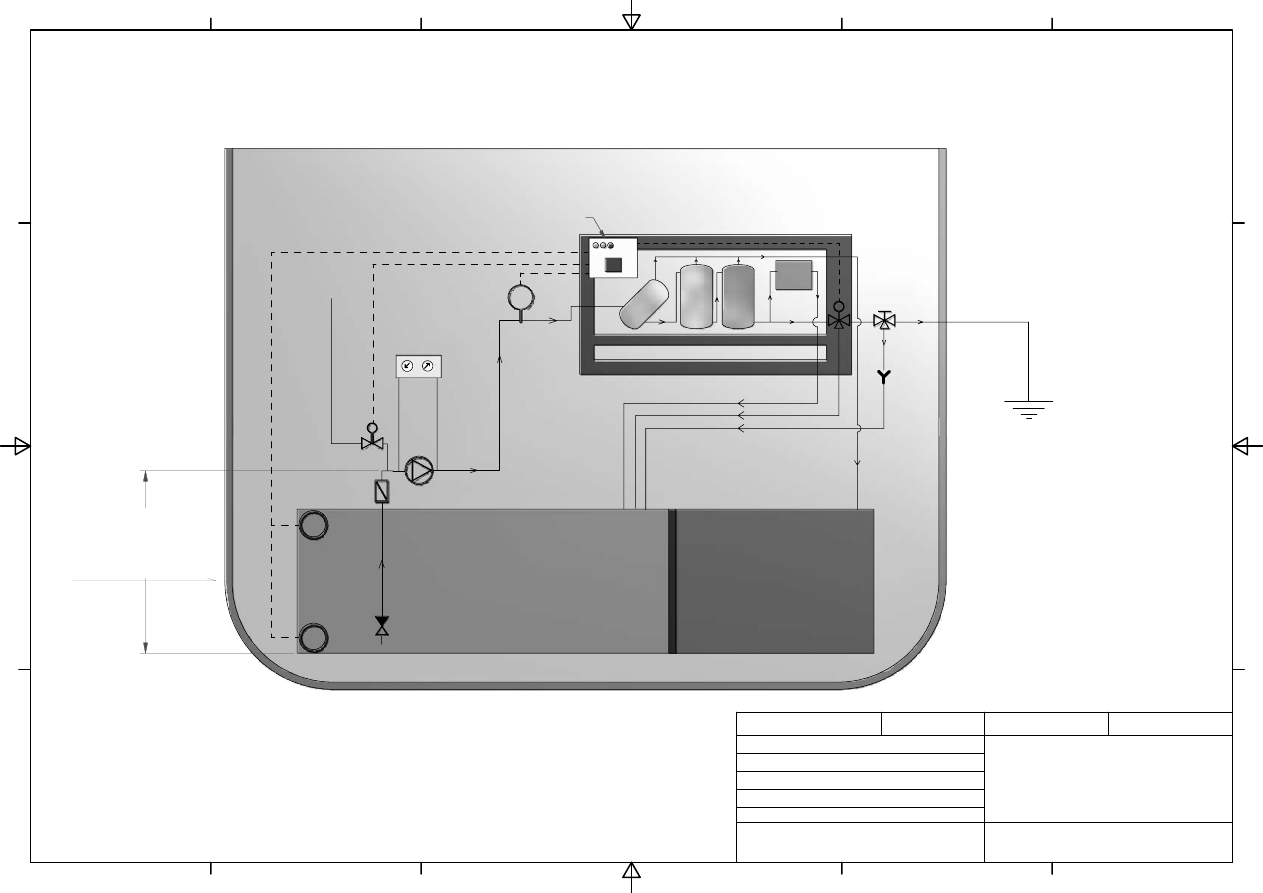
1
1
2
2
3
3
4
4
5
5
6
6
A
A
B
B
C
C
D
D
CHECK
REV
APPR.
DRAWN
FILE NAME
SIZE
ID NO
MODEL ID
SCALE
JOWA AB
TULEBO 865
Göteborg-SWEDEN
Teleph. +46 31 726 54 00
24-000-06-01 3Sep Rec install.ipt
A3
A Sandgren
24-0000-06-01
Not to scale
24-0000-06-01
2006-05-23
Recommended installation
JOWA 3Sep
www.jowa.se
JOWA 3Sep OWS - MEPC 107(49)
Recommended Installation for optimal performance
15ppm
Alarm
3Sep skid
Overboard
Bilge Tank
1. Bilge pump - JOWA supply
2. Prime water solenoid valve - JOWA supply (optional)
3. Pressure gauge station - JOWA supply
4. Dry running protection flow switch - JOWA supply (optional)
5. Low level stop - Yard supply (optional)
6. High level start - Yard supply (optional)
7. Manual valve - Yard supply
8. Auto return to bilge
9. Strainer - Yard supply
10. Non-return valve - Yard supply
OBS!
Height less than
4,5 m
Control cabinet
Prime water
LS
LS
1.
2.
3.
4.
5.
6.
Sludge Tank
7.
FS
8.
10.
9.
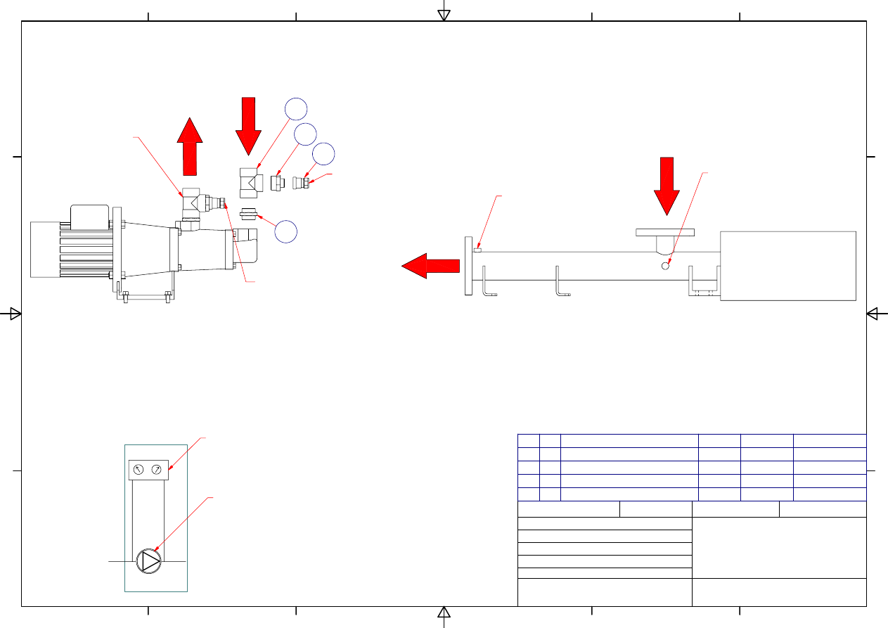
1
1
2
2
3
3
4
4
5
5
6
6
A
A
B
B
C
C
D
D
CHECK
REV
APPR.
DRAWN
FILE NAME
SIZE
ID NO
MODEL ID
SCALE
JOWA AB
TULEBO 865
Göteborg-SWEDEN
Teleph. +46 31 726 54 00
24-000-06-01 3Sep Rec install.ipt
A3
A Sandgren
24-0000-06-01
NOT TO SCALE
2006-05-23
RECOMMENDED INSTALLATION
3SEP Pump PressGauge Board
JOWA 3SEP PUMPS ALL SIZES
24-0000-06-02
Yard Supply
0,107 kg
Brass
D-nipple 25-8 brass
2
4
Yard Supply
0,060 kg
BRASS
Squeeze Connector Brass DN8
2
3
Yard Supply
0,203 kg
BRASS
T CONNECTION DN 25
2
2
Yard Supply
0,083 kg
BRASS
D-NIPPLE DN25
2
1
ID NUMBER
MASS
MTRL
DESCRIPTION
QT
ITE
NOTE: TAKE OFF POINTS FOR PRESSURE
GAUGE BOARD SHOULD BE INSTALLED AS
CLOSE AS POSSIBLE TO THE PUMP SUCTION
(-VE) AND PRESSURE (+VE) INLET/OUTLET
PRESSURE
GAUGE BOARD
PUMP
PUMP FOR 3SEP 1.0 AND 2.5 m3/h
JOWA SUPPLY - LOOSE
PUMP FOR 3SEP 5.0 AND 10.0m3/h
JOWA SUPPLY - LOOSE
FROM
BILGE
TO
3SEP
TO
3SEP
FROM
BILGE
TAKE OFF POINT
FOR PRESS GAUGE
BOARD +VE SIDE
DN8 COMPRESSION
COUPLING YARD SUPPLY
TAKE OFF POINT
FOR PRESS GAUGE
BOARD -VE SIDE
DN8 COMPRESSION
COUPLING YARD SUPPLY
TAKE OFF POINT
FOR PRESS GAUGE
BOARD +VE SIDE
DN8 COMPRESSION
COUPLING YARD SUPPLY
TAKE OFF POINT
FOR PRESS GAUGE
BOARD -VE SIDE
DN8 COMPRESSION
COUPLING
YARD SUPPLY
ASSEMBLED
YARD SUPPLY
COMPONENTS
2
4
3
1
EXPLODED VIEW
YARD SUPPLY
COMPONENTS
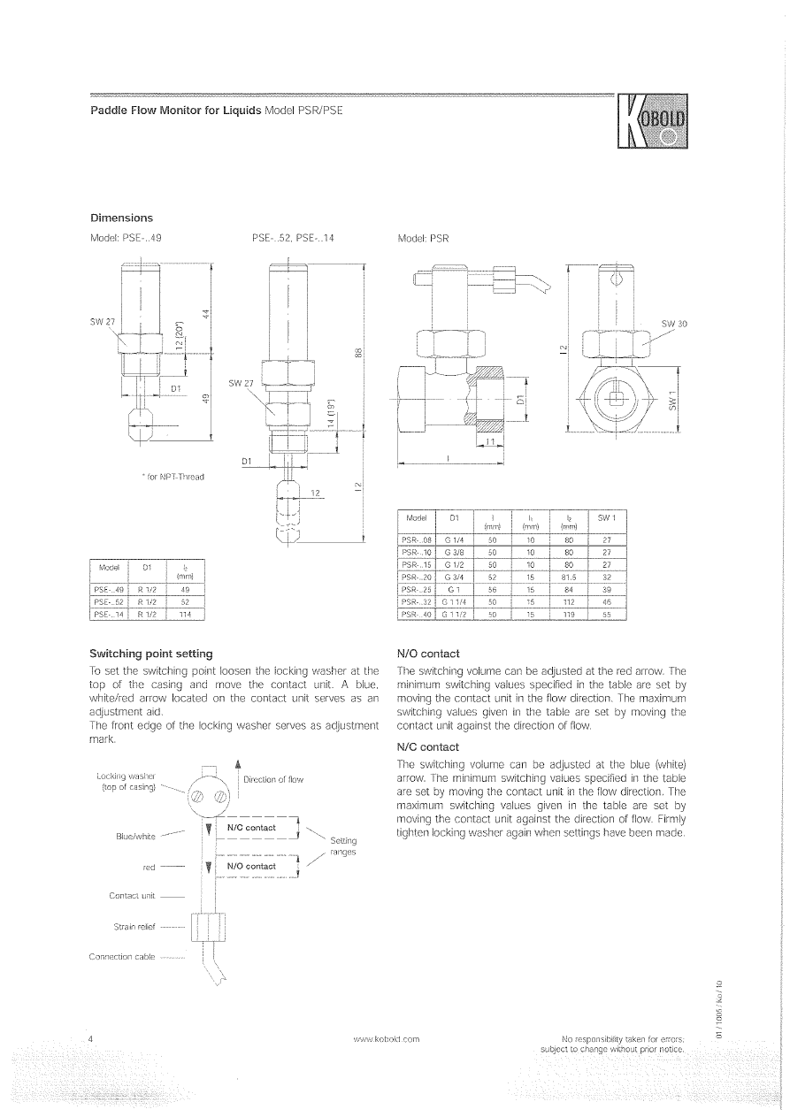
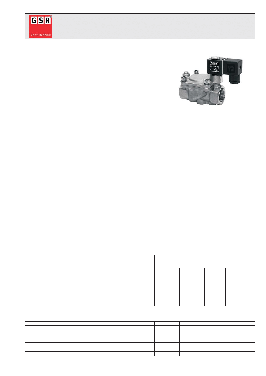
Standardtype
Ventil in Ruhestellung geschlossen - (NC). Bei erregtem Magnet baut
sich die Druckdifferenz von der Sekundärseite der Membrane über
die Servobohrung ab. Die wirksame Druckdifferenz hebt die
Membrane vom Ventilsitz ab. Der angegebene Mindestdruck muß
als Druckdifferenz für eine einwandfreie Funktion der Servosteuerung
immer vorhanden sein.
Valve normally closed - NC.
When energised, the pressure decomposes on the secondary side
of the diaphragm via the pilot hole. The pressure differential lifts the
piston from the seat. The stated minimum pressure is always
necessary as pressure differential for accurate operation.
Standard type
Stand/State: 05/2007
GSR-MK-JM/DB/40
Irrtum und Änderungen vorbehalten - Errors excepted, subject to change!
Baureihe 40 - Type 40
2/2 - Wege Magnetventil
2/2 - Way Solenoid valve
Steuerungsart:
servogesteuert
Metall. Innenteile:
Messing und Edelstahl 1.4104
Type of control:
pilot operated
Metallic internals:
Brass and stainless steel (AISI 430F)
Konstruktion:
Sitzventil mit Membrandichtung
Dichtung:
NBR
Construction:
Diaphragm design
Sealing:
NBR
Anschluß:
G1/4-G2, DIN ISO 228
Einbaulage:
beliebig, Magnet vorzugsweise stehend
Connection:
G1/4-G2, DIN ISO 228
Installation:
actuator in any position, preferable upright
Druck:
0,3-20 bar (s. Tabelle)
Anschlußspannung:
AC: 24,42,110,230V 50Hz
Pressure:
0,3-20 bar (see table)
Supply voltage:
DC: 24,110,196V=
Durchflußmedium:
neutrale, gasförmige u. flüssige Medien
Spannungstoleranz:
+5% / -10%
Medium:
neutral, gaseous and liquid medium
Voltage tolerance:
+5% / -10%
Viskosität:
22mm²/s
Leistungsaufnahme:
1182 = 6,8 Watt 0182 = 14,5/10,5 VA
Viscosity:
22mm²/s
Power-consumption:
1032 = 11
Watt 0032 = 24/15 VA
1012 = 18,5 Watt 0012 = 35/24 VA
1148 = 10
Watt 0148 = 9 VA
Mediumtemperatur:
-10 bis +80°C
Schutzart:
IP65 nach DIN 40050
Medium temperature:
-10 up to +80°C
Protection class:
IP65 according to DIN 40050
Umgebungstemperatur: +35°C
Einschaltdauer:
100% ED-VDE 0580
Ambient temperature:
+35°C
Duty factor:
100% ED-VDE 0580
Ventilgehäuse:
../10../.. = Messing / Brass
Kabelanschluß:
Gerätestecker DIN 43650
Body material:
../08../.. = Edelst.1.4581 / St. steel (AISI 316Ti)
Cable connection:
DIN 43650 - plug
max. Druck bei Magnettype / max. pressure reg. solen. type
DN
Sitz
Kv-Wert
Standardtype
Ex-Schutz
Orifice
Flow-rate
Standard type
Ex II 2G Eex m II T4
G
1/4
13,5
1,6
D4021/1001/....
0,3-20
0,3-20
0,3-20
0,3-20
3/8
13,5
3,3
D4022/1001/....
0,3-20
0,3-20
0,3-20
0,3-20
1/2
13,5
3,8
D4023/1001/....
0,3-20
0,3-20
0,3-20
0,3-20
3/4
27,5
11,0
D4024/1001/....
0,3-16
0,3-20
0,3-20
0,3-20
1
27,5
13,0
D4025/1001/....
0,3-16
0,3-20
0,3-20
0,3-20
5/4
40
30,0
B4026/1001/....
-
0,5-16
0,5-16
0,5-16
6/4
40
32,0
B4027/1001/....
-
0,5-16
0,5-16
0,5-16
2
50
36,0
B4028/1001/....
-
0,5-16
0,5-16
0,5-16
Edelstahl 1.4581/ Stainless steel 1.4581 (AISI 316 Ti)
1/4
13
1,6
D4021/0801/....
-
0,3-20
0,3-20
0,3-20
3/8
13
3,3
D4022/0801/....
-
0,3-20
0,3-20
0,3-20
1/2
13
3,8
D4023/0801/....
-
0,3-20
0,3-20
0,3-20
3/4
25
11,0
D4024/0801/....
-
0,3-20
0,3-20
0,3-20
1
25
13,0
D4025/0801/....
-
0,3-20
0,3-20
0,3-20
5/4
40
30,0
B4026/0801/....
-
0,5-16
0,5-16
0,5-16
6/4
40
32,0
B4027/0801/....
-
0,5-16
0,5-16
0,5-16
2
50
36,0
B4028/0801/....
-
0,5-16
0,5-16
0,5-16
Ømm
m³/h
.182
.032
.012-NO
.148
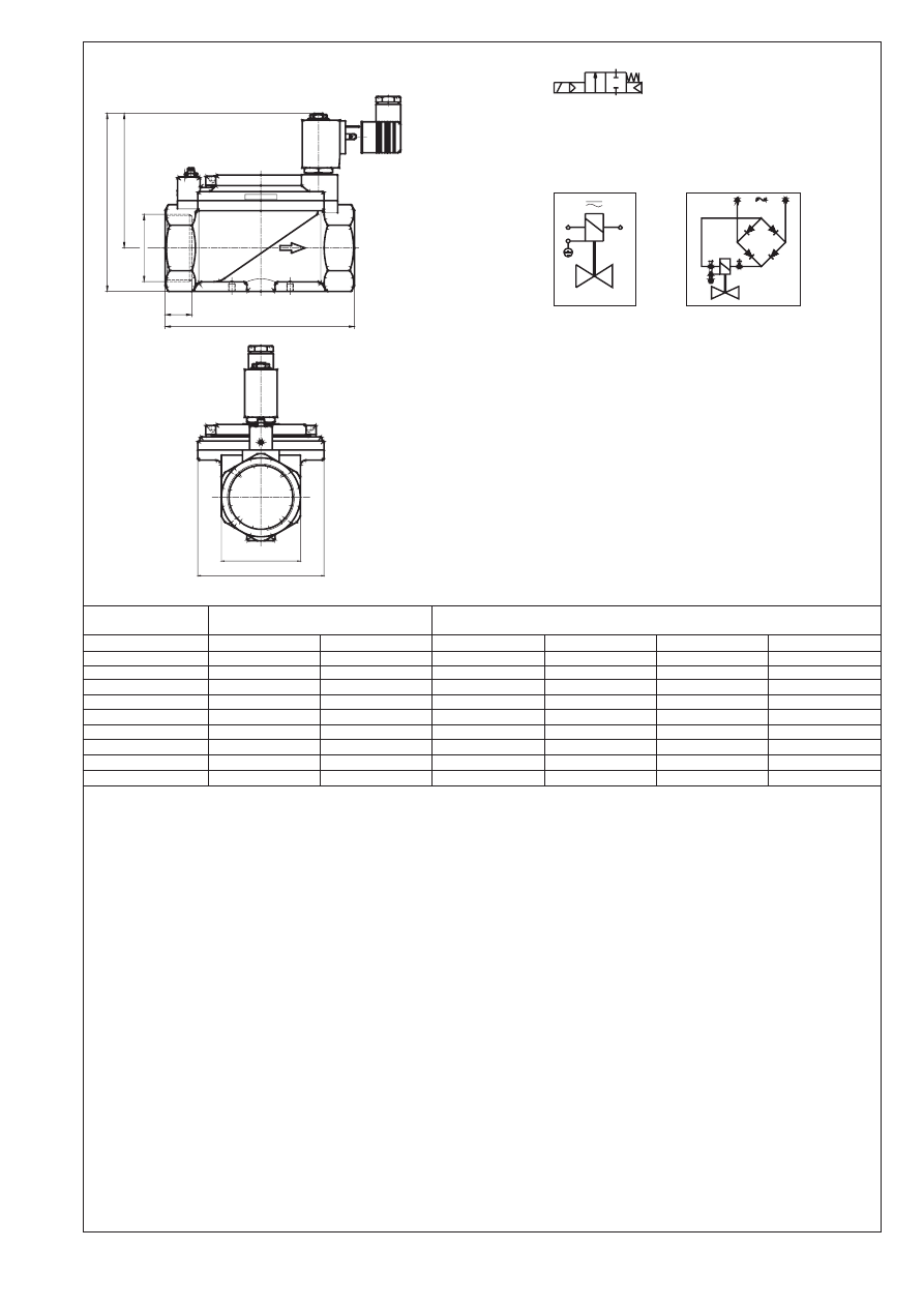
Maßzeichnung Standardausfürung
Dimensional drawing of standard type
Schaltfunktion/Function:
in Ruhestellung gesperrt - NC.
normally closed - NC.
Anschlußplan / Connection diagram
Für Wechsel- und
Gleichspannung.
For AC and DC.
Mit vorgeschaltetem Gleichrichter
für Wechselspannung.
With rectifier for AC connection.
Absicherung entsprechend der Stromaufnahme vorsehen.
Appropiate protection according to the power-consumption.
Ventiloptionen
/
Valve options
Stromlos geöffnet = NO
Handbetätigung = HA
Non energised open = NO
Manual operation = HA
Dichtung = FKM, EPDM
Regulierbare Schließdämpfung (ab G3/4) = SR
Seal = FKM, EPDM
Device for adjustable close damping (from G3/4) = SR
Andere Durchflußmedien und Viskositäten
Öl- und fettfrei = OF
Varying medium and viscosity ranges
Free of oil and grease = OF (for oxygen applications)
Abweichende Temperaturen und Drücke
Buntmetallfrei = BF
Varying temperature and pressure ranges
Free of non-ferrous metal = BF
Stellungsanzeiger (Endschalter ab G3/4) = EH
Temperaturausführung bis +130°C = TM
Position indicator (Reed contact from G3/4) = EH
Design for high temperature up to +130°C = TM
Ex-Schutz = Ex II 2G EEx md IIc T4, T5 oder T6
Abgedichteter Ankerraum = AA
Explosion proof =Ex II 2G EEx md IIc T4, T5 or T6
Sealed plunger = AA
Magnet
Solenoid
.182
.032 / .148 / .012
Type
4021-4023
4024-4025
4021-4023
4024-4025
4026-4027
4028
G
1/4-1/2
3/4-1
1/4-1/2
3/4-1
5/4-6/4
2
A
V.45x45
V.70x70
V.45x45
V.70x70
V.96x96
V.112x112
H
95
106
105
121
143
161
K
75
82
90
97
110
121
L
67
96
67
96
140
168
SW
27
41
27
41
58
70
t
12
16
12
16
22
25
Pg
11
11
11
11
11
11
kg
0,8
1,2
0,8
1,2
2,8
3,9
Erdung oder Schutzschaltung nach Vorschrift des zuständigen EVU.
Grounding or earthing of the protective circuit in accordance with
regulations of the responsible electric supply company.
um 90° umsteckbar
changeable by 90°
H
K
G
t
L
SW
A
A
P
AC,DC
AC
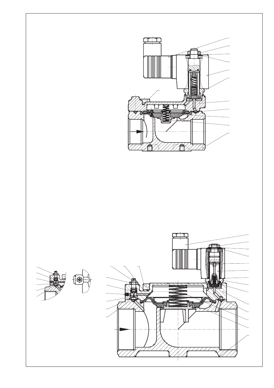
Stückliste - Parts list
K1.1
Armatur / Valve body
K2.1
Deckel / Bonnet
*K3.1
Membrane / Diaphragm
*K3.4
Feder / Spring
K3.10 Verschlußstopfen / Sealing plug
*K3.12 O-Ring / O-ring
K3.13 Dämpfungsschraube / Damping screw
K3.15 Filteraufnahme / Filter retainer
K3.21 Zylinderschraube / Cylinder screw
K3.22 Federring / Lock washer
*K3.23 O-Ring / O-ring
*K3.24 O-Ring / O-ring
K3.25 Filtersieb / Strainer
K3.28 6-kt. Mutter / Hexagon nut
K5.1
Magnethülse / Solenoid tube
K5.2
Magnetanker / Solenoid plunger
K5.3
Feder / Spring
K5.4
Mutter / Nut
K5.5
Wellscheibe / Corrugated disk
K5.6
Dichtung / Seal
K5.7
O-Ring / O-ring
K6.1
Magnet / Solenoid
K7.1
Gerätestecker / Plug
*= Bestandteil des Ersatzteilpäckchens
(je nach Ausführung freibleibend)
*= Part of the service-set.
(The specifications are without obligation)
Baureihe / Type B4026 - B4028
Baureihe / Type D4021 - D4025
Edelstahl und Messingausführung
Stainless steel and brass design
Regulierbare Schließdämpfung - SR (von G5/4-G2 serienmäßig)
Device for adjustable close damping - SR
(From G5/4-G2 standard)
Schraube nach rechts drehen :
Ventil schließt langsamer
Screw to the right site :
Valve closes slower
Schraube nach links drehen :
Ventil schließt schneller
Screw to the left site :
Valve closes - faster
7.1
5.4
5.5
5.7
6.1
5.1
2.1
3.12
3.1
3.4
1.1
3.21
3.28
3.23
3.10
3.15
3.24
3.25
7.1
5.4
5.5
5.7
6.1
5.2
5.6
5.1
5.3
2.1
3.12
3.4
3.1
1.1
3.21
3.22
3.13
3.28
3.23
3.10
3.15
3.24
3.25
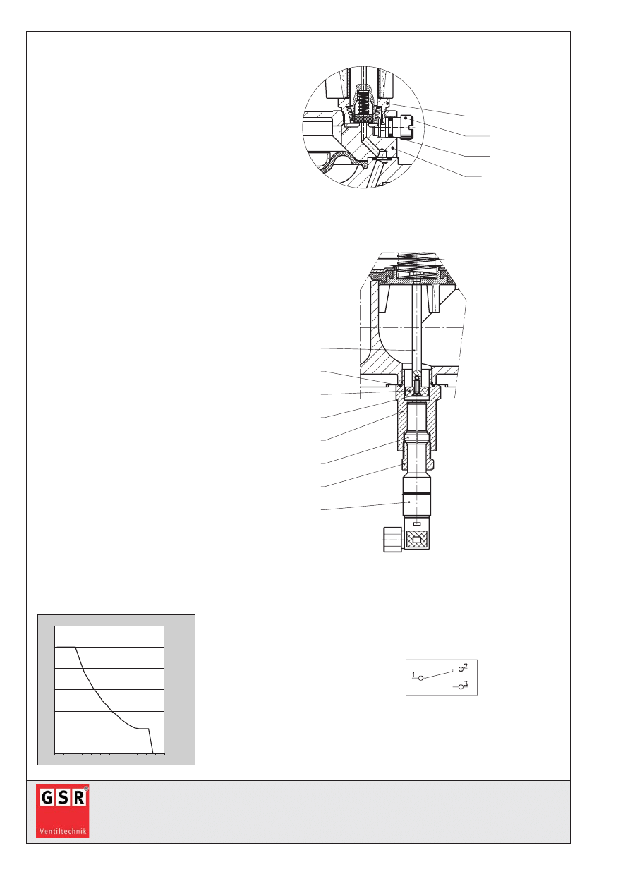
Ventiloptionen / Optional extras
Handbetätigung - HA
Manual operation - HA
K3.62 Spindel / Spindle
K3.65 O-Ring / O-ring
K2.1
Deckel / Bonnet
K5.1
Magnethülse / Solenoid tube
Stellungsanzeiger - EH (ab G3/4)
Position indicator - EH (from G3/4)
K3.75 Zwischenverschraubung / Screw joint
K3.76 Spindel / Spindle
K3.79 O-Ring / O-ring
K3.82 Senkschraube / Countersunk bolt
K3.83 Permanentmagnet / Permanent magnet
K3.84 Klemmring / Clamping ring
K3.85 Verschraubung / Screw joint
K3.86 Endschalter / Position indicator
Anschlußplan
Connection diagram
Endschalter / Position indicator
Schaltleistungsdiagramm
Braking capacity diagram
GSR Ventiltechnik GmbH & Co. KG
Postfach 2060
D-32595 Vlotho
Im Meisenfeld 1
D-32602 Vlotho
Telefon (05228) 779-0
Telefax (05228) 779-190
E-mail: info@ventiltechnik.de
http://www.ventiltechnik.de
5.1
3.62
3.65
2.1
3.76
3.79
3.83
3.82
3.75
3.84
3.85
3.86
0
50
100
150
200
250
300
0,0 0,1 0,2 0,3 0,4 0,5 0,6 0,7 0,8 0,9 1,0 1,1
max. 50VA
V
A

JOWA 3SEP OWS
OILY WATER SEPARATOR
Standard
K:\1-NYA K\1-JOWA PRODUKTER\3SEP\Manual
34/41
10.0 Electrical Drawings and Pneumatic Drawings
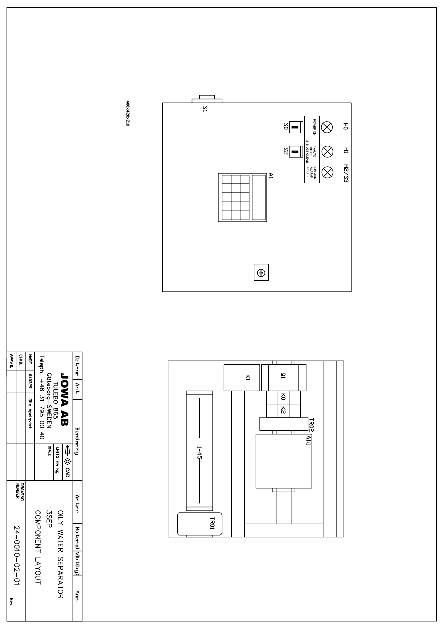
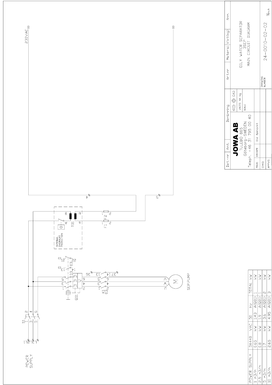
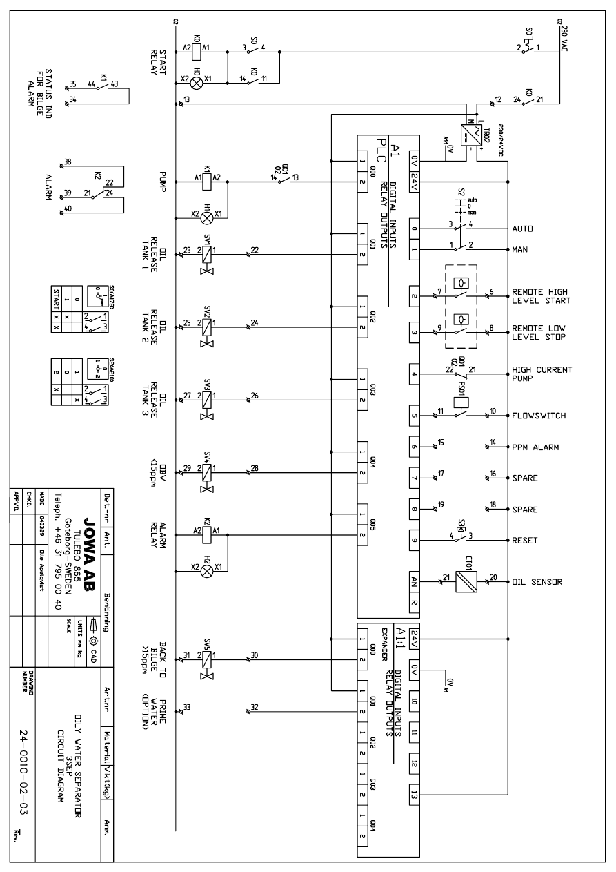
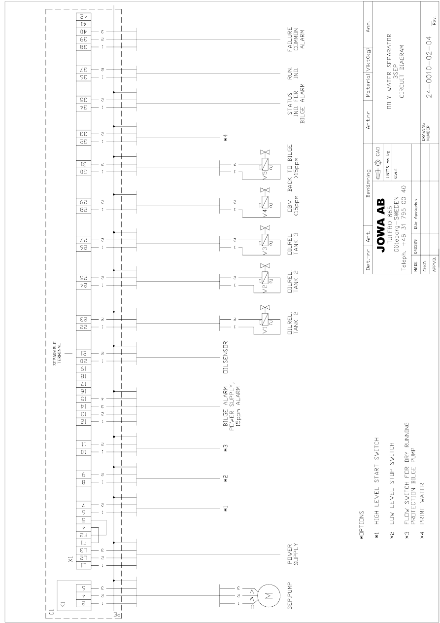
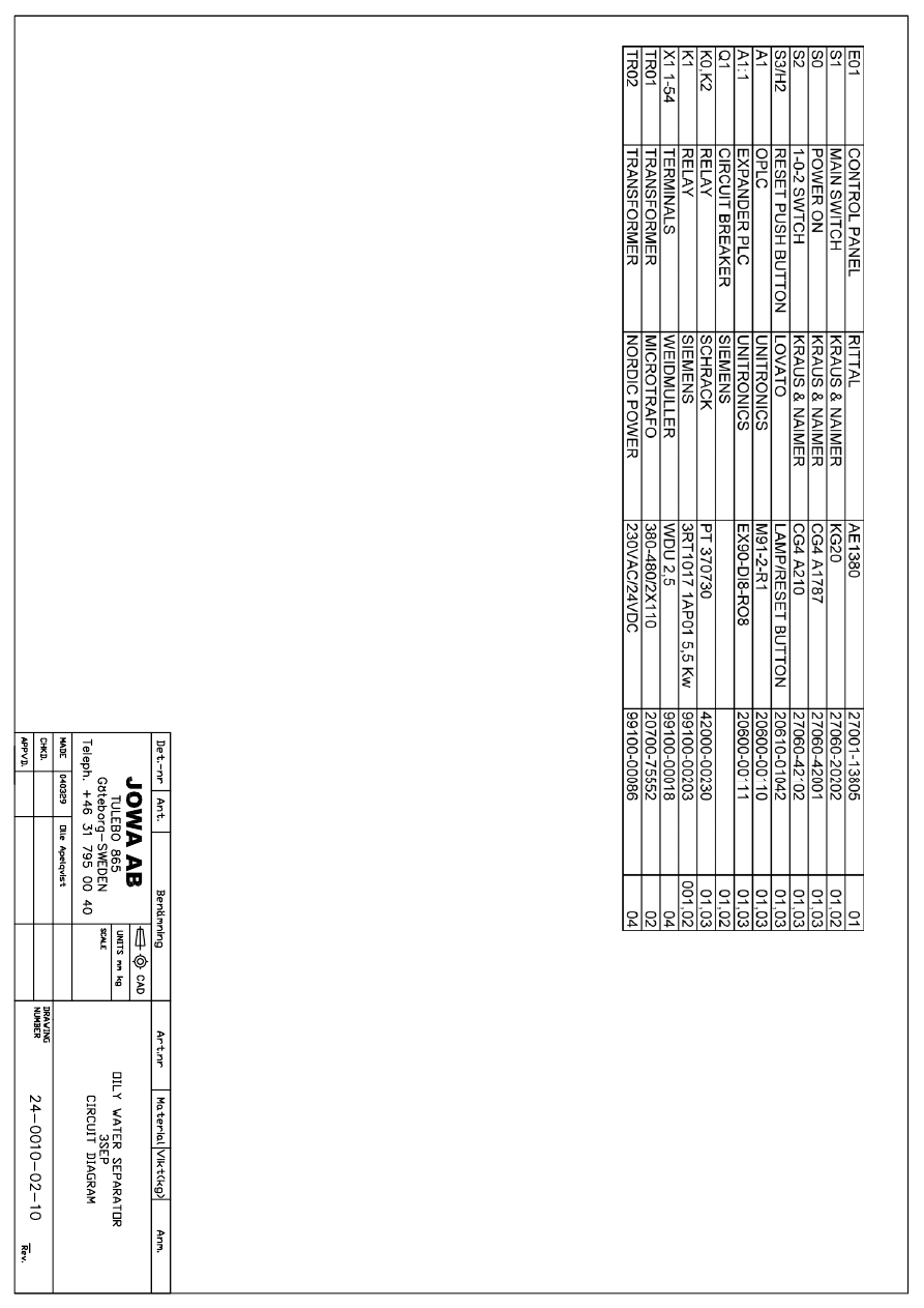
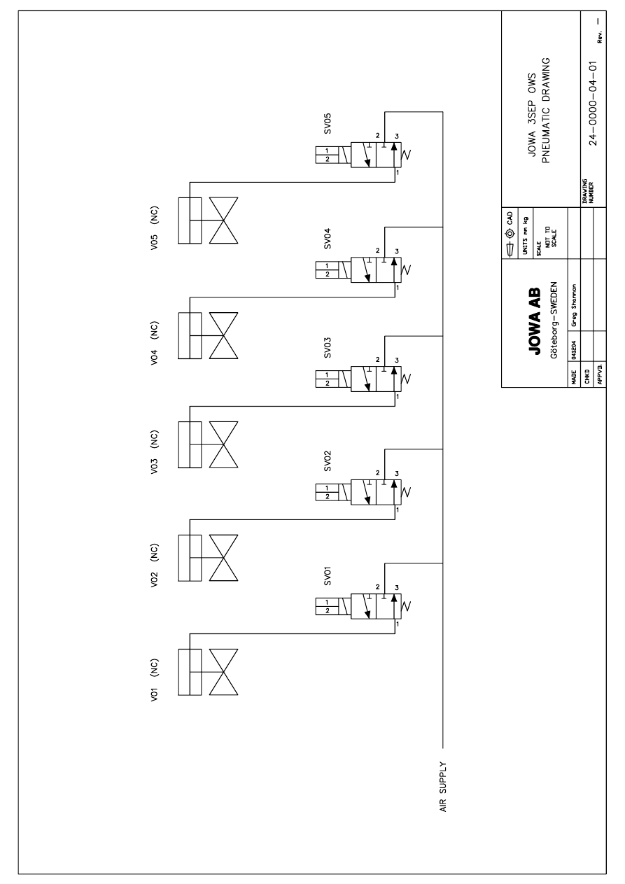

JOWA 3SEP OWS
OILY WATER SEPARATOR
Standard
K:\1-NYA K\1-JOWA PRODUKTER\3SEP\Manual
35/41
11.0 Oil Content Meter Operating Manual
I N S T R U C T I O N M A N U A L
15ppm Bilge Alarm
Type OMD-2005
DECKMA HAMBURG GmbH
Kieler Straße 316, D-22525 Hamburg - Germany
Tel.: +49 (0) 40 54 88 76-0, Fax: +49 (0) 40 54 88 76-10
Internet: www.deckma.com eMail: post@deckma.com

DECKMA HAMBURG GmbH
Issue: 12.11.04
Instruction Manual OMD-2005
Page 2 of 24
IMPORTANT NOTICE
Replacement components for 15ppm Bilge Alarms.
General
All monitors in our range are inspected and tested to the related I.M.O. requirements at
our factories prior to delivery.
In normal use the units should operate correctly and without fault over a long period of
time requiring only small amounts of maintenance to be carried out as outlined in the
instruction manuals.
Service Exchange Units
In the event of a monitor malfunction due to electrical or electronic component failure it
is our recommendation that a service exchange unit be ordered.
The defective instrument should be returned to our works within 30 days of supplying
the service exchange unit, then only the repair charge is payable. Otherwise the whole
cost of a service exchange unit becomes payable.
This procedure is by far the easiest and most cost effective way of ensuring the monitor
on board conforms to I.M.O. resolution MEPC.107 (49).
Remark:
According the MEPC.107(49) § 4.2.11 the unit has to be checked at IOPP Certificate
renewal survey by the manufacturer or persons authorized by the manufacturer.
Alternatively the unit may be replaced by a calibrated 15 ppm Bilge Alarm. The OMD-
2005 is designed in that way, that only the measuring cell needs to be changed, as this
unit carry the calibration onboard. The Calibration Certificate with the date of the last
calibration check should be retained onboard for inspection purposes.
If for some reasons the computer unit needs to be changed, it has to make sure, that
the memory card will remain on board for at least 18 month. The new computer unit will
carry its own memory card. The old card can be insert into the new unit only for reading.
Writing is only possible with the card delivered with the new computer unit. For details
see section 13.1.

DECKMA HAMBURG GmbH
Issue: 12.11.04
Instruction Manual OMD-2005
Page 3 of 24
CONTENTS
SECTION
TITLE
PAGE
1.0
Introduction
4
2.0
Important Notes
4
3.0
Principle of Operation
4
3.1
Measuring Principle
4
3.2
Features
5
3.3
Adjustment
5
3.4
Displays and Alarms
5
4.0
Specification
7
5.0
Construction
8
6.0
Installation
9
7.0
Piping
10
8.0
Wiring
11
8.1
Typical Control System
13
9.0
Power Supply
13
10.0
Commissioning
13
10.1
Electrical
13
10.2
Piping
13
10.3
Functional Tests
14
10.4
Programming Mode
15
11.0
Operating Instructions
17
11.1
Operator Notes
18
12.0
Operator Maintenance
18
12.1
Manual Cell Clean Unit
19
13.0
Fault Finding
20
13.1
Memory Card
21
14.0
Calibration
22
14.1
Calibration and Repeatability Check
22
15.0
Spare Parts
23
15.1
Recommended On Board Spares
23
16.0
Remarks
24

DECKMA HAMBURG GmbH
Issue: 12.11.04
Instruction Manual OMD-2005
Page 4 of 24
1.0
INTRODUCTION
The OMD-2005 Bilge Alarm Unit has been designed specifically for use in
conjunction with 15 ppm oil-water separator units and has a specification and
performance which exceeds the requirements of the International Maritime
Organization specifications for 15ppm Bilge Alarms contained in Resolution
MEPC. 107 (49).
The unit is supplied with 2 works-adjusted alarms at 15 ppm. Other set points
(10 ppm or 5 ppm) are possible and can be adjusted on site at any time by using
the buttons at the front panel.
If an alarm set point is exceed, the alarms are visible at the front panel and the
appropriate relays are switched. In case of malfunction the System LED at the
front panel will change from blinking green to permanent red and the appropriate
relay will switch the contacts.
For the data logging function the unit requires an status input from the separator
and a feedback signal from the valve position limit switch. (See Fig. 1, Pos.6)
Furthermore a 0(4) - 20 mA (equal to 0 - 30 ppm) signal output is available for
driving a recorder or external meter.
2.0
IMPORTANT NOTES
a) This equipment must be installed and operated in strict accordance with the
instructions contained in this manual. Failure to do so will impair the protection
provided.
b) Installation and servicing must be undertaken by a competent and suitable
skilled person.
c) The equipment must be connected to the ground according relevant
requirements.
d) The unit must be isolated from the electrical supply before any maintenance of
the equipment is attempted.
e) All National or local codes of practice or regulations must be observed and,
where applicable, are deemed to take precedence over any directive or
information contained in this manual.
f) In case of freezing conditions the measuring cell should be emptied complete.

DECKMA HAMBURG GmbH
Issue: 12.11.04
Instruction Manual OMD-2005
Page 5 of 24
3.0
PRINCIPLE OF OPERATION
3.1
Measuring Principle
An optical sensor array measure a combination of light scattered and absorbed
by oil droplets in the sample stream. The sensor signals are then processed by a
microprocessor to produce linearised output.
If an alarm (works set point 15 ppm) occurs, the two oil alarm relays are activated
after the adjusted time delay.
The microprocessor continuously monitors the condition of the sensor
components and associated electronics to ensure that calibration accuracy is
maintained over time and extremes of environmental conditions.
3.2
Features
x Robust
construction
x Automatic voltage selection
x Solid suppression capability
x Low
maintenance
x Easy
installation
x Constant
readiness
x Low spare part stock holding
x Watertight
Housing
x Works
adjustment
x Easy settings via menu
3.3
Adjustment
The unit is delivered with a works calibration according the IMO-requirements.
The alarm points are set to 15 ppm.
The "Zero" point is also works calibrated and can be re-adjusted on site by using
the programming mode and clean water. See Section 10.4 “Service-Offset”. A
calibration is not permitted. This has to be done according IMO Regulations by
the manufacturer or persons authorized by the manufacturer.
3.4
Displays and Alarms
In the unit are two independent oil alarm circuits available. Both can be set
separately from 1 to 15 ppm. From the manufacturing both alarms are set to
15 ppm (according IMO). The set points can be changed according to the
requirements on site, for example to 10 ppm or 5 ppm. An alarm point setting
above 15 ppm is not possible. The adjustment can be done in the programming
mode as described in Section 10.4.
In this mode also the individual adjustment of the time delays for the alarms and
the possible changing between 0 - 20 mA or 4 - 20 mA output can be done.

DECKMA HAMBURG GmbH
Issue: 12.11.04
Instruction Manual OMD-2005
Page 6 of 24
Both alarm circuits are also related to an alarm LED on the front panel.
In case of malfunction the “System” LED will indicate any type of internal fault of
the unit. This LED is flashing green in normal conditions and is red in alarm
conditions. Also this alarm is related to an relay output.
Additional to the alarm LED's each alarm circuit is equipped with a relay with
potential free alarm contacts. These contacts can be used for external processing
of the signal or for control of further functions.
If a malfunction or failure of the power supply occurs, all 3 relays will switch to
alarm condition.
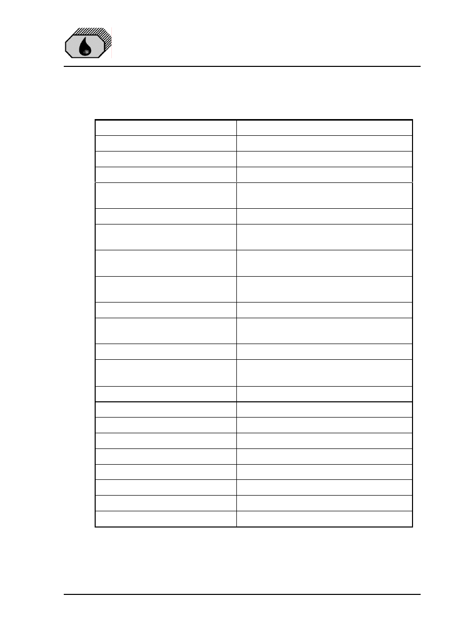
DECKMA HAMBURG GmbH
Issue: 12.11.04
Instruction Manual OMD-2005
Page 7 of 24
4.0
SPECIFICATION OMD-2005
Range:
0 – 30 ppm, Trend up to 50 ppm
Accuracy
According IMO MEPC. 107(49)
Linearity
Up to 30 ppm better than ± 2 %
Display
Green Graphic Display
Power Supply:
24 V – 240 V AC or DC
Automatic Voltage Selection
Consumption:
< 15 VA
Alarm Points 1 + 2:
Adjustable between 1 - 15 ppm
(Works adjustment 15 ppm)
Alarm 1 Operating Delay:
(for annunciation purpose)
Adjustable between 1 – 540 sec.
(Works adjustment 2 sec)
Alarm 2 Operating Delay:
(for control purposes)
Adjustable between 1 – 10 sec.
(Works adjustment 10 sec)
System Fault Alarm:
Red LED
Alarm Contact Rating:
Potential free 1 pole change over
contacts, 3 A / 240 V
Alarm Indication:
Red LED's
Output Signal:
0 – 20 mA or 4 – 20 mA for 0-30 ppm
reversible, ext. Load < 150
:
Sample Water Pressure:
0,1 – 10 bar
Sample Flow:
Approx. 0,1 - 4 l/min depend. to pressure
Ambient Temperature:
+ 1 to + 55° C
Sample Water Temperature:
+ 1 to + 65° C
Roll:
Up to 45°
Size (over all):
360 mm W x 240 mm H x 100 mm D
Degree of Protection:
IP 65
Weight:
7,3 kg
Pipe Connections:
R ¼" Female
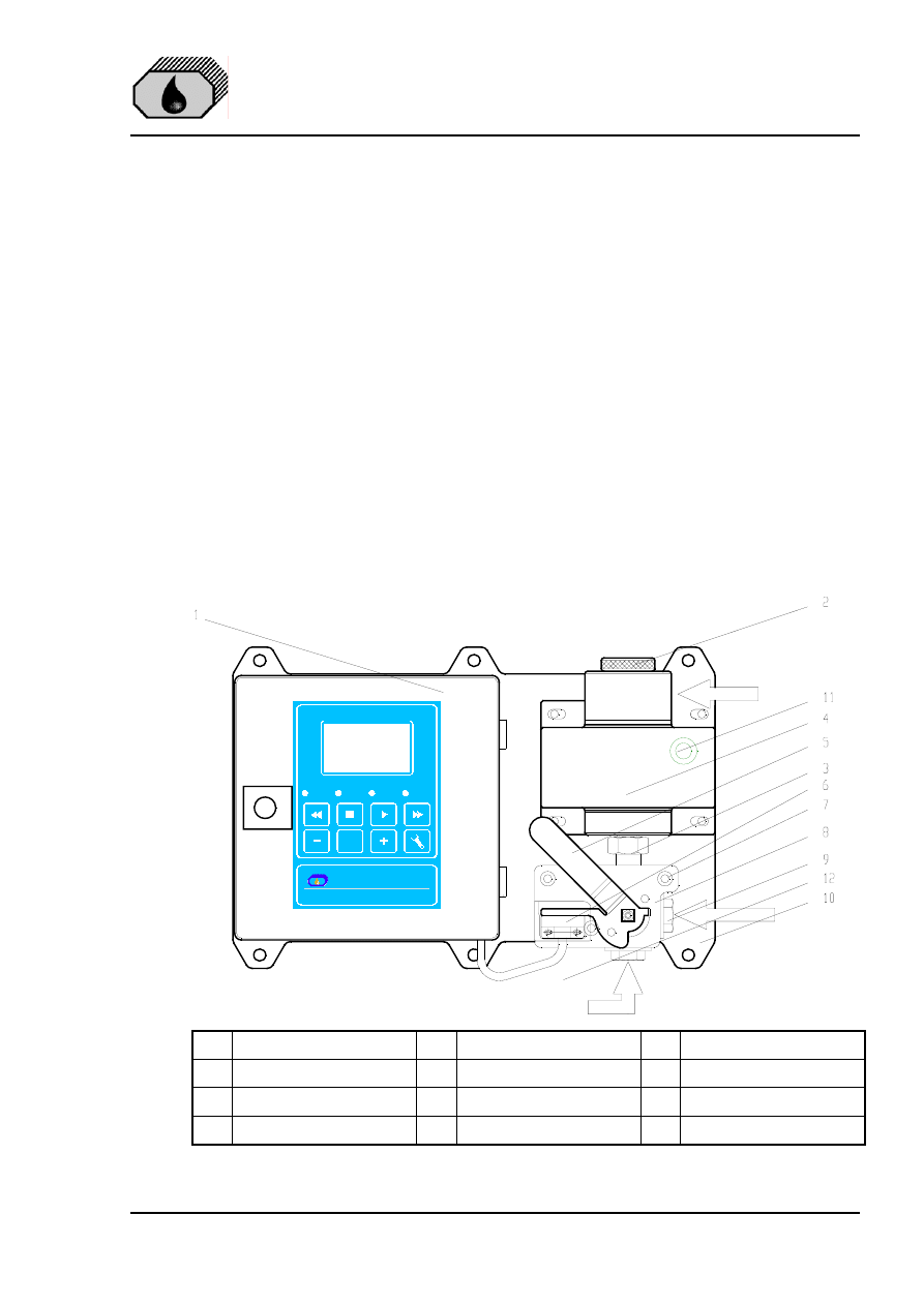
DECKMA HAMBURG GmbH
Issue: 12.11.04
Instruction Manual OMD-2005
Page 8 of 24
5.0
CONSTRUCTION
There are 3 main parts which contained in an OMD-2005:
The computer unit is mounted into an epoxy powder painted steel housing
to protect the electronics of the display PCB with the data logger and the
main board PCB with the terminals for external connections.
The measuring cell is built out of an anodized all-aluminium body with inlet
and outlet block in stainless steel. This rugged cell contains the optical
electronic and correspond with the computer unit via a plugged data cable.
The valve assembly contains a special handle to sense the position of the
valve. This assembly is connected to the measuring cell by an easy to
handle fitting to enable the exchange of the cell for frequently adjustment
according the IMO requirements.
All components are mounted to a stainless steel mounting plate for easy wall or
bulkhead installation. It is also possible to split the computer unit from the
measuring cell if the available space is not sufficient. For this version divided
mounting plates are available.
ON
OMD-2005
Oil Monitoring Device
Alarm 1
Alarm 2
System
OK
DECKMA HAMBURG
www.deckma.com
O U T 1 / 4 "
S A M P L E 1 / 4 "
C L E A N W A T E R 1 / 4 "
DE
CK
MA
HA
MB
UR
G
DH
75
45
0
1
Computer Unit
5
Handle
9
3/2 Way Valve
2
Head Screw
6
Limit Switch
10
Mounting Plate
3
Fitting
7
Spacer
11
Desiccator
4
Measuring Cell
8
Valve Plate
12
Communication Cable
Fig. 1
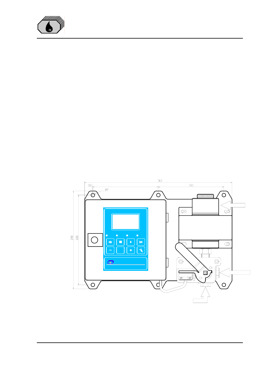
DECKMA HAMBURG GmbH
Issue: 12.11.04
Instruction Manual OMD-2005
Page 9 of 24
6.0
INSTALLATION
(Refer to Fig. 2 and Fig. 3)
See Section 2 for important notes concerning installation.
The OMD-2005 Monitor should be located as close as possible to the oily water
separator to minimize response delays. According MEPC.107(49) the layout of
the installation should be arranged so that the overall response time (including
the response time of the 15 ppm Bilge Alarm) between an effluent discharge from
the 15 ppm Bilge Separator exceeding 15 ppm, and the operation of the
Automatic Stopping Device preventing overboard discharge, should be as short
as possible and in any case not more than 20 s.
Mount the OMD-2005 Monitor by means of 6 x M8 screws on to a rigid vertical
surface and preferably with the display panel of the monitor at eye level. For
service and maintenance sufficient space to all sides should be available.
Care must be taken at mounting of the pipes connections to avoid any torsion of
the housing and damage of the instrument.
ON
OMD-2005
Oil Monitoring Device
Alarm 1
Alarm 2
System
OK
DECKMA HAMBURG
www.deckma.com
O U T 1 / 4 "
S A M P L E 1 / 4 "
C L E A N W A T E R 1 / 4 "
DE
CK
MA
HA
MB
UR
G
DH
75
45
0
Fig. 2
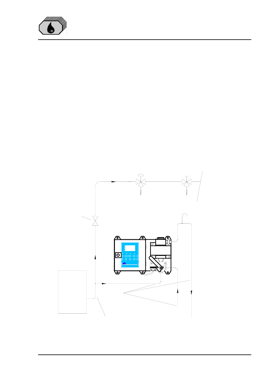
DECKMA HAMBURG GmbH
Issue: 12.11.04
Instruction Manual OMD-2005
Page 10 of 24
7.0
PIPING
(Refer to Fig. 3)
Connect the OMD-2005 Monitor to the sample point of the oily-water separator
outlet and to a source of oil free water employing 10 mm OD copper or stainless
steel pipe. The sample point should be located on a vertical section of the
separator outflow piping to minimize the effects of any entrained air. The tapping
point should be at a level above the outlet of the monitor to ensure the sample
cell is flooded at all times.
If connection to a vertical section of the separator outlet piping is impractical, the
tapping may be made into the side of the horizontal pipe. Avoid top or bottom
entry.
For separator discharge pipes up to 75 mm OD a standard "T"-type junction of
the welded or screwed type is satisfactory for the tapping point. For the separator
discharge pipes of 80 mm OD and above a sample probe should be employed
which protrudes into the discharge piping by approx. 25 % of the ID of the pipe.
Separator
Outlet Separator
Clean Water
Supply (Option)
Outlet
*
10 X 1mm
Copper Tube
Vacuum breaker
Overboard discharge
Pressure relief valve
(if required)
To Bilge
*
Inlet & Outlet connections R1/4" Female
Fig. 3
To Bilge
ON
OMD-2005
Oil Monitoring Device
Alarm 1
Alarm 2
System
OK
DECKMA HAMBURG
www.deckma.com
DE
CK
MA
HA
MB
UR
G
DH
75
45
0
To Bilge
Recirculating
Facilities
Automatic
Stopping Device
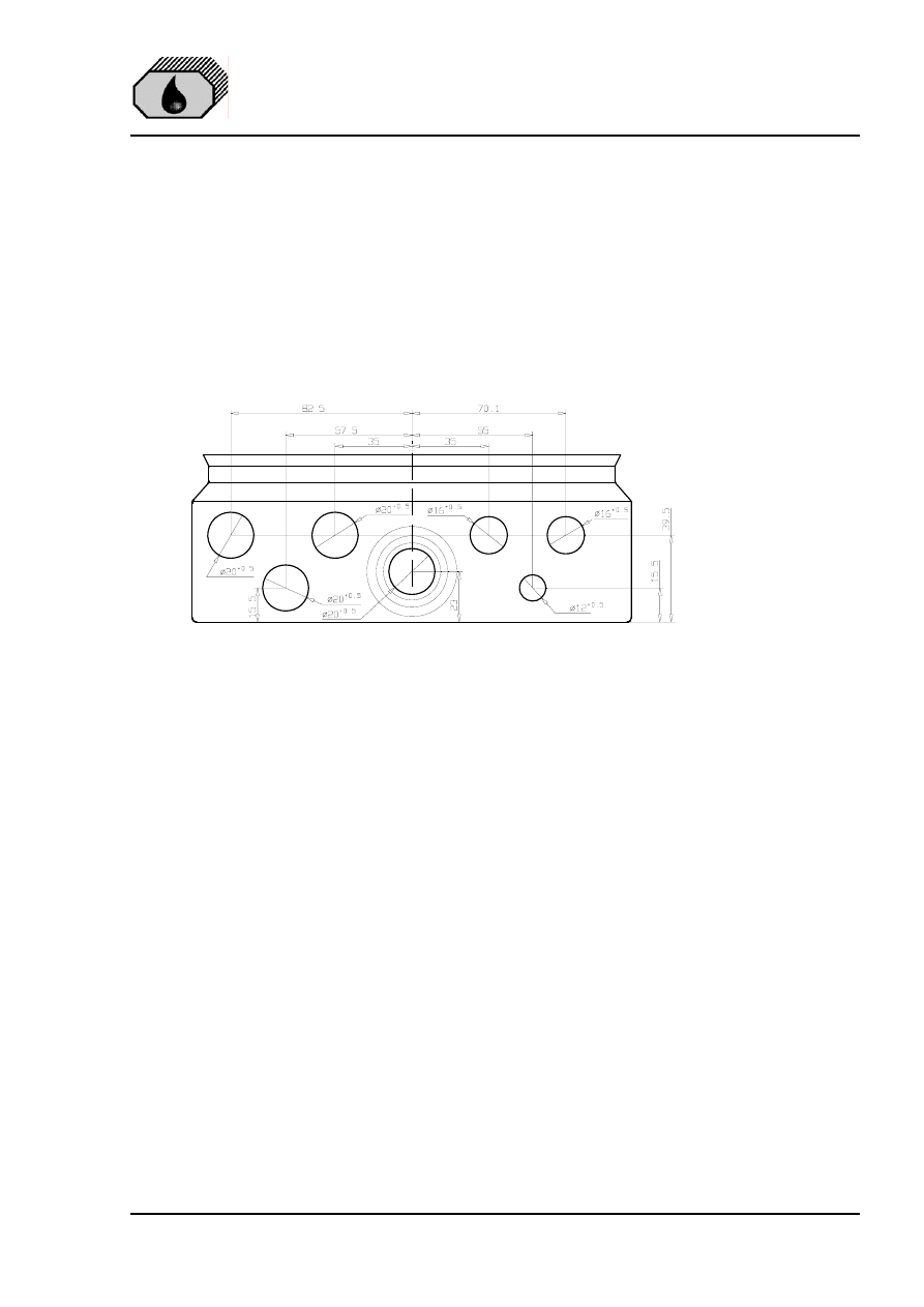
DECKMA HAMBURG GmbH
Issue: 12.11.04
Instruction Manual OMD-2005
Page 11 of 24
8.0
WIRING
(Refer to Fig. 4 + 5)
See Section 2 for important notes concerning wiring.
This unit must be connected to the mains supply via a suitable rated and
approved fused isolator unless such fusing / isolation is provided by associated
equipment. When fitted, the isolator should be close, readily accessible and
marked as to function.
Electrical connections are made through the metric cable gland openings
prepared underneath the instrument.
Fig. 4
Precise wiring details will vary dependent upon the control system to be
employed but the most frequently used systems employ alarm relay 1 for alarm
only and alarm relay 2 for control purposes.
Electrical connections are made to the terminal blocks inside the computer
housing. Wires are connected to the terminals by pushing a suitable screwdriver
into the clamp holes to release the internal spring loaded clamps. After the wire is
inserted to the terminal and the screwdriver is removed, the wire is fixed.
If the instrument is operated at high voltages, additional care has to be taken to
provide reliable ground connections. Ground (PE) can be connected direct to the
terminal or, if this is not sufficient according local rules, to the computer housing
left side. In this case the plug needs to be replaced by a M6 screw with nut and
related washers.
The instrument provides a pilot voltage output at terminals 4&5. This is internally
connected to the power supply input (Terminals 1&2), but is fused by Fuse F1 (2
A). The pilot voltage can be used to supply additional external circuitry, e.g. alarm
lamps or electrical valves.
Please note: any device connected to the pilot voltage output must be rated for
the voltage the instrument is supplied with. Do not use the pilot voltage for driving
motors, heaters or other high load devices. The pilot voltage is intended for alarm
purposes only.
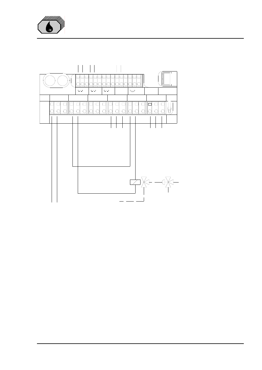
DECKMA HAMBURG GmbH
Issue: 12.11.04
Instruction Manual OMD-2005
Page 12 of 24
Signal Output
0(4)-20 mA
To Alarmsystem
3/2 Way Valve
Automatic Stopping Device
Power Supply
Air Supply
Solenoid Valve
1
2
3
19 20 21 22 23 24 25 26 27 28 29 30 31 32 33
Measuring
Cell
Logger /
Display
F2
F1
Res.
PILOT V
24-240V IN
FLOW
STATUS
RES
OUTPUT
CLEAN
PE
PE
PE
+
-
PE
PE
L
N
PE
4
5
6
PILOT OUT
L
N
PE
7
8
9
A
B
PE
RES
13
14
15
NO
COM
NC
ALARM 2
16
17
18
NO
COM
NC
10
11
12
NO
COM
NC
ALARM 1
SYSTEM FAULT
1A
2A
Contacts shown
in Alarm condition
(de-energised)
Status
Separator
Limit
Switch
To Alarmsystem
(optional)
1-2 Power Supply
4-5 Pilot Voltage Output (Same as Power Supply)
7-8 Spare Voltage Output (Same as Power Supply)
10-12 Potential free Output Alarm 1 (Change over contact)
13-15 Potential free Output Alarm 2 (Change over contact)
16-18 Potential free Output System Fault (Change over contact)
19-20 Input Flow Direction Switch (Deckma Delivery)
22-23 Input Status Switch from Separator (Close when running)
25-26 Input Spare Switch
28-29 Signal Output 0(4) to 20 mA
31-32 Optional Output for Autoclean Valve
EXAMPLE
Connections may vary
with different separator
control boxes
Fig. 5
Close front door complete after electrical installation. Water inside the instrument
may result in corrosion and malfunction.

DECKMA HAMBURG GmbH
Issue: 12.11.04
Instruction Manual OMD-2005
Page 13 of 24
8.1
Typical Control System
The installation on site has to make sure that in case of any loss of power supply
and/or loss of air supply for the automatic stopping device the overboard
discharge valve close the overboard line and open the re-circulating line.
The system showed in the example, employs alarm relay 2 to control a
pneumatic solenoid valve which energises or de-energises a pneumatically
operated 3 - way valve as depicted in Fig. 5.
The separation process will continue until such time as the pollution level falls
below the alarm set point at which time the discharge will be directed overboard.
A pump stop system is according MEPC.107 (49) not allowed.
9.0
POWER SUPPLY
See Section 2 for important notes.
The unit is designed for a power supply of 24 V to 240 V AC or DC. It has an
automatic power selection.
10.0 COMMISSIONING
See Section 2 for important notes.
On completion of the installation, wiring and piping carry out the following checks:
10.1
Electrical
a) Check that the power supply is connected to the terminals 1 + 2 of the
terminal block.
b) Check the wiring of the automatic stopping device and to the alarm system is
according the IMO Requirements.
c) Check that the grounding has been made according to the relevant
regulations.
10.2
Piping
a) Check all piping connections for leaks and rectify as appropriate.
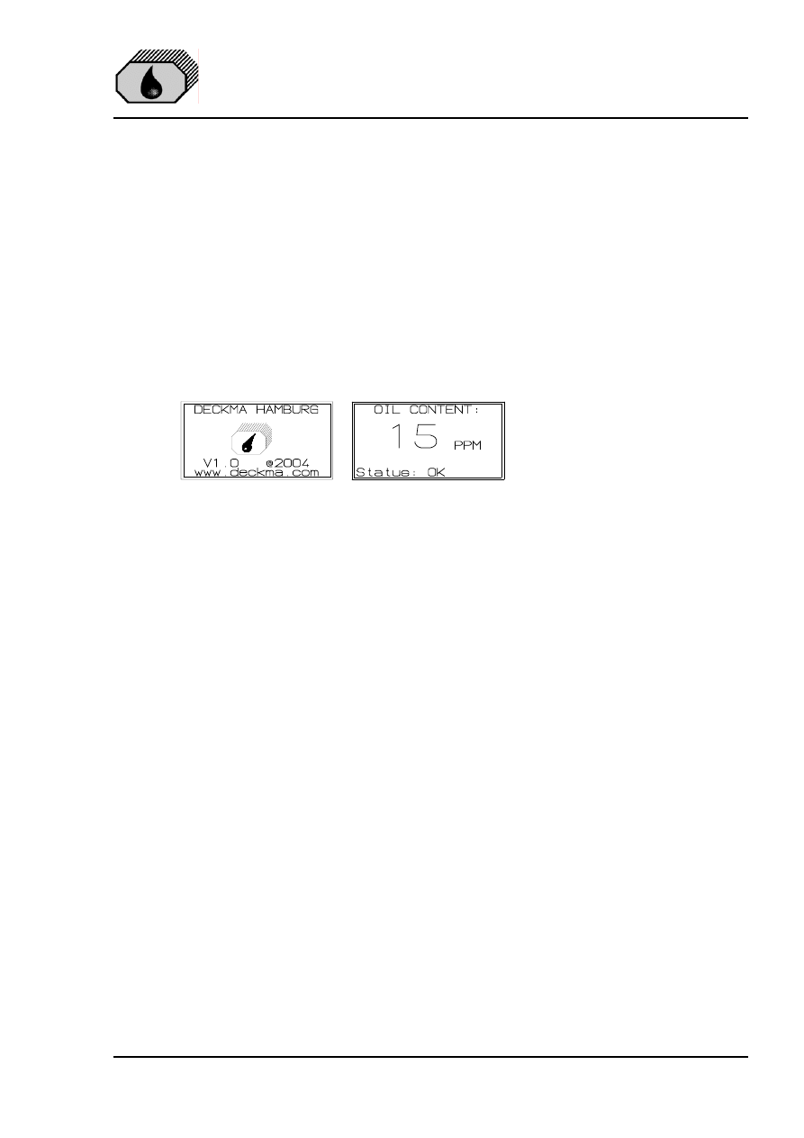
DECKMA HAMBURG GmbH
Issue: 12.11.04
Instruction Manual OMD-2005
Page 14 of 24
10.3
Functional Tests
a) Run oil free water through the instrument to purge the system.
b) Adjust the flow rate through the unit by using the small screws in the cell cap
(Fig. 1, Pos. 2). Taking out a screw will increase the flow rate.
NB: The flow rate should be checked on both, the clean water supply and the
separator sample supply. If the clean water supply is obtained from a high
pressure source, the flow rate will be higher than from the sample point.
The flow rate is not influencing the accuracy of the instrument. The adjustment
is only important for the time delay between the sample point and the monitor.
c) Switch on the instrument and make sure, that the Power LED is illuminated
and the display is showing the
initializing display for about 15
sec. After that time it will
change to the standard display,
showing the actual
measurement.
d) During oil free water is running through the monitor check the Zero adjustment
according Section 11. The display should be "0" to “2” and the status will show
“FW”. If the display varies by greater amounts, it may be that air entrainment is
present. If this is the case, the cause must be located and rectified.
f) If the Zero need to be adjusted, this can be done in the programming mode as
described in section 10.4. (Service – Offset)
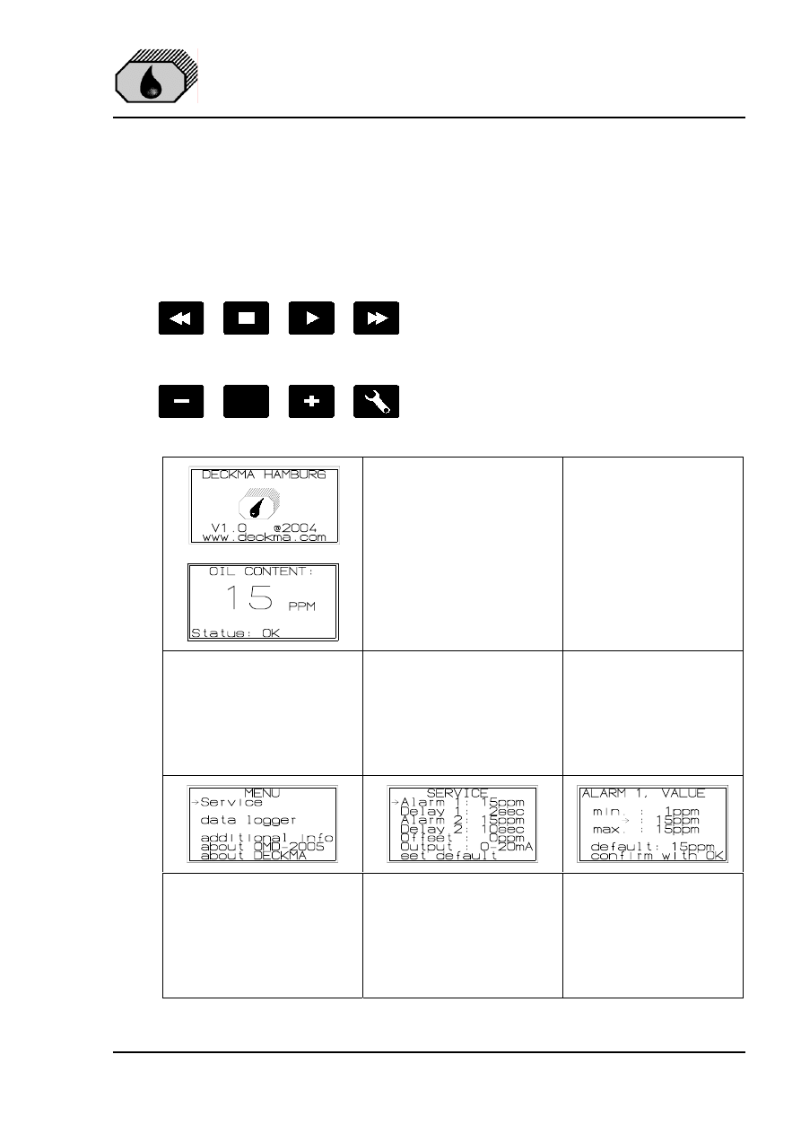
DECKMA HAMBURG GmbH
Issue: 12.11.04
Instruction Manual OMD-2005
Page 15 of 24
10.4
Programming Mode
In the programming mode the alarm set points, the time delays, the signal output
and the zero can be modified. It is also possible to recall the factory default
values at any time. The clock is
factory set for GMT, Greenwich Mean
Time, and cannot be changed.
There are 8 push buttons to control
the functions of the display. In general
are the upper buttons for the data
logger and the lower buttons for
changing the display to the different
pages of the menu.
Pressing the OK button will give
more detailed information about
the status
After start the display will show
the initial display followed by
the actual measured oil content.
This display also be shown, if
no input at the different menu’s
has been done for a designated
time
To get into the menu press the
tool button. Select the required
point by using the „+“ or „-„
button. Press the „OK“ button.
At the service menu the alarms,
time delays, the Offset and the
output signal can be modified
within the limitations. Select the
required point by using the „+“
or „-„ button. Press the „OK“
button.
To change the value, press
the “+” or “-“ button. Confirm
with “OK”.
OK
Do
ub
le
Ar
ro
w
ba
ck
En
te
r
Ar
ro
w
fo
rw
ar
d
Do
ub
le
Ar
ro
w
fo
rw
ar
d
"-"
Bu
tto
n
"O
K"
Bu
tto
n
"+
" B
ut
to
n
To
ol
Bu
tto
n
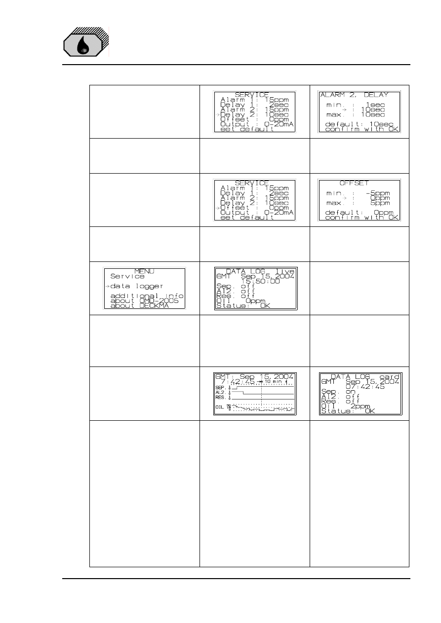
DECKMA HAMBURG GmbH
Issue: 12.11.04
Instruction Manual OMD-2005
Page 16 of 24
Select the required point by
using the „+“ or „-„ button.
Press the „OK“ button.
To change the value, press
the “+” or “-“ button. Confirm
with “OK”.
Select the required point by
using the „+“ or „-„ button.
Press the „OK“ button.
To change the value, press
the “+” or “-“ button. Confirm
with “OK”.
To get into the menu press the
tool button. Select the required
point by using the „+“ or „-„
button. Press the „OK“ button.
The display will show the actual
status of the data logger. To get
back to the standard display
press the tool button or the OK
button.
Function of the scrolling buttons
for both operation time history
displays:
>
15 sec Forward
> and +
2 min Forward
>>
Fast Forward
>> and +
Very Fast Forward
-
15 sec Backward
< and +
2 min Backward
<<
Fast Backward
<< and +
Very Fast Backward
Press the “Enter” button to get
into the history. Select the
required date and time by using
the buttons.
The dotted vertical line shows
the actual position.
Press the “Enter” button to
show details
The detailed information of
the selected date and time
will be displayed. To get
back to the history graph,
press the “Enter” Button
again. To get back to the
start display, press the “OK”
button.
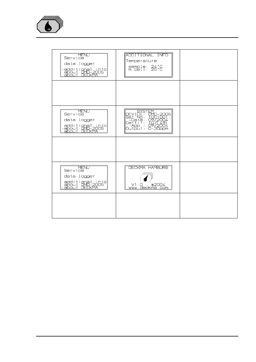
DECKMA HAMBURG GmbH
Issue: 12.11.04
Instruction Manual OMD-2005
Page 17 of 24
To get into the menu press the
tool button. Select the required
point by using the „+“ or „-„
button. Press the „OK“ button.
The temperature of the
measuring cell and the sample
water will be shown
To get into the menu press the
tool button. Select the required
point by using the „+“ or „-„
button. Press the „OK“ button.
The details of the measuring
cell will be shown.
To get into the menu press the
tool button. Select the required
point by using the „+“ or „-„
button. Press the „OK“ button.
Information about the software
version and the web address
will be shown.
NB: All changed values have to be confirmed by pressing the " OK " button.
Otherwise the existing values are valid.
11.0 OPERATING INSTRUCTIONS
a) Switch on the power supply.
b) Allow a period of time for water entering the sample tube.
c) Flow oil free water through the system for a few minutes and check that the
display show 0 to 2 ppm. If not, clean proper before adjusting the unit
according section 10.4 “Service - Offset”.
d) Switch the instrument sample supply from the clean water supply to the
separator sampling point connection.
e) The instrument is now ready for use.

DECKMA HAMBURG GmbH
Issue: 12.11.04
Instruction Manual OMD-2005
Page 18 of 24
11.1
Operator Notes
a) When oily water flows through the instrument the display will show the actual
value of oil content.
b) If the oil concentration exceeds the adjusted threshold (works adjustment
15 ppm), the alarm indicator 1 will be illuminated in intervals during the
selected time delay before it change to steady light and the associated alarm
relay will operate. Accordingly also the alarm indicator 2 will be illuminated
and its associated alarm relay will take the appropriate shut down action.
12.0 OPERATOR MAINTENANCE
See Section 2 for important notes.
AT WEEKLY INTERVALS:
a) Flush the cell with oil free water.
b) Isolate the instrument from both, sample and oil free water supply.
c) Unscrew and remove the cell cap.
d) Insert a suitable Cell Cleaning brush (Art. No. 30102) into the cell and clean it
with upwards and downwards motion through the entire length of the cell
several times.
e) Remove the Cell Cleaning brush and replace the cell cap.
f) Reconnect the oil free water supply and allow this to flow through the
instrument for a few minutes.
g) Observe that the display is showing "0" to “2”. If not, clean again.
h) Examine the color of the desiccator (Fig. 1, Pos. 11). Blue color is indicating
an active moisture absorber. If the color is light blue or white, the desiccator
should be replaced.
The desiccator assures a humidity below 40% inside the measuring cell to
avoid wrong measurement resulting due to condensation at the cell glass tube
and damage of the electronics around the glass tube. The replacement is easy
done without opening the instrument. Just unscrew the old desiccator out of
the front panel and replace it by a new one. The protection cap of the spare
unit can be also used as a tool.
j) Reconnect the instrument to the separator sampling point.

DECKMA HAMBURG GmbH
Issue: 12.11.04
Instruction Manual OMD-2005
Page 19 of 24
12.1
Manual Cell Clean Unit
Optional item if fitted
This unit facilitates cleaning of the cell without the need of removing the cell cap.
Regular use of this device should prevent malfunction of the monitor due simply
to fouling of the sample tube and all the inconvenience which this can cause.
Operating Instructions
a) Ensure that the monitor is switched off and that there is a clean water supply
through the cell.
b) Activate the manual cell clean unit by pressing the handle several times.
c) Switch the monitor back on and check the reading is between 0 to 2 ppm.
d) Repeat a) to c) at least once a week or as necessary.
NB: The Manual Cell Clean Unit may also be used during normal operation with
sample water, but in this case an alarm occurs because the wiper is passing the
light source.
Spares: Wiper Seal, Part. No. 30605

DECKMA HAMBURG GmbH
Issue: 12.11.04
Instruction Manual OMD-2005
Page 20 of 24
13.0 FAULT FINDING
See Section 2 for important notes.
The OMD-2005 will indicate several malfunctions in the status line of the display.
Pressing the “OK” button will lead into an information window, similar to the items
listed in the table below.
Status
Reading
System-Alarm-
circuit
Alarm-
circuit 1,2
Reason
Servicing
LED
Alarm
OK
0..49
Green /
Blinking
No
Normal
operation
Normal operation
-
OK
EE
Green /
Blinking
No
Alarm
Sample reading is out
of range:
Oil content too high,
dirty sample tube
Wait until oil content is
within the range,
clean sample tube
FW !
0..49 / EE Green /
Blinking
No
Alarm
Freshwater is enabled
-
Sample?
EE
Red /
Steady
Yes
Alarm
Meter is not able to
measure the sample:
no water in, oil content
much too high, no light
transmission possible
Check sample, clean
sample tube
Com?
EE
Red /
Steady
Yes
Alarm
No communication
between computer unit
and measuring cell
Check connection
between computer
unit and measuring
cell
Datalogging is not
possible:
no DECKMA card in
Insert the active
memory card
Datalogging is not
possible:
a read only card is in
Insert the active
memory card
Datalog?
0..49 / EE Red /
Steady
Yes
Alarm
Datalogging is not
possible:
a new DECKMA card is
in
Activate card or insert
the active memory
card
Int.Err
Red /
Steady
Yes
Alarm
Internal error
Restart the system
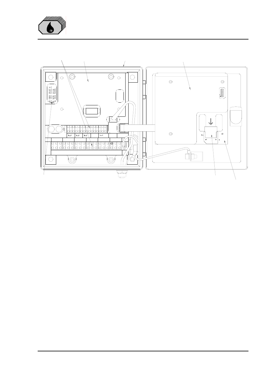
DECKMA HAMBURG GmbH
Issue: 12.11.04
Instruction Manual OMD-2005
Page 21 of 24
1
2
3
19 20 21 22 23 24 25 26 27 28 29 30 31 32 33
Measuring
Cell
Logger /
Display
F2
F1
PILOT VOLT.
POWER
24-240V IN
FLOW
STATUS
RES
OUTPUT
CLEAN
PE
PE
PE
+
-
PE
PE
L
N
PE
4
5
6
PILOT OUT
L
N
PE
7
8
9
A
B
PE
RES
13
14
15
NO
COM
NC
ALARM 2
16
17
18
NO
COM
NC
10
11
12
NO
COM
NC
ALARM 1
SYSTEM FAULT
Protection Cover
Display PCB
Terminals
Main PCB with Holder
Computerhousing
Display PCB
Memory
Card
Status LED's:
D7
Power ON
D11
Microprocessor (blinking)
D12
Measuring Cell (blinking)
D13
Display (blinking)
D14
Spare
D19
Alarm 1 OFF
D20
Alarm 2 OFF
D21
System Fault OFF
D22
Spare
D15
Status Separator
D16
Status Water Supply
D17
Spare
D18
Status Datalogger
D23
Alarm 1 ON
D24
Alarm 2 ON
D25
System Fault ON
D26
Spare
Fig. 6
13.1
Memory Card (refer to Fig. 6)
The Memory Card is located inside the door of the computer housing. It is
suitable for the life of the instrument, as it is calculated to the according MEPC
107(49) required storage time of at least 18 month. When the card is full, the
oldest entry will be overwritten, so that a replacement is not necessary. Under
normal use the card should not be taken out, as this is linked with the specific
system. The card can be read in other OMD-2005 units, but writing is only
possible in the related system.

DECKMA HAMBURG GmbH
Issue: 12.11.04
Instruction Manual OMD-2005
Page 22 of 24
14.0 CALIBRATION
15 ppm Bilge Alarms built according MEPC.107(49) have to be protected against
access beyond the checks of instrument drift, repeatability of the instrument
reading and zero adjustment. For this reason the instrument is electronically
sealed, so that only the manufacturer or his authorized persons, equipped with
the related tools, are able to get access for changing the calibration.
To provide a simple procedure for check the instrument aboard ship, the OMD-
2005 is constructed in that way, that the zero check also confirms the instrument
drift within the specifications.
14.1
Calibration and repeatability check
a) Switch off the power supply and stop any water flow.
e) Clean the sample tube accurate by using a suitable cell cleaning brush as
described under Section 12.0. Make sure, that the offset is correct at ± 0.
f) Run clean water through the instrument.
g) If it is sure, that non aerated, clean water is in the instrument, the reading
should be 0 ppm ± 2 ppm.
a) Continue as described under Section 11.0.
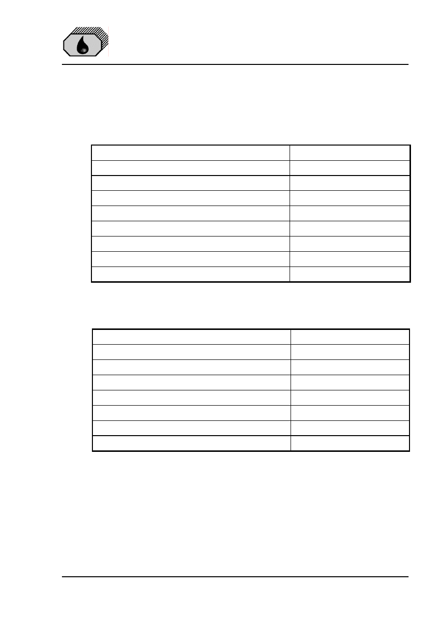
DECKMA HAMBURG GmbH
Issue: 12.11.04
Instruction Manual OMD-2005
Page 23 of 24
15.0 SPARE PARTS
When ordering spares, it is important to supply details of the type of monitor, part
number of each spare required, its description and any relevant serial number.
DESCRIPTION
ART-NUMBER
Desiccator
65550
Cell Cleaning Brush
30102
O-Ring Set
75775
Fuse, T 2 A
40107
Fuse, T 1 A
Measuring Cell with Calibration Certificate
75500/17500
15.1
Recommended On Board Spares
2 off Desiccator
65550
1 off Cell Cleaning Brush
30102
1 off O-Ring Set
75775
2 off Fuse T 2 A
40107
Optional item
1 off Manual Cell Clean Unit

DECKMA HAMBURG GmbH
Issue: 12.11.04
Instruction Manual OMD-2005
Page 24 of 24
16.0 REMARKS
All the modifications and deviations from the standard form, which have to be
carried out in the supply, should be attached at this paragraph.
Commissioned on: .............................
by: ..........................................
Date
Firm's Name
Remarks:

JOWA 3SEP OWS
OILY WATER SEPARATOR
Standard
K:\1-NYA K\1-JOWA PRODUKTER\3SEP\Manual
36/41
12.0 1.0m3/h and 2.5m3/h Pump Operating Manual
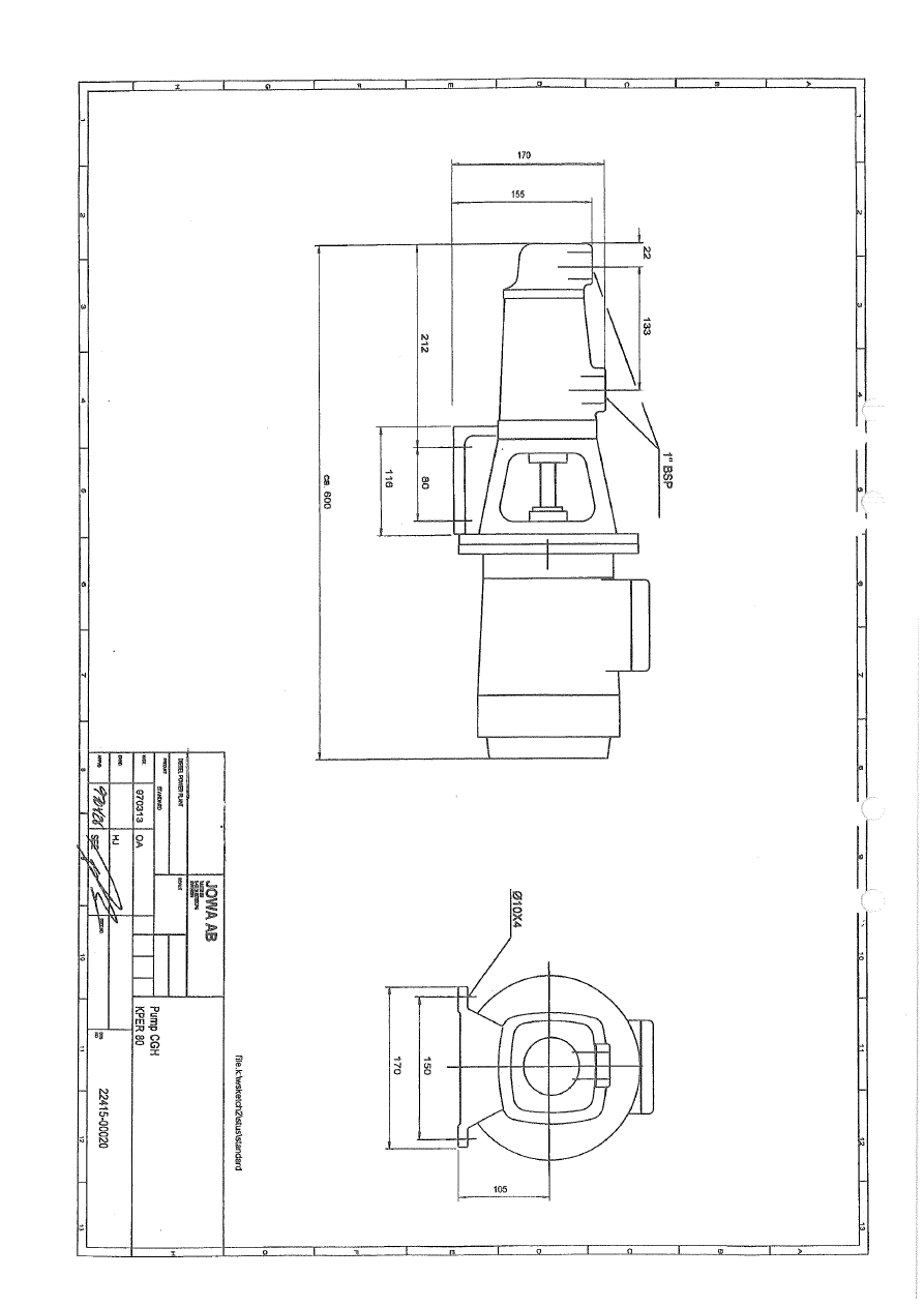
Wyszukiwarka
Podobne podstrony:
JOWA 3 SEP OWS Manual + deckmaRev Oil content meter 2
JOWA 3 SEP OWS Manual
JOWA 3 SEP OWS Pump Mono
JOWA 3 SEP OWS Pump Mono
JOWA Bio STP manual STP 2 revB
06 INSTRUCTION MANUAL FUEL OIL FILTER 12153 3188 E
2601 Manual transmission oil change
07 INSTRUCTION MANUAL LUB OIL FILTER 12153 3204
Jowa OWS 15ppm bilge alarm new
JOWA OWS Diagram
Jowa OWS 15ppm bilge alarm new 15
Jowa OWS 15ppm bilge alarm new
09 INSTRUCTION MANUAL OIL PUMP 12143 3055 E
2610 Manualo transmission, checking & correcting oil level
więcej podobnych podstron