
JOWA 3SEP OWS
OILY WATER SEPARATOR
Standard
K:\1-NYA K\1-JOWA PRODUKTER\3SEP\Manual
37/41
13.0 5.0m3/h Pump Operating Manual
Mono
®
Installation, Operation and
Maintenance Instructions
Monobloc B Range
Sizes: B012, B014, B021, B022, B024
B031, B03K, B032, B0X1, B0X2
OMMP/010/01/R21
English

Spares and Service Contact Details
Spares & Service
Issued - January 2005
Mono UK
Spares
+44 (0)161 214 2380 (direct line 8.15 am – 5.00 pm)
spares@mono-pumps.com
Service
+44 (0)161 214 2390 (direct line 8.15 am – 5.00 pm)
customerservices@mono-pumps.com
Service
+44 (0)161 339 9000 (24 hrs)
Mono Australia
Telephone
Facsimile
Melbourne
(03) 9580 5211
(03) 9580 9036
Sydney
(02) 9521 5611
(02) 9542 3649
Brisbane
(07) 3350 4582
(07) 3350 3750
Adelaide
(08) 8447 8333
(08) 8447 8373
Perth
(08) 9479 0444
(08) 9479 0400
Darwin
(08) 8984 3099
(08) 8947 0540
Tasmania
(03) 6249 8704
(03) 6249 8756
ozsales@mono-pumps.com
Mono New Zealand
Spares & Service
+64 (0)9 829 0333
info@mono-pumps.co.nz
Monoflo USA
Spares & Service
+1 713 466 7999
inquire@monoflo.com
Mono China
Telephone
Facsimile
Beijing
+86 (0) 10 6461 1115
+86 (0) 10 8486 8481
Shanghai
+86 (0) 21 5915 7168
+86 (0) 21 5915 6863
info@mono-pumps.com

ATEX Warning Statements
ATEX - Page 1 of 2
Issued - February 2004
Reference - OMMP/028/01/R1
PUMPS AND PUMP UNITS
x
Where a pump or pump unit is to be installed in a
potentially explosive atmosphere ensure that this has
been specified at the time of purchase and that the
equipment has been supplied accordingly and
displays an ATEX nameplate or is supplied with a
certificate of conformity. If there is any doubt as to the
suitability of the equipment please contact Mono
Pumps Limited before commencing with installation
and commissioning.
x
Process liquids or fluids should be kept within
specified temperature limits otherwise the surface of
pump or system components may become an ignition
source due to temperature rises. Where the process
liquid temperature is less that 90ºC the maximum
surface temperature will not exceed 90ºC provided
the pump is installed, operated and maintained in
accordance with this manual. Where the process fluid
temperature exceeds 90ºC the maximum surface
temperature will be equal to the maximum process
fluid temperature.
x
Cavities that could allow the accumulation of
explosive gases, such as under guards, should where
possible, be designed out of the system. Where this is
not possible they should be fully purged before any
work is carried out on the pump or system.
x
Electrical installation and maintenance work should
only be carried out by suitably qualified and
competent persons and must be in accordance with
relevant electrical regulations.
x
All electrical equipment, including control and safety
devices, should be suitably rated for the environment
in to which they are installed.
x
Where there may be a risk of an accumulation of
explosive gases or dust non-sparking tools should be
used for installation and maintenance.
x
In addition to causing permanent damage to the
stator, dry running of the pump could generate a rapid
rise in the temperature of the stator tube or barrel,
which could become an ignition source. It is therefore
essential that a dry run protection device be fitted.
This must shut the pump down immediately should a
dry run situation occur. Details of suitable devices are
available from Mono Pumps Limited.
x
To minimise the risk of sparking or temperature rises
due to mechanical or electrical overload the following
control and safety devices should be fitted in addition
to a dry run protection system. A pressure relief
system whereby the pump can not generate
pressures in excess of the maximum rated pressure
or an over pressure device which should shut the
pump down when the maximum discharge pressure is
exceeded. A control system that will shut the pump
down if the motor current or temperature exceed
specified limits. An isolator switch that will disconnect
all electrical supply to the motor and ancillary
electrical equipment and be capable of being locked
in the off position. All control and safety devices
should be fitted, operated and maintained in
accordance with the manufacturer’s instructions. All
valves on the system should be open when the pump
is started otherwise serious mechanical overload and
failure may result.
x
It is important that the pump rotates in the direction
indicated on the nameplate. This must be checked on
installation and commissioning and after any
maintenance has been carried out. Failure to observe
this may lead to dry running or mechanical or
electrical overload.

ATEX Warning Statements
ATEX - Page 2 of 2
Issued - February 2004
Reference - OMMP/028/01/R1
x
When fitting drives, couplings, belts, pulleys and
guards to a pump or pump unit it is essential that
these are correctly fitted, aligned and adjusted in
accordance with the manufacturer’s instructions.
Failure to do so may result in sparking due to
unintended mechanical contact or temperature rises
due to mechanical or electrical overload or slipping of
drive belts. Regular inspection of these parts must be
carried out to ensure they are in good condition and
replacement of any suspect part must be carried out
immediately.
x
Mechanical seals should be suitably rated for the
environment. The seal and any associated
equipment, such as a flushing system, must be
installed, operated and maintained in accordance with
the manufacturer’s instructions.
x
Where a packed gland seal is fitted this must be
correctly fitted and adjusted. This type of seal relies
on the process liquid to cool the shaft and packing
rings so a constant drip of liquid from the gland
section is required. Where this is undesirable an
alternative seal type should be fitted.
x
Failure to operate or maintain the pump and ancillary
equipment in line with the manufacturer’s instructions
may lead to premature and potentially dangerous
failure of components. Regular inspection, and where
necessary replacement, of bearings and lubrication is
essential.
x
The pump and its components have been designed to
ensure safe operation within the guidelines covered
by legislation. Accordingly Mono Pumps Limited have
declared the machine safe to use for the duty
specified as defined by the Declaration of
Incorporation or Conformity that is issued with this
instruction manual.
The use of replacement parts that are not
manufactured by or approved by Mono Pumps Limited
may affect the safe operation of the pump and it may
therefore become a safety hazard to both operators
and other equipment. In these circumstances the
Declaration provided will become invalid. The
guarantee referenced on the Terms and Conditions of
Sale will also be invalidated.
Index
Index
Issued - November 2004
SECTION 1
INSTALLATION
START-UP PROCEDURE
ASSEMBLY AND DISMANTLING ADVICE
SECTION 2
FAULT FINDING
SECTION 3
DRAWING REFERENCE NUMBERS
PUMP CODING SHEET
SECTION 4
DISMANTLING AND ASSEMBLY DIAGRAMS
EXPLODED VIEWS
SECTION 5
TORQUE TIGHTENING FIGURES
SECTION 6
MONO PRODUCTS
EC Declaration
as defined by Machinery Directive 98/37/EC.
EC Declaration of Incorporation
This declaration is only valid when the machinery has
been supplied without drive unit.
In this case, the machinery meets the requirements of the
said directive and is intended for incorporation into other
machinery or for assembly with other machinery in order
to constitute relevant machinery as defined by the said
directive including any amendments, which are valid at the
time of supply.
IMPORTANT
This machinery must not be put into service until the
relevant machinery into which it is to be incorporated has
been declared in conformity to the said directive.
This declaration is only valid when the machinery has
been installed, operated and maintained in accordance
with these instructions and safety guidelines contained
within as well as instructions supplied for equipment
assembled with or intended for use with this equipment.
The following harmonised standards are applicable:
BS EN 809
BS EN 12100 Parts 1 & 2
EC Declaration of Conformity
This declaration is only valid when the machinery has been
supplied with drive unit.
In this case the machinery meets the requirements of the
said directive including any amendments which are valid at
the time of supply.
IMPORTANT
This declaration is only valid when the machinery has been
installed, operated and maintained in accordance with these
instructions and safety guidelines contained within as well
as instructions supplied for equipment assembled with or
intended for use with this equipment.
Mr G.D. Thomas, Chief Engineer

Installation, Operation & Maintenance Instructions
Section 1, Page 1
Issued - December 2002
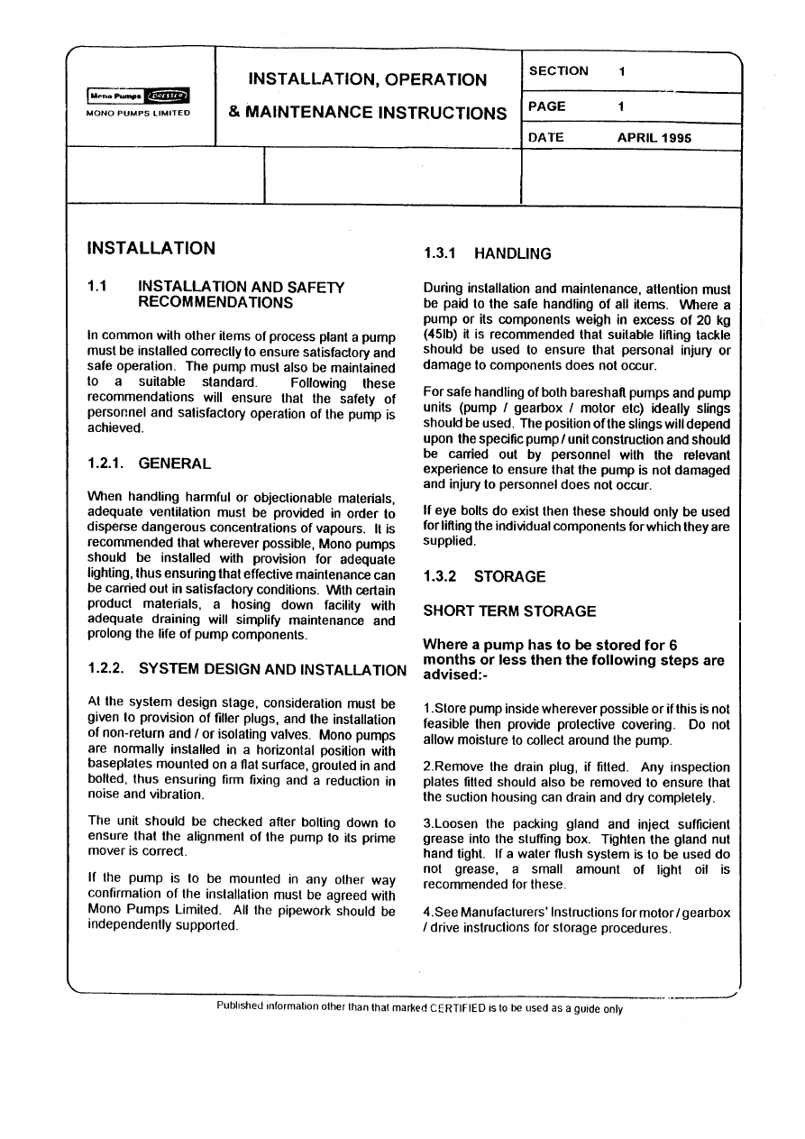
INSTALLATION
1.1
INSTALLATION AND SAFETY
RECOMMENDATIONS
In common with other items of process plant a pump
must be installed correctly to ensure satisfactory and
safe operation. The pump must also be maintained
to a suitable standard. Following these
recommendations will ensure that the safety of
personnel and satisfactory operation of the pump is
achieved.
1.2.1.
GENERAL
When handling harmful or objectionable materials,
adequate ventilation must be provided in order to
disperse dangerous concentrations of vapours. It is
recommended that wherever possible, Mono pumps
should be installed with provision for adequate
lighting, thus ensuring that effective maintenance
can be carried out in satisfactory conditions. With
certain product materials, a hosing down facility with
adequate draining will simplify maintenance and
prolong the life of pump components.
1.2.2.
SYSTEM DESIGN & INSTALLATION
At the system design stage, consideration must be
given to provision of filler plugs, and the installation
of non-return and/or isolating valves. Pumps cannot
be reliably used as non-return valves. Pumps in
parallel and those with high static discharge head
must be fitted with non-return valves.
The pumps must also be protected by suitable
devices against over pressure and dry running.
i.
HORIZONTAL MOUNTING
All ranges excluding P Range Mono pumps are
normally installed in a horizontal position with
baseplates mounted on a flat surface, grouted in
and bolted, thus ensuring firm fixing and a reduction
in noise and vibration.
The unit should be checked after bolting down to
ensure that the alignment of the pump to its prime
mover is correct.
ii.
VERTICAL MOUNTING
P Range Pumps Only
The P range pumps are intended for vertical
installation. Care must be taken when lifting the
pump into the vertical position.
Normally ‘P’ range pumps will be designed with a
sole plate that will be bolted to the customers
framework.
If the pump is to be mounted in any way other than
described above, confirmation of the installation
must be agreed with Mono Pumps Limited. All the
pipework should be independently supported.
1.3.1 HANDLING
During installation and maintenance, attention must
be paid to the safe handling of all items. Where a
pump or its components weigh in excess of 20 kg
(45lb) it is recommended that suitable lifting tackle
should be used to ensure that personal injury or
damage to components does not occur.
For safe handling of both bareshaft pumps and
pump units (pump/ gearbox/motor etc.) slings should
be used. The position of the slings will depend upon
the specific pump/unit construction and should be
carried out by personnel with the relevant
experience to ensure that the pump is not damaged
and injury to personnel does not occur.
If eyebolts do exist then these should only be used
for lifting the individual components for which they
are supplied.
1.3.2
STORAGE AND INFREQUENT OPERATION
The situation where a pump is used infrequently is
also covered by the instructions in this section.
SHORT TERM STORAGE
Where a pump has to be stored for 6 months or
less then the following steps are advised:-
1.
Store pump inside wherever possible or if this is not
feasible then provide protective covering. Do not
allow moisture to collect around the pump.
2.
Remove the drain plug, if fitted. Any inspection
plates fitted should also be removed to ensure that
the suction housing can drain and dry completely.
3.
Loosen the packed gland and inject sufficient grease
into the stuffing box. Tighten the gland nut hand
tight. If a water flush system is to be used do not
grease, a small amount of light oil is recommended
for these.
4.
See Manufacturers Instructions for
motor/gearbox/drive instructions for storage
procedures.
Installation, Operation & Maintenance Instructions
Section 1, Page 2
Issued - December 2002
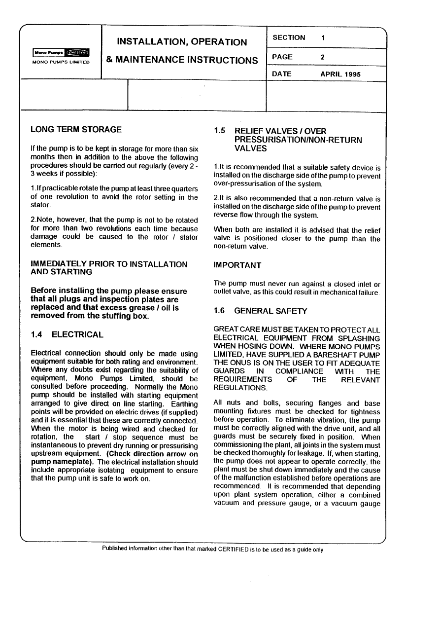
LONG TERM STORAGE
If the pump is to be kept in storage for more than
six months then in addition to the above the
following procedures should be carried out
regularly (every 2 - 3 weeks if possible):
1.
If practicable rotate the pump at least three quarters
of one revolution to avoid the rotor setting in the
stator.
2.
Note, however, that the pump is not to be rotated for
more than two revolutions each time because
damage could be caused to the rotor/ stator
elements.
IMMEDIATELY PRIOR TO INSTALLATION AND
STARTING
Before installing the pump please ensure that all
plugs and inspection plates are replaced and
that excess grease/oil is removed from the
stuffing box.
1.4 ELECTRICAL
Electrical connection should only be made using
equipment suitable for both rating and environment.
Where any doubts exist regarding the suitability of
equipment, Mono Pumps Limited, should be
consulted before proceeding. Normally the Mono
pump should be installed with starting equipment
arranged to give direct on line starting.
Earthing points will be provided on electric drives (if
supplied) and it is essential that these are correctly
connected. When the motor is being wired and
checked for rotation, the start/stop sequence must
be instantaneous to prevent dry running (see 2) or
pressurising upstream equipment. (Check direction
arrow on pump nameplate). The electrical
installation should include appropriate isolating
equipment to ensure that the pump unit is safe to
work on.
1.5
PRESSURE RELIEF VALVES AND NON-RETURN
VALVES
1.
It is recommended that a suitable safety device is
installed on the discharge side of the pump to
prevent over-pressurisation of the system.
2.
It is also recommended that a non-return valve is
installed on the discharge side of the pump to
prevent reverse flow through the system.
When both are installed it is advised that the relief
valve is positioned closer to the pump than the non-
return valve.
IMPORTANT
The pump must never run against a closed inlet
or outlet valve, as this could result in
mechanical failure.
1.6
GENERAL SAFETY
GREAT CARE MUST BE TAKEN TO PROTECT
ALL ELECTRICAL EQUIPMENT FROM
SPLASHING WHEN HOSING DOWN. WHERE
MONO PUMPS LIMITED HAVE SUPPLIED A
BARESHAFT PUMP THE ONUS IS ON THE USER
TO FIT ADEQUATE GUARDS IN COMPLIANCE
WITH THE REQUIREMENTS OF THE RELEVANT
REGULATIONS.
All nuts and bolts, securing flanges and base
mounting fixtures must be checked for tightness
before operation. To eliminate vibration, the pump
must be correctly aligned with the drive unit, and all
guards must be securely fixed in position. When
commissioning the plant, all joints in the system
must be checked thoroughly for leakage.
If, when starting, the pump does not appear to
operate correctly (see 2), the plant must be shut
down immediately and the cause of the malfunction
established before operations are recommenced. It
is recommended that depending upon plant system
operation, either a combined vacuum and pressure
gauge, or a vacuum gauge only be fitted to the
pump inlet port, and a pressure gauge fitted to the
outlet port, these will then continuously monitor the
pump operating conditions.
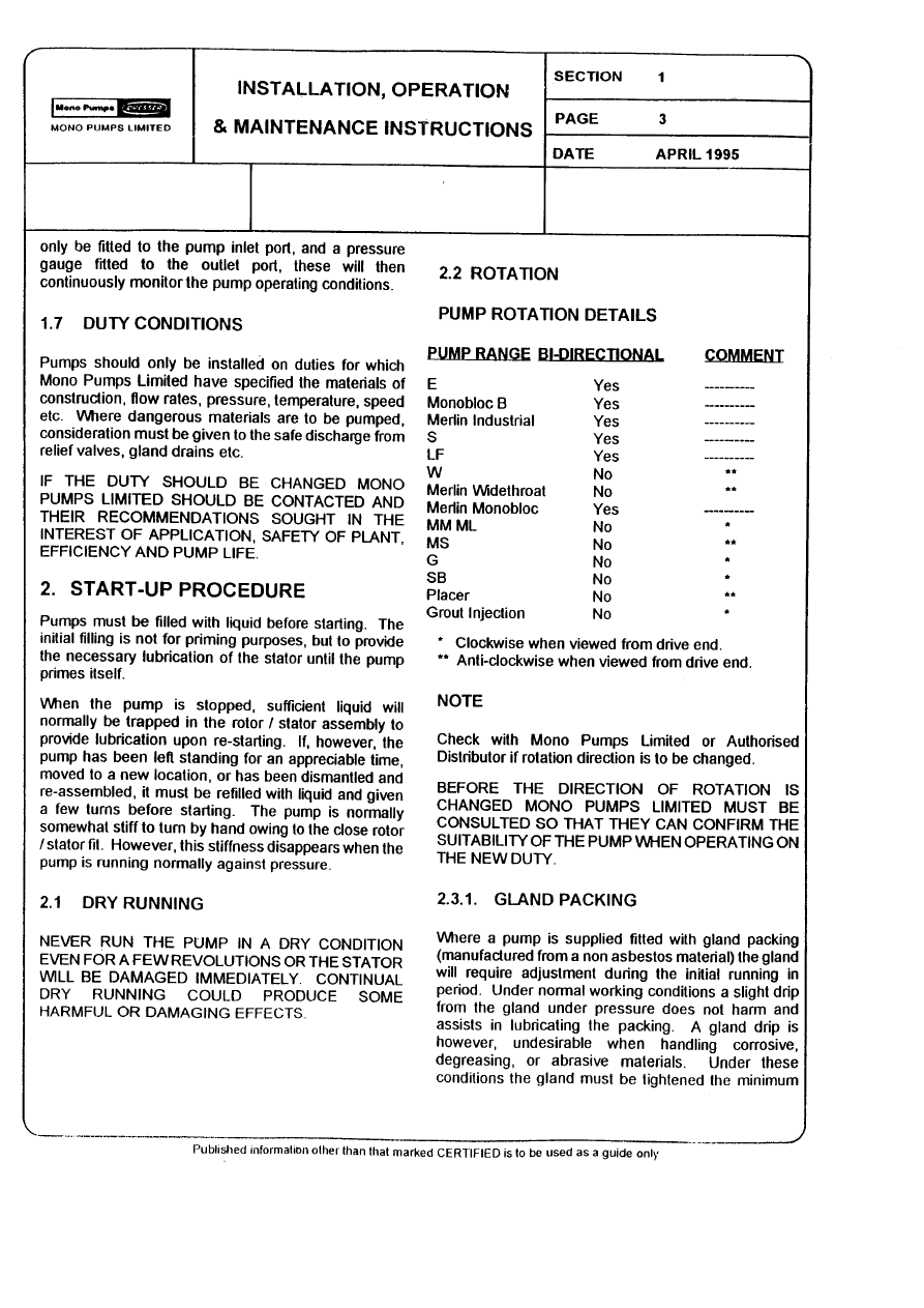
1.7
DUTY CONDITIONS
Pumps should only be installed on duties for which
Mono Pumps Limited have specified the materials of
construction, flow rates, pressure, temperature,
speed etc. Where dangerous materials are to be
pumped, consideration must be given to the safe
discharge from relief valves, gland drains etc.
IF THE DUTY SHOULD BE CHANGED, MONO
PUMPS LIMITED SHOULD BE CONTACTED AND
THEIR RECOMMENDATIONS SOUGHT IN THE
INTEREST OF APPLICATION, SAFETY OF
PLANT, EFFICIENCY AND PUMP LIFE.
Installation, Operation & Maintenance Instructions
Section 1, Page 3
Issued - December 2002
2.
START-UP PROCEDURE
Pumps must be filled with liquid before starting. The
initial filling is not for priming purposes, but to
provide the necessary lubrication of the stator until
the pump primes itself. When the pump is stopped,
sufficient liquid will normally be trapped in the
rotor/stator assembly to provide lubrication upon re-
starting.
If, however, the pump has been left standing for an
appreciable time, moved to a new location, or has
been dismantled and re-assembled, it must be
refilled with liquid and given a few turns before
starting. The pump is normally somewhat stiff to
turn by hand owing to the close rotor/stator fit.
However, this stiffness disappears when the pump is
running normally against pressure.
2.1
DRY RUNNING
NEVER RUN THE PUMP IN A DRY CONDITION
EVEN FOR A FEW REVOLUTIONS OR THE
STATOR WILL BE DAMAGED IMMEDIATELY.
CONTINUAL DRY RUNNING COULD PRODUCE
SOME HARMFUL OR DAMAGING EFFECTS.
2.2
PUMP ROTATION DETAILS
PUMP RANGE
BI-DIRECTIONAL
COMMENT
E
Yes
†
Monobloc B
Yes
†
Merlin Industrial
Yes
†
S, SL
Yes
†
LF
Yes
†
W
No
**
Merlin Widethroat
No
**
MM ML
No
*
MS
No
**
G
No
*
CB/SB
No
*
Placer
No
**
Grout Injection
No
**
P
No *
CP0011
No
**
CP0025,CP0800,CP1600
No
*
*
Clockwise when viewed from drive end.
**
Anti-clockwise when viewed from drive end.
†
Anti-clockwise gives inlet at drive end.
DIRECTIONS OF ROTATION
BEFORE THE DIRECTION OF ROTATION IS
CHANGED, MONO PUMPS LIMITED MUST BE
CONSULTED SO THAT THE SUITABILITY OF
THE PUMP CAN BE CONFIRMED WHEN
OPERATING ON THE NEW DUTY.
2.3.1.
GLAND PACKING
Where a pump is supplied fitted with gland packing
(manufactured from a non-asbestos material), the
gland will require adjustment during the initial
running in period. Newly packed glands must be
allowed to ‘run-in’ with only finger tight compression
on the gland follower nuts. This should continue for
about 3 days. The gland follower should be
gradually tightened over the next week to achieve a
leakage rate as shown in the table below. Gland
followers should be adjusted at regular intervals to
maintain the recommended leakage flow rate.
Under normal working conditions a slight drip from
the gland under pressure assists in cooling and
lubricating the packing. A correctly adjusted
gland will always have small leakage of fluid.
Typical Leakage Rates from Packed Glands
Up to 50mm shaft diameter
2 drops per minute
50 – 75mm shaft diameter
3 drops per minute
75 – 100mm shaft diameter
4 drops per minute
100 – 125mm shaft diameter
5 drops per minute
125 – 160mm shaft diameter
6 drops per minute
A gland drip is, however, undesirable when handling
corrosive, degreasing, or abrasive materials. Under
these conditions the gland must be tightened the
minimum amount whilst the pump is running to
ensure satisfactory sealing when under pressure, or
to stop entry of air when under suction conditions.
The gland leakage of toxic, corrosive or hazardous
liquids can cause problems of compatibility with the
pumps materials of construction.
Provision of a gland drain should be considered,
especially for the leakage of hazardous products.
CARE IS REQUIRED WHEN ADJUSTING THE
GLAND WHILST PUMP IS RUNNING.
2.3.2
MECHANICAL SEALS - ALL PUMPS
When a mechanical seal is fitted to the pump it may
be necessary to provide a barrier fluid to some part
of the seal. This should be provided in line with the
seal manufacturers instructions.
2.4.
GUARDS
In the interests of safety, and in accordance with the
U.K. Health and Safety at Work Act 1974, all guards
must be replaced after necessary adjustments have
been made to the pump.

Installation, Operation & Maintenance Instructions
Section 1, Page 4
Issued - December 2002
2.5
WARNING/CONTROL DEVICE
Prior to operating the pump, if any warning or control
devices are fitted these must be set in accordance
with their specific instructions.
2.6
PUMP OPERATING TEMPERATURE
The range of temperatures the pump surfaces will
develop is dependent upon factors such as product
temperature and ambient temperature of the
installation. There may be instances where the
external pump surface can exceed 50oC.
In these instances, personnel must be made aware
of this and suitable warnings/guarding used.
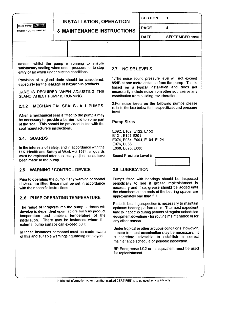
2.7
NOISE LEVELS
1.
The noise sound pressure level will not exceed
85dB at one metre distance from the pump.
2.
This is based on a typical installation and does not
necessarily include noise from other sources or any
contribution from building reverberation.
3.
For pumps identified below, the noise levels vary
between 85 and 95dB but will not exceed 95dB at
one metre distance from the pump.
Pump Sizes (based on E Range Pumping
Element)
Single Stage
Size 12 and above
Two Stage
Size 9 and above
Four Stage
Size 7 and above
Six Stage
Size 7 and above
Eight Stage
Size 6 and above
2.8
LUBRICATION
Pumps fitted with bearings should be inspected
periodically to see if grease replenishment is
necessary, and if so, grease should be added until
the chambers at the ends of the bearing spacer are
approximately one third full.
Periodic bearing inspection is necessary to maintain
optimum bearing performance. The most expedient
time to inspect is during periods of regular
scheduled equipment downtime - for routine
maintenance or for any other reason.
Under tropical or other arduous conditions, however,
a more frequent examination may be necessary. It
is therefore advisable to establish a correct
maintenance schedule or periodic inspection.
BP LC2 / Mobilgrease XHP 222 or their equivalent
must be used for replenishment.
2.9
PUMP UNITS
Where a pump unit is dismantled and re-assembled,
consideration must be given to ensure that where
appropriate the following steps are covered.
1.
Correct alignment of pump/gearbox
2.
Use of appropriate couplings & bushes
3.
Use of appropriate belts & pulleys correctly
tensioned.
2.10
CLEANING PRIOR TO OPERATION
i.
Non Food Use
During the commissioning of a new pump or
recommissioning of an overhauled pump, it is
advisable to clean the pump prior to the initial
operation of the pump in the process.
ii.
Food Use
When a pump has been supplied for a food
application, it is important to ensure that the pump is
clean prior to initial operation of the pump.
Therefore, it is important that a clean-in-place
treatment is executed on the pump at the following
times:-
1.
When the pump is first commissioned for use.
2.
When any spare components are fitted into the
wetted area of the pump.
A recommended CIP procedure is as follows:
This procedure should not be used on the CP
Pump Range. Please consult our application
engineers for a suitable procedure.
Caustic Wash
LQ94 ex Lever Diversey or equivalent
2% concentration
Acid Wash
P3 Horolith 617 ex Henkel
Ecolab or equivalent 1% concentration
Procedure
1. Caustic wash @ 75°C for 20 mins
2.
Water rinse @ 80°C for 20 mins
Installation, Operation & Maintenance Instructions
Section 1, Page 5
Issued - December 2002
3.
Acid wash @ 50°C for 20 mins
4.
Water rinse @ 80°C for 20 mins
•
CIP flow rates (hence pump speeds) should be
maximised to achieve highest level of cleanability.
A C.I.P. liquid velocity of 1.5 to 2.0 m/s is required
for removal of solids and soiling.
Pumps fitted with CIP by pass ports will permit
higher flow rates without the need to increase pump
speed.
•
The use of ‘neat active’ caustic
and acid chemicals is not
recommended. Proprietary cleaning
agents should be used in line with manufacturers
instructions.
•
All seals and gaskets should be
replaced with new if disturbed
during maintenance.
•
Pump internals should be regularly inspected to
ensure hygienic integrity is maintained, especially
with respect to elastomeric components and seals,
and replaced if necessary.
The four stages constitute one cycle and we
recommend that this cycle is used to clean the pump
before use on food.
Once the pump has been commissioned, the
cleaning process will depend upon the application.
The user must therefore ensure that their cleaning
procedures are suitable for the duty for which the
pump has been purchased.
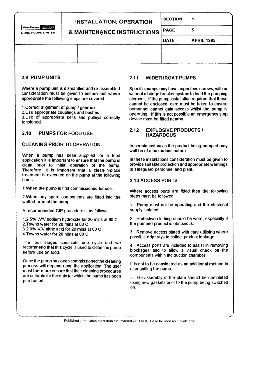
2.11
WIDETHROAT PUMPS
Specific pumps may have auger feed screws, with
or without a bridge breaker system to feed the
pumping element. If the pump installation requires
that these cannot be enclosed, care must be taken
to ensure personnel cannot gain access whilst the
pump is operating. If this is not possible an
emergency stop device must be fitted nearby.
2.12
EXPLOSIVE PRODUCTS/ HAZARDOUS
ATMOSPHERES
In certain instances the product being pumped may
well be of a hazardous nature.
In these installations consideration must be given to
provide suitable protection and appropriate warnings
to safeguard personnel and plant.
2.13 ACCESS
PORTS
Where access ports are fitted then the following
steps must be followed prior to removal:
1.
Pump must be shut down and the electrical supply
isolated.
2.
Protective clothing should be worn, especially if the
pumped product is obnoxious.
3.
Remove access plate with care utilising where
possible drip trays to collect product leakage.
Access ports are included to assist in removing
blockages and to allow a visual check on the
components within the suction chamber.
It is not to be considered as an additional method in
dismantling the pump.
Re-assembly of the plate should be completed using
new gaskets prior to the pump being switched on.
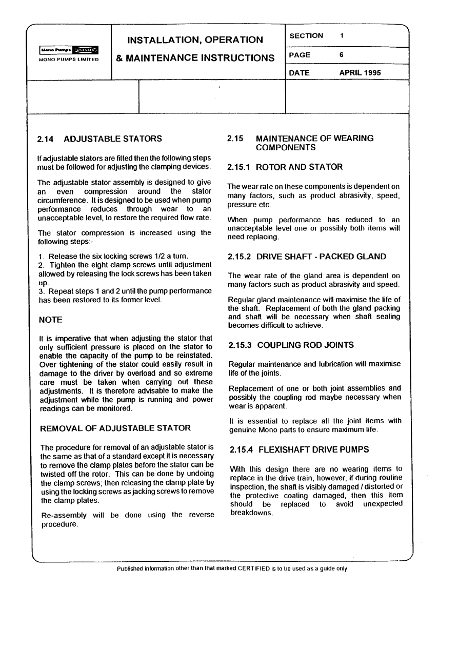
2.14
ADJUSTABLE STATORS
If adjustable stators are fitted then the following
steps must be followed for adjusting the clamping
devices.
The adjustable stator assembly is designed to give
an even compression around the stator
circumference. It is designed to be used when
pump performance reduces through wear to an
unacceptable level, to restore the required flow rate.
The stator compression is increased using the
following steps:-
1.
Release the six locking screws half a turn.
2.
Tighten the eight clamp screws until adjustment
allowed by releasing the lock screws has been taken
up.
3.
Repeat steps 1 and 2 until the pump performance
has been restored to its former level.
NOTE
It is imperative that when adjusting the stator that
only sufficient pressure is placed on the stator to
enable the capacity of the pump to be reinstated.
Over tightening of the stator could easily result in
damage to the driver by overload and so extreme
care must be taken when carrying out these
adjustments.

Installation, Operation & Maintenance Instructions
Section 1, Page 6
Issued - December 2002
It is therefore advisable to make the adjustment
while the pump is running and power readings can
be monitored.
REMOVAL OF ADJUSTABLE STATOR
The procedure for removal of an adjustable stator is
the same as that of a standard one, except it is
necessary to remove the clamp plates before the
stator can be twisted off the rotor.
This can be done by undoing the clamp screws;
then releasing the clamp plate by using the locking
screws as jacking screws to remove the clamp
plates.
Re-assembly will be done using the reverse
procedure.
2.15
MAINTENANCE OF WEARING COMPONENTS
2.15.1
ROTOR AND STATOR
The wear rate on these components is dependent
on many factors, such as product abrasivity, speed,
pressure etc.
When pump performance has reduced to an
unacceptable level one or possibly both items will
need replacing.
2.15.2
DRIVE SHAFT - PACKED GLAND
The wear rate of the gland area is dependent on
many factors such as product abrasivity and speed.
Regular gland maintenance will maximise the life of
the shaft. Replacement of both the gland packing
and shaft will be necessary when shaft sealing
becomes difficult to achieve.
2.15.3
COUPLING ROD JOINTS
Regular maintenance and lubrication will maximise
life of the joints.
Replacement of one or both joint assemblies and
possibly the coupling rod may be necessary when
wear is apparent.
It is essential to replace all the joint items with
genuine Mono parts to ensure maximum life.
2.15.4
FLEXISHAFT DRIVE PUMPS
With this design there are no wearing items to
replace in the drive train, however, if during routine
inspection the shaft is visibly damaged / distorted
or the protective coating is damaged, then this item
should be replaced to avoid unexpected
breakdowns.
2.16
MECHANICAL SPEED VARIATORS
Refer to the manufacturers instructions.
These machines require regular maintenance, which
typically includes weekly adjustment through the full
speed range.
3.0
ASSEMBLY AND DISMANTLING
Section 4 contains the steps to dismantle and
re-assemble the pump. All fastenings must be
tightened securely and when identified the
appropriate torque figures should be used.
3.1
USE OF ITEMS NOT APPROVED OR
MANUFACTURED BY MONO PUMPS LIMITED
The pump and its components have been designed
to ensure that the pump will operate safely within the
guidelines covered by the legislation.
As a consequence Mono Pumps Limited have
declared the machine safe to use for the duty
specified as defined by the Declaration of
Incorporation or Conformity that is issued with this
Instruction Manual.
The use of replacement items that are not approved
by or manufactured by Mono Pumps Limited may
affect the safe operation of the pump and it may
therefore become a safety hazard to both operators
and other equipment. In these instances the
Declaration provided will therefore become invalid.
The guarantee referenced in the Terms and
Conditions of Sale will also be invalidated if
replacement items are used that are not approved or
manufactured by Mono Pumps Limited.
DISPOSAL OF WORN COMPONENTS
When replacing wearing parts, please ensure
disposal of used parts is carried out in compliance
with local environmental legislation. Particular care
should be taken when disposing of lubricants.

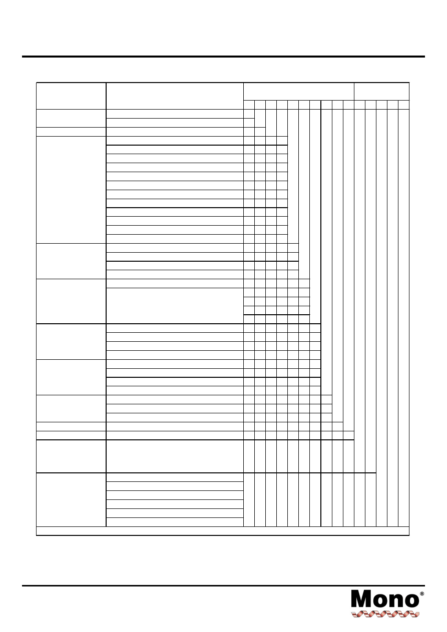
Diagnostic Chart
Section 2, Page 1
Issued - December 2000
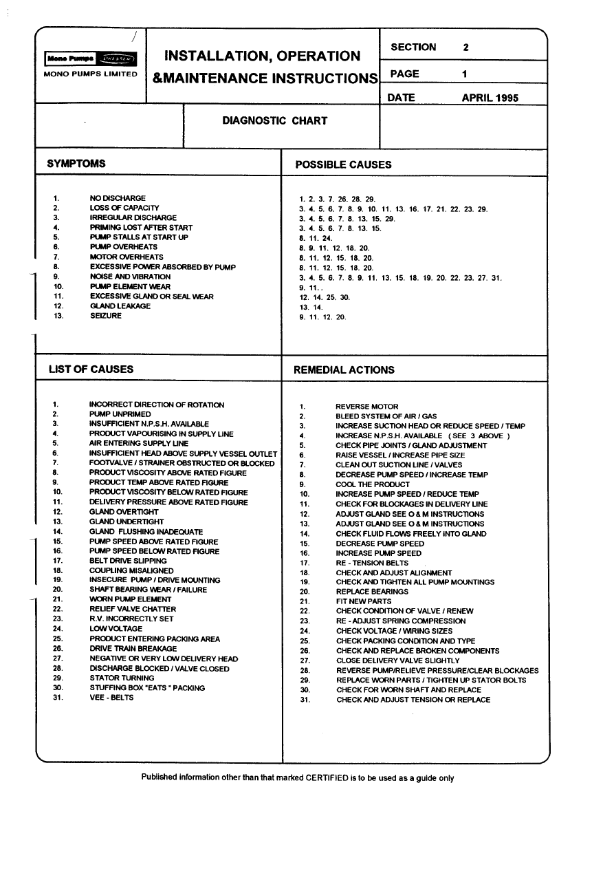
SYMPTOMS
POSSIBLE CAUSES
1.
NO DISCHARGE
2.
LOSS OF CAPACITY
3.
IRREGULAR DISCHARGE
4.
PRIMING LOST AFTER START
5.
PUMP STALLS AT START UP
6.
PUMP OVERHEATS
7.
MOTOR OVERHEATS
8.
EXCESSIVE POWER ABSORBED BY PUMP
9.
NOISE AND VIBRATION
10.
PUMP ELEMENT WEAR
11.
EXCESSIVE GLAND OR SEAL WEAR
12.
GLAND LEAKAGE
13.
SEIZURE
1. 2. 3. 7. 26. 28. 29.
3. 4. 5. 6. 7. 8. 9. 10. 22. 13. 16. 17. 21. 22. 23. 29
3. 4. 5. 6. 7. 8. 13. 15. 29.
3. 4. 5. 6. 7. 8. 13. 15
8. 11. 24.
8. 9. 11. 12. 18. 20
8. 11. 12. 15. 18. 20.
8. 11. 12. 15. 18. 20
3. 4. 5. 6. 7. 8. 9. 11. 13. 15. 18. 19. 20. 22. 23. 27. 31
9. 11.
12. 14. 25. 30.
13. 14.
9. 11. 12. 20.
LIST OF CAUSES
REMEDIAL ACTIONS
1.
INCORRECT DIRECTION OF ROTATION
2.
PUMP UNPRIMED
3.
INSUFFICIENT N.P.S.H. AVAILABLE
4.
PRODUCT VAPORISING IN SUPPLY LINE
5.
AIR ENTERING SUPPLY LINE
6.
INSUFFICIENT HEAD ABOVE SUPPLY VESSEL OUTLET
7.
FOOTVALVE/STRAINER OBSTRUCTED OR BLOCKED
8.
PRODUCT VISCOSITY ABOVE RATED FIGURE
9.
PRODUCT TEMP. ABOVE RATED FIGURE
10.
PRODUCT VISCOSITY BELOW RATED FIGURE
11.
DELIVERY PRESSURE ABOVE RATED FIGURE
12.
GLAND OVERTIGHT
13.
GLAND UNDERTIGHT
14.
GLAND FLUSHING INADEQUATE
15.
PUMP SPEED ABOVE RATED FIGURE
16.
PUMP SPEED BELOW RATED FIGURE
17.
BELT DRIVE SLIPPING
18.
COUPLING MISALIGNED
19.
INSECURE PUMP/DRIVE MOUNTING
20.
SHAFT BEARING WEAR/FAILURE
21.
WORN PUMP ELEMENT
22.
RELIEF VALVE CHATTER
23.
R.V. INCORRECTLY SET
24.
LOW VOLTAGE
25.
PRODUCT ENTERING PACKING AREA
26.
DRIVE TRAIN BREAKAGE
27.
NEGATIVE OR VERY LOW DELIVERY HEAD
28.
DISCHARGE BLOCKED/VALVE CLOSED
29.
STATOR TURNING
30.
STUFFING BOX “EATS” PACKING
31.
VEE BELTS
1.
REVERSE MOTOR
2.
BLEED SYSTEM OF AIR/GAS
3.
INCREASE SUCTION HEAD OR REDUCE SPEED/TEMP.
4.
INCREASE N.P.S.H. AVAILABLE (SEE 3 ABOVE)
5.
CHECK PIPE JOINTS/GLAND ADJUSTMENT
6.
RAISE VESSEL/INCREASE PIPE SIZE
7.
CLEAN OUT SUCTION LINE/VALVES
8.
DECREASE PUMP SPEED/INCREASE TEMP.
9.
COOL THE PRODUCT
10.
INCREASE PUMP SPEED/REDUCE TEMP.
11.
CHECK FOR BLOCKAGES IN DELIVERY LINE
12.
ADJUST GLAND SEE O&M INSTRUCTIONS
13.
ADJUST GLAND SEE O&M INSTRUCTIONS
14.
CHECK FLUID FLOWS FREELY INTO GLAND
15.
DECREASE PUMP SPEED
16.
INCREASE PUMP SPEED
17.
RE-TENSION BELTS
18.
CHECK AND ADJUST ALIGNMENT
19.
CHECK AND TIGHTEN ALL PUMP MOUNTINGS
20.
REPLACE BEARINGS
21.
FIT NEW PARTS
22.
CHECK CONDITION OF VALVE/RENEW
23.
RE-ADJUST SPRING COMPRESSION
24.
CHECK VOLTAGE/WIRING SIZES
25.
CHECK PACKING CONDITION AND TYPE
26.
CHECK AND REPLACE BROKEN COMPONENTS
27.
CLOSE DELIVERY VALVE SLIGHTLY
28.
REVERSE PUMP/RELIEVE PRESSURE/CLEAR BLOCKAGES
29.
REPLACE WORN PARTS/TIGHTEN UP STATOR BOLTS
30.
CHECK FOR WORN SHAFT AND REPLACE
31.
CHECK AND ADJUST TENSION OR REPLACE

Drawing Reference Numbers
Section 3, Page 1
Issued - April 2002
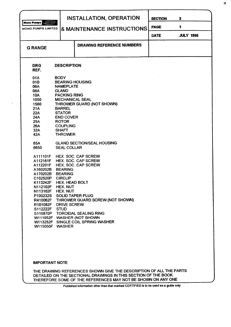
DRG.
REF
DESCRIPTION
DRG.
REF
DESCRIPTION
01A
01B
06A
06B
08A
10A
10B
15A
20A
20B
20C
22A
23A
23B
24A
25A
26A
32A
42A
47A
47B
62A
62B
65A
66A
75A
76A
95A
P101
P102
P103
P104
P105
P106
P107
P108
P109
P201
P202
P203
BODY
BODY ADAPTOR
NAMEPLATE (SOG)
NAMEPLATE (DOG)
GLAND FOLLOWER
GLAND PACKING/MECHANICAL SEAL
ROTARY SHAFT LIPSEAL (OPTIONAL)
THROWER GUARD
GASKET - GLAND
GASKET - STATOR SUPPORT RING
GASKET - STATOR SUPPORT RING
STATOR
SUCTION CHAMBER
SUCTION CHAMBER EXTENSION
END COVER
ROTOR
FLEXISHAFT
SHAFT
THROWER
STATOR SUPPORT RING
STATOR SUPPORT RING
SUPPORT FOOT
SUPPORT FOOT
GLAND SECTION
ABUTMENT RING
SLEEVE ROTOR
ADAPTOR FLANGE
TIE ROD
HEX HD SCREW
PLAIN WASHER
RD HD DRIVE SCREW
HEX HD BOLT
HEX NUT
PLAIN WASHER
SPRING WASHER
SPRING WASHER
HEX NUT
HEX HD BOLT
HEX NUT
PLAIN WASHER
P401
P402
P403
P404
P405
P406
P407
P408
P501
P502
P503
P504
P505
P506
P507
P508
P509
P510
P511
P512
P513
P514
P515
PIN
SEAL
SEAL
SEAL
CAP SCREW
PLAIN WASHER
SPIRAL RET. RING
PIN
PLUG
PLUG
PLUG
HEXAGON NUT
SPRING WASHER
PLAIN WASHER
HEXAGON NUT
SPRING WASHER
PLAIN WASHER
HEXAGON HEAD BOLT
HEXAGON NUT
SPRING WASHER
PLAIN WASHER
SEAL
SEAL
IMPORTANT NOTE
THE DRAWING REFERENCES SHOWN GIVE THE DESCRIPTION OF ALL THE PARTS DETAILED ON THE SECTIONAL
DRAWINGS IN THIS SECTION OF THE BOOK. THEREFORE SOME OF THE REFERENCES MAY NOT BE SHOWN ON
ANY ONE.
Pump Coding
Section 3, Page 2
Issued - November 2004
1
2
3
4
5
6
7
8
9
10
/
12 13 14 15
Cast Iron
C
Stainless Steel
S
PUMP DESIGN
Monobloc
B
1.3m³/h @ 1750 rev/min
0
1
3.3m³/h @ 1750 rev/min
0
2
10m³/h @ 1500 rev/min
0
3
13m³/h @ 1500 rev/min
0
X
22m³/h @ 1000 rev/min
0
4
37m³/h @ 800 rev/min
0
5
57m³/h @ 700 rev/min
0
6
79m³/h @ 600 rev/min
0
7
97m³/h @ 500 rev/min
0
8
125m³/h @ 450 rev/min
0
9
165m³/h @ 400 rev/min
1
0
225m³/h @ 350 rev/min
1
2
Low Pressure
K
One
1
Two
2
Four
4
Bareshaft (Size 041 & above)
H
A
B
C
D
Str.thro E/C, Mk 1 rotor
E
90º E/C, Mk 1 rotor
F
Str.thro E/C, Mk 0 rotor
K
90º E/C, Mk 0 rotor
M
Str.thro E/C, Mk 1 rotor
C
90º E/C, Mk 1 rotor
G
Str.thro E/C, Mk 0 rotor
X
90º E/C, Mk 0 rotor
Y
1
2
B-Range Square Inlet
S
STATOR MAT'L
RA, RR etc.
A
ROTATING PARTS
1, 3, 4, 5, 8
3
TYPICAL BASIC
PUMP CODING
Cast Iron Monobloc size 05 single stage.
Mechanical seal, str thro E/C, Std duty
conditions, Mk 0 rotor, Design 1, Natural rubber
stator, Code 3 rotating parts
C
B
0
5
1
B
K
1
A
3
'G' - Standard Bloc
'H' - Standard Bareshaft
'C' - Bareshaft - Mono Australia Only
'A' - ANSI + Access Ports
'E' - Standard ANSI
'J' - Japan
DESCRIPTION
BASIC PUMP CODE
STANDARD
VARIATION
BUILD OPTIONS
Refer to Mono Pumps Limited
BODY MATERIALS
NOMINAL PUMP
CAPACITY AT
MAXIMUM SPEED
AND ZERO
PRESSURE
PUMP STAGES
FEATURES
MECHANICAL SEAL
END COVER & DUTY
CONDITIONS
PACKED GLAND
END COVER,
STATOR DESIGN &
DUTY CONDITIONS
DESIGN MARK
NUMBER
3
/
G
5
1
PRIME MOVER AND
PORT OPTIONS
C
FULL PUMP CODING TO BE STAMPED ON PUMP NAMEPLATE
B
K
1
A
B
0
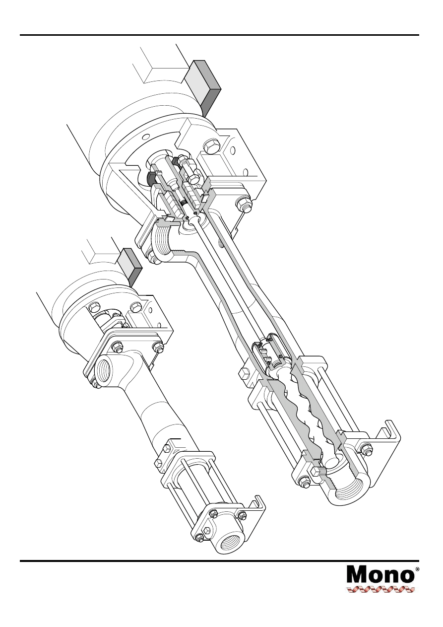
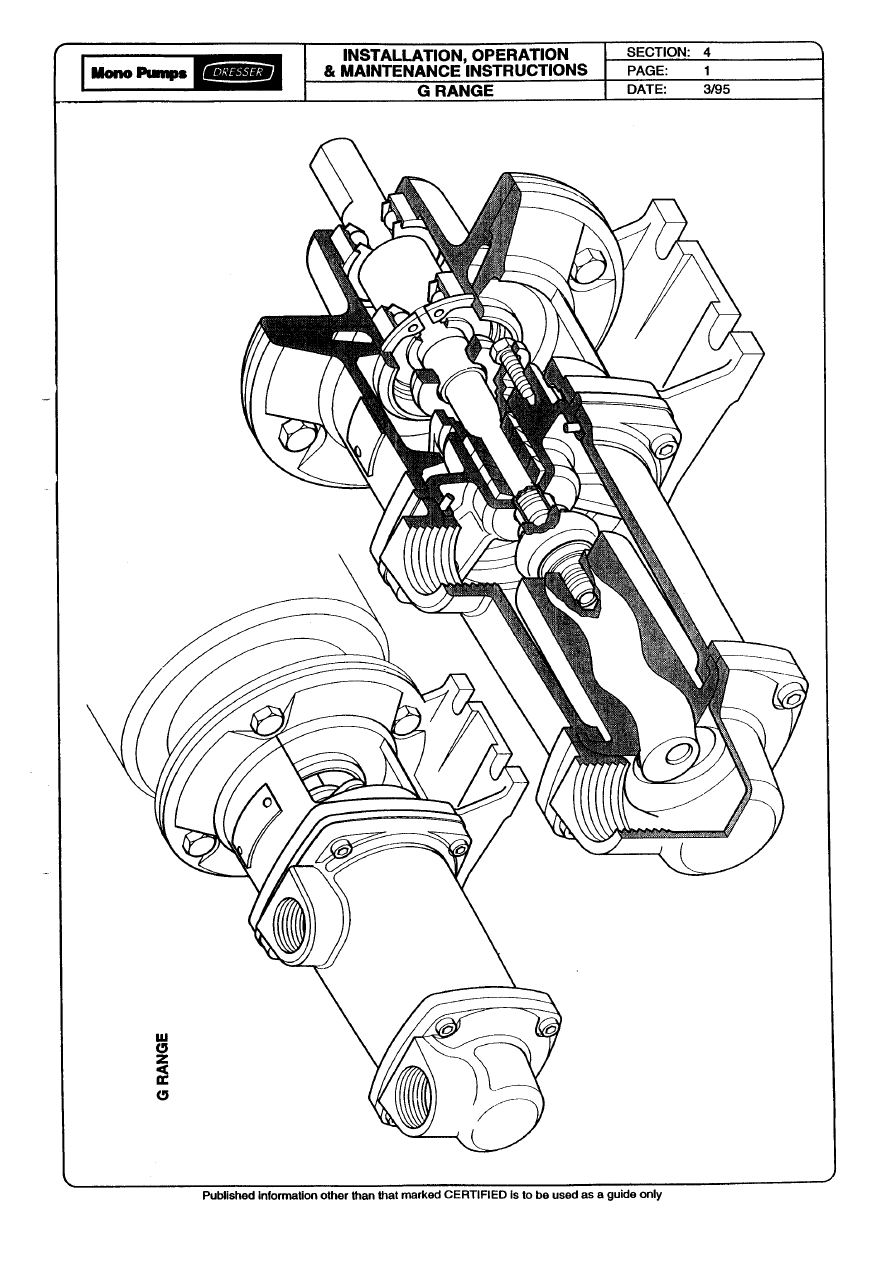
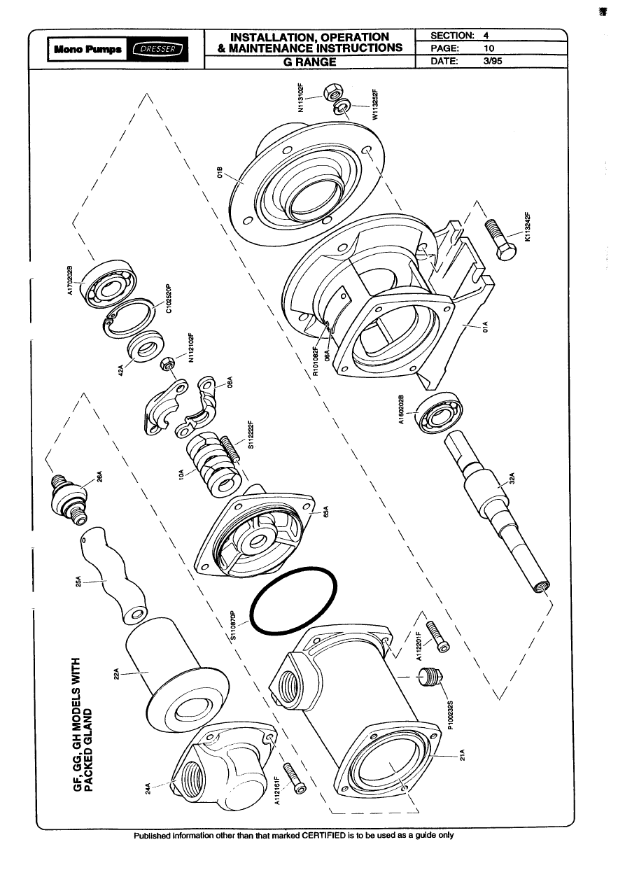
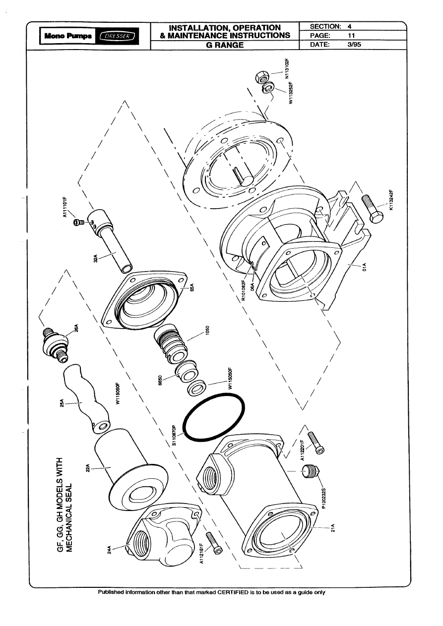
Dismantling & Assembly Diagrams
Section 4, Page 1
Issued - April 2004
B
RANGE
Flexishaft
Pump
Dismantling & Assembly Diagrams
Section 4, Page 2
Issued - August 2001
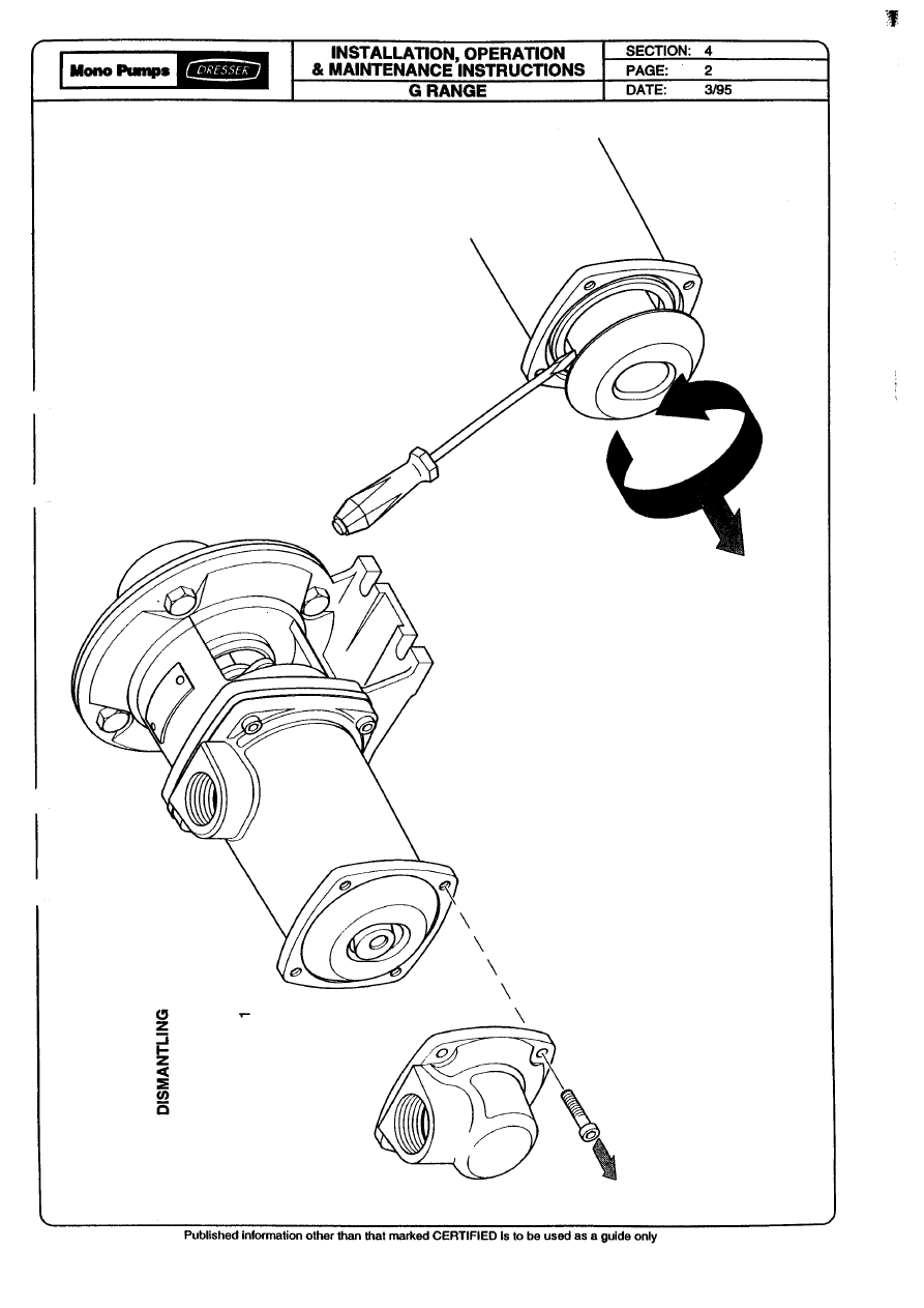
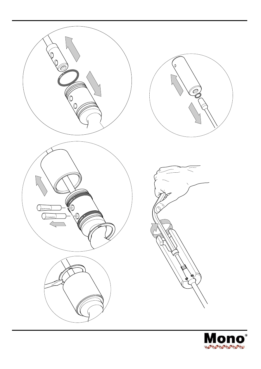
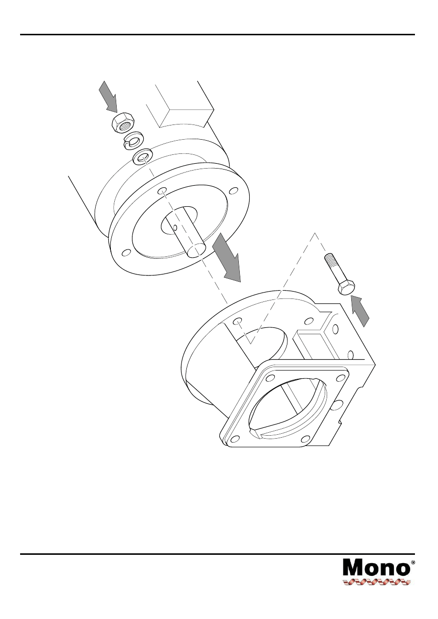
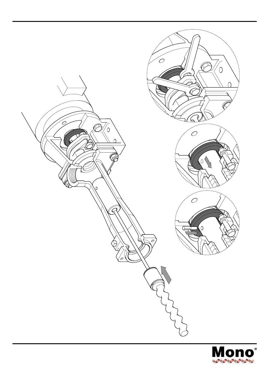
DISMANTLING
PROCEDURE
1
ALTERNATIVE
ROTOR
SUPPORT
-
SLING
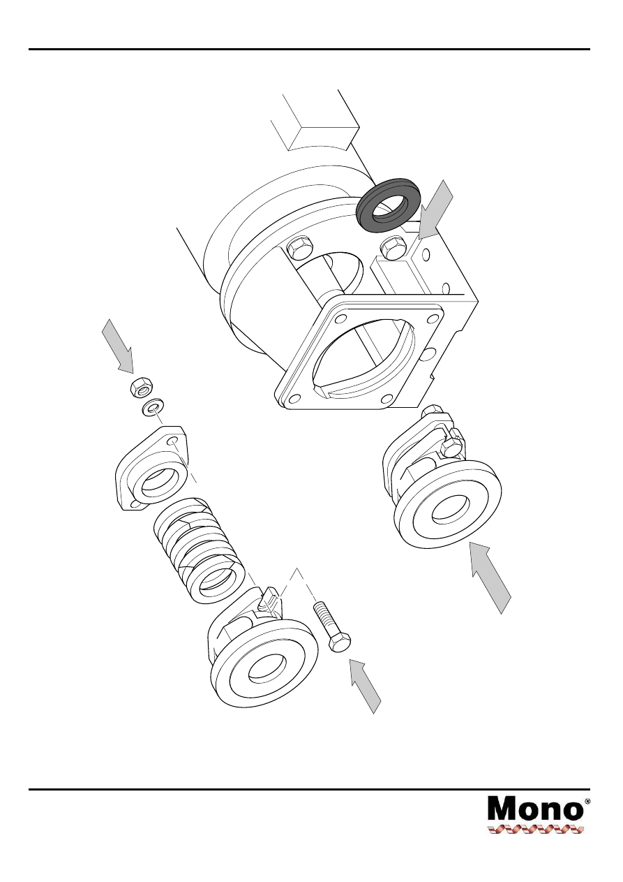
2
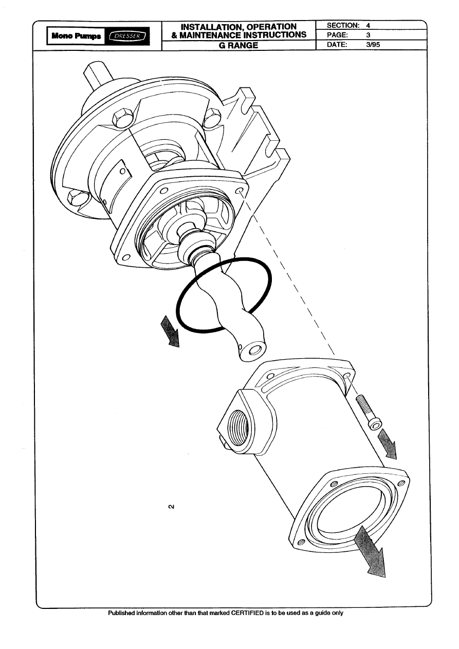
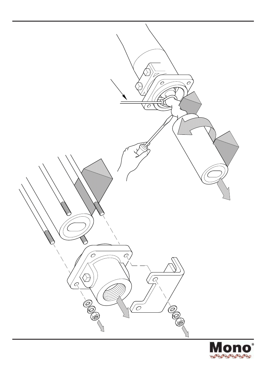
Dismantling & Assembly Diagrams
Section 4, Page 3
Issued - December 2000
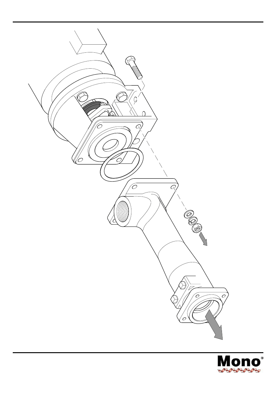
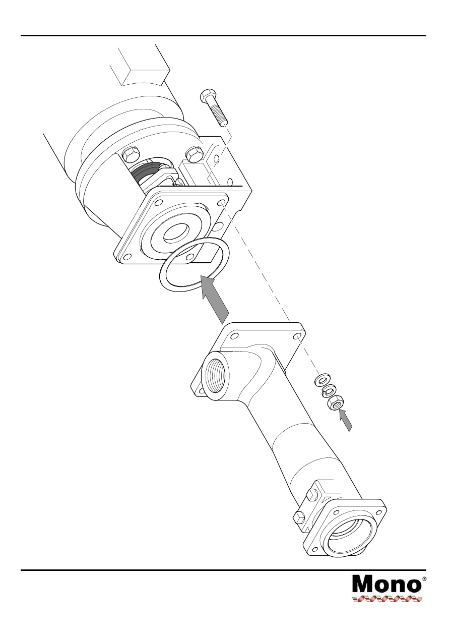
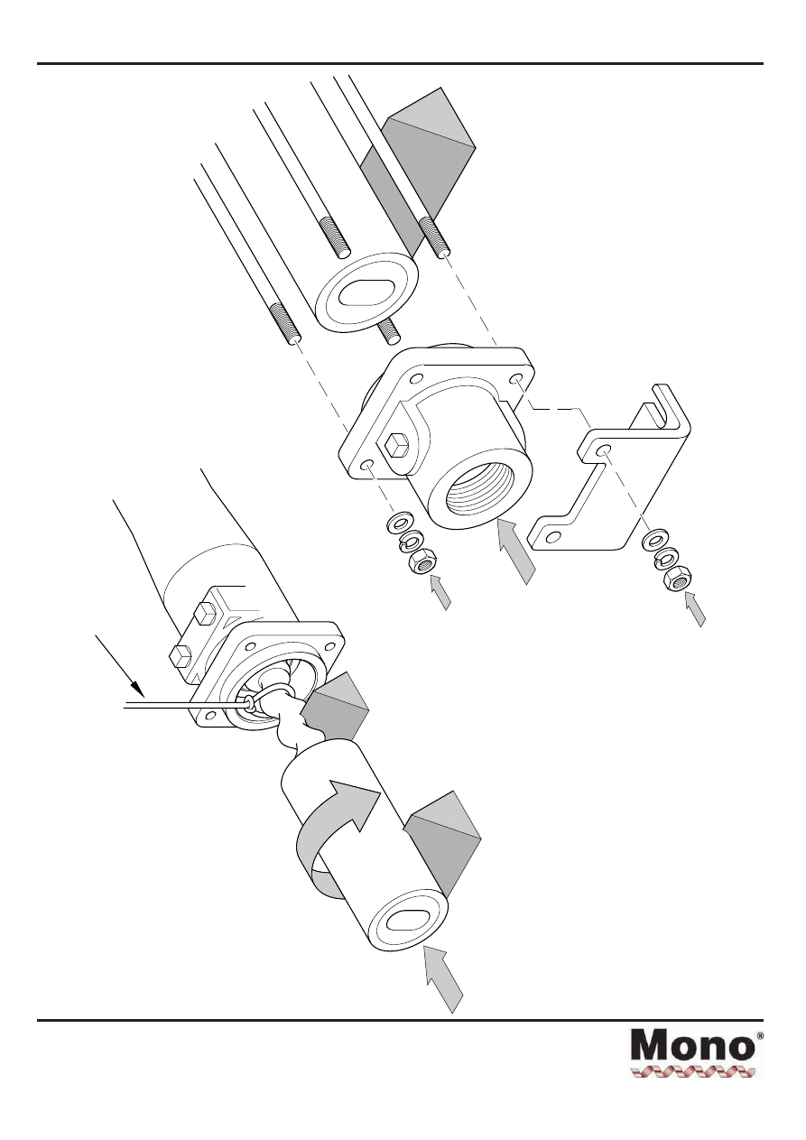
3
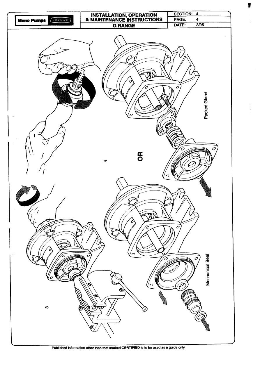
Dismantling & Assembly Diagrams
Section 4, Page 4
Issued - December 2000
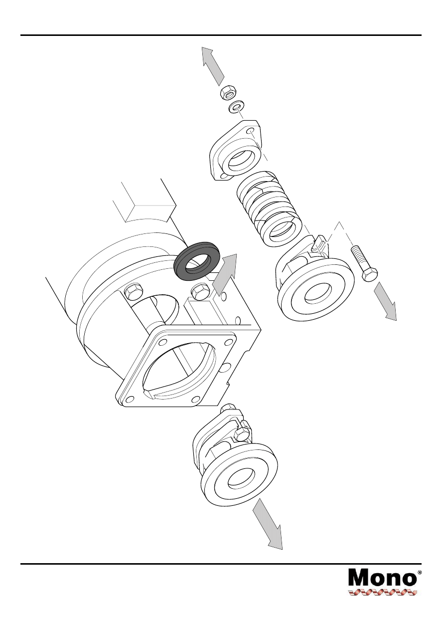
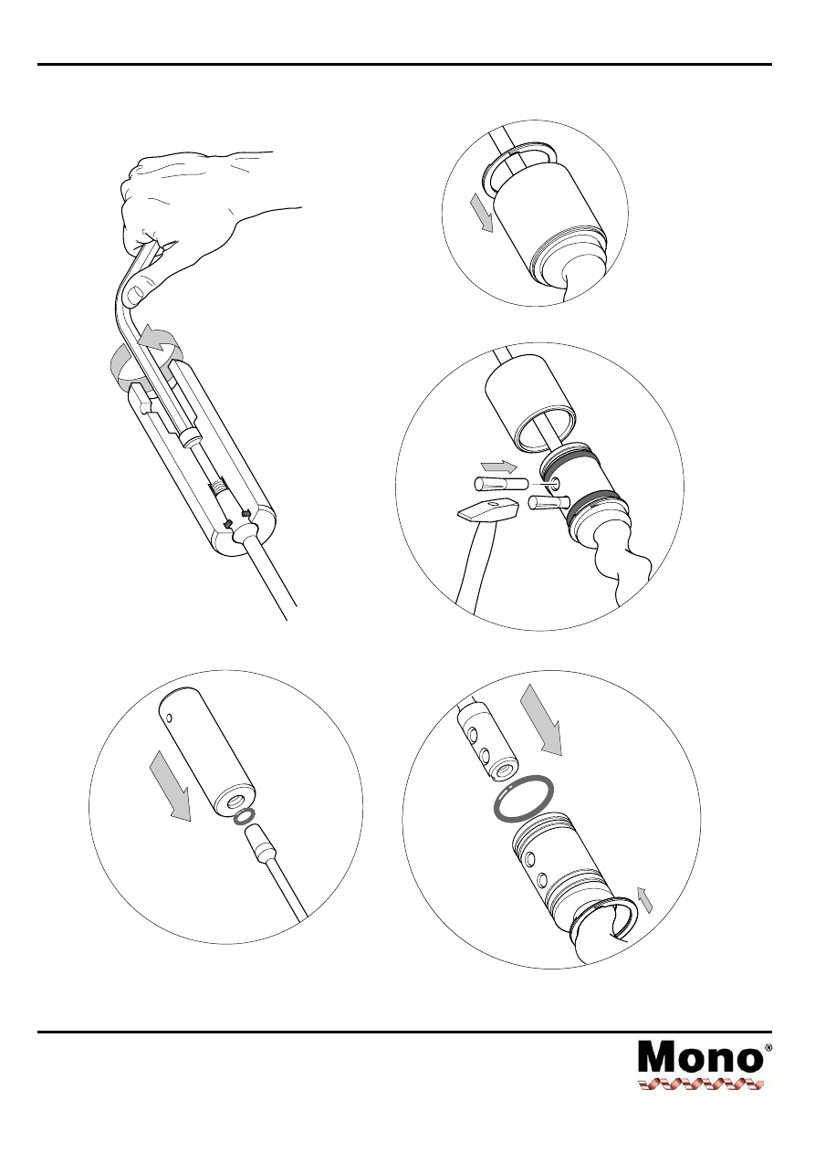
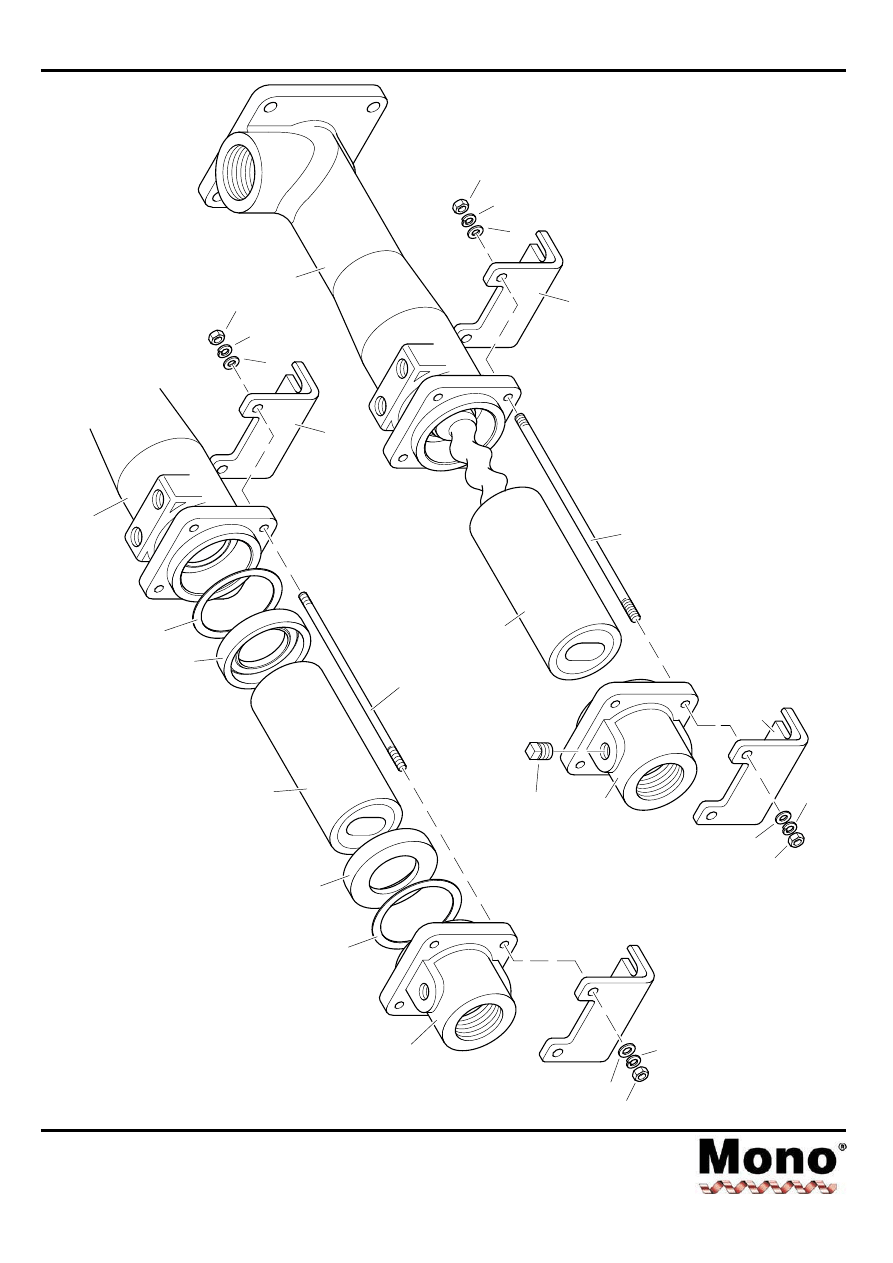
4
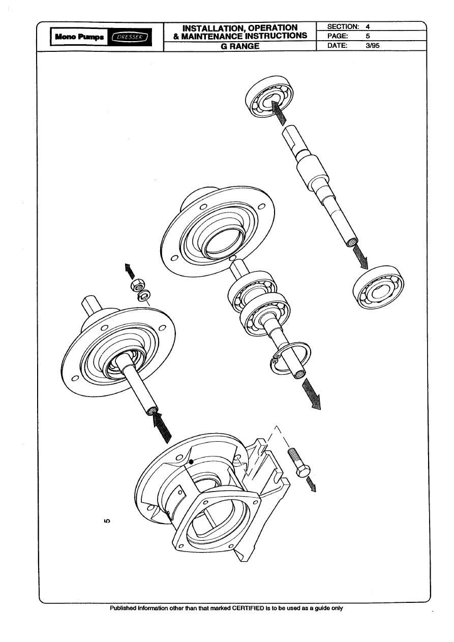
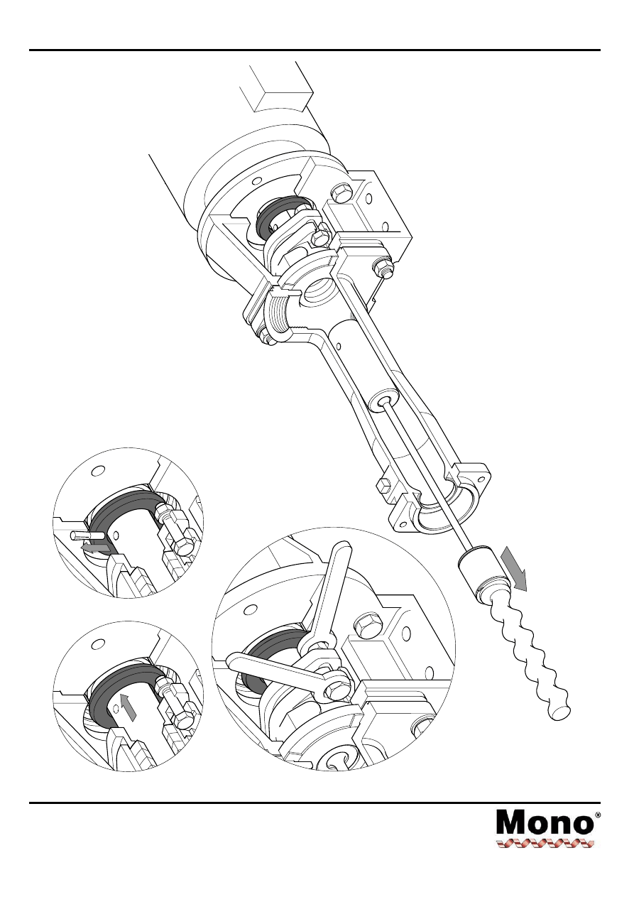
Dismantling & Assembly Diagrams
Section 4, Page 5
Issued - December 2000
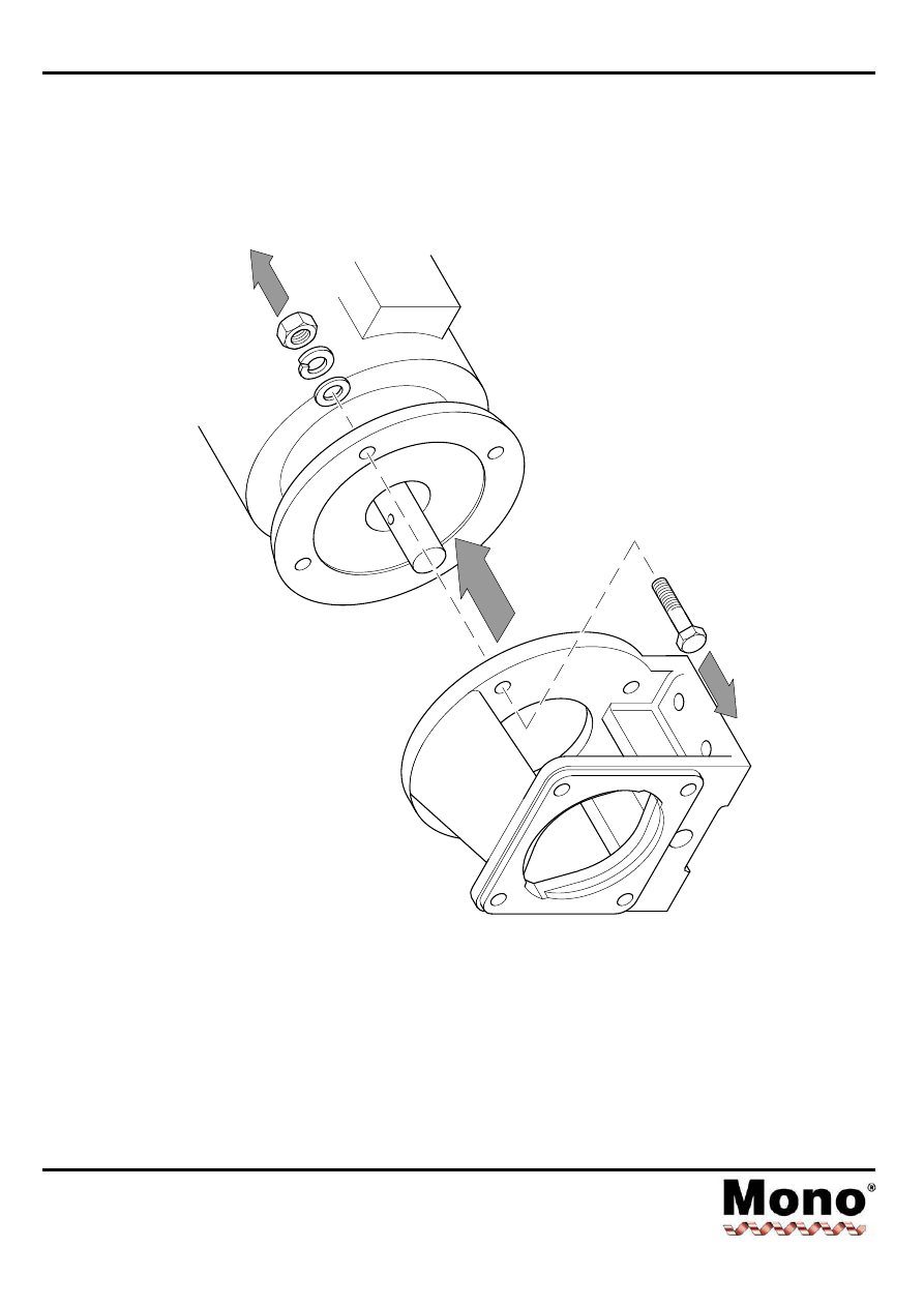
5
Dismantling & Assembly Diagrams
Section 4, Page 6
Issued - December 2000
6
Dismantling & Assembly Diagrams
Section 4, Page 7
Issued - December 2000
7
Dismantling & Assembly Diagrams
Section 4, Page 8
Issued - December 2000
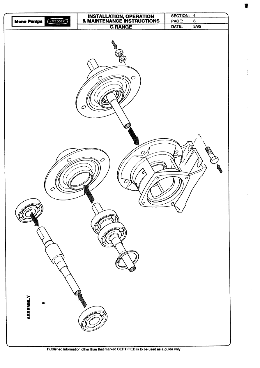
8
ASSEMBLY
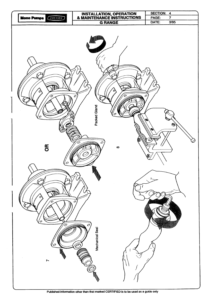
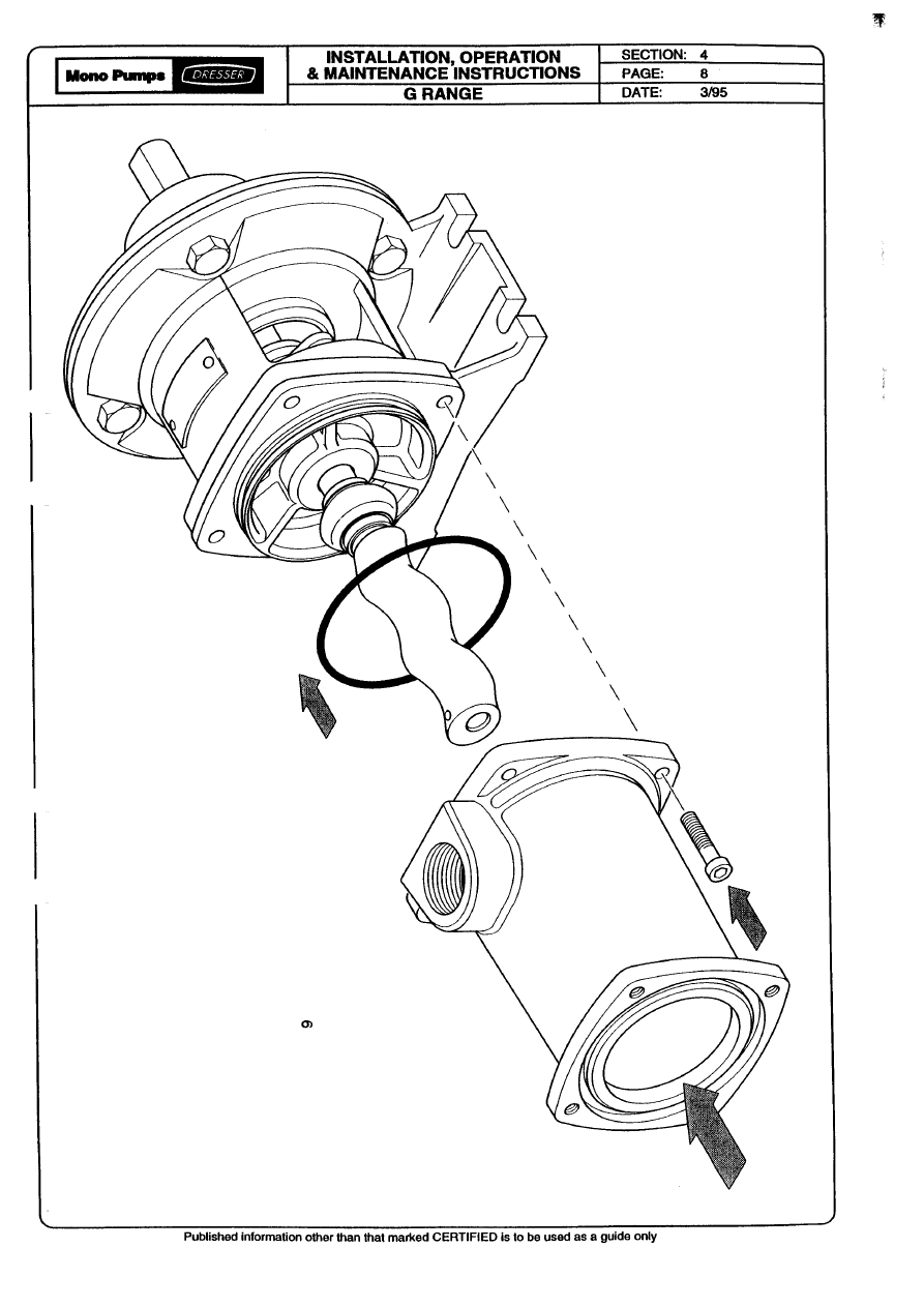
Dismantling & Assembly Diagrams
Section 4, Page 9
Issued - December 2000
9
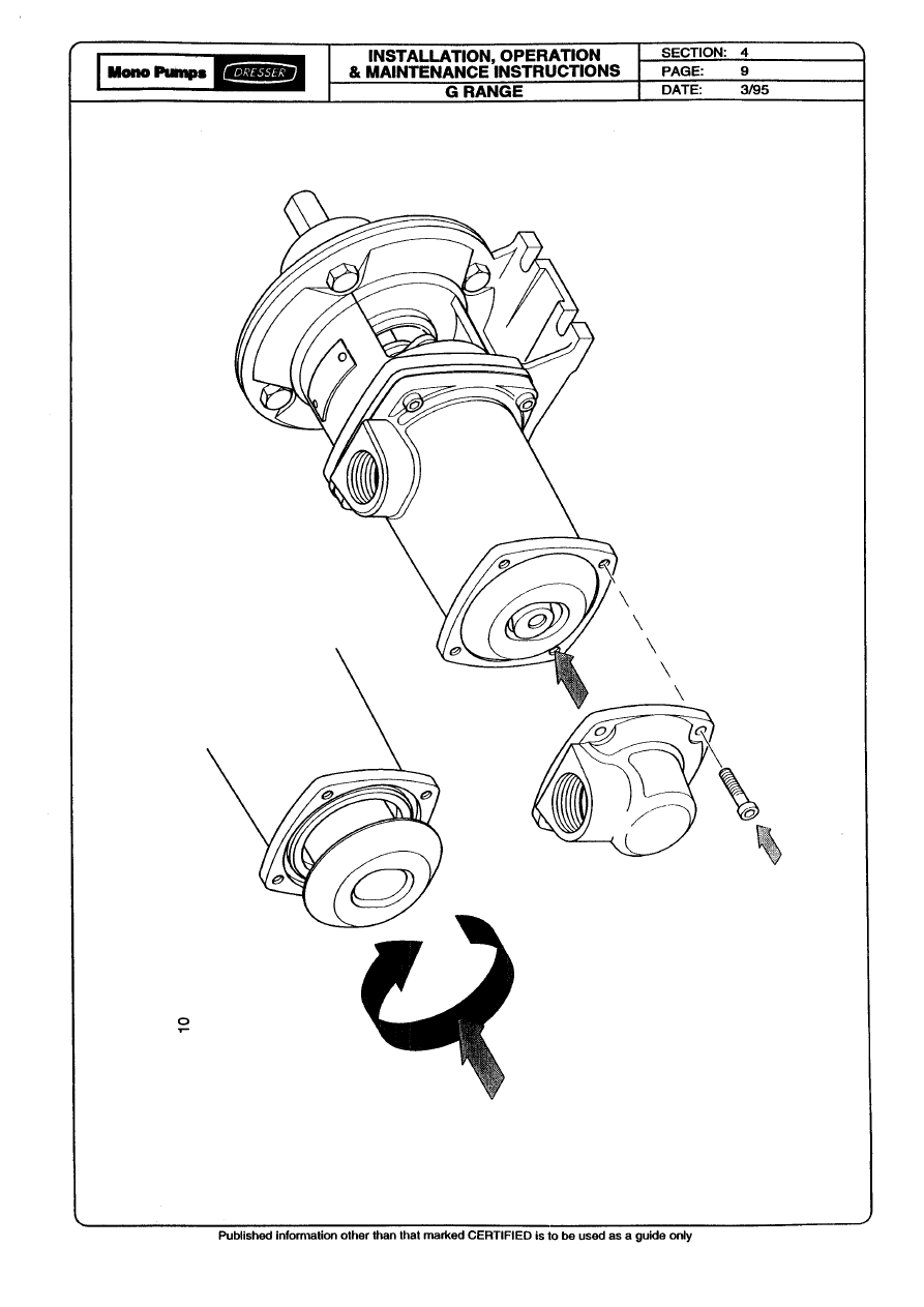
Dismantling & Assembly Diagrams
Section 4, Page 10
Issued - December 2000
10
Dismantling & Assembly Diagrams
Section 4, Page 11
Issued - December 2000
11
(Nm)
Dismantling & Assembly Diagrams
Section 4, Page 12
Issued - December 2000
12
Dismantling & Assembly Diagrams
Section 4, Page 13
Issued - August 2001
14
ALTERNATIVE
ROTOR
SUPPORT
-
SLING
13
(Nm)
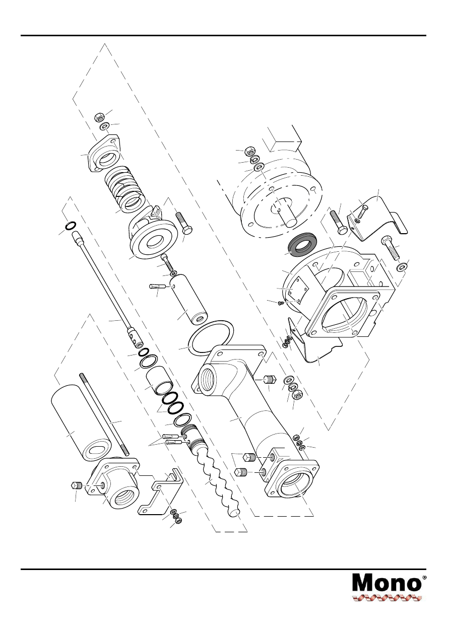
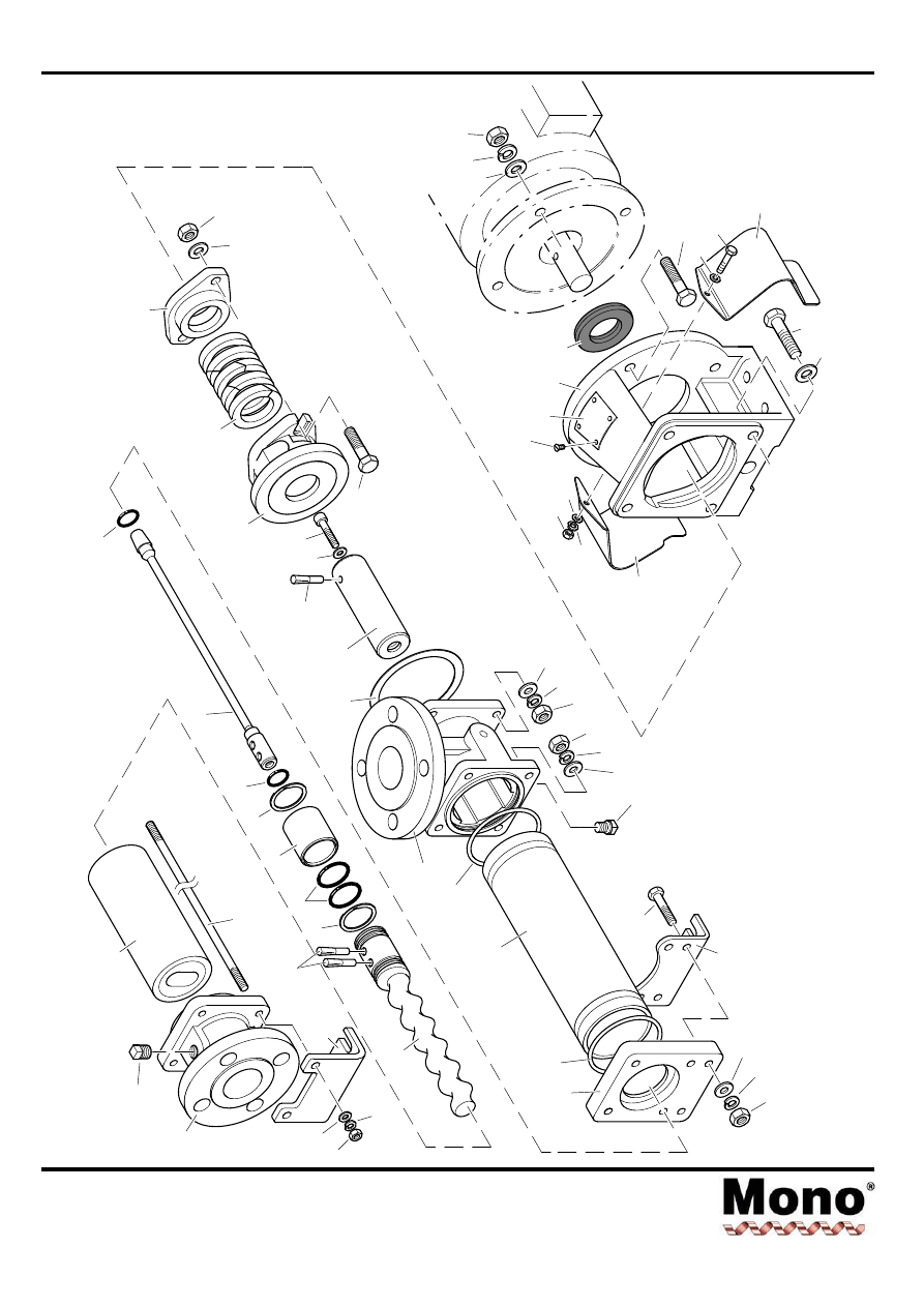
Exploded Views
Section 4, Page 14
Issued - December 2000
P501
24A
62A
P504
P505
P506
22A
95A
25A
P408
P407
P404
75A
P407
26A
P402
23A
P502
P509
P508
P507
P105
P107
P106
P503
20A
32A
P401
P405
P406
65A
10A
P201
08A
P203
P202
P109
P108
P102
15A
01A
42A
15A
P601
B012, B014, B021, B022
B024, B031,B03K, B032
P403
P603
P602
P604
P103
06A/06B
P106
P104
P102
P101
Exploded Views
Section 4, Page 15
Issued - December 2000
B024
24A
P504
P505
P506
47A
22A
95A
23A
47B
P501
24A
62A
P504
P505
P506
23A
P509
P508
P507
95A
22A
62B
B032
20C
20B
P509
P508
P507
62B
Exploded Views
Section 4, Page 16
Issued - August 2004
P501
62A
P504
P505
P506
22A
95A
25A
P407
P404
75A
P407
26A
P402
20A
32A
P401
P405
P406
65A
P201
08A
P203
P202
P106
P104
P109
P108
P102
15A
01A
42A
15A
P601
B0X1,
B0X2
24A
P403
P103
06A/06B
P408
P603
P602
P604
P105
P106
P107
P503
P507
P508
62B
P511
P512
P513
P509
23B
23A
P510
P515
76A
P514
10A
P102
P101
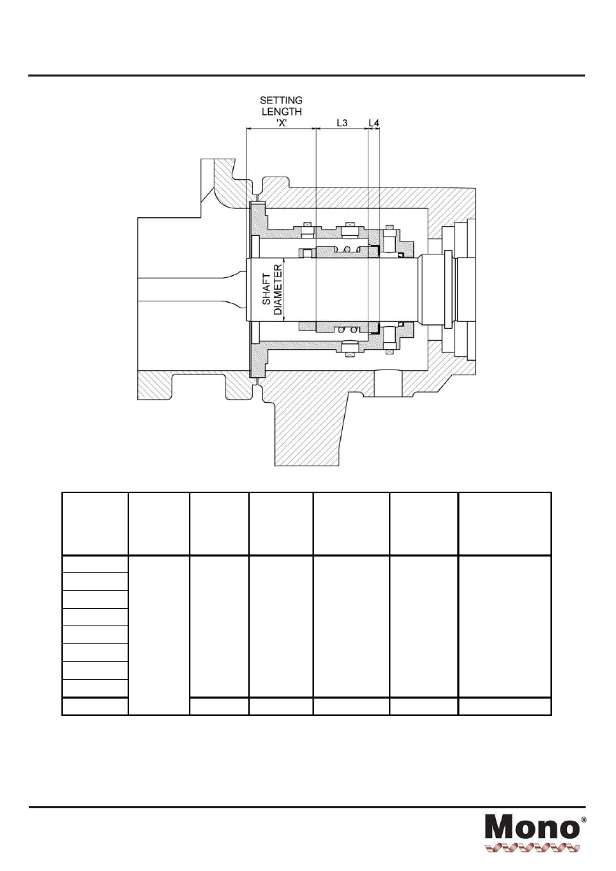
Setting Length - Mechanical Seal
Section 4, Page 17
Issued - January 2005
Note: All seal working lengths are to DIN L1K dimensions.
This table is not to be used for standard or DIN L1N working length seals.
All seals use 'M' type seats except for 85mm which uses 'BS' type.
This table is not necessarily compatible with any other seal type - check with Mono Pumps Technical Dept.
Pump
size
Drive
Type
Shaft dia.
mm
Seal Part
number
Seal working
length L3
mm
Seat length
L4
mm
Setting distance
'X'
mm
B012
B021
B022
B024
B031(MK2)
B032(MK2)
B03K
B0X1
32
M032139G
35.5
7
13.5
B0X2
Flexishaft
45
M045139G
37
8
44.0
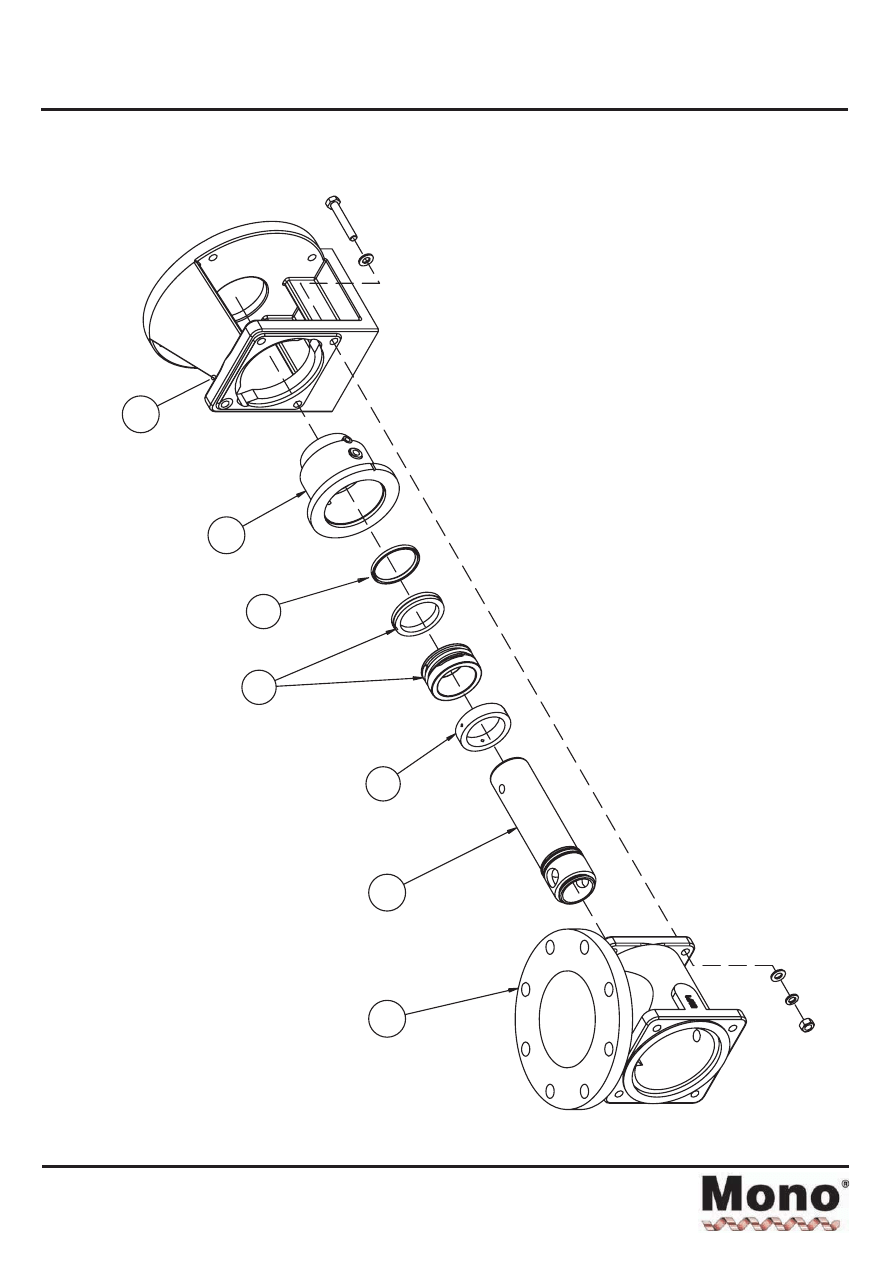
Exploded Views - Mechanical Seal
Section 4, Page 18
Issued - April 2002
23A
32A
66A
10A
65A
01A
10B

Torque Tightening Figures
Section 5, Page 1
Issued - August 2004
PUMP SIZE
SUCTION CHAMBER/
SUCTION EXT.
Nm
P105
STATOR TIE
BAR
Nm
P504, P507
**DRIVE END
FLEXISHAFT CAP
SCREW
Nm
P405
B012 10
4
15
B014 10
4
15
B021 10
4
15
B022 10
4
15
B024 10
4
15
B031 10
4
15
B03K 10
4
15
B032 10
4
15
B0X1 10
10
15
B0X2 11
10
15
Note: Torque tolerances are +/-5% of stated nominal figures.
**
Apply thread-locking compound to screw threads prior to assembly.

Mono Pumps Limited
Martin Street, Audenshaw,
Manchester, M34 5JA, England
Tel: +44 (0) 161 339 9000 Fax: +44 (0) 161 344 0727
E-mail: info@mono-pumps.com
www.mono-pumps.com
Issued - January 2005
Mono Pumps Around the World
Contacts:
MONO PUMPS LIMITED
Martin Street
Audenshaw
Manchester
England
M34 5JA
Tel: 0161 339 9000
Fax: 0161 344 0727
E-mail (general): info@mono-pumps.com
E-mail (service): service@mono-pumps.com
Web site: www.mono-pumps.com
MONO PUMPS (AUSTRALIA) PTY LTD
Mono House
338-348 Lower Dandenong Road
Mordialloc 3195
Victoria
Australia
Tel: +61 (0)3 9580 5211
Fax: +61 (0)3 9580 6659
E-mail: ozsales@mono-pumps.com
Web site: www.mono-pumps.com
NATIONAL OILWELL INC.
Room 2303
Capital Mansion
No. 6 Xin Yuan Southern Road
Chao Yang District
Beijing 100004
People’s Republic of China
Tel: +86 (0) 10 6461 1115
Fax: +86 (0) 10 8486 8481
MONOFLO, INC.
12000 West Little York
Houston
Texas 77041
USA
Tel: +1 713 466 7999
Fax: +1 713 466 3101
E-mail: inquire@monoflo.com
Web site: www.monoflo.com
MONO PUMPS (NEW ZEALAND) LTD
P.O. Box 71021, Rosebank
35-41 Fremlin Place
Avondale
Auckland 1230
New Zealand
Tel: +64 (0)9 829 0333
Fax: +64 (0)9 828 6480
E-mail: info@mono-pumps.co.nz
Web site: www.mono-pumps.com
NATIONAL OILWELL ELECTRICAL CONTROL
(SHANGHAI) CO. LTD
No. 500 YaGang Road
Lujia Village
Malu, Jiading District
Shanghai 201801
People’s Republic of China
Tel: +86 (0) 21 5915 7168
Fax: +86 (0) 21 5915 6863

JOWA 3SEP OWS
OILY WATER SEPARATOR
Standard
K:\1-NYA K\1-JOWA PRODUKTER\3SEP\Manual
38/41
14.0 10.0m3/h Pump Operating Manual

Mono
®
Installation, Operation and
Maintenance Instructions
Monobloc B (Sizes 04 and above)
OMMP/005/01/R13
English

Spares and Service Contact Details
Spares & Service
Issued - July 2001
Mono UK
Spares:
+44 (0)161 214 2380 (direct Line 8.15 am – 5.00 pm)
E-mail:
spares@mono-pumps.com
Service:
+44 (0)161 214 2390 (direct Line 8.15 am – 5.00 pm)
E-mail:
service@mono-pumps.com
Service:
+44 (0)161 339 9000 (24 hrs)
Mono Australia
Telephone
Facsimile
Melbourne
(03) 9580 5211
(03) 9580 9036
Sydney
(02) 9521 5611
(02) 9542 3649
Brisbane
(07) 3350 4582
(07) 3350 3750
Adelaide
(08) 8447 8333
(08) 8447 8373
Perth
(08) 9479 0444
(08) 9479 0400
Darwin
(08) 8984 3099
(08) 8947 0540
Tasmania
(03) 6249 8704
(03) 6249 8756
E-mail:
ozsales@mono-pumps.com
Monoflo USA
Spares & Service:
+1 281 599 4700
E-mail:
inquire@monoflo.com
Mono New Zealand
Spares & Service:
+64 (0)9 829 0333
E-mail:
info@mono-pumps.com

Index
Index
Issued - December 2000
SECTION 1
INSTALLATION
START-UP PROCEDURE
ASSEMBLY AND DISMANTLING ADVICE
SECTION 2
FAULT FINDING
SECTION 3
DRAWING REFERENCE NUMBERS
SECTION 4
DISMANTLING AND ASSEMBLY DIAGRAMS
EXPLODED VIEWS
SECTION 5
TORQUE TIGHTENING FIGURES
SECTION 6
MONO PRODUCTS
Declaration
Manufacturer’s Declaration
Mono Manufacturer’s Declaration as required by the
EEC Machine Directive 98/37/EC, Annex ll B:
The Mono machines delivered in accordance with our
design are intended to be fitted in one machine or
assembled together with other machines to form one
machine/plant.
The machinery must not be put into service until the
machinery into which it is to be incorporated has been
declared in conformity with the provisions of the
Directive.
Particular attention must be paid to the safety
requirements specified in EN 809 (Pumps and Pump
Equipment for Fluids) as well as the information in
these operating instructions.
Signed: G D Thomas
Chief Engineer
Declaration of Conformity
Mono machines that do not possess any safety
accessories do not fulfil the requirements of the EEC
Machine Directive 98/37/EC.
For this reason, no Declaration of Conformity as
required by the EEC Machine Directive 98/37/EC
Annex ll A can be issued before appropriate safety
devices have been installed/mounted on the machine
and/or plant with due regard to the information given in
these operating instructions.
The following harmonised standards are particularly
applicable:
EN 809, EN292T1, EN292T2
Applicable national standards and specifications must
be taken into consideration.
Following assessment of the conformity of the
machine/plant with the EEC Machine Directive,
customers may on their own initiative place on the full
machine/plant the EEC symbol ‘CE’ as defined in
Identification Directive 93/68/EEC.

Installation, Operation & Maintenance Instructions
Section 1, Page 1
Issued - March 2002
INSTALLATION
1.1
INSTALLATION AND SAFETY
RECOMMENDATIONS
In common with other items of process plant a pump
must be installed correctly to ensure satisfactory and
safe operation. The pump must also be maintained
to a suitable standard. Following these
recommendations will ensure that the safety of
personnel and satisfactory operation of the pump is
achieved.
1.2.1.
GENERAL
When handling harmful or objectionable materials,
adequate ventilation must be provided in order to
disperse dangerous concentrations of vapours. It is
recommended that wherever possible, Mono pumps
should be installed with provision for adequate
lighting, thus ensuring that effective maintenance
can be carried out in satisfactory conditions. With
certain product materials, a hosing down facility with
adequate draining will simplify maintenance and
prolong the life of pump components.
1.2.2.
SYSTEM DESIGN & INSTALLATION
At the system design stage, consideration must be
given to provision of filler plugs, and the installation
of non-return and/or isolating valves. The pumps
must also be protected by suitable devices against
over pressure and dry running.
i.
HORIZONTAL MOUNTING
All ranges excluding P Range Mono pumps are
normally installed in a horizontal position with
baseplates mounted on a flat surface, grouted in
and bolted, thus ensuring firm fixing and a reduction
in noise and vibration.
The unit should be checked after bolting down to
ensure that the alignment of the pump to its prime
mover is correct.
ii.
VERTICAL MOUNTING
P Range Pumps Only
The P range pumps are intended for vertical
installation. Care must be taken when lifting the
pump into the vertical position. Normally ‘P’ range
pumps will be designed with a sole plate that will be
bolted to the customers framework.
If the pump is to be mounted in any way other than
described above, confirmation of the installation
must be agreed with Mono Pumps Limited. All the
pipework should be independently supported.
1.3.1 HANDLING
During installation and maintenance, attention must
be paid to the safe handling of all items. Where a
pump or its components weigh in excess of 20 kg
(45lb) it is recommended that suitable lifting tackle
should be used to ensure that personal injury or
damage to components does not occur.
For safe handling of both bareshaft pumps and
pump units (pump/ gearbox/motor etc.) slings should
be used. The position of the slings will depend upon
the specific pump/unit construction and should be
carried out by personnel with the relevant
experience to ensure that the pump is not damaged
and injury to personnel does not occur.
If eyebolts do exist then these should only be used
for lifting the individual components for which they
are supplied.
1.3.2 STORAGE
SHORT TERM STORAGE
Where a pump has to be stored for 6 months or
less then the following steps are advised:-
1.
Store pump inside wherever possible or if this is not
feasible then provide protective covering. Do not
allow moisture to collect around the pump.
2.
Remove the drain plug, if fitted. Any inspection
plates fitted should also be removed to ensure that
the suction housing can drain and dry completely.
3.
Loosen the packed gland and inject sufficient grease
into the stuffing box. Tighten the gland nut hand
tight. If a water flush system is to be used do not
grease, a small amount of light oil is recommended
for these.
4.
See Manufacturers Instructions for
motor/gearbox/drive instructions for storage
procedures.
Installation, Operation & Maintenance Instructions
Section 1, Page 2
Issued - March 2002
LONG TERM STORAGE
If the pump is to be kept in storage for more than six
months then in addition to the above the following
procedures should be carried out regularly (every 2 -
3 weeks if possible):
1.
If practicable rotate the pump at least three quarters
of one revolution to avoid the rotor setting in the
stator.
2.
Note, however, that the pump is not to be rotated for
more than two revolutions each time because
damage could be caused to the rotor/ stator
elements.
IMMEDIATELY PRIOR TO INSTALLATION AND
STARTING
Before installing the pump please ensure that all
plugs and inspection plates are replaced and
that excess grease/oil is removed from the
stuffing box.
1.4 ELECTRICAL
Electrical connection should only be made using
equipment suitable for both rating and environment.
Where any doubts exist regarding the suitability of
equipment, Mono Pumps Limited, should be
consulted before proceeding. Normally the Mono
pump should be installed with starting equipment
arranged to give direct on line starting.
Earthing points will be provided on electric drives (if
supplied) and it is essential that these are correctly
connected. When the motor is being wired and
checked for rotation, the start/stop sequence must
be instantaneous to prevent dry running (see 2) or
pressurising upstream equipment. (Check direction
arrow on pump nameplate). The electrical
installation should include appropriate isolating
equipment to ensure that the pump unit is safe to
work on.
1.5
PRESSURE RELIEF VALVES AND NON-RETURN
VALVES
1.
It is recommended that a suitable safety device is
installed on the discharge side of the pump to
prevent over-pressurisation of the system.
2.
It is also recommended that a non-return valve is
installed on the discharge side of the pump to
prevent reverse flow through the system.
When both are installed it is advised that the relief
valve is positioned closer to the pump than the non-
return valve.
IMPORTANT
The pump must never run against a closed inlet
or outlet valve, as this could result in
mechanical failure.
1.6
GENERAL SAFETY
GREAT CARE MUST BE TAKEN TO PROTECT
ALL ELECTRICAL EQUIPMENT FROM
SPLASHING WHEN HOSING DOWN. WHERE
MONO PUMPS LIMITED HAVE SUPPLIED A
BARESHAFT PUMP THE ONUS IS ON THE USER
TO FIT ADEQUATE GUARDS IN COMPLIANCE
WITH THE REQUIREMENTS OF THE RELEVANT
REGULATIONS.
All nuts and bolts, securing flanges and base
mounting fixtures must be checked for tightness
before operation. To eliminate vibration, the pump
must be correctly aligned with the drive unit, and all
guards must be securely fixed in position. When
commissioning the plant, all joints in the system
must be checked thoroughly for leakage.
If, when starting, the pump does not appear to
operate correctly (see 2), the plant must be shut
down immediately and the cause of the malfunction
established before operations are recommenced. It
is recommended that depending upon plant system
operation, either a combined vacuum and pressure
gauge, or a vacuum gauge only be fitted to the
pump inlet port, and a pressure gauge fitted to the
outlet port, these will then continuously monitor the
pump operating conditions.
1.7
DUTY CONDITIONS
Pumps should only be installed on duties for which
Mono Pumps Limited have specified the materials of
construction, flow rates, pressure, temperature,
speed etc. Where dangerous materials are to be
pumped, consideration must be given to the safe
discharge from relief valves, gland drains etc.
IF THE DUTY SHOULD BE CHANGED, MONO
PUMPS LIMITED SHOULD BE CONTACTED AND
THEIR RECOMMENDATIONS SOUGHT IN THE
INTEREST OF APPLICATION, SAFETY OF
PLANT, EFFICIENCY AND PUMP LIFE.

Installation, Operation & Maintenance Instructions
Section 1, Page 3
Issued - March 2002
2.
START-UP PROCEDURE
Pumps must be filled with liquid before starting. The
initial filling is not for priming purposes, but to
provide the necessary lubrication of the stator until
the pump primes itself. When the pump is stopped,
sufficient liquid will normally be trapped in the
rotor/stator assembly to provide lubrication upon re-
starting.
If, however, the pump has been left standing for an
appreciable time, moved to a new location, or has
been dismantled and re-assembled, it must be
refilled with liquid and given a few turns before
starting. The pump is normally somewhat stiff to
turn by hand owing to the close rotor/stator fit.
However, this stiffness disappears when the pump is
running normally against pressure.
2.1
DRY RUNNING
NEVER RUN THE PUMP IN A DRY CONDITION
EVEN FOR A FEW REVOLUTIONS OR THE
STATOR WILL BE DAMAGED IMMEDIATELY.
CONTINUAL DRY RUNNING COULD PRODUCE
SOME HARMFUL OR DAMAGING EFFECTS.
2.2
ROTATION PUMP ROTATION DETAILS
PUMP RANGE
BI-DIRECTIONAL
COMMENT
E
Yes
Monobloc B
Yes
Merlin Industrial
Yes
S, SL
Yes
LF
Yes
W
No
**
Merlin Widethroat
No
**
MM ML
No
*
MS
No
**
G
No
*
CB/SB
No
*
Placer
No
**
Grout Injection
No
**
P
No
*
CP0011
No
**
CP0025,CP0800,CP1600
No
*
*
Clockwise when viewed from drive end.
**
Anti-clockwise when viewed from drive end.
DIRECTIONS OF ROTATION
BEFORE THE DIRECTION OF ROTATION IS
CHANGED, MONO PUMPS LIMITED MUST BE
CONSULTED SO THAT THE SUITABILITY OF
THE PUMP CAN BE CONFIRMED WHEN
OPERATING ON THE NEW DUTY.
2.3.1.
GLAND PACKING
Where a pump is supplied fitted with gland packing
(manufactured from a non-asbestos material), the
gland will require adjustment during the initial
running in period. Newly packed glands must be
allowed to ‘run-in’ with only finger tight compression
on the gland follower nuts. This should continue for
about 3 days. The gland follower should be
gradually tightened over the next week to achieve a
leakage rate as shown in the table below. Gland
followers should be adjusted at regular intervals to
maintain the recommended leakage flow rate.
Under normal working conditions a slight drip from
the gland under pressure assists in cooling and
lubricating the packing. A correctly adjusted
gland will always have small leakage of fluid.
Typical Leakage Rates from Packed Glands
Up to 50mm shaft diameter
2 drops per minute
50 – 75mm shaft diameter
3 drops per minute
75 – 100mm shaft diameter
4 drops per minute
100 – 125mm shaft diameter
5 drops per minute
125 – 160mm shaft diameter
6 drops per minute
A gland drip is, however, undesirable when handling
corrosive, degreasing, or abrasive materials. Under
these conditions the gland must be tightened the
minimum amount whilst the pump is running to
ensure satisfactory sealing when under pressure, or
to stop entry of air when under suction conditions.
The gland leakage of toxic, corrosive or hazardous
liquids can cause problems of compatibility with the
pumps materials of construction.
Provision of a gland drain should be considered,
especially for the leakage of hazardous products.
CARE IS REQUIRED WHEN ADJUSTING THE
GLAND WHILST PUMP IS RUNNING.
2.3.2
MECHANICAL SEALS - ALL PUMPS
When a mechanical seal is fitted to the pump it may
be necessary to provide a barrier fluid to some part
of the seal. This should be provided in line with the
seal manufacturers instructions.
2.4.
GUARDS
In the interests of safety, and in accordance with the
U.K. Health and Safety at Work Act 1974, all guards
must be replaced after necessary adjustments have
been made to the pump.

Installation, Operation & Maintenance Instructions
Section 1, Page 4
Issued - March 2002
2.5
WARNING/CONTROL DEVICE
Prior to operating the pump, if any warning or control
devices are fitted these must be set in accordance
with their specific instructions.
2.6
PUMP OPERATING TEMPERATURE
The range of temperatures the pump surfaces will
develop is dependent upon factors such as product
temperature and ambient temperature of the
installation. There may be instances where the
external pump surface can exceed 50oC.
In these instances, personnel must be made aware
of this and suitable warnings/guarding used.
2.7
NOISE LEVELS
1.
The noise sound pressure level will not exceed
85dB at one metre distance from the pump.
2.
This is based on a typical installation and does not
necessarily include noise from other sources or any
contribution from building reverberation.
3.
For pumps identified below, the noise levels vary
between 85 and 95dB but will not exceed 95dB at
one metre distance from the pump.
Pump Sizes (based on E Range Pumping
Element)
Single Stage
Size 12 and above
Two Stage
Size 9 and above
Four Stage
Size 7 and above
Six Stage
Size 7 and above
Eight Stage
Size 6 and above
2.8
LUBRICATION
Pumps fitted with bearings should be inspected
periodically to see if grease replenishment is
necessary, and if so, grease should be added until
the chambers at the ends of the bearing spacer are
approximately one third full.
Periodic bearing inspection is necessary to maintain
optimum bearing performance. The most expedient
time to inspect is during periods of regular
scheduled equipment downtime - for routine
maintenance or for any other reason.
Under tropical or other arduous conditions, however,
a more frequent examination may be necessary. It
is therefore advisable to establish a correct
maintenance schedule or periodic inspection.
BP LC2 / Mobilgrease XHP 222 or their equivalent
must be used for replenishment.
2.9
PUMP UNITS
Where a pump unit is dismantled and re-assembled,
consideration must be given to ensure that where
appropriate the following steps are covered.
1.
Correct alignment of pump/gearbox
2.
Use of appropriate couplings & bushes
3.
Use of appropriate belts & pulleys correctly
tensioned.
2.10
CLEANING PRIOR TO OPERATION
i.
Non Food Use
During the commissioning of a new pump or
recommissioning of an overhauled pump, it is
advisable to clean the pump prior to the initial
operation of the pump in the process.
ii.
Food Use
When a pump has been supplied for a food
application, it is important to ensure that the pump is
clean prior to initial operation of the pump.
Therefore, it is important that a clean-in-place
treatment is executed on the pump at the following
times:-
1.
When the pump is first commissioned for use.
2.
When any spare components are fitted into the
wetted area of the pump.
A recommended CIP procedure is as follows:
This procedure should not be used on the CP
Pump Range. Please consult our application
engineers for a suitable procedure.
Caustic Wash
LQ94 ex Lever Diversey or equivalent
2% concentration
Acid Wash
P3 Horolith 617 ex Henkel
Ecolab or equivalent 1% concentration
Procedure
1. Caustic wash @ 75°C for 20 mins
2.
Water rinse @ 80°C for 20 mins

Installation, Operation & Maintenance Instructions
Section 1, Page 5
Issued - March 2002
3.
Acid wash @ 50°C for 20 mins
4.
Water rinse @ 80°C for 20 mins
•
CIP flow rates (hence pump
speeds) should be maximised to achieve highest
level of cleanability.
Pumps fitted with CIP by pass ports will permit
higher flow rates without the need to increase pump
speed.
•
The use of ‘neat active’ caustic
and acid chemicals is not
recommended. Proprietary cleaning
agents should be used in line with manufacturers
instructions.
•
All seals and gaskets should be
replaced with new if disturbed
during maintenance.
•
Pump internals should be regularly inspected to
ensure hygienic integrity is maintained, especially
with respect to elastomeric components and seals,
and replaced if necessary.
The four stages constitute one cycle and we
recommend that this cycle is used to clean the pump
before use on food.
Once the pump has been commissioned, the
cleaning process will depend upon the application.
The user must therefore ensure that their cleaning
procedures are suitable for the duty for which the
pump has been purchased.
2.11
WIDETHROAT PUMPS
Specific pumps may have auger feed screws, with
or without a bridge breaker system to feed the
pumping element. If the pump installation requires
that these cannot be enclosed, care must be taken
to ensure personnel cannot gain access whilst the
pump is operating. If this is not possible an
emergency stop device must be fitted nearby.
2.12
EXPLOSIVE PRODUCTS/ HAZARDOUS
ATMOSPHERES
In certain instances the product being pumped may
well be of a hazardous nature.
In these installations consideration must be given to
provide suitable protection and appropriate warnings
to safeguard personnel and plant.
2.13 ACCESS
PORTS
Where access ports are fitted then the following
steps must be followed prior to removal:
1.
Pump must be shut down and the electrical supply
isolated.
2.
Protective clothing should be worn, especially if the
pumped product is obnoxious.
3.
Remove access plate with care utilising where
possible drip trays to collect product leakage.
Access ports are included to assist in removing
blockages and to allow a visual check on the
components within the suction chamber.
It is not to be considered as an additional method in
dismantling the pump.
Re-assembly of the plate should be completed using
new gaskets prior to the pump being switched on.
2.14
ADJUSTABLE STATORS
If adjustable stators are fitted then the following
steps must be followed for adjusting the clamping
devices.
The adjustable stator assembly is designed to give
an even compression around the stator
circumference. It is designed to be used when
pump performance reduces through wear to an
unacceptable level, to restore the required flow rate.
The stator compression is increased using the
following steps:-
1.
Release the six locking screws half a turn.
2.
Tighten the eight clamp screws until adjustment
allowed by releasing the lock screws has been taken
up.
3.
Repeat steps 1 and 2 until the pump performance
has been restored to its former level.
NOTE
It is imperative that when adjusting the stator that
only sufficient pressure is placed on the stator to
enable the capacity of the pump to be reinstated.
Over tightening of the stator could easily result in
damage to the driver by overload and so extreme
care must be taken when carrying out these
adjustments.

Installation, Operation & Maintenance Instructions
Section 1, Page 6
Issued - March 2002
It is therefore advisable to make the adjustment
while the pump is running and power readings can
be monitored.
REMOVAL OF ADJUSTABLE STATOR
The procedure for removal of an adjustable stator is
the same as that of a standard one, except it is
necessary to remove the clamp plates before the
stator can be twisted off the rotor.
This can be done by undoing the clamp screws;
then releasing the clamp plate by using the locking
screws as jacking screws to remove the clamp
plates.
Re-assembly will be done using the reverse
procedure.
2.15
MAINTENANCE OF WEARING COMPONENTS
2.15.1
ROTOR AND STATOR
The wear rate on these components is dependent
on many factors, such as product abrasivity, speed,
pressure etc.
When pump performance has reduced to an
unacceptable level one or possibly both items will
need replacing.
2.15.2
DRIVE SHAFT - PACKED GLAND
The wear rate of the gland area is dependent on
many factors such as product abrasivity and speed.
Regular gland maintenance will maximise the life of
the shaft. Replacement of both the gland packing
and shaft will be necessary when shaft sealing
becomes difficult to achieve.
2.15.3
COUPLING ROD JOINTS
Regular maintenance and lubrication will maximise
life of the joints.
Replacement of one or both joint assemblies and
possibly the coupling rod may be necessary when
wear is apparent.
It is essential to replace all the joint items with
genuine Mono parts to ensure maximum life.
2.15.4
FLEXISHAFT DRIVE PUMPS
With this design there are no wearing items to
replace in the drive train, however, if during routine
inspection the shaft is visibly damaged / distorted
or the protective coating is damaged, then this item
should be replaced to avoid unexpected
breakdowns.
3.0
ASSEMBLY AND DISMANTLING
Section 4 contains the steps to dismantle and
re-assemble the pump. All fastenings must be
tightened securely and when identified the
appropriate torque figures should be used.
3.1
USE OF ITEMS NOT APPROVED OR
MANUFACTURED BY MONO PUMPS LIMITED
The pump and its components have been designed
to ensure that the pump will operate safely within the
guidelines covered by the legislation.
As a consequence Mono Pumps Limited have
declared the machine safe to use for the duty
specified as defined by the Declaration of
Incorporation or Conformity that is issued with this
Instruction Manual.
The use of replacement items that are not approved
by or manufactured by Mono Pumps Limited may
affect the safe operation of the pump and it may
therefore become a safety hazard to both operators
and other equipment. In these instances the
Declaration provided will therefore become invalid.
The guarantee referenced in the Terms and
Conditions of Sale will also be invalidated if
replacement items are used that are not approved or
manufactured by Mono Pumps Limited.
DISPOSAL OF WORN COMPONENTS
When replacing wearing parts, please ensure
disposal of used parts is carried out in compliance
with local environmental legislation. Particular care
should be taken when disposing of lubricants.

Diagnostic Chart
Section 2, Page 1
Issued - December 2000
SYMPTOMS
POSSIBLE CAUSES
1.
NO DISCHARGE
2.
LOSS OF CAPACITY
3.
IRREGULAR DISCHARGE
4.
PRIMING LOST AFTER START
5.
PUMP STALLS AT START UP
6.
PUMP OVERHEATS
7.
MOTOR OVERHEATS
8.
EXCESSIVE POWER ABSORBED BY PUMP
9.
NOISE AND VIBRATION
10.
PUMP ELEMENT WEAR
11.
EXCESSIVE GLAND OR SEAL WEAR
12.
GLAND LEAKAGE
13.
SEIZURE
1. 2. 3. 7. 26. 28. 29.
3. 4. 5. 6. 7. 8. 9. 10. 22. 13. 16. 17. 21. 22. 23. 29
3. 4. 5. 6. 7. 8. 13. 15. 29.
3. 4. 5. 6. 7. 8. 13. 15
8. 11. 24.
8. 9. 11. 12. 18. 20
8. 11. 12. 15. 18. 20.
8. 11. 12. 15. 18. 20
3. 4. 5. 6. 7. 8. 9. 11. 13. 15. 18. 19. 20. 22. 23. 27. 31
9. 11.
12. 14. 25. 30.
13. 14.
9. 11. 12. 20.
LIST OF CAUSES
REMEDIAL ACTIONS
1.
INCORRECT DIRECTION OF ROTATION
2.
PUMP UNPRIMED
3.
INSUFFICIENT N.P.S.H. AVAILABLE
4.
PRODUCT VAPORISING IN SUPPLY LINE
5.
AIR ENTERING SUPPLY LINE
6.
INSUFFICIENT HEAD ABOVE SUPPLY VESSEL OUTLET
7.
FOOTVALVE/STRAINER OBSTRUCTED OR BLOCKED
8.
PRODUCT VISCOSITY ABOVE RATED FIGURE
9.
PRODUCT TEMP. ABOVE RATED FIGURE
10.
PRODUCT VISCOSITY BELOW RATED FIGURE
11.
DELIVERY PRESSURE ABOVE RATED FIGURE
12.
GLAND OVERTIGHT
13.
GLAND UNDERTIGHT
14.
GLAND FLUSHING INADEQUATE
15.
PUMP SPEED ABOVE RATED FIGURE
16.
PUMP SPEED BELOW RATED FIGURE
17.
BELT DRIVE SLIPPING
18.
COUPLING MISALIGNED
19.
INSECURE PUMP/DRIVE MOUNTING
20.
SHAFT BEARING WEAR/FAILURE
21.
WORN PUMP ELEMENT
22.
RELIEF VALVE CHATTER
23.
R.V. INCORRECTLY SET
24.
LOW VOLTAGE
25.
PRODUCT ENTERING PACKING AREA
26.
DRIVE TRAIN BREAKAGE
27.
NEGATIVE OR VERY LOW DELIVERY HEAD
28.
DISCHARGE BLOCKED/VALVE CLOSED
29.
STATOR TURNING
30.
STUFFING BOX “EATS” PACKING
31.
VEE BELTS
1.
REVERSE MOTOR
2.
BLEED SYSTEM OF AIR/GAS
3.
INCREASE SUCTION HEAD OR REDUCE SPEED/TEMP.
4.
INCREASE N.P.S.H. AVAILABLE (SEE 3 ABOVE)
5.
CHECK PIPE JOINTS/GLAND ADJUSTMENT
6.
RAISE VESSEL/INCREASE PIPE SIZE
7.
CLEAN OUT SUCTION LINE/VALVES
8.
DECREASE PUMP SPEED/INCREASE TEMP.
9.
COOL THE PRODUCT
10.
INCREASE PUMP SPEED/REDUCE TEMP.
11.
CHECK FOR BLOCKAGES IN DELIVERY LINE
12.
ADJUST GLAND SEE O&M INSTRUCTIONS
13.
ADJUST GLAND SEE O&M INSTRUCTIONS
14.
CHECK FLUID FLOWS FREELY INTO GLAND
15.
DECREASE PUMP SPEED
16.
INCREASE PUMP SPEED
17.
RE-TENSION BELTS
18.
CHECK AND ADJUST ALIGNMENT
19.
CHECK AND TIGHTEN ALL PUMP MOUNTINGS
20.
REPLACE BEARINGS
21.
FIT NEW PARTS
22.
CHECK CONDITION OF VALVE/RENEW
23.
RE-ADJUST SPRING COMPRESSION
24.
CHECK VOLTAGE/WIRING SIZES
25.
CHECK PACKING CONDITION AND TYPE
26.
CHECK AND REPLACE BROKEN COMPONENTS
27.
CLOSE DELIVERY VALVE SLIGHTLY
28.
REVERSE PUMP/RELIEVE PRESSURE/CLEAR BLOCKAGES
29.
REPLACE WORN PARTS/TIGHTEN UP STATOR BOLTS
30.
CHECK FOR WORN SHAFT AND REPLACE
31.
CHECK AND ADJUST TENSION OR REPLACE

Drawing Reference Numbers
Section 3, Page 1
Issued - March 2002
DRG.
REF
DESCRIPTION
DRG.
REF
DESCRIPTION
01A
01B
01C
06A
06B
08A
10A
10B
11A
15A
20A
20B
22A
22B
23A
23B
24A
25A
26A
27A
27B
27C
27D
28A
28B
29A
29B
29C
32A
32B
35A
42A
62A
62B
65A
65B
75A
75B
76A
95A
P101
P102
P103
P104
P105
P106
P107
P108
P109
P110
BODY
BEARING HOUSING
BODY ADAPTOR
NAMEPLATE (SOG)
NAMEPLATE (DOG)
GLAND FOLLOWER
GLAND PACKING
MECHANICAL SEAL
BEARING COVER
THROWER GUARD
GASKET - ADAPTOR
GASKET - GLAND
STATOR
STATOR
SUCTION CHAMBER
SUCTION CHAMBER EXTENSION
END COVER
ROTOR
COUPLING ROD
COUPLING ROD BUSH
COUPLING ROD BUSH
ROTOR SHAFT BUSH
ROTOR SHAFT BUSH
SEALING COVER
SEALING COVER
COUPLING ROD PIN
COUPLING ROD PIN
SHAFT PIN
SHAFT
DRIVE SHAFT
BEARING SPACER
THROWER
SUPPORT FOOT
SUPPORT FOOT
GLAND SECTION
ABUTMENT RING
ROTOR SLEEVE SHAFT
ROTOR SLEEVE SHAFT
ADAPTOR FLANGE
TIE ROD
HEX HD SCREW
PLAIN WASHER
RD HD DRIVE SCREW
HEX HD BOLT
HEX NUT
PLAIN WASHER
SPRING WASHER
SPRING WASHER
HEX NUT
BEARING
P111
P112
P113
P120
P121
P122
P123
P124
P125
P201
P202
P203
P401
P402
P403
P404
P405
P406
P407
P420
P421
P501
P502
P503
P504
P505
P506
P507
P508
P509
P510
P511
P512
P513
P514
P515
P516
P517
P518
P519
P520
P521
P522
P523
P524
P525
P526
P527
P528
P529
P530
BEARING
LIPSEAL
LIPSEAL
HEX HEAD BOLT
SPRING WASHER
PLAIN WASHER
HEX NUT
HEX HEAD BOLT
SPRING WASHER
HEX HD BOLT
HEX NUT
PLAIN WASHER
SEAL RING
SEAL RING
SPRING RETAINING CLIP
SPRING RETAINING CLIP
TIE SEALING COVER
TIE SEALING COVER
KEY
LOCKNUT
LOCKING WASHER
TAPER PLUG
TAPER PLUG
HEX NUT
PLAIN WASHER
SPRING WASHER
HEX NUT
PLAIN WASHER
SPRING WASHER
TOROIDAL SEAL RING
TOROIDAL SEAL RING
HEX HD BOLT
SPRING WASHER
PLAIN WASHER
HEX NUT
HEX HD BOLT
SPRING WASHER
PLAIN WASHER
HEX NUT
HEX HD BOLT
SPRING WASHER
PLAIN WASHER
HEX NUT
STUD
SPRING WASHER
PLAIN WASHER
HEX NUT
STUD
SPRING WASHER
PLAIN WASHER
HEX NUT
IMPORTANT NOTE
THE DRAWING REFERENCES SHOWN GIVE THE DESCRIPTION OF ALL THE PARTS DETAILED ON THE SECTIONAL
DRAWINGS IN THIS SECTION OF THE BOOK. THEREFORE SOME OF THE REFERENCES MAY NOT BE SHOWN ON
ANY ONE.
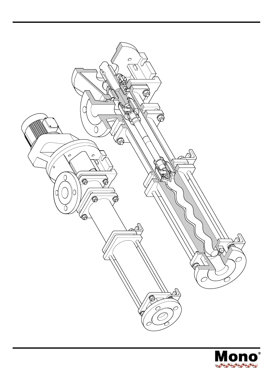
Dismantling & Assembly Diagrams
Section 4, Page 1
Issued - December 2000
'B' RANGE
04-12
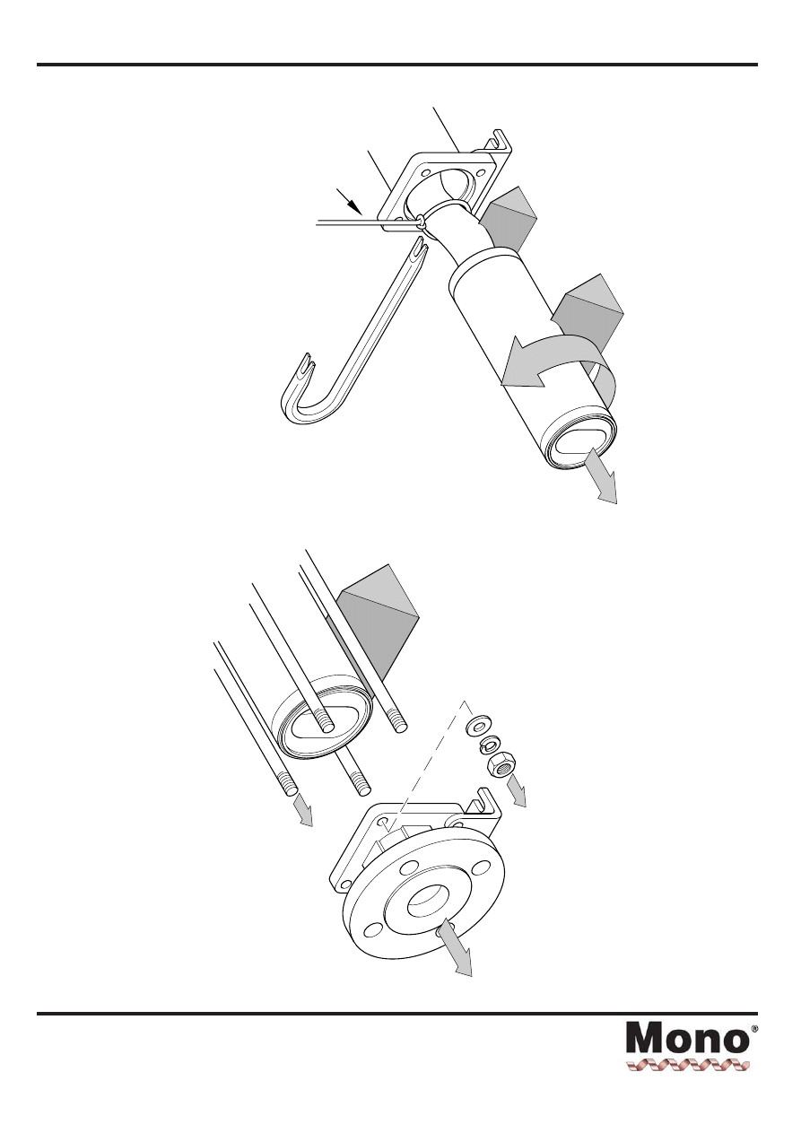
Dismantling & Assembly Diagrams
Section 4, Page 2
Issued - August 2001
DISMANTLING
PROCEDURE
ALTERNATIVE
ROTOR
SUPPORT
-
S
LING
1
2
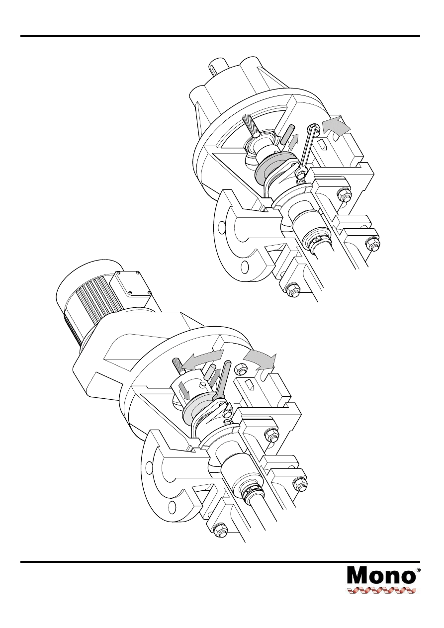
Dismantling & Assembly Diagrams
Section 4, Page 3
Issued - December 2000
3
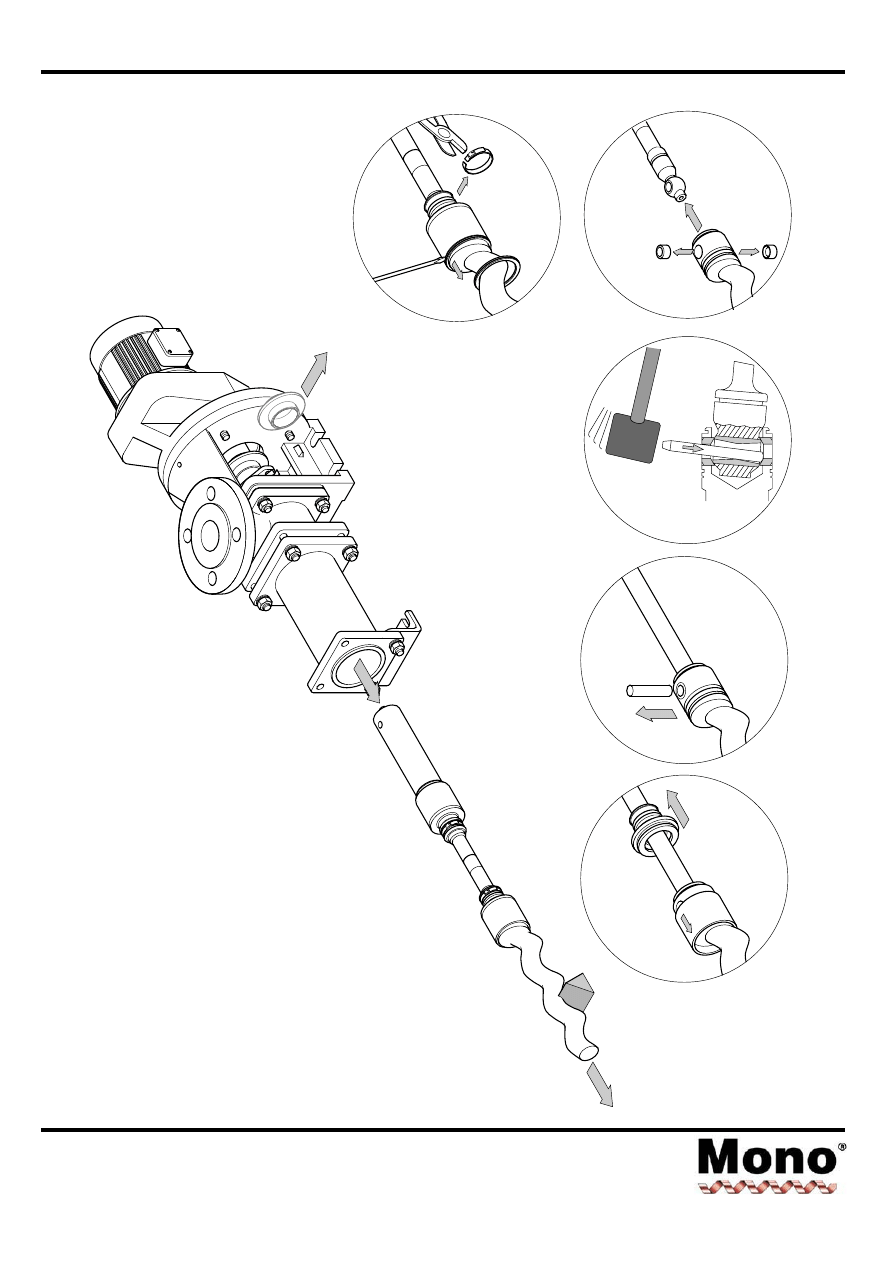
Dismantling & Assembly Diagrams
Section 4, Page 4
Issued - December 2000
4a
4c
4d
4e
4f
4b
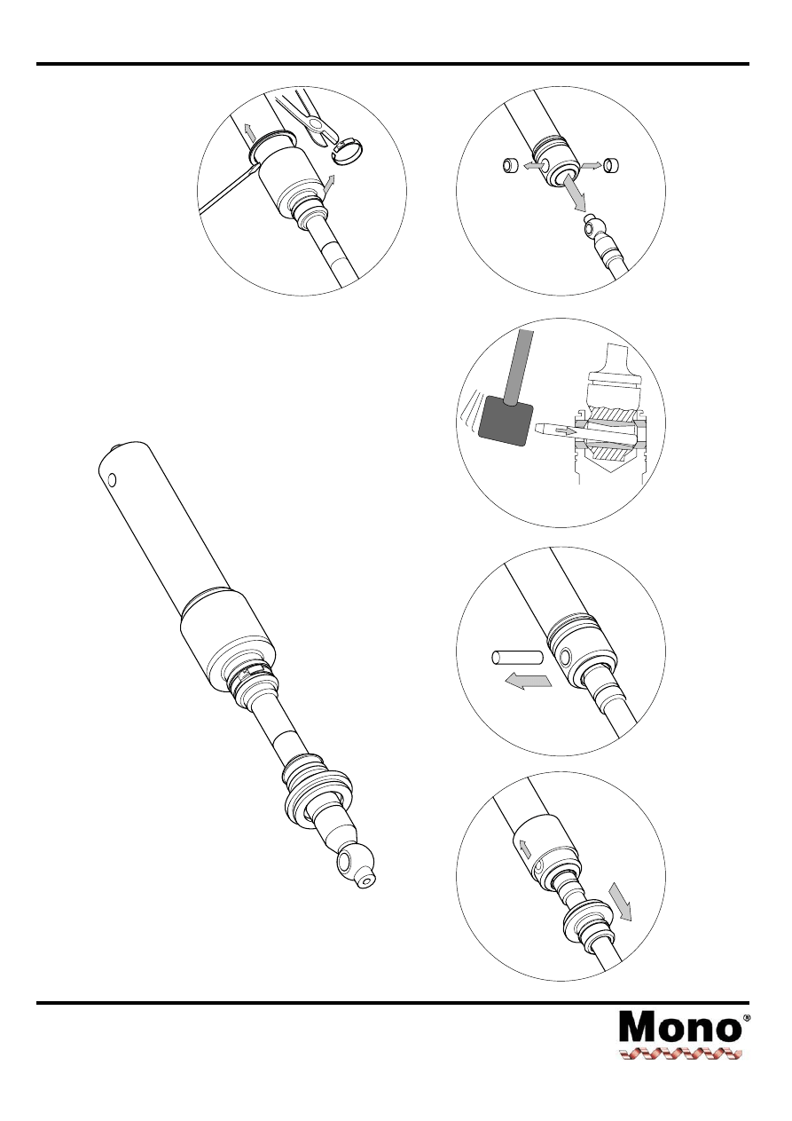
Dismantling & Assembly Diagrams
Section 4, Page 5
Issued - December 2000
5a
5c
5d
5e
5f
5b
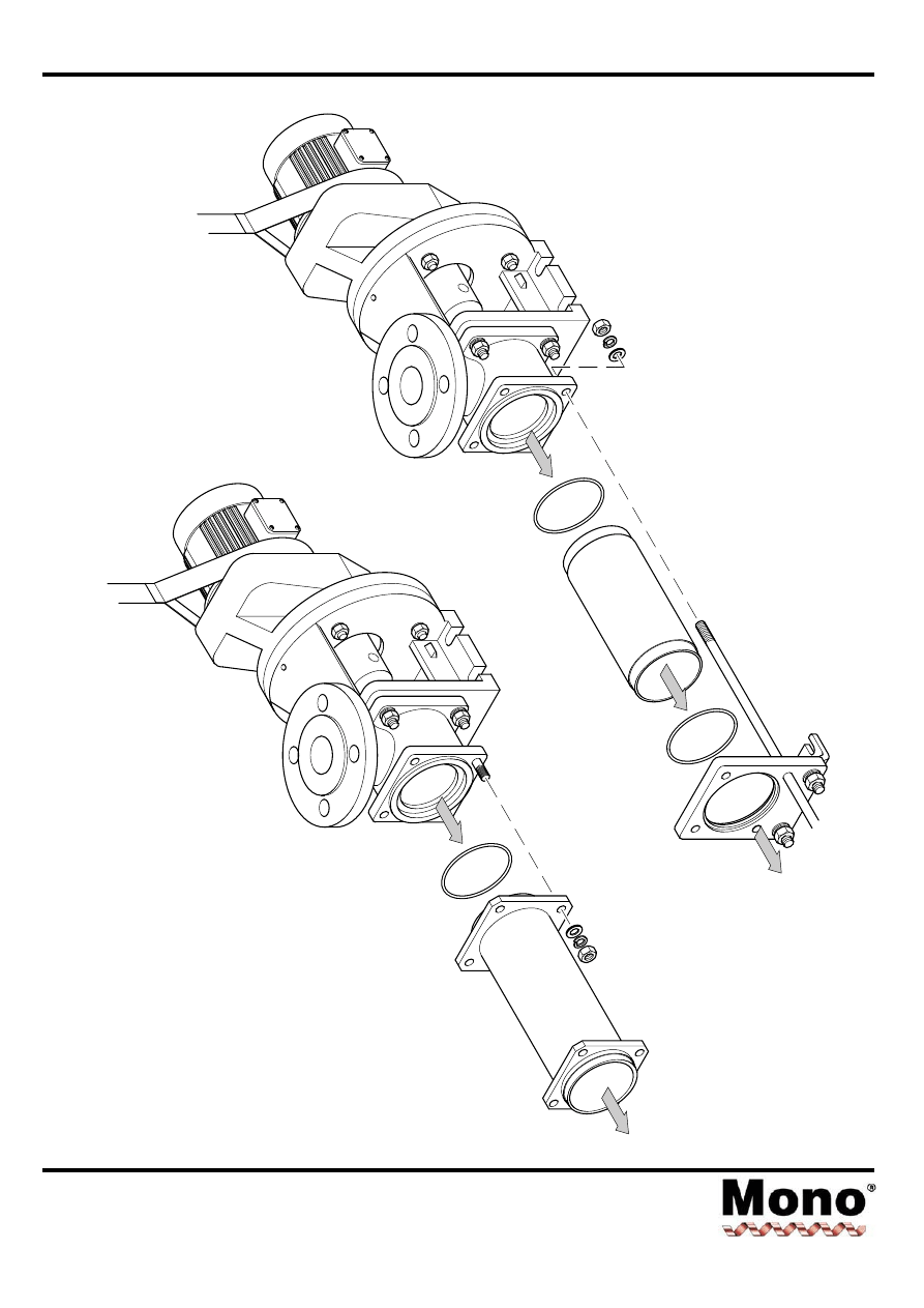
Dismantling & Assembly Diagrams
Section 4, Page 6
Issued - December 2000
OR
6
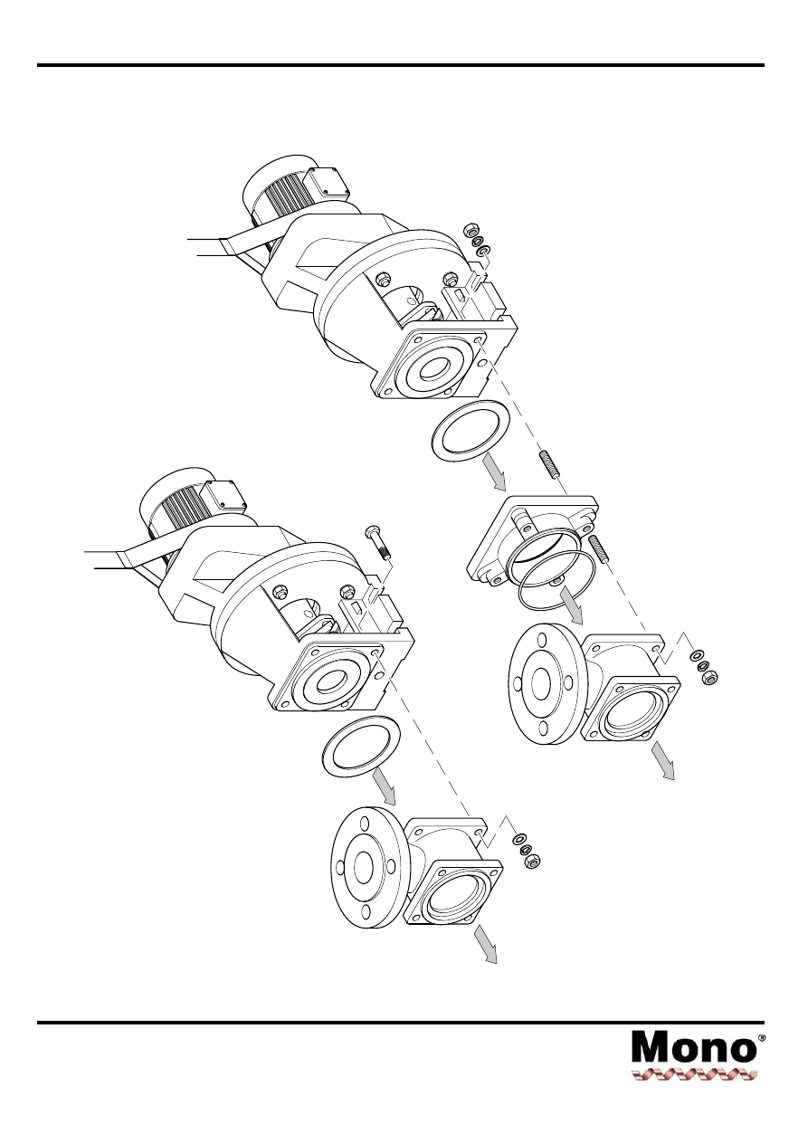
Dismantling & Assembly Diagrams
Section 4, Page 7
Issued - December 2000
OR
7
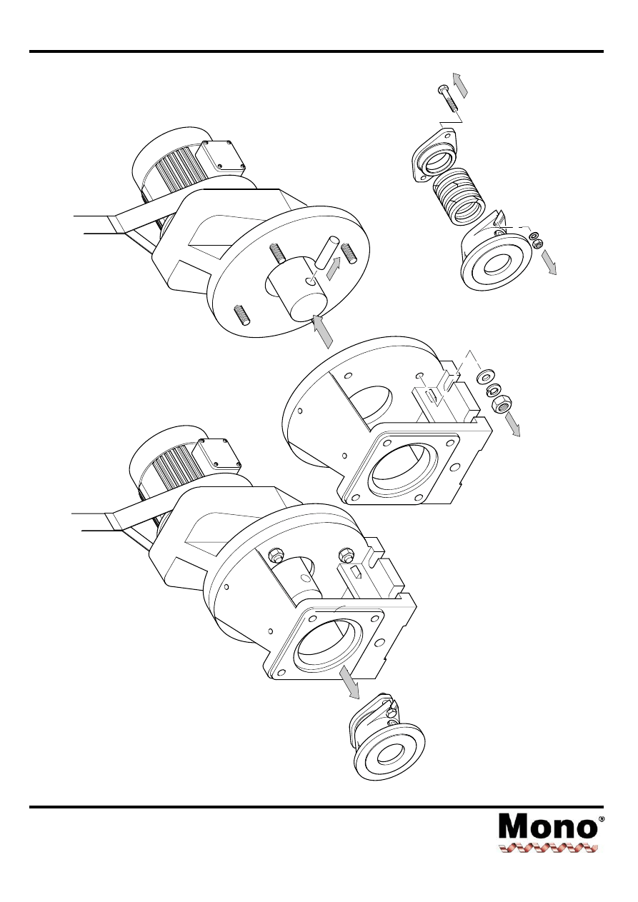
Dismantling & Assembly Diagrams
Section 4, Page 8
Issued - December 2000
8
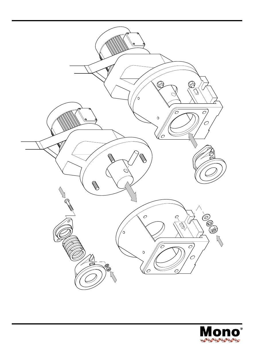
Dismantling & Assembly Diagrams
Section 4, Page 10
Issued - December 2000
ASSEMBLY
10
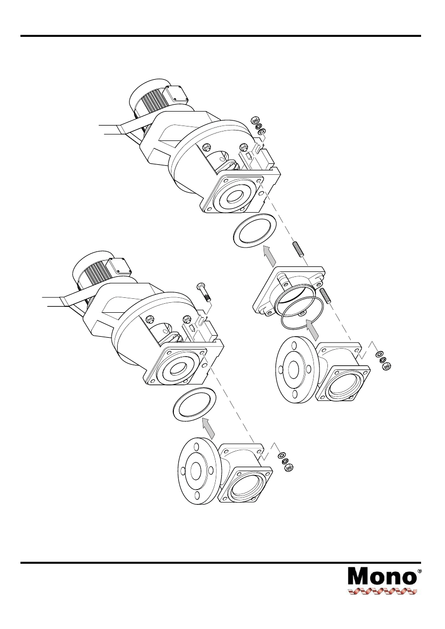
Dismantling & Assembly Diagrams
Section 4, Page 12
Issued - December 2000
OR
12
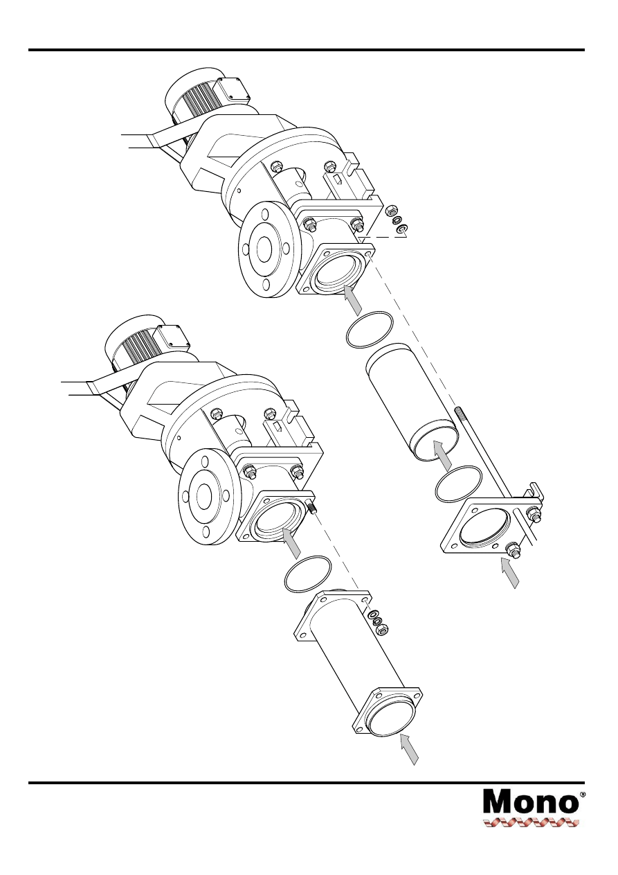
Dismantling & Assembly Diagrams
Section 4, Page 13
Issued - December 2000
OR
13
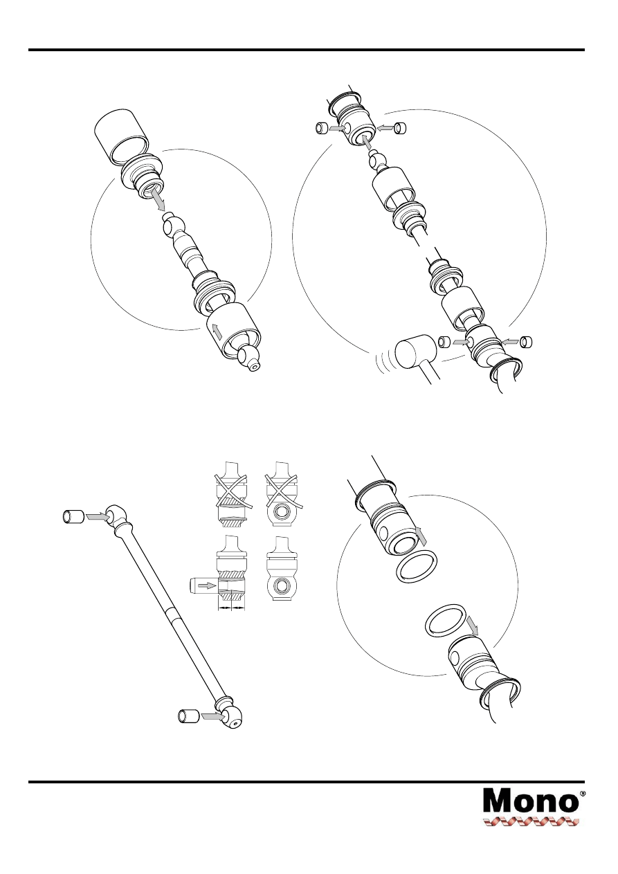
Dismantling & Assembly Diagrams
Section 4, Page 14
Issued - December 2000
14
15
16a
16b
=
=
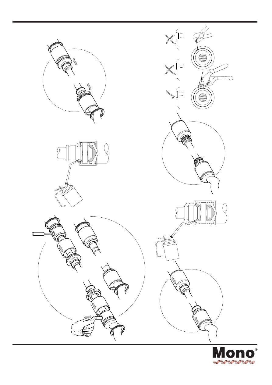
Dismantling & Assembly Diagrams
Section 4, Page 15
Issued - March 2002
17
19
20
21
22
18
Correct
tool
available
from
Mono
Part
Number:
80D1331
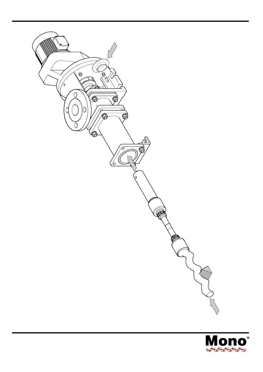
Dismantling & Assembly Diagrams
Section 4, Page 16
Issued - December 2000
23
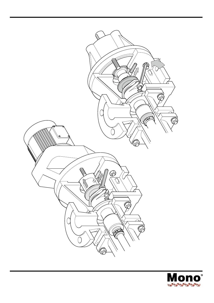
Dismantling & Assembly Diagrams
Section 4, Page 17
Issued - December 2000
24
OR
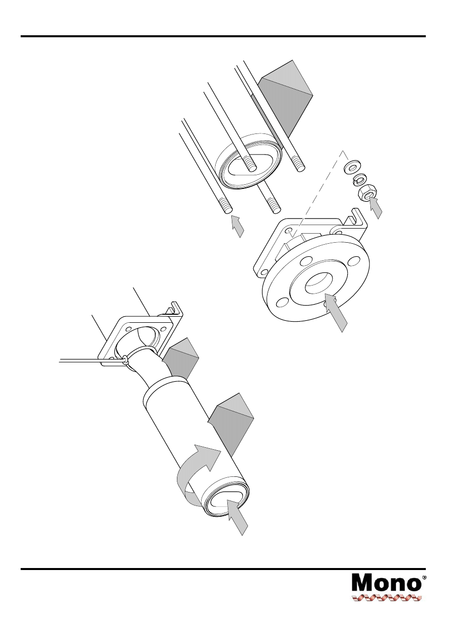
Dismantling & Assembly Diagrams
Section 4, Page 18
Issued - December 2000
25
26
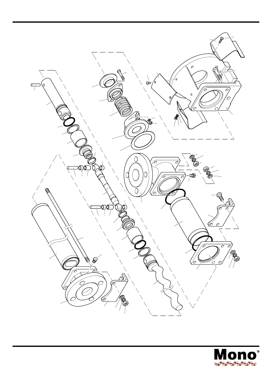
Exploded Views
Section 4, Page 19
Issued - December 2000
24A
62A
P503
P505
P504
22A
95A
P404
75B
29B
27D
27B
27D
26A
29A
27C
27A
27C
20B
P202
P203
10A
08A
65A
42A
P201
01A
P501
15A
P101
P109
P108
P102
25A
P402
P405
75A
28A
P406
28B
P104
P502
23A
'B' RANGE
B041,B04K,B042,B051,B05K
B052,B061,B06K,B062
62B
P515
P506
P508
P507
P516
P517
P518
23B
P510
P509
76A
P105
P107
P106
P103
06A/06B
P401
32A
29C
P403
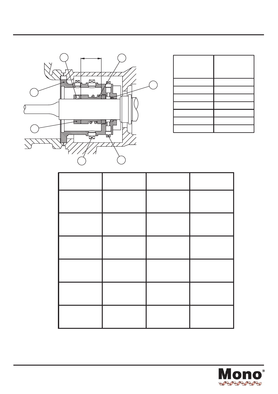
Setting Length - Mechanical Seal
Section 4, Page 22
Issued - November 2001
P201
P203
66A
65A
10A
P202
10B
Drawing
Identification
Number
Description
P201
P202
P203
10A
10B
65A
66A
¼" BSP Taper Plug
1
/
8
"
BSP Taper Plug
Grub Screw
Mechanical Seal
Lipseal (Optional)
Seal Housing
Abutment Ring
Pump Models
Seal Housing
Shaft Diameter
(mm)
Setting Length L
Crane 2100*
(mm)
B012 B014
B021 B022 B024
B03K B031 B032
B0XK B0X1
E012
32
26
B0X2
B04K B041 B042
B05K B051
B041
45
30
B052
B06K B061
B061
55
30
B062
B07K B071 B072
B08K B081
B071
65
33
B082
B09K B091 B092
B10K B101
B091
85
40
B102
B12K B121
E121
85
40
* For seals other than the Crane 2100 please refer to the manufacturer's instructions.
L
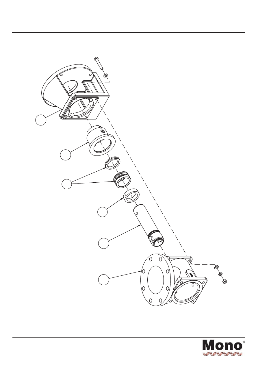
Exploded Views - Mechanical Seal
Section 4, Page 23
Issued - November 2001
23A
32A
65B
10B
65A
01A

Torque Tightening Figures
Section 5, Page 1
Issued - December 2000
PUMP SIZE
BODY/SUCT. CHAMBER
Nm
STATOR TIE BARS
Nm
P526
P105
P530
P506 P503
B041
11
11
B04K
11
11
B042
11
11
B051
11
11
B05K
21
11
B052
21
11
B061
21
24
B06K
21
24
B062
36
24
B071
36
24
B07K
36
24
B072
36
24
B081
36
40
B08K
36
40
B082
50
-
36
40
B091
90
75
B09K
90
75
B092
90
75
B101
90
75
B10K
90
75
B102
90
75
B121
176
120
B12K
176
120
Note: Torque tolerances are +/-5% of stated nominal figures.

Pin Joint Lubrication
Section 5, Page 2
Issued - January 2002
TABLE 1 - COUPLING ROD PIN JOINT LUBRICATION CHART
LUBRICATION
B041
B04K
B042
B051
B05K
B052
B061
B06K
B062
B071
B07K
B072
Kluber Syntheso
D460 EP oil
R
R
R
R
R
R
R
R
R
R
R
R
Mobil gear oil
SHC 320
SA
SA
SA
SA
SA
SA
SA
SA
SA
SA
SA
SA
Mobilith SHC 007
semi-fluid grease
SA
SA
SA
SA
SA
SA
SA
SA
-
-
-
-
Kluberoil 4UHI
460
F
F
F
F
F
F
F
F
F
F
F
F
Capacity Required
(in ml)
15
15
15
15
15
30
30
30
40
40
40
40
LUBRICATION
B081
B08K
B082
B091
B09K
B092
B101
B10K
B102
B121
B12K
Kluber Syntheso
D460 EP oil
R
R
R
R
R
R
R
R
R
R
R
Mobil gear oil
SHC 320
SA
SA
SA
SA
SA
SA
SA
SA
SA
SA
SA
Mobilith SHC 007
semi-fluid grease
-
-
-
-
-
-
-
-
-
-
Kluberoil 4UHI
460
F
F
F
F
F
F
F
F
F
F
F
Capacity Required
(in ml)
40
40
65
65
65
65
65
65
120
120
120
R
=
Not Recommended for Food Applications
SA
=
Not a Suitable Alternative for Food Applications
F
=
Recommended for Food Applications
RECOMMENDED SERVICE INTERVALS
1.
Inspect and lubricate every 3000 operating hours.
2.
If further advice is required relating to service intervals for specific arduous applications please contact Mono Pumps
Limited.

Mono Pumps Limited
Martin Street, Audenshaw
Manchester, M34 5DQ, England
Tel: +44 (0) 161 339 9000 Fax: +44 (0) 161 344 0727
E-mail: info@mono-pumps.com
www.mono-pumps.com
Issued - May 2001
Mono Pumps Around the World
A Halliburton Company
Contacts:
MONO PUMPS LIMITED
Martin Street
Audenshaw
Manchester
England
M34 5DQ
Tel: 0161 339 9000
Fax: 0161 344 0727
E-mail (general): info@mono-pumps.com
E-mail (service): service@mono-pumps.com
Web site: www.mono-pumps.com
MONO PUMPS (AUSTRALIA) PTY LTD
Mono House
338-348 Lower Dandenong Road
Mordialloc 3195
Victoria
Australia
Tel: +61 (0)3 9580 5211
Fax: +61 (0)3 9580 6659
E-mail: ozsales@mono-pumps.com
Web site: www.mono-pumps.com
MONOFLO, INC.
16503 Park Row
Houston
Texas 77084
USA
Tel: +1 281 599 4700
Fax: +1 281 599 4733
E-mail: inquire@monoflo.com
Web site: www.monoflo.com
MONO PUMPS (NEW ZEALAND) LTD
P.O. Box 71-021
34-41 Fremlin Place
Avondale
Auckland 7
New Zealand
Tel: +64 (0)9 829 0333
Fax: +64 (0)9 828 6480
E-mail: info@mono-pumps.co.nz
Web site: www.mono-pumps.com
Europe:
Austria
Belgium
Cyprus
Czech Republic
Denmark
Estonia
Finland
France
Germany
Greece
Hungary
Iceland
Italy
Malta
Netherlands
Norway
Poland
Portugal
Romania
Russia
Spain
Sweden
Switzerland
Australasia:
Queensland
Adelaide
Perth
Darwin
Sydney
Tasmania
Fiji
Hong Kong
Indonesia
Japan
Korea
Malaysia
New Caledonia
South Pacific
Pakistan
Papua New Guinea
Philippines
Taiwan
Singapore
Solomon Islands
Sri Lanka
Thailand
Vanuatu
Vietnam
Middle East:
Bahrain
Israel
Jordan
Kuwait
Beirut
Lebanon
Qatar
Saudi Arabia
Sultanate of Oman
Syria
Turkey
United Arab Emirates
Republic of Yemen
South America:
Argentina
Brazil
Chile
Colombia
Costa Rica
Guatemala
Peru
Venezuela
West Indies
Distributors
UK/Eire:
Dublin
Channel Islands
Glasgow
West Midlands
Somerset
London
Aberdeen
Rotherham
Gtr. Manchester
Cleveland

JOWA 3SEP OWS
OILY WATER SEPARATOR
Standard
K:\1-NYA K\1-JOWA PRODUKTER\3SEP\Manual
39/41
15.0 Oil Sensor Operating Manual
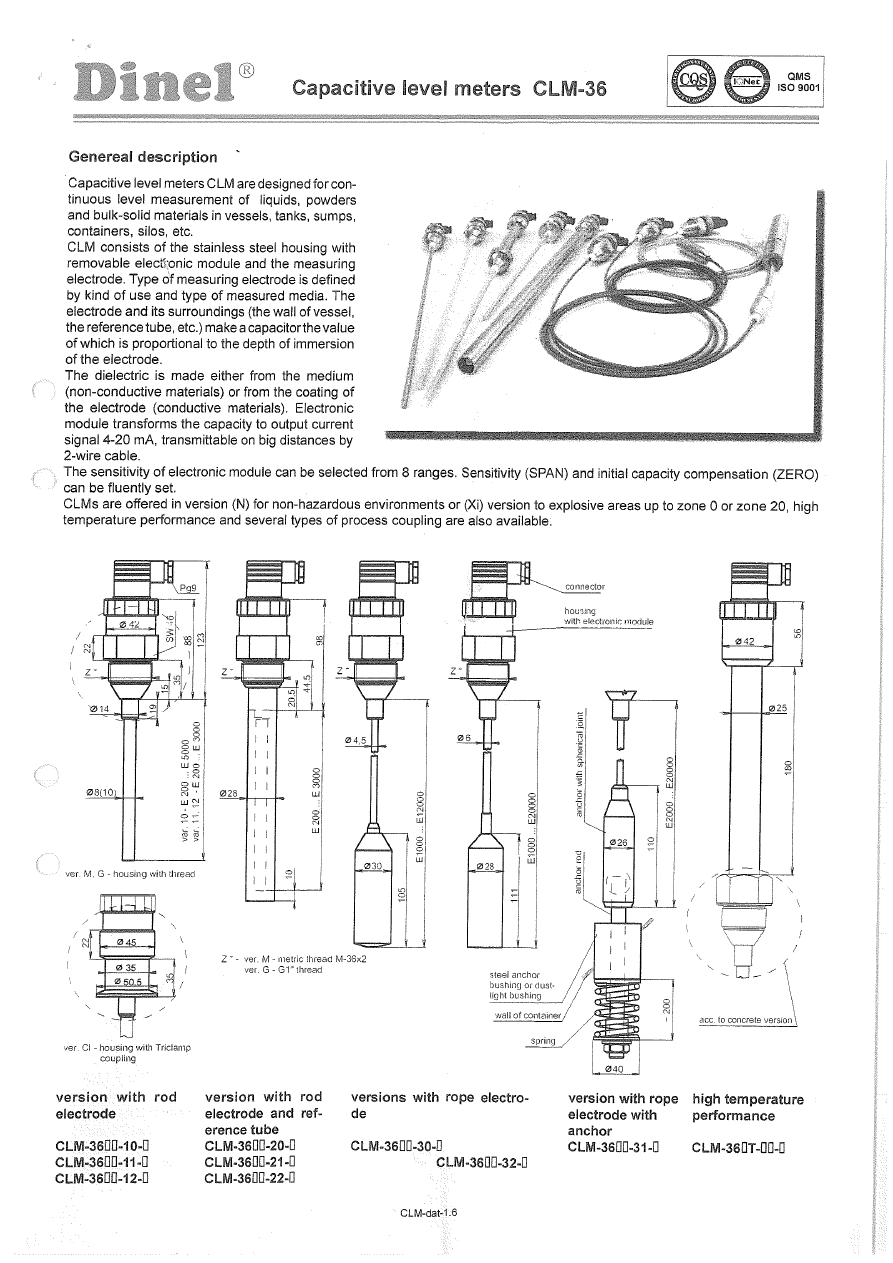
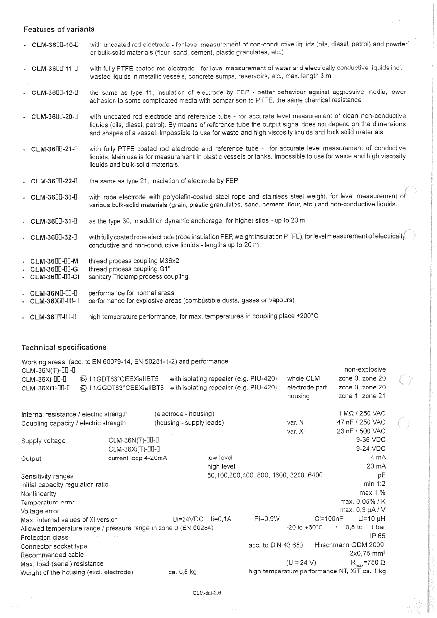
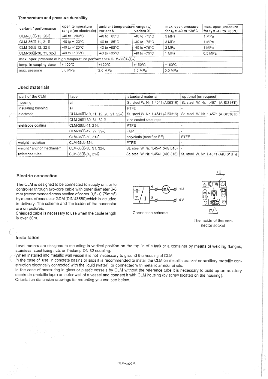
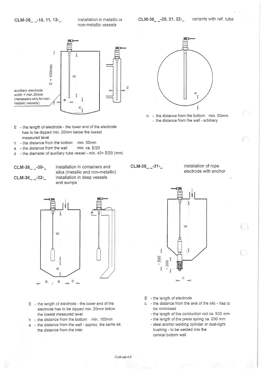
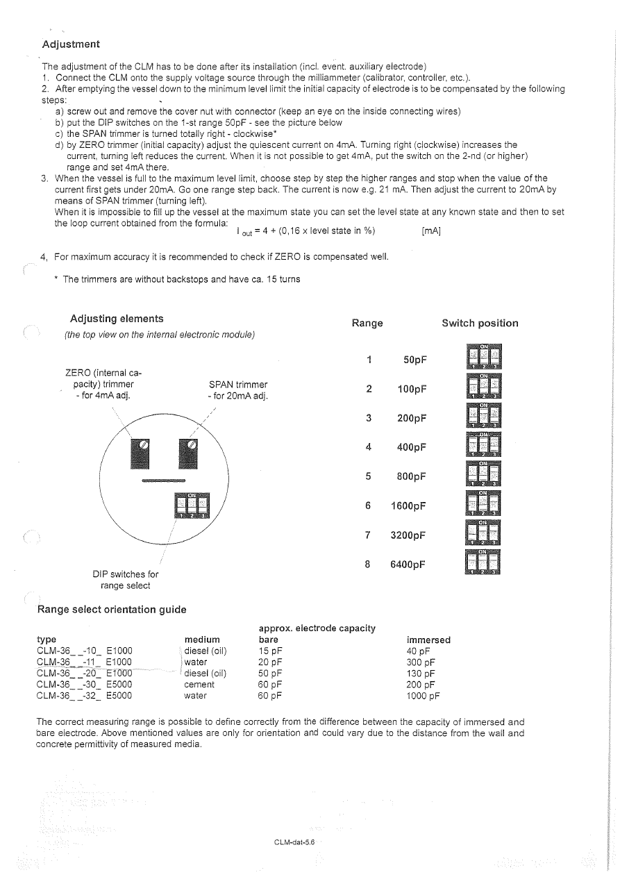
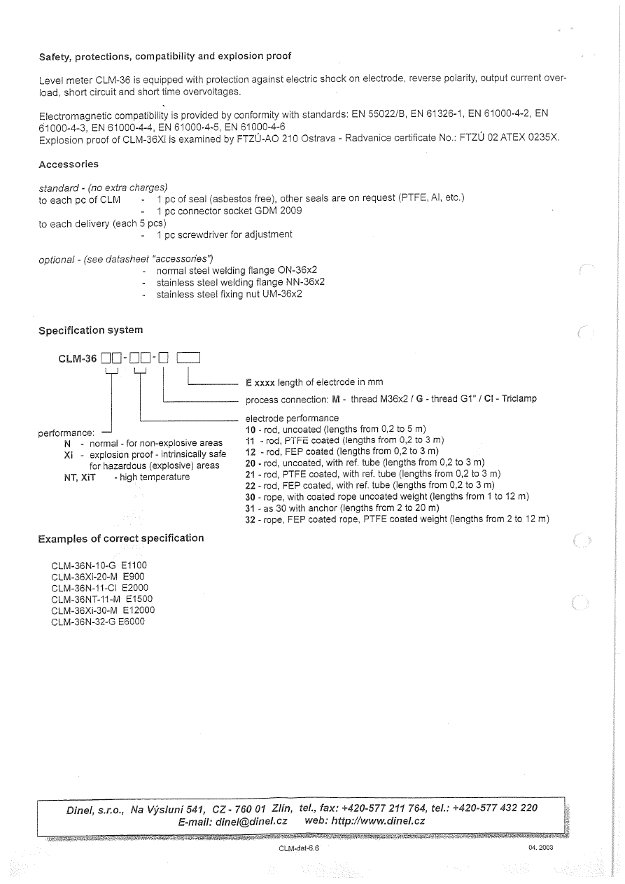
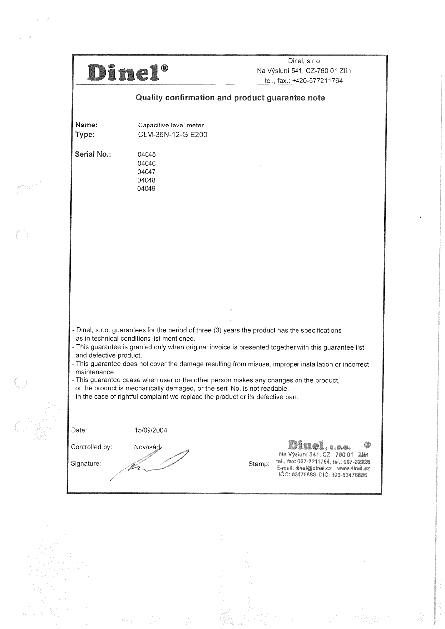

JOWA 3SEP OWS
OILY WATER SEPARATOR
Standard
K:\1-NYA K\1-JOWA PRODUKTER\3SEP\Manual
40/41
16.0 Spare/ Consumables Parts List

JOWA 3SEP OWS Spares Rev D
Recommended Consumables and Spareparts for
JOWA 3SEP OWS 1.0m3/h
Quantity for:
Item
Article No
Description
1 year
3 years
(not supplied)
01:00 COMSUMABLES:
01:01 17004-12407
Jowa F-200C Filter material
50
100
01:02 24013-70800
Zinc Anode 1-5m3 Filter Tanks
2
01:03 20013-02500
Zinc Anode Gravity Tank
1
02:00 SPAREPARTS:
02:01 50075-21002
Filterscreen top 1.0mm
2
02:02 50075-22002
Filterscreen bottom 0.5mm
2
02:03 50100-21002
Filterscreen Drain 0.5mm
2
02:04 22311-03600
Oil Sensor Stick CLM-36N
1
02:05 10109-00002
Pressure gauge 0-10 BAR P1
02:06 94007-52010
Fuse 1 A
10
10
02:07 27060-20202
Main Switch KG20
02:08 27060-42001
Power On CG4 A1787
02:09 27060-42102
1-0-2 Switch CG4 A210
02:10 20610-01042
Reset Push Button
02:11 20600-00110
OPLC M91-2-R1
02:12 20600-00111
Epander PLC EX90-D18-R08
02:13 42000-00230
Relay PT370730
02:14 99100-00203
Relay 3RT1017 1AP01 5,5kW
02:15 99100-00018
Terminals WDU 2,5
02:16 20700-75552
Transformer 380-480/2X110
02:17 99100-00086
Transformer 230VAC/24V DC
03:00 RTE OIL CONTENT METER
03:01 87081-00000
JOWA RTE Oil Content Meter
03:02 87082-00000
Bilge Alarm Deckma
04:00 PUMP
04:01 23001-00012
Stator Mono Cgg
04:02 22415-00002
O ring mono pump G range
04:03 22415-00001
Mechanical Seal
08:00 VALVES
08:01 22304-00256
Pneumatic valves DN25
08:02 22304-00326
Pnematic valves DN32
08:03 22304-00406
Pnematic valves DN40
08:04 22304-06236
Solenoid valves complete
08:05 22303-20224
Safety valve DN20 4 BAR
08:06 10107-08436
Pressure Gauge Valve DN15
K:\1-NYA K\1.2-JOWA PRODUKTER\3SEP\Manual\Documents\Spare Parts List\

JOWA 3SEP OWS Spares Rev D
Recommended Consumables and Spareparts for
JOWA 3SEP OWS 2.5m3/h
Item
Article No
Description
Start Up
1 year 3 years
(not supplied)
01:00 COMSUMABLES:
01:01 17004-12407
Jowa F-200C Filter material
100
200 kg
01:02 20013-70800
Zinc Anode 1-5m3 Filter Tanks
2
01:03 20013-02500
Zinc Anode Gravity Tank
1
1
02:00 SPAREPARTS:
02:01 50150-20002
Filterscreen top 1.0mm
4
02:02 50150-20001
Filterscreen bottom 0.5mm
4
02:03 50100-22002
Filterscreen Drain 0.5mm
2
02:04 22311-03600
Oil Sensor Stick CLM-36N
1
02:05 10109-00002
Pressure gauge 0-10 BAR P1
02:06 94007-52010
Fuse 1 A
10
10
02:07 27060-20202
Main Switch KG20
02:08 27060-42001
Power On CG4 A1787
02:09 27060-42102
1-0-2 Switch CG4 A210
02:10 20610-01042
Reset Push Button
02:11 20600-00110
OPLC M91-2-R1
02:12 20600-00111
Epander PLC EX90-D18-R08
02:13 42000-00230
Relay PT370730
02:14 99100-00203
Relay 3RT1017 1AP01 5,5kW
02:15 99100-00018
Terminals WDU 2,5
02:16 20700-75552
Transformer 380-480/2X110
02:17 99100-00086
Transformer 230VAC/24V DC
03:00 RTE OIL CONTENT METER
03:01 87081-00000
JOWA RTE Oil Content Meter
03:02 87082-00000
Bilge Alarm Deckma
04:00 PUMP
04:01 23002-00012
Stator Mono Cgh
1
04:02 22415-00002
O ring mono pump G range
1
04:03 22415-00001
Mechanical Seal
1
08:00 VALVES
08:01 22304-00256
Pneumatic valves DN25
08:02 22304-00326
Pnematic valves DN32
08:03 22304-00406
Pnematic valves DN40
08:04 22304-06236
Solenoid valves complete
1
08:05 22303-20224
Safety valve DN20 4 BAR
08:06 10107-08436
Pressure Gauge Valve DN15
Quantity for:
K:\1-NYA K\1.2-JOWA PRODUKTER\3SEP\Manual\Documents\Spare Parts List\

JOWA 3SEP OWS Spares Rev D
Recommended Consumables and Spareparts for
JOWA 3SEP OWS 5.0m3/h
Item
Article No
Description
Start Up
1 year 3 years
(not supplied)
01:00 COMSUMABLES:
01:01 17004-12407
Jowa F-200C Filter material
200
400 kg
01:02 24013-70800
Zinc Anode 1-5m3 Filter Tanks
2
2
01:03 20013-02500
Zinc Anode Gravity Tank
1
1
02:00 SPAREPARTS:
02:01 50300-20002
Filterscreen top 1.0mm
4
02:02 50300-20001
Filterscreen bottom 0.5mm
4
02:03 50100-23002
Filterscreen Drain 0.5mm
2
02:04 22311-03600
Oil Sensor Stick CLM-36N
1
02:05 10109-00002
Pressure gauge 0-10 BAR P1
02:06 94007-52010
Fuse 1 A
10
10
02:07 27060-20202
Main Switch KG20
02:08 27060-42001
Power On CG4 A1787
02:09 27060-42102
1-0-2 Switch CG4 A210
02:10 20610-01042
Reset Push Button
02:11 20600-00110
OPLC M91-2-R1
02:12 20600-00111
Epander PLC EX90-D18-R08
02:13 42000-00230
Relay PT370730
02:14 99100-00203
Relay 3RT1017 1AP01 5,5kW
02:15 99100-00018
Terminals WDU 2,5
02:16 20700-75552
Transformer 380-480/2X110
02:17 99100-00086
Transformer 230VAC/24V DC
03:00 RTE OIL CONTENT METER
03:01 87081-00000
JOWA RTE Oil Content Meter
03:02 87082-00000
Bilge Alarm Deckma
04:00 PUMP
04:01 24219-05010
Stator 1
04:02 24219-05011
Rotor
1
04:03 24219-05012
Mechanical Seal
1
04:04 24219-05013
Coupling
1
08:00 VALVES
08:01 22304-00256
Pneumatic valves DN25
08:02 22304-00326
Pnematic valves DN32
08:03 22304-00406
Pnematic valves DN40
08:04 22304-06236
Solenoid valves complete
1
08:05 22303-25324
Safety valve DN25 4 BAR
08:06 10107-08436
Pressure Gauge Valve DN15
Quantity for:
K:\1-NYA K\1.2-JOWA PRODUKTER\3SEP\Manual\Documents\Spare Parts List\

JOWA 3SEP OWS Spares Rev D
Recommended Consumables and Spareparts for
JOWA 3SEP OWS 10.0m3/h
Item
Article No
Description
Start Up
1 year 3 years
(not supplied)
01:00 COMSUMABLES:
01:01 17004-12407
Jowa F-200C Filter material
500
1000 kg
01:02 24013-70130
Zinc Anode 10m3 Filter Tanks
2
01:03 20013-02500
Zinc Anode Gravity Tank
1
02:00 SPAREPARTS:
02:01 50750-20002
Filterscreen top 1.0mm
6
02:02 50750-20001
Filterscreen bottom 0.5mm
6
02:03 50100-24012
Filterscreen Drain 0.5mm
4
02:04 22311-03600
Oil Sensor Stick CLM-36N
1
02:05 10109-00002
Pressure gauge 0-10 BAR P1
02:06 94007-52010
Fuse 1 A
10
10
02:07 27060-20202
Main Switch KG20
02:08 27060-42001
Power On CG4 A1787
02:09 27060-42102
1-0-2 Switch CG4 A210
02:10 20610-01042
Reset Push Button
02:11 20600-00110
OPLC M91-2-R1
02:12 20600-00111
Epander PLC EX90-D18-R08
02:13 42000-00230
Relay PT370730
02:14 99100-00203
Relay 3RT1017 1AP01 5,5kW
02:15 99100-00018
Terminals WDU 2,5
02:16 20700-75552
Transformer 380-480/2X110
02:17 99100-00086
Transformer 230VAC/24V DC
03:00 RTE OIL CONTENT METER
03:01 87081-00000
JOWA RTE Oil Content Meter
03:02 87082-00000
Bilge Alarm Deckma
04:00 PUMP
04:01 24219-10010
Stator 1
04:02 24219-10011
Rotor
1
04:03 24219-10012
Mechanical Seal
1
04:04 24219-10013
Coupling
1
04:05 24219-10014
Coupling Kit
1
08:00 VALVES
08:01 22304-00256
Pneumatic valves DN25
08:02 22304-00326
Pnematic valves DN32
08:03 22304-00406
Pnematic valves DN40
08:04 22304-06236
Solenoid valves complete
1
08:05 22303-32404
Safety valve DN32 4 BAR
08:06 10107-08436
Pressure Gauge Valve DN15
Quantity for:
K:\1-NYA K\1.2-JOWA PRODUKTER\3SEP\Manual\Documents\Spare Parts List\

JOWA 3SEP OWS
OILY WATER SEPARATOR
Standard
K:\1-NYA K\1-JOWA PRODUKTER\3SEP\Manual
41/41
17.0 Approval Certificates
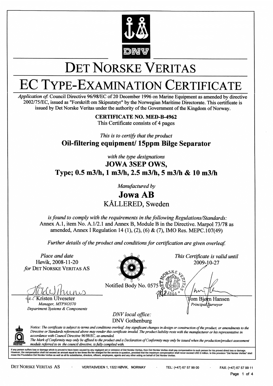
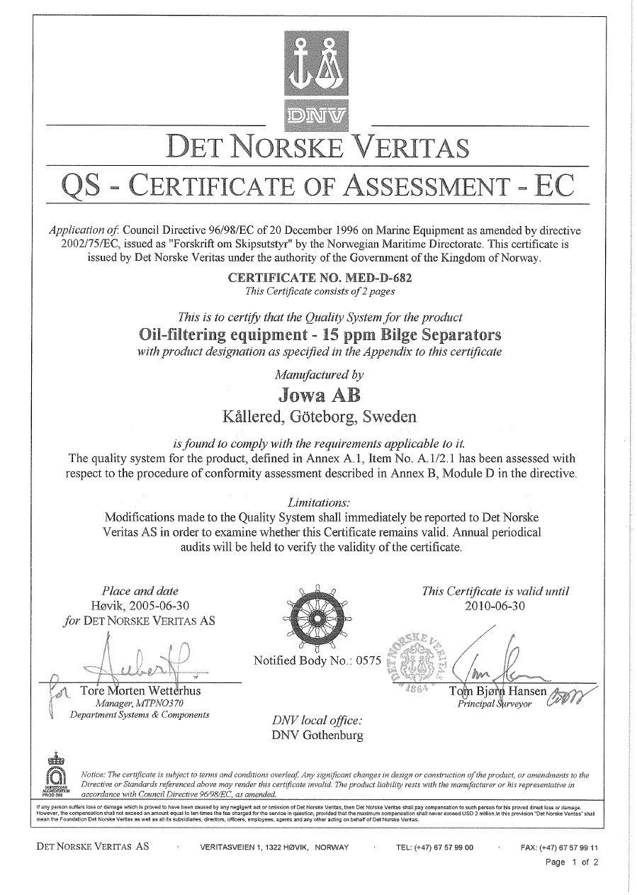
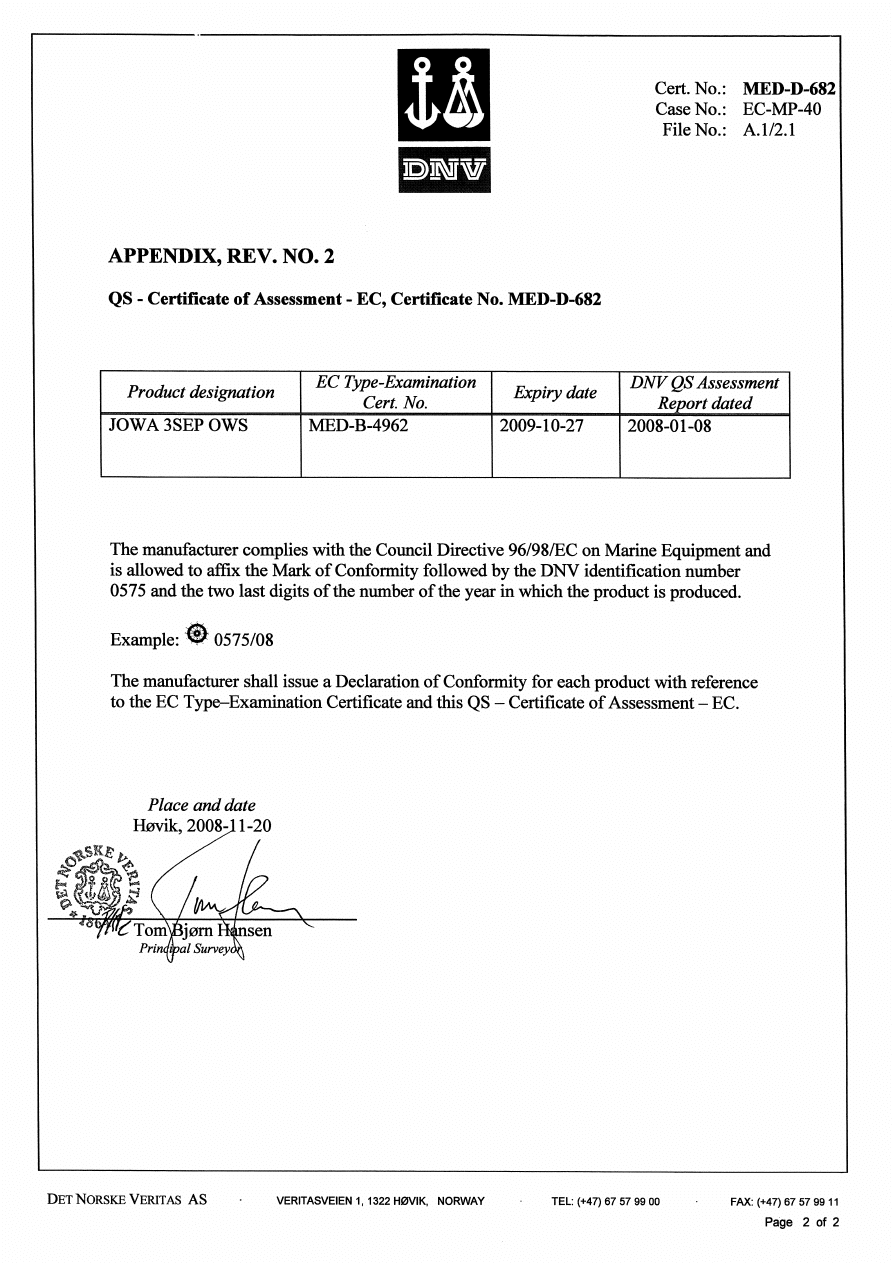
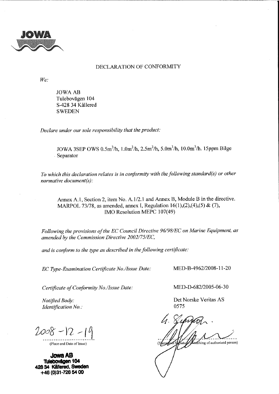
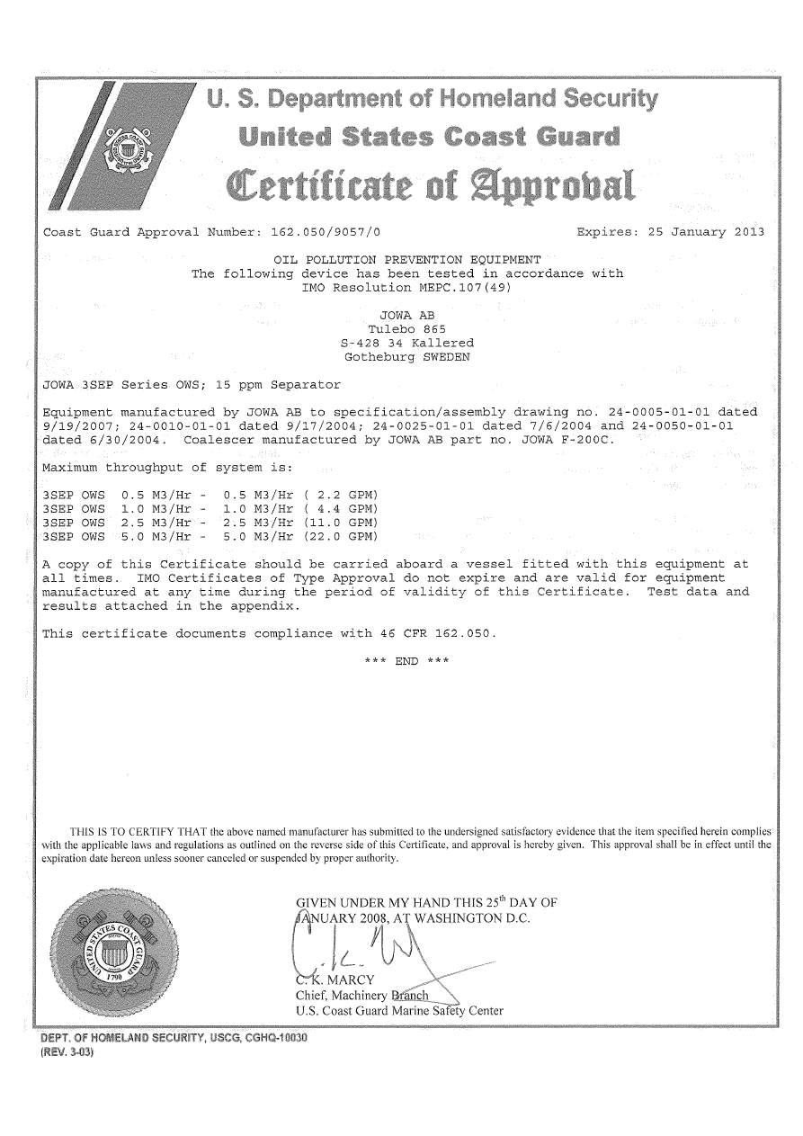
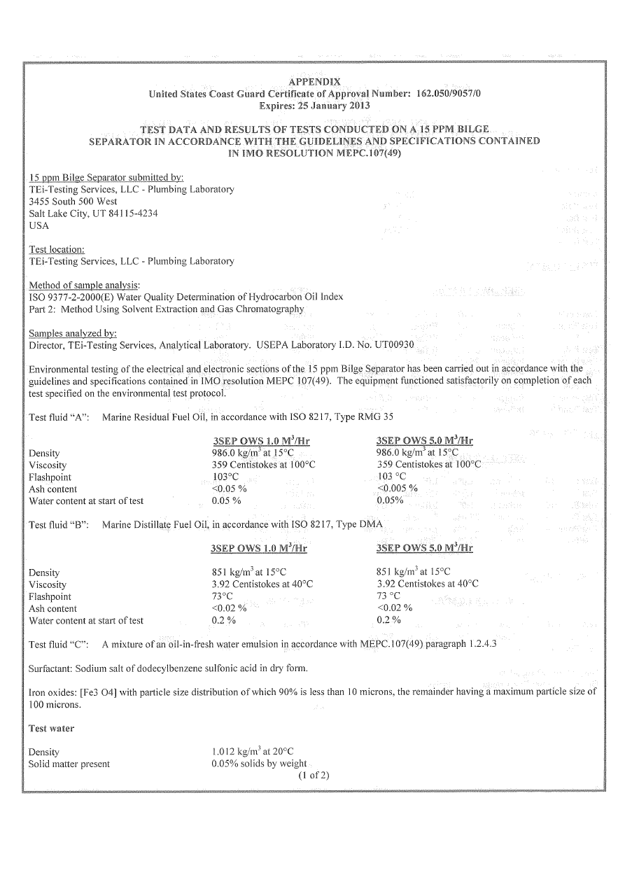

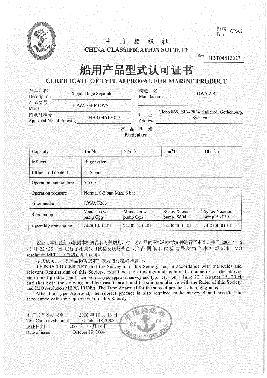
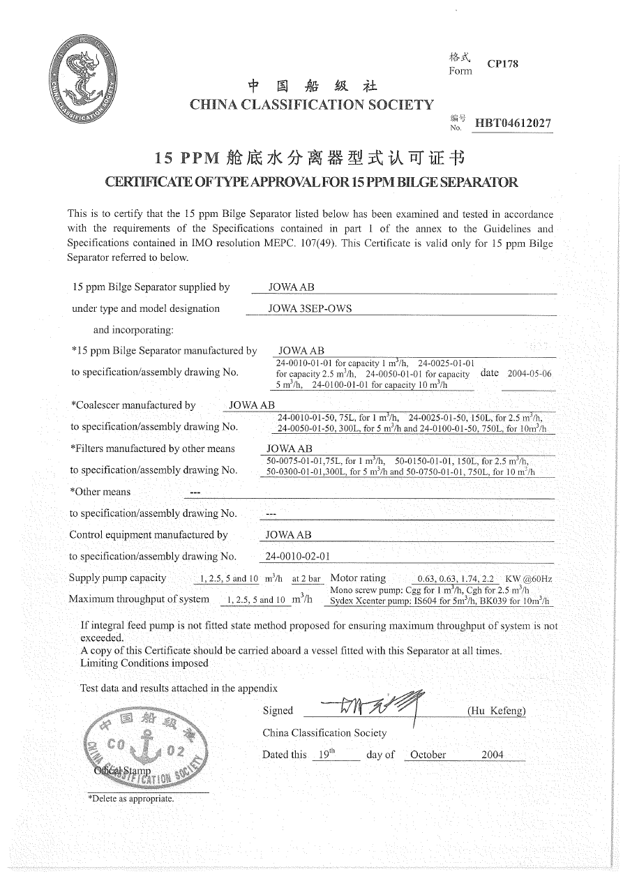
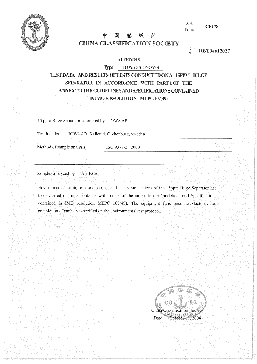

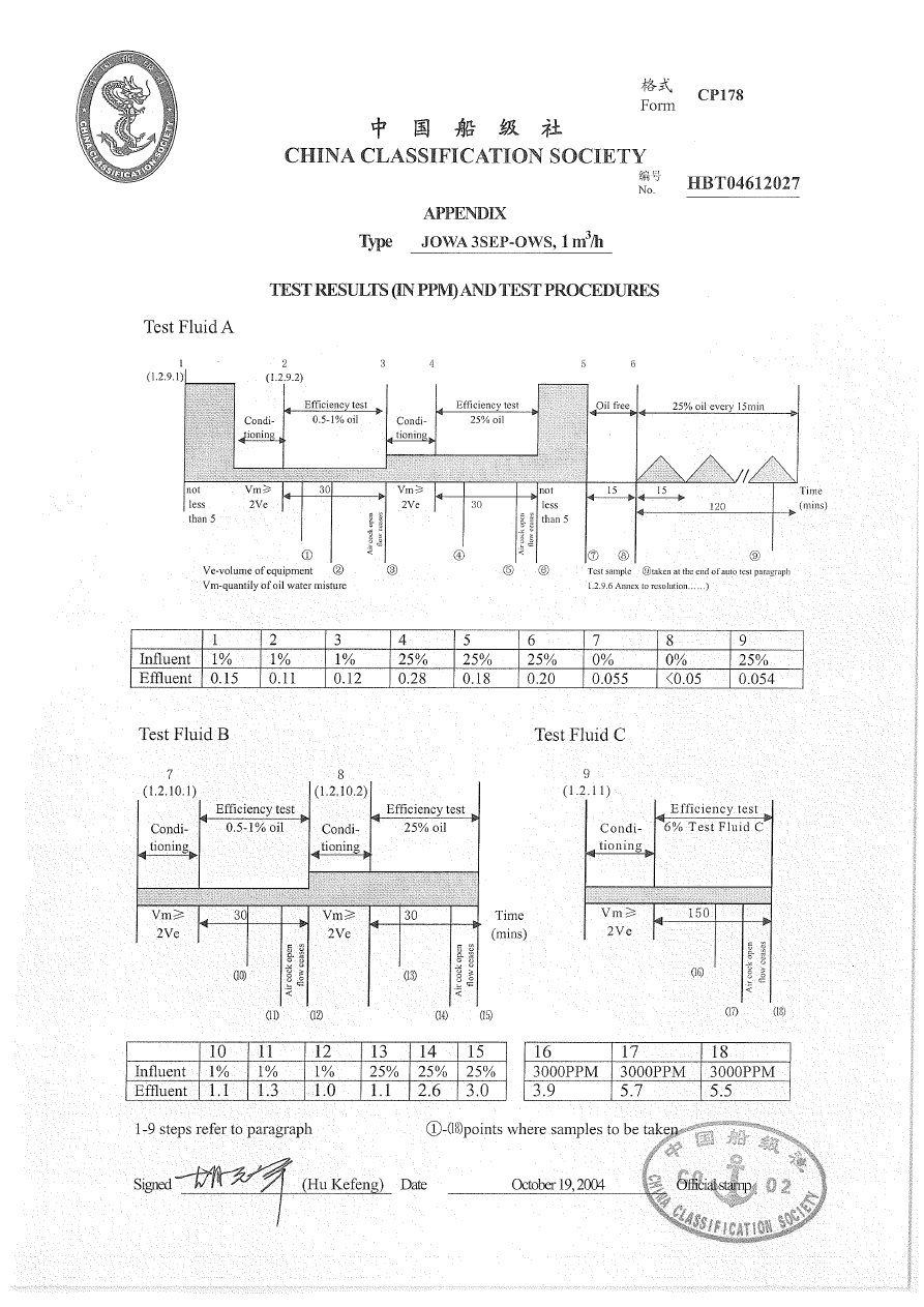
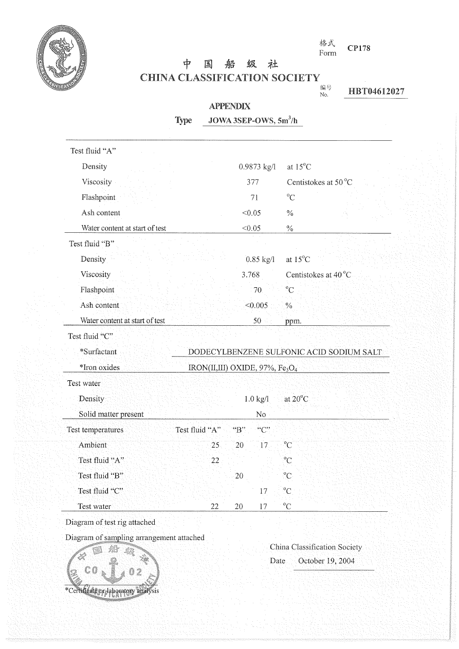
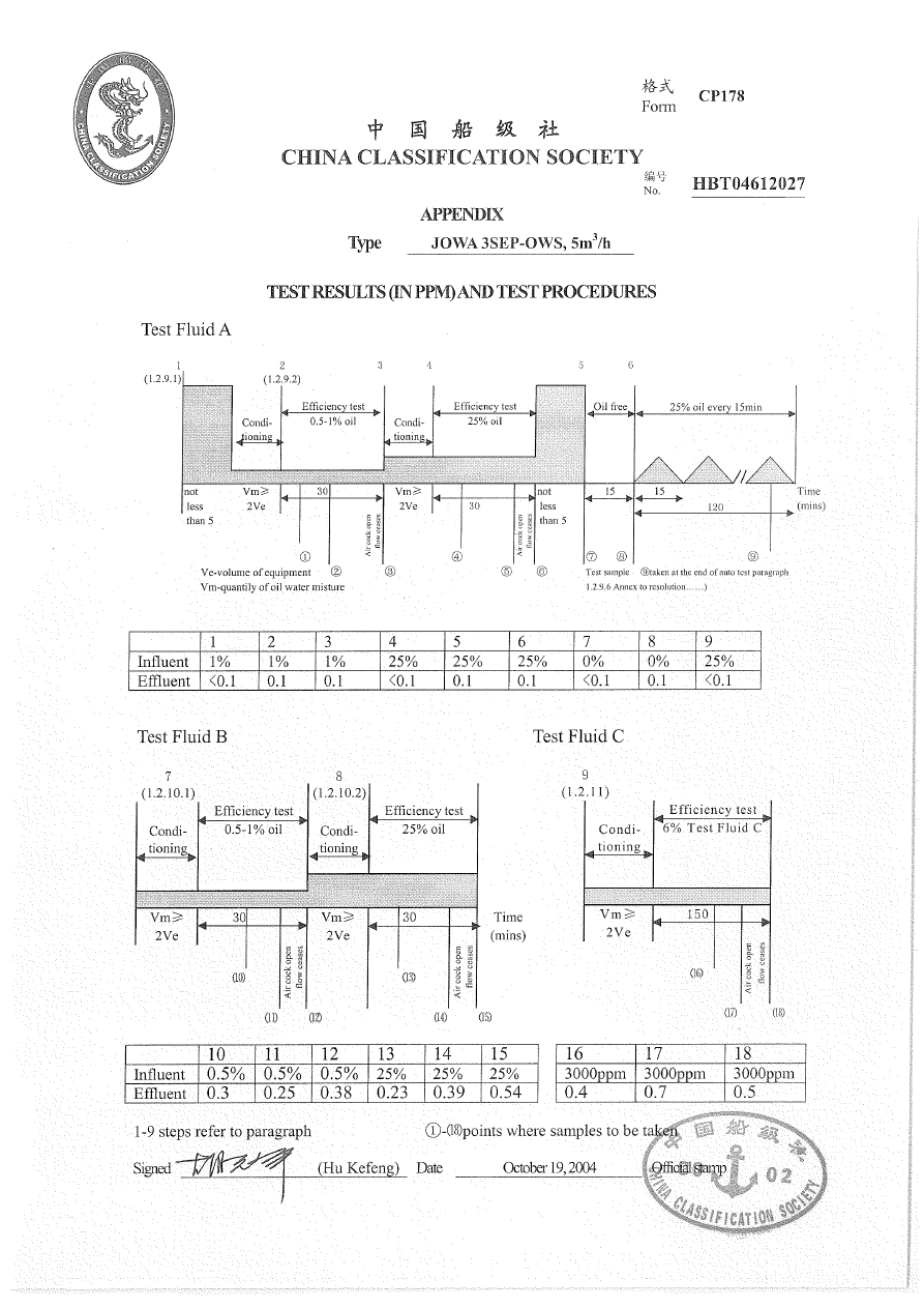

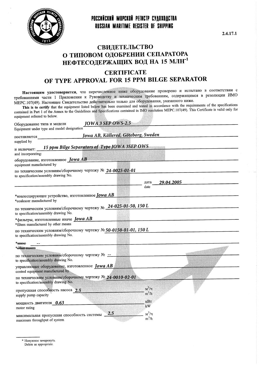
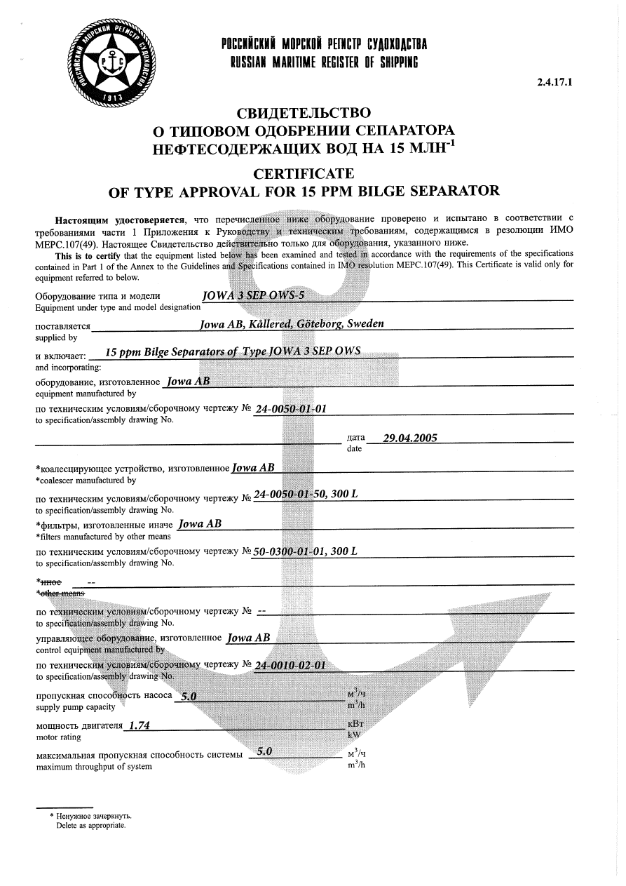
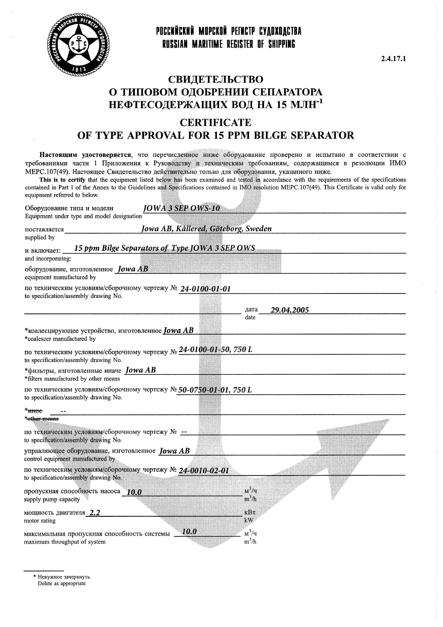
Wyszukiwarka
Podobne podstrony:
JOWA 3 SEP OWS Pump Mono
JOWA 3 SEP OWS Manual + deckmaRev Oil content meter 2
JOWA 3 SEP OWS Manual
JOWA 3 SEP OWS Manual + deckmaRev Oil content meter
Jowa OWS 15ppm bilge alarm new
JOWA OWS Diagram
Jowa OWS 15ppm bilge alarm new 15
Jowa OWS 15ppm bilge alarm new
Jowa OWS 15ppm bilge alarm new
398688 [crosti ru] mono
Dz.U.02.75.690, Elektrotechnika, SEP, Normy, rozporządzenia i inne bajki
SPRĘARKI, energetyka, mgr 2, sep, Grupa II
235772 [crosti ru] mono
więcej podobnych podstron