Date:
Rev:
Sign:
2007-09-07
6. 080616
GS/jim
JOWA SEAGUARD
15ppm Bilge Alarm
K:\1-NYA K\1.2-JOWA PRODUKTER\JOWA 15PPM Bilge Alarm\Manual
1
JOWA 15ppm Bilge Alarm
JOWA SEAGUARD
OPERATING INSTRUCTIONS AND
TECHNICAL MANUAL

Date:
Rev:
Sign:
2007-09-07
6. 080616
GS/jim
JOWA SEAGUARD
15ppm Bilge Alarm
K:\1-NYA K\1.2-JOWA PRODUKTER\JOWA 15PPM Bilge Alarm\Manual
2
Table of Contents
1.0
Introduction and general description .................................................. 4
1.1 General ............................................................................................................. 5
1.2
Guarantee and service...................................................................................... 5
1.3
Note on recycling. ............................................................................................ 5
2.0
Technical Specification......................................................................... 6
2 Specifications ................................................................................................ 7
2.1 Technical data JOWA SEAGUARD...................................................................... 7
3.0
Installation.............................................................................................. 8
3.1 Delivery ............................................................................................................ 8
3.2
Placement of the skid........................................................................................ 8
3.3 Pipe
Connections .............................................................................................. 8
3.4 Electric
Connections......................................................................................... 8
3.5
Adjusting the back pressure / flow in the sensor.............................................. 9
4.0
System Function Description. ............................................................ 10
4.1 Basic Functions .............................................................................................. 10
4.2 Alarms ............................................................................................................ 10
4.3 Logged
Data ................................................................................................... 10
4.3.1
Format of the log names ......................................................................... 11
4.3.2
Format of the logged data....................................................................... 11
4.3.3 Auto
flush ............................................................................................... 11
5.0
The Menu System ................................................................................ 12
5.1
General Overview of the Menu tree ............................................................... 12
5.2
Navigating the menus ..................................................................................... 13
5.3 Pages in the menu system.............................................................................. 13
5.3.1 Main Page.................................................................................................. 13
5.3.2 Service
Menu...................................................................................... 13
5.3.3 Clean sensor........................................................................................... 14
5.3.4. Signals .................................................................................................. 14
5.3.5 Simulation........................................................................................... 15
5.3.6 Password Protected................................................................................ 16
5.3.7 Settings Menu............................................................................................ 17
5.3.8 Valve/Alarm1/Alarm2........................................................................... 17
5.3.9 Auto flush .............................................................................................. 17
5.3.10
Log Menu .......................................................................................... 18
5.3.11 List log files........................................................................................ 18
5.3.12 Log
files.............................................................................................. 18
5.3.13
Print log on printer/RS232............................................................. 19
5.3.14 Alarm list ................................................................................................ 20
5.3.15 Information Menu................................................................................... 21
5.3.16 Control Unit........................................................................................ 21
5.3.17 Sensor Unit ......................................................................................... 21

Date:
Rev:
Sign:
2007-09-07
6. 080616
GS/jim
JOWA SEAGUARD
15ppm Bilge Alarm
K:\1-NYA K\1.2-JOWA PRODUKTER\JOWA 15PPM Bilge Alarm\Manual
3
5.3.18 JOWA info.............................................................................................. 21
6.0
Maintenance ......................................................................................... 22
7.0
Trouble Shooting ................................................................................. 23
8.0
Flow Diagram (P & I)............................................................................ 26
9.0
Mechanical Drawings .......................................................................... 27
10.0
Electrical drawings.............................................................................. 28
11.0
Spare Parts List ................................................................................... 29
12.0
Approval Certificates........................................................................... 31

Date:
Rev:
Sign:
2007-09-07
6. 080616
GS/jim
JOWA SEAGUARD
15ppm Bilge Alarm
K:\1-NYA K\1.2-JOWA PRODUKTER\JOWA 15PPM Bilge Alarm\Manual
4
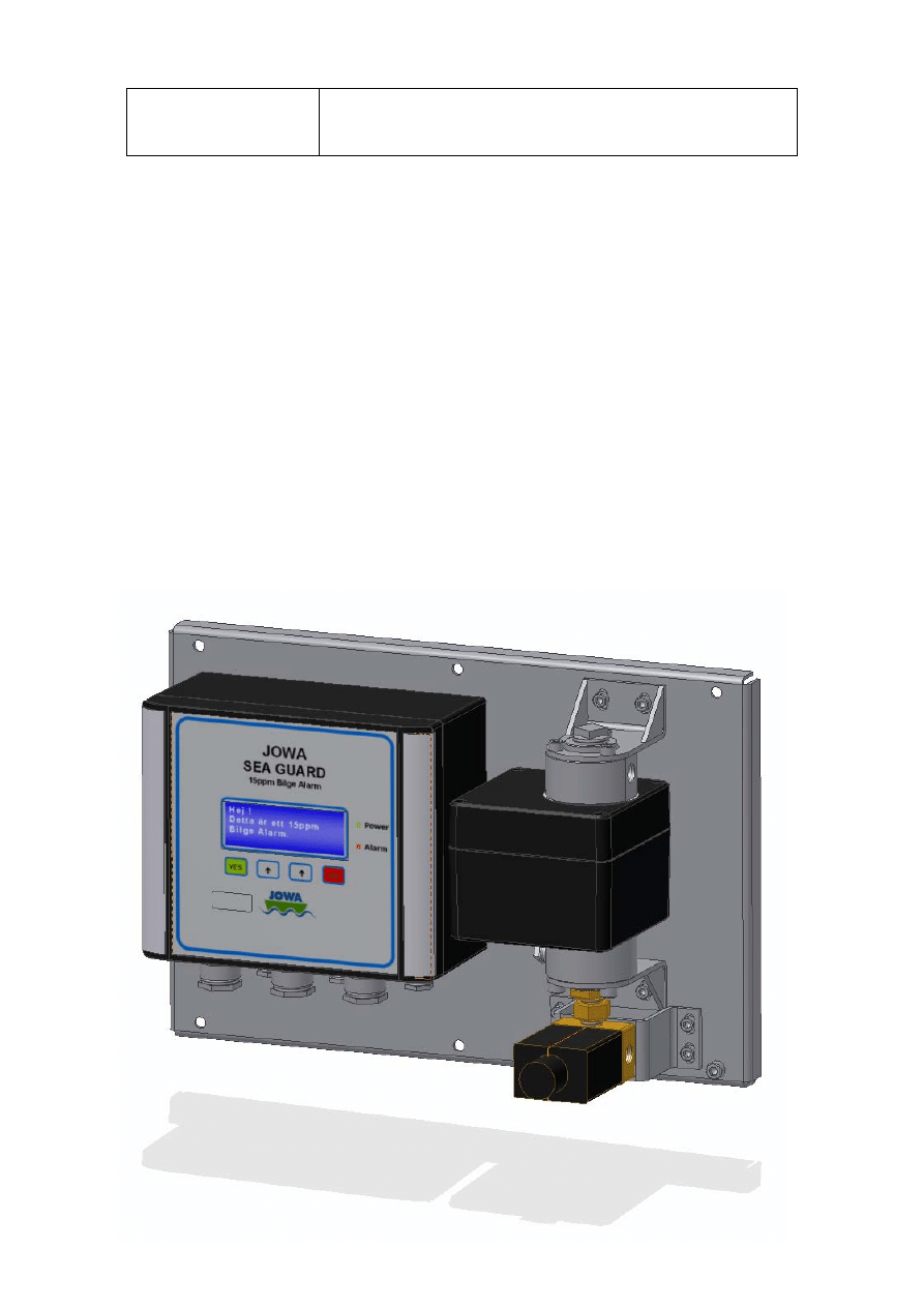
1.0 Introduction and general description
The JOWA SEAGUARD 15ppm Bilge alarm is designed to monitor the effluent
from a bilge water separator. The alarm is approved to IMO MEPC 107(49).
There are 2 alarm out signals which are triggered by the ppm oil content of the
separators effluent.
The JOWA SEAGUARD has a cleaning function, auto flush, designed to keep
the sensor as clean as possible. Auto flush occurs automatically.
The JOWA SEAGUARD log is controlled by a signal from the separator and is
saved on a removable SD card.
Before leaving our workshop each unit has to pass a quality-test, where
all functions are tested and checked.
All components are of the highest quality. Spare parts are easily available from
one of our offices or representatives worldwide.

Date:
Rev:
Sign:
2007-09-07
6. 080616
GS/jim
JOWA SEAGUARD
15ppm Bilge Alarm
K:\1-NYA K\1.2-JOWA PRODUKTER\JOWA 15PPM Bilge Alarm\Manual
5
1.1 General
To obtain all the advantages from operating a JOWA SEAGUARD 15ppm Bilge
alarm ensure that all users have adequate education for the equipment, ensure
that the installation is correct and ensure that the JOWA SEAGUARD is
maintained and operated in accordance with the instructions in this manual. The
correct function of the equipment cannot be guaranteed if the user fails to follow
these instructions. We reserve the right to make changes to the JOWA
SEAGUARD, within the limits of applicable regulations, without previous notice.
Before installation and start-up read this manual carefully.
Supplier and manufacturer:
JOWA AB
Tulebovägen 104
S-428 34 Kållered , Göteborg
Sweden
Phone:
+46-31 726 54 00
Fax:
+46-31 795 45 40
Mail:
info@jowa.se
Homepage: www.jowa.se
1.2
Guarantee and service.
The JOWA SEAGUARD is covered by a guarantee period. Guarantee claims
can be made according to JOWA’s Guarantee claim procedure. The JOWA
SEAGUARD contains components with no user serviceable parts which are
sealed. Breaking the seals placed on these components automatically voids the
warranty. Contact JOWA for assistance.
Service should only be carried out by an authorised JOWA service engineer.
1.3
Note on recycling.
In the design and manufacture of the JOWA SEAGUARD all Efforts have been
made to use components that can be recycled. This product or the parts of it
must be disposed of in an environmentally sound manner. Use the local public
or private waste collection service

Date:
Rev:
Sign:
2007-09-07
6. 080616
GS/jim
JOWA SEAGUARD
15ppm Bilge Alarm
K:\1-NYA K\1.2-JOWA PRODUKTER\JOWA 15PPM Bilge Alarm\Manual
6
2.0 Technical
Specification
This chapter contains a quick reference table with the main technical
specifications for the JOWA SEAGUARD.

Date:
Rev:
Sign:
2007-09-07
6. 080616
GS/jim
JOWA SEAGUARD
15ppm Bilge Alarm
K:\1-NYA K\1.2-JOWA PRODUKTER\JOWA 15PPM Bilge Alarm\Manual
7
2 Specifications
2.1 Technical data JOWA SEAGUARD
Range:
0-30ppm, trend up to 40ppm
Approval/Accuracy:
According to IMO MEPC.107(49)
Display
20 x 4 characters LCD with Backlight
Power Supply:
115-230 VAC 50/60Hz Automatic voltage selection
Power Consumption: <15 VA
Alarm Points 1 + 2:
Adjustable between 0-15ppm
Factory setting 15ppm
Alarm 2 Operating
delay: (for
annunciation
purposes)
Adjustable between 0-540 seconds
Factory setting 0 seconds
Alarm 1 Operating
delay: (for control
purposes)
Adjustable between 0-10 seconds
Factory setting 0 seconds
System fault alarm:
Red LED light (flashing)
Alarm contact Rating: Potential free 1 pole change over contacts; 6A/250V
Alarm indication:
In LCD & Red LED light
Output signal:
0 – 20mA or 4 – 20mA for 0 – 40ppm, ext. load max 150 Ω
Sample water
pressure:
Nominal 2 bar
Sample Flow:
Nominal. 2l/min depending on pressure
Ambient temperature +1 to +60 degrees Celsius
Sample water
temperature:
+1 to +60 degrees Celsius
Roll:
Up to 45 degrees
Size:
360 x 240 x 150, LxWxD
Degree of protection: IP 65
Weight: 7,5
kg
Pipe connections:
R ¼” Female

Date:
Rev:
Sign:
2007-09-07
6. 080616
GS/jim
JOWA SEAGUARD
15ppm Bilge Alarm
K:\1-NYA K\1.2-JOWA PRODUKTER\JOWA 15PPM Bilge Alarm\Manual
8
3.0 Installation
This chapter contains step-by-step information detailing how the JOWA
SEAGUARD is installed.
3.1 Delivery
The JOWA SEAGUARD is delivered as a complete unit mounted on a base
plate
The unit has passed a work-shop tested before delivery.
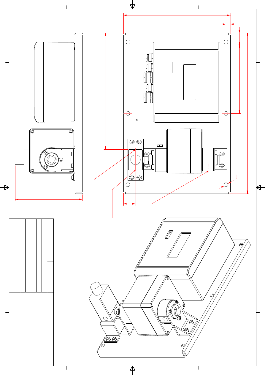
3.2
Placement of the skid
The JOWA SEAGUARD should be placed on a plane vertical surface and
bolted using the pre drilled holes in the base plate. When installing the unit it is
important to leave a minimum of 500mm working space in front of the unit (see
mechanical drawings chapter).
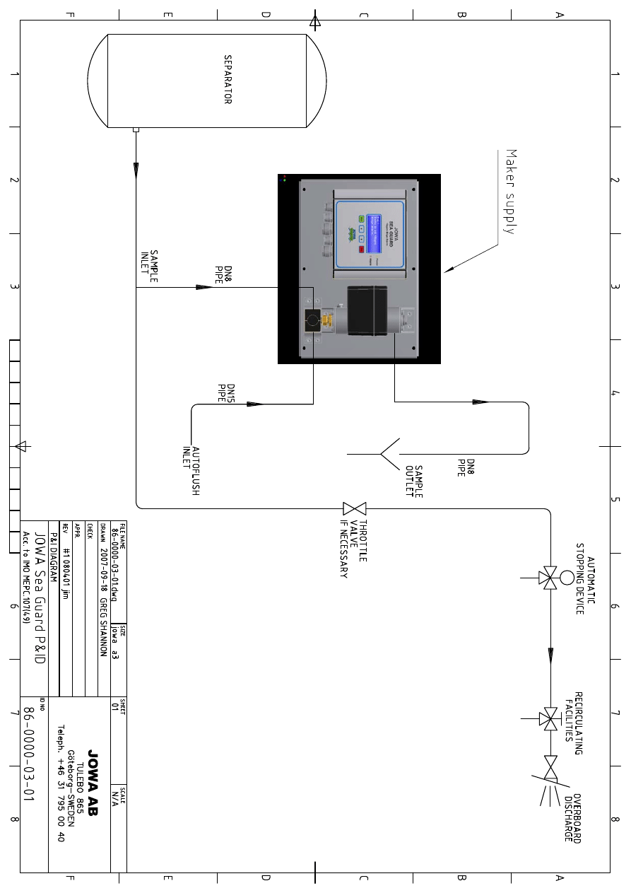
3.3 Pipe
Connections
All pipe connection points are G ¼” female threads (see mechanical drawings
chapter). Piping layout from the separator to the JOWA SEAGUARD should
follow the schematic shown in the flow diagram chapter.
3.4 Electric
Connections
The electrical equipment of the JOWA SEAGUARD is ready for installation
when delivered. The power supply should be single phase 230 VAC 50/60Hz.
Other power supplies on request. See the electrical drawings for further
information.
Connect the main cable to terminal J1 1,2 in the main control box.
Date:
Rev:
Sign:
2007-09-07
6. 080616
GS/jim
JOWA SEAGUARD
15ppm Bilge Alarm
K:\1-NYA K\1.2-JOWA PRODUKTER\JOWA 15PPM Bilge Alarm\Manual
9
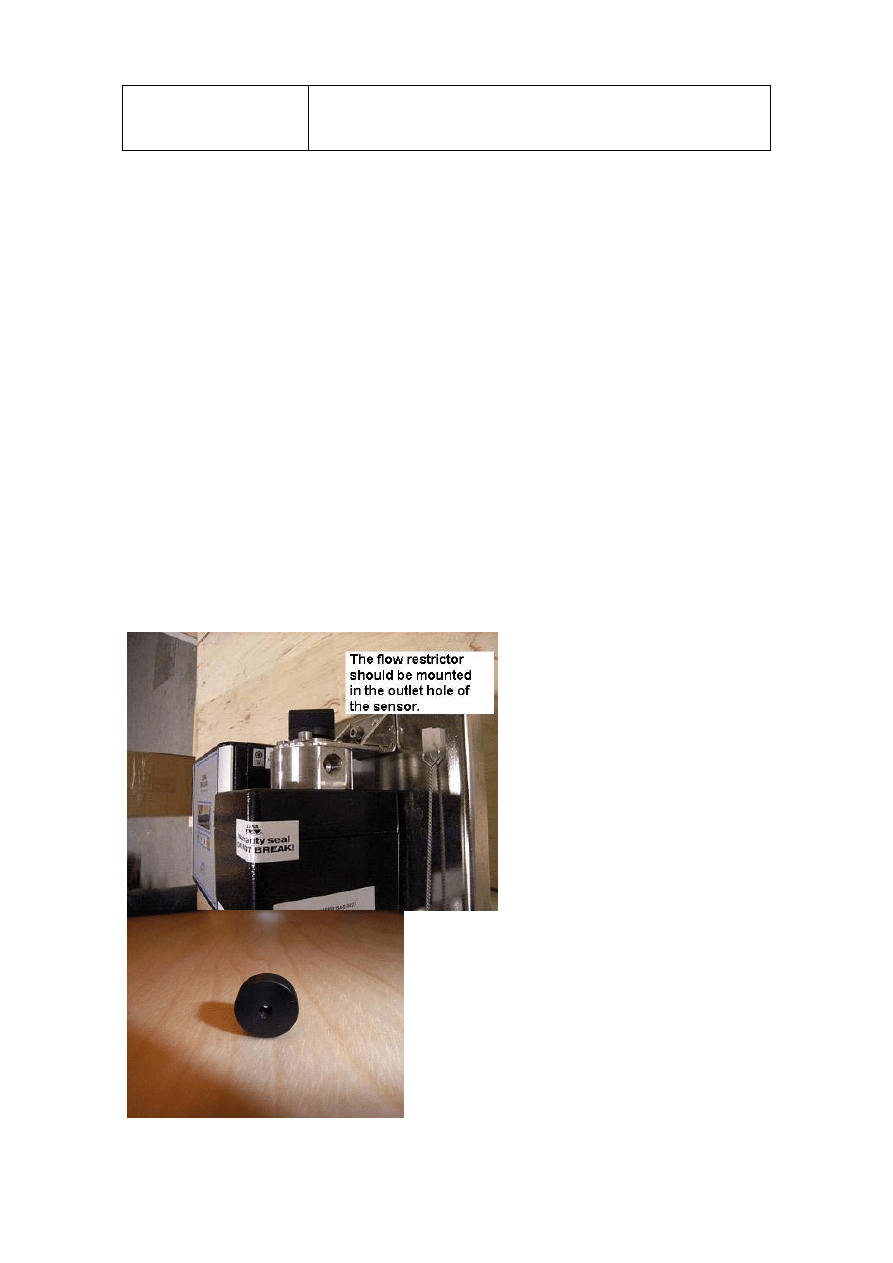
3.5
Adjusting the back pressure / flow in the sensor
To adjust the back pressure/ flow in the sensor there is a small flow restrictor in
the sample outlet connection. The flow restrictor is only 11mm in Diameter/
4mm thick and the orifice is 1mm.
The flow restrictor is located behind the coupling that is mounted in the sample
outlet.
Standard delivery is 1mm, but if this is too small hole, it is very easy to drill a
bigger hole.
It is recommendable to drill only 1 millimetre each time and then test again to se
if the back pressure/ flow are ok.
When the Bilge alarm is delivered as a loose item, the flow restrictor is delivered
in a bag taped on to the bilge alarm.
This flow restrictor should always be mounted in the outlet hole before the
coupling is connected.

Date:
Rev:
Sign:
2007-09-07
6. 080616
GS/jim
JOWA SEAGUARD
15ppm Bilge Alarm
K:\1-NYA K\1.2-JOWA PRODUKTER\JOWA 15PPM Bilge Alarm\Manual
10
4.0 System Function Description.
This chapter provides a detailed description of the unique functions of the
JOWA SEAGUARD. It is intended that the information in this chapter may be
used to help the operator optimise the JOWA SEAGUARD performance to his
or her specific bilge requirements.
4.1 Basic Functions
The main task of the JOWA SEAGUARD is to monitor the oil content of the
effluent from a bilge water separator and alarm if the oil content exceeds
15ppm. The JOWA SEAGUARD also logs specific events from the separator
and the JOWA SEAGUARD. These logs are useful in connection with
inspections.
4.2 Alarms
There are 2 alarm out signals which are triggered by the ppm oil content of the
separators effluent or by internal error codes. The first alarm triggers when the
effluent goes over the alarm’s set point. If the ppm oil content of the separators
effluent remains over this set point for a defined period the second alarm is
triggered. The alarm set points and time delays are adjustable.
4.3 Logged
Data
The JOWA SEAGUARD log is controlled by a signal from the separator and is
saved on a removable SD card . NOTE! The SD card is sealed against
unauthorised removal. The log updates every minute if there is no new events
occurring within the minute. The following data is logged:
• Date/GMT
time
• Start/stop of the log
• Auto flush start/stop
• High ppm alarm
• Alarm reset (under 15ppm)

Date:
Rev:
Sign:
2007-09-07
6. 080616
GS/jim
JOWA SEAGUARD
15ppm Bilge Alarm
K:\1-NYA K\1.2-JOWA PRODUKTER\JOWA 15PPM Bilge Alarm\Manual
11
4.3.1 Format of the log names
The logs are named following the following routine:
YY-MM-DD-HH:TT:SS
YY = year e.g. 06 for 2006
MM = month, 01-12
DD = day, 01-31
HH= hour, 00-24
TT= min, 00-60
SS= sec,00-60
4.3.2 Format of the logged data
PPM = actual PPM value at recorded time.
Lim = the ppm set point for alarm.
Sep = status for separator. (0 = inactive, 1 = active)
Val = position for 3-way valve.(0 = sample, 1 = clean water)
Al1 = condition for ALARM1
(0 = inactive, 1 = active)
Al2 = condition for Alarm2
(0 = inactive, 1 = active)
Sim = simulation mode ( 0 = inactive, 1 = active)
Err = Error code. (00 = no errors)
4.3.3 Auto
flush
Auto flush function cleans the sensor. During auto flush both alarms are
activated.
Auto flush occurs according to the following steps:
0
Both alarms are triggered at the same time.
1
2 seconds pause
2
Valve changes to clean water
3
Flushing for 20 seconds (adjustable)
4
Re-zero of the sensor (takes 13 sec)
5
Valve changes to sample water
6
2 seconds pause
7
Alarms released, ready
NOTE:
When auto flush is enabled, an auto flush procedure is performed when the
separator is started and when it is stopped. If the re-zero action fails at start up,
a second flush procedure is performed.

Date:
Rev:
Sign:
2007-09-07
6. 080616
GS/jim
JOWA SEAGUARD
15ppm Bilge Alarm
K:\1-NYA K\1.2-JOWA PRODUKTER\JOWA 15PPM Bilge Alarm\Manual
12
5.0 The Menu System
This chapter gives the operator detailed information on the JOWA SEAGUARD
menu system.
5.1
General Overview of the Menu tree
2 0 0 8 -
0 2 -
1 2
1 0 :
0 0 :
0 0
P P M :
1 0
S T A N D B Y
V a l
v e :
S A M P L E
A l
r m 1 :
O F F
A l
r m 2 :
O F F
↕
〉 S e r v i
c e
m e n u
S e t
t
i
n g s
m e n u
L o g
m e n u
I
n f
o r m a t
i
o n
m e n u
J O W A
I
n f
o
↕
S E R V I
C E
M E N U
〉 A l
a r m
l
i
s
t
C l
e a n
s
e n s
o r
S i
g n a l
s
S i
m u l
a t
i
o n
P a s
s
w o r d
p r o t
e c t
e d
↕
S E T T I
N G S
M E N U
〉 A l
a r m
o u t
p u t
s
C u r r e n t
o u t
p u T
A u t
o f
l
u s
h
↕
L O G
M E N U
〉 L i
s
t
l
o g
f
i
l
e s
P r i
n t
l
o g s
o n
R S 2 3 2
↕
I
N F O R M A T I
O N
M E N U
〉 C o n t r o l
u n i
t
S e n s
o r
u n i
t
↕
J O W A
A B
T u l
e b o v ä g e n
1 0 4
S E -
4 2 8
3 4
K å l
l
e r e d

Date:
Rev:
Sign:
2007-09-07
6. 080616
GS/jim
JOWA SEAGUARD
15ppm Bilge Alarm
K:\1-NYA K\1.2-JOWA PRODUKTER\JOWA 15PPM Bilge Alarm\Manual
13
G ö t
e b o r g ,
S W E D E N
+ 4 6
3 1
7 2 6
5 4
0 0
i
n f
o @ j
o w a .
s
e
w w w .
j
o w a .
s
e
5.2
Navigating the menus
Note!
It is only four lines at a time visible in the display. To scroll, use the arrow
UP or DOWN. This applies in all menus.
A alternative is confirmed by the Yes key and aborted by the no key. Values
are adjusted with the up/down keys.
5.3 Pages in the menu system
5.3.1 Main Page
2 0 0 8 -
0 2 -
1 2
1 0 :
0 0 :
0 0
P P M :
1 0
S T A N D B Y
V a l
v e :
S A M P L E
A l
r m 1 :
O F F
A l
r m 2 :
O F F
On the main page, the date, GMT (Greenwich Mean Time) is shown, actual
ppm, alarm status, 3-way valve position and log status. STANDBY= logging off.
RUN= logging on.
5.3.2 Service Menu
S E R V I
C E
M E N U
〉 A l
a r m
l
i
s
t
C l
e a n
s
e n s
o r
S i
g n a l
s
S i
m u l
a t
i
o n
P a s
s
w o r d
p r o t
e c t
e d
Alarm list is showing the presents alarms. Press Yes to enter the list.

Date:
Rev:
Sign:
2007-09-07
6. 080616
GS/jim
JOWA SEAGUARD
15ppm Bilge Alarm
K:\1-NYA K\1.2-JOWA PRODUKTER\JOWA 15PPM Bilge Alarm\Manual
14
5.3.3 Clean sensor
S E R V I
C E
M E N U
A l
a r m
l
i
s
t
〉 C l
e a n
s
e n s
o r
S i
g n a l
s
S i
m u l
a t
i
o n
P a s
s
w o r d
p r o t
e c t
e d
Back-flushing of the cell according to the “auto flush” routine described earlier in
this manual. Cleaning finishes with a re-zero of the sensor and the result is
shown in the display.
5.3.4. Signals
I
N
&
O U T
S I
G N A L S
S e p
i
n :
P A S S I
V E
F l
o w
i
n :
P A S S I
V E
S p a r e
i
n :
P A S S I
V E
V a l
v e
o u t
:
P A S S I
V E
A l
a r m 1 :
o u t
:
P A S S I
V E
A l
a r m 2 :
o u t
:
P A S S I
V E
A l
a r m
l
e d :
P A S S I
V E
Sep in = separator run signal.
Flow in= spare.
Spare in = spare.
Valve out = solenoid valve
Alarm1 out = alarm 1
Alarm2 out = alarm 2
Alarm led= LED- alarm signal to display
Passive and active are the possible values for all signals.

Date:
Rev:
Sign:
2007-09-07
6. 080616
GS/jim
JOWA SEAGUARD
15ppm Bilge Alarm
K:\1-NYA K\1.2-JOWA PRODUKTER\JOWA 15PPM Bilge Alarm\Manual
15
5.3.5 Simulation.
According to MEPC 107(49) § 4.2.5, onboard testing according to the
manufacturers instructions shall be permitted.
To facilitate this the JOWA 15ppm bilge alarm has a service menu called
simulation. A simulation run permits the user to imitate a ppm over the alarm set
point, (max alarm set point 15ppm).
This simulation run works by simulating the ppm ramping up from the real ppm
to a peak of 20ppm and down to the real ppm again.
-In this case “real ppm” refers to the ppm which is actually present.
Each ppm step in the simulation run takes 2 seconds. If, for example, the real
ppm is 10ppm when the simulation is started the alarm counts up from 10ppm
to 20ppm. If at the end of this simulation the real ppm is now 8ppm the count
down stops here
NOTE!
-If the real ppm value is higher than 15ppm then it is not possible to start a
simulation run
-During simulation the alarm continually monitors the real ppm in the
background. If at any time during a simulation run the real ppm goes higher
than 15ppm, there will be an alarm.
-All simulation runs are logged if the Sep in signal is active.

Date:
Rev:
Sign:
2007-09-07
6. 080616
GS/jim
JOWA SEAGUARD
15ppm Bilge Alarm
K:\1-NYA K\1.2-JOWA PRODUKTER\JOWA 15PPM Bilge Alarm\Manual
16
To perform a simulation choose the “Simulation” from the Service menu and
press YES, now the below display will be presented.
P r e s
s
Y e s
t
o
s
t
a r t
t
h e
P P M
s
i
m u l
a t
i
o n
p r o c e d u r e .
P r e s
s
N o
t
o
c a n c e l
Start the separator and then press YES to start the simulation.
If the separator isn’t running there will be no log on the simulation.
S i
m u l
a t
i
o n
s
t
a r t
e d !
First “Simulation Started!” will appear for a few seconds.
2 0 0 8 -
0 2 -
1 2
1 0 :
0 0 :
0 0
P P M :
1 0
R U N .
.
.
V a l
v e :
S A M P L E
A l
r m 1 :
O F F
A l
r m 2 :
O F F
In this window the ppm is increasing from the ”real” ppm to 20ppm
And then back to the “real” ppm again. When the “simulated” ppm reach
The alarm limit the alarm will appear and the OBV will close. Then the
ppm will reach to 20, and then it will go back to “real” ppm again.
S i
m u l
a t
i
o n
d o n e !
After the Simulation this window will appear and the bilge alarm is
Going back to normal run. One log file is created on the simulation.
5.3.6 Password Protected
These menus are only available to authorised service engineers

Date:
Rev:
Sign:
2007-09-07
6. 080616
GS/jim
JOWA SEAGUARD
15ppm Bilge Alarm
K:\1-NYA K\1.2-JOWA PRODUKTER\JOWA 15PPM Bilge Alarm\Manual
17
5.3.7 Settings Menu
S E T T I
N G S
M E N U
〉 A l
a r m
o u t
p u t
s
C u r r e n t
o u t
p u t
A u t
o f
l
u s
h
To make changes in the main programmes parameters the user must navigate
to ‘settings’ where the user can change the settings for the alarms, valve, auto
flush and current out.
5.3.8 Valve/Alarm1/Alarm2
A L A R M
S E T T I
N G S
〉 P P M
l
i
m i
t
:
1 5
t
a l
a r m 1 :
0
[
S ]
t
a l
a r m 2 :
0
[
S ]
The different alarms have different delays and the ppm setting can be adjusted
between 0.0 and 15.0.
C U R R E N T
O U T P U T
M O D E
〉 [
]
0
t
o
2 0
m A
[
X ]
4
t
o
2 0
m A
The 4-20mA signal level can be adjusted where (0) 4 mA is equivalent to
0ppm, and 20 mA is equivalent to 30ppm.
5.3.9 Auto flush
A U T O F L U S H
S E T T I
N G S
〉 A u t o f l
u s
h :
O N
t
s
t
a r t
:
3 0
[
S ]
t
e n d :
3 0
[
S ]
000-540 [s]
Auto flush can be shut off or set under the settings menu. It is also possible to
set the length of time per auto flush, (t).

Date:
Rev:
Sign:
2007-09-07
6. 080616
GS/jim
JOWA SEAGUARD
15ppm Bilge Alarm
K:\1-NYA K\1.2-JOWA PRODUKTER\JOWA 15PPM Bilge Alarm\Manual
18
5.3.10 Log Menu
L O G
M E N U
〉 L i
s
t
l
o g
f
i
l
e s
P r i
n t
l
o g s
o n
R S 2 3 2
If choosing “print logs on RS232” all logs will be printed.
5.3.11 List log files.
E n t
e r
d a t
e :
-
2 0 0 8 -
0 3 -
3 1
-
By choosing “list log files” you are able to choose any log
At the memory card by date.
5.3.12 Log files
L O G
F I
L E S
〉 2 0 0 8 - 0 3 - 3 1
0 6 :
1 5 :
0 2
P r e v i
o u s
d a y
N e x t
d a y
When one specific log is chosen, press yes and then you will
Get to the window below. It is also possible to se log events next
day or previous day.
-
-
-
-
-
-
-
1
/
7 -
-
-
-
-
-
-
-
2 0 0 8 -
0 3 -
3 1
0 6 :
1 5 :
0 2
P P M = 0
L i
m = 1 5
E r r = 0 0
S = 1
V = 0
A 1 = 0
A 2 = 0
Every log is marked with start date and time, ppm, alarm and
valve position. Of (X/Y), X is log number of Y, total logs.
A log of format ’-----(X/Y)----------’ denotes a log without any
alarms, while ”====(X/Y)============” denotes a log with alarms.
PPM row shows the actual ppm value and the ppm alarm set point
and alarm. (Err=00 is normal) The bottom row shows the status for
alarm (A1) and (A2) valve position (V) (0=sample, 1=clean water).
separator status (S) (0 = inactive, 1 = active).
To get more options on the chosen log please press yes and
Then the below window will appear.

Date:
Rev:
Sign:
2007-09-07
6. 080616
GS/jim
JOWA SEAGUARD
15ppm Bilge Alarm
K:\1-NYA K\1.2-JOWA PRODUKTER\JOWA 15PPM Bilge Alarm\Manual
19
5.3.13 Print log on printer/RS232
By choosing “print on printer” a special printer from Jowa is needed.
By choosing Print on RS232 it is possible to print the log to a pc.
Instruction of how to download log files into a PC, and items needed.
1a. A serial cable of 0-modem type, with two female 9 pin connectors. Connect
one end of the cable to RS232 connection at the Bilge alarm power board and
the other end to your PC’s serial COM port.
If your PC doesn’t have a serial com port it is possible to use a converter from
USB to RS232. Both, the 0-modem cable and the converter is possible to by
from JOWA.
2. A terminal program (it’s standard in all windows program)
Windows has one under Start-program-accessories-communication-hyper
terminal.
A
. A window pop up and says new connection, name it “Bilge alarm”, OK
B
. Next window, choose the com port where you have connected the cable, OK
C
. Properties for the COM port should be adjusted as follows:
Bits per second: 9600
Data bits:
8
Parity:
none
Stop bits:
1
Flow control:
none
D
. Within the terminal program, choose menu Transfer and “fetch text to file”
some computers has “capture text”.
E
. A new window pop up where to save, browse and choose desktop and a file
name e.g. bilge alarm.txt , save and start.
A C T I
O N
O N
L O G
〉 P r i
n t
o n
p r i
n t
e r
P r i
n t
o n
R S 2 3 2
A l
a r m
l
i
s
t
R e t
u r n
t
o
l
o g s
R e t
u r n
t
o
l
o g
m e n u

Date:
Rev:
Sign:
2007-09-07
6. 080616
GS/jim
JOWA SEAGUARD
15ppm Bilge Alarm
K:\1-NYA K\1.2-JOWA PRODUKTER\JOWA 15PPM Bilge Alarm\Manual
20
F
. At the Bilge alarm, go to the log menu and press YES, then choose “list log
files”. Now the display will show “Enter date” and you can choose the date that
you want by using YES, UP and DOWN arrow. After entering date, press YES.
Please choose the log that you want to print and press YES.
Choose print on RS232 and press YES.
H
. Go back to the hyper terminal menu transfer and stop “fetch text to file”
I
. To se the log file, open the created file at the desktop “bilge alarm.txt” by
double clicking on it and the log file will be visible.
J
. When closing HyperTerminal, Windows ask you if you want to save the
configured HyperTerminal, by clicking Yes the setup is saved until next time you
want to use it. You find it under Start-Program-Accessories-Communication-
HyperTerminal-Bilge alarm.
5.3.14 Alarm list
If an Error e.g.(Err=10) is presented in the log and to se what alarm it is please
press choose “Alarm list” and press YES. Now the error is presented.
A C T I
O N
O N
L O G
P r i
n t
o n
p r i
n t
e r
P r i
n t
o n
R S 2 3 2
〉 A l
a r m
l
i
s
t
R e t
u r n
t
o
l
o g s
R e t
u r n
t
o
l
o g
m e n u

Date:
Rev:
Sign:
2007-09-07
6. 080616
GS/jim
JOWA SEAGUARD
15ppm Bilge Alarm
K:\1-NYA K\1.2-JOWA PRODUKTER\JOWA 15PPM Bilge Alarm\Manual
21
5.3.15 Information Menu
I
N F O R M A T I
O N
M E N U
〉 C o n t r o l
u n i
t
S e n s
o r
u n i
t
Choose Control unit or Sensor unit and press YES
5.3.16 Control Unit
C O N T R O L
U N I
T
I
D :
B A C -
0 0 0 1
S W
v e r :
S G
1 .
1 .
1
H W
v e r :
S G
R e v
B
ID information for The Complete Bilge alarm, main circuit board, software and
hardware
versions
5.3.17 Sensor Unit
S E N S O R
U N I
T
I
D :
B A S :
0 0 0 1
S W
v e r :
0 1 .
0 1 .
0 0
H W
v e r :
F
0 2
C a l
i
:
0 8 0 3 1 8 1 2 0 0
T e m p :
2 0
S t
a t
u s
r e g 1 :
0 x 0 0
S t
a t
u s
r e g 2 :
0 x 0 0
ID information for sensor, circuit board, software and hardware versions. Sensor
calibration date and time, sensor temperature.
5.3.18 JOWA info
J O W A
A B
T u l
e b o v ä g e n
1 0 4
S E -
4 2 8
3 4
K å l
l
e r e d
G ö t
e b o r g ,
S W E D E N
+ 4 6
3 1
7 2 6
5 4
0 0
i
n f
o @ j
o w a .
s
e
w w w .
j
o w a .
s
e
Jowa Contact info.

Date:
Rev:
Sign:
2007-09-07
6. 080616
GS/jim
JOWA SEAGUARD
15ppm Bilge Alarm
K:\1-NYA K\1.2-JOWA PRODUKTER\JOWA 15PPM Bilge Alarm\Manual
22
6.0 Maintenance
The JOWA SEAGUARD requires very little maintenance.
Weekly maintenance:
- Clean the sensor with the provided brush.
- Do an manual auto flush after the sensor is clean.
Go to the “service menu” and in that menu please choose “Clean Sensor”.
Now the fresh water is flushing the sensor and in the same time a clean
water calibration is done.
On every IOPP certificate renewal:
According to resolution MEPC.107(49) § 4.2.11
The accuracy of the 15 ppm Bilge Alarms should be checked at IOPP
Certificate renewal surveys according to the manufacturers instructions.
Alternatively the unit may be replaced by a calibrated 15 ppm Bilge Alarm.
The calibration certificate for the 15 ppm Bilge Alarm, certifying date of last
calibration check, should be retained onboard for inspection purposes.
The accuracy checks can only be done by the manufacturer or persons
authorized by the manufacturer.
On the JOWA 15PPM Bilge alarm it is only necessary to replace the sensor
unit.
With the sensor, a calibration certificate with the last calibrating date will follow.

Date:
Rev:
Sign:
2007-09-07
6. 080616
GS/jim
JOWA SEAGUARD
15ppm Bilge Alarm
K:\1-NYA K\1.2-JOWA PRODUKTER\JOWA 15PPM Bilge Alarm\Manual
23
7.0 Trouble
Shooting

Date:
Rev:
Sign:
2007-09-07
6. 080616
GS/jim
JOWA SEAGUARD
15ppm Bilge Alarm
K:\1-NYA K\1.2-JOWA PRODUKTER\JOWA 15PPM Bilge Alarm\Manual
24
ALARM LIST
ALARM CODE
ERROR REPORTED: POSSIBLE
CAUSE:
ACTION:
ERR: 2
Clock failure
Hard ware failure.
Replace the CPU
card.
ERR: 4
Memory failure
1. Memory card loose.
2. Memory card
broken.
1. Check the memory
card. And restart the
system.
2. Change memory
card
ERR: 8
Sensor disconnected
1. Cable to the sensor
loose or broken.
2. Sensor broken.
1. Check the cable.
2. Replace the sensor
ERR: 10
Clean sensor
1. No FW. supply
2. Dirty sensor
3.Autoflush failed
1. Check FW. Supply
2. Clean sensor.
3. Clean sensor and
do another auto flush.
ERR: 20
Sensor temperature.
The temperature in the
sensor is out of range.
( +1-60 degrees
Celsius)
1. Check temperature
on the sample water.
2. Check ambient
temperature.
ERR: 80
Unspecified error.
Soft ware failure.
Restart the system.
(power off / power on)
PPM: O/R
Clean sensor
Outside PPM range
1. PPM out of
measuring area (o-
30ppm, trend up to
40ppm)
2. To dirty sample
water.
1. Clean sensor and
do a clean water
calibration.
2. Check the sample
water.

Date:
Rev:
Sign:
2007-09-07
6. 080616
GS/jim
JOWA SEAGUARD
15ppm Bilge Alarm
K:\1-NYA K\1.2-JOWA PRODUKTER\JOWA 15PPM Bilge Alarm\Manual
25
DISPLAY TEXT
INFO TEXT
EXPLANATION
A new clean attempt is started.
If the first auto clean is failed, a second
attempt will be started.
The power disconnected,
please wait
At start up or power failure this message
will appear.
A log operation was active when power
was disconnected.
If the running signal to the Bilge alarm is
on when the power is disconnected this
message will appear.
Printing
Please wait.
This text will pop up on the display when
a log is printed.
Opening a log for another Serial no.
If another memory card is installed in the
bilge alarm, it is possible to read the log
files.
Checksum error in log file.
File can not be opened.
This message can appear when the
memory card is manipulated.
Checksum error.
The following info could be incorrect.
This message can appear when the
memory card is manipulated.
The memory card is not for this unit.
Incorrect memory card.

Date:
Rev:
Sign:
2007-09-07
6. 080616
GS/jim
JOWA SEAGUARD
15ppm Bilge Alarm
K:\1-NYA K\1.2-JOWA PRODUKTER\JOWA 15PPM Bilge Alarm\Manual
26
8.0 Flow Diagram (P & I)

Date:
Rev:
Sign:
2007-09-07
6. 080616
GS/jim
JOWA SEAGUARD
15ppm Bilge Alarm
K:\1-NYA K\1.2-JOWA PRODUKTER\JOWA 15PPM Bilge Alarm\Manual
27
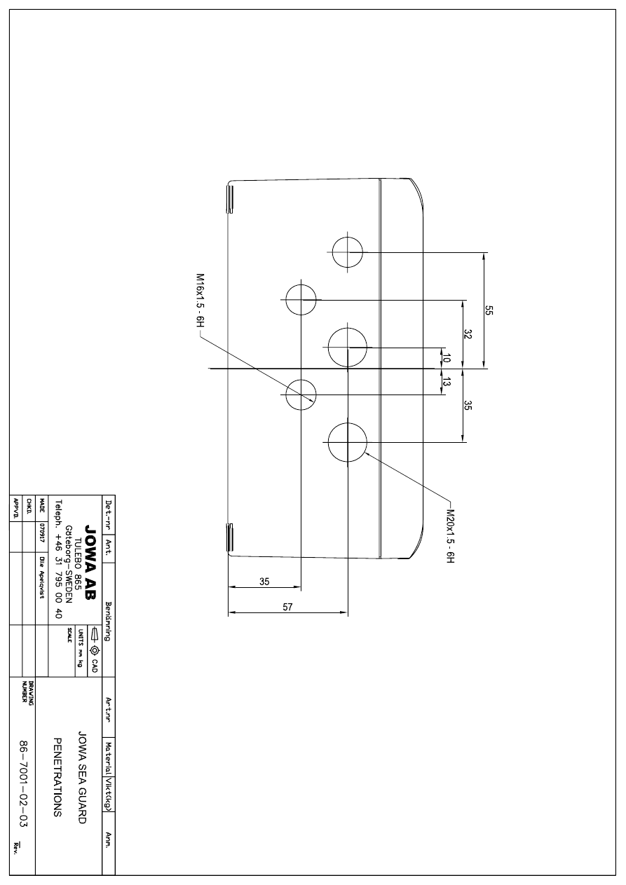
9.0 Mechanical
Drawings
1
1
2
2
3
3
4
4
5
5
6
6
A
A
B
B
C
C
D
D
CHECK
RE
V
AP
PR
.
DRAWN
FI
LE
N
A
M
E
SI
ZE
ID
N
O
MODE
L I
D
SCA
LE
JO
W
A
AB
TU
L
E
B
O
86
5
Götebor
g
-SW
E
D
E
N
T
e
le
p
h
. +4
6
3
1
726
54
0
0
86
-0
000
-0
1-0
1 -
JOWA
S
eag
uar
d.i
am
A3
G
reg Sha
nnon
#2 080
401 ES
86
-000
0-
01
86-00
00
-0
1
200
7-06
-1
4
GA
Dr
aw
in
g
JOWA Sea G
uar
d
JO
WA
15
pp
m Bi
lg
e Al
ar
m
-0
1
151
T
O
T
A
L
WEI
G
T
H
A
PPROX 6
-7kg
360
240
10
20
n
9(x
6)
16
0
AU
TOF
LUS
H
INLE
T F
E
MA
LE
THREAD 1/
4"
SA
MPLE
IN
LET FEMALE
THR
E
AD 1/4"
SAMPLE
OU
TLET
FEM
A
LE
TH
REA
D
1/4"
27
26
1

Date:
Rev:
Sign:
2007-09-07
6. 080616
GS/jim
JOWA SEAGUARD
15ppm Bilge Alarm
K:\1-NYA K\1.2-JOWA PRODUKTER\JOWA 15PPM Bilge Alarm\Manual
28
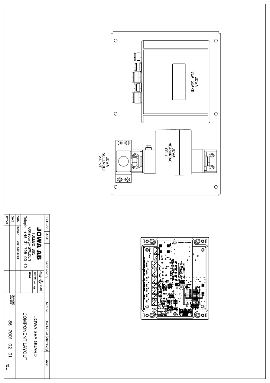
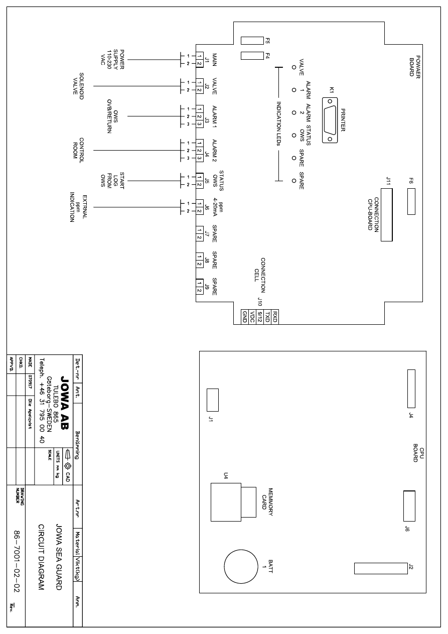
10.0 Electrical drawings

Date:
Rev:
Sign:
2007-09-07
6. 080616
GS/jim
JOWA SEAGUARD
15ppm Bilge Alarm
K:\1-NYA K\1.2-JOWA PRODUKTER\JOWA 15PPM Bilge Alarm\Manual
29
11.0 Spare Parts List

Date:
Rev:
Sign:
2007-09-07
6. 080616
GS/jim
JOWA SEAGUARD
15ppm Bilge Alarm
K:\1-NYA K\1.2-JOWA PRODUKTER\JOWA 15PPM Bilge Alarm\Manual
30
DESCRIPTION. PART
NUMBER.
Sensor unit
86003-00001
Power board
86001-00030
CPU board
86001-00031
SD card
86001-00033
3-way valve 230V
86001-00022
Cleaning brush
83070-00002
Fuse 1A
94007-52010
Fuse 0.5A
19099-00050

Date:
Rev:
Sign:
2007-09-07
6. 080616
GS/jim
JOWA SEAGUARD
15ppm Bilge Alarm
K:\1-NYA K\1.2-JOWA PRODUKTER\JOWA 15PPM Bilge Alarm\Manual
31
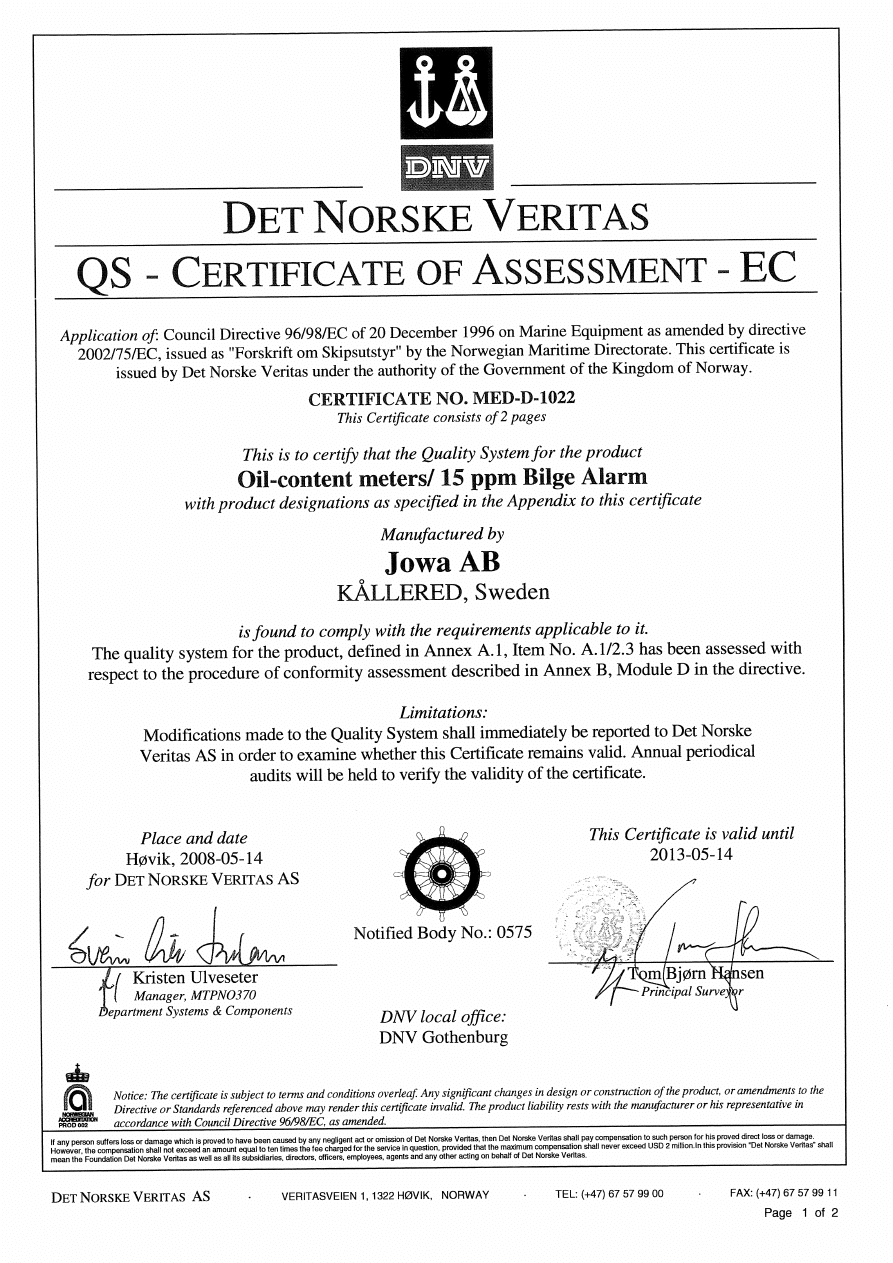
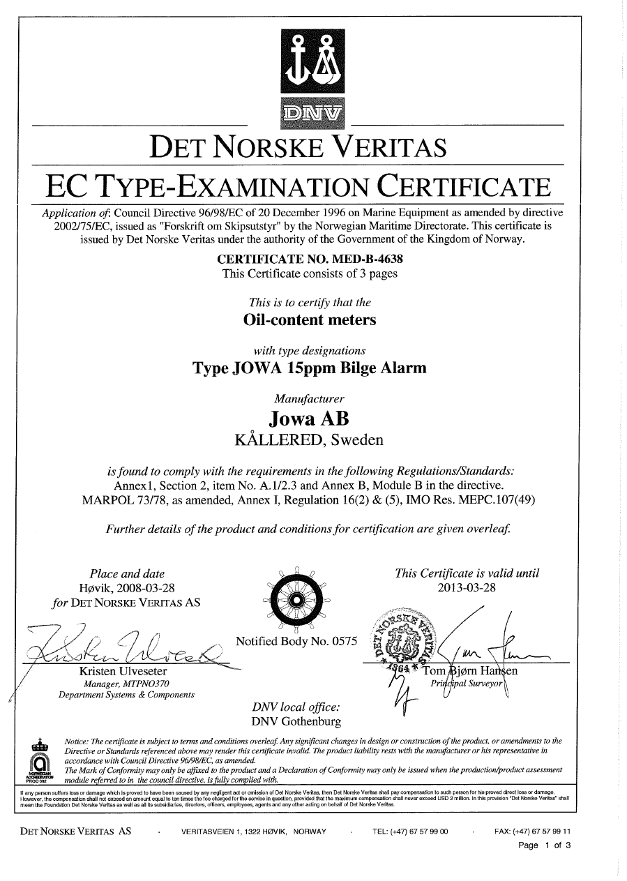
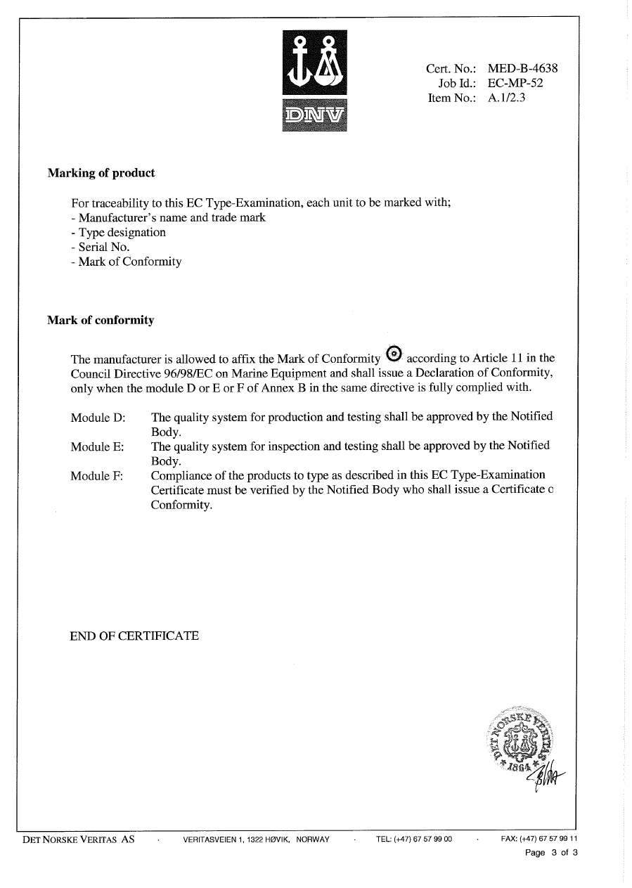
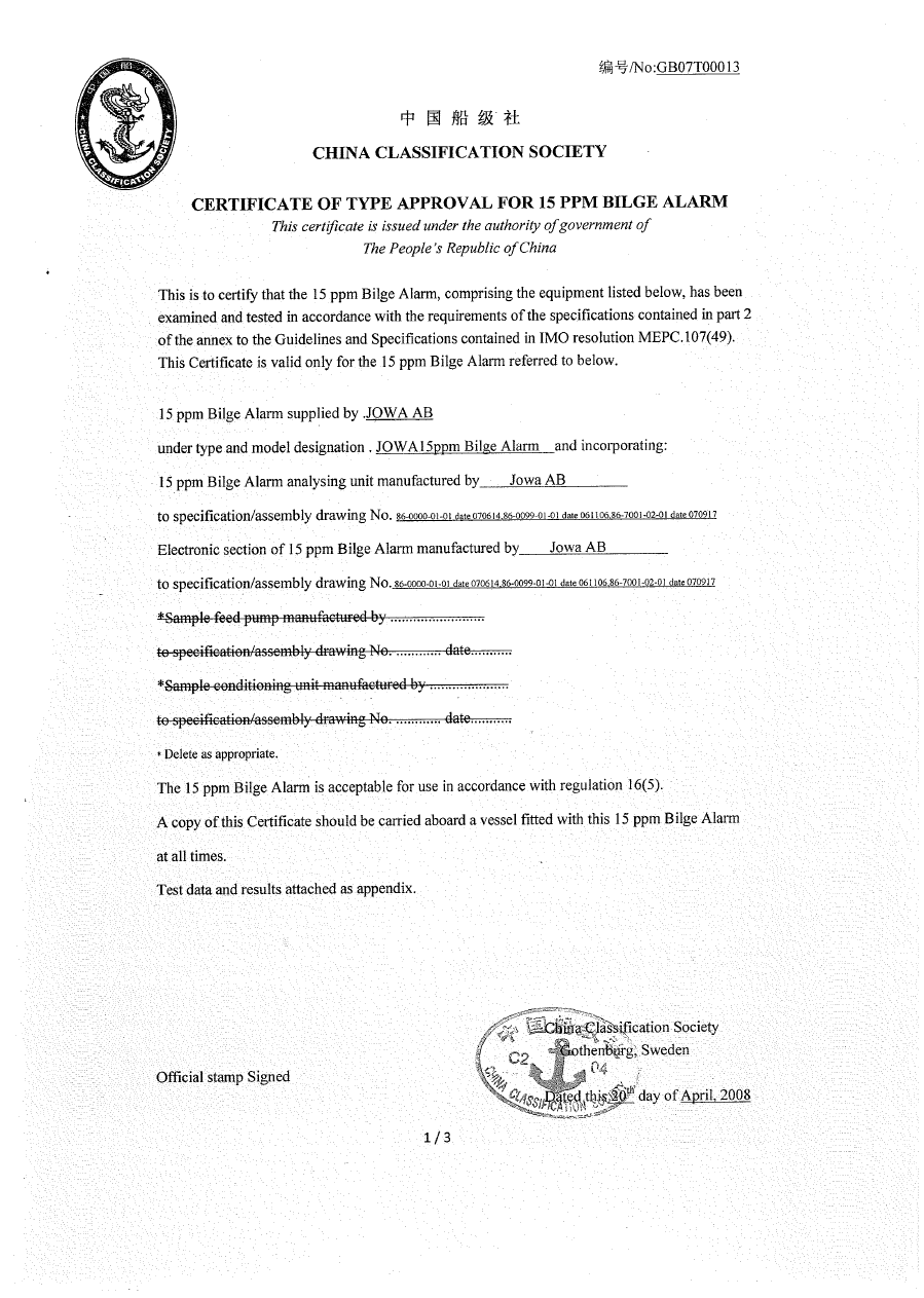
12.0 Approval Certificates
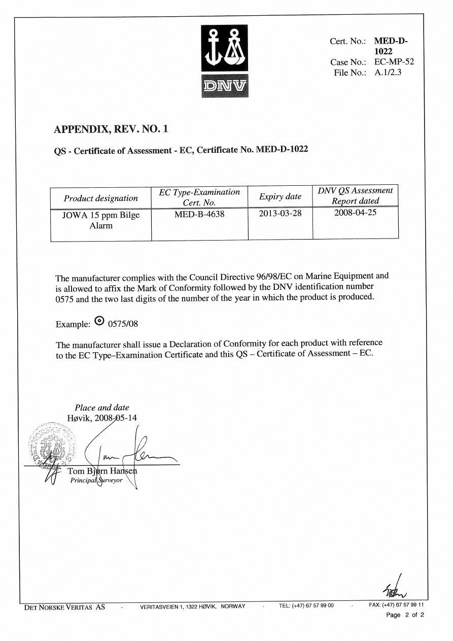

Coast Guard Approval Number: 162.050/9058/0 Expires: 30 January 2013
OIL POLLUTION PREVENTION EQUIPMENT
The following device has been tested in accordance with
IMO Resolution MEPC.107(49)
JOWA AB
Tulebo 865
S-428 34 Kallered
Gotheburg SWEDEN
JOWA Seaguard; 15 ppm Bilge Alarm
This is to certify that the equipment listed has been examined and tested in accordance with
the requirement of the specifications contained in annex 13 to the guidelines and
specifications contained in IMO resolution MEPC.107(49).
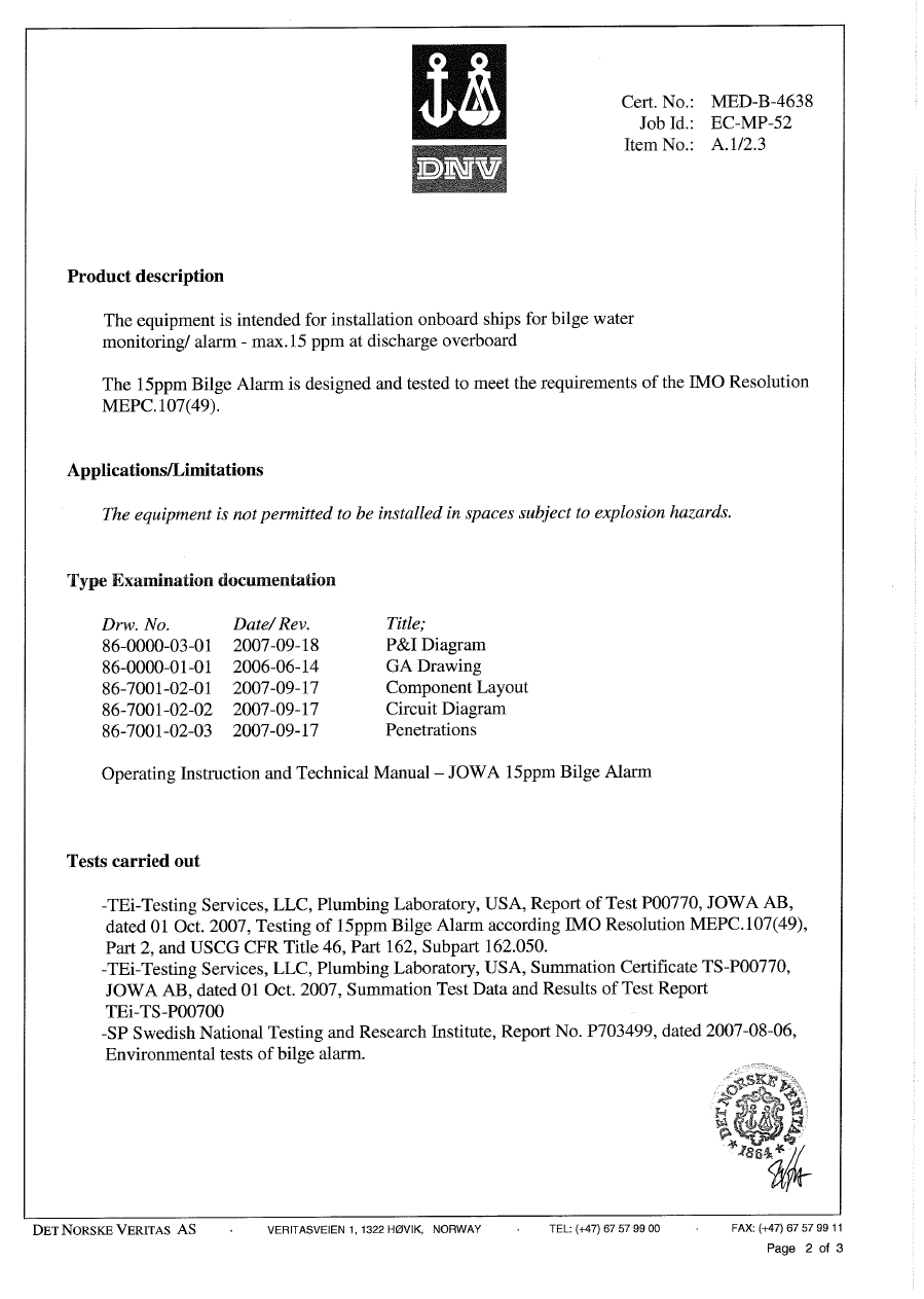
Equipment is manufactured by JOWA AB to specification/assembly drawing No. 86-0000-03-01
dated 9/18/2007, No. 86-0000-01-01 dated 6/14/2007 and No. 86-7001-02-01 through 86-7001-02-
03 dated 9/7/2007. The unit is not certified for use in Hazardous Locations.
A copy of this Certificate should be carried aboard a vessel fitted with this equipment at
all times. IMO Certificates of Type Approval do not expire and are valid for equipment
manufactured at any time during the period of validity of this Certificate. Test data and
results are attached in the appendix.
This certificate documents compliance with 46 CFR 162.050.
*** END ***
THIS IS TO CERTIFY THAT the above named manufacturer has submitted to the undersigned satisfactory evidence that the item specified herein complies
with the applicable laws and regulations as outlined on the reverse side of this Certificate, and approval is hereby given. This approval shall be in effect until the
expiration date hereon unless sooner canceled or suspended by proper authority.
GIVEN UNDER MY HAND THIS 30
th
DAY OF
JANUARY 2008, AT WASHINGTON D.C.
T.
E.
MEYERS
Chief,
Engineering
Division
U.S. Coast Guard Marine Safety Center

TERMS:
The approval of the item described on the face of the Certificate has been based upon the submittal of satisfactory
evidence that the item complies with the applicable provisions of the navigation and shipping laws and the applicable regulations
in Title 33 and/or Title 46 of the Code of Federal Regulations. The approval is subject to any conditions noted on this Certificate
and in the applicable laws and regulations governing the use of the item on vessels subject to Coast Guard inspection or on other
vessels and boats.
Consideration will be given to an extension of this approval provided application is made 3 months prior to the
expiration date of this Certificate.
The approval holder is responsible for making sure that the required inspections or tests of materials or devices covered
by this approval are carried out during production as prescribed in the applicable regulations.
The approval of the item covered by this certificate is valid only so long as the item is manufactured in conformance
with the details of the approved drawings, specifications, or other data referred to. No modification in the approved design,
construction, or materials is to be adopted until the modification has been presented for consideration by the Commandant and
confirmation received that the proposed alteration is acceptable.
NOTICE: Where a manufacturer of safety-at-sea equipment is offering for sale to the maritime industry, directly or indirectly,
equipment represented to be approved, which fails to conform with either the design details or material specifications, or both, as
approved by the Coast Guard, immediate action may be taken to invoke the various penalties and sanctions provided by law
including prosecution under 46 U.S.C. 3318, which provides:
"A person that knowingly manufactures, sells, offers for sale, or possesses with intent to sell, any equipment subject to
this part (Part B. of Subtitle II of Title 46 U.S.C.). and the equipment is so defective as to be insufficient to accomplish the purpose
for which it is intended, shall be fined not more than
$10,000
, imprisoned for not more than 5 years or both."
APPENDIX
United States Coast Guard Certificate of Approval
Coast Guard Approval Number: 162.050/9058/0
Expires: 30 January 2013
TEST DATA AND RESULTS OF TESTS CONDUCTED ON A 15 PPM BILGE
ALARM IN ACCORDANCE WITH THE GUIDELINES AND SPECIFICATIONS CONTAINED
IN IMO RESOLUTION MEPC.107(49)
15 ppm Bilge Alarm submitted by:
TEi-Testing Services, LLC - Plumbing Laboratory
3455 South 500 West
Salt Lake City, UT 84115-4234
USA
Test location:
TEi-Testing Services, LLC - Plumbing Laboratory
Method of sample analysis:
ISO 9377-2-2000(E)
Samples analyzed by:
Director, Tei-Testing Services-Analytical Laboratory
Environmental testing of the electrical and electronic sections of the 15 ppm Bilge Alarm has been carried out in accordance with the
guidelines and specifications contained in IMO resolution MEPC.107(49). The equipment functioned satisfactorily on completion of each
test specified on the environmental test protocol.
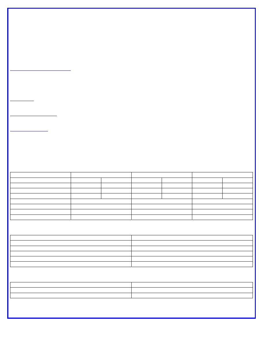
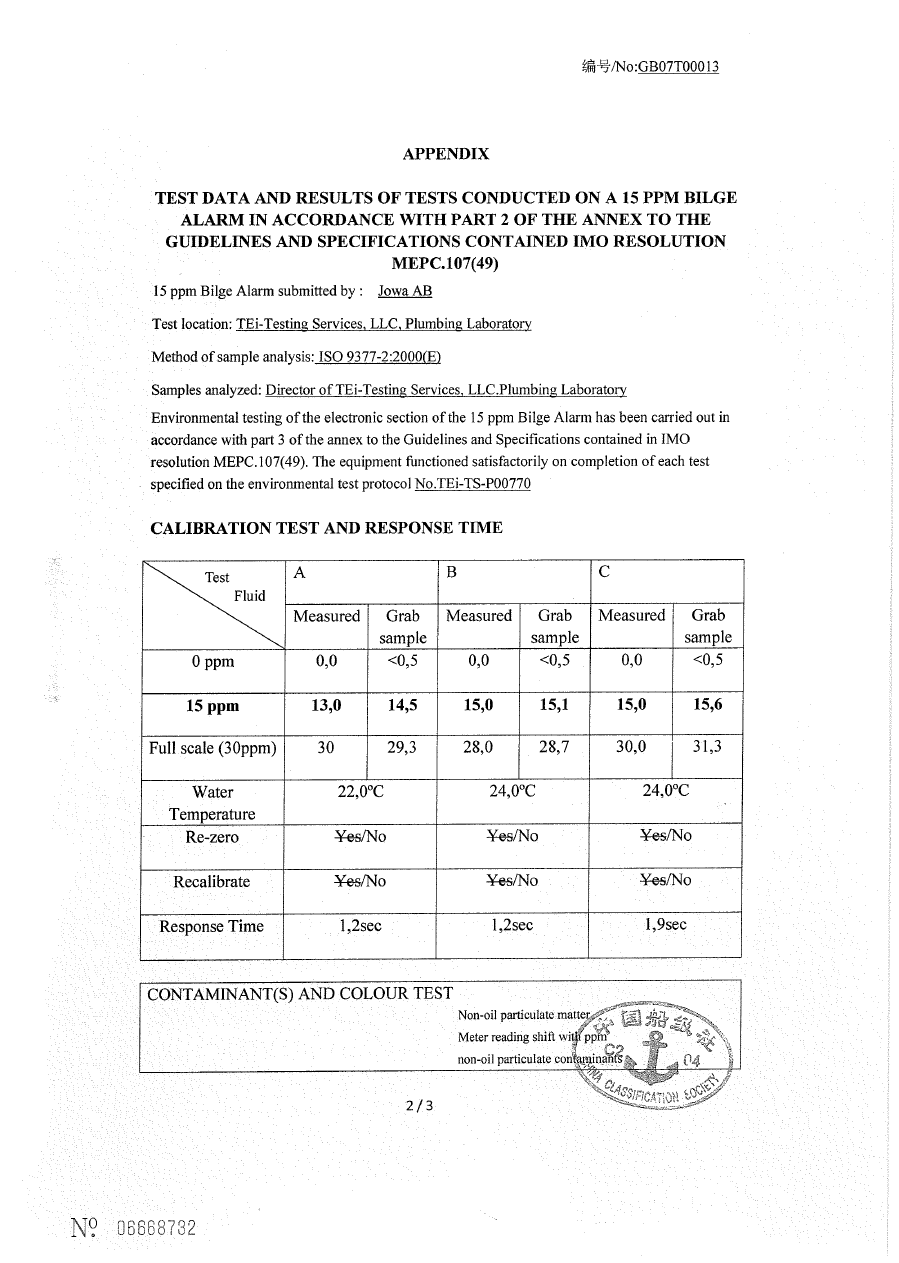
Calibration Test and Response Time Test
“A”
“B”
“C”
Measured
Grab
Measured Grab Measured Grab
0 ppm
0.0
< 0.5
0.0
< 0.5
0.0
< 0.5
15
ppm
13.0 14.5 15.0 15.1 15.0 15.6
Full
Scale
30.0 29.3 28.0 28.7 30.0 31.3
Water
Temperature 22.0°C 24.0°C 24.0°C
Re-zero
No No No
Recalibrate
No No No
Response Time (seconds)
1.2
1.2
1.9
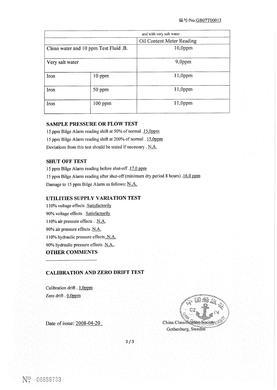
Contamination and Color Test
Oil Content Meter Reading
Clean Water and Test Fluid “B” at 10 ppm
10.0 ppm
Very Salt Water and Test Fluid “B” at 10 ppm
9.0 ppm
Iron Oxide at 10 ppm
11.0 ppm
Iron Oxide at 50 ppm
11.0 ppm
Iron Oxide at 100 ppm
11.0 ppm
Sample Pressure or Flow Test
15 ppm Bilge Alarm reading shift at 50% of normal
0 ppm
15 ppm Bilge Alarm reading shift at 200% of normal
0 ppm
Deviations:
No deviations to the test method were made.
(1 of 2)
APPENDIX
United States Coast Guard Certificate of Approval
Coast Guard Approval Number: 162.050/9058/0
Expires: 30 January 2013
TEST DATA AND RESULTS OF TESTS CONDUCTED ON A 15 PPM BILGE
ALARM IN ACCORDANCE WITH THE GUIDELINES AND SPECIFICATIONS CONTAINED
IN IMO RESOLUTION MEPC.107(49)
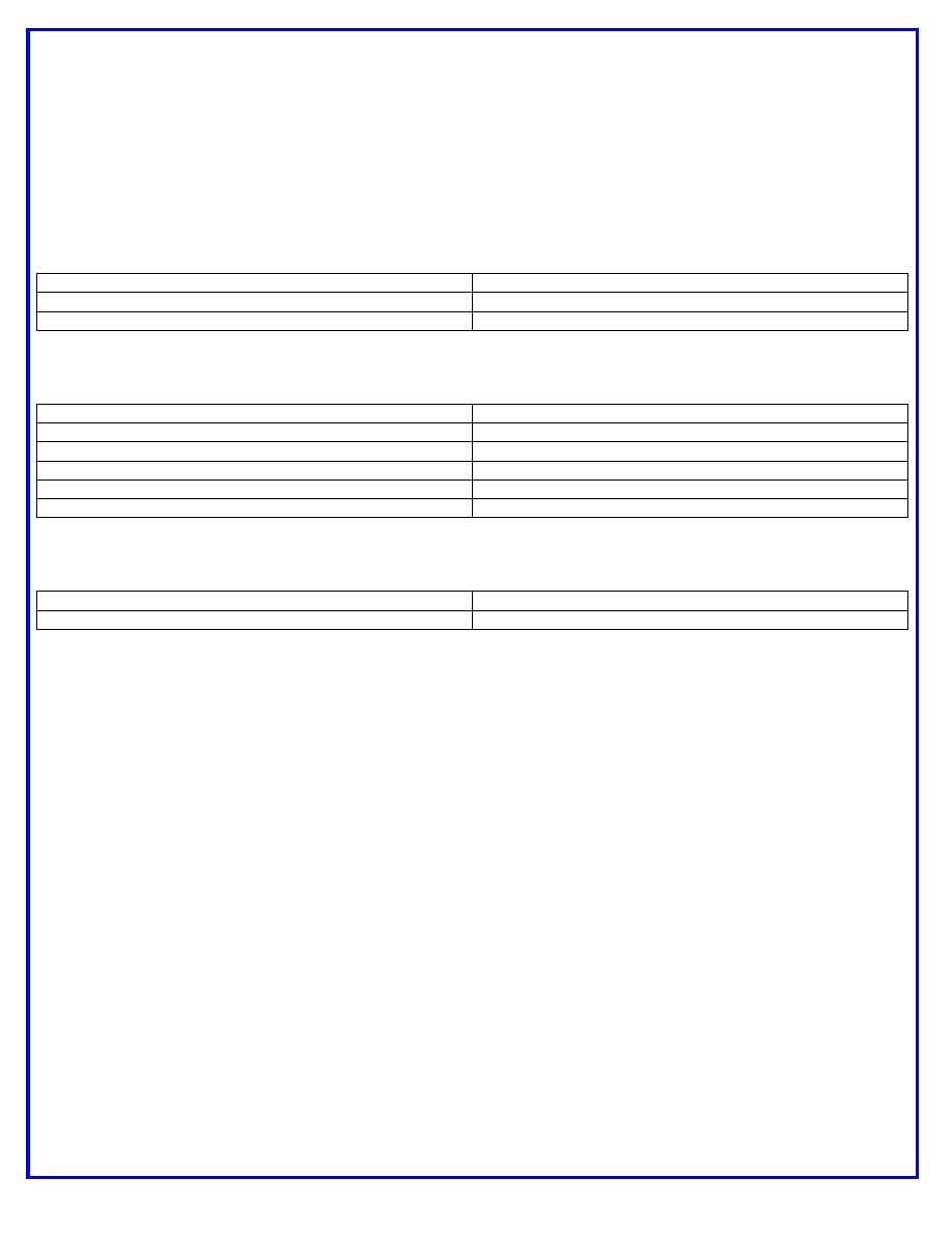
Shut Off Test
15 ppm Bilge Alarm reading before shut off
17.0 ppm
15 ppm Bilge Alarm reading after shut off
16.0 ppm
Damage to 15 ppm Bilge Alarm:
No damage was caused by this test to the 15 ppm Bilge Alarm.
Utilities Supply Variation Test
110% Voltage Effects
There was no change in the Bilge Alarm reading.
90% Voltage Effects
There was no change in the Bilge Alarm reading.
110% Air Pressure Effects
Not Applicable
90% Air Pressure Effects
Not Applicable
110% Hydraulic Pressure Effects
Not Applicable
90% Hydraulic Pressure Effects
Not Applicable
Calibration and Zero Drift Test
Calibration Drift
1.0 ppm
Zero Drift
0.0 ppm
Diagram of test rig attached.
Diagram of sampling arrangement attached.
*** END ***
(2 of 2)
Document Outline
- flow.pdf
- Model
- Layout2
Wyszukiwarka
Podobne podstrony:
Jowa OWS 15ppm bilge alarm new 15
Jowa OWS 15ppm bilge alarm new
JOWA OWS Diagram
JOWA 3 SEP OWS Manual + deckmaRev Oil content meter 2
JOWA 3 SEP OWS Manual
JOWA 3 SEP OWS Manual + deckmaRev Oil content meter
JOWA 3 SEP OWS Pump Mono
JOWA 3 SEP OWS Pump Mono
Prezentacja KST 2007 new
new employee safety orientation 1201643571904060 5
jakość 1 new
Active new pl 200605
CHRYSLER NEW YORKER 1994
więcej podobnych podstron