INSTRUCTION MANUAL
FOR
MOTOR-DRIVEN GEAR PUMPS
No. 3-1A
12143-3055-E
Page
1
of
12
No.3-1A
INSTRUCTION MANUAL
FOR
MOTOR DRIVEN GEAR PUMPS
Date:
15 March 2000
Contents Page
Safety Instructions
2
1. Purpose
3
2. Scope of Application
3
3. Outline of Construction
3
4. Transport
3
5. Prevention of Vibration
3
6. Installation
4
7. Piping
4
8. Connection
8-1 Alignment
8-2 Checking of alignment for sure flex coupling
4
9. Operation
9-1 Preparation before Operation
9-2 Operation
9-3 Stopping
6
10. Maintenance
10-1 Cautions during Operation
10-2 Cautions during Standstill
7
11. Inspection
11-1 Periodical Inspection
11-2 Overhaul
11-3 Assembly
8
12. Troubles and Remedies
11
Page
2
of
12
No.3-1A
INSTRUCTION MANUAL
FOR
MOTOR DRIVEN GEAR PUMPS
Date:
15 March 2000
SAFETY INSTRUCTIONS
CAUTIONS FOR YOUR SAFETY
Before using this pump, read the INSTRUCTION MANUAL (S). Follow WARNING LABEL(S),
INSTRUCTION (S) and CAUTION PLATE (S) in order to use it correctly. It is also highly recommended
to ALWAYS KEEP the INSTRUCTION MANUAL (S) at the SAME PLACE for easy access.
TRANSPORTATION, INSTALLATION, PIPING, WIRING, OPERATION INSPECTION and MAINTENANCE
WORK must be done by ONLY a LICENSED and / or AUTHORIZED PERSON(S) who has enough knowledge
on health and safety rules and regulations as well as on his or her profession.
In any respect, we will NOT GUARANTEE any DEATH, INJURIES, DAMAGES AND LOSSES which are
result in modification without our written authorization or using and assembling unauthorized parts.
or imitation parts. Genuine parts must be used or assembled for replacement.
When DISPOSING a pump, any accessories, used parts and oil, they should be treated as a general
INDUSTRIAL WASTE.
WARNING LABEL(S) and SIGN in the instruction manual(S) are classified into WARNING, CAUTION and
NOTICE as described below.
WARNING : indicates a potentially hazardous situation which, if not avoided, could result in death or
serious injury.
CAUTION : indicates a potentially hazardous situation which, if not avoided, may result in minor or
moderate injury
NOTICE : indicates a potentially hazardous situation which, if not avoided, may result in damaging
or defecting a product. It will be only used for protecting the property, but not for
personal safety.
Footnote : ANSI Z 535
WARNING
TRANSPORTATION and INSTALLATION
* TRANSPORTATION work must be carried by only a LICENSED or AUTHORIZED PERSON(S) who
has enough knowledge on his or her profession : special attention and caution are required when fitting a
HANGING WIRE in relation to its weight and gravity center.
DROPPING or FALLING → DEATH or SERIOUS INJURY.
OPERATION and MANIPULATION
* NEVER ALLOW an UNAUTHORIZED PERSON to operate the pump. DO NOT TOUCH or contact to
ROTATING parts or portion(s).
ROTATING → ROLLED IN, BIT, PINCHED and SPILLED (contacted things)
CAUTION
OPERATION and MANIPULATION
* DO NOT TOUCH or contact to SEALING part or HOT parts while the pump is IN OPERATION.
HOT → BURNED and INJURED
INSPECTION and MAINTENANCE
* When OVERHAULING the pump, carefully handle the HEAVY weighted parts ; especially, fitting a
HANGING WIRE.
DROPPING or FALLING → INJURY.
* Before STARTING a MAINTENANCE work, clearly SING IN MAINTENANCE WORK and CUT
ELECTRIC SUPPLY.
ELECTRIC SHOCK → DEATH
UNINTENDED ROTATION → ROLLED IN, BIT and PINCHED.
NOTICE
OPERATION and MANIPULATION
* Without a specific purpose, do not manipulate the valves and cocks attached to or supplied for the pump.
WRONG MANIPULATION → DAMAGING or DEFECTING the pump.
Page
3
of
12
No.3-1A
INSTRUCTION MANUAL
FOR
MOTOR DRIVEN GEAR PUMPS
Date:
15 March 2000
1. Purpose
This manual has been prepared for the standard motor-driven gear pumps used on commercial vessels for
the convenience of persons concerned with handling pumps who belong to shipbuilders and shipowners.
2. Scope of Application
This manual is applicable to A. C. motor-driven ordinary pumps such as lubricating oil, fuel oil and fuel
valve cooling oil pumps. ( hereinafter called pumps. )
3. Outline of Construction
This pump has in its casing one set of gear and shaft supported with bearings and liquid is contained
between the teeth. With the rotation of the gear, liquid is continuously discharged around the casing inside.
( See the reference figure )
The bearings located inside the seal section are self-lubricated with the liquid.
The lubrication liquid is supplied to oil passage through oil openings provided on the discharge side and
is returned to the suction side after lubrication of the bearings.
The safety valve protects the pump or the motor by opening the port and by-passing the liquid to the
suction side when the discharge pressure rises abnormally higher than the set pressure.
Reference : The procedure for controlling the set pressure is that after the adjust screw of
the safety valve is fully tightened with discharge suction valves fully open, these
valves are gradually closed to set the discharge pressure at the set pressure and
the suction pressure at -380mmHg. Then the adjust screw is slowly loosed and
locked at a point where the discharge pressure or the suction pressure fluctuates
very slowly. When control is over pump operation is started with discharge
suction valves open.
4. Transport
In transport it is necessary to proceed as follows.
a. When lifting, pay attention to safety in respect to the weight of the units lifted and the method of using
wires.
b. Be careful to avoid damage to accessories such as piping, valves, cocks, etc.
5. Prevention of Vibration
In order to minimize the vibration of pump and piping, pay sufficient attention to the reinforcement of
pump foundation and piping supports.

Page
4
of
12
No.3-1A
INSTRUCTION MANUAL
FOR
MOTOR DRIVEN GEAR PUMPS
Date:
15 March 2000
6. Installation
In installation, pay attention as follows:
a. Pump foundation must be as rigid and strong as practical.
b. Considering operation and overhaul, give as ample space as possible.
c. Installation face must be flat.
d. Location of installation must be determined in consideration of pump suction head.
7. Piping
Sufficient attention must be given to piping since it has a great effect on pump performance.
a. Suction pipe must be as short as possible, and bends must be as few as possible to minimize friction
loss.
b. Suction pipe must be free from air pocket or air invasion.
c. Valves on the suction side must be guarded against air invasion through the gland.
d. Filter must be provided on the suction side for pump protection.
e. Flanges connecting to the suction and discharge nozzles should be placed correctly in order to avoid
disturbance of pump alignment when flange bolts are unduly tightened.
f. Precautions must be taken so that expansion and contraction due to temperature and weight of piping
and valves may not abnormally affect the pump. And at the same time, precautions must be taken to
avoid misalignment of the flange caused by pipe vibration.
g. Interior of the piping must be as clean as possible.
8. Connection
8-1 Alignment
On completing installation, the alignment must be checked and care must be taken so that no
misalignment will occur after connecting with piping. Since alignment is duly carried out in the factory,
unreasonable readjustment should be avoided.
Even though misalignment occurs, readjustment must be made carefully by loosening both of the bolts on
the suction and discharge flanges and the foundation. After the alignment is made a knock pin shall be
inserted.
For Horizontal pump, it is desirable that adjustment be made by inserting a liner between common
bedplate and foundation, but if necessary, shims can be placed between common bedplate and motor base.
Page
5
of
12
No.3-1A
INSTRUCTION MANUAL
FOR
MOTOR DRIVEN GEAR PUMPS
Date:
15 March 2000
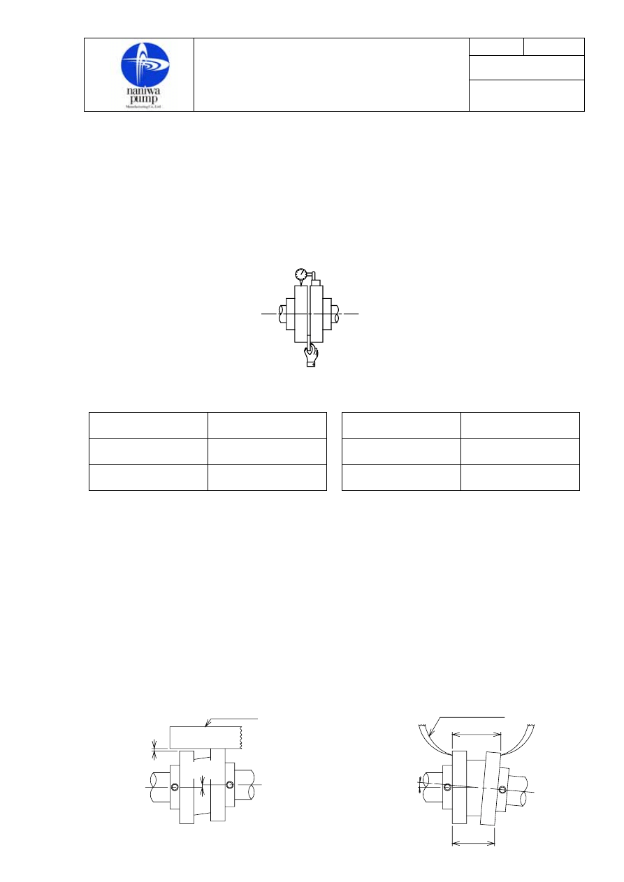
8-2. Checking of alignment
a. Untighten the bolts of the shaft coupling between pump and motor and check the alignment at four
points, 90°apart, on the coupling periphery.
b. For comparing the distance between the faces, fix a dial indicator on the shaft coupling of the motor
side as shown in Fig.1 (a) and give the motor coupling one complete rotation by hand. Then half of the
variation in readings is taken as the value of measurement, which must comply with the value in Table
1.
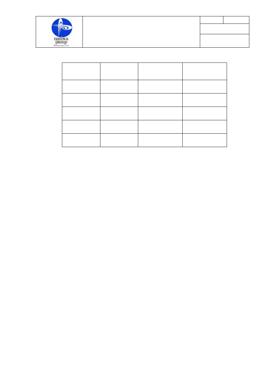
Table .1 Table .2
No. of motor frame
Coupling periphery
(mm)
No. of motor frame
Coupling end face
(mm)
M180L(ML5-180L)
and less
0.05 and less
M132M(ML5-132M)
and less
0.10 and less
M200M(ML5-200M)
and more
0.08 and less
M160M(ML5-160M)
and more
0.18 and less
c. For measuring the clearance between coupling faces, insert a thickness gauge at four points of equal
interval as shown in Fig.1 (b). Then the value of measurement, which must comply with the value in
Table 2.
d. Ensure the rotating direction of the motor.
e. Tighten the coupling bolts.
f. Rotate the pump by hand to see whether it rotates smoothly.
Note : A thickness gauge should be adopted for alignment only at the times of repair, intermediate inspection and
periodical inspection. It is preferable to use a dial indicator for checkup after initial installation or piping
arrangement.
【
FOR SURE FLEX COUPLING
】
* Use straight edge or a caliper (pass) as shown in Fig.1 or Fig.2.
* Adjust alignment to comply with the values shown in table 1.
* Confirm motor rotating direction and that pump turns smoothly by hands.
Pump end
(b)
(a)
Fig.1
Motor end
B
B
1
2
A
Eccentric
Eccentric
angle
Strate edge
Caliper(Pass)
Fig. 1.
Fig. 2.
Page
6
of
12
No.3-1A
INSTRUCTION MANUAL
FOR
MOTOR DRIVEN GEAR PUMPS
Date:
15 March 2000
COUPLING
SIZE
MOTOR
FRAME NO.
ERRORS OF
ECCENTRICITY
A mm
ERRORS OF
ANGULARITY
B1-B2 mm
3S
63
71
0.25 0.45
4S
80
90L
0.25 0.55
5S
100L
112M
0.38 0.7
6S
132S
132M
0.38 0.9
7S 160M 0.51
1.0
9. Operation
Operation after installation or reassemble must be carried out in the following order.
9-1 Preparation before Operation
a. Fully open the valves of both suction and discharge sides.
b. Open the air vent valve (or cock) on the casing top to fill the casing with liquid.
c. If the pump is located above the suction level, pull the plug out of the casing top and fill the casing
with oil while rotating the pump by hand in order to fully spread oil over the teeth and the bearings.
Keep the air vent plug (or cock) on the discharge side open.
d. See that the cock (or plug) of the pressure gauge and compound gauge is open.
e. Rotate the pump by hand to see whether it turns smoothly.
9-2 Operation
a. Start the motor, but at first repeat “ON” and “OFF” operations once or twice and enter into operation
on confirming that there is no abnormal condition with respect to rotating direction, noise, vibration,
starting current, etc.
b. Tighten the air vent plug (or cock) after speed has risen, and air is discharged from the air vent and
liquid is pumped up in some time. If liquid is not pumped up in about 30 seconds after start-up, stop
the motor and check the cause.
c. Avoid dry operation absolutely as the sliding contact surfaces of the bearings, the teeth and the
mechanical seal are of self-lubrication construction.
d. Pay a careful attention in the winter season because there may be a fear of excessive torque of motor
and abnormal noise and vibration of pump caused by oil viscosity increase. Some treatment such as
heating is preferable.

Page
7
of
12
No.3-1A
INSTRUCTION MANUAL
FOR
MOTOR DRIVEN GEAR PUMPS
Date:
15 March 2000
9-3 Stopping
a. Stop the motor.
b. After stopping the pump, close the suction valve and then close the discharge valve.
10. Maintenance
In order to maintain an efficient operation over a long period, the utmost care must be taken.
10-1 Cautions during Operation
a. Try to operate the pump within the range of the design condition.
b. Check the vibration, noise, pressure gauge and ammeter. If abnormal condition is surveyed stop the
pump immediately. Particularly, for the pump provided with a mechanical seal, protect against
vibration in view of the service life of the mechanical seal.
c. Pay attention to bearing temperature rise. If the bearing housing can be felt by hand safely, there is no
fear, otherwise, measure the temperature with a thermometer. Keep the permissible bearing temperature
at “ambient temperature plus 40℃” or “liquid temperature plus 20℃”. If low viscosity oil outside the
range of design condition, be careful as the bearings and the gear may be seized.
d. Keep a small amount of continuous leak from the gland. Too hard tightening of the packing will cause
premature wear of the shaft and the sleeve, overheating and overload. Especially pay a careful attention
to a case where oil of high temperature or low viscosity is used.
e. When a mechanical seal is used, oil leak is generally very small. If oil leaks in drips, check the seal.
f. Never throttle the valve on the suction and discharge sides. Adjust the flow by means of the by-pass
valve on the discharge side.
g. Never operate with the valve closed on the discharge side, otherwise a temperature rise of the liquid in
the casing will cause seizure.
h. See whether the stand by pump is reversing due to the leakage from its non return valve.
i. In the case of a pump with automatic starting and stopping device, check the pressure at the start and
stop of pump as well as the interval of operation, and if the interval is too short, check the system.
j. In the case of automatic operation under central control system, take care of the indication of gauge on
the control panel board.
k. Keep the strainer clean to avoid clogging.
Page
8
of
12
No.3-1A
INSTRUCTION MANUAL
FOR
MOTOR DRIVEN GEAR PUMPS
Date:
15 March 2000
10-2 Cautions during Standstill
a. Keep closed the discharge and suction valves. But such valves must be kept open in a case where the
pump is of auto start type with a foot valve or a check valve, where the pump is under positive suction
head or where oil is accumulated in the pump casing in some way or other.
b. When the pump is shut down over a long period, the pump must be rotated by hand or motor
periodically. (once a week or so)
11. Inspection
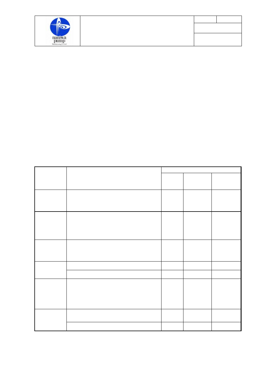
11-1 Periodical Inspection
Excepting the case of abnormal conditions, it is desirable to carry out inspection periodically in the
following way, but since it varies according to the method of mounting, place of installation, liquid
handled, etc. It is preferable that the operator should make a final plan of inspection in accordance with
conditions.
Period
Item
Action to be taken
Every 3
months
Every 12
months or
8,000 hrs.
Every 4
years or
20,000 hrs.
Ball bearing
Check up inner and outer races as well as balls
for exfoliation, and if its trance is found, renew
it.
○
Line bearing
Check up sliding surfaces for conditions
of contact and flaw. Measure inside
diameter and take necessary steps
according to manufacture’s
recommendation.
○
Gland
Packing
Check up condition of fitting and amount
of leakage. Renew it if leakage is too
much.
○
Check up condition of mating faces.
○
Mechanical
seal
Renew it.
○
Shaft
Check up conditions of contact, flaw in
sliding faces. Measure the outside
diameter of journal and treat it
according to manufacturer’s
recommendation.
○
Check up surface flaw and condition of
deterioration. Renew it if deformed.
○
“O” ring
Renew it.
○
Page
9
of
12
No.3-1A
INSTRUCTION MANUAL
FOR
MOTOR DRIVEN GEAR PUMPS
Date:
15 March 2000
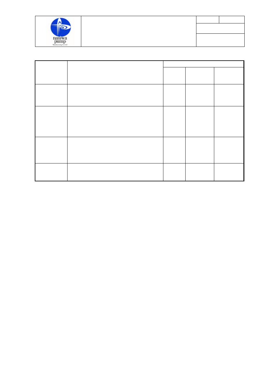
Period
Item
Action to be taken
Every 3
months
Every 12
months or
8,000 hrs.
Every 4
years or
20,000 hrs.
Safety Valve
Throttle the discharge valve to raise
discharge pressure and confirm
operation of the safety valve
○
Gear
Check up tooth surfaces and condition of
its setting to the shaft. Measure the
outside diameter and width and treat it
according to manufacturer’s
recommendation
○
Shaft
coupling bolts
and
rubber rings
Check up conditions of wear and renew
them if abnormal points are found.
○
Foundation
bolts
See to it that the foundation bolts are
tightened enough.
○
Note : The hours quoted refer to the operating hours.
11-2 Overhaul
When overhauling the pump, attention must be paid as follows.
a. Understand the construction well by referring to the assembly drawing and make no mistake in the
order of overhaul.
b. When separating fit and flange faces, use jack bolts and wooden hammers, and never apply force with
chisels or drivers.
c. When removing the rotating element, take care to avoid flaw on sliding faces and machined surfaces.
It is preferable not to overhaul the mechanical seal unless there is anything abnormal.
d. When removing rotating parts from the shaft, draw off each one carefully after removing the locking
device.
e. Handle the longsized-parts such as shaft carefully so that it may not bend.
f. Handle the parts carefully, by arranging them on sheets of paper or cloth in good order.
g. At overhauling, put suitable match marks as many as possible to avoid mistakes when reassembling.

Page
10
of
12
No.3-1A
INSTRUCTION MANUAL
FOR
MOTOR DRIVEN GEAR PUMPS
Date:
15 March 2000
11-3 Assembly
Carry out assembly, by reversing the order of disassembly and paying attention as follows.
a. Remove dust and stain from each part by washing it thoroughly with kerosene.
Repair it if flaw is found.
b. Fit the locking device perfectly in each rotating part if necessary.
c. When fitting the parts with match marks such as fittings and gear, be sure to follow them.
d. Before assembling the sliding contact faces of the bearings, tooth faces and mechanical seal, apply
enough clean lube oil to them.
e. When fitting the bearings and side cover, take into account the position of oil channel for bearing lube
oil and return oil and the direction of pump discharge and suction.
f. Insert each packing in good order softly one by one from the bottom, staggering each joint by 90°or
180°to a fixed position and support it lightly with the packing gland.
g. Carefully fit the mechanical seal and then confirm its movement by hand.
h. Tighten the bolts with an equal force.
i. Check up the alignment as mentioned in Section 8.
j. Rotate the pump by hand to see that it turns smoothly.
Page
11
of
12
No.3-1A
INSTRUCTION MANUAL
FOR
MOTOR DRIVEN GEAR PUMPS
Date:
15 March 2000
12.Troubles and Remedies
Should troubles occur, their causes must be traced and necessary remedies must be carried out. The
following, for instance, can be conceivable as troubles.
Troubles Causes
Remedies
Pump does
not start.
・Motor is in trouble.
・Pump seizes.
・No power source.
・Wiring is broken, or relay, etc.
are in trouble.
・Foreign matters exist in the pump.
・Repair motor.
・Repair pump.
・Check up electric system.
・Repair
・Overhaul the pump and remove
them.
Pump starts,
but does not
discharge
liquid.
・Pump is not well filled with oil.
・Air is not vented enough.
・Valves are not open.
・Valves will not open.
・Pump is sucking air.
・Suction pipe or strainer is clogged.
・Motor rotating direction is wrong.
・Fill it again.
・Open air plug (or cock)
・Open valves.
・Repair valves.
・Check up suction system and
gland packing
・Clean suction pipe or strainer.
・Change wiring.
Pump starts,
but specified
capacity or
discharge
pressure are
not reached.
・Pump is sucking air.
・Pump speed are too low.
・Safety valve is open.
・Suction pipe or strainer is clogged.
・Liquid viscosity is too low.
・Gear shaft is worn.
・Suction pressure is too high.
・Instruments are wrong.
・Check up suction system and
gland packing
・Correct electric source.
・Adjust its setting.
・Clean it.
・Check design specification.
・Renew it.
・Check viscosity.
・Suction Pressure shall be within
-380mmHg.
・Confirm full opening of suction
valve.
・Replace them with new ones.
Pump starts
and
discharges
liquid but
soon ceases to
discharge
liquid.
・Air pockets exist in suction line.
・Pump is sucking air.
・Pump is sucking air through
stuffing box.
・Correct piping.
・Check up suction system.
・Check up sealing pipe
・Adjust mechanical seal.
・Adjust packing.
Page
12
of
12
No.3-1A
INSTRUCTION MANUAL
FOR
MOTOR DRIVEN GEAR PUMPS
Date:
15 March 2000
Troubles Causes
Remedies
Pump starts,
but
motor gets
overloaded.
・Abnormal metal contact exists in
the rotating parts.
・Connection is wrong.
・Packing is too tightened.
・Pump shaft is bent.
・Motor is in trouble.
・Liquid viscosity is too high.
・Foreign matters exist in the pump.
・Discharge pressure is too high.
・Bearings are wrong.
・Check clearance.
・Check up alignment.
・Loosen gland or otherwise renew
packing
・Renew shaft.
・Repair it.
・Conform it to design condition.
・Remove them.
・Conform it to design condition.
・Renew them.
Pump starts,
but bearings
get
overheated.
・Lubricant is in shortage.
・Connection is wrong.
・Bearings are wrong.
・Shaft is bent.
・Thrust has increased.
・Bearing assembly is wrong.
・Check oil supply to bearings and
return oil system.
・Check up alignment.
・Renew them.
・Renew it.
・Check whether excessive wear
exists on bearing side or whether
pump is in abnormal suction
pressure condition.
・Readjust bearings.
Pump starts,
but vibration
and accidental
noise takes
place.
・Connecting is wrong.
・Shaft is bent.
・Installation is wrong.
・Foundation is weak.
・Other vibration is transmitted.
・Cavitation exists.
・Bearings are worn.
・Safety valve is chattering.
・Foreign matters exist in the pump.
・Tooth contact is wrong.
・Check up alignment.
・Renew shaft.
・Correct installation condition.
・Reinforce foundation.
・Reinforce piping.
・Conform suction pressure and
viscosity to design condition.
・Renew them.
・Repair it
・Overhaul the pump to remove
them.
・Renew the gear.
In case troubles cannot be remedied in spite of the above counter-measures, the causes may
be in the design conditions of the pump, so it is preferable to consult the shipyard or manufacturer.
Wyszukiwarka
Podobne podstrony:
10 INSTRUCTION MANUAL WATER PUMP 12146 3045 E
06 INSTRUCTION MANUAL FUEL OIL FILTER 12153 3188 E
07 INSTRUCTION MANUAL LUB OIL FILTER 12153 3204
DJ F1 S1 Instruction Manual
Instrukca obsl ELECTRA(Piłat-korekta 26 09), Instrukcje w wersji elektronicznej
09 Instrukcja obsługi BFC
JS 09 Instrukcja switch, Programowanie, instrukcje - teoria
BSA Instruction Manual D14
13-OBSŁ. MŁYNKA DO TARTEJ BUŁKI TYP - ZM 09, Instrukcje BHP, XX - PIEKARNICTWO I CUKIERNICTWO
Instruction Manual
Id 09 Instrukcja dla toromistrza
Instrukcja gospodarki gazem SF6 w urządzeniach elektroenergetycznych, Instrukcja SF6 po poprawkach 1
ICOM instruction manual[1]
cw 09 instrukcja
DJ F1 S1 Instruction Manual
Instrukca obsl ELECTRA(Piłat-korekta 26 09), Instrukcje w wersji elektronicznej
MALOWANIE LINJI easylineedge instruction manual
Instrukcja (manual) wymiany linek hamulca ręcznego (pomocniczego, awaryjnego) fiat punto I (1,1)
102003BGA Reballing Instruction Manual
więcej podobnych podstron