Engine (211348)
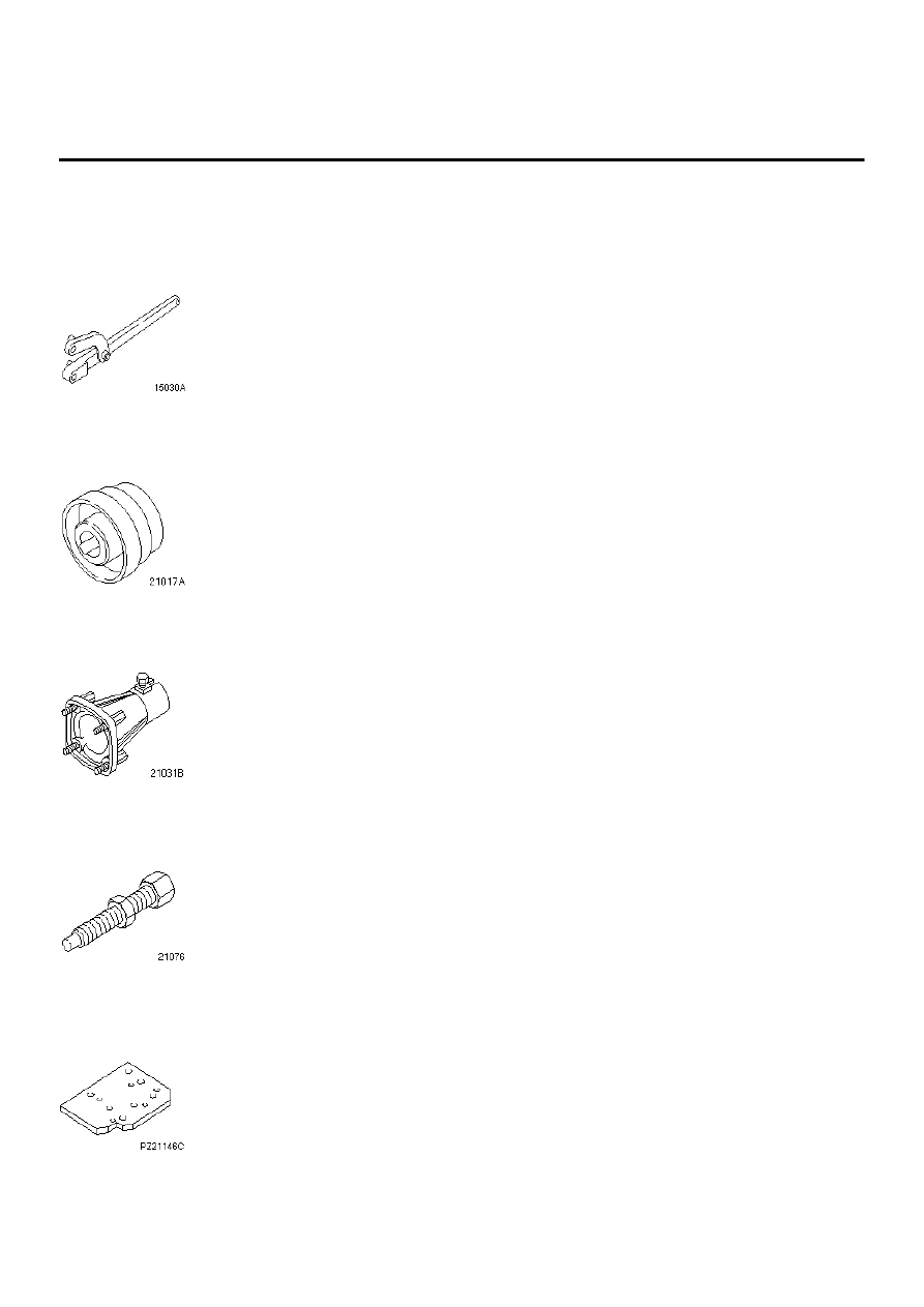
Special Service Tool(s)
Universal flange holding wrench
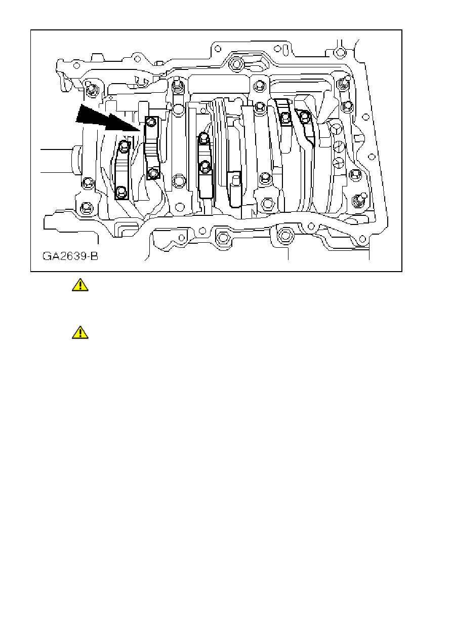
205-072 (15-030A)
Oil seal installer and aligner
303-055 (21-017A)
Mounting bracket
303-435-06 (21-031B)
Remover and installer, vibration damper
303-130 (21-076)
Mounting plate
303-435-11 (21-146C)
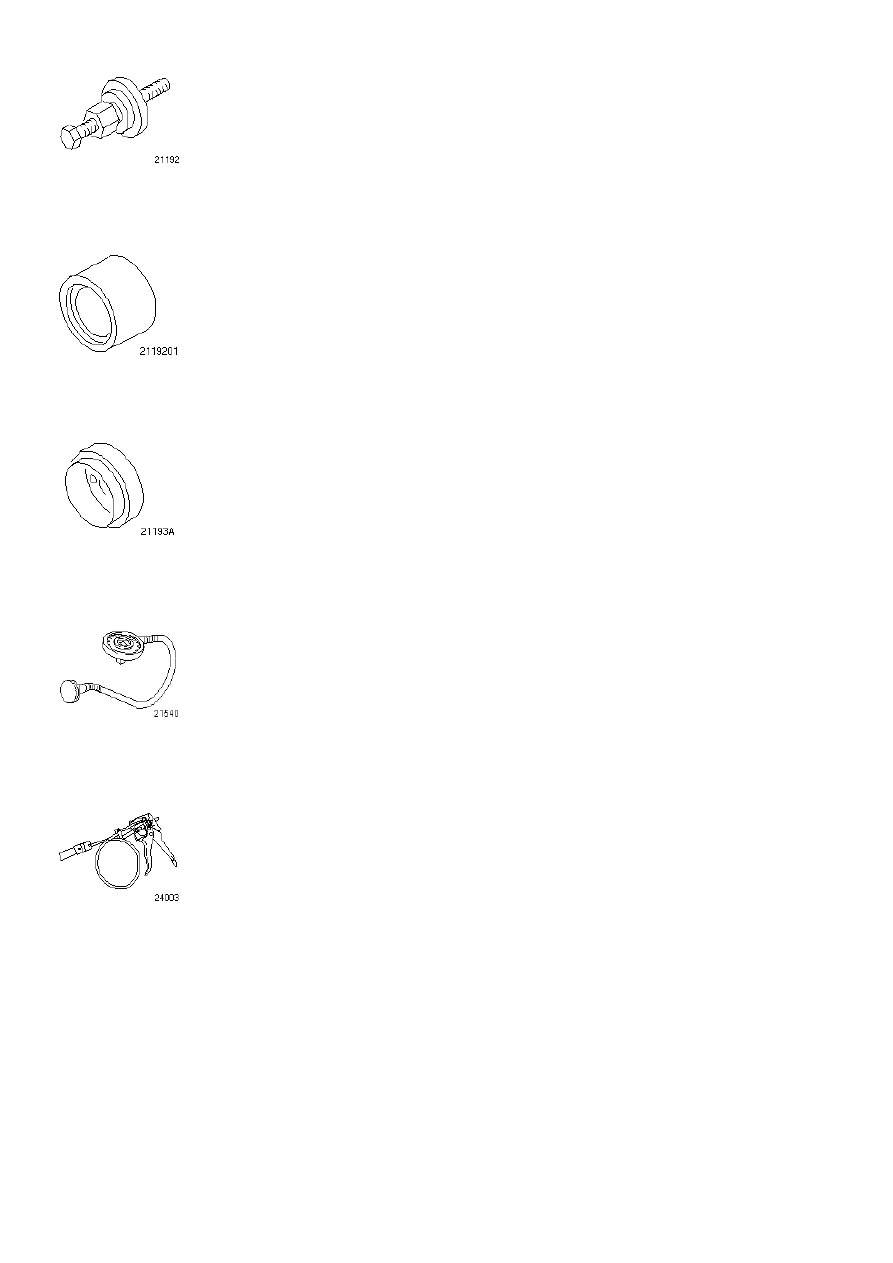
Installer, camshaft pulley
303-458 (21-192)
Adapter, oil seal installation
303-458-01 (21-192-01)
Installer, crankshaft rear oil seal
303-460 (21-193A)
Angle gauge, bolt tightening
303-174 (21-540)
Radiator hose clamp remover/installer
303-397 (24-003)
General Equipment
⁄ƒƒƒƒƒƒƒƒƒƒƒƒƒƒƒƒƒƒƒƒƒƒƒƒƒƒƒƒƒƒƒƒƒƒƒƒƒƒƒƒƒƒƒƒƒƒƒƒƒƒƒƒƒƒƒƒƒƒƒƒƒƒƒƒø
≥ Assembly stand ≥
¿ƒƒƒƒƒƒƒƒƒƒƒƒƒƒƒƒƒƒƒƒƒƒƒƒƒƒƒƒƒƒƒƒƒƒƒƒƒƒƒƒƒƒƒƒƒƒƒƒƒƒƒƒƒƒƒƒƒƒƒƒƒƒƒƒŸ
Materials
⁄ƒƒƒƒƒƒƒƒƒƒƒƒƒƒƒƒƒƒƒƒ¬ƒƒƒƒƒƒƒƒƒƒƒƒƒƒƒƒƒƒƒƒ¬ƒƒƒƒƒƒƒƒƒƒƒƒƒƒƒƒƒƒƒƒø
≥ Lubricant, O-rings ≥ ESD-M97B49-A ≥ ≥
√ƒƒƒƒƒƒƒƒƒƒƒƒƒƒƒƒƒƒƒƒ≈ƒƒƒƒƒƒƒƒƒƒƒƒƒƒƒƒƒƒƒƒ≈ƒƒƒƒƒƒƒƒƒƒƒƒƒƒƒƒƒƒƒƒ¥
≥ Lubricant, spark ≥ ESE-M1244-A (Never ≥ ≥
≥ plugs ≥ Seeze) ≥ ≥
√ƒƒƒƒƒƒƒƒƒƒƒƒƒƒƒƒƒƒƒƒ≈ƒƒƒƒƒƒƒƒƒƒƒƒƒƒƒƒƒƒƒƒ≈ƒƒƒƒƒƒƒƒƒƒƒƒƒƒƒƒƒƒƒƒ¥
≥ Sealer, flywheel ≥ SDM-M4G9107-A ≥ ≥
√ƒƒƒƒƒƒƒƒƒƒƒƒƒƒƒƒƒƒƒƒ≈ƒƒƒƒƒƒƒƒƒƒƒƒƒƒƒƒƒƒƒƒ≈ƒƒƒƒƒƒƒƒƒƒƒƒƒƒƒƒƒƒƒƒ¥
≥ Sealer, oil ≥ SM-4G-4644-AA/AB ≥ ≥
≥ /coolant passages ≥ ≥ ≥
√ƒƒƒƒƒƒƒƒƒƒƒƒƒƒƒƒƒƒƒƒ≈ƒƒƒƒƒƒƒƒƒƒƒƒƒƒƒƒƒƒƒƒ≈ƒƒƒƒƒƒƒƒƒƒƒƒƒƒƒƒƒƒƒƒ¥
≥ Lubricant, ≥ SQM-2C9002-AA ≥ ≥
≥ camshaft bearings ≥ ≥ ≥
√ƒƒƒƒƒƒƒƒƒƒƒƒƒƒƒƒƒƒƒƒ≈ƒƒƒƒƒƒƒƒƒƒƒƒƒƒƒƒƒƒƒƒ≈ƒƒƒƒƒƒƒƒƒƒƒƒƒƒƒƒƒƒƒƒ¥
≥ Sealer, cylinder ≥ WSK-M4G320-A ≥ ≥
≥ block ≥ ≥ ≥
√ƒƒƒƒƒƒƒƒƒƒƒƒƒƒƒƒƒƒƒƒ≈ƒƒƒƒƒƒƒƒƒƒƒƒƒƒƒƒƒƒƒƒ≈ƒƒƒƒƒƒƒƒƒƒƒƒƒƒƒƒƒƒƒƒ¥
≥ Engine oil ≥ WSS-M2C912-A1 ≥ ≥
¿ƒƒƒƒƒƒƒƒƒƒƒƒƒƒƒƒƒƒƒƒ¡ƒƒƒƒƒƒƒƒƒƒƒƒƒƒƒƒƒƒƒƒ¡ƒƒƒƒƒƒƒƒƒƒƒƒƒƒƒƒƒƒƒƒŸ
Assembly
1.
CAUTION:
Only use a plastic scraper when removing old gasket material.
Thoroughly clean all mating faces and reusable parts and check them for damage.
2.
Note:
Do not remove the blanking plugs or alignment dowels unless they are being renewed.
Reseal the oil passage blanking plugs as necessary.
z
Use oil/coolant passage sealer.
µ
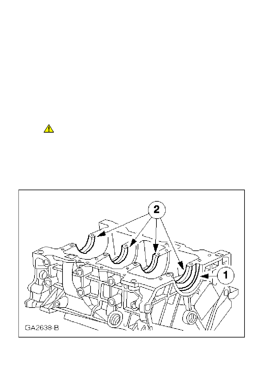
3.
Note:
The main bearings are precision fit parts. Check the bearing clearance. For additional
information, refer to
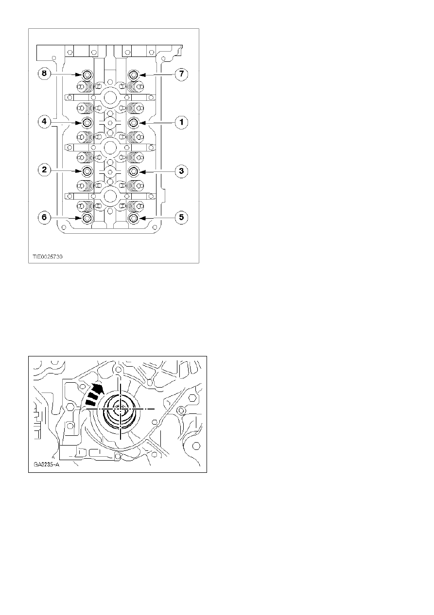
«Section 303-00»
.
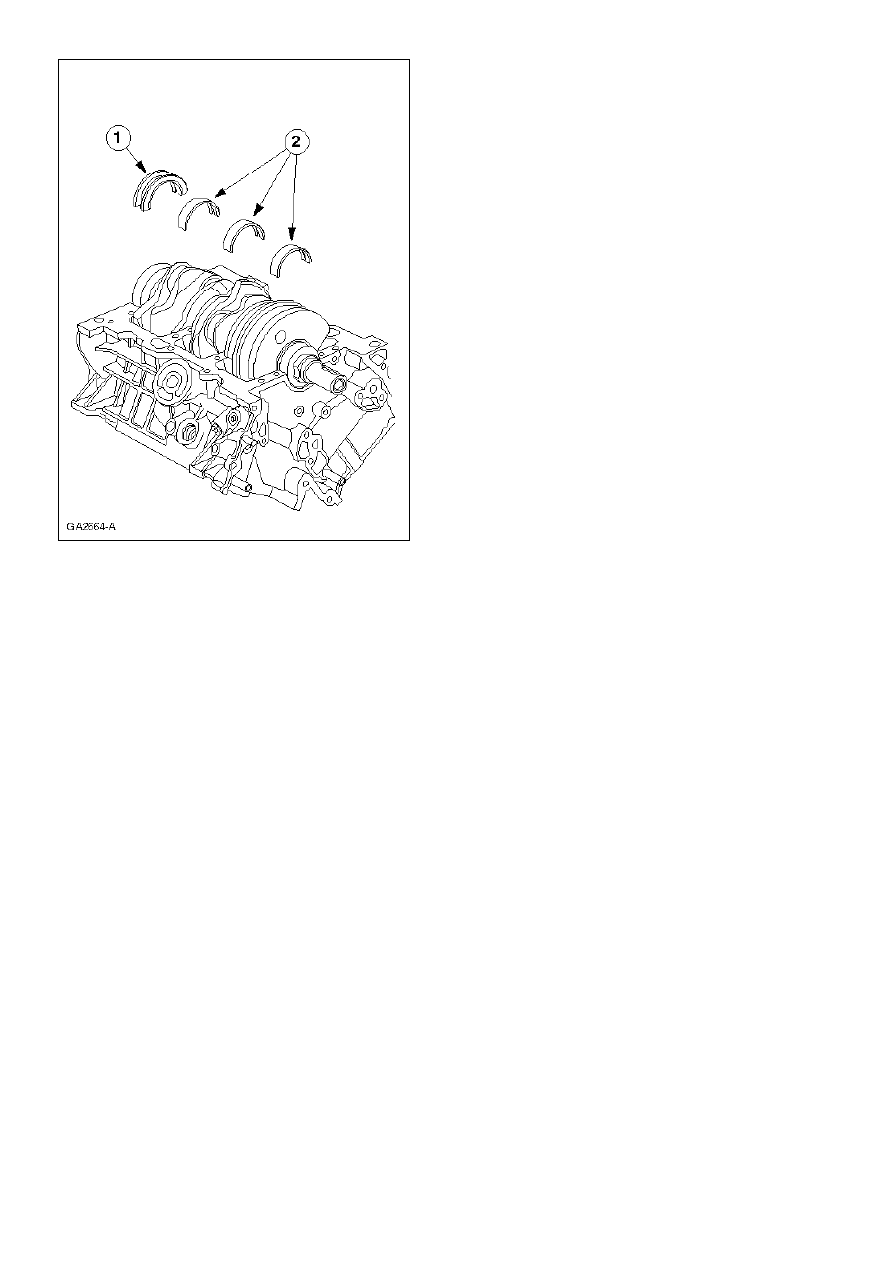
Install the upper main bearing shells and the thrust half ring.
1
Thrust half ring
2
Upper main bearing shells
z
Coat the main bearing shells and thrust half ring with engine oil.
µ
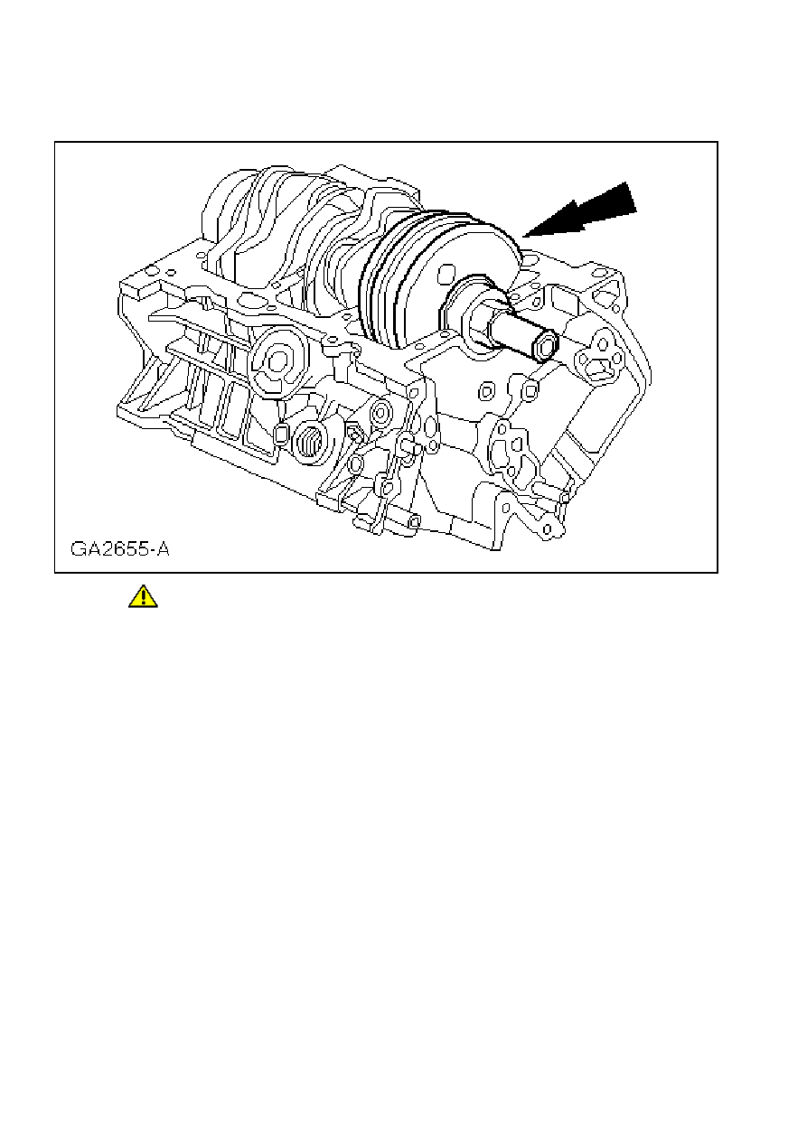
4.
CAUTION:
Avoid damage to the crankshaft bearing journal surfaces.
Install the crankshaft.
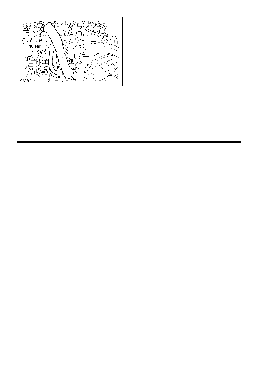
µ
5.
Note:
Press the crankshaft back before inserting the main bearing shells.
Note:
Align the oil bores on the bearing shells and the cylinder block.
Note:
Align the assembly lug on the bearing shells with the mating face of the cylinder block.
Install the lower main bearing shells.
1
Crankshaft thrust main bearing shell.
2
Lower main bearing shells.
z
Coat the main bearing shells and the thrust main bearing shell with engine oil.
6.
Clean the lower and upper cylinder block mating faces before beginning assembly.
µ
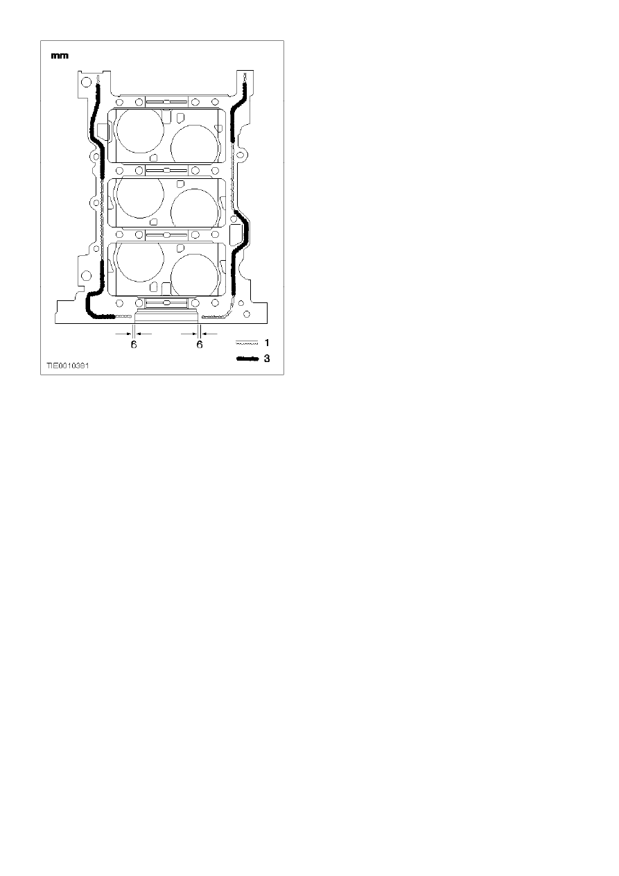
7.
Note:
The bolts must be tightened within 4 minutes of applying the sealer.
Apply a bead of sealer to the cylinder block.
z
Apply cylinder block sealer on both sides up to a distance of 6 mm from the rear
crankshaft bore.
z
Apply a 3 mm bead of sealer to the indicated areas.
z
Apply a 1 mm bead of sealer to the indicated areas.
µ
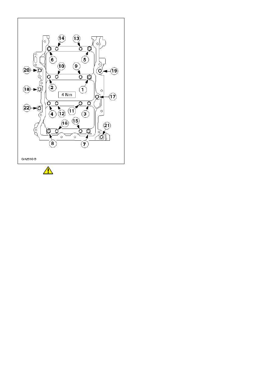
8.
CAUTION:
Check the installation position of all locating dowels in the lower crankcase.
Note:
The bolts must be tightened within 4 minutes of applying the sealer.
Note:
Do not lubricate the lower crankcase bolts.
Note:
Tightening sequence.
Attach the lower crankcase to the cylinder block.
z
Push the crankshaft rearward and insert the thrust half ring.
µ
9.
CAUTION:
Bolts 1 to 16 are torque-to-yield bolts and must be renewed.
Note:
Different torques.
Note:
Tightening sequence.
Tighten the bolts in four stages.
z
Bolts 1 - 8, 25 Nm
z
Bolts 9 - 16, 40 Nm
z
Bolts 1 - 16, 90 degrees
z
Bolts 17 - 22, 25 Nm
z
Check that the crankshaft rotates freely.
10.
Remove any protruding sealer residue.
11.
CAUTION:
Protect the surfaces of the crankshaft bearing journals and the cylinder bore from
damage.
Place the crankshaft with the main bearing journal in the BDC position.
12.
Note:
Install the piston with the arrow pointing to the front of the engine.
Compress the piston rings and install the piston and the connecting rod.
z
Coat all piston components with engine oil.
µ
13.
CAUTION:
When assembling the connecting rods and connecting rod bearing caps, it is imperative
that the bearing slots and lugs are located on the same side of the connecting rod.
CAUTION:
The connecting rod bolts are torque-to-yield bolts and must be renewed.
Fit the connecting rod bearing cap to the appropriate connecting rod and alternately tighten the
bolts in three stages as indicated.
z
Stage 1: 23 Nm
z
Stage 2: 43 Nm
z
Stage 3: 90 degrees
14.
Check the connecting rod axial clearance. For additional information, refer to
«Section 303-00»
.
15.
Rotate the crankshaft to check that it can turn freely.
µ
16.
Note:
Tightening sequence.
Install the oil pump.
µ
17.
Install the oil pan baffle.
z
Tighten the nuts in two stages.
z
Stage 1: 5 Nm
z
Stage 2: 45 degrees
µ
18.
Note:
Apply O-ring lubricant to the O-ring before installation.
Install the oil pick-up pipe retaining nut.
z
Tighten the nut in two stages.
z
Stage 1: 5 Nm
z
Stage 2: 45 degrees
µ
19.
Install the oil pick-up pipe retaining bolts.
µ
20.
Note:
Install a new oil separator gasket.
Install the oil separator.
µ
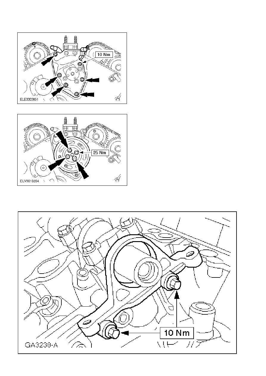
21.
Install the bracket for the power steering pump.
z
Align the bracket with the locating sleeves.
µ
22.
Note:
Install a new cylinder head gasket.
Note:
Left-hand and right-hand cylinder head gaskets are not interchangeable.
Note:
Install a new cylinder head bolts with washers.
Install the left-hand cylinder head.
z
Align the cylinder head with the locating dowels.
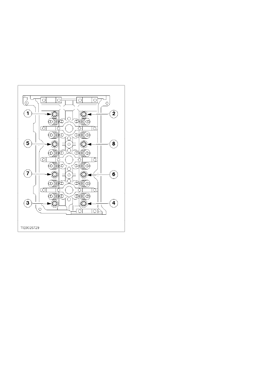
z
Tighten the bolts in the sequence shown in two stages..
z
Stage 1: 40 Nm
z
Stage 2: 90 degrees
µ
23.
Loosen the left-hand cylinder head bolts.
z
Loosen the bolts in the sequence shown one turn.
µ
24.
Tighten the left-hand cylinder head bolts in the sequence shown in three stages..
z
Stage 1: 40 Nm
z
Stage 2: 90 degrees
z
Stage 3: 90 degrees
µ
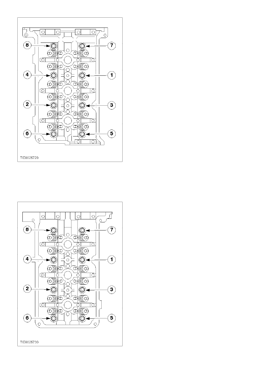
25.
Note:
Install new cylinder head gasket.
Note:
Left-hand and right-hand cylinder head gaskets are not interchangeable.
Note:
Install new cylinder head bolts with washers.
Install the right-hand cylinder head.
z
Align the cylinder head with the locating dowels.
z
Tighten the bolts in the sequence shown in two stages.
z
Stage 1: 40 Nm
z
Stage 2: 90 degrees
µ
26.
Loosen the right-hand cylinder head bolts.
z
Loosen the bolts in the sequence shwon one turn.
µ
27.
Tighten the right-hand cylinder head bolts in the sequence shown in three stages.
z
Stage 1: 40 Nm
z
Stage 2: 90 degrees
z
Stage 3: 90 degrees
28.
Check all the camshafts in accordance with the specifications. For additional information, refer
to
«Section 303-00»
.
µ
29.
Position the crankshaft for installation of the left-hand timing chain.
z
Install the washer and the bolt on the crankshaft pulley/vibration damper.
z
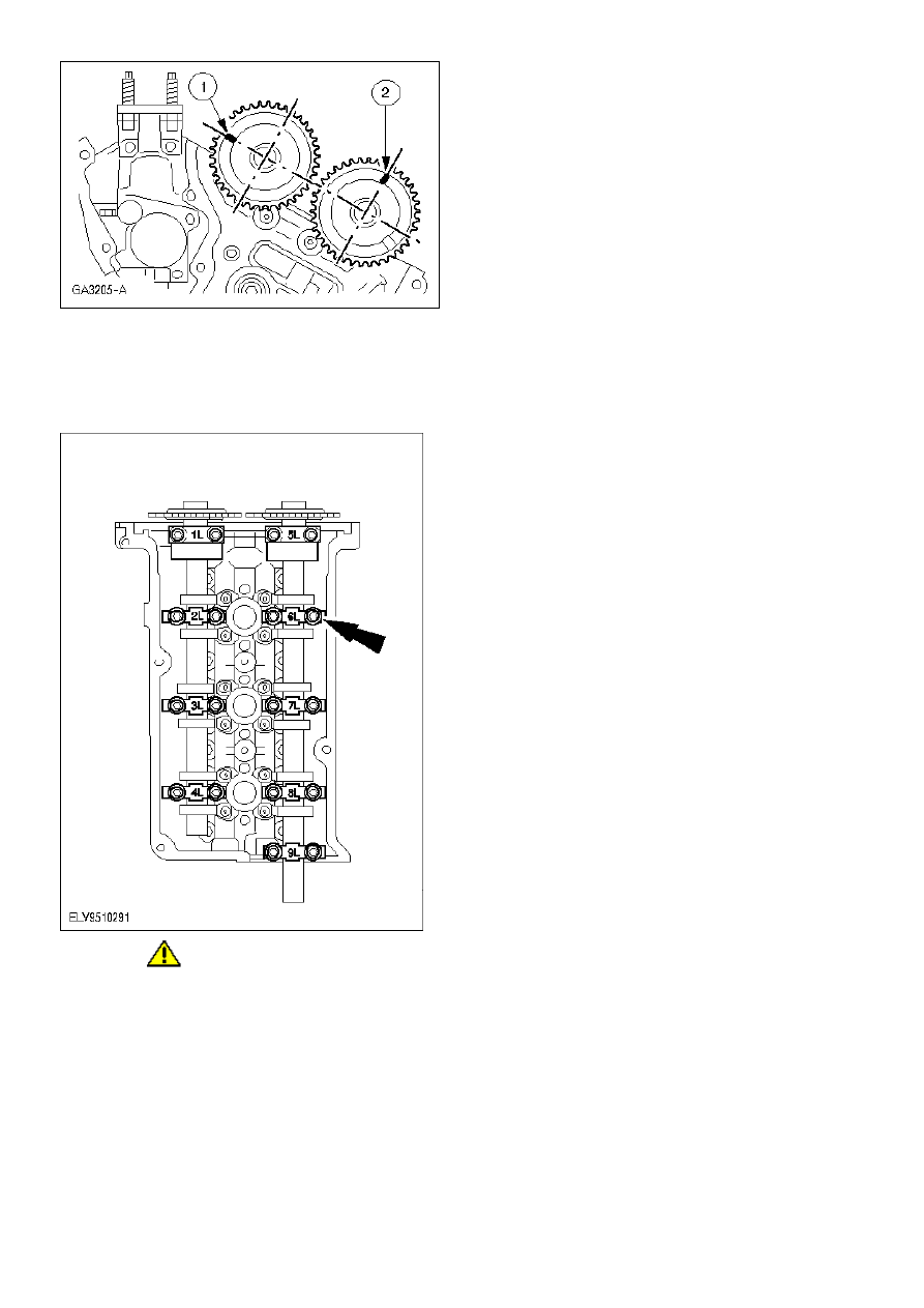
Turn the crankshaft clockwise until the Woodruff key is in the 11 o'clock position.
30.
Install the valve tappets.
z
Coat the tappets with camshaft bearing lubricant prior to installation.
µ
31.
Install the camshafts on the left-hand cylinder head and align them with the top edge of the
cylinder head.
1
Position the marking on the intake camshaft to the 9 o'clock position.
2
Position the marking on the exhaust camshaft to the 12 o'clock position.
µ
32.
CAUTION:
Install the thrust bearing caps (1L and 5L) last.
Note:
Do not tighten the bolts.
Install the bearing caps of the left-hand camshaft.
z
Use camshaft bearing lubricant.
µ
33.
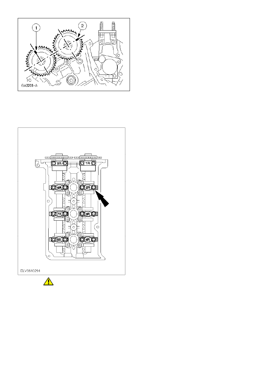
Install the camshafts on the right-hand cylinder head and align them with the top edge of the
cylinder head.
1
Position the mark on the exhaust camshaft to the 12 o'clock position.
2
Position the mark on the intake camshaft to the 3 o'clock position.
µ
34.
CAUTION:
Install the thrust bearing caps (1R and 5R) last.
Note:
Do not tighten the bolts at this stage.
Install the bearing caps of the right-hand camshaft.
z
Use camshaft bearing lubricant.
35.
Remove the crankshaft pulley/vibration damper bolt.
µ
36.
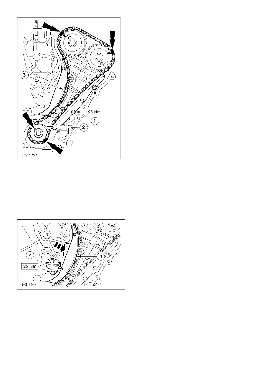
Note:
The copper links of the timing chain and the marks on the timing chain sprockets must line up.
Install the left-hand timing chain.
1
Install the timing chain guide (black material).
2
Push on the crankshaft timing chain sprocket. The mark for adjusting the valve timing
must face towards the front.
3
Install the timing chain.
µ
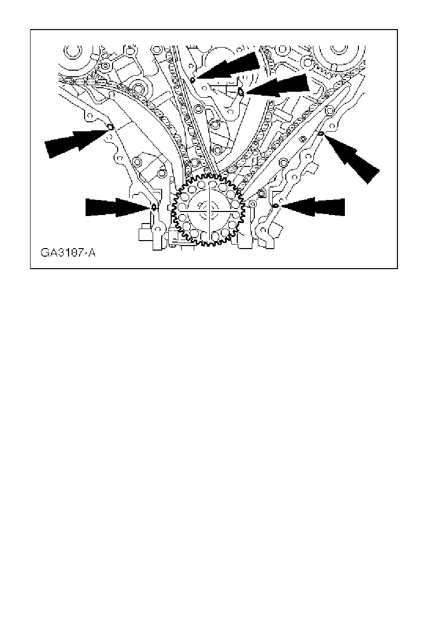
37.
Install the left-hand timing chain tensioner and left-hand timing chain guide.
1
Install the timing chain guide.
2
Install the pre-tensioned timing chain tensioner and the adapter plate (if removed).
3
Tighten the timing chain by applying pressure to the timing chain guide, and pull the wire
out of the timing chain tensioner.
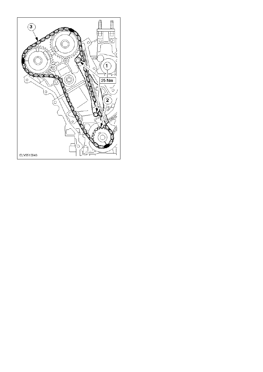
µ
38.
Note:
The copper links of the timing chain and the marks on the timing chain sprockets must line up.
Install the right-hand timing chain.
1
Install the timing chain guide (beige mounting).
2
Push on the crankshaft timing chain sprocket. The mark for adjustment of the valve timing
must face towards the front.
3
Install the timing chain.
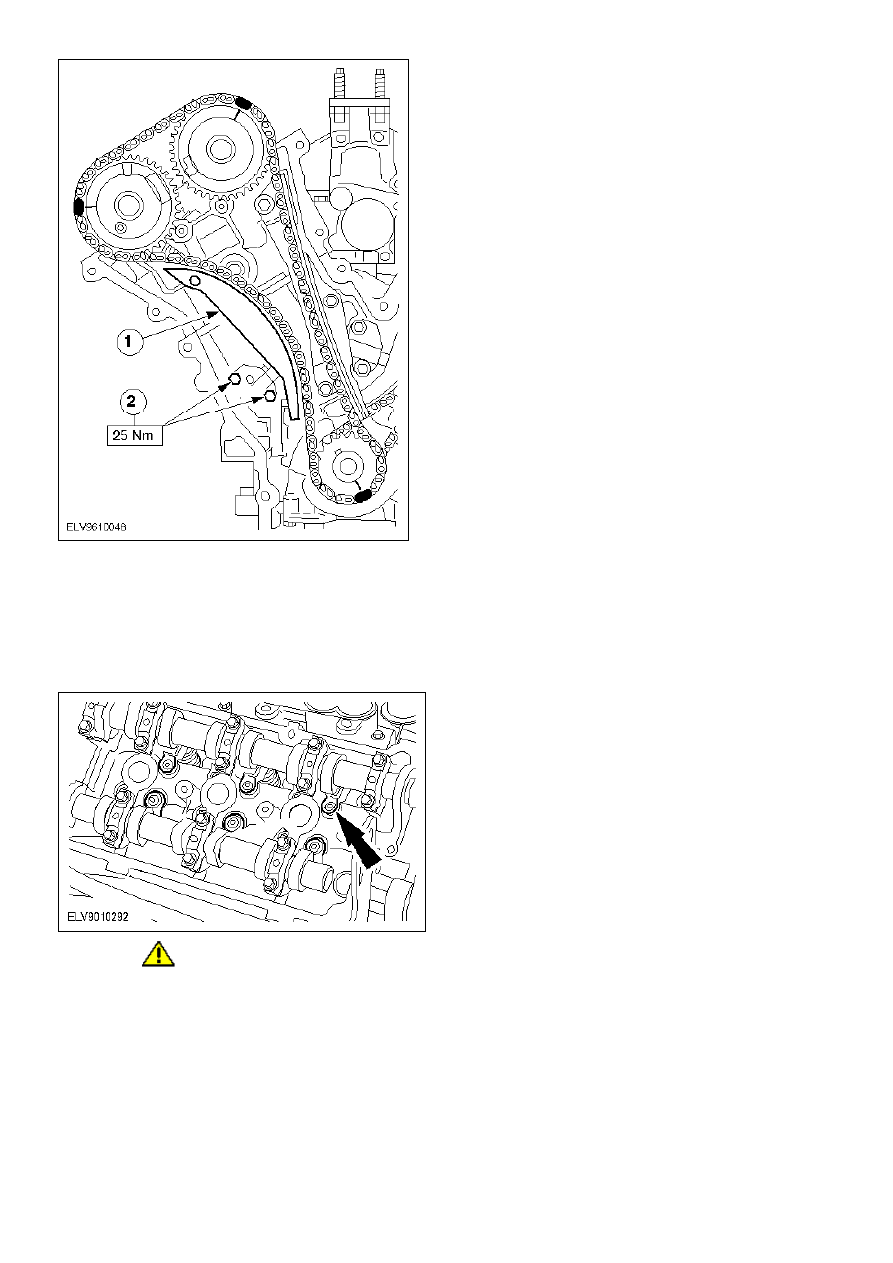
µ
39.
Install the right-hand timing chain tensioner.
1
Install the timing chain guide.
2
Install the pre-tensioned timing chain tensioner and the adapter plate (if removed).
z
Tighten the timing chain by applying pressure to the timing chain guide, and pull the wire
out of the timing chain tensioner.
µ
40.
CAUTION:
Crankshaft Woodruff key at 11 o'clock position.
Install the cam followers on the left-hand cylinder head.
z
Use camshaft bearing lubricant.
µ
41.
Note:
Tightening sequence.
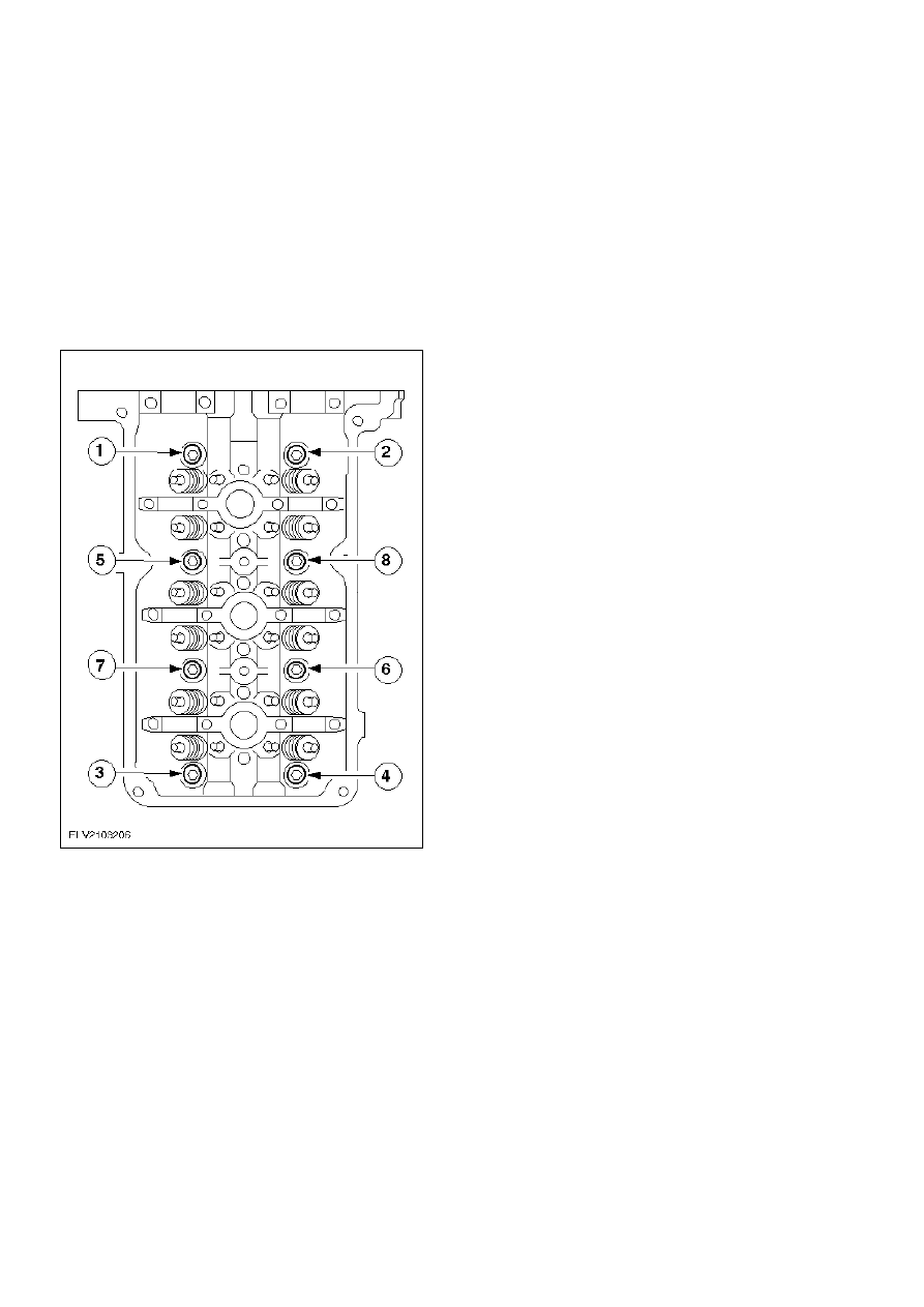
Tighten the bearing caps on the left-hand camshaft.
z
Use thrust bearing caps 1L und 5L to adjust the camshaft end play.
42.
Install the crankshaft pulley/vibration damper bolt.
µ
43.
Position the crankshaft for installation of the right-hand timing chain.
z
Turn the crankshaft clockwise until the Woodruff key is in the 3 o'clock position.
µ
44.
Install the cam followers on the right-hand cylinder head.
z
Use camshaft bearing lubricant.
µ
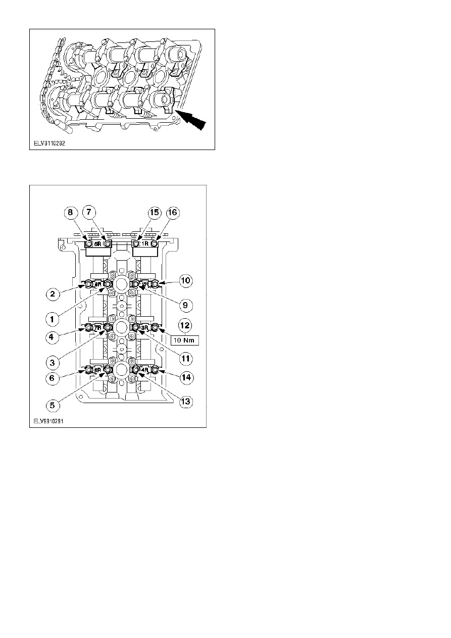
45.
Note:
Tightening sequence.
Tighten the bearing caps on the right-hand camshaft.
µ
46.
Note:
Install the timing case cover within six minutes after applying the sealer.
Install the CKP sensor pulse ring and apply 6 mm of sealer to the indicated areas.
1
Install the CKP sensor pulse ring in the key groove with the blue paint mark.
2
Apply cylinder block sealer.
z
Indentation towards the front.
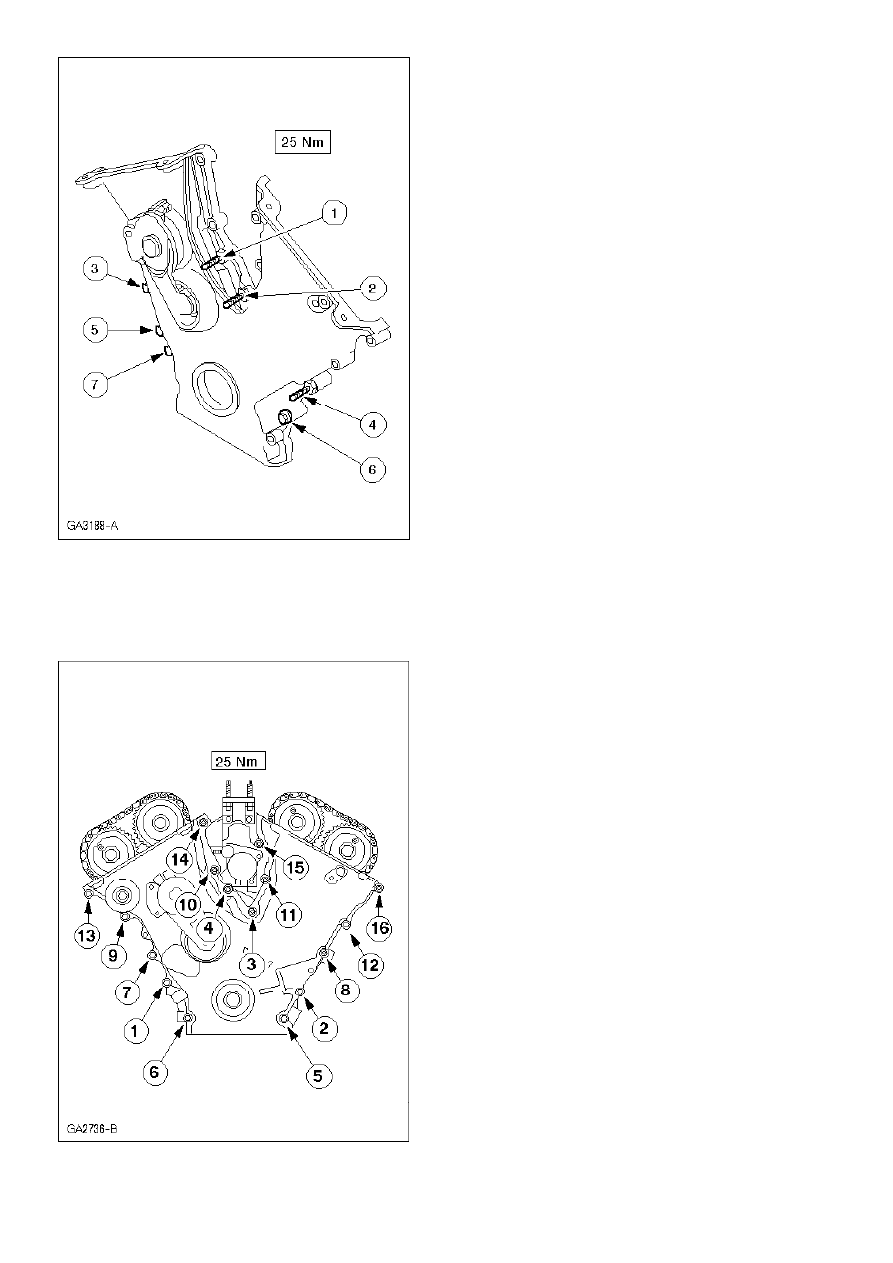
µ
47.
Note:
Install a new timing chain cover gasket.
Install the timing chain cover.
z
Tighten the studs in the sequence shown.
µ
48.
Note:
Tightening sequence.
Tighten the remaining timing chain cover bolts and studs.
µ
49.
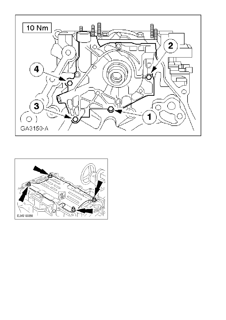
Note:
Coat the new O-rings with engine oil.
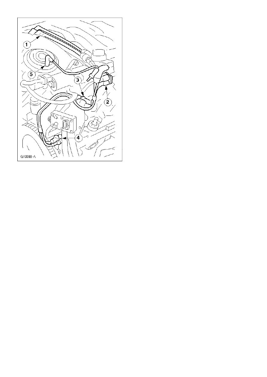
Install the sensors and wiring brackets.
1
CKP sensor
2
CMP sensor.
3
Wiring bracket
4
Wiring bracket
µ
50.
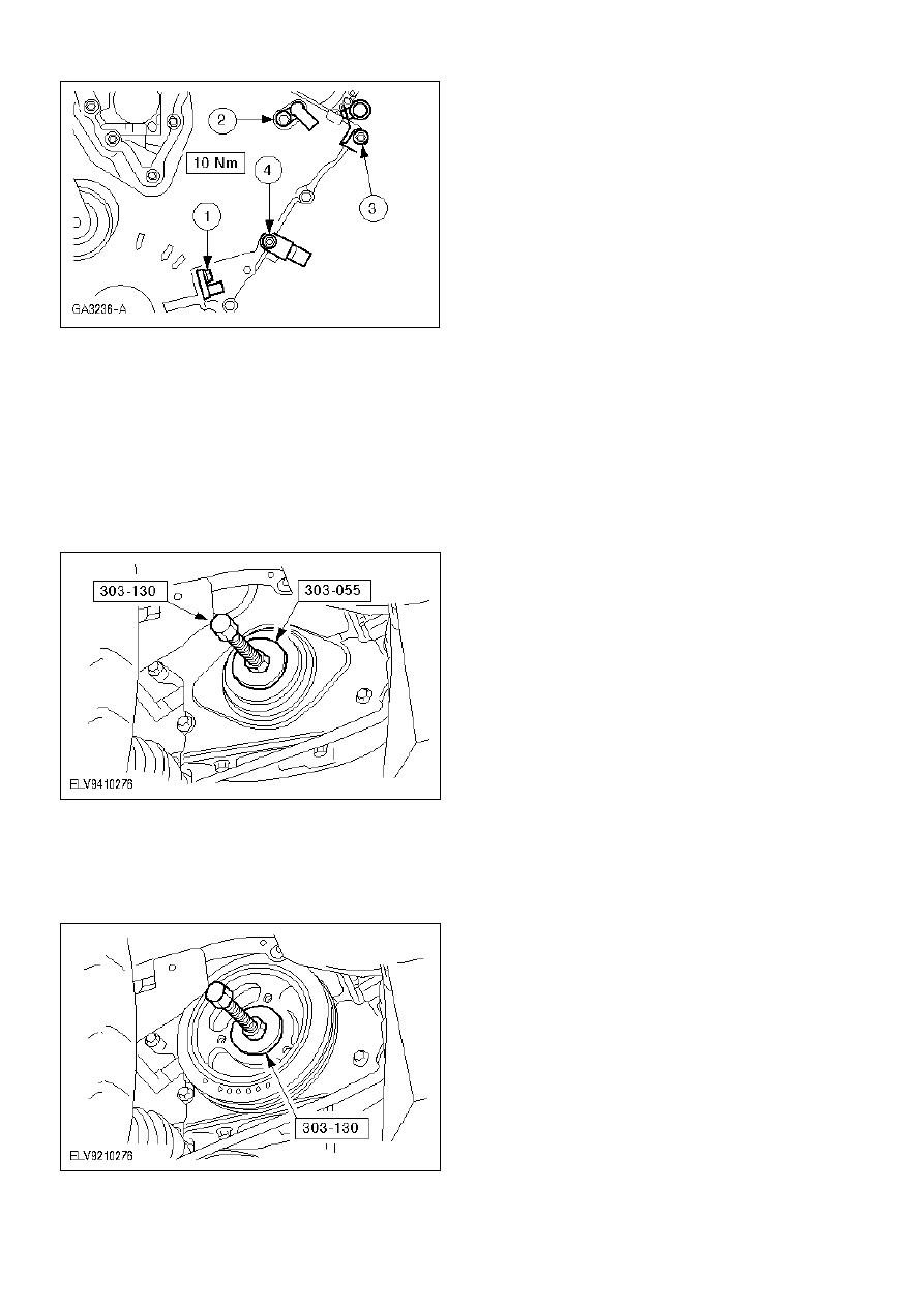
Using the special tool, install the crankshaft front oil seal.
z
Lubricate the outer ring and the sealing lip of the oil seal with engine oil.
z
Draw in the crankshaft front oil seal using the special tool and the washer of the
crankshaft pulley/vibration damper bolt.
µ
51.
Using the special tool, install the crankshaft pulley/vibration damper.
µ
52.
Note:
Tightening sequence.
Using the special tool, install the crankshaft pulley/vibration damper.
z
Seal off the Woodruff key in the crankshaft pulley/vibration damper with silicone sealer
and cylinder block sealer.
z
Tighten the bolt in four stages.
z
Stage 1: 120 Nm
z
Stage 2: Turn the bolt back a full turn.
z
Stage 3: 50 Nm
z
Stage 4: 90 degrees
µ
53.
Note:
Do not tighten the power steering pump bracket retaining bolts and studs at this stage.
Install the power steering pump and bracket.
µ
54.
Note:
The longer 84 mm retaining bolts should be tightened first.
Tighten the 84 mm power steering pump retaining bolts.
µ
55.
Tighten the power steering pump retaining nuts.
µ
56.
Note:
The indentation on the pulley must face towards the front of the engine.
Attach the pulley to the power steering pump.
µ
57.
Install the camshaft oil seal carrier.
z
Insert a new gasket and align the carrier on the locating dowels.
µ
58.
CAUTION:
Do not damage the running surface of the camshaft.
Using the special tools, install the camshaft oil seal.
z
Lubricate the outside of the oil seal with engine oil.
µ
59.
Using the special tool, install the camshaft pulley.
z
Heat the belt pulley, locate it in position and draw it on as far as it will go.
µ
60.
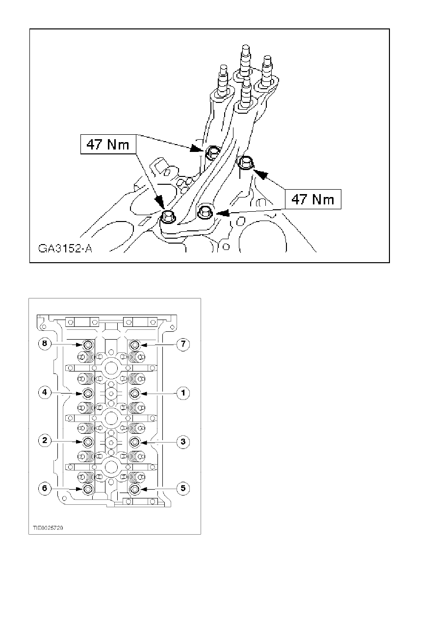
Apply sealer to the cylinder head mating face intersections.
z
Use a silicone gasket and cylinder block sealer.
61.
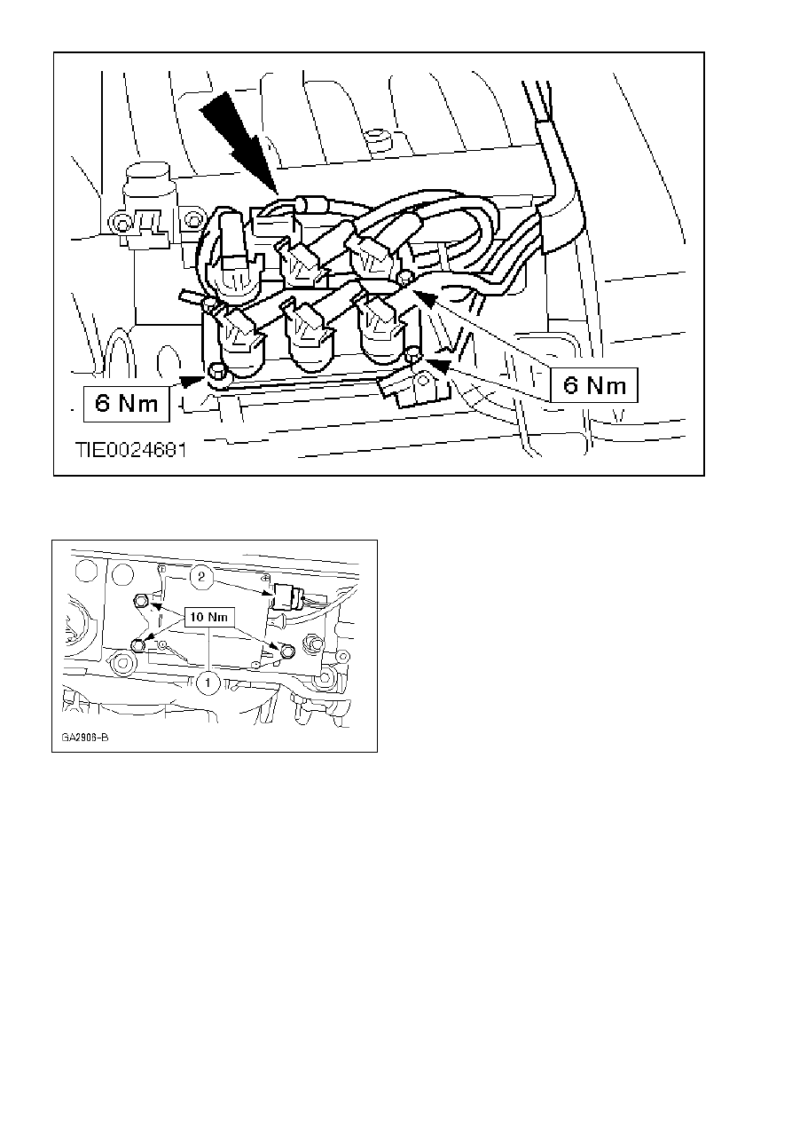
Install the spark plugs - tightening torque 15 Nm.
z
Use spark plug lubricant.
µ
62.
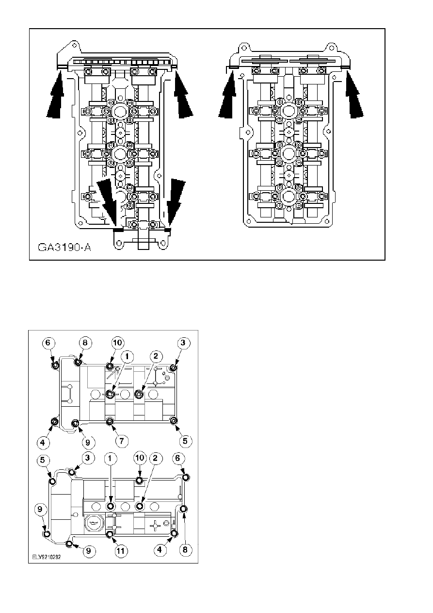
Note:
Install new valve cover gaskets.
Note:
Tightening sequence
Install the valve covers.
µ
63.
Install the wiring harness retaining plate and the left-hand engine lifting eye.
µ
64.
Apply sealer to the mating face intersections.
z
Use a silicone gasket and cylinder block sealer.
z
Apply a 10 mm wide strip of sealer to the points shown.
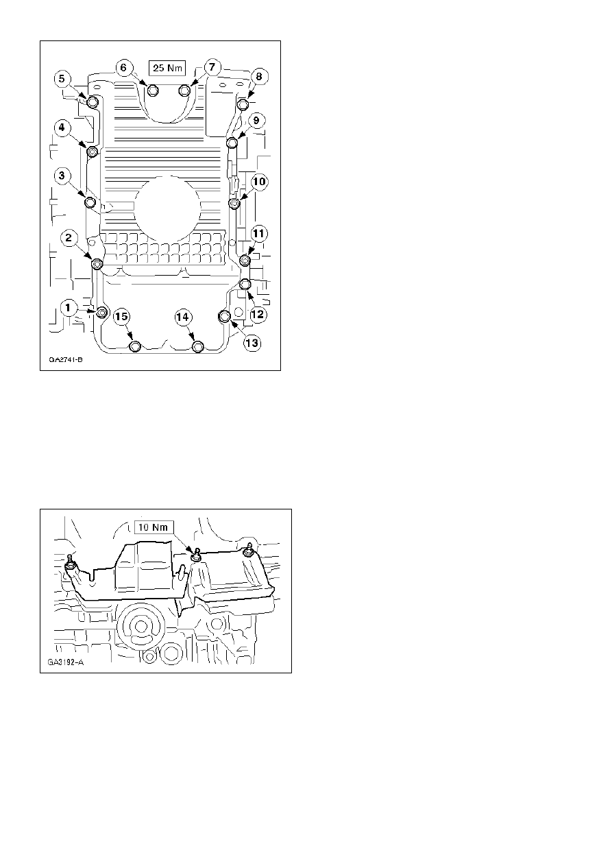
µ
65.
Note:
Location of the studs.
Note:
Tightening sequence
Note:
Install the oil pan within six minutes of applying the sealer.
Install the oil pan with a new gasket.
µ
66.
Install the oil pan heat shields.
µ
67.
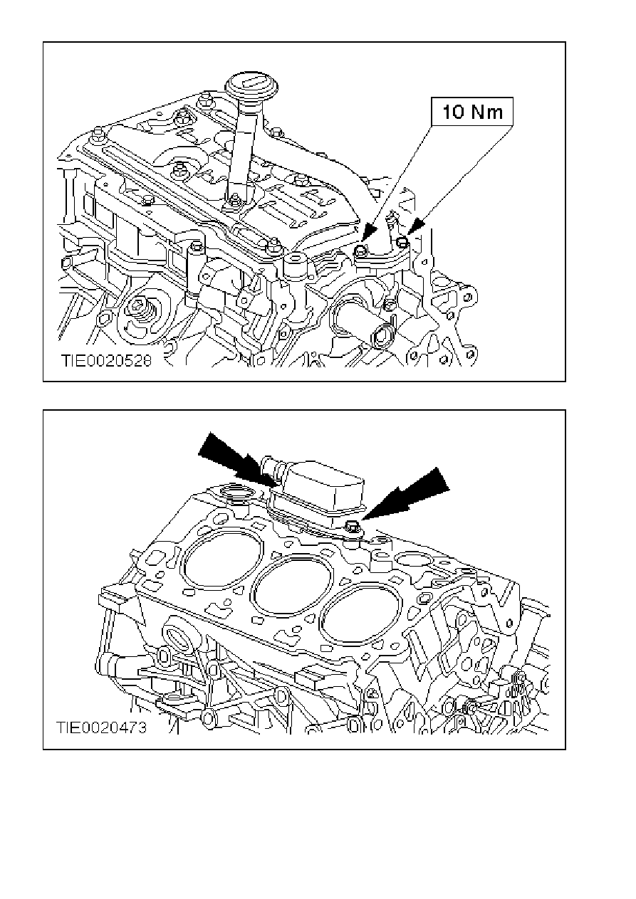
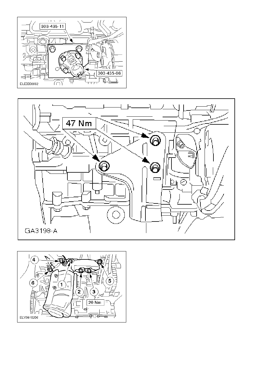
Install the oil cooler and the oil pressure switch.
1
Install the oil cooler retaining bolt.
2
Apply sealer to the thread of the oil pressure switch and install the switch.
z
Coat the oil cooler seal, the O-ring and the oil filter seal with engine oil.
z
Use oil/coolant passage sealer.
µ
68.
Note:
Tightening sequence.
Install the left-hand exhaust manifold and catalytic converter with a new gasket.
µ
69.
Install the oil filter.
µ
70.
Install the generator bracket.
µ
71.
Install the generator.
1
Generator bolts
2
Bracket bolt
µ
72.
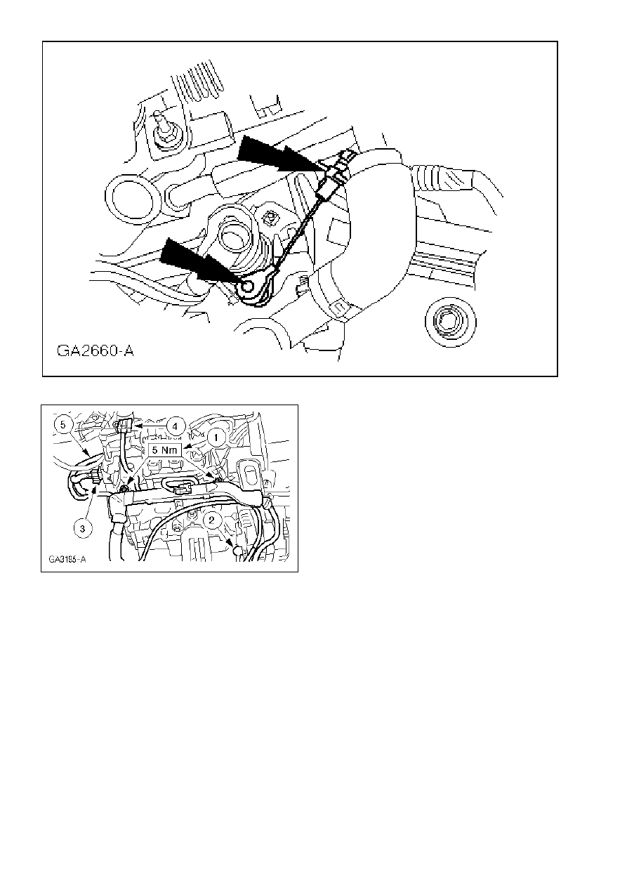
Using the special tools, install the crankshaft rear oil seal.
z
Lubricate the outer ring and sealing lip with engine oil.
µ
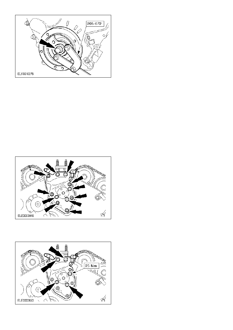
73.
Install the flywheel.
1
Install the adapter plate.
2
Apply sealer to the bolts and tighten them working diagonally.
z
Use flywheel sealer.
z
Using the special tool 205-072, hold the crankshaft by the vibration damper.
µ
74.
Note:
Tightening sequence
Install the coolant pump.
1
Tighten the new bolts in two stages.
z
Stage 1: 10 Nm
z
Stage 2: 90 degrees
2
Connect the coolant hose.
3
Connect the coolant hose.
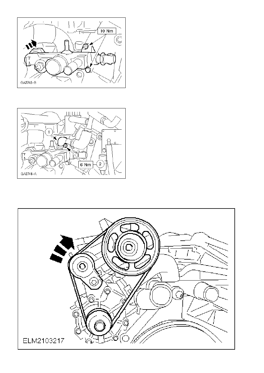
µ
75.
Install the coolant connecting pipe between the cylinder heads.
z
Use new O-rings and coat them with O-ring lubricant.
µ
76.
Attach the positive crankcase ventilation hose and valve.
1
Attach the positive crankcase ventilation hose and valve.
2
Tighten the nut.
µ
77.
Install the water pump drive belt.
z
Rotate the belt tensioner clockwise to release the tension on the belt.
µ
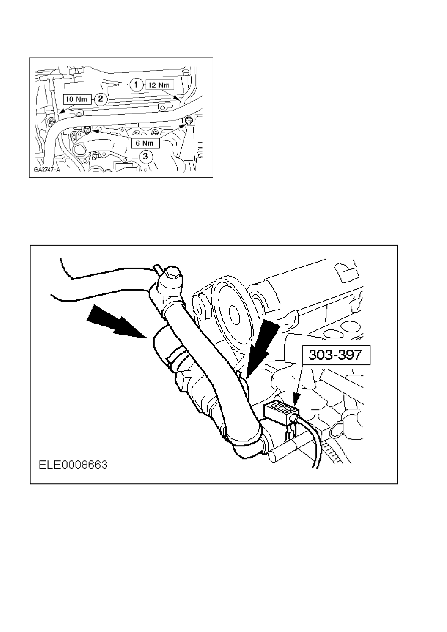
78.
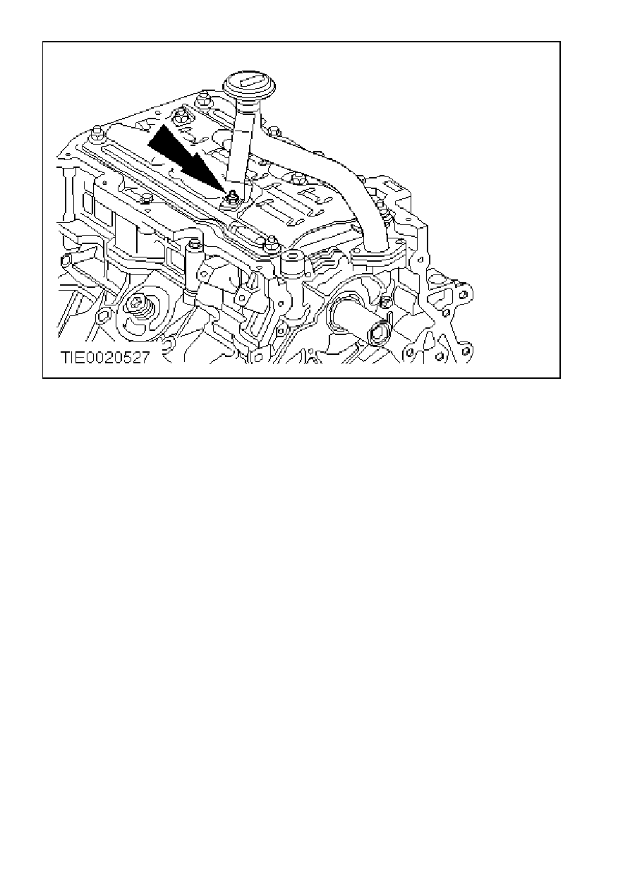
Attach the coolant distribution pipe, the engine lifting eye and the oil dipstick.
1
Install the engine lifting eye.
2
Install the dipstick with a new oiled O-ring.
3
Screw on the nuts.
µ
79.
Using the special tool, install the thermostat housing with the coolant hoses.
µ
80.
Note:
Install new gaskets with the locating lugs facing downwards.
Note:
Tightening sequence
Install the lower the intake manifold.
µ
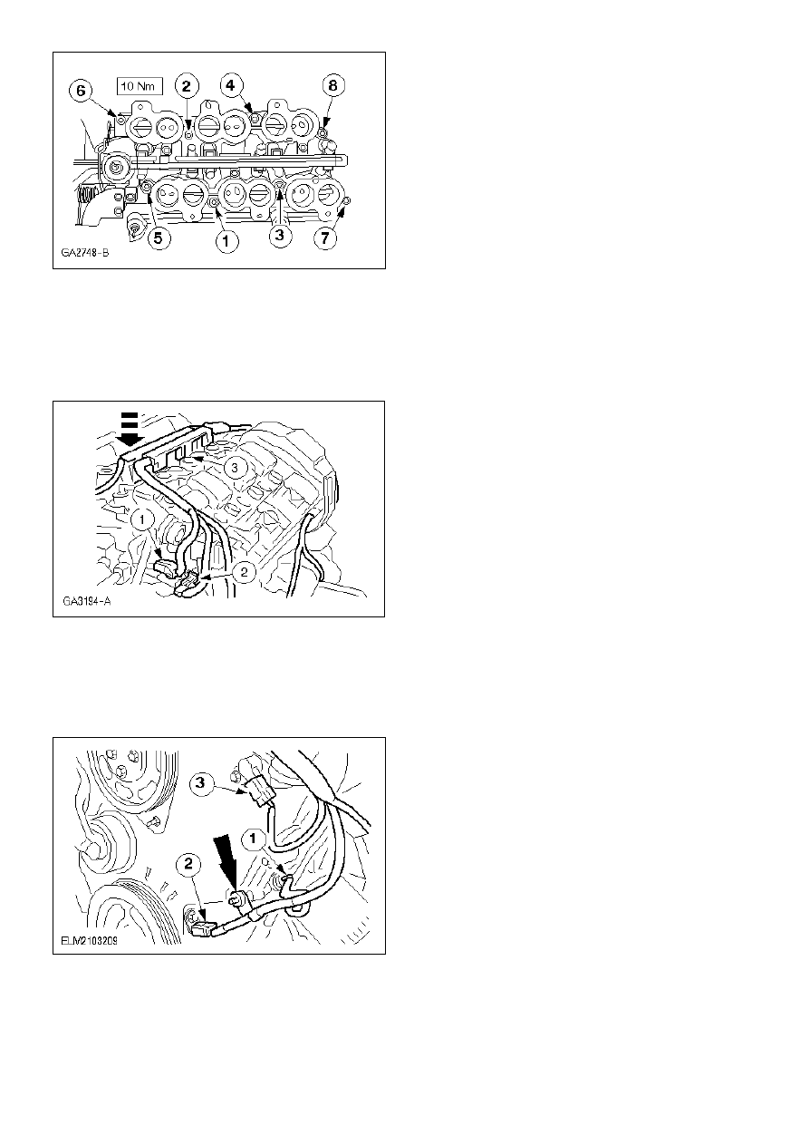
81.
Install the fuel injection system wiring harness.
1
ECT sensor plug
2
DPFE sensor plug
3
Fuel injector connector
µ
82.
Connect the plugs.
1
Oil pressure switch
2
CKP sensor
3
CMP sensor
z
Clip the wiring harness in place.
83.
Connect the HO2S sensor.
µ
84.
Note:
Install new gaskets with the locating lugs pointing downwards.
Note:
Tightening sequence.
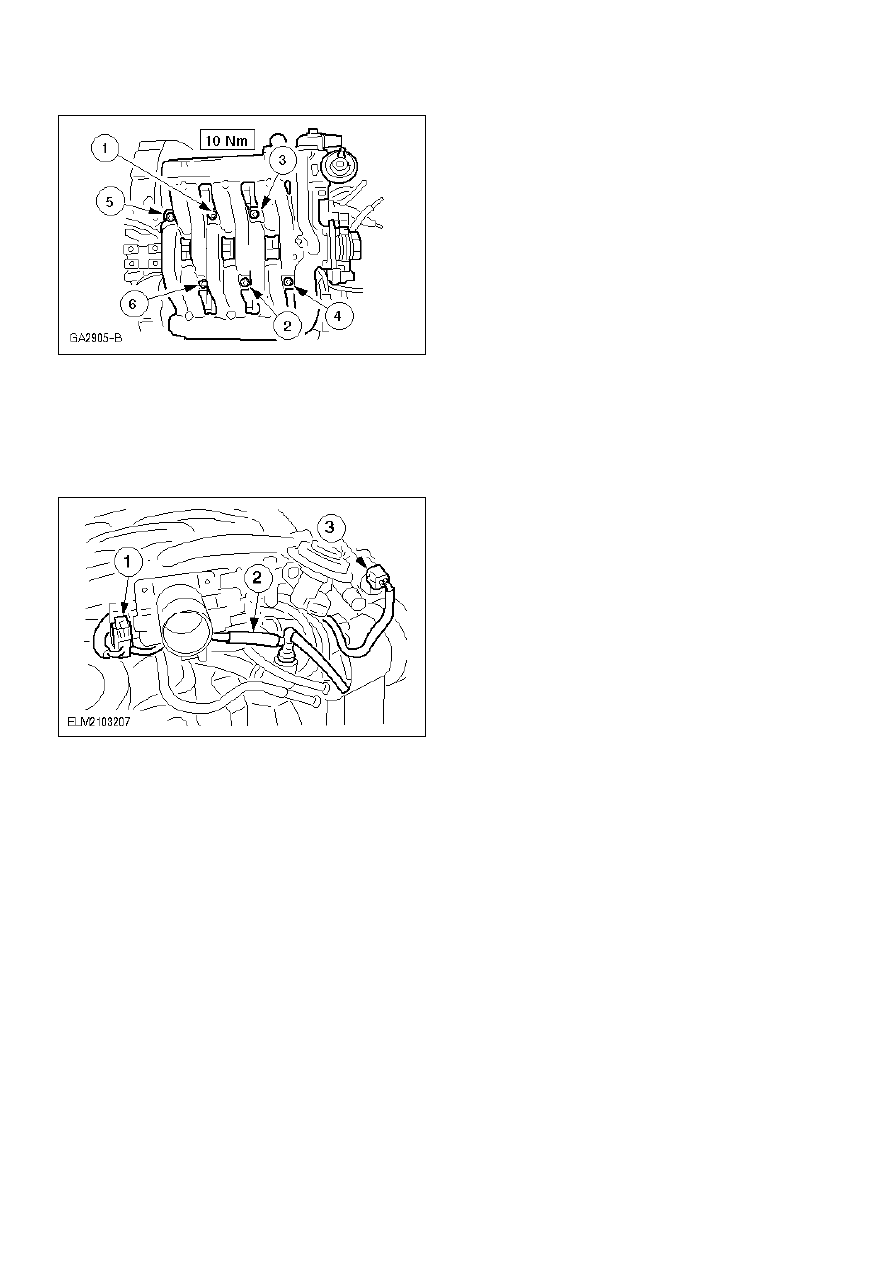
Install the upper part of the intake manifold.
µ
85.
Connect the hoses and plugs
1
Plug to the TP sensor
2
Positive crankcase ventilation hose
3
Plug to the IAC valve
µ
86.
Connect the vacuum hoses.
1
To the upper part of the intake manifold.
2
To the electronic vacuum regulator
3
To the fuel pressure regulator
4
To the DPFE
5
To the EGR valve
µ
87.
Install the electronic ignition (EI) coil.
z
Connect the electrical connectors.
µ
88.
Install the IMRC actuator.
1
Install the retaining bolts.
2
Connect the IMRC electrical connector.
µ
89.
Install the IMRC cable.
µ
90.
Install the wiring harness and connect the electrical conectors.
1
Attach the wiring rail.
2
Generator cable
3
DPFE sensor plug
4
Electronic vacuum regulator plug
5
ECT sensor to coolant connection pipe
µ
91.
Remove the special tools.
µ
92.
Install the intermediate shaft retaining bracket.
µ
93.
Note:
Tightening sequence.
Install the right-hand exhaust manifold with a new gasket.
µ
94.
Connect the EGR pipe to the EGR valve.
1
Screw on the EGR pipe.
2
Connect the hoses to the EGR pipe.
95.
Finishing operations.
z
Fill the engine with engine oil.
Wyszukiwarka
Podobne podstrony:
Piernikowa chatka ze schematem złożenia
06 pamięć proceduralna schematy, skrypty, ramyid 6150 ppt
7 aglebra schematow bloczkowych
wZ 2 Budowa wiedzy społecznej teoria schematów
3 ogolny schemat replikacji i onkogeza DNA wirusowa
Schematy animacji
wykład 5 schematy, przywileje, role
schemat mechanika
schemacik prezentacji
5 Algorytmy i schematy blokowe
D Studiowe PKM Wał Wał złożeniowy Model POPRAWIONY
Propozycja przygotowania schema Nieznany
f Obraz 6 plan 1 schemat
Podnośnik śrubowy rysunek złożeniowy
GH 7 082 schemat
poznawczo behawioralne schematy poznawcze
więcej podobnych podstron