
MJoy16-C1
Multifunction Home Simulator Cockpit Controller
User’s Manual
version 1.1
written by Mindaugas Milasauskas
reviewed by Jan L. F. Bos
Copyright (C) 2005 Mindaugas Milasauskas, mindaug@mindaugas.com

MJoy16-C1 User’s Manual
www.mindaugas.com
Contents
Contents .......................................................................................................................... 2
Disclaimer........................................................................................................................ 3
Introduction...................................................................................................................... 4
Controls ........................................................................................................................... 5
Analogue axes inputs .................................................................................................. 5
Button Controls ............................................................................................................ 5
Pushbuttons................................................................................................................. 5
Toggle switches ........................................................................................................... 6
Rotary switches ........................................................................................................... 6
“Init” button................................................................................................................... 7
Controls Mapping “Mode” switch ................................................................................. 7
“Centre” switch for auto centring feature disabling....................................................... 7
Controls naming convention ........................................................................................ 8
Controls matrix layout .................................................................................................. 8
Boards description........................................................................................................... 9
MJoy16 board description............................................................................................ 9
Key Matrix board description ..................................................................................... 11
Installation ..................................................................................................................... 13
Installing MJoy16 and Key Matrix boards .................................................................. 13
Power supply ............................................................................................................. 14
Wiring MJoy16-C1......................................................................................................... 15
Overall wiring layout .................................................................................................. 15
Wiring potentiometers and other analogue sensors................................................... 17
Wiring digital controls................................................................................................. 19
About use of diodes and their polarity .................................................................... 19
Wiring digital controls without Key Matrix board..................................................... 20
Wiring digital controls with Key Matrix board.......................................................... 21
Wiring pushbuttons ................................................................................................ 22
Wiring toggle switches............................................................................................ 23
Wiring rotary switches ............................................................................................ 24
Wiring Hat switch ................................................................................................... 25
Wiring “Init” button .................................................................................................. 27
Wiring “Mode” and “Centre” switches ..................................................................... 27
Controls Mapping .......................................................................................................... 28
Setting up MJoy16-C1 in Windows................................................................................ 30
About limitation of 32 buttons per joystick.................................................................. 30
Translating joystick buttons to keyboard keys............................................................ 30
Multiple joysticks in Windows..................................................................................... 31
Credits ........................................................................................................................... 32
Legal ............................................................................................................................. 32
Appendixes.................................................................................................................... 33
A1. MJoy16-C1 wiring schematic diagram without Key Matrix board ........................ 33
A2. MJoy16-C1 wiring diagram with Key Matrix board .............................................. 35
2

MJoy16-C1 User’s Manual
www.mindaugas.com
Disclaimer
This documentation is provided for the purpose to be useful aid for implementing
MJoy16-C1 for your own application. It is meant to be used while complying with all
safety and sensitive electronics handling measures. We CAN NOT BE HELD
RESPONSIBLE for any damage or injury of any kind which may occur or could occur
either during building, testing, use or storage. Use this material AT YOUR OWN RISK
AND JUDGEMENT.
Printed copies of this document are uncontrolled.
Latest official version is located on
http://www.mindaugas.com
website.
3

MJoy16-C1 User’s Manual
www.mindaugas.com
Introduction
At first what the name MJoy16-C1 means. The name MJoy16-C1 consists of two parts.
MJoy16 is a new USB controller design which has evolved from the original MJoy. “16”
means that it uses a more powerful chip which is, of course, better than 8.
As MJoy16 is capable of performing a lot of different tasks “C1” has been added to
indicate that this MJoy16 is a multifunction home sim-cockpit controller.
MJoy16-C1 is a cost-effective hardware solution for those who want to build aircraft or
other cockpit simulator. Under Windows it will be conveniently recognized as a Plug-
and-Play joystick. But it is much more! It has significant enhancements which make it
much better suited for cockpit applications than an ordinary joystick.
It has 8 high resolution analogue axes inputs. These inputs may be connected to
various analogue input controls like joystick or yoke axes, rudder pedals, throttle(s),
flaps, trimmers etc.
In addition to precision axes MJoy16-C1 supports many buttons and switches. It
supports as much as 64 simple pushbuttons, 16 toggle switches, 4 rotary switches and
1 hat switch.
If you choose a simple cockpit solution you might just need to prepare a front panel with
holes and artwork, place buttons, pots and switches and connect them to controller.
This connection is done by simply soldering wires of MJoy16-C1’s flat ribbon cables
straight to the controls. Connecting joystick, pedals, throttle and other axes might
involve more work. You may as well choose to use this MJoy16-C1 controller in tandem
with your favourite joystick. In this way you’ll have even less work on analogue axes as
you may put MJoy16-C1’s analogue controls as potentiometers on the panel which may
be used for trimmers, mixture, flaps etc.
Of course, as always, more reality in your cockpit means more work for yourself.
USB interfacing makes this controller a true Plug-and-Play device. You just need to plug
it into your PC’s USB port and let Windows discover it. It’s just that simple!
As a next step you will have to map your new joystick controls to your favourite flight
simulator.
4
Below is the features and characteristics list of MJoy16-C1:
Interface to host computer
USB 1.1
USB interface speed
Low
Analogue axes and rotary switches update period
30ms
Buttons and toggle switches update period
60ms
Number of analogue inputs
8
Analogue inputs resolution
10 bits
Number of pushbuttons
64
Number of toggle switches
16
Toggle switch action
Double
Number of rotary switches
4
Rotary switch action
Double-speed
Number of 8-way hat switches
1
Automatic calibration feature
Included
Centring feature with disabling possibility
Included
Controls mapping mode selection feature
Included

MJoy16-C1 User’s Manual
www.mindaugas.com
Controls
This chapter describes the types of controls supported by MJoy16-C1. It will also
explain how they operate and how to use them.
Analogue axes inputs
The controller’s analogue axes appear in Windows game control panel as X, Y, Z, Rx,
Ry, Rz, Dial and Slider. They all have 10 bits resolution.
Input signal is simply a voltage between roughly 0 and 5 Volts. It is usually taken from
potentiometers that are connected to various rotating and sliding controls.
Details how to connect them are given in the wiring section.
MJoy16-C1 has an auto calibration feature so you don’t have to worry about calibration
in Windows. To calibrate all controls simply move the control back and forth to its travel
edges.
If you need to recalibrate controls press and hold the “Init” button while plugging the
controller into USB. In this case all axes controls will loose their calibration and will need
to be recalibrated.
Axes X, Y and Rx have a centring feature. These axes are usually used for joystick /
yoke and rudder controls which are usually spring-loaded and return to centre position
when released. This centre position is read during controller start-up and used during
operation. Therefore it is important to leave these axes (joystick/yoke and pedals) in
centre position when powering on your PC or plugging in MJoy16 to USB. This centring
feature may be disabled by “Centre” switch.
Button Controls
The controls described in following sections are common as they all are digital controls
and use joystick button states to transfer their data to PC. Please note that here by
joystick button we mean not buttons wired on the panel but rather joystick button states
which are transmitted to PC via the USB cable. We will call the physical buttons
“pushbuttons” to indicate a clear difference. How controls are connected and what
button presses are generated during their operation is described in the Controls
Mapping section.
Pushbuttons
These are most basic controls found on every joystick. Their operation is exactly the
same as on any ordinary joystick. The only difference is that there are lots of them.
Ordinary joysticks usually have from 4 to 12 pushbuttons. This controller has support for
64 pushbuttons giving much more possibilities.
Pushbutton contacts are of the “normal open” type. When engaged their contacts are
“closed”.
5

MJoy16-C1 User’s Manual
www.mindaugas.com
Toggle switches
Toggle switch support is an enhanced MJoy16-C1 feature. It translates changes of
toggle switch position into momentary joystick button presses. There might be two ways
of performing this translation. One way is generating the same button press when toggle
switch is switched “ON” or “OFF”. The other way is generating different button presses
when switch is toggled “ON” and “OFF”. And guess what - this way is used in MJoy16-
C1 controller. That’s why their type is called “double-action”.
Toggle switches are arranged in rows by 8. As each toggle switch generates different
button presses for “ON” and “OFF” flip. 8 toggle switch rows generate up to 16 different
button presses. These button positions are arranged in such a way that lower 8-position
row buttons are momentary activated when toggles switches are flipped to “ON”
position. Whereas the upper row is activated when they are flipped “OFF”.
To illustrate: Suppose we flip toggle switch 1 to “ON” position. It generates a brief
Button 17 press. Then we flip it back to “OFF”. It generates Button 25 press. It’s like
Gear Up / Down.
MJoy16-C1 has support for up to 16 toggle switches. Exact mapping which toggle
switches generate which button presses is described in Controls Mapping chapter.
Please read about “Init” button to learn more about toggle switches.
Rotary switches
Support for rotary switches is implemented in flight simulators to facilitate control of
radios, autopilot settings etc. All these controls are operated by rotary knobs. One
example of such simulator is Microsoft Flight Simulator tm.
MJoy16-C1 supports “phase-shifted” rotary switches. They have three leads and look
very similar to ordinary pots. How to connect these switches is described in wiring
installation chapter.
In similar fashion as with toggle switches, the controller translates raw signals from
these rotary switches to corresponding momentary button presses. One brief button
press is generated when this rotary switch is rotated in clockwise (CW) direction and
other when in counter-clockwise (CCW). Depending on the exact type of rotary switch
full rotation of it might generate from around 10 to 20 pulses.
For example: If we map CW and CCW button presses Button1 and Button2 to increase
or decrease Com1 radio frequency fractional part then we’ll be able to exactly adjust
frequency setting fractional part by rotating rotary switch knob in one or the other
direction.
This would be very nice but inconvenient if you need to change from one frequency to
another which is far apart. To solve this real radios have two co-axial knobs one inside
another, which change either whole or part of the frequency.
In MJoy16-C1 this is solved in a different way. In this controller rotaries’ processing is
made dependent on how fast you rotate the rotary switch. It sends one button press if
you rotate knob slowly and other if you twist it fast. So in this case fast knob rotation
would generate button presses Button9 and Button10. As you can see one rotary switch
utilizes 4 buttons. If you map Fractional_Increment to Button1, Whole_Increment to
Button9 and decrements to buttons 2 and 10 respectively you will get fully functional
rotary switch operation to control Com radio frequencies etc.
6

MJoy16-C1 User’s Manual
www.mindaugas.com
In this way it provides natural and comfortable use and it does not require any time to
get used to. You instinctively rotate the knob faster when you want to change the
number by larger amount.
“Init” button
MJoy16-C1 has another convenient feature which is related to toggle switches and axis
calibration. If the “Init” button is pressed during the powering of MJoy16 the calibration
data is reset to defaults and all axes will be recalibrated as from a fresh start. By
powering on we mean powering on the PC while having the MJoy16 connected or re-
plugging the MJoy16 into USB port of your computer
During normal operation this “Init” button may be used to transmit all double-action
toggle switches states by generating short key presses of according switches that are
transmitted to computer. It might be useful when you start a new game or flight and
want your simulator to be in sync with toggle switches states of your panel.
If you use this button it is recommended to place it at a convenient place on the panel
where it would not interfere with main simulator controls but would be easily accessible
for start-up initialization of the flight.
Controls Mapping “Mode” switch
This mapping mode switch allows you to choose between two layouts of buttons. It
initializes the mode when MJoy16 is powered on. The “Off” position means Mapping
Mode 1 and “On” – Mapping Mode 2. About the exact mapping of controls please read
the Controls Mapping chapter.
Please note that if you change Mode switch selection you will need to restart the
MJoy16 controller. For this you should disconnect the MJoy16 and reconnect it back to
the host USB port.
“Centre” switch for auto centring feature disabling
This switch controls whether to use auto centring feature or not. If this switch is left open
or in the “Off” position then auto centring is enabled and axes X, Y and Rx register their
centre position when MJoy16 is powered up. This is useful when MJoy16-C1 is used as
main controller in the sim cockpit which has connected joystick, rudder pedals, throttle
etc.
When this switch is “On” and contacts are closed auto centring feature is disabled. In
this case centre is not being read from axes X, Y and Rx during start-up. This mode
might be useful if MJoy16-C1 is used for other controls like throttle quadrant, flaps,
trimmers etc.
The same as “Mode” this switch takes effect only during start-up of the controller. If you
change its selection you will have to restart the controller.
7
MJoy16-C1 User’s Manual
www.mindaugas.com
Controls naming convention
By convention we will reference all wires of matrix which are outputs of microcontroller
as columns and inputs as rows. Matrix is of 12 rows x 8 columns format.
By convention buttons are named by a Latin letter identifying a row and a digit which
identifies a column. So rows are named A, B, C, D, E, F, G, H, I, J, K, L. Columns are
numbered from 1 to 8. Examples of names are A2, C3, and F5 etc.
This is simple with pushbuttons which use one contacts pair. But more complex controls
like rotary switches would require more pairs. In this way phase shifted rotary switch will
use two buttons. For example one rotary will utilize buttons contact pairs D1 and D2. It
will be named as D1-2 or D12.
This naming convention will be used to refer to specific controls in text, diagrams and
tables throughout this document.
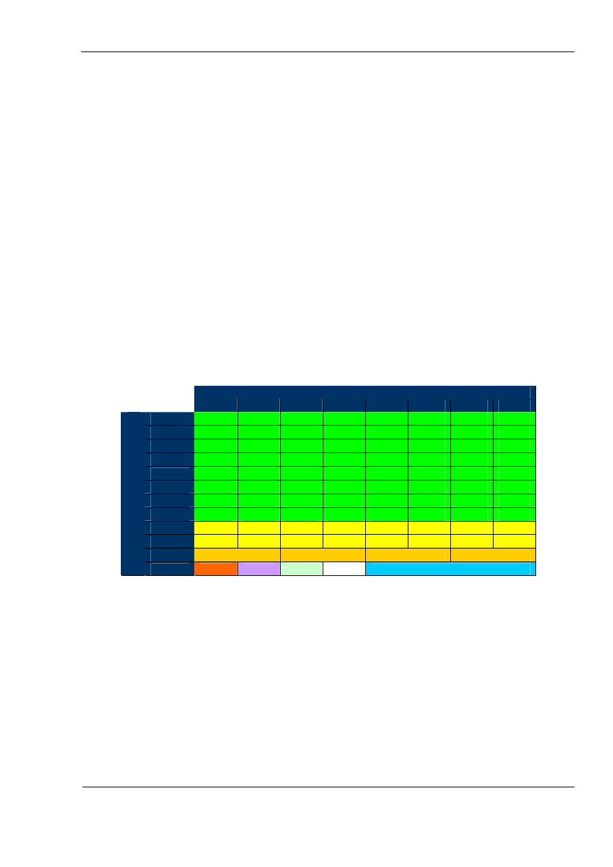
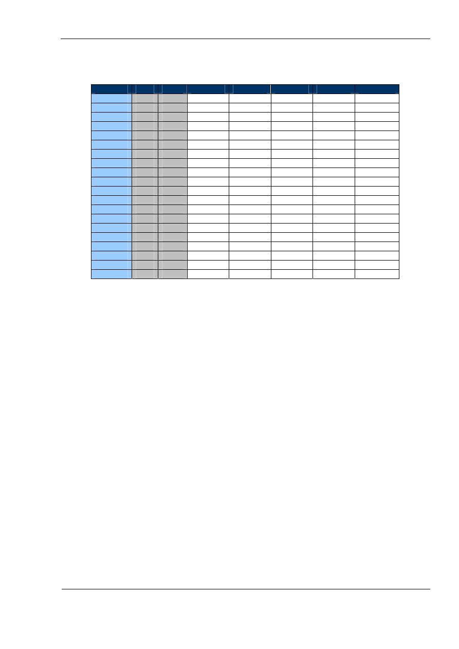
Controls matrix layout
Controls are laid out in a matrix fashion in MJoy16-C1 controller. Names for controls are
used as described in naming convention above. Below is the table which shows what
controls use what positions in the matrix:
Column
1
2
3
4
5
6
7
8
A
Button
Button
Button
Button
Button
Button
Button
Button
B
Button
Button
Button
Button
Button
Button
Button
Button
C
Button
Button
Button
Button
Button
Button
Button
Button
D
Button
Button
Button
Button
Button
Button
Button
Button
E
Button
Button
Button
Button
Button
Button
Button
Button
F
Button
Button
Button
Button
Button
Button
Button
Button
G
Button
Button
Button
Button
Button
Button
Button
Button
H
Button
Button
Button
Button
Button
Button
Button
Button
I
Toggle Toggle
Toggle
Toggle
Toggle
Toggle Toggle Toggle
J
Toggle Toggle
Toggle
Toggle
Toggle
Toggle Toggle Toggle
K
Rotary
Rotary
Rotary
Rotary
Row
L
Init
Mode
Centre
Hat switch
As we see from the table above we have 64 pushbuttons named from A1 to H8, 16
toggle switches named from I1 to J8, 4 rotary switches named from K12 to K78, “Init”
button L1, “Mode” switch L2, “Centre” switch L3 and hat switch L5678.
8
MJoy16-C1 User’s Manual
www.mindaugas.com
Boards description
MJoy16-C1 consists of two boards:
• MJoy16
• Key Matrix board.
Key Matrix board is not necessary but helps to reduce the wiring complexity.
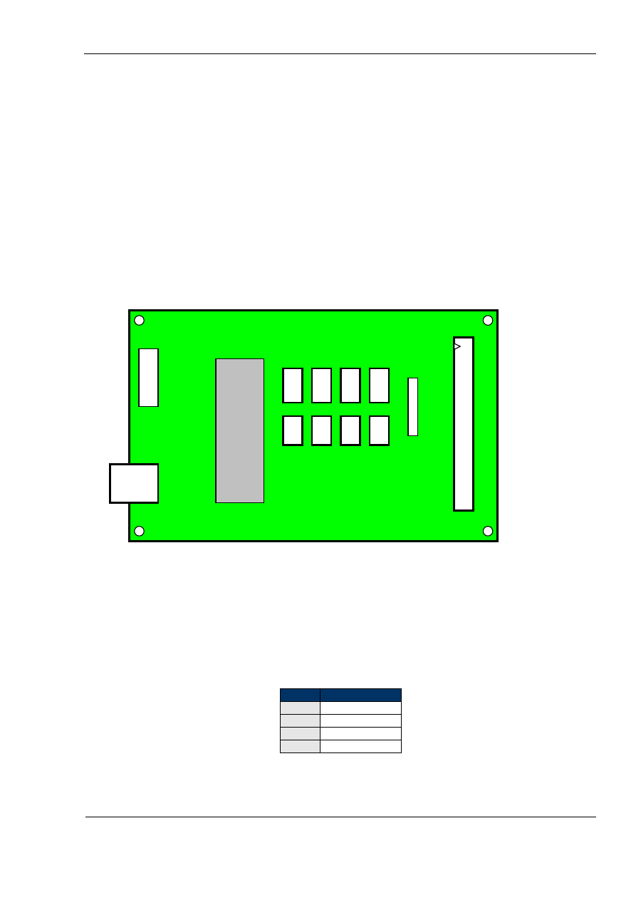
MJoy16 board description
MJoy16 board layout is illustrated below:
MJoy16 board
G
H
E
F
Analog inputs
C
ISP socket
D
A
B
1
Rx
Z
Y
X
GND
GND
2
-
-
Pactch pins
3
-
Digital inputs
-
4
-
-
-
-
ATmega16
-
-
Slider
chip
Rz
Ry
Dial
-
-
-
-
+5V
+5V
7
8
5
6
3
4
USB
socket
1
2
K
L
I
J
-
-
The main connectors on MJoy16 board are USB socket, Analogue Inputs and Digital
inputs. The board USB socket takes a B type USB cable which connects it to host
computer.
Analogue inputs are eight 4-pin sockets for connecting potentiometers or other
analogue sensors for axis inputs. Corresponding axis of each socket is marked on the
MJoy16 board diagram. Pin names and functions are shown in the table below:
Pins
Signal Name
1
Input Signal
2
GND
3
-
4
+5V
Analogue sensor wiring is explained in detail in wiring chapter.
9
MJoy16-C1 User’s Manual
www.mindaugas.com
Digital input is done via one 40-pin socket which is used to connect all digital controls
such as pushbuttons, toggle switches, hat switches etc. This socket may be used to
connect the controls directly or via Key Matrix board. Direct wiring would require
complex wiring including diodes to be connected directly to the switches on the
backside of the panel. Using Key Matrix board does simplify wiring a great deal.
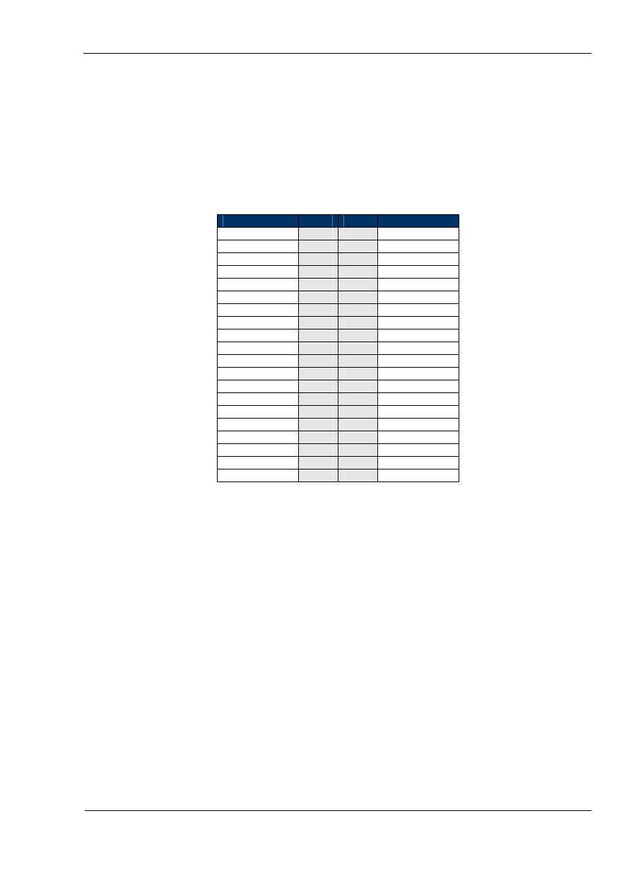
Names of each pin of the Digital Inputs connector of MJoy16 are shown on the board
layout diagram above and in the corresponding table below:
MJoy16 Digital Inputs connector pin-out
Signal Name
Pins
Pins
Signal Name
Row H
1
2
Row G
Row F
3
4
Row E
Row D
5
6
Row C
Row B
7
8
Row A
GND
9
10
GND
-
11
12
-
-
13
14
-
-
15
16
-
-
17
18
-
-
19
20
-
-
21
22
-
-
23
24
-
+5V
25
26
+5V
Column 8
27
28
Column 7
Column 6
29
30
Column 5
Column 4
31
32
Column 3
Column 2
33
34
Column 1
Row L
35
36
Row K
Row J
37
38
Row I
-
39
40
-
For example if you would connect Row A pin to Column 3 pin you will get button A3
press.
Detailed wiring of different digital controls is described in the wiring chapter.
Patch pins are reserved for possible future use. They can be connected to Analogue
inputs by jumper wires to provide additional digital connections on the Digital Inputs
interface. Of course for this application a different code will be needed in the ATmega16
chip which would use these pins not as ADCs but as general purpose digital pins.
The ISP connector is for connecting the MJoy16 to a computer for writing software to
the ATmega16 chip.
10
MJoy16-C1 User’s Manual
www.mindaugas.com
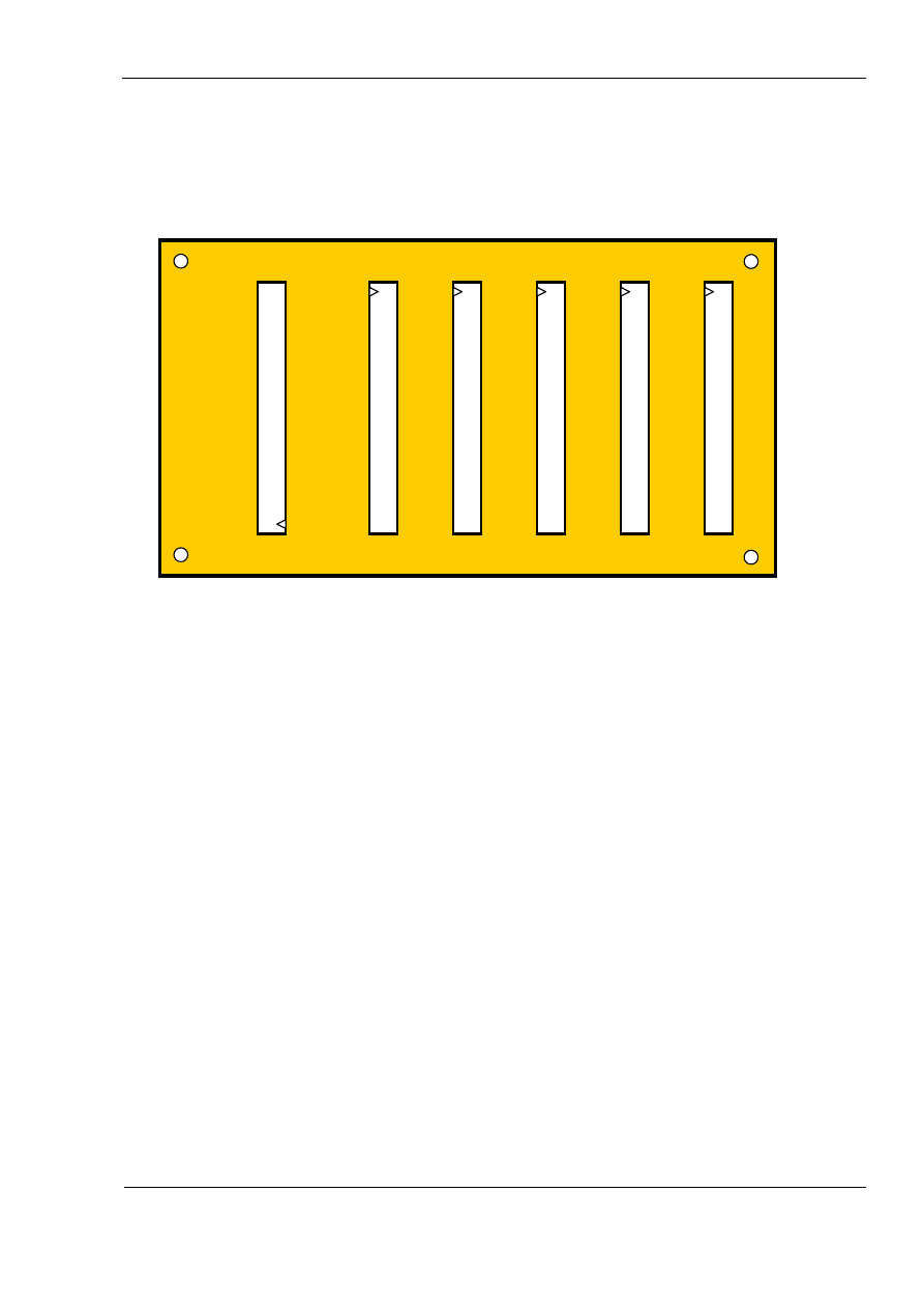
Key Matrix board description
Key Matrix is an optional board which significantly reduces digital controls wiring
complexity. Below is the picture of Key Matrix board layout:
Key Matrix board
11
Key Matrix board consists of digital inputs and outputs.
The Output socket is meant to be connected to MJoy16 via 40 wire flat ribbon cable. It
could be the type of cable that is used for IDE hard disk drives in PCs. But you can also
make this cable easily yourself. For this you’ll have to buy from local electronics shop
required length of plain 40-pin flat ribbon cable and 40-pin snap-on connectors. These
connectors are exactly the same as on IDE cables but are in non-assembled condition
yet. Two connector parts are simply pressed against each other onto the cable till they
clamp on and make a good contact with wires. It is recommended to use some kind of
table press device as it won’t be enough force to do it by hands. Doing this with pliers
could result in uneven pressure or even break of connector. Making this cable yourself
would allow you to choose the length which best suits your installation layout.
General recommendation is to keep this cable as short as possible.
Digital inputs sockets accept 40-pin connectors with flat ribbon cables going directly to
controls. This cable is similar to one described above but with 40-pin connector only on
one end. Each two adjacent pins form a contact pair for one button control in matrix.
Pair names are shown on the above layout diagram according to the naming convention
next to input connector’s positions. For example if you want to connect button C3 you
will use wires 5 and 6 of flat ribbon cable connected to “Inputs 3” socket.
Digital outpu
t to MJo
y16
Digital inputs 2
Digital inputs 3
Digital inputs 4
Digital inputs 5
Digital inputs 1
F1
H1
C1
L1
J1
F2
H2
C2
L2
J2
F3
H3
C3
L3
J3
F4
H4
C4
L4
J4
F5
H5
C5
L5
J5
F6
H6
C6
L6
J6
F7
H7
C7
L7
J7
F8
H8
C8
L8
J8
E1
G1
B1
K1
I1
E2
G2
B2
K2
I2
E3
G3
B3
K3
I3
E4
G4
B4
K4
I4
E5
G5
B5
K5
I5
E6
G6
B6
K6
I6
E7
G7
B7
K7
I7
E8
G8
B8
K8
I8
D1
A1
A5
D5
D2
A2
A6
D6
D3
A3
A7
D7
D4
A4
A8
D8
MJoy16-C1 User’s Manual
www.mindaugas.com
Below is the table which shows Key Matrix board input connectors’ layout structure
in detail:
Position
Pins
Pins
Inputs 1
Inputs 2
Inputs 3
Inputs 4
Inputs 5
1
1
2
L1 J1 C1 F1 H1
2
3
4
L2 J2 C2 F2 H2
3
5
6
L3 J3 C3 F3 H3
4
7
8
L4 J4 C4 F4 H4
5
9
10
L5 J5 C5 F5 H5
6
11
12
L6 J6 C6 F6 H6
7
13
14
L7 J7 C7 F7 H7
8
15
16
L8 J8 C8 F8 H8
9
17
18
K1 I1 B1 E1 G1
10
19
20
K2 I2 B2 E2 G2
11
21
22
K3 I3 B3 E3 G3
12
23
24
K4 I4 B4 E4 G4
13
25
26
K5 I5 B5 E5 G5
14
27
28
K6 I6 B6 E6 G6
15
29
30
K7 I7 B7 E7 G7
16
31
32
K8 I8 B8 E8 G8
17
33
34
A5 D5 A1 D1
18
35
36
A6 D6 A2 D2
19
37
38
A7 D7 A3 D3
20
39
40
A8 D8 A4 D4
For simple pushbuttons there are 2 wires running directly to each button straight from
the connector. For more complex controls like rotary switches and hat switch there are
more wires running to each control. Exact wiring of each type of the controls is
described in the wiring chapter.
12
MJoy16-C1 User’s Manual
www.mindaugas.com
Installation
Installing MJoy16 and Key Matrix boards
ESD Hazard Note:
MJoy16 and Key Matrix board contain sensitive semiconductor
devices and are subject to Electrostatic Discharge (ESD) hazard. So care should be
taken when handling them. It is strongly advised to wear an electrostatic wrist wrap
connected to ground or chassis of the installation site.
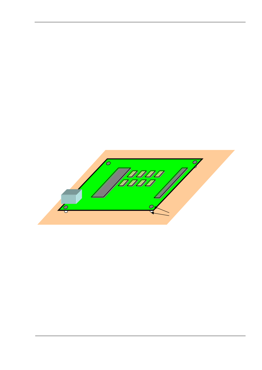
MJoy16 has some sensitive analogue circuits for reading analogue controls therefore it
is advised to install MJoy16 board to a grounded site. Four mounting screws may
provide a ground connection of the MJoy16 board to the panel. It is also advised to
have the back of the board supported by ground-shielded plate. Possible good
installation places may be grounded metal or metal-covered cockpit panel backplane.
This could also be an unetched PCB board etc. All of this is advisory. You will have
good quality operation even without these special shielding measures and you might not
experience any problem. Nevertheless good shielding will contribute to good jitter-free
analogue axis operation.
Below is an example of MJoy16 installation on grounded base:
MJoy16 board
Ground contact
metal grounded base
Generally your cockpit frame should be grounded to minimize possible interference. But
some cockpit designs might have some power actuators installed. In these cases such
power devices ground should be separated from signal ground and filtering measures
installed if needed. MJoy16 board should be connected to signal ground plane.
The Key Matrix board does not carry analogue signals so it does not require explicit
shielding measures. General advice is to install Key Matrix at a location where it will
have the shortest lengths of cables.
Key Matrix is connected to sim cockpit panel controls using 40-wire flat ribbon cables.
These cables have 40-pin connector clamped on one end which connects to the 40 pin
sockets. Other end wires will be split and run directly to the controls of the panel. It is
recommended to keep these wires laid out in bundles along panel sides provide a
convenient and nice layout.
13

MJoy16-C1 User’s Manual
www.mindaugas.com
Power supply
MJoy16-C1 is powered from USB bus and no external power supply is needed.
Current consumption of MJoy16-C1 may reach up to 50mA. It is not much but PC USB
host controller power supply also has its limits. Current from all connected USB devices
adds up and puts stress on that power supply. If you have already connected several
USB-powered devices such as scanners, webcams and similar then it is better to place
a USB hub with its own power supply adapter. You can safely connect MJoy16-C1 to it
without any fear to overstress your PC USB ports.
In case you plan to use more than one MJoy16-C1 or another USB device in your
cockpit it is recommended to place a self-powered USB hub inside of cockpit enclosure.
Then you would run USB cable to computer and hub’s power supply adapter to mains
socket. This would save you from many USB cables running to the cockpit.
14
MJoy16-C1 User’s Manual
www.mindaugas.com
Wiring MJoy16-C1
MJoy16-C1 wiring is simply connecting it to USB and connecting all the controls. USB is
a simple connection of MJoy16 to host computer USB ports via a USB cable. This is
standard type B USB cable which is sold in computer shops.
Control wiring consists of wiring analogue controls and digital controls. Please refer to
the appendixes for complete MJoy16-C1 wiring schematic diagrams.
Next sections will explain wiring of different types of controls in detail.
Overall wiring layout
If you are using Key Matrix board, the wiring job is significantly simplified. But you can
also do it with just a MJoy16 board alone.
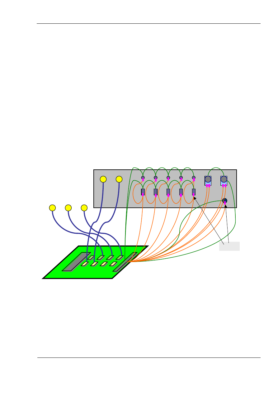
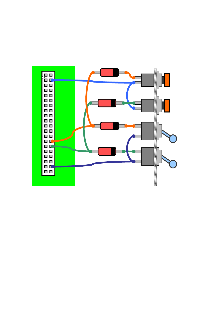
Below is simplified wiring layout diagram should a Key Matrix board not be used and all
controls are directly connected to the MJoy16 board:
15
As you see in the diagram above you must form a wiring matrix of all buttons and
switches directly on the panel plus soldering the diodes to each digital control.
Diodes
Simulator cockpit panel
Trim pots
MJoy16 board
Joystick and rudder
pots
Pushbuttons Rotary
switches
Toggle switches
“Init” button
MJoy16-C1 User’s Manual
www.mindaugas.com
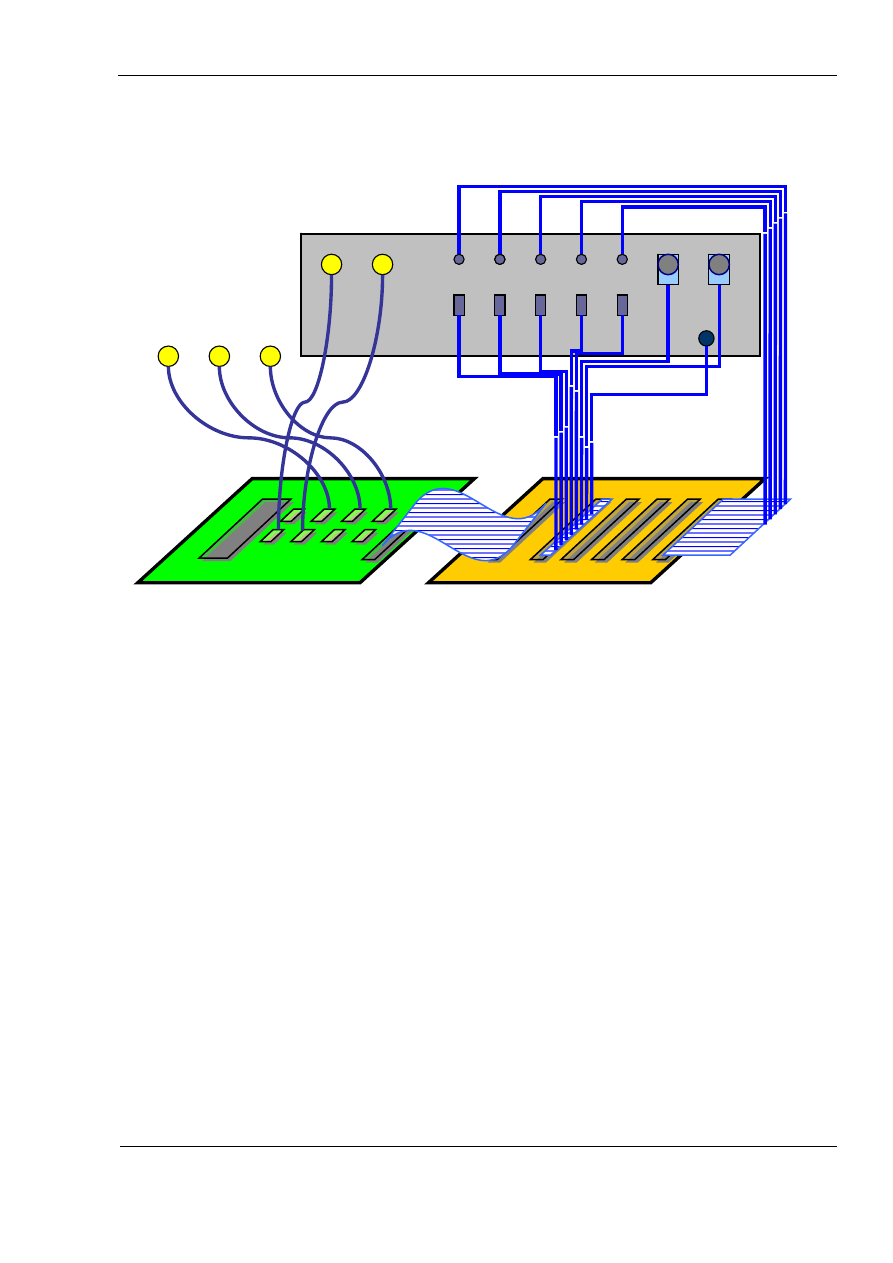
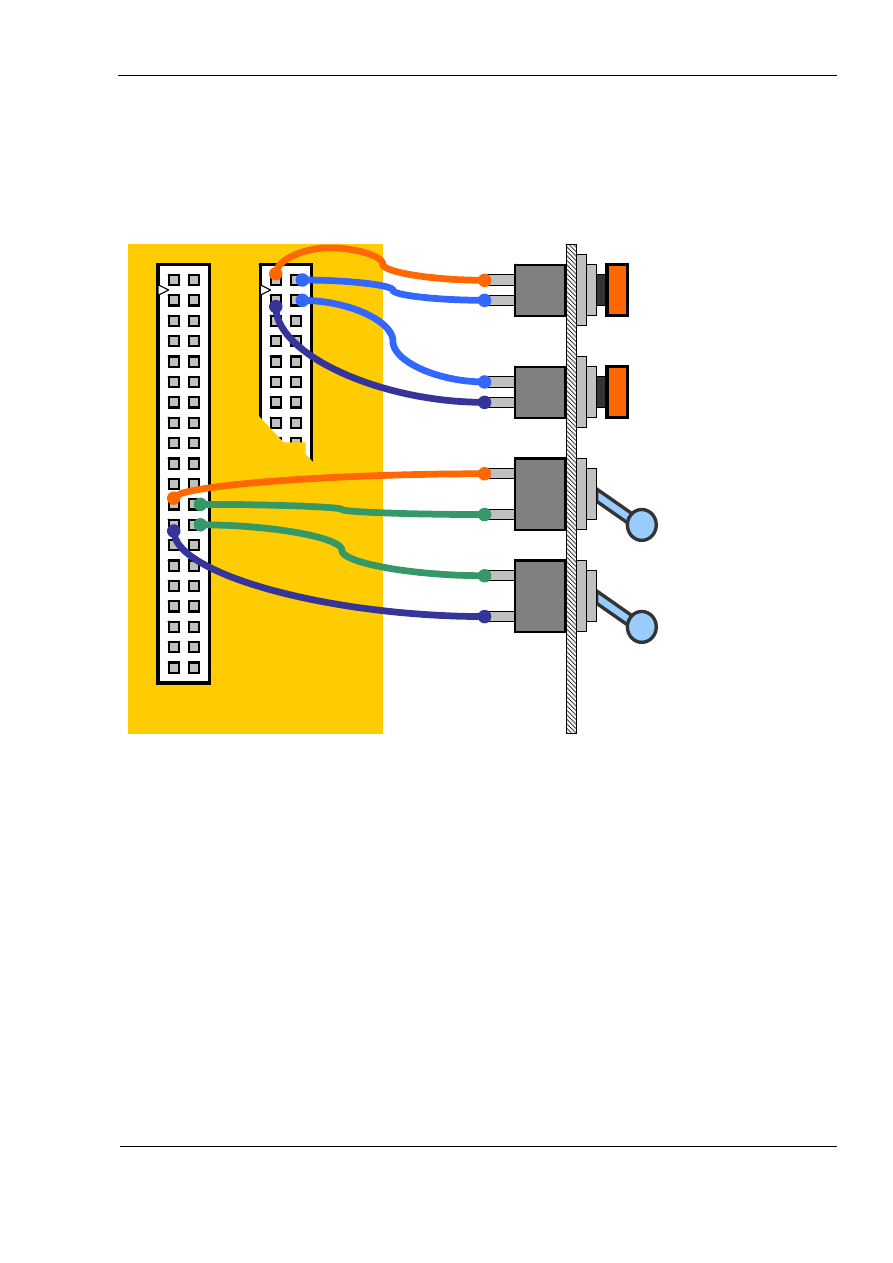
Below is a simplified example of cockpit panel wiring when using Key Matrix
board:
16
In this layout all wires can be laid out as a bundle along the edges of the panel. This
provides easy maintenance access to all buttons and switches.
Simulator cockpit panel
Trim pots
MJoy16 board
Joystick and rudder
pots
Rotary switches
Toggle switches
Key Matrix board
Pushbuttons
“Init” button
MJoy16-C1 User’s Manual
www.mindaugas.com
Wiring potentiometers and other analogue sensors
Analogue controls are usually standard linear potentiometers. The value of
potentiometers may be different but not less than 10 kOhm. Choosing a potentiometer
value is a matter of compromise. Smaller values will give better noise characteristics but
will draw more current from USB power supply. Greater values will put fewer loads on
USB power supply but will be more subject to noise and inter-axis interference.
For example 10k pot will have very good noise characteristics but will draw a 0.5
miliAmperes current per each axis. A 100k pot will draw only 0.05 miliAmperes but will
be a bit more sensitive to external noise and interference.
As a general rule any linear pot in the range between 10k and 100k should do well with
barely noticeable differences.
Analogue sensors can be any sensors providing an output voltage between 0 and +5V.
In most cases it is required to have a linear sensor output to get linear response over
the full movement range.
Sensors should be connected using shielded cable. Suggested type of cable for this is
microphone cable. They have two wires surrounded by a shield. Inside wires are usually
coloured white and red. Shield is connected to the ground (GND), red wire to +5V and
white to the signal terminal.
In case of rotary potentiometers the middle pin is always the slider, the signal output. If
you are using a sliding potentiometer, the slider pin position depends on type of the
potentiometer used.
If you are using other type of sensors, please consult the sensor documentation about
pin-out and operation of the specific sensor. Many sensors have GND and +5V for
power supply and one pin as a signal output. Connect them accordingly.
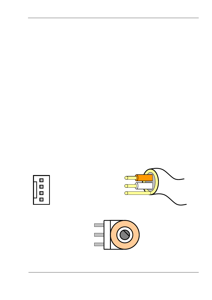
Below are the pictures of the connector of analogue input, shielded cable and
potentiometer:
+5V
1 – Signal
Signal
2 – GND
3 – Not connected
GND
4 – +5V
Shielded microphone
cable
Analog connector
on MJoy16
+5V
Si
gnal
GND
Potentiometer
17
It is recommended to connect potentiometer using shielded cable as short as possible.

MJoy16-C1 User’s Manual
www.mindaugas.com
18
.
If you are not using some of the axes then connect their signal terminal to the ground
Otherwise unconnected inputs may generate random inputs that might be induced from
other inputs, external signals etc.
MJoy16-C1 User’s Manual
www.mindaugas.com
Wiring digital controls
Digital controls are connected using unshielded wires. General recommendation to use
wires as short as possible still applies. Depending on whether you use Key Matrix board
or not wiring will be different.
About use of diodes and their polarity
All diodes shown in below sections are required to eliminate so-called “Phantom-
Buttons” effect which occurs in matrix key layouts when three or more buttons are
pressed simultaneously. They are already included on the Key Matrix board. If you are
using the Key Matrix board then don’t bother reading this section.
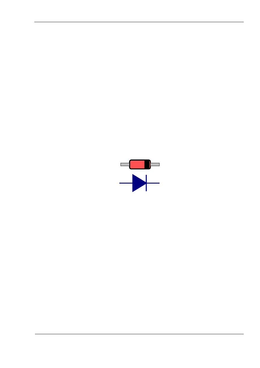
The diodes shown are widely popular 1N4148 but may be any other type of low power
fast switching diodes.
Since diodes are asymmetric devices it does matter which way you connect them. The
black band shown on the diode in below illustration corresponds to polarity marking of
1N4148:
Diode 1N4148
This band colour may be other colour depending on typical body colour of the diode.
Other types may have different marking convention.
If you are not sure about the polarity of diodes you have you can easily test find this out
by simple test described below:
1. Connect MJoy16 to PC via USB cable. Don’t connect any digital controls yet.
Make sure that Windows has installed the MJoy16 and open Game Controllers
panel for “MJ16”. This is done via Control Panel in Windows.
2. Take two wires Row A and Column 1 from MJoy16 digital inputs connector.
When you connect these two wires together you should see Button 1 lighting up
on “MJ16” panel.
3. Place the diode you have between these two wires in one or other way. When
Button 1 lights up again make a note of the diode marking and remember this
position as a reference.
4. When wiring all other controls use this reference to place all other diodes the
same way.
19
MJoy16-C1 User’s Manual
www.mindaugas.com
Wiring digital controls without Key Matrix board
If you don’t use Key Matrix board you will have to solder diodes directly to pushbuttons
and switches. These diodes are necessary to avoid so-called “Phantom Buttons”
presses. They should be soldered directly next to each button control. Below are some
examples how pushbuttons and toggle switches are wired directly to MJoy16 board:
Pushbutton E7
Row E
Pushbutton E5
20
It can be seen that a lot of soldering is made directly to the panel and there are wires
that are going from one control or diode to another. With more controls this complexity
increases even more. Different types of digital controls are wired in slightly different
ways. Exact wiring of them will be described further in this chapter. Key Matrix greatly
simplifies wiring and possible rewiring of the panel.
Toggle
Switch I7
Toggle
Switch I5
Panel
Diodes 1N4148
Digital Inputs
Row I
Column 5
Column 7
MJoy16 board
MJoy16-C1 User’s Manual
www.mindaugas.com
Wiring digital controls with Key Matrix board
When wiring with Key Matrix board wires from buttons and switches go directly to digital
input connectors on Key Matrix board. An example of wiring pushbuttons and toggle
switches is shown below:
21
Pushbutton C2
Toggle
Switch I4
Toggle
Switch I5
Digital Inputs 2
Digital Inputs 3
Panel
Pushbutton C1
Column 1
C1
C2
Row C
Row C
Column 2
Column 4
Row I
I4
I5
Row I
Column 5
Key Matrix board
MJoy16-C1 User’s Manual
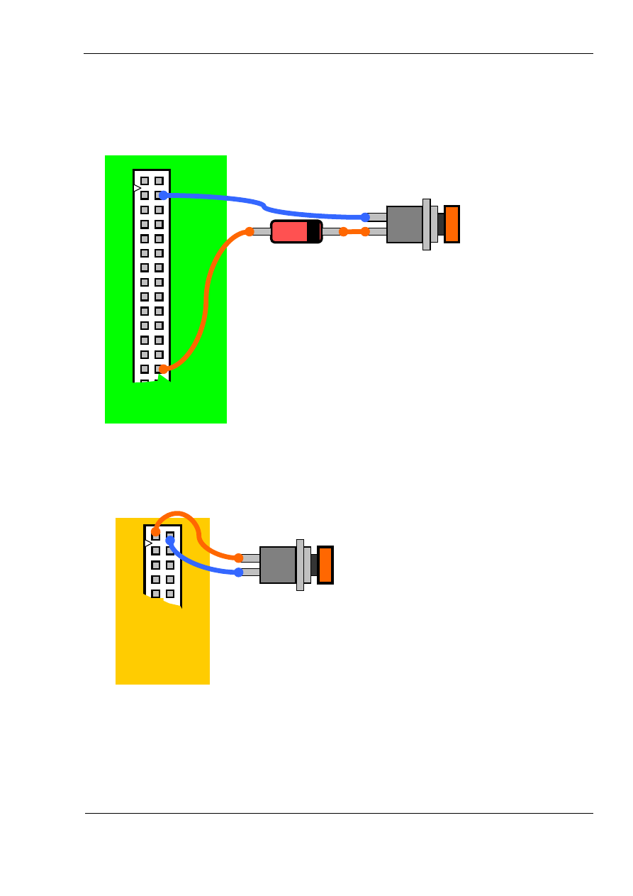
www.mindaugas.com
Wiring pushbuttons
If you don’t use Key Matrix board you will need to solder a diode in series to one of the
pushbutton pins. A wiring example is shown below:
Row E
Pushbutton E7
Digital Inputs
Diode 1N4148
Wiring pushbutton
directly to MJoy16
board
MJoy16 board
Pushbutton wiring example with Key Matrix board is shown below:
22
Note that no diode is needed as it is already included in Key Matrix board.
Digital Inputs 3
C1
Pushbutton C1
Key Matrix
board
Wiring pushbutton to
Key Matrix board
MJoy16-C1 User’s Manual
www.mindaugas.com
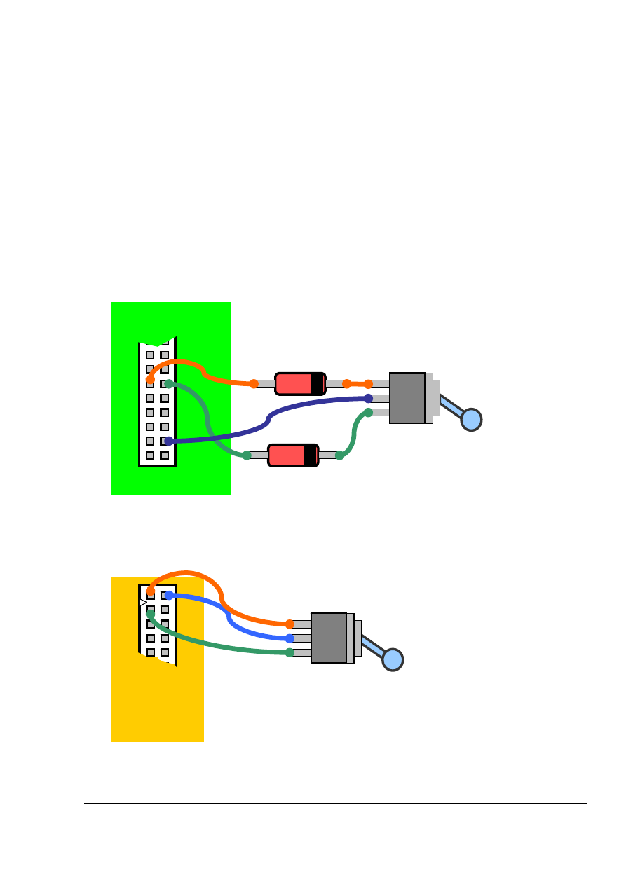
Wiring toggle switches
Toggle switches can be single throw or double throw. MJoy16-C1 is mainly designed for
single throw toggle switches but double throw toggles may also be used if required by
your cockpit application.
Single throw toggle switches have two positions: “On” and “Off”. Single throw toggle
switches are wired exactly as pushbuttons so please refer to pushbutton wiring
description for wiring the single throw toggle switch.
Double throw toggle switches have three positions: “On1”, “Off” and “On2”. “Off” is the
middle position. These toggle switches use 2 pairs of contacts on keys matrix. The
principle of connecting them is that common pin is connected to Column signal wire and
the other two pins are connected to different Row signal wires. Below is example of
wiring double throw toggle switch without Key Matrix board:
23
Below is an example of a double throw toggle switch wiring to the Key Matrix board
Please note that in above diagram wire from pin 4 (next to green wire) of digital inputs
was not used. This is because pins 2 and 4 are already interconnected on the connector
so extra 4
th
wire is not needed.
Digital Inputs 2
J1
Key Matrix
board
Wiring double throw
toggle switch to Key
Matrix board
Toggle
Switch J56
J2
Double throw
toggle switch I56
Diodes 1N4148
Digital Inputs
Column 6
MJoy16 board
Column 5
Row I
MJoy16-C1 User’s Manual
www.mindaugas.com
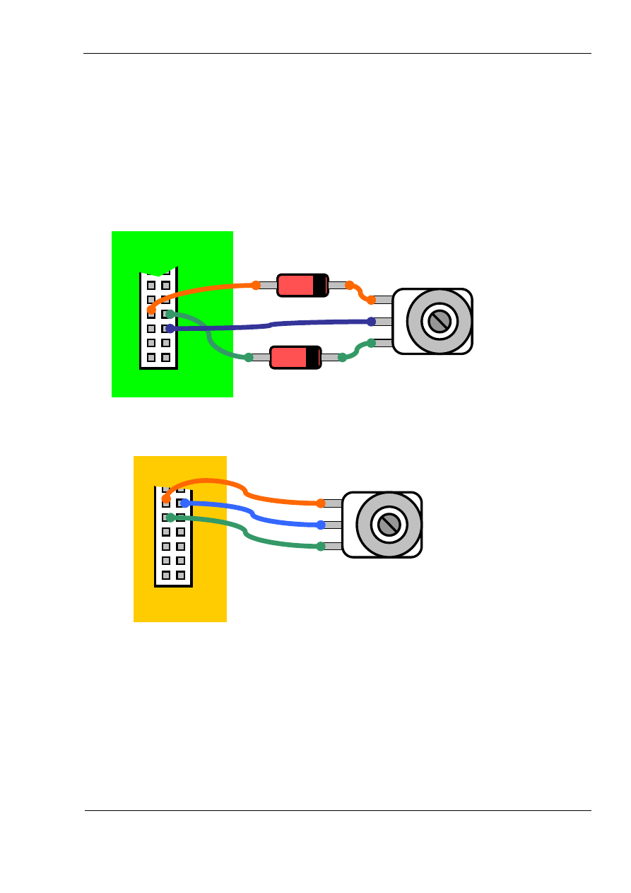
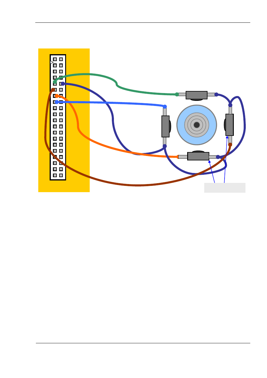
Wiring rotary switches
Wiring of phase shifted rotary switches is similar to wiring of double throw toggle
switches. The first thing is to find out which pin on the rotary switch is common. Its
position depends on the type of rotary. On some rotary switches it may be in the middle
but some may have it on one side.
Below is an example how to directly wire a rotary switch to the MJoy16 board:
Rotary
Diodes 1N4148
24
If you wire rotary switch through Key Matrix board you should follow the example below:
Digital Inputs 1
Key Matrix
board
Rotary
Switch K78
K7
K8
Wiring rotary switch to Key Matrix
board
Switch K12
Digital Inputs
MJoy16 board
Column 1
Column 2
Common
Row K
Wiring rotary switch to MJoy16
board
MJoy16-C1 User’s Manual
www.mindaugas.com
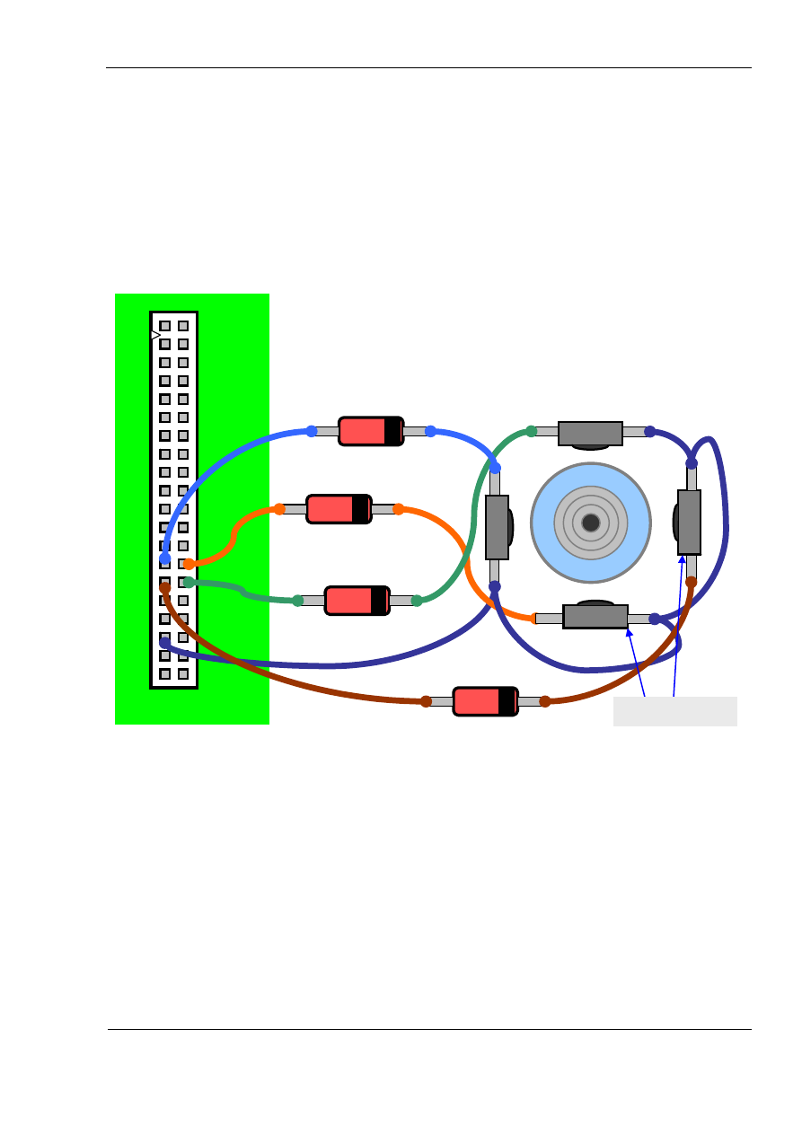
Wiring Hat switch
Hat switch is 8-way hat switch and it is made of 4 microswitches arranged on 4 sides of
hat switch enclosure. A small joystick handle presses one or two switches at a time
depending on angle of deflection. When only one switch is pressed it gives four main
directions at 90 degrees angles: “UP”, “RIGHT”, “DOWN” and “LEFT”. When two
switches are pressed it gives intermediate directions: “UP-RIGHT”, “UP-LEFT”, “DOWN-
RIGHT” and “DOWN-LEFT”.
Below is a diagram showing how to wire the hat switch directly to the MJoy16 board:
25
Diodes 1N4148
Digital Inputs
Row L
Column 8
Column 5
Hat switch
MJoy16 board
Column 7
Column 6
UP
LEFT
RIGHT
DOWN
Microswitches
MJoy16-C1 User’s Manual
www.mindaugas.com
Below is a diagram showing how to wire hat switch to the Key Matrix board:
Digital Inputs 1
Column 5
26
Row L
Column 8
Key Matrix board
Column 7
Column 6
Hat switch
UP
RIGHT
LEFT
DOWN
Microswitches

MJoy16-C1 User’s Manual
www.mindaugas.com
Wiring “Init” button
The Init button is wired the same way as any other pushbutton. Refer to the wiring in the
pushbutton section for information how to wire the “Init” button.
Wiring “Mode” and “Centre” switches
These switches set the mode of operation of MJoy16-C1. This mode is usually set
during the installation phase and never needs to be changed unless some cockpit
rework is to be done. So they may be placed somewhere inside of the panel as user do
not need to change them at any time during operation. These switches may also be
substituted by simple shorted or open pair of wires which resembles to “On” or “Off”
state of the switches. They might also be jumpers. On the Key Matrix board you may
short contact pairs L2 and/or L3 or leave them open. If you don’t use the Key Matrix
board you must connect the contacts via diode as if using a simple pushbutton.
27
MJoy16-C1 User’s Manual
www.mindaugas.com
Controls Mapping
MJoy16-C1 has two modes of mapping controls. They differ from each other by the
numbering of buttons assigned to pushbuttons, toggle switches and rotary switches.
Mapping Mode 1 puts pushbuttons first, toggle switches next and rotary switches last.
Mapping Mode 2 is basically bottom-up version of this layout. It puts rotary switches
first, toggle switches next and pushbuttons last.
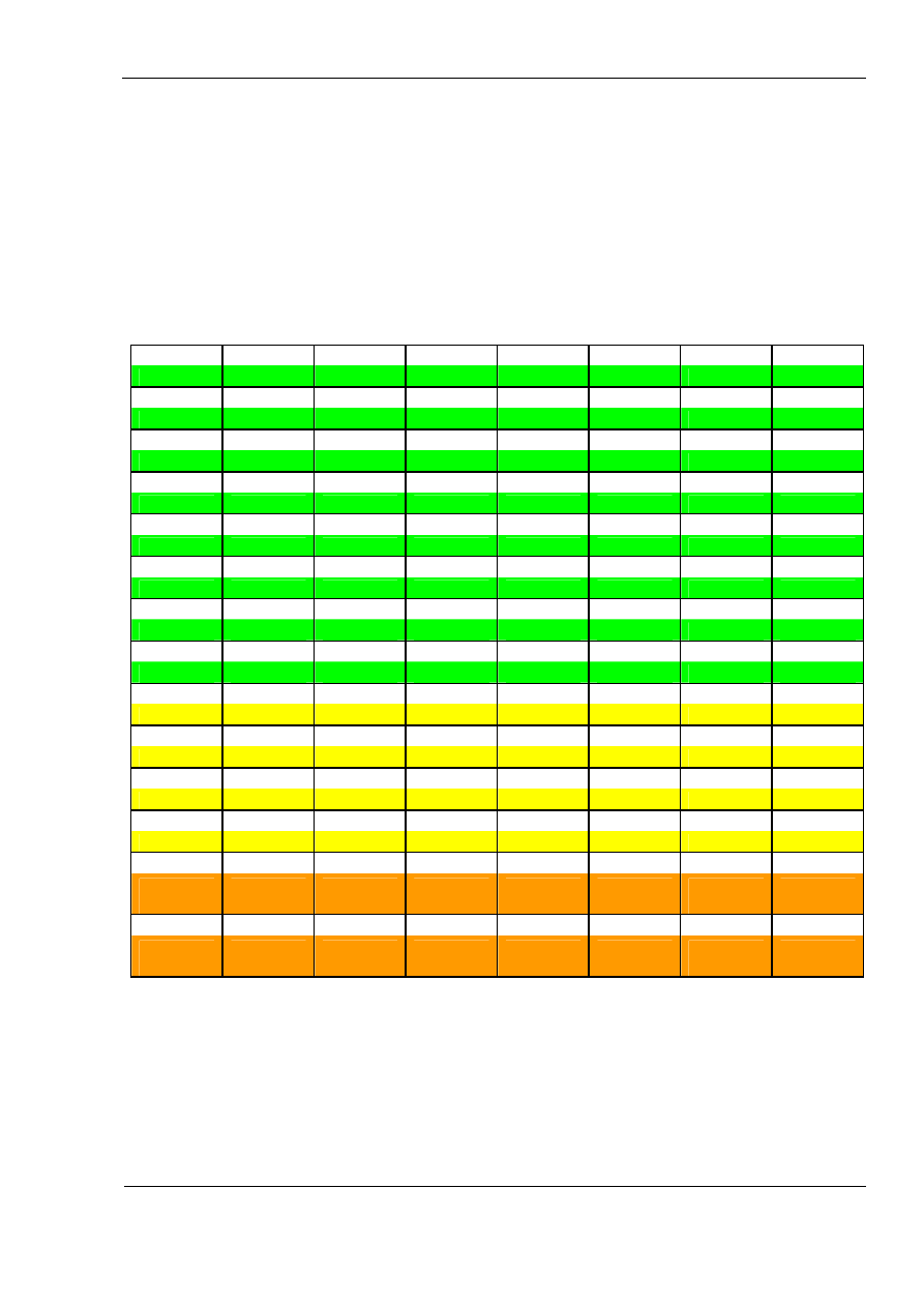
Below is the table of mapping of controls in Mode 1:
1 2 3 4 5 6 7 8
Btn A1
Btn A2
Btn A3
Btn A4
Btn A5
Btn A6
Btn A7
Btn A8
9 10 11 12 13 14 15 16
Btn B1
Btn B2
Btn B3
Btn B4
Btn B5
Btn B6
Btn B7
Btn B8
17 18 19 20 21 22 23 24
Btn C1
Btn C2
Btn C3
Btn C4
Btn C5
Btn C6
Btn C7
Btn C8
25 26 27 28 29 30 31 32
Btn D1
Btn D2
Btn D3
Btn D4
Btn D5
Btn D6
Btn D7
Btn D8
33 34 35 36 37 38 39 40
Btn E1
Btn E2
Btn E3
Btn E4
Btn E5
Btn E6
Btn E7
Btn E8
41 42 43 44 45 46 47 48
Btn F1
Btn F2
Btn F3
Btn F4
Btn F5
Btn F6
Btn F7
Btn F8
49 50 51 52 53 54 55 56
Btn G1
Btn G2
Btn G3
Btn G4
Btn G5
Btn G6
Btn G7
Btn G8
57 58 59 60 61 62 63 64
Btn H1
Btn H2
Btn H3
Btn H4
Btn H5
Btn H6
Btn H7
Btn H8
65 66 67 68 69 70 71 72
Tgl I1 On
Tgl I2 On
Tgl I3 On
Tgl I4 On
Tgl I5 On
Tgl I6 On
Tgl I7 On
Tgl I8 On
73 74 75 76 77 78 79 80
Tgl I1 Off
Tgl I2 Off
Tgl I3 Off
Tgl I4 Off
Tgl I5 Off
Tgl I6 Off
Tgl I7 Off
Tgl I8 Off
81 82 83 84 85 86 87 88
Tgl J1 On
Tgl J2 On
Tgl J3 On
Tgl J4 On
Tgl J5 On
Tgl J6 On
Tgl J7 On
Tgl J8 On
89 90 91 92 93 94 95 96
Tgl J1 Off
Tgl J2 Off
Tgl J3 Off
Tgl J4 Off
Tgl J5 Off
Tgl J6 Off
Tgl J7 Off
Tgl J8 Off
97 98 99 100 101 102 103 104
Rot K12
CW
Rot K12
CCW
Rot K34
CW
Rot K34
CCW
Rot K56
CW
Rot K56
CCW
Rot K78
CW
Rot K78
CCW
105 106 107 108 109 110 111 112
Rot K12
FCW
Rot K12
FCCW
Rot K34
FCW
Rot K34
FCCW
Rot K56
FCW
Rot K56
FCCW
Rot K78
FCW
Rot K78
FCCW
Bold numbers in above table show button number as it is seen by Windows. These are
the same numbers which are seen in joystick control panel from game controllers menu.
Mnemonics in the table mean following: Btn – pushbutton, Tgl – toggle switch, Rot –
rotary switch, CW – clockwise, CCW – counter-clockwise, FCW – fast clockwise, FCCW
– fast counter-clockwise.
For example Pushbutton A3 acts like a joystick Button 3 in Windows. When you switch
toggle switch J6 to “On” position it generates joystick Button 86 brief press. When you
28
MJoy16-C1 User’s Manual
www.mindaugas.com
slowly rotate rotary switch K12 clockwise it generates joystick Button 97 press pulses in
Windows. If you quickly rotate the same K12 rotary switch in counter-clockwise direction
it will generate joystick Button 106 presses.
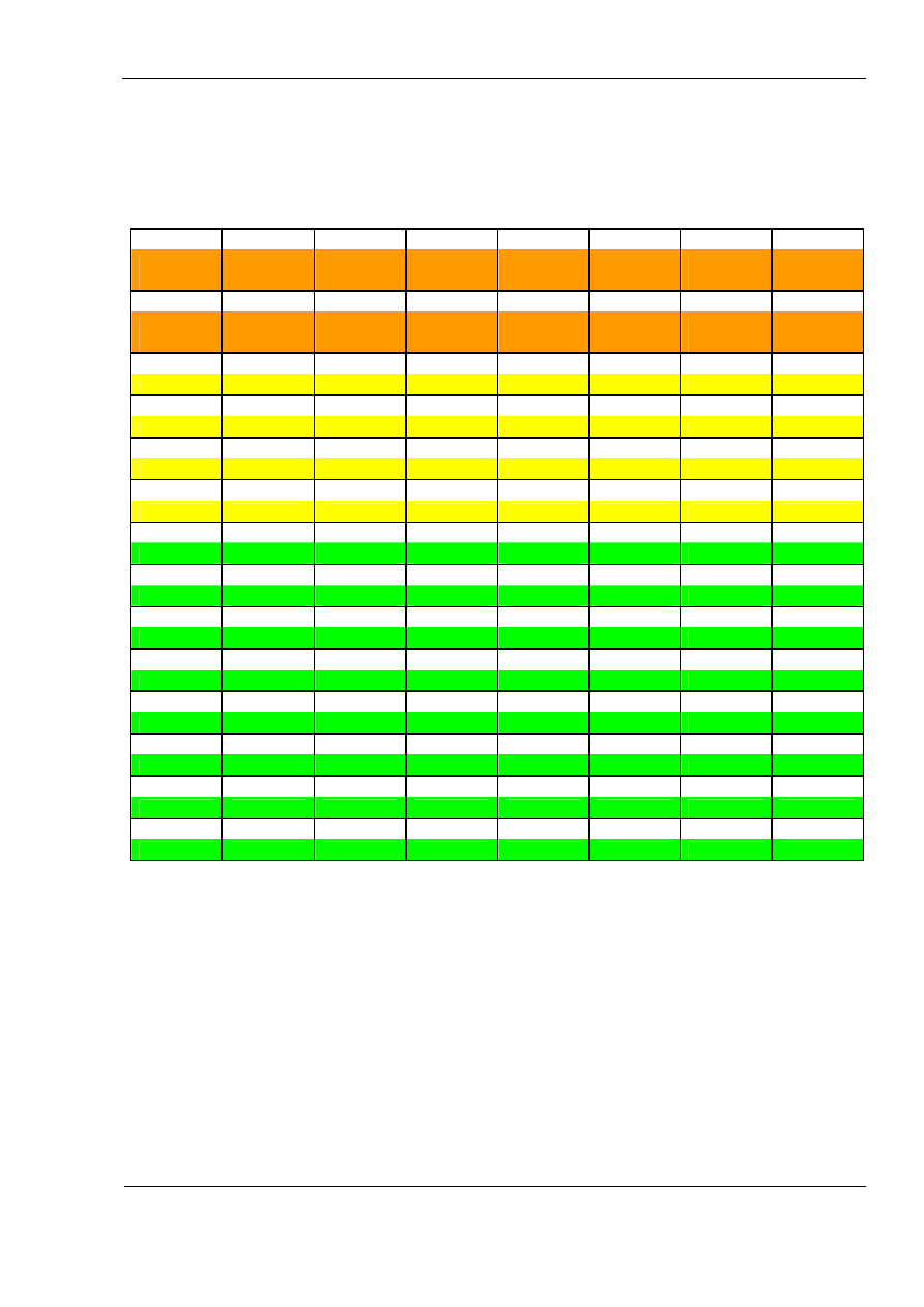
If you select Mode2 you will have controls mapping as shown in table below:
1 2 3 4 5 6 7 8
Rot K12
CW
Rot K12
CCW
Rot K34
CW
Rot K34
CCW
Rot K56
CW
Rot K56
CCW
Rot K78
CW
Rot K78
CCW
9 10 11 12 13 14 15 16
Rot K12
CW
Rot K12
CCW
Rot K34
CW
Rot K34
CCW
Rot K56
CW
Rot K56
CCW
Rot K78
CW
Rot K78
CCW
17 18 19 20 21 22 23 24
Tgl I1 On
Tgl I2 On
Tgl I3 On
Tgl I4 On
Tgl I5 On
Tgl I6 On
Tgl I7 On
Tgl I8 On
25 26 27 28 29 30 31 32
Tgl I1 Off
Tgl I2 Off
Tgl I3 Off
Tgl I4 Off
Tgl I5 Off
Tgl I6 Off
Tgl I7 Off
Tgl I8 Off
33 34 35 36 37 38 39 40
Tgl J1 On
Tgl J2 On
Tgl J3 On
Tgl J4 On
Tgl J5 On
Tgl J6 On
Tgl J7 On
Tgl J8 On
41 42 43 44 45 46 47 48
Tgl J1 Off
Tgl J2 Off
Tgl J3 Off
Tgl J4 Off
Tgl J5 Off
Tgl J6 Off
Tgl J7 Off
Tgl J8 Off
49 50 51 52 53 54 55 56
Btn A1
Btn A2
Btn A3
Btn A4
Btn A5
Btn A6
Btn A7
Btn A8
57 58 59 60 61 62 63 64
Btn B1
Btn B2
Btn B3
Btn B4
Btn B5
Btn B6
Btn B7
Btn B8
65 66 67 68 69 70 71 72
Btn C1
Btn C2
Btn C3
Btn C4
Btn C5
Btn C6
Btn C7
Btn C8
73 74 75 76 77 78 79 80
Btn D1
Btn D2
Btn D3
Btn D4
Btn D5
Btn D6
Btn D7
Btn D8
81 82 83 84 85 86 87 88
Btn E1
Btn E2
Btn E3
Btn E4
Btn E5
Btn E6
Btn E7
Btn E8
89 90 91 92 93 94 95 96
Btn F1
Btn F2
Btn F3
Btn F4
Btn F5
Btn F6
Btn F7
Btn F8
97 98 99 100 101 102 103 104
Btn G1
Btn G2
Btn G3
Btn G4
Btn G5
Btn G6
Btn G7
Btn G8
105 106 107 108 109 110 111 112
Btn H1
Btn H2
Btn H3
Btn H4
Btn H5
Btn H6
Btn H7
Btn H8
In this mode advanced controls are arranged at the beginning of buttons range. This
provides some advantage when setting up this joystick in Windows because some
Windows games have limitations. Possible ways of overcoming these limitations is
described in next chapter about setting up MJoy16-C1 in Windows environment.
29

MJoy16-C1 User’s Manual
www.mindaugas.com
Setting up MJoy16-C1 in Windows
About limitation of 32 buttons per joystick
This joystick controller has 112 buttons. This number of buttons is supported by recent
Windows and DirectX versions. Older versions of Windows supported only up to 32
buttons per joystick device. This limitation was removed by introducing alternative
DirectX version 5 and newer interface to joysticks. This enables all contemporary
programs to process more than 32 buttons from single joystick.
Yet still some games use old interface to joystick and thus have limitation of 32 buttons
per joystick device. One example of such games is Microsoft Flight Simulator 2004
(MSFS) which – unfortunately - still has this limitation.
This was the reason of introducing two controls mapping modes. If your priority is to use
rotary and toggle switches of MJoy16-C1 then you should use mapping mode 2. In this
mode you will be able to use rotary switches and first 8 toggle switches directly from
simulator software. Otherwise you may use mode 1 which places 32 pushbuttons in the
first rows.
Mapping modes concept will work even better if you will use several MJoy16-C1
controllers. Then some controllers may be set to mode 1 and some to mode 2.
For example if you have two MJoy16-C1 sets, you can use the first set in mode 1 and
the second set in mode 2. This will allow you to use 32 pushbuttons, 4 rotary switches
and 8 toggle switches directly from Microsoft Flight Simulator.
There is another possibility to use all buttons from on MJoy16-C1. To be able to use all
112 buttons in MSFS you should use some software which translates joystick button
presses to keyboard key presses. One example is described in next section.
Translating joystick buttons to keyboard keys
There are programs which can translate joystick buttons to keyboard key presses. As
these programs and their availability is rapidly changing please see MJoy16-C1 product
page on
http://www.mindaugas.com
website. Known available options will be listed
there.
30

MJoy16-C1 User’s Manual
www.mindaugas.com
Multiple joysticks in Windows
First of all it is perfectly possible to have several joysticks or other game controller
devices connected to the same computer. USB HID drivers allow up to 16
simultaneously operating gaming devices. You can still use your favourite joystick and
have multiple MJoy16-C1 boards connected together.
All connected gaming input devices appear in Windows “Game Controllers” panel list in
some order. Newly discovered devices are placed in certain list position automatically.
The order of devices in this list is important when you setup joystick controls in your
favourite simulator game. Normally you would prefer to have your main joystick first on
the list, secondary – second and so on.
Unfortunately current Windows versions including Windows XP SP2 and older don’t
allow you to change this list order. There is a chance that Microsoft might implement
this capability in their later Windows versions but for now we must live with that.
This order depends on internal identifier numbers of gaming devices. These identifiers
are Vendor ID and Product ID. These two IDs identify different Plug-and-Play devices
from various manufacturers. Certain Vendor IDs are assigned to each vendor. All
different products from one vendor will have the same Vendor ID but they will have
different Product IDs.
The order of gaming devices in “Game Controllers” panel list is arranged in ascending
Vendor ID and then Product ID order. That’s why Thrustmaster Afterburner joystick will
always be above Logitech Wingman series joysticks and Thrustmaster Top Gun (R)
Afterburner will be above Thrustmaster Top Gun (R) Fox2 Pro joystick.
Fortunately for us we can choose Vendor ID and Product ID whichever we like. MJoy16-
C1 just as later MJoy versions by default uses Vendor ID = 0 which puts these MJoys
on top of the list.
MJoy16-C1 controllers are available in several modifications which differ by Vendor ID,
Product ID and the Product Name which appears in “Game Controllers” list. First
modification name is “MJ16”. This is the default modification which should be installed if
you use only one MJoy16-C1 in your cockpit. Other modifications are named “MJ62”,
“MJ63” and so on. They will appear in Windows in corresponding order:
MJ16
MJ62
MJ63
....
If you already have “MJ16” (this is default) modification in your cockpit and you want to
expand it with another MJoy16-C1 controller you should order “MJ62” modification. If
you are expanding even further you should go for “MJ63” and so on.
It is possible to program MJoy16 to have your custom IDs and name. The procedure
how to change Vendor ID, Product ID and Product Name of MJoy16-C1 is included in
“Programming MJoy16-C1” manual which is located on
http://www.mindaugas.com
website in MJoy16-C1 product section. Programming is more advanced and complex
procedure and it was left out of scope of this manual.
31

MJoy16-C1 User’s Manual
www.mindaugas.com
Credits
Very big Thank You to Jan L. F. Bos for his great help on this project!
Legal
MJoy16-C1 User’s Manual Copyright (C) 2005 Mindaugas Milasauskas,
mindaug@mindaugas.com
MJoy, MJoy16, Key Matrix and MJoy16-C1 are Copyright (C) Mindaugas Milasauskas,
mindaug@mindaugas.com
Windows(TM), Windows XP(TM), DirectX and(TM) Microsoft Flight Simulator(TM) are
Copyright (C) Microsoft Corporation. All rights reserved.
Thrustmaster(TM), Top Gun (R) are Copyright (C) Thrustmaster Corporation. All rights
reserved.
Logitech (TM), Logitech Wingman (R) are Copyright (C) Logitech Corporation. All rights
reserved.
32

MJoy16-C1 User’s Manual
www.mindaugas.com
Appendixes
A1. MJoy16-C1 wiring schematic diagram without Key Matrix board
Schematic diagram of wiring MJoy16-C1 controls directly to the MJoy16 board is
displayed on the next page.
33
Row A
Co
lu
mn
1
A1
I1
A2
A3
A4
A5
A6
A7
A8
B1
B2
B3
B4
B5
B6
B7
B8
C1
C2
C3
C4
C5
C6
C7
C8
D1
D2
D3
D4
D5
D6
D7
D8
E1
E2
E3
E4
E5
E6
E7
E8
F1
F2
F3
F4
F5
F6
F7
F8
G1
G2
G3
G4
G5
G6
G7
G8
H1
H2
H3
H4
H5
H6
H7
H8
Co
lu
mn
2
Co
lu
mn
3
Row B
Row C
Row D
Row E
Row F
Row G
Row H
Co
lu
mn
4
Co
lu
mn
5
Co
lu
mn
6
Co
lu
mn
7
Co
lu
mn
8
Row I
I2
I3
I4
I5
I6
I7
I8
J1
Row J
J2
J3
J4
J5
J6
J7
J8
Row K
1
2
3
4
5
6
7
8
9
10
11
12
13
14
15
16
17
18
19
20
21
22
23
24
25
26
27
28
29
30
31
32
33
34
35
36
37
38
39
40
1
Common
2
3
Rotary Switch
K12
1
Common
2
3
Rotary Switch
K34
1
Common
2
3
Rotary Switch
K56
1
Common
2
3
Rotary Switch
K78
L2
Jumper
L1
L3
Jumper
Row L
"Init" button
"Mode"
"Centre"
Row G
Row E
Row C
Row A
Row H
Row F
Row D
Row B
Column 7
Column 5
Column 3
Column 1
Row K
Row I
Column 8
Column 6
Column 4
Column 2
Row L
Row J
Pu
sh
b
u
tt
o
n
s
T
o
g
g
le
S
w
it
ch
es
10...100K
R1
X potentiometer
Signal
1
GND
2
N.C.
3
+5V
4
JP1
X
10...100K
R2
Y potentiometer
Signal
1
GND
2
N.C.
3
+5V
4
JP2
Y
10...100K
R3
Z potentiometer
Signal
1
GND
2
N.C.
3
+5V
4
JP3
Z
10...100K
R4
Rx potentiometer
Signal
1
GND
2
N.C.
3
+5V
4
JP4
Rx
10...100K
R5
Ry potentiometer
Signal
1
GND
2
N.C.
3
+5V
4
JP5
Ry
10...100K
R6
Rz potentiometer
Signal
1
GND
2
N.C.
3
+5V
4
JP6
Rz
10...100K
R7
Slider potentiometer
Signal
1
GND
2
N.C.
3
+5V
4
JP7
Slider
10...100K
R8
Dial potentiometer
Signal
1
GND
2
N.C.
3
+5V
4
JP8
Dial
M
Joy
16
A
na
lo
g I
n
put
s c
o
nn
ec
to
rs
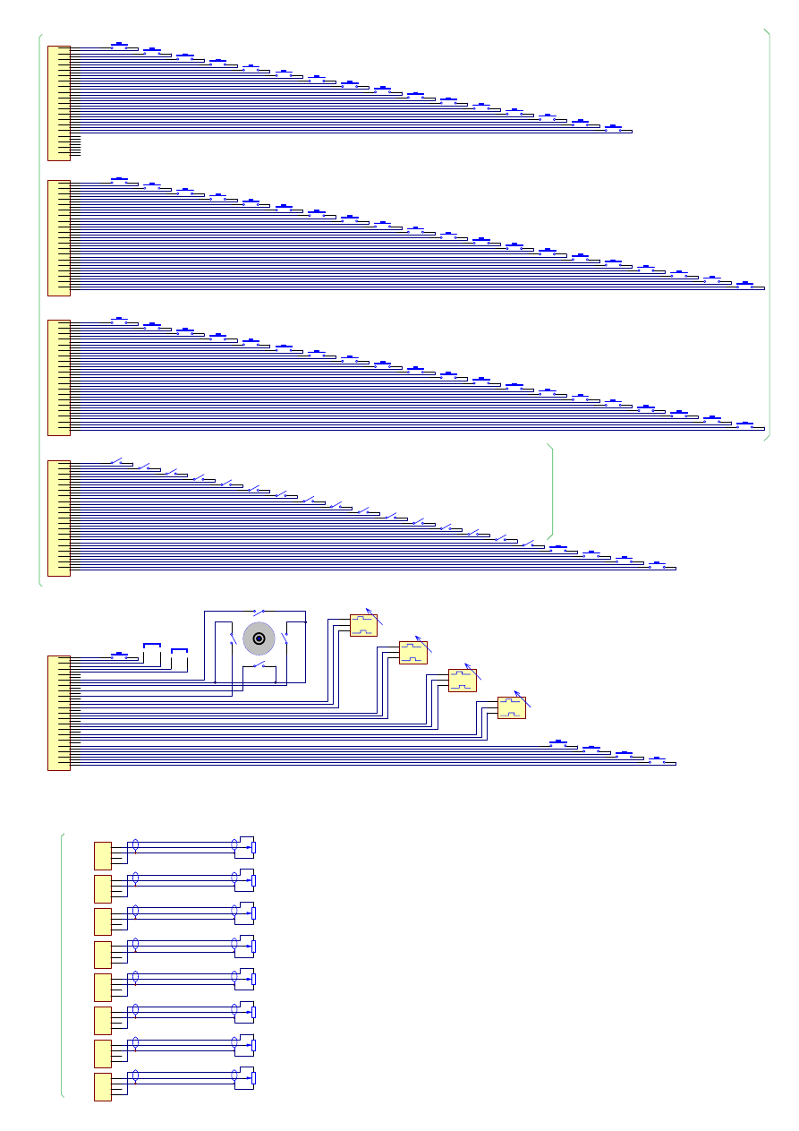
MJoy16 Digital Input Connector
Wiring MJoy16-C1 controls
directly to MJoy16 board
Copyright (C) 2005 Mindaugas Milasauskas,
mindaug@mindaugas.com http://www.mindaugas.com
UP
LEFT
RIGHT
DOWN
Hat Switch
All diodes are 1N4148 or other
type with similar characteristics

MJoy16-C1 User’s Manual
www.mindaugas.com
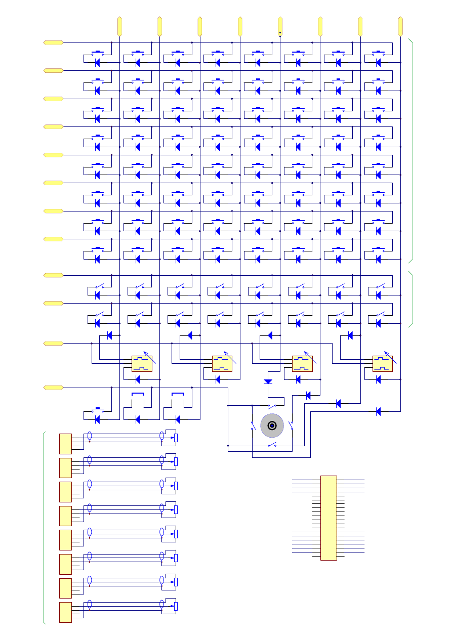
A2. MJoy16-C1 wiring diagram with Key Matrix board
Schematic diagram of wiring MJoy16-C1 controls to the Key Matrix board is displayed
on the next page.
35
A1
I1
A2
A3
A4
B1
B2
B3
B4
B5
B6
B7
B8
C1
C2
C3
C4
C5
C6
C7
C8
D1
D2
D3
D4
D5
D6
D7
D8
E1
E2
E3
E4
E5
E6
E7
E8
F1
F2
F3
F4
F5
F6
F7
F8
G1
G2
G3
G4
G5
G6
G7
G8
H1
H2
H3
H4
H5
H6
H7
H8
I2
I3
I4
I5
I6
I7
I8
J1
J2
J3
J4
J5
J6
J7
J8
1
Common
2
3
Rotary Sw itch
K12
1
Common
2
3
Rotary Sw itch
K34
1
Common
2
3
Rotary Sw itch
K56
1
Common
2
3
Rotary Sw itch
K78
L2
Jumper
L1
L3
Jumper
"Init" button
"Mode"
"Centre"
Pu
sh
b
u
tt
o
n
s
T
ogg
le
S
w
it
c
he
s
10...100K
R1
X potentiometer
Signal
1
GND
2
N.C.
3
+5V
4
JP1
X
10...100K
R2
Y potentiometer
Signal
1
GND
2
N.C.
3
+5V
4
JP2
Y
10...100K
R3
Z potentiometer
Signal
1
GND
2
N.C.
3
+5V
4
JP3
Z
10...100K
R4
Rx potentiometer
Signal
1
GND
2
N.C.
3
+5V
4
JP4
Rx
10...100K
R5
Ry potentiometer
Signal
1
GND
2
N.C.
3
+5V
4
JP5
Ry
10...100K
R6
Rz potentiometer
Signal
1
GND
2
N.C.
3
+5V
4
JP6
Rz
10...100K
R7
Slider potentiometer
Signal
1
GND
2
N.C.
3
+5V
4
JP7
Slider
10...100K
R8
Dial potentiometer
Signal
1
GND
2
N.C.
3
+5V
4
JP8
Dial
M
Jo
y1
6 A
n
a
lo
g
In
put
s
c
onn
ec
to
rs
Wiring MJoy16-C1 controls
to Key Matrix board
Copyright (C) 2005 Mindaugas Milasauskas,
mindaug@mindaugas.com http://www.mindaugas.com
UP
LEFT
RIGHT
DOWN
Hat Switch
1
2
3
4
5
6
7
8
9
10
11
12
13
14
15
16
17
18
19
20
21
22
23
24
25
26
27
28
29
30
31
32
33
34
35
36
37
38
39
40
Digital Inputs 3
1
2
3
4
5
6
7
8
9
10
11
12
13
14
15
16
17
18
19
20
21
22
23
24
25
26
27
28
29
30
31
32
33
34
35
36
37
38
39
40
Digital Inputs 4
1
2
3
4
5
6
7
8
9
10
11
12
13
14
15
16
17
18
19
20
21
22
23
24
25
26
27
28
29
30
31
32
33
34
35
36
37
38
39
40
Digital Inputs 5
1
2
3
4
5
6
7
8
9
10
11
12
13
14
15
16
17
18
19
20
21
22
23
24
25
26
27
28
29
30
31
32
33
34
35
36
37
38
39
40
Digital Inputs 2
A5
A6
A7
A8
1
2
3
4
5
6
7
8
9
10
11
12
13
14
15
16
17
18
19
20
21
22
23
24
25
26
27
28
29
30
31
32
33
34
35
36
37
38
39
40
Digital Inputs 1
K
e
y M
at
ri
x
bo
ar
d D
igi
ta
l
Inpu
ts
c
on
ne
ct
or
s
Document Outline
- Contents
- Disclaimer
- Introduction
- Controls
- Boards description
- Wiring MJoy16-C1
- Controls Mapping
- Setting up MJoy16-C1 in Windows
- Credits
- Legal
- Appendixes
Wyszukiwarka
Podobne podstrony:
73 Varia B231 POL manual v1
blizzer generator pradu users manual
07 Altivar11 A EU users manual
4CH 8CH ENGLISH MANUAL(v1
16 CH ENGLISH MANUAL(v1 0)
linux mandrake 8 1 users manual 3zyndeyhqooqyui2gqfop2orb3fn25dkbzr4wei 3ZYNDEYHQOOQYUI2GQFOP2ORB3FN
73 Varia B231 POL manual v1
Tauris Club Manual v1 4US
Dongle User Manual V1 3
MoTomagx user manual v1 1
pimpmyea com FuturoFX Users Manual
Auditor Pro Manual v1 0 5
MillipaK 4QPM Manual V1 01 (633T43801)
universal remote control 8 in 1 users manual 121714
MJoy16 C1 matrix
G Wiz MC Users Manual 1 1
więcej podobnych podstron