Chapter 5 Equilibrium 5-1
Chapter 5 Equilibrium
“Nature and Nature’s laws lay hid in night:
God said, Let Newton be! and all was light.”
Alexander Pope
5.1 The First Condition of Equilibrium
The simplest way to define the equilibrium of a body is to say that a body is in equilibrium if it has no
acceleration. That is, if the acceleration of a body is zero, then it is in equilibrium. Bodies in equilibrium under a
system of forces are described as a special case of Newton’s second law,
F = ma (4.9)
where F is the resultant force acting on the body. As pointed out in chapter 4, to emphasize the point that F is the
resultant force, Newton’s second law is sometimes written in the form
Σ F = ma
If there are forces acting on a body, but the body is not accelerated (i.e., a = 0), then the body is in equilibrium
under these forces and the condition for that body to be in equilibrium is simply
Σ F = 0 (5.1)
Equation 5.1 is called the first condition of equilibrium. The first condition of equilibrium states that for a body
to be in equilibrium, the vector sum of all the forces acting on that body must be zero. If the sum of the force vectors
are added graphically they will form a closed figure because the resultant vector, which is equal to the sum of all
the force vectors, is equal to zero.
Remember that if the acceleration is zero, then there is no change of the velocity with time. Most of the
cases considered in this book deal with bodies that are at rest (v = 0) under the applications of forces. Occasionally
we also consider a body that is moving at a constant velocity (also a case of zero acceleration). At first, we consider
only examples where all the forces act through only one point of the body. Forces that act through only one point of
the body are called concurrent forces. That portion of the study of mechanics that deals with bodies in equilibrium
is called statics. When a body is at rest under a series of forces it is sometimes said to be in static equilibrium.
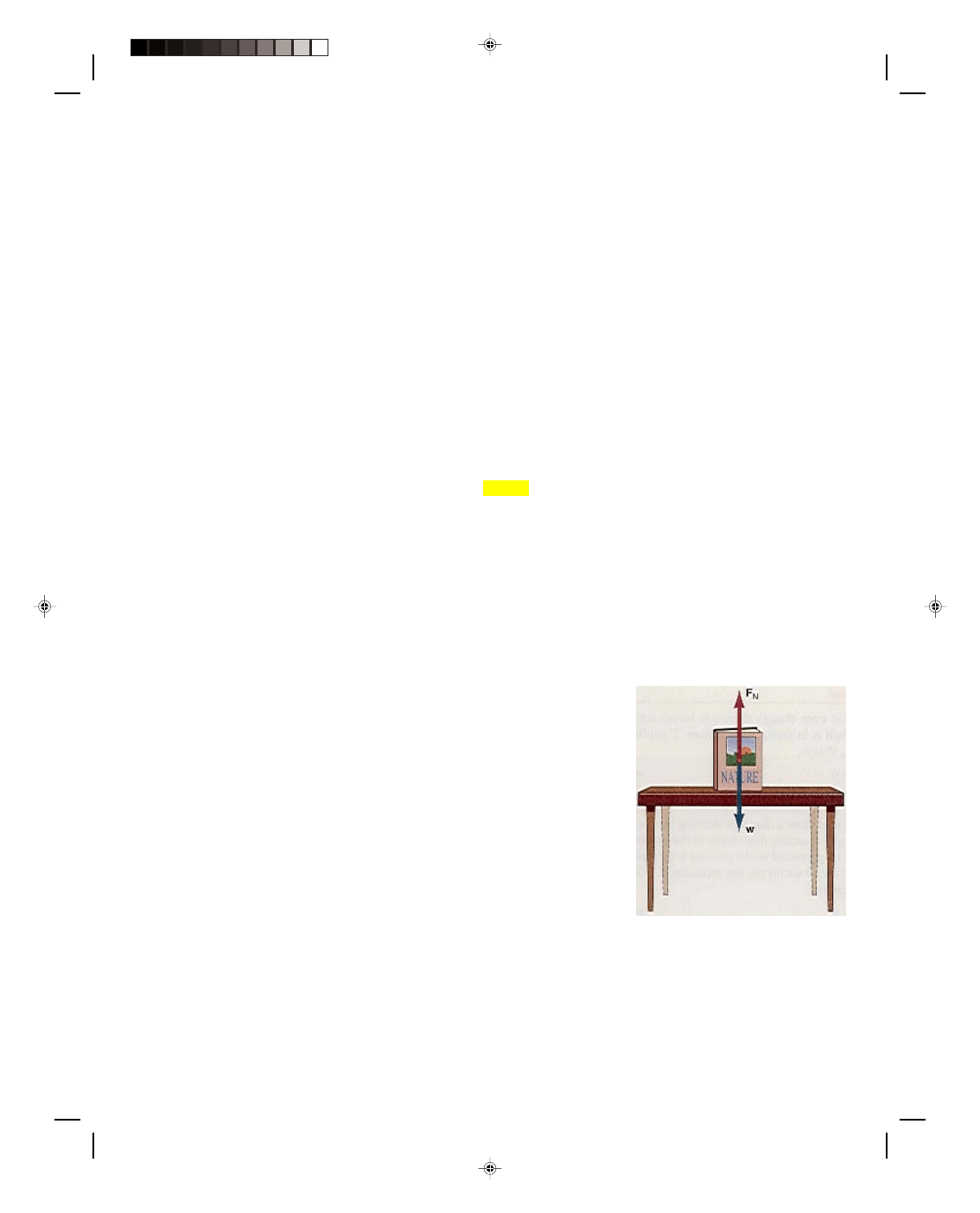
One of the simplest cases of a body in equilibrium is a book resting
on the table, as shown in figure 5.1. The forces acting on the book are its
weight w, acting downward, and F
N
, the normal force that the table exerts
upward on the book. Because the book is resting on the table, it has zero
acceleration. Hence, the sum of all the forces acting on the book must be
zero and the book must be in equilibrium. The sum of all the forces are
Σ F = F
N
+ w = 0
Taking the upward direction to be positive and the downward direction to
be negative, this becomes
F
N
− w = 0
Hence,
F
N
= w
That is, the force that the table exerts upward on the book is exactly equal
to the weight of the book acting downward. As we can easily see, this is
Figure 5.1
A body in equilibrium.
nothing more than a special case of Newton’s second law where the acceleration is zero. That is, forces can act on a
body without it being accelerated if these forces balance each other out.
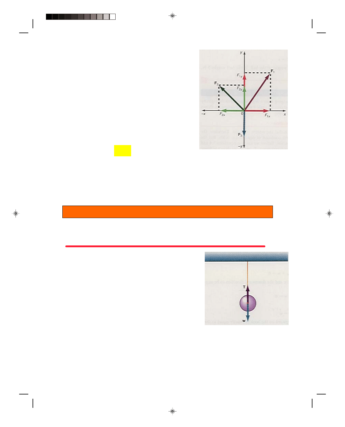
Let us consider another example of a body in equilibrium, as shown in figure 5.2. Suppose three forces F
1
,
F
2
, and F
3
are acting on the body that is located at the point 0, the origin of a Cartesian coordinate system. If the
Pearson Custom Publishing
139
5-2 Mechanics
body is in equilibrium, then the vector sum of those forces must add
up to zero and the body is not accelerating. Another way to observe
that the body is in equilibrium is to look at the components of the
forces, which are shown in figure 5.2. From the diagram we can see
that if the sum of all the forces in the x-direction is zero, then there
will be no acceleration in the x-direction. If the forces in the positive
x-direction are taken as positive, and those in the negative x-
direction as negative, then the sum of the forces in the x-direction is
simply
F
1x
− F
2x
= 0 (5.2)
Similarly, if the sum of all the forces in the y-direction is
zero, there will be no acceleration in the y-direction. As seen in the
diagram, this becomes
F
1y
+ F
2y
− F
3
= 0 (5.3)
A generalization of equations 5.2 and 5.3 is
Σ F
x
= 0 (5.4)
Σ F
y
= 0 (5.5)
Figure 5.2
Three forces in equilibrium.
which is another way of stating the first condition of equilibrium.
The first condition of equilibrium also states that the body is in equilibrium if the sum of all the forces in
the x-direction is equal to zero and the sum of all the forces in the y-direction is equal to zero. Equations 5.4 and 5.5
are two component equations that are equivalent to the one vector equation 5.1.
Although only bodies in equilibrium in two dimensions will be treated in this book, if a third dimension
were taken into account, an additional equation (
ΣF
z
= 0) would be necessary. Let us now consider some examples
of bodies in equilibrium.
Example 5.1
A ball hanging from a vertical rope. A ball is hanging from a rope that is attached to the ceiling, as shown in figure
5.3. Find the tension in the rope. We assume that the mass of the rope is negligible and can be ignored in the
problem.
Solution
The first thing that we should observe is that even though there are
forces acting on the ball, the ball is at rest. That is, the ball is in static
equilibrium. Therefore, the first condition of equilibrium must hold,
that is,
Σ F
x
= 0 (5.4)
Σ F
y
= 0 5.5)
The first step in solving the problem is to draw a diagram showing the
forces that are acting on the ball. There is the weight w, acting
downward in the negative y-direction, and the tension T in the rope,
acting upward in the positive y-direction. Note that there are no forces
in the x-direction so we do not use equation 5.4. The first condition of
equilibrium for this problem is
Σ F
y
= 0 (5.5)
Figure 5.3
Ball hanging from a vertical rope.
and, as we can see from the diagram in figure 5.3, this is equivalent to
T
− w = 0
or
T = w
Pearson Custom Publishing
140
Chapter 5 Equilibrium 5-3
The tension in the rope is equal to the weight of the ball. If the ball weighs 5 N, then the tension in the rope is 5 N.
To go to this Interactive Example click on this sentence.
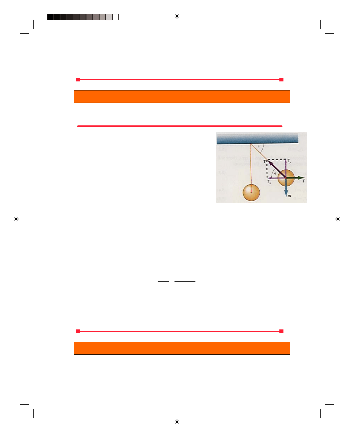
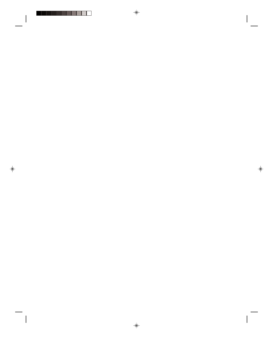
Example 5.2
The ball is pulled to one side. A ball hanging from a rope, is pulled to the right by a horizontal force F such that
the rope makes an angle
θ with the ceiling, as shown in figure 5.4. What is the tension in the rope?
Solution
The first thing that we should observe is that the system is at rest.
Therefore, the ball is in static equilibrium and the first condition of
equilibrium holds. But the tension T is neither in the x- nor y-
direction. Before we can use equations 5.4 and 5.5, we must resolve
the tension T into its components, T
x
and T
y,
as shown in figure 5.4.
The first condition of equilibrium,
Σ F
x
= 0 (5.4)
is applied, which, as we see from figure 5.4 gives
Σ F
x
= F
− T
x
= 0
or
F = T
x
= T cos
θ (5.6)
Figure 5.4
Ball pulled to one side.
Similarly,
Σ F
y
= 0 (5.5)
becomes
Σ F
y
= T
y
− w = 0
T
y
= T sin
θ = w (5.7)
Note that there are four quantities T,
θ, w, and F and only two equations, 5.6 and 5.7. Therefore, if any two of the
four quantities are specified, the other two can be determined. Recall that in order to solve a set of algebraic
equations there must always be the same number of equations as unknowns.
For example, if w = 5.00 N and
θ = 40.0
0
, what is the tension T and the force F. We use equation 5.7 to
solve for the tension:
T = w = 5.00 N = 7.78 N
sin
θ sin 40.0
0
We determine the force F, from equation 5.6, as
F = T cos
θ = 7.78 N cos 40.0
0
= 5.96 N
To go to this Interactive Example click on this sentence.
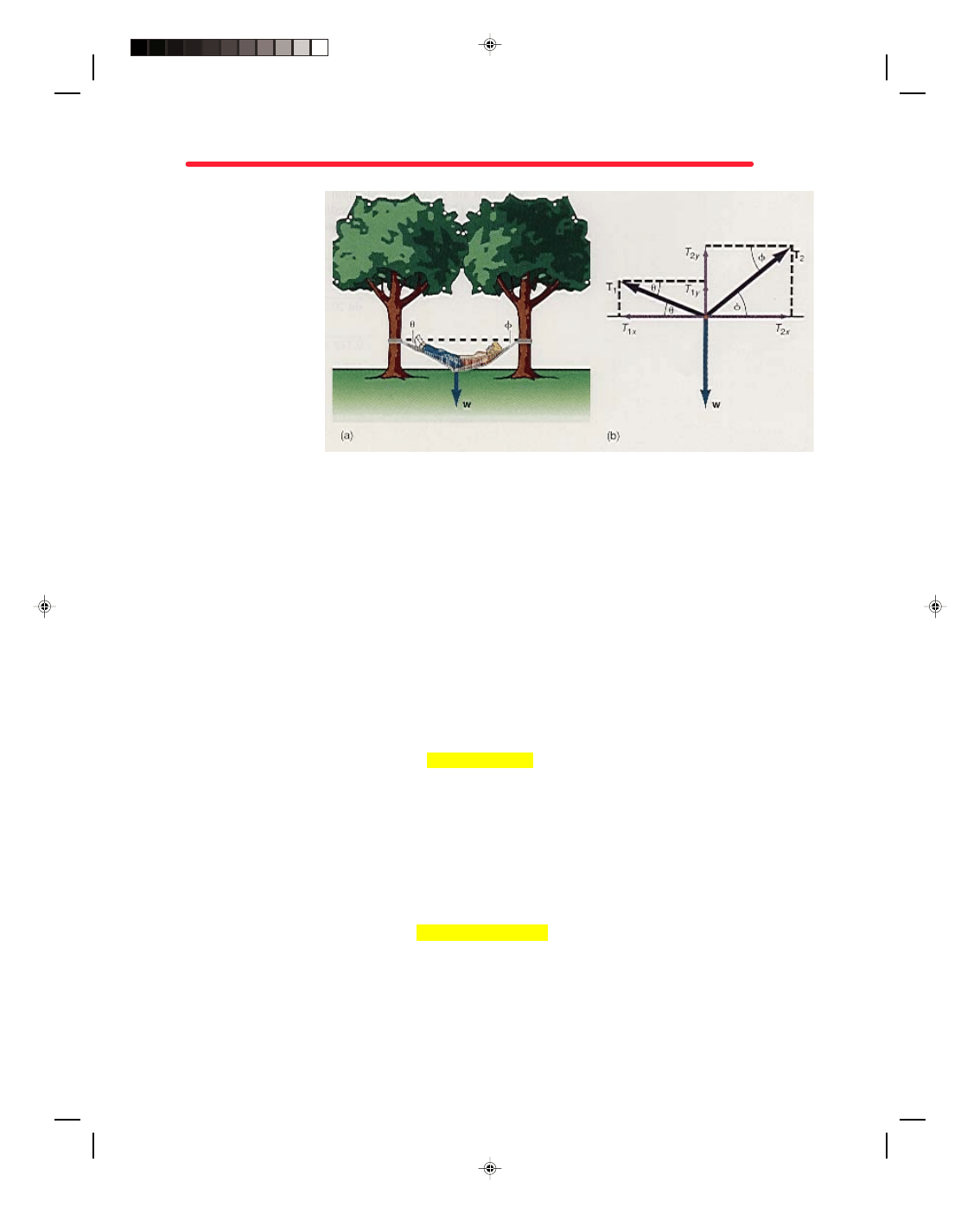
Example 5.3
Resting in your hammock. A 68.0-kg person lies in a hammock, as shown in figure 5.5(a). The rope at the person’s
head makes an angle
φ of 40.0
0
with the horizontal, while the rope at the person’s feet makes an angle
θ of 20.0
0
.
Find the tension in the two ropes.
Pearson Custom Publishing
141
5-4 Mechanics
Solution
Since we will be dealing
with forces it is convenient
for us to express the mass of
the person as a weight
immediately. That is,
w = mg = (68.0 kg)(9.80
m/s
2
) = 666 N
All the forces that are
acting on the hammock are
drawn in figure 5.5(b). The
forces are resolved into
their components, as shown
in figure 5.5(b), where
Figure 5.5
Lying in a hammock.
1
1
1
1
2
2
2
2
cos
sin
cos
sin
x
y
x
y
T
T
T
T
T
T
T
T
θ
θ
φ
φ
=
=
=
=
(5.8)
The first thing we observe is that the hammock is at rest under the influence of several forces and is therefore in
static equilibrium. Thus, the first condition of equilibrium must hold. Setting the forces in the x-direction to zero,
equation 5.4,
Σ F
x
= 0
gives
Σ F
x
= T
2x
− T
1x
= 0
and
T
2x
= T
1x
Using equations 5.8 for the components, this becomes
T
2
cos
φ = T
1
cos
θ (5.9)
Taking all the forces in the y-direction and setting them equal to zero,
Σ F
y
= 0 (5.5)
gives
Σ F
y
= T
1y
+ T
2y
− w = 0
and
T
1y
+ T
2y
= w
Using equations 5.8 for the components, this becomes
T
1
sin
θ + T
2
sin
φ = w (5.10)
Equations 5.9 and 5.10 represent the first condition of equilibrium as it applies to this problem. Note that there
are five quantities, T
1
, T
2
, w,
θ, and φ and only two equations. Therefore, three of these quantities must be
specified in order to solve the problem. In this case,
θ, φ, and w are given and we will determine the tensions T
1
and T
2
.
Let us start by solving equation 5.9 for T
2
, thus,
Pearson Custom Publishing
142
Chapter 5 Equilibrium 5-5
T
2
= T
1
cos
θ (5.11)
cos
φ
We cannot use equation 5.11 to solve for T
2
at this point, because T
1
is unknown. Equation 5.11 says that if T
1
is
known, then T
2
can be determined. If we substitute this equation for T
2
into equation 5.10, thereby eliminating T
2
from the equations, we can solve for T
1
. That is, equation 5.10 becomes
1
1
cos
sin
sin
cos
T
T
w
θ
θ
φ
φ
+
=
Factoring out T
1
we get
1
cos sin
sin
cos
T
w
θ
φ
θ
φ
+
=
(5.12)
Finally, solving equation 5.12 for the tension T
1
, we obtain
T
1
= w (5.13)
sin
θ + cos θ tan φ
Note that sin
φ/cosφ in equation 5.12 was replaced by tanφ, its equivalent, in equation 5.13. Substituting the values
of w = 668 N,
θ = 20.0
0
, and
φ = 40.0
0
into equation 5.13, we find the tension T
1
as
T
1
= w (5.13)
sin
θ + cos θ tan φ
= 666 N
sin 20.0
0
+ cos 20.0
0
tan 40.0
0
= 666 N = 666 N
0.342 + 0.940(0.839) 1.13
= 589 N
Substituting this value of T
1
into equation 5.11, the tension T
2
in the second rope becomes
T
2
= T
1
cos
θ = 589 N cos 20.0
0
cos
φ cos 40.0
0
= 723 N
Note that the tension in each rope is different, that is, T
1
is not equal to T
2
. The ropes that are used for this
hammock must be capable of withstanding these tensions or they will break.
An interesting special case arises when the angles
θ and φ are equal. For this case equation 5.11 becomes
T
2
= T
1
cos
θ = T
1
cos
θ = T
1
cos
φ cos θ
that is,
T
2
= T
1
For this case, T
1
, found from equation 5.13, is
T
1
= w
sin
θ + cos θ (sin θ/cos θ)
= w (5.14)
2 sin
θ
Thus, when the angle
θ is equal to the angle φ, the tension in each rope is the same and is given by equation 5.14.
Note that if
θ were equal to zero in equation 5.14, the tension in the ropes would become infinite. Since this is
impossible, the rope must always sag by some amount.
To go to this Interactive Example click on this sentence.
Pearson Custom Publishing
143
5-6 Mechanics
Before leaving this section on the equilibrium of a body let us reiterate that although the problems
considered here have been problems where the body is at rest under the action of forces, bodies moving at constant
velocity are also in equilibrium. Some of these problems have already been dealt with in chapter 4, that is,
examples 4.11 and 4.14 when a block was moving at a constant velocity under the action of several forces, it was a
body in equilibrium.
5.2 The Concept of Torque
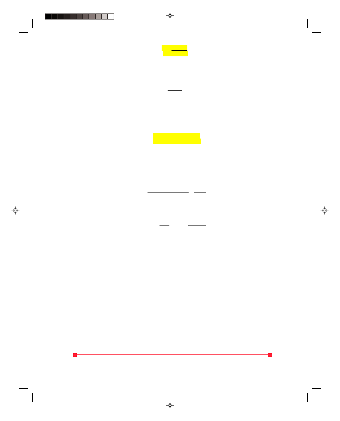
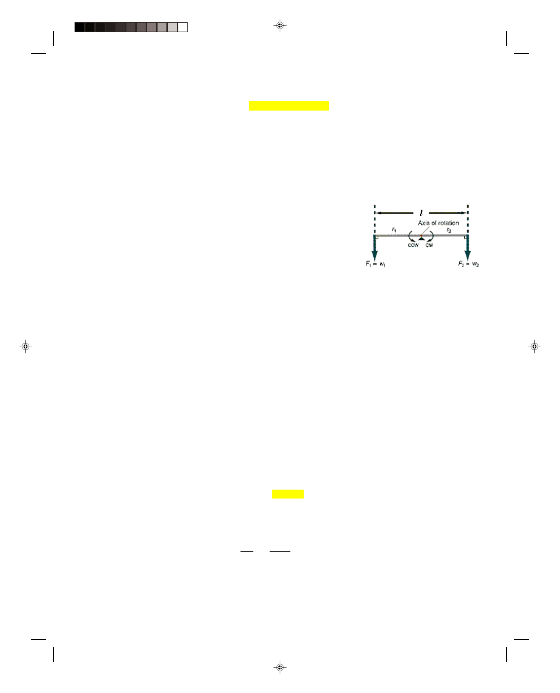
Let us now consider the familiar seesaw you played on in the local school yard during your childhood. Suppose a
30.6-kg child (m
1
) is placed on the left side of a weightless seesaw and another 20.4-kg child (m
2
) is placed on the
right side, as shown in figure 5.6. The weights of the two children
(a) (b)
Figure 5.6
The seesaw.
w
1
= m
1
g = (30.6 kg)(9.80 m/s
2
) = 300 N
w
2
= m
2
g = (20.4 kg)(9.80 m/s
2
) = 200 N
exert forces down on the seesaw, while the support in the middle exerts a force upward, which is exactly equal to
the weight of the two children. According to the first condition of equilibrium,
Σ F
y
= 0
the body should be in equilibrium. However, we know from experience that if a 300-N child is at the left end, and a
200-N child is at the right end, the 300-N child will move downward, while the 200-N child moves upward. That is,
the seesaw rotates in a counterclockwise direction. Even though the first condition of equilibrium holds, the body
is not in complete equilibrium because the seesaw has tilted. It is obvious that the first condition of equilibrium is
not sufficient to describe equilibrium. The first condition takes care of the problem of translational equilibrium
(i.e., the body will not accelerate either in the x-direction or the y-direction), but it says nothing about the problem
of rotational equilibrium.
In fact, up to this point in almost all our discussions we assumed that all the forces that act on a body all
pass through the center of the body. With the seesaw, the forces do not all pass through the center of the body
(figure 5.6), but rather act at different locations on the body. Forces acting on a body that do not all pass through
one point of the body are called nonconcurrent forces. Hence, even though the forces acting on the body cause the
body to be in translational equilibrium, the body is still capable of rotating. Therefore, we need to look into the
problem of forces acting on a body at a point other than the center of the body; to determine how these off-center
forces cause the rotation of the body; and finally to prevent this rotation so that the body will also be in rotational
equilibrium. To do this, we need to introduce the concept of torque.
Torque is defined to be the product of the force times the lever arm. The lever arm is defined as the
perpendicular distance from the axis of rotation to the line along which the force acts. The line along which the
force acts is in the direction of the force vector F, and it is sometimes called the line of action of the force. The line
of action of a force passes through the point of application of the force and is parallel to F. This is best seen in
figure 5.7. The lever arm appears as r
⊥
, and the force is denoted by F. Note that r
⊥
is perpendicular to F.
The magnitude of the torque
τ (the Greek letter tau) is then defined mathematically as
Pearson Custom Publishing
144
Chapter 5 Equilibrium 5-7
τ = r
⊥
F (5.15)
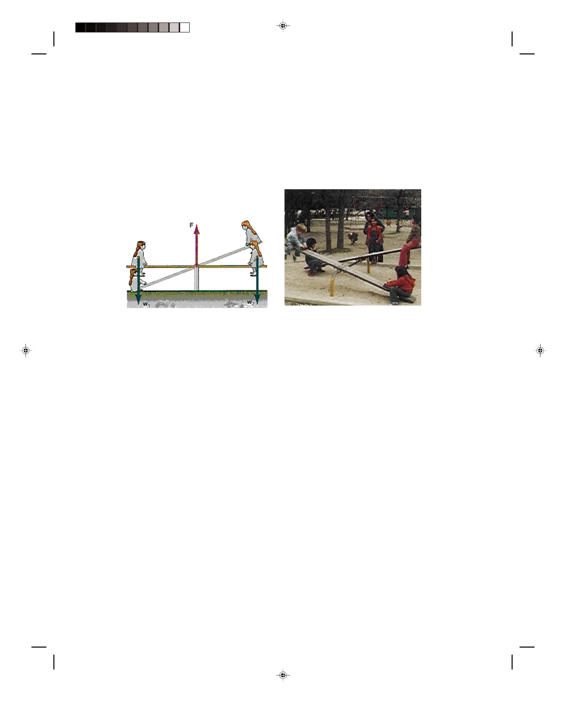
What does this mean physically? Let us consider a very simple example of a torque
acting on a body. Let the body be the door to the room. The axes of rotation of the
door pass through those hinges that you see at the edge of the door. The distance
from the hinge to the door knob is the lever arm r
⊥
, as shown in figure 5.8. If we
exert a force on the door knob by pulling outward, perpendicular to the door, then
we have created a torque that acts on the door and is given by equation 5.15. What
happens to the door? It opens, just as we would expect. We have caused a
Figure 5.7
Torque defined.
rotational motion of the door
by applying a torque.
Therefore, an unbalanced
torque acting on a body at rest
causes that body to be put into
rotational motion. Torque
comes from the Latin word
torquere, which means to
twist. We will see in chapter
9, on rotational motion, that
torque is the rotational
analogue of force. When an
unbalanced force acts on a
body, it gives that body a
translational acceleration.
When an unbalanced torque
acts on a body, it gives that
body a rotational acceleration.
It is not so much the
applied force that opens a
door, but rather the applied
torque; the product of the
force that we apply and the
Figure 5.8
An example of a torque applied to a door.
lever arm. A door knob is therefore placed as far away from the hinges as possible to give the maximum lever arm
and hence the maximum torque for a given force.
Because the torque is the product of r
⊥
and the force F, for a given value of the force, if the distance r
⊥
is
cut in half, the value of the torque will also be cut in half. If the
torque is to remain the same when the lever arm is halved, the
force must be doubled, as we easily see in equation 5.15. If a door
knob was placed at the center of the door, then twice the original
force would be necessary to give the door the same torque. It may
even seem strange that some manufacturers of cabinets and
furniture place door knobs in the center of cabinet doors because
they may have a certain aesthetic value when placed there, but
they cause greater exertion by the furniture owner in order to
open those doors.
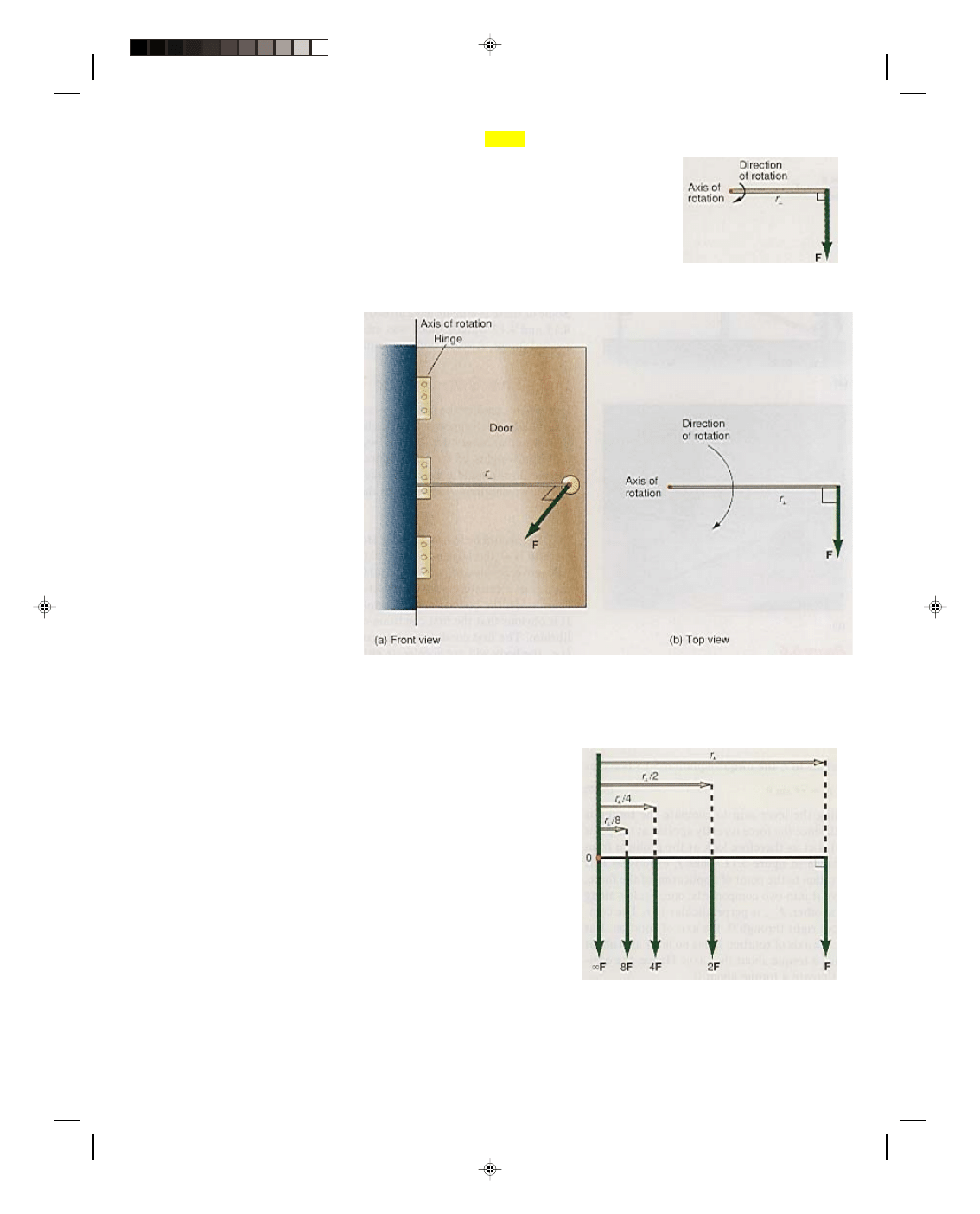
If the door knob was moved to a quarter of the original
distance, then four times the original force would have to be
exerted in order to supply the necessary torque to open the door.
We can see this effect in the diagram of figure 5.9. If the lever arm
was finally decreased to zero, then it would take an infinite force
to open the door, which is of course impossible. In general, if a
Figure 5.9
If the lever arm decreases, the force
must be increased to give the same torque.
Pearson Custom Publishing
145
5-8 Mechanics
force acts through the axis of rotation of a body, it has no lever arm (i.e., r
⊥
= 0) and therefore cannot cause a torque
to act on the body about that particular axis, that is, from equation 5.15
τ = r
⊥
F = (0)F = 0
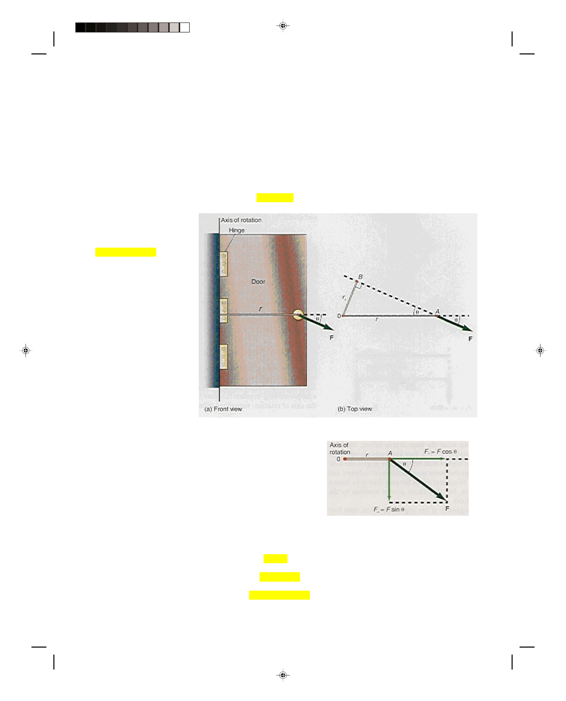
Instead of exerting a force perpendicular to the door, suppose we exert a force at some other angle
θ, as
shown in figure 5.10(a), where
θ is the angle between the extension of r and the direction of F. Note that in this
case r is not a lever arm since it is not perpendicular to F. The definition of a lever arm is the perpendicular
distance from the axis of rotation to the line of action of the force. To obtain the lever arm, we extend a line in
either the forward or backward direction of the force. Then we drop a perpendicular to this line, as shown in figure
5.10(b). The line extended in the direction of the force vector, and through the point of application of the force, is
the line of action of the force. The lever arm, obtained from the figure, is
r
⊥
= r sin
θ (5.16)
In general, if the force is not
perpendicular to r, the torque
equation 5.15 becomes
τ = r
⊥
F = rF sin
θ (5.17)
Although this approach to using
the lever arm to compute the
torque is correct, it may seem
somewhat artificial, since the
force is really applied at the
point A and not the point B in
figure 5.10(b). Let us therefore
look at the problem from a
slightly different point of view,
as shown in figure 5.11. Take r,
exactly as it is given—the
distance from the axis of
rotation to the point of
application of the force. Then
take the force vector F and
resolve it into two components:
one, F
||
, lies along the direction
Figure 5.10
If the force is not perpendicular to r.
of r (parallel to r), and the other, F
⊥
, is perpendicular to r. The
component F
||
is a force component that goes right through 0, the
axis of rotation. But as just shown, if the force goes through the axis
of rotation it has no lever arm about that axis and therefore it
cannot produce a torque about that axis. Hence, the component of
the force parallel to r cannot create a torque about 0.
The component F
⊥
, on the other hand, does produce a
torque, because it is an application of a force that is perpendicular
to a distance r. This perpendicular component produces a torque
given by
Figure 5.11
The parallel and perpendicular
components of a force.
τ = rF
⊥
(5.18)
But from figure 5.11 we see that
F
⊥
= F sin
θ (5.19)
Thus, the torque becomes
τ = rF
⊥
= rF sin
θ (5.20)
Pearson Custom Publishing
146
Chapter 5 Equilibrium 5-9
Comparing equation 5.17 to equation 5.20, it is obvious that the results are identical and should be combined into
one equation, namely
τ = r
⊥
F = rF
⊥
= rF sin
θ (5.21)
Therefore, the torque acting on a body can be computed either by (a) the product of the force times the lever
arm, (b) the product of the perpendicular component of the force times the distance r, or (c) simply the product of r
and F times the sine of the angle between F and the extension of r.
The unit of torque is given by the product of a distance times a force and in SI units, is a m N, (meter
newton).
5.3 The Second Condition of Equilibrium
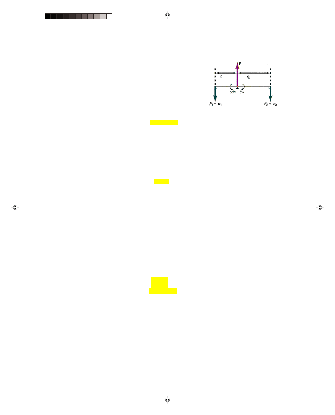
Let us now return to the problem of the two children on the seesaw in
figure 5.6, which is redrawn schematically in figure 5.12. The entire length
l of the seesaw is 4.00 m. From the discussion of torques, it is now obvious
that each child produces a torque tending to rotate the seesaw plank. The
first child produces a torque about the axis of rotation, sometimes called
the fulcrum, given by
τ
1
= F
1
r
1
= w
1
r
1
= (300 N)(2.00 m)
= 600 m N
Figure 5.12
The seesaw revisited.
which has a tendency to rotate the seesaw counterclockwise (ccw). A torque that produces a counterclockwise
rotation is sometimes called a counterclockwise torque. The second child produces a torque about the fulcrum given
by
τ
2
= F
2
r
2
= w
2
r
2
= (200 N)(2.00 m)
= 400 m N
which has a tendency to rotate the seesaw clockwise (cw). A torque that produces a clockwise rotation is sometimes
called a clockwise torque. These tendencies to rotate the seesaw are opposed to each other. That is,
τ
1
tends to
produce a counterclockwise rotation with a magnitude of 600 m N, while
τ
2
has the tendency to produce a
clockwise rotation with a magnitude of 400 m N. It is a longstanding convention among physicists to designate
counterclockwise torques as positive, and clockwise torques as negative. This conforms to the mathematicians’
practice of plotting positive angles on an xy plane as measured counterclockwise from the positive x-axis. Hence,
τ
1
is a positive torque and
τ
2
is a negative torque and the net torque will be the difference between the two, namely
net
τ = τ
1
− τ
2
= 600 m N
− 400 m N = 200 m N
or a net torque
τ of 200 m N, which will rotate the seesaw counterclockwise.
It is now clear why the seesaw moved. Even though the forces acting on it were balanced, the torques were
not. If the torques were balanced then there would be no tendency for the body to rotate, and the seesaw would also
be in rotational equilibrium. That is, the necessary condition for the body to be in rotational equilibrium is that the
torques clockwise must be equal to the torques counterclockwise. That is,
τ
cw
=
τ
ccw
(5.22)
For this case
w
1
r
1
= w
2
r
2
(5.23)
We can now solve equation 5.23 for the position r
1
of the first child such that the torques are equal. That is,
r
1
= w
2
r
2
= 200 N(2.00 m) = 1.33 m
w
1
300 N
If the 300-N child moves in toward the axis of rotation by 0.67 m (2.00
− 1.33 m from axis), then the torque
counterclockwise becomes
Pearson Custom Publishing
147
5-10 Mechanics
τ
1
=
τ
ccw
= w
1
r
1
= (300 N)(1.33 m) = 400 m N
which is now equal to the torque
τ
2
clockwise. Thus, the torque tending to
rotate the seesaw counterclockwise (400 m N) is equal to the torque
tending to rotate it clockwise (400 m N). Hence, the net torque is zero and
the seesaw will not rotate. The seesaw is now said to be in rotational
equilibrium. This equilibrium condition is shown in figure 5.13.
In general, for any rigid body acted on by any number of planar
torques, the condition for that body to be in rotational equilibrium is that
the sum of all the torques clockwise must be equal to the sum of all the
torques counterclockwise. Stated mathematically, this becomes
Figure 5.13
The seesaw in equilibrium.
Σ τ
cw
=
Σ τ
ccw
(5.24)
This condition is called the second condition of equilibrium.
If we subtract the term
Σ τ
cw
from both sides of the equation, we obtain
Σ τ
ccw
− Σ τ
cw
= 0
But the net torque is this difference between the counterclockwise and clockwise torques, so that the second
condition for equilibrium can also be written as: for a rigid body acted on by any number of torques, the condition
for that body to be in rotational equilibrium is that the sum of all the torques acting on that body must be zero, that
is,
Σ τ = 0 (5.25)
The torque is about an axis that is perpendicular to the plane of the paper. Since the plane of the paper is the x,y
plane, the torque axis lies along the z-axis. Hence the torque can be represented as a vector that lies along the z-
axis. Thus, we can also write equation 5.25 as
Σ τ
z
= 0
In general torques can also be exerted about the x-axis and the y-axis, and for such general cases we have
Σ τ
x
= 0
Σ τ
y
= 0
However, in this text we will restrict ourselves to forces in the x,y plane and torques along the z-axis.
5.4 Equilibrium of a Rigid Body
In general, for a body that is acted on by any number of planar forces, the conditions for that body to be in
equilibrium are
Σ F
x
= 0 (5.4)
Σ F
y
= 0 (5.5)
Σ τ
cw
=
Σ τ
ccw
(5.24)
The first condition of equilibrium guarantees that the body will be in translational equilibrium, while the
second condition guarantees that the body will be in rotational equilibrium. The solution of various problems of
statics reduce to solving the three equations 5.4, 5.5, and 5.25. Section 5.5 is devoted to the solution of various
problems of rigid bodies in equilibrium.
5.5 Examples of Rigid Bodies in Equilibrium
Parallel Forces
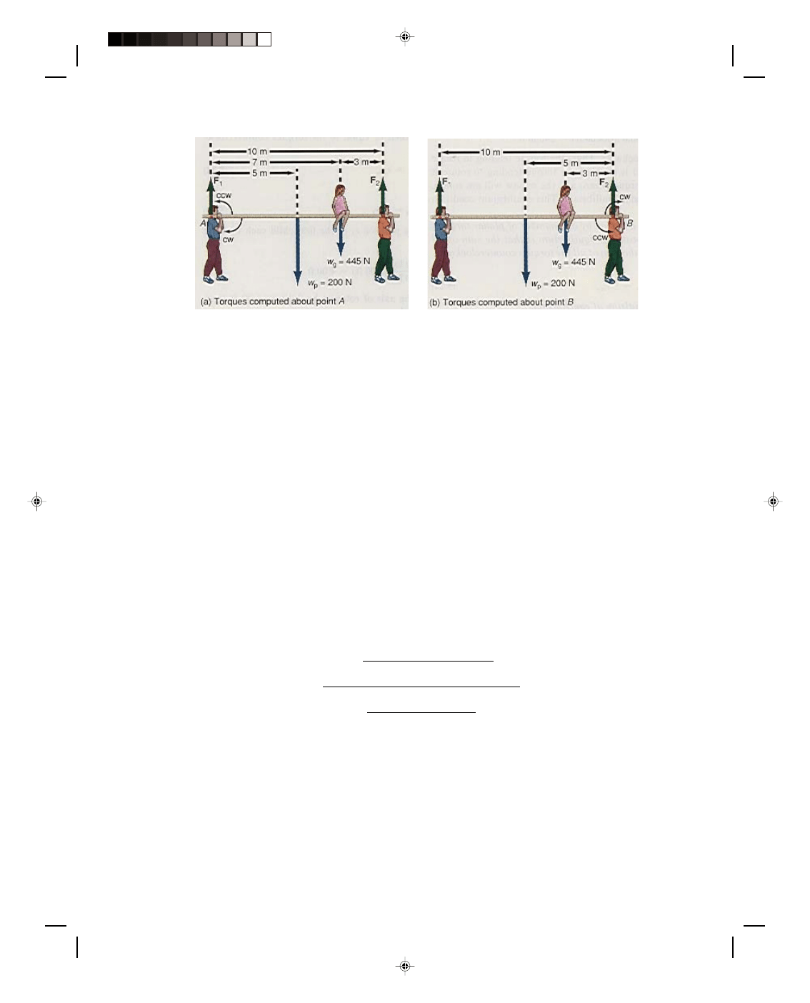
Two men are carrying a girl on a large plank that is 10.000 m long and weighs 200.0 N. If the girl weighs 445.0 N
and sits 3.000 m from one end, how much weight must each man support?
Pearson Custom Publishing
148
Chapter 5 Equilibrium 5-11
The diagram drawn in figure 5.14(a) shows all the forces that are acting on the plank. We assume that the
plank is uniform and the weight of the plank can be located at its center.
Figure 5.14
A plank in equilibrium under parallel forces.
The first thing we note is that the body is in equilibrium and therefore the two conditions of equilibrium
must hold. The first condition of equilibrium, equation 5.5, applied to figure 5.14 yields,
Σ F
y
= 0
F
1
+ F
2
− w
p
− w
g
= 0
F
1
+ F
2
= w
p
+ w
g
= 200.0 N + 445.0 N
F
1
+ F
2
= 645.0 N (5.26)
Since there are no forces in the x-direction, we do not use equation 5.4. The second condition of equilibrium, given
by equation 5.24, is
Σ τ
cw
=
Σ τ
ccw
However, before we can compute any torques, we must specify the axis about which the torques will be computed.
(In a moment we will see that it does not matter what axis is taken.) For now, let us consider that the axis passes
through the point A, where man 1 is holding the plank up with the force F
1
. The torques tending to rotate the
plank clockwise about axis A are caused by the weight of the plank and the weight of the girl, while the torque
tending to rotate the plank counterclockwise about the same axis A is produced by the force F
2
of the second man.
Therefore,
Σ τ
cw
=
Σ τ
ccw
w
p
(5.000 m) + w
g
(7.000 m) = F
2
(10.000 m)
Solving for the force F
2
exerted by the second man,
F
2
= w
p
(5.000 m) + w
g
(7.000 m)
10.000 m
= (200.0 N)(5.000 m) + (445.0 N)(7.000 m)
10.000 m
= 1000 m N + 3115 m N
10.000 m
F
2
= 411.5 N (5.27)
Thus, the second man must exert a force upward of 411.5 N. The force that the first man must support, found from
equations 5.26 and 5.27, is
F
1
+ F
2
= 645.0 N
F
1
= 645 N
− F
2
= 645.0 N
− 411.5 N
F
1
= 233.5 N
Pearson Custom Publishing
149
5-12 Mechanics
The first man must exert an upward force of 233.5 N while the second man carries the greater burden of 411.5 N.
Note that the force exerted by each man is different. If the girl sat at the center of the plank, then each man would
exert the same force.
Let us now see that the same results occur if the torques are computed about any other axis. Let us
arbitrarily take the position of the axis to pass through the point B, the location of the force F
2
. Since F
2
passes
through the axis at point B it cannot produce any torque about that axis because it now has no lever arm. The
force F
1
now produces a clockwise torque about the axis through B, while the forces w
p
and w
g
produce a
counterclockwise torque about the axis through B. The solution is
Σ F
y
= 0
F
1
+ F
2
− w
p
− w
g
= 0
F
1
+ F
2
= w
p
+ w
g
= 645.0 N
and
Σ τ
cw
=
Σ τ
ccw
F
1
(10.000 m) = w
p
(5.000 m) + w
g
(3.000 m)
Solving for the force F
1
,
F
1
= (200.0 N)(5.000 m) + (445.0 N)(3.000 m)
10.000 m
= 1000 m N + 1335 m N
10.000 m
= 233.5 N
while the force F
2
is
F
2
= 645.0 N
− F
1
= 645.0 N
− 233.5 N
= 411.5 N
Notice that F
1
and F
2
have the same values as before. As an exercise, take the center of the plank as the point
through which the axis passes. Compute the torques about this axis and show that the results are the same.
In general, whenever a rigid body is in equilibrium, every point of that body is in both translational
equilibrium and rotational equilibrium, so any point of that body can serve as an axis to compute torques. Even a
point outside the body can be used as an axis to compute torques if the body is in equilibrium.
As a general rule, in picking an axis for the computation of torques, try to pick the point that has the
largest number of forces acting through it. These forces have no lever arm, and hence produce a zero torque about
that axis. This makes the algebra of the problem easier to handle.
The Center of Gravity of a Body
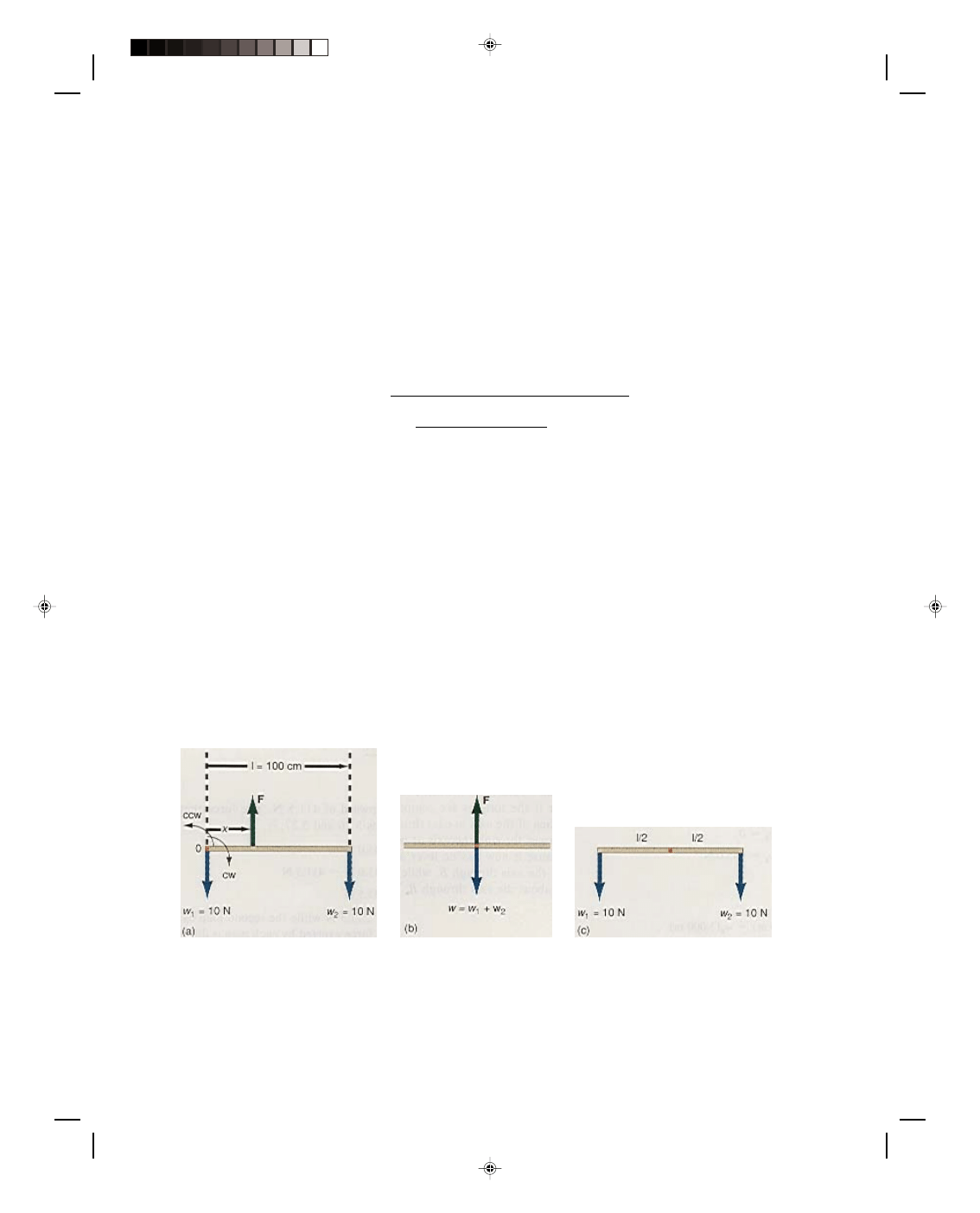
A meter stick of negligible weight has a 10.0-N weight hung from each end. Where, and with what force, should
the meter stick be picked up such that it remains horizontal while it moves upward at a constant velocity? This
problem is illustrated in figure 5.15.
Figure 5.15
The center of gravity of a meter stick.
The meter stick and the two weights constitute a system. If the stick translates with a constant velocity,
then the system is in equilibrium under the action of all the forces. The conditions of equilibrium must apply and
hence the sum of the forces in the y-direction must equal zero,
Σ F
y
= 0 (5.5)
Pearson Custom Publishing
150
Chapter 5 Equilibrium 5-13
Applying equation 5.5 to this problem gives
F
− w
1
− w
2
= 0
F = w
1
+ w
2
= 10.0 N + 10.0 N = 20.0 N
Therefore, a force of 20 N must be exerted in order to lift the stick. But where should this force be applied? In
general, the exact position is unknown so we assume that it can be lifted at some point that is a distance x from
the left end of the stick. If this is the correct position, then the body is also in rotational equilibrium and the
second condition of equilibrium must also apply. Hence, the sum of the torques clockwise must be set equal to the
sum of the torques counterclockwise,
Σ τ
cw
=
Σ τ
ccw
(5.24)
Taking the left end of the meter stick as the axis of rotation, the second condition, equation 5.24, becomes
w
2
l = Fx (5.28)
Since we already found F from the first condition, and w
2
and l are known, we can solve for x, the point where the
stick should be lifted:
x = w
2
l = (10.0 N)(100 cm)
F 20.0 N
= 50.0 cm
The meter stick should be lifted at its exact geometrical center.
The net effect of these forces can be seen in figure 5.15(b). The force up F is equal to the weight down W.
The torque clockwise is balanced by the counterclockwise torque, and there is no tendency for rotation. The stick,
with its equal weights at both ends, acts as though all the weights were concentrated at the geometrical center of
the stick. This point that behaves as if all the weight of the body acts through it, is called the center of gravity
(cg) of the body. Hence the center of gravity of the system, in this case a meter stick and two equal weights
hanging at the ends, is located at the geometrical center of the meter stick.
The center of gravity is located at the center of the stick because of the symmetry of the problem. The
torque clockwise about the center of the stick is w
2
times l/2, while the torque counterclockwise about the center of
the stick is w
1
times l/2, as seen in figure 5.15(c). Because the weights w
1
and w
2
are equal, and the lever arms (l/2)
are equal, the torque clockwise is equal to the torque counterclockwise. Whenever such symmetry between the
weights and the lever arms exists, the center of gravity is always located at the geometric center of the body or
system of bodies.
Example 5.4
The center of gravity when there is no symmetry. If weight w
2
in the preceding discussion is changed to 20.0 N,
where will the center of gravity of the system be located?
Solution
The first condition of equilibrium yields
Σ F
y
= 0
F
− w
1
− w
2
= 0
F = w
1
+ w
2
= 10.0 N + 20.0 N
= 30.0 N
The second condition of equilibrium again yields equation 5.28,
w
2
l = Fx
The location of the center of gravity becomes
x = w
2
l = (20.0 N)(100 cm)
F 30.0 N
= 66.7 cm
Thus, when there is no longer the symmetry between weights and lever arms, the center of gravity is no longer
located at the geometric center of the system.
Pearson Custom Publishing
151
5-14 Mechanics
To go to this Interactive Example click on this sentence.
General Definition of the Center of Gravity
In the previous section we assumed that the weight of the meter stick was negligible compared to the weights w
1
and w
2
. Suppose the weights w
1
and w
2
are eliminated and we want to pick up the meter stick all by itself. The
weight of the meter stick can no longer be ignored. But how can the weight of the meter stick be handled? In the
previous problem w
1
and w
2
were discrete weights. Here, the weight of the meter stick is distributed throughout
the entire length of the stick. How can the center of gravity of a continuous mass distribution be determined
instead of a discrete mass distribution? From the symmetry of the uniform meter stick, we expect that the center
of gravity should be located at the geometric center of the 100-cm meter stick, that is, at the point x = 50 cm. At
this center point, half the mass of the stick is to the left of center, while the other half of the mass is to the right of
center. The half of the mass on the left side creates a torque counterclockwise about the center of the stick, while
the half of the mass on the right side creates a torque clockwise. Thus, the uniform meter stick has the same
symmetry as the stick with two equal weights acting at its ends, and thus must have its center of gravity located
at the geometrical center of the meter stick, the 50-cm mark.
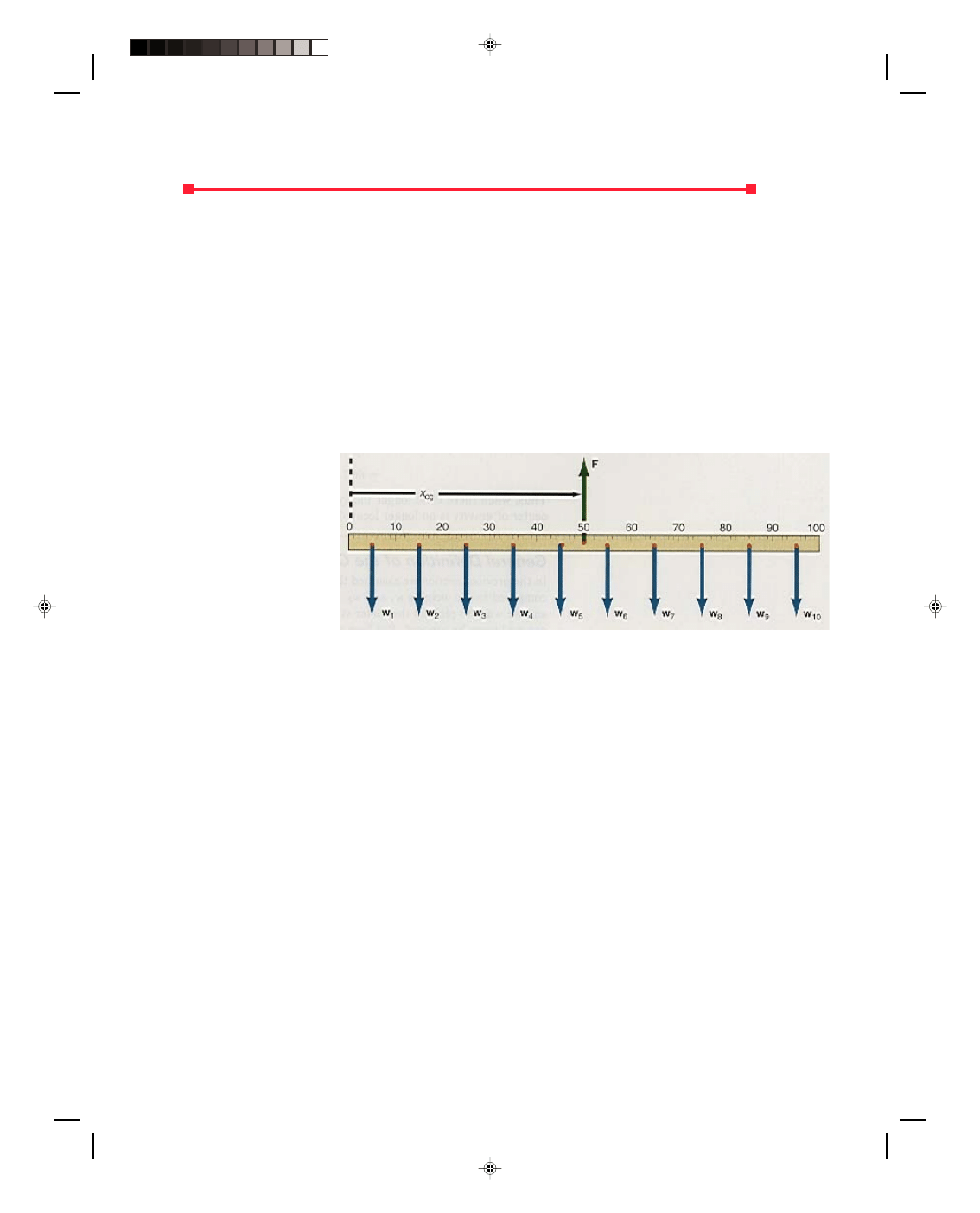
To find a general equation for the center of gravity of a body, let us find the equation for the center of
gravity of the uniform meter
stick shown in figure 5.16.
The meter stick is
divided up into 10 equal parts,
each of length 10 cm. Because
the meter stick is uniform,
each 10-cm portion contains
1/10 of the total weight of the
meter stick, W. Let us call
each small weight w
i,
where
the i is a subscript that
identifies which w is being
considered.
Figure 5.16
The weight distribution of a uniform meter stick.
Because of the symmetry of the uniform mass distribution, each small weight w
i
acts at the center of each
10-cm portion. The center of each ith portion, denoted by x
i,
is shown in the figure. If a force F is exerted upward at
the center of gravity x
cg
, the meter stick should be balanced. If we apply the first condition of equilibrium to the
stick we obtain
Σ F
y
= 0 (5.5)
F
− w
1
− w
2
− w
3
− . . . − w
10
= 0
F = w
1
+ w
2
+ w
3
+ . . . + w
10
A shorthand notation for this sum can be written as
1
2
3
10
1
...
n
i
i
w
w
w
w
w
=
+
+
+ +
+ =
∑
The Greek letter
Σ again means “sum of,” and when placed in front of w
i
it means “the sum of each w
i
.” The
notation i = 1 to n, means that we will sum up some n w
i
’s .In this case, n = 10. Using this notation, the first
condition of equilibrium becomes
1
n
i
i
F
w
W
=
=
=
∑
(5.29)
The sum of all these w
i
’s is equal to the total weight of the meter stick W.
The second condition of equilibrium,
Σ τ
cw
=
Σ τ
ccw
(5.24)
when applied to the meter stick, with the axis taken at the zero of the meter stick, yields
Pearson Custom Publishing
152
Chapter 5 Equilibrium 5-15
(w
1
x
1
+ w
2
x
2
+ w
3
x
3
+ . . . + w
10
x
10
) = Fx
cg
In the shorthand notation this becomes
1
n
i i
cg
i
w x
Fx
=
=
∑
Solving for x
cg
, we have
1
n
i i
i
cg
w x
x
F
=
=
∑
(5.30)
Using equation 5.29, the general expression for the x-coordinate of the center of gravity of a body is given by
1
n
i i
i
cg
w x
x
W
=
=
∑
(5.31)
Applying equation 5.31 to the uniform meter stick we have
x
cg
=
Σ w
i
x
i
= w
1
x
1
+ w
2
x
2
+ . . . + w
10
x
10
W W
but since w
1
= w
2
= w
3
= w
4
= . . . = w
10
= W/10, it can be factored out giving
x
cg
= W/10 (x
1
+ x
2
+ x
3
+ . . . + x
10
)
W
= 1/10 (5 + 15 + 25 + 45 + . . . + 95)
= 500/10
= 50 cm
The center of gravity of the uniform meter stick is located at its geometrical center, just as expected from
symmetry considerations. The assumption that the weight of a body can be located at its geometrical center,
provided that its mass is uniformly distributed, has already been used throughout this book. Now we have seen
that this was a correct assumption.
To find the center of gravity of a two-dimensional body, the x-coordinate of the cg is found from equation
5.31, while the y-coordinate, found in an analogous manner, is
1
n
i i
i
cg
w y
y
W
=
=
∑
(5.32)
For a nonuniform body or one with a nonsymmetrical shape, the problem becomes much more complicated
with the sums in equations 5.31 and 5.32 becoming integrals and will not be treated in this book.
Examples Illustrating the Concept of the Center of Gravity
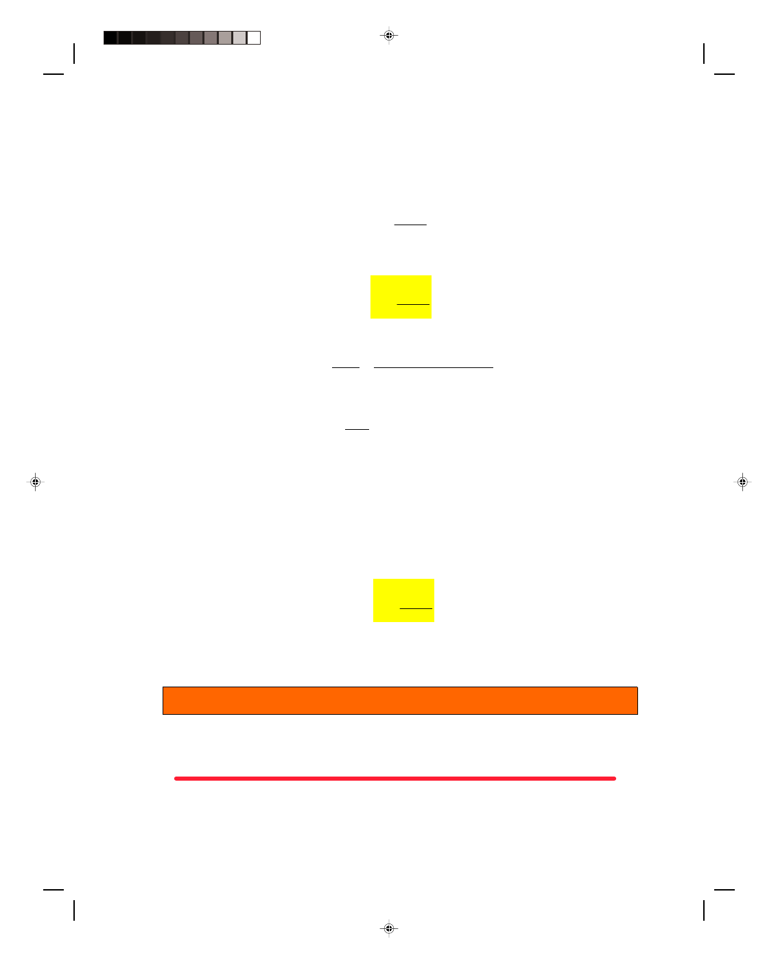
Example 5.5
The center of gravity of a weighted beam. A weight of 50.0 N is hung from one end of a uniform beam 12.0 m long.
If the beam weighs 25.0 N, where and with what force should the beam be picked up so that it remains horizontal?
The problem is illustrated in figure 5.17.
Solution
Because the beam is uniform, the weight of the beam w
B
is located at the geometric center of the beam. Let us
assume that the center of gravity of the system of beam and weight is located at a distance x from the right side of
the beam. The body is in equilibrium, and the equations of equilibrium become
Pearson Custom Publishing
153
5-16 Mechanics
Σ F
y
= 0 (5.5)
F
− w
B
− w
1
= 0
F = w
B
+ w
1
= 25.0 N + 50.0 N = 75.0 N
Taking the right end of the beam as the axis about which the
torques are computed, we have
Σ τ
cw
=
Σ τ
ccw
(5.24)
Figure 5.17
The center of gravity of a
weighted beam.
The force F will cause a torque clockwise about the right end, while the force w
B
will cause a counterclockwise
torque. Hence,
Fx = w
B
l
2
Thus, the center of gravity of the system is located at
x
cg
= w
B
l/2
F
= (25.0 N)(6.0 m) = 2.0 m
75.0 N
Therefore, we should pick up the beam 2.0 m from the right hand side with a force of 75.0 N.
To go to this Interactive Example click on this sentence.
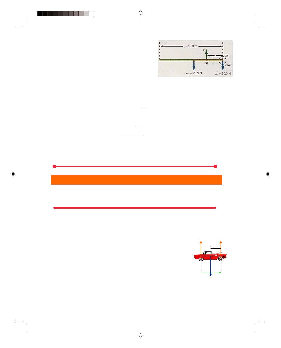
Example 5.6
The center of gravity of an automobile. The front wheels of an automobile, when run onto a platform scale, are
found to support 8010 N, while the rear wheels can support 6680 N. The auto has a 2.00-m. wheel base (distance
from the front axle to the rear axle w
b
). Locate the center of gravity of the car. The car is shown in figure 5.18.
Solution
If the car pushes down on the scales with forces w
1
and w
2
, then the scale exerts normal forces upward of F
N1
and
F
N2
, respectively, on the car. The total weight of the car is W and can be located at the center of gravity of the car.
Since the location of this cg is unknown, let us assume that it is at a distance x from the front wheels. Because the
car is obviously in equilibrium, the conditions of equilibrium are applied. Thus,
Σ F
y
= 0 (5.5)
From figure 5.18, we see that this is
F
N1
+ F
N2
− W = 0
F
N1
+ F
N2
= W
Solving for W, the weight of the car, we get
W = 8010 N + 6680 N = 14,700 N
The second condition of equilibrium, using the front axle of the car as the
axis, gives
Figure 5.18
The center of
gravity of an automobile.
Σ τ
cw
=
Σ τ
ccw
(5.24)
w
x
cg
F
N1
F
N2
w
b
cw
Pearson Custom Publishing
154
Chapter 5 Equilibrium 5-17
The force F
N2
will cause a clockwise torque about the front axle, while W will cause a counterclockwise torque.
Hence,
F
N2
(2.00 m) = Wx
cg
Solving for the center of gravity, we get
x
cg
= F
N2
(2.00 m)
W
= (6680 N)(2.00 m)
14,700 N
= 0.910 m
That is, the cg of the car is located 0.910 m behind the front axle of the car.
To go to this Interactive Example click on this sentence.
Center of Mass
The center of mass (cm) of a body or system of bodies is defined as that point that moves in the same way that a
single particle of the same mass would move when acted on by the same forces. Hence, the point reacts as if all the
mass of the body were concentrated at that point. All the external forces can be considered to act at the center of
mass when the body undergoes any translational acceleration. The general motion of any rigid body can be
resolved into the translational motion of the center of mass and the rotation about the center of mass. On the
surface of the earth, where g, the acceleration due to gravity, is relatively uniform, the center of mass (cm) of the
body will coincide with the center of gravity (cg) of the body. To see this, take equation 5.31 and note that
w
i
= m
i
g
Substituting this into equation 5.31 we get
x
cg
=
Σ w
i
x
i
=
Σ (m
i
g)x
i
Σ w
i
Σ (m
i
g)
Factoring the g outside of the summations, we get
x
cg
= g
Σ m
i
x
i
(5.33)
g
Σ m
i
The right-hand side of equation 5.33 is the defining relation for the center of mass of a body, and we will
write it as
x
cm
=
Σ m
i
x
i
=
Σ m
i
x
i
(5.34)
Σ m
i
M
where M is the total mass of the body. Equation 5.34 represents the x-coordinate of the center of mass of the body.
We obtain a similar equation for the y-coordinate by replacing the letter x with the letter y in equation 5.34:
y
cm
=
Σ m
i
y
i
=
Σ m
i
y
i
(5.35)
Σ m
i
M
Example 5.7
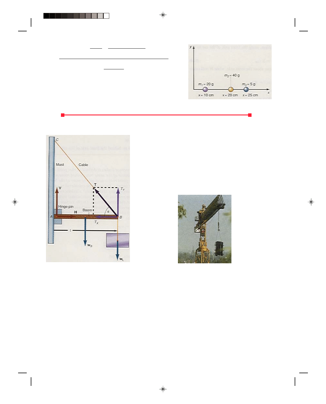
Finding the center of mass. Three masses, m
1
= 20.0 g, m
2
= 40.0 g, and m
3
= 5.00 g are located on the x-axis at
10.0, 20.0, and 25.0 cm, respectively, as shown in figure 5.19. Find the center of mass of the system of three
masses.
Solution
The center of mass is found from equation 5.34 with n = 3. Thus,
Pearson Custom Publishing
155
5-18 Mechanics
x
cm
=
Σ m
i
x
i
= m
1
x
1
+ m
2
x
2
+ m
3
x
3
Σ m
i
m
1
+ m
2
+ m
3
= (20.0 g)(10.0 cm) + (40.0 g)(20.0 cm) + (5.00 g)(25.0 cm)
20.0 g + 40.0 g + 5.00 g
= 1125 g cm
65.0 g
= 17.3 cm
The center of mass of the three masses is at 17.3 cm.
To go to this Interactive Example click on this sentence.
The center of mass.
The Crane Boom
A large uniform boom is connected to the mast by a hinge pin at the
point A in figure 5.20. A load w
L
is to be supported at the other end B.
A cable is also tied to B and connected to the mast at C to give
additional support to the boom. We want to determine all the forces
that are acting on the boom in order to make sure that the boom, hinge
pin, and cable are capable of withstanding these forces when the boom
is carrying the load w
L
.
First, what are the forces acting on the boom? Because the
boom is uniform, its weight w
B
can be situated at its center of gravity,
which coincides with its geometrical center. There is a tension T in the
cable acting at an angle
θ to the boom. At the hinge pin, there are two
forces acting. The first, denoted by V, is a vertical force acting on
(a) (b)
Figure 5.20
The crane boom.
the end of the boom. If this force were not acting on the boom at this end point, this end of the boom would fall
down. That is, the pin with this associated force V is holding the boom up.
Second, there is also a horizontal force H acting on the boom toward the right. The horizontal component of
the tension T pushes the boom into the mast. The force H is the reaction force that the mast exerts on the boom. If
there were no force H, the boom would go right through the mast. The vector sum of these two forces, V and H, is
sometimes written as a single contact force at the location of the hinge pin. However, since we want to have the
forces in the x- and y-directions, we will leave the forces in the vertical and horizontal directions. The tension T in
the cable also has a vertical component T
y,
which helps to hold up the load and the boom.
Let us now determine the forces V, H, and T acting on the system when
θ = 30.0
0
, w
B
= 270 N, w
L
= 900 N,
and the length of the boom, l = 6.00 m. The first thing to do to solve this problem is to observe that the body, the
boom, is at rest under the action of several different forces, and must therefore be in equilibrium. Hence, the first
and second conditions of equilibrium must apply:
Σ F
y
= 0 (5.5)
Pearson Custom Publishing
156

Chapter 5 Equilibrium 5-19
Σ F
x
= 0 (5.4)
Σ τ
cw
=
Σ τ
ccw
(5.24)
Using figure 5.20, we observe which forces are acting in the y-direction. Equation 5.5 becomes
Σ F
y
= V + T
y
− w
B
− w
L
= 0
or
V + T
y
= w
B
+ w
L
(5.36)
Note from figure 5.20 that T
y
= T sin
θ. The right-hand side of equation 5.36 is known, because w
B
and w
L
are
known. But the left-hand side contains the two unknowns, V and T, so we can not proceed any further with this
equation at this time.
Let us now consider the second of the equilibrium equations, namely equation 5.4. Using figure 5.20, notice
that the force in the positive x-direction is H, while the force in the negative x-direction is T
x.
Thus, the
equilibrium equation 5.4 becomes
Σ F
x
= H
− T
x
= 0
or
H = T
x
= T cos
θ (5.37)
There are two unknowns in this equation, namely H and T. At this point, we have two equations with the three
unknowns V, H, and T. We need another equation to determine the solution of the problem. This equation comes
from the second condition of equilibrium, equation 5.24. In order to compute the torques, we must first pick an axis
of rotation. Remember, any point can be picked for the axis to pass through. For convenience we pick the point A
in figure 5.20, where the forces V and H are acting, for the axis of rotation to pass through. The forces w
B
and w
L
are the forces that produce the clockwise torques about the axis at A, while T
y
produces the counterclockwise
torque. Therefore, equation 5.24 becomes
w
B
(l/2) + w
L
(l) = T
y
(l) = T sin
θ (l) (5.38)
After dividing term by term by the length l, we can solve equation 5.38 for T. Thus,
T sin
θ = (w
B
/2) + w
L
The tension in the cable is therefore
T = (w
B
/2) + w
L
(5.39)
sin
θ
Substituting the values of w
B,
w
L
, and
θ, into equation 5.39 we get
T = (270 N/2) + 900 N
sin 30.0
0
or
T = 2070 N
The tension in the cable is 2070 N. We can find the second unknown force H by substituting this value of T into
equation 5.37:
H = T cos
θ = (2070 N)cos 30.0
0
and
H = 1790 N
The horizontal force exerted on the boom by the hinge pin is 1790 N. We find the final unknown force V by
substituting T into equation 5.36, and solving for V, we get
V = w
B
+ w
L
− T sin θ (5.40)
= 270 N + 900 N
− (2070 N)sin 30.0
0
= 135 N
The hinge pin exerts a force of 135 N on the boom in the vertical direction. To summarize, the forces acting on the
boom are V = 135 N, H = 1790 N, and T = 2070 N. The reason we are concerned with the value of these forces, is
Pearson Custom Publishing
157
5-20 Mechanics
that the boom is designed to carry a particular load. If the boom system is not capable of withstanding these forces
the boom will collapse. For example, we just found the tension in the cable to be 2070 N. Is the cable that will be
used in the system capable of withstanding a tension of 2070 N? If it is not, the cable will break, the boom will
collapse, and the load will fall down. On the other hand, is the hinge pin capable of taking a vertical stress of 135
N and a horizontal stress of 1790 N? If it is not designed to withstand these forces, the pin will be sheared and
again the entire system will collapse. Also note that this is not a very well designed boom system in that the hinge
pin must be able to withstand only 135 N in the vertical while the horizontal force is 1790 N. In designing a real
system the cable could be moved to a much higher position on the mast thereby increasing the angle
θ, reducing
the component T
x,
and hence decreasing the force component H.
There are many variations of the boom problem. Some have the boom placed at an angle to the horizontal.
Others have the cable at any angle, and connected to almost any position on the boom. But the procedure for the
solution is still the same. The boom is an object in equilibrium and equations 5.4, 5.5, and 5.24 must apply.
Variations on the boom problem presented here are included in the problems at the end of the chapter.
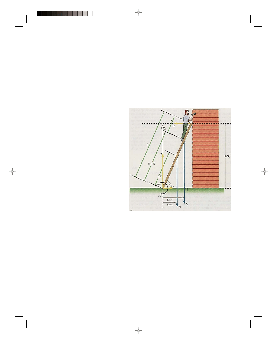
The Ladder
A ladder of length L is placed against a wall, as
shown in figure 5.21. A person, of weight w
P
,
ascends the ladder until the person is located a
distance d from the top of the ladder. We want to
determine all the forces that are acting on the
ladder. We assume that the ladder is uniform.
Hence, the weight of the ladder w
L
can be located
at its geometrical center, that is, at L/2. There are
two forces acting on the bottom of the ladder, V
and H. The vertical force V represents the
reaction force that the ground exerts on the
ladder. That is, since the ladder pushes against
the ground, the ground must exert an equal but
opposite force upward on the ladder.
With the ladder in this tilted position,
there is a tendency for the ladder to slip to the left
at the ground. If there is a tendency for the ladder
to be in motion to the left, then there must be a
frictional force tending to oppose that motion, and
therefore that frictional force must act toward the
right. We call this horizontal frictional force H. At
the top of the ladder there is a force F on the
ladder that acts normal to the wall. This force is
the force that the wall exerts on the ladder and is
the reaction force to the force
Figure 5.21
The ladder.
that the ladder exerts on the wall. There is also a tendency for the ladder to slide down the wall and therefore
there should also be a frictional force on the ladder acting upward at the wall. To solve the general case where
there is friction at the wall is extremely difficult. We simplify the problem by assuming that the wall is smooth
and hence there is no frictional force acting on the top of the ladder. Thus, whatever results that are obtained in
this problem are an approximation to reality.
Since the ladder is at rest under the action of several forces it must be in static equilibrium. Hence, the
first and second conditions of equilibrium must apply. Namely,
Σ F
y
= 0 (5.5)
Σ F
x
= 0 (5.4)
Σ τ
cw
=
Σ τ
ccw
(5.24)
Figure 5.21 shows that the force upward is V, while the forces downward are w
L
and w
p
. Substituting these values
into equation 5.5 gives
Σ F
y
= V
− w
L
− w
p
= 0
or
Pearson Custom Publishing
158
Chapter 5 Equilibrium 5-21
V = w
L
+ w
p
(5.41)
The figure also shows that the force to the right is H, while the force to the left is F. Equation 5.4 therefore
becomes
Σ F
x
= H
− F = 0
or
H = F (5.42)
It is important that you see how equations 5.41 and 5.42 are obtained from figure 5.21. This is the part that really
deals with the physics of the problem. Once all the equations are obtained, their solution is really a matter of
simple mathematics.
Before we can compute any of the torques for the second condition of equilibrium, we must pick an axis of
rotation. As already pointed out, we can pick any axis to compute the torques. We pick the base of the ladder as
the axis of rotation. The forces V and H go through this axis and, therefore, V and H produce no torques about this
axis, because they have no lever arms. Observe from the figure that the weights w
L
and w
p
are the forces that
produce clockwise torques, while F is the force that produces the counterclockwise torque. Recall, that torque is
the product of the force times the lever arm, where the lever arm is the perpendicular distance from the axis of
rotation to the direction or line of action of the force. Note from figure 5.21 that the distance from the axis of
rotation to the center of gravity of the ladder does not make a 90
0
angle with the force w
L
, and therefore L/2 cannot
be a lever arm. If we drop a perpendicular from the axis of rotation to the line showing the direction of the vector
w
L
, we obtain the lever arm (LA) given by
(LA)
1
= (L/2) cos
θ
Thus, the torque clockwise produced by w
L
is
τ
1cw
= w
L
(L/2) cos
θ (5.43)
Similarly, the lever arm associated with the weight of the person is
(LA)
2
= (L
− d) cos θ
Hence, the second torque clockwise is
τ
2cw
= w
p
(L
− d) cos θ (5.44)
The counterclockwise torque is caused by the force F. However, the ladder does not make an angle of 90
0
with the force F, and the length L from the axis of rotation to the wall, is not a lever arm. We obtain the lever arm
associated with the force F by dropping a perpendicular from the axis of rotation to the direction of the force vector
F, as shown in figure 5.21. Note that in order for the force vector to intersect the lever arm, the line from the force
had to be extended until it did intersect the lever arm. We call this extended line the line of action of the force. This
lever arm (LA)
3
is equal to the height on the wall where the ladder touches the wall, and is found by the
trigonometry of the figure as
(LA)
3
= L sin
θ
Hence, the counterclockwise torque produced by F is
τ
ccw
= FL sin
θ (5.45)
Substituting equations 5.43, 5.44, and 5.45 into equation 5.24 for the second condition of equilibrium, yields
w
L
(L/2)cos
θ + w
p
(L
− d)cos θ = FL sin θ (5.46)
The physics of the problem is now complete. It only remains to solve the three equations 5.41, 5.42, and 5.46
mathematically. There are three equations with the three unknowns V, H, and F.
As a typical problem, let us assume that the following data are given:
θ = 60.0
0
, w
L
= 178 N, w
p
= 712 N, L
= 6.10 m, and d = 1.53 m. Equation 5.46, solved for the force F, gives
F = w
L
(L/2)cos
θ + w
p
(L
− d)cos θ (5.47)
L sin
θ
Substituting the values just given, we have
Pearson Custom Publishing
159
5-22 Mechanics
F = 178 N(3.05 m)cos 60.0
0
+ 712 N(4.58 m) cos 60.0
0
6.10 m sin 60.0
0
= 271 m N + 1630 m N
5.28 m
= 360 N
However, since H = F from equation 5.42, we have
H = 360 N
Solving for V from equation 5.41 we obtain
V = w
L
+ w
p
= 178 N + 712 N
= 890 N
Thus, we have found the three forces F, V, and H acting on the ladder.
As a variation of this problem, we might ask, “What is the minimum value of the coefficient of friction
between the ladder and the ground, such that the ladder will not slip out at the ground?” Recall from setting up
this problem, that H is indeed a frictional force, opposing the tendency of the bottom of the ladder to slip out, and
as such is given by
H = f
s
=
µ
s
F
N
(5.48)
But the normal force F
N
that the ground exerts on the ladder, seen from figure 5.21, is the vertical force V. Hence,
H =
µ
s
V
The coefficient of friction between the ground and the ladder is therefore
µ
s
= H
V
For this particular example, the minimum coefficient of friction is
µ
s
= 360 N
890 N
µ
s
= 0.404
If
µ
s
is not equal to, or greater than 0.404, then the necessary frictional force H is absent and the ladder will slide
out at the ground.
Applications of the Theory of Equilibrium to the Health Sciences
Example 5.8
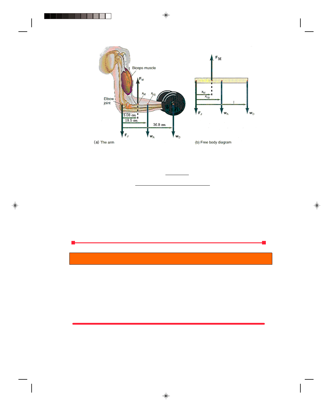
A weight lifter’s dumbbell curls. A weight lifter is lifting a dumbbell that weighs 334 N, as shown in figure 5.22(a)
The biceps muscle exerts a force F
M
upward on the forearm at a point approximately 5.08 cm from the elbow joint.
The forearm weighs approximately 66.8 N and its center of gravity is located approximately 18.5 cm from the
elbow joint. The upper arm exerts a force at the elbow joint that we denote by F
J
. The dumbbell is located
approximately 36.8 cm from the elbow. What force must be exerted by the biceps muscle in order to lift the
dumbbell?
Solution
The free body diagram for the arm is shown in figure 5.22(b). The first condition of equilibrium gives
Σ F
y
= F
M
− F
J
− w
A
− w
D
= 0
F
M
= F
J
+ w
A
+ w
D
(5.49)
F
M
= F
J
+ 66.8 N + 334 N
F
M
= F
J
+ 401 N (5.50)
Taking the elbow joint as the axis, the second condition of equilibrium gives
Σ τ
cw
=
Σ τ
ccw
Pearson Custom Publishing
160
Chapter 5 Equilibrium 5-23
Figure 5.22
The arm lifting a weight.
w
A
x
cg
+ w
D
l = F
m
x
M
(5.51)
The force exerted by the biceps muscle becomes
F
M
= w
A
x
cg
+ w
D
l (5.52)
x
M
= (66.8 N)(0.185 m) + (334 N)(0.368 m)
0.0508 m
= 2660 N
Thus, the biceps muscle exerts the relatively large force of 2660 N in lifting the 334 N dumbbell. We can now find
the force at the joint, from equation 5.50, as
F
J
= F
M
− 401 N
= 2660 N
− 401 N = 2260 N
To go to this Interactive Example click on this sentence.
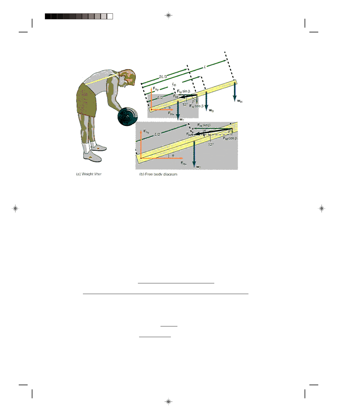
Example 5.9
A weight lifter’s bend over rowing. A weight lifter bends over at an angle of 50.0
0
to the horizontal, as shown in
figure 5.23(a). He holds a barbell that weighs 668 N, w
B
, that is located at L
B
= 50.8 cm. The spina muscle in his
back supplies the force F
M
to hold the spine of his back in this position. The length L of the man’s spine is
approximately 68.6 cm. The spina muscle acts approximately 2L/3 = 45.7 cm from the base of the spine and makes
an angle of 12.0
0
with the spine, as shown. The man’s head weighs about 62.3 N, w
H
, and this force acts at the top
of the spinal column, as shown. The torso of the man weighs about 356 N and this is denoted by w
T
, and is located
at the center of gravity of the torso, which is taken as L/2 = 34.3 cm. At the base of the spinal column is the fifth
lumbar vertebra, which acts as the axis about which the body bends. A reaction force F
R
acts on this fifth lumbar
vertebra, as shown in the figure. Determine the reaction force F
R
and the muscular force F
M
on the spine.
Solution
A free body diagram of all the forces is shown in figure 5.23(b). Note that the angle
β is
β = 90
0
− θ + 12
0
= 90
0
− 50
0
+ 12
0
= 52
0
Pearson Custom Publishing
161
5-24 Mechanics
Figure 5.23
Forces on the spinal column.
The first condition of equilibrium yields
Σ F
y
= 0
F
R
sin
θ − w
T
− w
B
− w
H
− F
M
cos
β = 0
or
F
R
sin
θ = w
T
+ w
B
+ w
H
+ F
M
cos
β (5.53)
and
Σ F
x
= 0
F
R
cos
θ − F
M
sin
β = 0
or
F
R
cos
θ = F
M
sin
β (5.54)
The second condition of equilibrium gives
Σ τ
cw
=
Σ τ
ccw
w
T
(L/2)cos
θ + F
M
cos
β (2L/3)cos θ + w
B
L
B
cos
θ + w
H
L cos
θ = F
M
sin
β (2L/3)sin θ (5.55)
Solving for F
M
, the force exerted by the muscles, gives
F
M
= w
T
(L/2)cos
θ + w
B
L
B
cos
θ + w
H
L cos
θ (5.56)
sin
β (2L/3)sin θ − cos β (2L/3)cos θ
= (356 N)(34.3 cm)(cos 50
0
) + (668 N)(50.8 cm)(cos 50
0
) + (62.3 N)(68.6 cm)(cos 50
0
)
(sin 52
0
)(45.7 cm)(sin 50
0
)
− (cos 52
0
)(45.7 cm)(cos 50
0
)
= 3410 N
The reaction force F
R
on the base of the spine, found from equation 5.54, is
F
R
= F
M
sin
β
cos
θ
= (3410 N)sin 52
0
= 4180 N
cos 50
0
Pearson Custom Publishing
162
Chapter 5 Equilibrium 5-25
Thus in lifting a 668 N barbell there is a force on the spinal disk at the base of the spine of 4180 N
1
. That is, the
force on the spine is 6 times greater than the weight that is lifted.
Have you ever wondered … ?
An Essay on the Application of Physics.
Traction
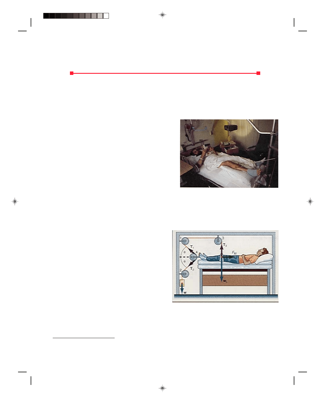
Have you ever wondered, while visiting Uncle Johnny in the
hospital, what they were doing to that poor man in the other
bed (figure 1)? As you can see in figure 2, they have him
connected to all kinds of pulleys, ropes, and weights. It looks
like some kind of medieval torture rack, where they are
stretching the man until he tells all he knows. Or perhaps
the man is a little short for his weight and they are just
trying to stretch him to normal size.
Of course it is none of these things, but the idea of
stretching is correct. Actually the man in the other bed is in
traction. Traction is essentially a process of exerting a force
on a skeletal structure in order to hold a bone in a prescribed
position. Traction is used in the treatment of fractures and is
a direct application of a body in equilibrium under a number
of forces. The object of traction is to exert
Figure 1
A man in traction.
sufficient force to keep the two sections of the fractured bone in alignment and just touching while they heal. The
traction process thus prevents muscle contraction that might cause misalignment at the fracture. The traction
force can be exerted through a splint or by a steel pin passed directly through the bone.
An example of one type of traction, shown in figure 2, is known as Russell traction and is used in the
treatment of a fracture of the femur. Let us analyze the problem from the point of view of equilibrium. First note
that almost all of the forces on the bone are transmitted
by the ropes that pass around the pulleys. The
characteristic of all the systems with pulleys and ropes
that are used in traction is that the tension in the taut
connecting rope is everywhere the same. Thus, the
forces exerted on the bone are the tensions T
1
, T
2
, T
3
,
the weight of the leg w
L
, and the force exerted by the
muscles F
M
. The first condition of equilibrium applied
to the leg yields
Σ F
y
= 0
= T
1
sin
θ + T
3
− T
2
sin
θ − w
L
= 0 (5H.1)
The function of the pulleys is to change the direction of
the force, but the tension in the rope is everywhere the
same. But the tension T is supplied by the weight w
Figure 2
Russell traction.
that is hung from the end of the bed and is thus equal to the weight w. Hence,
T
1
= T
2
= T
3
= w H.2)
1
What are these forces in pounds?
Pearson Custom Publishing
163
5-26 Mechanics
Equation 5H.1 now becomes
w sin
θ + w − w sin θ − w
L
= 0
or
w = w
L
(5H.3)
Thus the weight w hung from the bottom of the bed must be equal to the weight of the leg w
L
.
The second equation of the first condition of equilibrium is
Σ F
x
= 0
F
M
− T
1
cos
θ − T
2
cos
θ = 0 (5H.4)
Using equation 5H.2 this becomes
F
M
− w cos θ − w cos θ = 0
F
M
= w cos
θ + w cos θ
Thus,
F
M
= 2w cos
θ (5H.5)
which says that by varying the angle
θ, the force to overcome muscle contraction can be varied to any value
desired. In this analysis, the force exerted to overcome the muscle contraction lies along the axis of the bone.
Variations of this technique can be used if we want to have the traction force exerted at any angle because of the
nature of the medical problem.
The Language of Physics
Statics
That portion of the study of
mechanics that deals with bodies in
equilibrium (p. ).
Equilibrium
A body is said to be in equilibrium
under the action of several forces if
the body has zero translational
acceleration and no rotational
motion (p. ).
The first condition of
equilibrium
For a body to be in equilibrium the
vector sum of all the forces acting
on the body must be zero. This can
also be stated as: a body is in
equilibrium if the sum of all the
forces in the x-direction is equal to
zero and the sum of all the forces in
the y-direction is equal to zero (p. ).
Torque
Torque is defined as the product of
the force times the lever arm.
Whenever an unbalanced torque
acts on a body at rest, it will put
that body into rotational motion
(p. ).
Lever arm
The lever arm is defined as the
perpendicular distance from the
axis of rotation to the direction or
line of action of the force. If the
force acts through the axis of
rotation of the body, it has a zero
lever arm and cannot cause a
torque to act on the body (p. ).
The second condition of
equilibrium
In order for a body to be in
rotational equilibrium, the sum of
the torques acting on the body must
be equal to zero. This can also be
stated as: the necessary condition
for a body to be in rotational
equilibrium is that the sum of all
the torques clockwise must be equal
to the sum of all the torques
counterclockwise (p. ).
Center of gravity (cg)
The point that behaves as though
the entire weight of the body is
located at that point. For a body
with a uniform mass distribution
located in a uniform gravitational
field, the center of gravity is located
at the geometrical center of the
body (p. ).
Center of mass (cm)
The point of a body at which all the
mass of the body is assumed to be
concentrated. For a body with a
uniform mass distribution, the
center of mass coincides with the
geometrical center of the body.
When external forces act on a body
to put the body into translational
motion, all the forces can be
considered to act at the center of
mass of the body. For a body in a
uniform gravitational field, the
center of gravity coincides with the
center of mass of the body (p. ).
Summary of Important Equations
First condition of equilibrium
Σ F = 0 (5.1)
First condition of equilibrium
ΣF
x
= 0 (5.4)
Σ F
y
= 0 (5.5)
Pearson Custom Publishing
164
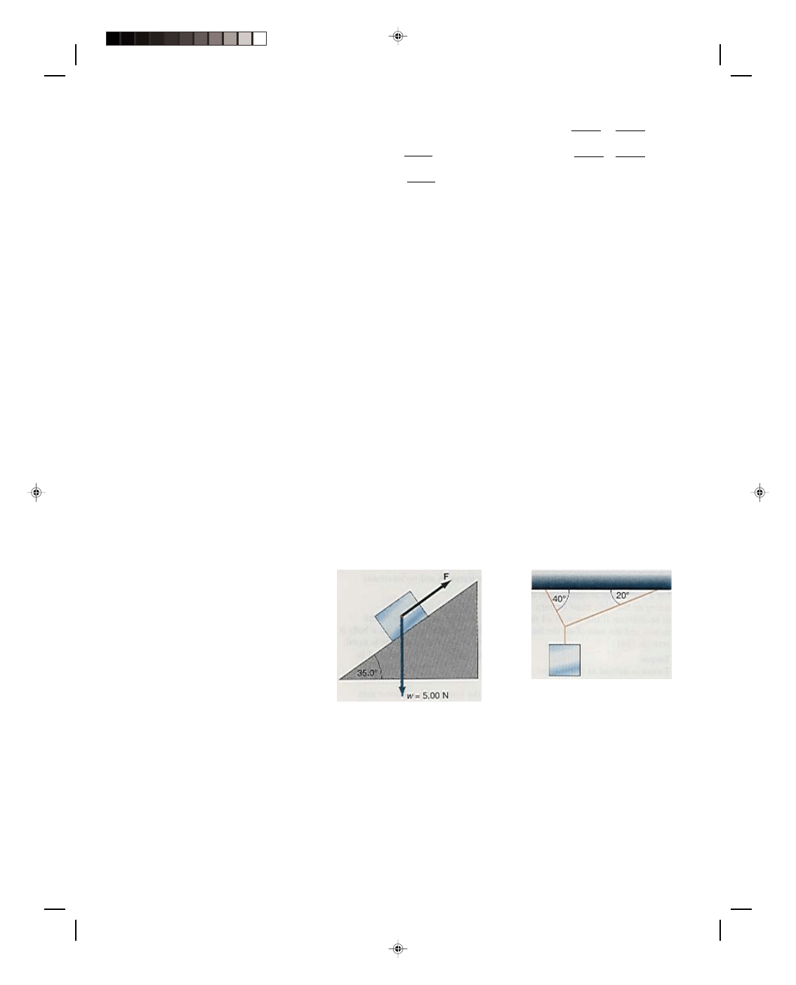
Chapter 5 Equilibrium 5-27
Torque
τ = r
⊥
F = rF
⊥
= rF sin
θ (5.21)
Second condition of equilibrium
Σ τ = 0 (5.25)
Second condition of equilibrium
Σ τ
cw
=
Σ τ
ccw
(5.24)
Center of gravity
x
cg
=
Σ w
i
x
i
(5.31)
W
y
cg
=
Σ w
i
y
i
(5.32)
W
Center of mass
x
cm
=
Σ m
i
x
i
=
Σ m
i
x
i
(5.34)
Σ m
i
M
y
cm
=
Σ m
i
y
i
=
Σ m
i
y
i
(5.35)
Σ m
i
M
Questions for Chapter 5
1. Why can a body moving at
constant velocity be considered as a
body in equilibrium?
2. Why cannot an accelerated
body be considered as in
equilibrium?
3. Why can a point outside the
body in equilibrium be considered
as an axis to compute torques?
4. What is the difference
between the center of mass of a
body and its center of gravity?
5. A ladder is resting against a
wall and a person climbs up the
ladder. Is the ladder more likely to
slip out at the bottom as the person
climbs closer to the top of the
ladder? Explain.
6. When flying an airplane a
pilot frequently changes from the
fuel tank in the right wing to the
fuel tank in the left wing. Why does
he do this?
7. Where would you expect the
center of gravity of a sphere to be
located? A cylinder?
*8. When lifting heavy objects
why is it said that you should bend
your knees and lift with your legs
instead of your back? Explain.
9. A short box and a tall box are
sitting on the floor of a truck. If the
truck makes a sudden stop, which
box is more likely to tumble over?
Why?
*10. A person is sitting at the
end of a row boat that is at rest in
the middle of the lake. If the person
gets up and walks toward the front
of the boat, what will happen to the
boat? Explain in terms of the center
of mass of the system.
11. Is it possible for the center
of gravity of a body to lie outside of
the body? (Hint: consider a
doughnut.)
*12. Why does an obese person
have more trouble with lower back
problems than a thin person?
13. Describe how a lever works
in terms of the concept of torque.
*14. Describe how you could
determine the center of gravity of
an irregular body such as a plate,
experimentally.
*15. Engineers often talk about
the moment of a force acting on a
body. Is there any difference
between the concept of a torque
acting on a body and the moment of
a force acting on a body?
Problems for Chapter 5
5.1 The First Condition of
Equilibrium
1. In a laboratory experiment
on a force table, three forces are in
equilibrium. One force of 0.300 N
acts at an angle of 40.0
0
. A second
force of 0.800 N acts at an angle of
120
0
. What is the magnitude and
direction of the force that causes
equilibrium?
2. Two ropes each 3.05 m long
are attached to the ceiling at two
points located 4.58 m apart. The
ropes are tied together in a knot at
their lower end and a load of 312 N
is hung on the knot. What is the
tension in each rope?
3. What force must be applied
parallel to the plane to make the
block move up the frictionless plane
at constant speed?
Diagram for problem 3.
4. Two ropes are attached to the
ceiling as shown, making angles of
40.0
0
and 20.0
0
. A weight of 100 N
is hung from the knot. What is the
tension in each rope?
Diagram for problem 4.
5. Find the force F, parallel to
the frictionless plane, that will
allow the system to move at
constant speed.
Pearson Custom Publishing
165
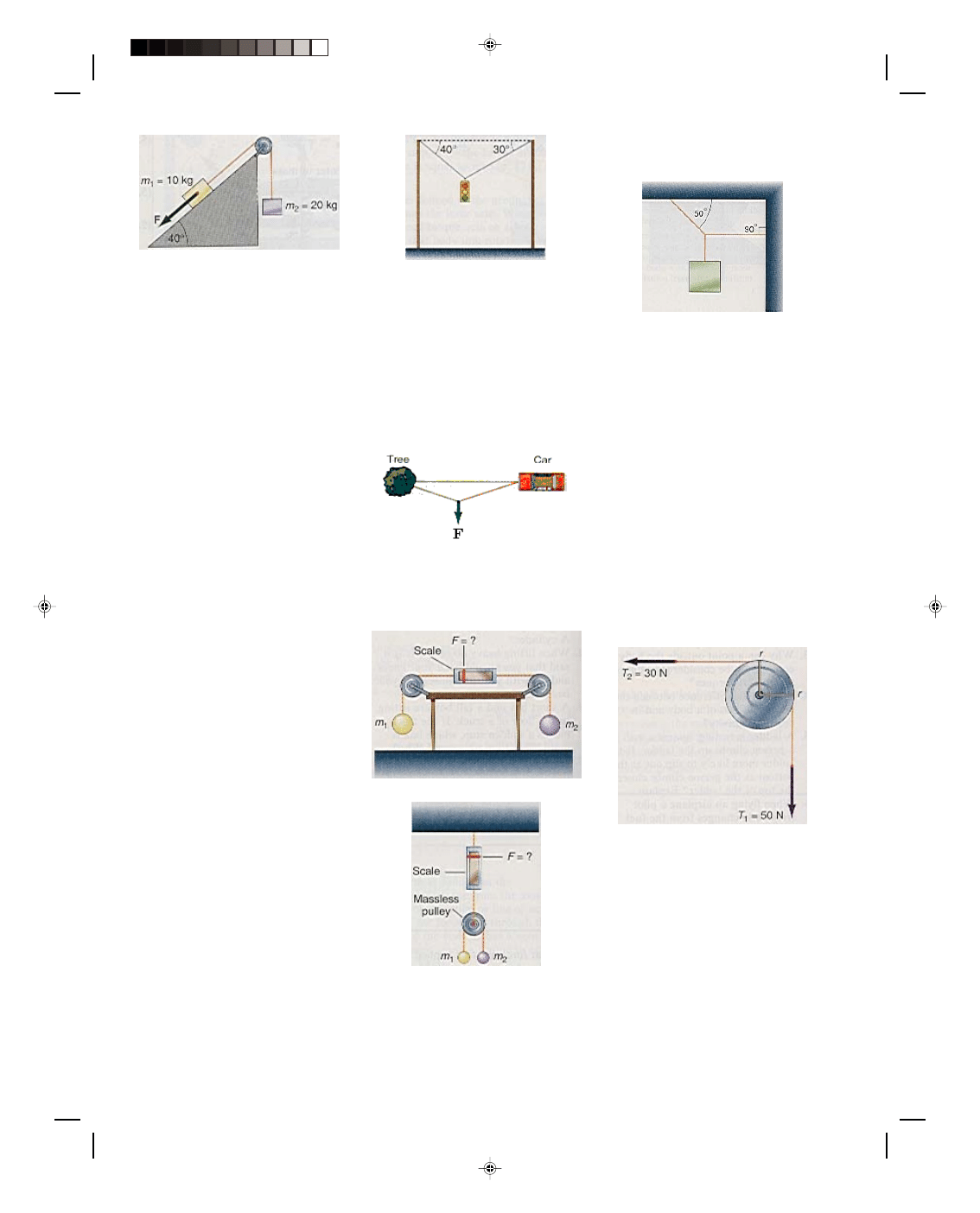
5-28 Mechanics
Diagram for problem 5.
6. A weightless rope is stretched
horizontally between two poles 7.63
m apart. Spiderman, who weighs
712 N, balances himself at the
center of the rope, and the rope is
observed to sag 0.153 m at the
center. Find the tension in each
part of the rope.
7. A weightless rope is stretched
horizontally between two poles 7.63
m apart. Spiderman, who weighs
712 N, balances himself 1.53 m
from one end, and the rope is
observed to sag 9.15 cm there. What
is the tension in each part of the
rope?
8. A force of 15.0 N is applied to
a 15.0-N block on a rough inclined
plane that makes an angle of 52.0
0
with the horizontal. The force is
parallel to the plane. The block
moves up the plane at constant
velocity. Find the coefficient of
kinetic friction between the block
and the plane.
9. With what force must a 5.00-
N eraser be pressed against a
blackboard for it to be in static
equilibrium? The coefficient of
static friction between the board
and the eraser is 0.250.
10. A traffic light, weighing 668
N is hung from the center of a cable
of negligible weight that is
stretched horizontally between two
poles that are 18.3 m apart. The
cable is observed to sag 0.610 m.
What is the tension in the cable?
11. A traffic light that weighs
600 N is hung from the cable as
shown. What is the tension in each
cable? Assume the cable to be
massless.
Diagram for problem 11.
12. Your car is stuck in a snow
drift. You attach one end of a 15.3-
m rope to the front of the car and
attach the other end to a nearby
tree, as shown in the figure. If you
can exert a force of 668 N on the
center of the rope, thereby
displacing it 0.915 m to the side,
what will be the force exerted on
the car?
Diagram for problem 12.
13. What force is indicated on
the scale in part a and part b of the
diagram if m
1
= m
2
= 20.0 kg?
(a)
(b)
Diagram for problem 13.
*14. Find the tension in each
cord of the figure, if the block
weighs 100 N.
Diagram for problem 14.
5.2 The Concept of Torque
15. A force of 4.45 N is applied
to a door knob perpendicular to a
75.0-cm. door. What torque is
produced to open the door?
16. A horizontal force of 50.0 N
is applied at an angle of 28.5
0
to a
door knob of a 75.0-cm door. What
torque is produced to open the door?
17. A door knob is placed in the
center of a 75.0-cm door. If a force of
4.45 N is exerted perpendicular to
the door at the knob, what torque is
produced to open the door?
18. Compute the net torque
acting on the pulley in the diagram
if the radius of the pulley is 0.250 m
and the tensions are T
1
= 50.0 N
and T
2
= 30.0 N.
Diagram for problem 18.
19. Find the torque produced by
the bicycle pedal in the diagram if
the force F = 11.0 N, the radius of
the crank r = 18.0 cm, and angle
θ =
37.0
0
.
Pearson Custom Publishing
166
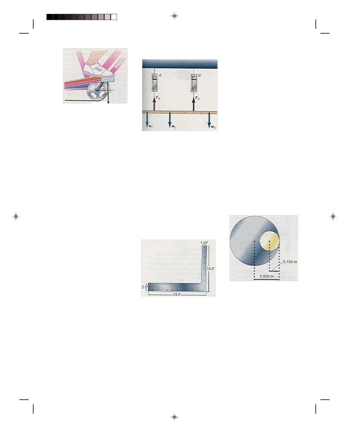
Chapter 5 Equilibrium 5-29
Diagram for problem 19.
5.5 Examples of Rigid Bodies in
Equilibrium
Parallel Forces
20. Two men are carrying a
9.00-m telephone pole that has a
mass of 115 kg. If the center of
gravity of the pole is 3.00 m from
the right end, and the men lift the
pole at the ends, how much weight
must each man support?
21. A uniform board that is 5.00
m long and weighs 450 N is
supported by two wooden horses,
0.500 m from each end. If a 800-N
person stands on the board 2.00 m
from the right end, what force will
be exerted on each wooden horse?
22. A 300-N boy and a 250-N
girl sit at opposite ends of a 4.00-m
seesaw. Where should another 250-
N girl sit in order to balance the
seesaw?
23. A uniform beam 3.50 m long
and weighing 90.0 N carries a load
of 110 N at one end and 225 N at
the other end. It is held horizontal,
while resting on a wooden horse
1.50 m from the heavier load. What
torque must be applied to keep it at
rest in this position?
24. A uniform pole 5.00 m long
and weighing 100 N is to be carried
at its ends by a man and his son.
Where should a 250-N load be hung
on the pole, such that the father
will carry twice the load of his son?
25. A meter stick is hung from
two scales that are located at the
20.0- and 70.0-cm marks of the
meter stick. Weights of 2.00 N are
placed at the 10.0- and 40.0-cm
marks, while a weight of 1.00 N is
placed at the 90.0-cm mark. The
weight of the uniform meter stick is
1.50 N. Determine the scale
readings at A and B in the diagram.
Diagram for problem 25.
Center of Gravity of a Body
26. A tapered pole 3.05 m long
weighs 111 N. The pole balances at
its mid-point when a 22.3-N weight
hangs from the slimmer end. Where
is the center of gravity of the pole?
*27. A loaded wheelbarrow that
weighs 334 N has its center of
gravity 0.610 m from the front
wheel axis. If the distance from the
wheel axis to the end of the handles
is 1.83 m, how much of the weight
of the wheelbarrow is supported by
each arm?
*28. Find the center of gravity
of the carpenters square shown in
the diagram.
Diagram for problem 28.
29. The front and rear axles of a
1110-kg car are 2.50 m apart. If the
center of gravity of the car is
located 1.15 m behind the front
axle, find the load supported by the
front and rear wheels of the car.
30. A very bright but lonesome
child decides to make a seesaw for
one. The child has a large plank,
and a wooden horse to act as a
fulcrum. Where should the child
place the fulcrum, such that the
plank will balance, when the child
is sitting on the end? The child
weighs 267 N and the plank weighs
178 N and is 3.05 m long. (Hint:
find the center of gravity of the
system.)
Center of Mass
31. Four masses of 20.0, 40.0,
60.0, and 80.0 g are located at the
respective distances of 10.0, 20.0,
30.0, and 40.0 cm from an origin.
Find the center of mass of the
system.
32. Three masses of 15.0, 45.0,
and 25.0 g are located on the x-axis
at 10.0, 25.0, and 45.0 cm. Two
masses of 25.0 and 33.0 g are
located on the y-axis at 35.0 and
50.0 cm, respectively. Find the
center of mass of the system.
*33. A 1.00-kg circular metal
plate of radius 0.500 m has
attached to it a smaller circular
plate of the same material of 0.100
m radius, as shown in the diagram.
Find the center of mass of the
combination with respect to the
center of the large plate.
Diagram for problem 33.
*34. This is the same problem
as 33 except the smaller circle of
material is removed from the larger
plate. Where is the center of mass
now?
Crane Boom Problems
35. A horizontal uniform boom
that weighs 200 N and is 5.00 m
long supports a load w
L
of 1000 N,
as shown in the figure. Find all the
forces acting on the boom.
Pearson Custom Publishing
167
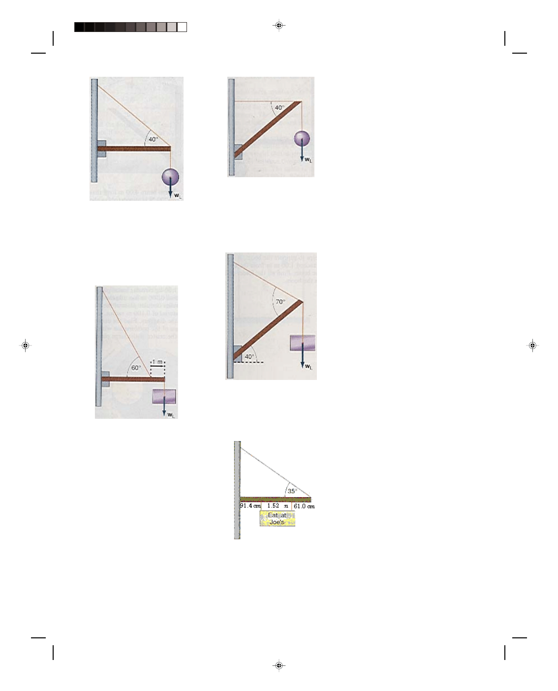
5-30 Mechanics
Diagram for problem 35.
36. A horizontal, uniform boom
4.00 m long that weighs 200 N
supports a load w
L
of 1000 N. A guy
wire that helps to support the
boom, is attached 1.00 m in from
the end of the boom. Find all the
forces acting on the boom.
Diagram for problem 36.
37. A horizontal, uniform boom
4.50 m long that weighs 250 N
supports a 295 N load w
L
. A guy
wire that helps to support the boom
is attached 1.0 m in from the end of
the boom, as in the diagram for
problem 40. If the maximum
tension that the cable can
withstand is 1700 N, how far out on
the boom can a 95.0-kg repairman
walk without the cable breaking?
38. A uniform beam 4.00 m long
that weighs 200 N is supported, as
shown in the figure. The boom lifts
a load w
L
of 1000 N. Find all the
forces acting on the boom.
Diagram for problem 38.
*39. A uniform beam 4.00 m
long that weighs 200 N is
supported, as shown in the figure.
The boom lifts a load w
L
of 1000 N.
Find all the forces acting on the
boom.
Diagram for problem 39.
40. A 356-N sign is hung on a
uniform steel pole that weighs 111
N, as shown in the figure. Find all
the forces acting on the boom.
Diagram for problem 40.
Ladder Problems
41. A uniform ladder 6.00 m
long weighing 120 N leans against a
frictionless wall. The base of the
ladder is 1.00 m away from the
wall. Find all the forces acting on
the ladder.
42. A uniform ladder 6.00 m
long weighing 120 N leans against a
frictionless wall. A girl weighing
400 N climbs three-fourths of the
way up the ladder. If the base of the
ladder makes an angle of 75.0
0
with
the ground, find all the forces
acting on the ladder. Compute all
torques about the base of the
ladder.
43. Repeat problem 42, but
compute all torques about the top of
the ladder. Is there any difference
in the results of the problem?
44. A uniform ladder 4.58 m
long weighing 111 N leans against a
frictionless wall. If the base of the
ladder makes an angle of 40.0
0
with
the ground, what is the minimum
coefficient of friction between the
ladder and the ground such that the
ladder will not slip out?
*45. A uniform ladder 5.50 m
long with a mass of 12.5 kg leans
against a frictionless wall. The base
of the ladder makes an angle of
48.0
0
with the ground. If the
coefficient of friction between the
ladder and the ground is 0.300, how
high can a 82.3-kg man climb the
ladder before the ladder starts to
slip?
Applications to the Health
Sciences
46. A weight lifter is lifting a
dumbbell as in the example shown
in figure 5.22 only now the forearm
makes an angle of 30.0
0
with the
horizontal. Using the same data as
for that problem find the force F
M
exerted by the biceps muscle and
the reaction force at the elbow joint
F
J
. Assume that the force F
M
remains perpendicular to the arm.
47. Consider the weight lifter in
the example shown in figure 5.23.
Determine the forces F
M
and F
R
if
the angle
θ = 00.0
0
.
*48. The weight of the upper
body of the person in the
accompanying diagram acts
downward about 8.00 cm in front of
the fifth lumbar vertebra. This
weight produces a torque about the
fifth lumbar vertebra. To
Pearson Custom Publishing
168
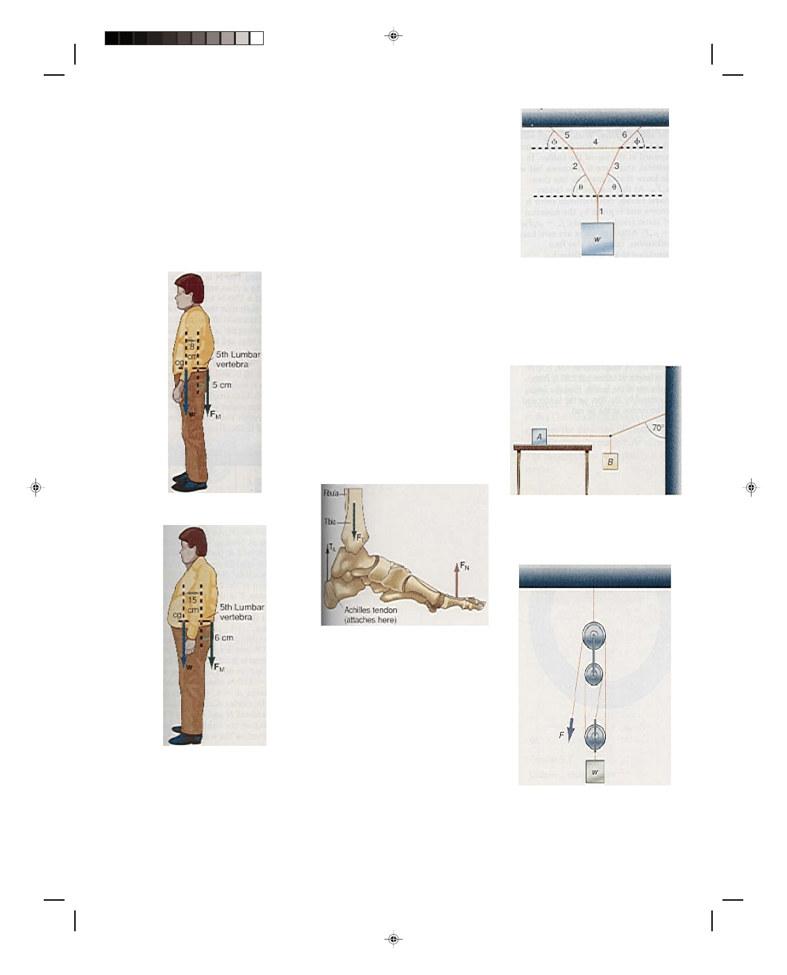
Chapter 5 Equilibrium 5-31
counterbalance this torque the
muscles in the lower back exert a
force F
M
that produces a counter
torque. These muscles exert their
force about 5.00 cm behind the fifth
lumbar vertebra. If the person
weighs 801 N find the force exerted
by the lower back muscles F
M
and
the reaction force F
R
that the
sacrum exerts upward on the fifth
lumbar vertebra. The weight of the
upper portion of the body is about
65% of the total body weight.
Diagram for problem 48.
Diagram for problem 49.
*49. Consider the same
situation as in problem 48 except
that the person is overweight. The
center of gravity with the additional
weight is now located 15.0 cm in
front of the fifth lumbar vertebra
instead of the previous 8.00 cm.
Hence a greater torque will be
exerted by this additional weight.
The distance of the lower back
muscles is only slightly greater at
6.00 cm. If the person weighs 1070
N find the force F
R
on the fifth
lumbar vertebra and the force F
M
exerted by the lower back muscles.
*50. A 668-N person stands
evenly on the balls of both feet. The
Achilles tendon, which is located at
the back of the ankle, provides a
tension T
A
to help balance the
weight of the body as seen in the
diagram. The distance from the ball
of the foot to the Achilles tendon is
approximately 18.0 cm. The tibia
leg bone pushes down on the foot
with a force F
T
. The distance from
the tibia to the ball of the foot is
about 14.0 cm. The ground exerts a
reaction force F
N
upward on the ball
of the foot that is equal to half of
the body weight. Draw a free body
diagram of the forces acting and
determine the force exerted by the
Achilles tendon and the tibia.
Diagram for problem 50.
Additional Problems
*51. If w weighs 100 N, find
(a) the tension in ropes 1, 2, and 3
and (b) the tension in ropes 4, 5,
and 6. The angle
θ = 52.0
0
and the
angle
φ = 33.0
0
.
Diagram for problem 51.
*52. Block A rests on a table
and is connected to another block B
by a rope that is also connected to a
wall. If M
A
= 15.0 kg and
µ
s
= 0.200,
what must be the value of M
B
to
start the system into motion?
Diagram for problem 52.
53. In the pulley system shown,
what force F is necessary to keep
the system in equilibrium?
Diagram for problem 53.
Pearson Custom Publishing
169
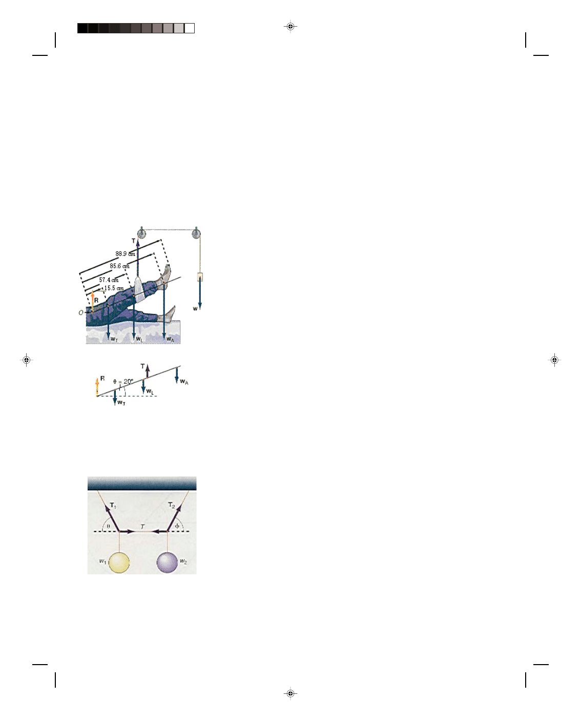
5-32 Mechanics
*54. A sling is used to support a
leg as shown in the diagram. The
leg is elevated at an angle of 20.0
0
.
The bed exerts a reaction force R on
the thigh as shown. The weight of
the thigh, leg, and ankle are given
by w
T
= 192 N, w
L
= 85.4 N, and w
A
= 30.1 N, respectively, and the
locations of these weights are as
shown. The sling is located 68.6 cm
from the point O in the diagram. A
free body diagram is shown in part
b of the diagram. Find the weight w
that is necessary to put the leg into
equilibrium.
(a)
(b)
Diagram for problem 54.
*55. Find the tensions T
1
, T,
and T
2
in the figure if w
1
= 500 N
and w
2
= 300 N. The angle
θ = 35.0
0
and the angle
φ = 25.0
0
.
Diagram for problem 55.
*56. The steering wheel of an
auto has a diameter of 45.7 cm. The
axle that it is connected to has a
diameter of 5.08 cm If a force of 111
N is exerted on the rim of the
wheel, (a)
what is the torque
exerted on the steering wheel,
(b) what is the torque exerted on
the axle, and (c)
what force is
exerted on the rim of the axle?
57. One type of simple machine
is called a wheel and axle. A wheel
of radius 35.0 cm is connected to an
axle of 2.00 cm radius. A force of F
in
= 10.0 N is applied tangentially to
the wheel. What force F
out
is
exerted on the axle? The ratio of the
output force F
out
to the input force
F
in
is called the ideal mechanical
advantage (IMA) of the system.
Find the IMA of this system.
*58. A box 1.00 m on a side
rests on a floor next to a small piece
of wood that is fixed to the floor.
The box weighs 500 N. At what
height h should a force of 400 N be
applied so as to just tip the box?
*59. A 200-N door, 0.760 m wide
and 2.00 m long, is hung by two
hinges. The top hinge is located
0.230 m down from the top, while
the bottom hinge is located 0.330 m
up from the bottom. Assume that
the center of gravity of the door is
at its geometrical center. Find the
horizontal force exerted by each
hinge on the door.
*60. A uniform ladder 6.00 m
long weighing 100 N leans against a
frictionless wall. If the coefficient of
friction between the ladder and the
ground is 0.400, what is the
smallest angle
θ that the ladder can
make with the ground before the
ladder starts to slip?
*61. If an 800-N man wants to
climb a distance of 5.00 m up the
ladder of problem 60, what angle
θ
should the ladder make with the
ground such that the ladder will not
slip?
*62. A uniform ladder 6.10 m
long weighing 134 N leans against a
rough wall, that is, a wall where
there is a frictional force between
the top of the ladder and the wall.
The coefficient of static friction is
0.400. If the base of the ladder
makes an angle
θ of 40.0
0
with the
ground when the ladder begins to
slip down the wall, find all the
forces acting on the ladder. (Hint:
With a rough wall there will be a
vertical force f
s
acting upward at
the top of the ladder. In general,
this force is unknown but we do
know that it must be less than
µ
s
F
N
.
At the moment the ladder starts to
slip, this frictional force is known
and is given by the equation of
static friction, namely, f
s
=
µ
s
F
N
=
µ
s
F. Although there are now four
unknowns, there are also four
equations to solve for them.)
*63. A 1000-N person stands
three-quarters of the way up a
stepladder. The step side weighs
89.0 N, is 1.83 m long, and is
uniform. The rear side weighs 44.5
N, is also uniform, and is also 1.83
m long. A hinge connects the front
and back of the ladder at the top. A
weightless tie rod, 45.8 cm in
length, is connected 61.0 cm from
the top of the ladder. Find the
forces exerted by the floor on the
ladder and the tension in the tie
rod.
Interactive Tutorials
64. Concurrent Forces. Two
ropes are attached to the ceiling,
making angles
θ = 20.0
0
and
φ =
40.0
0
, suspending a mass m = 50.0
kg. Calculate the tensions T
1
and T
2
in each rope.
65. Parallel Forces. A uniform
beam of length L = 10.0 m and mass
m = 5.00 kg is held up at each end
by a force F
A
(at 0.00 m) and force
F
B
(at 10.0 m). If a weight W = 400
N is placed at the position x = 8.00
m, calculate forces F
A
and F
B
.
66. The crane boom. A uniform
boom of weight w
B
= 250 N and
length l = 8.00 m is connected to the
mast by a hinge pin at the point A
in figure 5.20. A load w
L
= 1200 N is
supported at the other end. A cable
is connected at the end of the boom
making an angle
θ = 55.0
0
, as
shown in the diagram. Find the
tension T in the cable and the
vertical V and horizontal H forces
that the hinge pin exerts on the
boom.
67. A uniform ladder. A uniform
ladder of weight w
1
= 100 N and
length L = 20.0 m leans against a
frictionless wall at a base angle
θ =
Pearson Custom Publishing
170

Chapter 5 Equilibrium 5-33
60.0
0
. A person weighing w
p
= 150
N climbs the ladder a distance d =
6.00 m from the base of the ladder.
Calculate the horizontal H and
vertical V forces acting on the
ladder, and the force F exerted by
the wall on the top of the ladder.
Tutorials click on this sentence.
To go to another chapter, return to the table of contents by clicking on this sentence.
Pearson Custom Publishing
171

Pearson Custom Publishing
172
Wyszukiwarka
Podobne podstrony:
Fundamentals of College Physics Chapter 08
Fundamentals of College Physics Chapter 17
Fundamentals of College Physics Chapter 03
Fundamentals of College Physics Chapter 15
Fundamentals of College Physics Chapter 04
Fundamentals of College Physics Chapter 12
Fundamentals of College Physics Chapter 11
Fundamentals of College Physics Chapter 02
Fundamentals of College Physics Chapter 01
Fundamentals of College Physics Chapter 10
Fundamentals of College Physics Chapter 16
Fundamentals of College Physics Chapter 13
Fundamentals of College Physics Chapter 07
Fundamentals of College Physics Chapter 14
Fundamentals of Anatomy and Physiology 05 Chapter
Fundamentals of Statistics 2e Chapter08
Feynman Lectures on Physics Volume 1 Chapter 05
Fundamentals of radiation dosimetry and radiological physics
Fundamentals of Anatomy and Physiology 22 Chapter
więcej podobnych podstron