
Project No. NCHRP 12-52 COPY
NO.
_____
AASHTO-LRFD DESIGN EXAMPLE
HORIZONTALLY CURVED STEEL BOX GIRDER BRIDGE
FINAL REPORT
Prepared for
National Cooperative Highway Research Program
Transportation Research Board
National Research Council
John M. Kulicki
Wagdy G. Wassef
Christopher Smith
Kevin Johns
Modjeski and Masters, Inc.
Harrisburg, Pennsylvania
October 2005

ACKNOWLEDGMENT OF SPONSORSHIP
This work was sponsored by the American Association of State Highway and
Transportation Officials, in cooperation with the Federal Highway Administration, and was
conducted in the National Cooperative Highway Research Program which is administered by the
Transportation Research Board of the National Research Council.
DISCLAIMER
This is an uncorrected draft as submitted by the research agency. The opinions and
conclusions expressed or implied in the report are those of the research agency. They are not
necessarily those of the Transportation Research Board, the National Research Council, or the
Federal Highway Administration, the American Association of State Highway and
Transportation Officials, or of the individual states participating in the National Cooperative
Highway Research Program.

Project No. NCHRP 12-52
AASHTO-LRFD DESIGN EXAMPLE
HORIZONTALLY CURVED STEEL BOX GIRDER BRIDGE
FINAL REPORT
Prepared for
National Cooperative Highway Research Program
Transportation Research Board
National Research Council
John M. Kulicki
Wagdy G. Wassef
Christopher Smith
Kevin Johns
Modjeski and Masters, Inc.
Harrisburg, Pennsylvania
October 2005

(This page is intentionally left blank.)

iii
TABLE OF CONTENTS
TABLE OF CONTENTS ............................................................................................................ iii
LIST OF FIGURES ..................................................................................................................... vi
LIST OF TABLES ...................................................................................................................... vii
PREFACE..................................................................................................................................... ix
OBJECTIVES ................................................................................................................................1
DESIGN PARAMETERS .............................................................................................................2
STEEL FRAMING ........................................................................................................................3
Girder Depth ......................................................................................................................3
Internal and External Bracing..........................................................................................3
Bracing of Tub Flanges .....................................................................................................4
Longitudinal Flange Stiffener...........................................................................................5
Field Section .......................................................................................................................5
ANALYSES ....................................................................................................................................6
Loading Combinations ......................................................................................................6
Three-Dimensional Finite Element Analyses ..................................................................7
LOADS............................................................................................................................................8
Dead Load...........................................................................................................................8
Live Load ............................................................................................................................8
LIMIT STATES .............................................................................................................................9
Strength...............................................................................................................................9
Constructibility ..................................................................................................................9
Fatigue.................................................................................................................................9
Live Load Deflection........................................................................................................10
DESIGN ........................................................................................................................................11
Section Properties ............................................................................................................11
Shear Connectors.............................................................................................................11
Flanges ..............................................................................................................................11
Webs ................................................................................................................................12
Diaphragms ......................................................................................................................12
Sample Calculations ........................................................................................................12

iv
APPENDIX A Girder Field Sections .................................................................................. A-1
APPENDIX B Girder Moments, Shears, and Torques at Tenth-Points..........................B-1
APPENDIX C Selected Design Forces and Girder 2 Section Properties .........................C-1
APPENDIX D Sample Calculations ................................................................................... D-1
Girder Stress Check Section 1-1 G2 Node 10
Girder Section Proportioning.............................................................................. D-3
Girder Stress Check Section 1-1 G2 Node 10
Constructibility - Web ........................................................................................ D-4
Girder Stress Check Section 1-1 G2 Node 10
Constructibility - Top Flange in Compression ................................................... D-6
Girder Stress Check Section 1-1 G2 Node 10
Strength - Ductility Requirement...................................................................... D-13
Girder Stress Check Section 5-5 G1 Node 36
Constructibility - Top Flange in Tension.......................................................... D-15
Girder Stress Check Section 1-1 G1 Node 9
Constructibility - Top Flange in Compression ................................................. D-16
Girder Stress Check Section 1-1 G1 Node 9
Constructibility - Top Flange in Tension.......................................................... D-18
Girder Stress Check Section 1-1 G2 Node 10
Fatigue - Bottom Flange ................................................................................... D-19
Girder Stress Check Section 1-1 G2 Node 10
Fatigue - Shear Connectors............................................................................... D-20
Girder Stress Check Section 8-8 G2 Node 48
Shear Connectors - Maximum Transverse Spacing.......................................... D-23
Girder Stress Check Section 5-5 G2 Node 36
Strength - Bottom Flange.................................................................................. D-25
Girder Stress Check Section 5-5 G2 Node 36
Longitudinal Flange Stiffener........................................................................... D-33
Girder Stress Check Section 5-5 G2 Node 36
Design of Internal Diaphragm .......................................................................... D-34
Girder Stress Check Section 5-5 G2 Node 36
Design of Bearing Stiffener .............................................................................. D-37
Girder Stress Check G2 Span 1 Bay 1
Top Flange Bracing Member Design - Constructibility ................................... D-40
Girder Stress Check Section 5-5 G2 Node 36
Transverse Bending Stress................................................................................ D-44
Girder Stress Check Section 2-2 G2 Node 20.3
Stresses............................................................................................................. D-49
Girder Stress Check Section 2-2 G2 Node 20.3
Strength - Bottom Flange.................................................................................. D-51
Bolted Splice Design Section 2-2 G2 Node 20.3

v
Design Action Summary and Section Information........................................... D-54
Bolted Splice Design Section 2-2 G2 Node 20.3
Constructibility - Top Flange............................................................................ D-57
Bolted Splice Design Section 2-2 G2 Node 20.3
Constructibility - Bottom Flange ...................................................................... D-59
Bolted Splice Design Section 2-2 G2 Node 20.3
Strength - Top and Bottom Flange ................................................................... D-61
Bolted Splice Design Section 2-2 G2 Node 20.3
Constructibility - Web ...................................................................................... D-67
Bolted Splice Design Section 2-2 G2 Node 20.3
Strength - Web .................................................................................................. D-70
Bolted Splice Design Section 2-2 G2 Node 20.3
Splice Plates...................................................................................................... D-74
APPENDIX E Tabulation of Various Stress Checks .........................................................E-1

vi
LIST OF FIGURES
Figure 1. Box Girder Bridge Cross Section...................................................................................13
Figure 2. Node Numbers................................................................................................................14
Figure 3. Double-Diagonal Bracing: Lateral Flange Moments (k-ft) and Bracing Forces (kips) Due
to Deck Weight with Overhang Brackets, Inclined Webs ..............................................15
Figure 4. Single-Diagonal Bracing: Lateral Flange Moments (k-ft) and Bracing Forces (kips) Due
to Entire Deck Weight with Overhang Brackets, Inclined Webs ...................................16
Figure 5. Single-Diagonal Bracing: Lateral Flange Moments (k-ft) and Bracing Forces (kips) Due
to Cast #1 with Overhang Brackets, Inclined Webs .......................................................17
Figure D-1. Overhang Bracket Loading ................................................................................... D-81
Figure D-2. Diaphragm and Bearing Stiffener at Pier of Girder 2, Looking Upstation ........... D-81
Figure D-3. Composite Box Cross Section, Girder 2 ............................................................... D-82
Figure D-4. Effective Width of Web Plate, d
o
, with Transverse Stiffener ............................... D-82
Figure D-5. Bolt Patterns for Top and Bottom Flange ............................................................. D-83
Figure D-6. Bolt Pattern for Web ............................................................................................. D-84

vii
LIST OF TABLES
Table C-1. Selected Unfactored Moments (k-ft) and Web Fatigue Shears (kips), Girder 2 ......C-3
Table C-2. Shear (kips), Girder 2 Span 1 at Tenth-Points...........................................................C-4
Table C-3. Selected Unfactored Torque (k-ft), Girder 2 .............................................................C-5
Table C-4. Top Flange Bracing Forces (kips), Girder 2 Span 1..................................................C-6
Table C-5. Selected Section Properties for Girder 2 ...................................................................C-7
Table D-1. Strength Limit State at 100 feet from Left Abutment ............................................ D-85
Table D-2. Constructibility Limit State at 100 feet from Left Abutment................................. D-85
Table D-3. Unfactored Actions................................................................................................. D-86
Table D-4. Tub Cross Section................................................................................................... D-86
Table E-1. Constructibility – Top Flange ....................................................................................E-4
Table E-2. Constructibility – Web, Box Girder 2........................................................................E-4
Table E-3. Strength – Bottom Flange, Box Girder 2 ...................................................................E-5
Table E-4. Maximum Pricipal Stresses – Bottom Flange, Box Girder 2.....................................E-5

viii
(This page is intentionally left blank.)

ix
PREFACE
AASHTO first published Guide Specifications for Horizontally Curved Highway Bridges in
1980. These Guide Specifications included Allowable Stress Design (ASD) provisions developed
by the Consortium of University Research Teams (CURT) and approved by ballot of the AASHTO
Highway Subcommittee on Bridges and Structures in November 1976. CURT consisted of
Carnegie-Mellon University, the University of Pennsylvania, the University of Rhode Island and
Syracuse University. The 1980 Guide Specifications also included Load Factor Design (LFD)
provisions developed in American Iron and Steel Institute (AISI) Project 190 and approved by ballot
of the AASHTO Highway Subcommittee on Bridges and Structures (HSCOBS) in October 1979.
The Guide Specifications covered both I and box girders.
Changes to the 1980 Guide Specifications were included in the AASHTO Interim
Specifications - Bridges for the years 1981, 1982, 1984, 1985, 1986, and 1990. A new version of the
Guide Specifications for Horizontally Curved Highway Bridges was published in 1993. It included
these interim changes, and additional changes, but did not reflect the extensive research on curved-
girder bridges that has been conducted since 1980 or many important changes in related provisions
of the straight-girder specifications.
As a result of the research work on curved bridges conducted by the FHWA and several
research institutes, design provisions for both straight and curved bridges were developed. As part
of the NCHRP 12-52 project, these design provisions were incorporated into the AASHTO-LRFD
Bridge Design Specifications in two stages. The design provisions for straight bridges were
approved by ballot of the HSCOBS in 2003 and were incorporated into the third edition of the
AASHTO-LRFD Bridge Design Specifications, published in 2004. The design provisions for
curved bridges were approved by ballot of the HSCOBS in 2004 and are to be published as part of
the 2005 Interim Specifications to the AASHTO-LRFD Bridge Design Specifications.
This Horizontally Curved Steel Box Girder Bridge Design Example was originally developed
in the NCHRP 12-38 project using the 1993 AASHTO Guide Specifications for Horizontally Curved
Steel Girder Bridges. It was updated to illustrate the applicability of the revisions to the AASHTO-
LRFD Bridge Design Specifications included in the 2005 Interim Specifications which were meant
to incorporate curved bridges. As in the NCHRP 12-38 example, a composite bottom flange option
is provided for the bottom flange in the negative moment regions. This Design Example was
compiled as a part of the deliverables in National Cooperative Highway Research Program Project
12-52.
The following terms are used to identify particular specifications:
• ANSI/AASHTO/AWS refers to the 2002 edition of D1.5:2002 Bridge Welding Code,
American Welding Society and 2003 Interim Specifications,
• LFD/ASD refers to the current year AASHTO Standard Specifications for Highway Bridges,

x
17th edition and Interim Specifications and
• LRFD refers to the 2003 AASHTO-LRFD Bridge Design Specifications, Third Edition, with
the 2005 Interims. Article and equation numbers in this example refer to those of the
AASHTO-LRFD Specifications.

1
OBJECTIVES
Using the 2004 AASHTO-LRFD Bridge Design Specifications with the 2005 Interim
Specifications (hereafter referred to as the LRFD Specifications), design a three-span horizontally
curved steel box girder bridge with two tub girders in the cross section.

2
DESIGN PARAMETERS
The bridge has spans of 160-210-160 feet measured along the centerline of the bridge. Span
lengths are arranged to give relatively equal positive dead load moments in the end and center spans.
The radius of the bridge is 700 feet at the center of the roadway.
Out-to-out deck width is 40.5 feet. There are three 12-foot traffic lanes. Supports are radial
with respect to the roadway. There are two tub girders in the cross section.
Structural steel having a specified minimum yield stress of 50 ksi is used throughout. The
deck is conventional cast-in-place concrete with a specified minimum 28-day compressive strength
of 4,000 psi. The structural deck thickness is 9.5 inches (no integral wearing surface is assumed).
The deck haunch is 4.0 inches deep measured from the top of the web to the bottom of the deck.
The width of the haunch is assumed to be 20.0 inches. A future wearing surface of 30 psf is
specified. Parapets are each assumed to weigh 495 plf.
The roadway is superelevated 5 percent.
Live load used is the HL-93. Live load for fatigue is taken as defined in Article 3.6.1.4 of the
LRFD Specifications. The bridge is designed for a 75-year fatigue life. The bridge site is assumed
to be located in earthquake Zone A so earthquake loading need not be considered.
Sequential placement of the concrete deck is considered. Permanent steel deck forms are
assumed to be used between the two girders and between the flanges of the individual tubs; the
forms are assumed to weigh 15 psf.

3
STEEL FRAMING
The steel framing consists of two trapezoidal tub girders with the tops of the webs in each tub
spaced 10 feet apart at the top of the tub and with a clear deck span of 12.5 feet between the top of
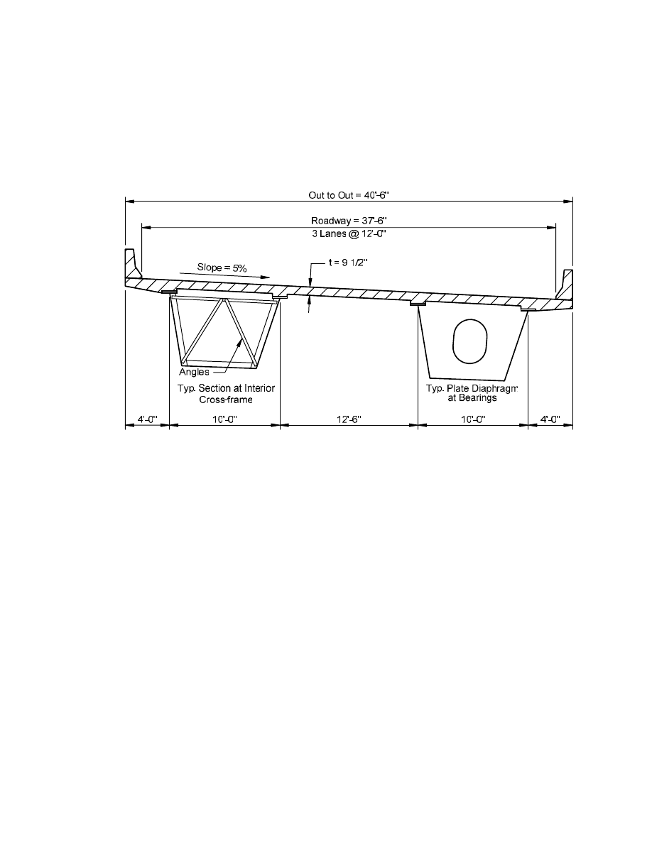
the interior webs of the two tubs. The cross section is shown in Figure 1. Two bearings set one foot
inside of each web are used under each box at each support, as permitted in Article 6.11.1.2.4.
Girder Depth
For I-beams Article 2.5.2.6.3 provides for a preferred minimum depth limit of 0.04 of the
span of the girder, L, for simple spans and 0.032L for continuous spans. There is no explicit limit
given for steel box beams. The longest effective span length (either end or interior span) controls.
The length of the center span of the outside girder, G2, is 213.38 feet (measured along the
longitudinal centerline of the box), which is the girder with the longest effective span in this
example. Therefore, the recommended girder depth is computed as 0.032(213.38)(12) = 81.9 in.
The actual vertical web depth is 78 inches, which is slightly less than the preferred minimum depth.
However, box girders are generally stiffer than I-girders because an individual box nearly acts as
two I-girders for vertical bending. For torsion, an individual box girder is significantly stiffer than
two I-girders.
The slope of the webs is one-on-four, which is the limit given in Article 6.11.2.1.1. As a
result, the width of the bottom flange of each tub is 81 inches between webs. The actual box flange
width is 83 inches to provide a 1-inch lip outside of each web, which is needed for welding of the
webs to the bottom flange.
Internal and External Bracing
The boxes are braced internally at intermediate locations with K-frames. The internal K-
frames are spaced longitudinally at approximately 16 feet (measured along the centerline of the
bridge). At locations where a longitudinal flange stiffener is not used, the transverse bracing
members are attached to the bottom flange. At these locations, the bottom strut of the K-frame is
assumed in this example to be welded to the bottom flange and bolted to the connection plates on the
webs. At locations where a longitudinal flange stiffener is used, the bottom strut is assumed to be
bolted to the top of the longitudinal stiffener and to the connection plates on the webs. The cross
frames are assumed to be single-angle members bolted to connection plates. The working points are
assumed to be located as close to the flange-web intersections as practical, except where the
longitudinal flange stiffening causes the bracing to be offset from the flange.
Design of the internal cross bracing members is not shown in this example. It was
determined from the analysis that the largest factored load in any of the internal cross frame
members on the bridge is 80 kips in the diagonal members located at Nodes 11 and 12 in Span 1.
Cross frame members were modeled as truss members in the analysis, with a cross-sectional area of
5.0 square inches. Article 6.7.4.3 specifies that the cross-sectional area and stiffness of the top and
bottom transverse bracing members not be smaller than the area and stiffness of the diagonal
members. In addition, at locations where a longitudinal flange stiffener is present, the moment of
inertia of the transverse bracing member should equal or exceed the moment of inertia of the

4
longitudinal stiffener taken about the base of the stiffener.
The largest range of stress due to fatigue loading in the internal cross frames was found to be
approximately 15 ksi. This maximum stress range was determined by passing the factored fatigue
truck defined in Article 3.6.1.4 over the left and right web of a tub, resulting in a reversal of stress in
each member. The fatigue stress range, i.e. sum of the absolute values of the maximum tensile and
compressive stresses, was approximately 15 ksi. According to Table 3.4.1-1, only 75 percent of the
stress range so determined is used to check fatigue for transverse members. Thus, the design fatigue
stress range is approximately 11 ksi. The fatigue category of these member end connections is
Category E. The design stress range exceeds the nominal fatigue resistance of 2.25 ksi specified for
a Category E detail according to Article 6.6.1.2. The value of 2.25 ksi is equal to one-half of the
constant-amplitude fatigue threshold of 4.5 ksi specified for a Category E detail in Table 6.6.1.2.5-3
of AASHTO-LRFD. This value is used whenever the fatigue strength is governed by the constant-
amplitude fatigue threshold, which is assumed to be the case in this example. Since the design
fatigue stress range exceeds the nominal fatigue resistance for a fatigue Category E detail, fillet
welds cannot be used for these member connections in this particular case.
As required in Article 6.7.4.3, there are full-depth internal and external diaphragms provided
at support lines, but there are no other external braces provided between the boxes in this example.
For the analysis, the diaphragm plates for both the internal and external diaphragms were assumed to
be 0.5 inches thick. The external diaphragms were assumed to have top and bottom flanges with an
area of 8.0 square inches for each flange.
Bracing of Tub Flanges
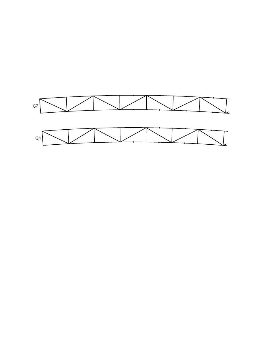
The top flanges of the individual tubs are braced with single members placed diagonally
between the tub flanges. Figure 2 shows the arrangement of the top diagonal bracing in each girder.
Figure 2 also gives the node numbers for part of Span 1 so that the locations can be related to
subsequent sample design calculations given in Appendix D. The bracing is assumed to be directly
connected to the flanges at each internal cross frame, i.e. in the plane of the flange, as required in
Article 6.7.5.1. These top flange bracing members provide torsional continuity to the box before the
deck cures, and therefore, must have adequate resistance to resist the torsional shear flow in the non-
composite section at the constructibility limit state. One end of each internal cross frame does not
have lateral bracing attached. The tub flanges tend to develop larger lateral flange bending stresses
at the points where the lateral bracing is not connected because the top flange must provide the
majority of the torsional resistance. Top flange bracing should be continuous along the length of the
girder to ensure that the top flanges are not required to resist the entire torsion at any one location.
There are several causes of the lateral moments in the top flanges including curvature,
inclination of the webs and overhang bracket loads. The effect of curvature can be conservatively
estimated using Equation C4.6.1.2.4b-1. The inclination of the webs causes a radial force, which
must be resisted by the flanges. On the exterior of the bridge, a portion of the deck weight is applied
to overhang brackets, which results in a radial tensile force on the outside top flanges and an
opposite force on the bottom flange.
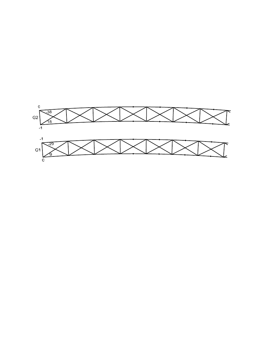
The single top flange lateral bracing members used in the design example cause the lateral
flange moments to vary depending on whether or not the brace is connected to an interior or exterior

5
flange. To illustrate, both single-diagonal and double-diagonal (or X) top-flange bracing
arrangements were analyzed using a 3D finite-element model assuming inclined webs. The lateral
flange moments in the two top flanges, and in some cases, the forces in the top flange bracing
members in part of Span 1 due to the entire deck weight and Cast #1 (with the effect of the overhang
brackets considered in each case) are reported in Figures 3 through 5. Half of the overhang weight
was assumed to be applied to the brackets in the analysis, as shown in Figure D-1 (Appendix D). In
Figures 3 through 5, the lateral flange moments are shown above and below the top flanges of each
girder, whereas the axial forces in the top chord of the internal K-braces and in the top lateral
bracing are shown near the appropriate members. Note that the inverted K-bracing inside the boxes
results in two top chord members across the tub in the finite-element model. Figure 3 shows the
results for the case of the entire deck weight applied to the boxes and overhang brackets assuming
double top flange lateral bracing and inclined webs. Figure 4 shows similar results for the case
assumed in the design example (single-diagonal top flange lateral bracing and inclined webs) under
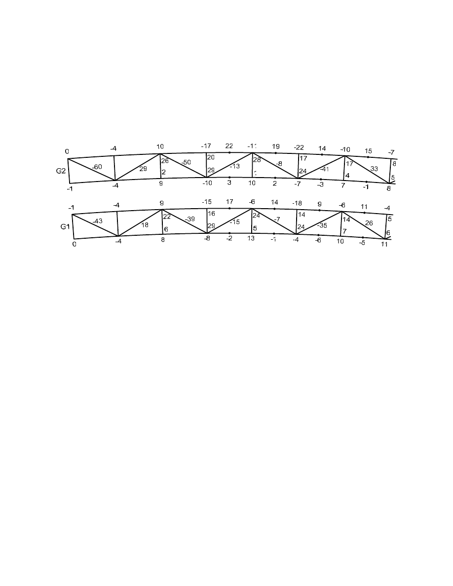
the loading due to the entire deck weight. Finally, Figure 5 shows the results due to Cast #1 for the
single-diagonal bracing case with inclined webs (again the case assumed in the design example).
This loading case causes larger girder moments and bracing forces in Span 1 than does the entire
deck load because the load in Span 2 tends to counter the load in Span 1.
From examination of the results shown in Figures 3 through 5, the single-diagonal bracing
pattern chosen for the design example results in the largest lateral flange bending moments and
bracing member forces. While these effects are reduced somewhat when double-diagonal bracing is
utilized, additional bracing members and connections are required. A suggested solution is to utilize
parallel single-diagonal bracing members in each bay, which would result in lower lateral flange
bending moments in combination with fewer members and connections.
Longitudinal Flange Stiffener
A single longitudinal flange stiffener is used on the box flanges over the negative moment
sections. The longitudinal stiffener is terminated at the bolted field splices in Spans 1, 2 and 3. By
terminating the longitudinal flange stiffener at the bolted splices, there is no need to consider fatigue
at the terminus of the stiffener. The bottom flange splice plates inside the box must be split to
permit the stiffener to extend to the free edge of the flange where the longitudinal stress is zero, as
shown in Figure D-6 (Appendix D). The weight and stiffness of the longitudinal flange stiffeners is
considered in the analysis.
Field Sections
Final girder field sections for each girder are given in Appendix A. The longest field section,
the center field section in Girder 2, is approximately 122 feet in length.

6
ANALYSES
Loading Combinations
Article 3.4 is used to determine load combinations for strength. Strength I loading is used for
design of most members for the strength limit state. For temperature and wind loadings in
combination with vertical loading, Strength III and V and Service I and II from Table 3.4.1-1 must
also be checked. These load groups are defined as follows:
Strength I
η x [1.25(DC) + 1.5(DW) + 1.75((LL + IM) + CE + BR) + 0.5(TU)]
Strength III
η x [1.25(DC) + 1.5(DW) + 1.4(WS) + 0.5(TU)]
Strength V
η x [1.25(DC) + 1.5(DW) + 1.35((LL+IM)+CE+BR) + 0.4(WS)+WL+0.5(TU)]
Service I
η x [DC + DW + (LL+IM) + CE +0.3(WS) + WL + 1.0(TU)]
Service II
η x [DC + DW + 1.3((LL + IM) + CE) + 1.0(TU)]
where:
η = Load modifier specified in Article 1.3.2
DC = Dead load: components and attachments
DW = Dead load: wearing surface and utilities
LL = Vehicular live load
IM = Vehicular dynamic load allowance
CE = Vehicular centrifugal force
WS = Wind load on structure
WL = Wind on live load
TU = Uniform temperature
BR = Vehicular braking force
In addition to the above load combinations, the AASHTO-LRFD Specifications include a
load combination for the constructibility limit state defined in Article 3.4.2 as follows:
Construction:
η x [1.25(D) + 1.5(C) + 1.25(W
c
)]
where:
D =
Dead
load
C =
Construction
loads
W
c
= Wind load for construction conditions from an assumed critical direction.
Magnitude of wind may be less than that used for final bridge design.
It has been assumed that there is no equipment on the bridge during construction and the
wind load on the girders is negligible.

7
In this example, only the Strength I and Construction load combinations are checked. Other
load cases may be critical, but for simplicity, these other load cases are not considered in this
example. Selected analysis results for these two load combinations are given in Tables C-2 and C-4,
Appendix C. Table C-2 gives the Strength I shears for Girder 2 at the tenth points of Span 1. Table
C-4 gives the Strength I and Construction top flange bracing forces in Span 1 of Girder 2.
Three-Dimensional Finite Element Analyses
Article 4.4 requires that the analysis be performed using a rational method that accounts for
the interaction of the entire superstructure. Small-deflection elastic theory is acceptable.
Analyses for this example are performed using a three-dimensional finite element program.
The section depth is recognized. Girder webs and bottom flanges are modeled using plate elements.
Top flanges are modeled with beam elements. Curvature is represented by straight elements with
small kinks at node points rather than by curved elements.
The composite deck is modeled using a series of eight-node solid elements attached to the
girders with beam elements, which represent the shear studs.
Bearings are represented by dimensionless elements called "foundation elements", which
attach from a lower girder node to the "earth".
Cross frames are modeled as individual truss elements connected to the nodes at the top and
bottom of the girders. Internal solid-plate diaphragms at supports are modeled with a single plate
element and external solid-plate diaphragms at supports are modeled utilizing three full depth plate
elements along the length for the web and three beam elements placed at the top and bottom of the
web representing the top and bottom flanges of the diaphragm. Since the plate and beam elements
are isoparametric, three elements are used to model the web and flanges of the external diaphragm to
allow for the possibility of reverse curvature.

8
LOADS
Dead Load
The self weight of the steel girders and attachments, e.g. cross-frames and bracing, is applied
to the erected steel structure. Steel weight is introduced into the 3D model by the use of body forces
in the 3D finite elements. This analysis assumption requires that the steel be fit and erected in the
no-load condition. The steel may be fit up by the fabricator prior to shipping. Erection without
introduction of significant gravity induced stresses until the erection is completed is the
responsibility of the steel erector. Falsework or multiple cranes may be required to support the
girders until all the bolted connections are tightened.
The deck weight is also assumed to be placed at one time on the non-composite steel
structure for the strength limit state checks. Deck weight includes the deck, concrete haunches and
an assumed weight of 15 pounds per square foot for the permanent deck forms inside the boxes and
between the boxes.
The superimposed dead load includes the parapets and an assumed future wearing surface of
30 pounds per square foot of roadway. The total superimposed dead load is assumed to be applied to
the composite structure. The parapet weight is applied as line loads along the edges of the deck in
the 3D analysis. Creep of the concrete deck is accounted for by using a modular ratio of "3n" in
computing the transformed composite section properties, which produces larger stresses in the steel.
The use of composite section properties computed using a modular ratio of "n" results in larger
stresses in the concrete deck.
Dead load moments, shears and torques from the 3D analysis are given in Appendix B.
Future wearing surface moments, shears and torques were calculated separately.
Live Load
Analysis for live load is accomplished by first applying a series of unit vertical loads, one at
a time, to the deck surface in the 3D model. Numerous responses are determined for each unit load,
including girder moments, shears, torques, deflections, reactions, cross frame forces, etc. The
magnitude of the response for a particular unit load is the magnitude of the ordinate of the influence
surface for that response at the point on the deck where that unit load is applied. Curve fitting is
used to determine responses between points on the influence surfaces. The specified live loads are
applied mathematically to each influence surface and a search is then made to determine the
maximum and minimum value of each response for each live load position. The dynamic load
allowance is applied according to Article 3.6.2. The multiple presence factors are considered. The
effects of the centrifugal forces are not considered in this example. For additional information on
the centrifugal force calculations, refer to Appendix D of the Horizontally Curved Steel I-Girder
Design Example.
Unfactored live load plus the dynamic load allowance moments, shears and torques in each
girder for LRFD HL-93 loading from the 3D analysis are also given in Appendix B.

9
LIMIT STATES
Strength
For the strength limit state, each component of the boxes is designed to ensure the
component has adequate strength to resist the actions due to the factored loads. In reality, stresses or
forces in the elements are factored so that the loads can be applied to the model or to the influence
surfaces without factors in the analysis.
Constructibility
For the constructibility limit state, a check is made only with regard to placement of the
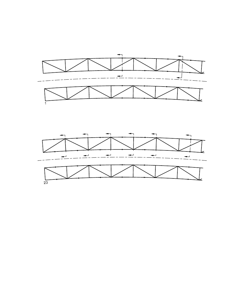
concrete in this example. For this check, the deck is assumed to be placed in four separate casts. All
casts are assumed to be made across the entire deck width. The first cast is in Span 1 from the
beginning of the span through member 13 in Girder 1 (refer to Appendix A and Figure 2 for the
location of the indicated members). The second cast is in Span 2 starting over member 23 through
member 38. The third cast is in Span 3 starting over member 48 to the end of the bridge. The fourth
cast is for the remaining sections over the piers. This sequence assures that uplift does not occur at
any time and that the girder stresses and deflections are within the prescribed limits in Article
6.10.3.2. Shorter casts over the piers would have led to uplift and larger moments in Span 1. Larger
top flange plates and perhaps a thicker web may have been required, as well as counter weights over
some supports, to prevent uplift.
The unfactored moments from the deck staging analysis are presented in Table C-1,
Appendix C. "Steel" identifies moments due to the steel weight based on the assumption that it was
placed at one time; "Deck" identifies moments due to the deck weight assumed to be placed on the
bridge at one time; "Cast" identifies the moments due to a particular deck cast; "SupImp" identifies
the moments due to the superimposed dead load placed on the fully composite bridge; and AFWS@
identifies the moments due to the future wearing surface placed on the fully composite bridge.
Included in the "Deck" and "Cast" moments are the moments due to the deck haunch and the stay-in-
place forms.
Reactions are accumulated sequentially in the staging analysis to check for uplift at each
stage. Accumulated deflections by stage are also computed. In each analysis of the deck placement,
prior casts are assumed to be composite. The modular ratio for the deck is assumed to be “3n” to
account for creep. A somewhat smaller modular ratio may be desirable for the staging analysis since
full creep usually takes approximately three years to occur. A modular ratio of “n” should be used to
check deck stresses since a smaller modular ratio results in higher stresses in the deck. Moments
and other actions determined from the deck-staging analysis are not considered for the strength limit
state checks.
Fatigue
The fatigue limit state is checked by using the stress ranges due to the passage of one fatigue
vehicle, defined in Article 3.6.1.4, traversing the length of the bridge in the critical transverse
position on the deck for each response. The load factor is 0.75 for the fatigue truck, as specified in

10
Table 3.4.1-1. The dynamic load allowance is 15 percent for the fatigue truck (Table 3.6.2.1-1).
Centrifugal force effects are included in this example. The transverse position of the truck may be
different for each response and for positive and negative values of the same response. The fatigue
truck is assumed to travel in either direction, or in opposite directions, to produce the maximum
stress range. Marked traffic lanes are not considered. This assumption provides larger fatigue
stresses than would be obtained if the fatigue truck were held to marked traffic lanes. The fatigue
truck is permitted to travel within two feet of the curb line. As specified in Article 6.6.1.2.1, stress
ranges are computed using the short-term composite section for both positive and negative bending
given that the deck slab longitudinal reinforcement specified in 6.10.1.7 are satisfied.
For points where the dead load produces compressive stress, Article 6.6.1.2.1 specifies that
twice the factored fatigue live load defined in Article 3.6.1.4, and factored according to the fatigue
load combination of Table 3.4.1-1, is to be used to determine if a net tensile stress is produced at the
point under consideration. The fatigue live load is placed in a single lane. If the dead load produces
tensile stress or, where dead load produces compressive stress, a net tensile stress occurs under dead
load combined with twice the factored fatigue load at a point, fatigue must be checked at that point
using the stress range produced by the single factored fatigue truck, whether or not the factored
fatigue truck by itself produces a net tensile stress.
Article 6.11.5 requires that longitudinal stress ranges due to warping and due to transverse
moments be considered when determining the sum of the stress ranges used in fatigue analysis. In
addition, the through-thickness bending stress range due to cross-sectional distortion at flange-to-
web fillet welds and at the termination of fillet welds connecting transverse elements must be
checked for fatigue. Computation of these through-thickness bending stresses is illustrated in the
Sample Calculations given in Appendix D.
Live Load Deflection
Article 2.5.2.6.2 provides optional deflection criteria that may be checked if required by the
bridge owner. Live load deflection is to be checked using the live load portion of Load Combination
Service I (Table 3.4.1-1) including the dynamic load allowance. The limiting live load deflection is
specified as the fraction of the span defined in Article 2.5.2.6.2. Different live load positions must
be examined for each girder and span since the deflections of curved girders usually differ
significantly at any one cross section. The uncracked composite section along the entire length of
the bridge should be used in computing the deflections. Centrifugal force effects are to be
considered. The multiple presence factors specified in Article 3.6.1.1.2 should be applied.
If a sidewalk were present, vehicular traffic would be constrained from a portion of the deck
(unless vehicles were permitted to mount the sidewalk), which would cause the computed live load
deflections to be reduced depending on which side of the bridge the sidewalk was placed. Sidewalk
load is discussed further in Article 3.6.1.6.

11
DESIGN
Section Properties
Table C-5, Appendix C, gives selected section properties for Girder 2. Locations from the
neutral axis to the top (T) and bottom (B) extreme fiber of the steel section are given. The section
properties include the longitudinal component of the top-flange bracing area. Longitudinal flange
stiffeners and the 1-inch bottom flange lips are also included in the section properties.
When the section is composite, the entire overhang, the concrete between the tub webs, and
half of the concrete between girders is considered effective, as specified in Article 4.5.2.2. The
haunch depth is considered in computing the section properties, but the area of the haunch is not
included. Since the actual depth of the haunch may vary from its theoretical value to account for
construction tolerances, many designers ignore the thickness of the haunch in all calculations. The
longitudinal reinforcing steel area equal to 20.0 square inches per box is assumed placed at the
neutral axis of the of the effective structural deck area. Considering that Article 6.10.1.7 requires
that two thirds of the deck longitudinal steel be placed in the top layer and that the deck top concrete
cover is thicker than the deck bottom concrete cover, the centroid of the deck reinforcement is
usually close to the assumed location. The longitudinal reinforcing steel within the effective portion
of the concrete deck is considered effective when the section is subjected to negative bending at the
strength limit state. The deck area is divided by “3n” and the reinforcing steel area is divided by 3
(for positive and negative bending, respectively) for computing the transformed section properties to
account for creep in the concrete for calculations involving the superimposed dead load. The
reinforcing steel area is adjusted since the concrete is assumed to transfer the force from the deck
steel to the rest of the cross section. This reduction in steel area is not applied by all designers and
may be ignored if it is not consistent with the practices of the owner agency.
Table D-1 in the Sample Calculations (Appendix D) also gives section properties for Girder
2 for the case where the bottom flange is composed of composite steel and concrete, as an alternative
to a conventional longitudinally stiffened bottom flange. The Sample Calculations in Appendix D
discuss the computation of the section properties given in Table D-1 in more detail.
Shear Connectors
Shear connectors are 7/8-inch diameter by 6 inches long.
The sum of the torsional and vertical bending shears is used with half of the girder to design
the shear connectors.
Flanges
The top flanges of the tubs must meet the criteria of Article 6.11.3.2 at the constructibility
limit state.
Two types of bottom (box) flanges are used in this example. In positive moment regions, the

12
bottom flange is an unstiffened plate. In the negative moment regions, a single longitudinal stiffener
is used to increase the compressive strength of the bottom flange. The critical stress for box flanges
is determined at the constructibility limit state.
Webs
In this example, transversely stiffened webs are used throughout. Transverse stiffener
designs are not shown, but are similar to the designs illustrated in the companion example of the I-
girder curved bridge. Transverse stiffeners are required throughout most of the girder length. The
spacing of the transverse stiffeners near the interior supports is 62 inches.
Diaphragms
Interior diaphragms at supports are solid plates with pairs of bearing stiffeners welded on
each side of an access hole. External diaphragms at supports are also solid plates.
Sample Calculations
Sample calculations at selected critical locations of Girder 2 are presented in Appendix D.
The calculations are intended to illustrate the application of some of the more significant provisions
of the Specifications. As such, complete calculations are not shown at all sections for each design.
The sample calculations illustrate calculations to be made at the Strength, Fatigue, Constructibility
and Serviceability limit states. The calculations also include longitudinal flange stiffener and
bearing stiffener designs, a top flange bracing member design, a diaphragm design, transverse
bending stress computations and a bolted field splice design. The calculations make use of the
moments, shears, torques, and top flange bracing forces contained in Tables C-1 through C-4 of
Appendix C and the section properties contained in Table C-5.
13
Deck concrete – f’
c
= 4,000 psi E = 3.6x10
6
psi
Haunch – 20 in. wide, 4 in. deep measured from top of web
Permanent deck forms are present
Total deck thickness = 9.5 in.
Figure 1. Box Girder Bridge Cross Section
14
23
24
20
19
16
15
12
11
8
7
6
5
4
3
2
10
14
18
22
21
17
13
9
R = 700 feet
Girder G2
Girder G1
2
11
2
*
*
*
*
1
49
50
46
45
44
43
40
39
36
35
32
31
28
27
24
42
48
47
41
R = 700 feet
Girder G2
Girder G1
Bearing Locations
*
*
*
*
*
Note: Sections 1-1, 2-2, etc. refer to the design
sections in Appendix C tables.
Section 9-9 is at the midspan of Span 2.
26
30
34
6
6
38
3
3
4
4
5
5
7
7
8
8
25
29
33
37
Figure 2. Node Numbers
15
0
0
0
0
6
1
-3
3
4
-3
-5
0
0
1
1
0
-2
-8
9
3
-5
6
0
0
3
2
-6
-8
21
16
19
-14
16
12
-11
-15
15
11
-13
-9
12
8
-9
-9
-9
-57
-43
-36
-44
11
4
-53
-29
-51
-49
-15
-28
2
-12
-48
-41
-32
-39
8
2
-43
-29
-44
-45
-14
-23
5
44
53
53
44
27
42
50
50
42
26
42
51
51
42
25
50
60
60
50
31
Figure 3. Case of Double-Diagonal Bracing: Lateral Flange Moments (k-ft) and Bracing Forces
(kips) Due to Entire Deck Weight with Overhang Brackets, Inclined Webs
16
Figure 4. Case of Single-Diagonal Bracing: Lateral Flange Moments (k-ft) and Bracing Forces
(kips) Due to Entire Deck Weight with Overhang Brackets, Inclined Webs
17
0
-5
11
-2
-5
12
15
-14
3
15
-15
2
0
12
-16
8
-20
6
4
0
-10
12
4
-12
-2
-5
12
-20
-23
28
22
-9
-4
23
18
-29
-34
20
15
-8
-4
24
18
-20
-47
-55
21
-100
60
-90
0
-37
25
14
47
-2
-47
21
-76
-33
17
11
-81
5
37
3
37
4
27
20
34
20
29
31
24
39
24
33
1
38
-1
38
1
0
-5
14
Figure 5. Case of Single-Diagonal Bracing: Lateral Flange Moments (k-ft) and Bracing Forces
(kips) Due to Cast #1 with Overhang Brackets, Inclined Webs

18
(This page is intentionally left blank.)

A-1
APPENDIX A
Girder Field Sections

A-2
(This page is intentionally left blank.)

A-3
June 21, 1997 9:25 AM
Bridge Type --> Box Girder Date Created -> 07/29/94
Project -----> Sample Box Design Initials -----> DHH
Project ID ---> BOX1SAMPLE
Description --> 160-210-160 spans 2-boxes
Number of girders ---> 2
Number of spans ---> 3
Project units ---> English
BRIDGE-SYSTEMsm 3D Version -> 2.1
Copyright (C) 1985, 1986, 1987, 1988, 1989, 1990
Bridge Software Development International, Ltd.
Box girder cross section
---center line of box ----
--to the top of the web -- width of
left side right side bottom flng
In In. In.
Girder 1 --> 60.00 60.00 81.00
Girder 2 --> 60.00 60.00 81.00

A-4
Girder --> 1 Field Section --> 1
Rght -----Top Flange---- ---Bottom Flange-- ---- Web ------
Mem. Node Length Width Thick. Fy Width Thick. Fy Depth Thick. Fy
Lip-> 1.00
1 3 15.74 16.00 1.0000 50. 81.00 .6250 50. 78.00 .5625 50.
2 5 15.74 16.00 1.0000 50. 81.00 .6250 50. 78.00 .5625 50.
3 7 15.74 16.00 1.0000 50. 81.00 .6250 50. 78.00 .5625 50.
4 9 7.87 16.00 1.0000 50. 81.00 .6250 50. 78.00 .5625 50.
5 11 7.87 16.00 1.0000 50. 81.00 .6250 50. 78.00 .5625 50.
6 13 7.87 16.00 1.0000 50. 81.00 .6250 50. 78.00 .5625 50.
7 15 7.87 16.00 1.0000 50. 81.00 .6250 50. 78.00 .5625 50.
8 17 7.87 16.00 1.0000 50. 81.00 .6250 50. 78.00 .5625 50.
9 19 7.87 16.00 1.0000 50. 81.00 .6250 50. 78.00 .5625 50.
Top Flange Bot Flange Web TOTAL Length
Section
Weight --> 10285. 16673. 29072. 56031. Ft.-> 94.46
Girder --> 1 Field Section --> 2
Rght -----Top Flange---- ---Bottom Flange-- ---- Web ------
Mem. Node Length Width Thick. Fy Width Thick. Fy Depth Thick. Fy
Lip-> 1.00
10 21 7.87 16.00 1.0000 50. 81.00 .6250 50. 78.00 .5625 50.
11 23 7.87 16.00 1.0000 50. 81.00 .6250 50. 78.00 .5625 50.
12 25 7.87 16.00 1.0000 50. 81.00 .6250 50. 78.00 .5625 50.
13 27 7.87 18.00 1.5000 50. 81.00 1.0000 50. 78.00 .5625 50.
14 29 7.87 18.00 1.5000 50. 81.00 1.0000 50. 78.00 .5625 50.
15 31 7.87 18.00 1.5000 50. 81.00 1.0000 50. 78.00 .5625 50.
16 33 7.87 18.00 3.0000 50. 81.00 1.5000 50. 78.00 .5625 50.
17 35 7.87 18.00 3.0000 50. 81.00 1.5000 50. 78.00 .5625 50.
Sup ---> 157.43
18 37 7.38 18.00 3.0000 50. 81.00 1.5000 50. 78.00 .5625 50.
19 39 7.38 18.00 3.0000 50. 81.00 1.5000 50. 78.00 .5625 50.
20 41 7.38 18.00 1.5000 50. 81.00 1.0000 50. 78.00 .5625 50.
21 43 7.38 18.00 1.5000 50. 81.00 1.0000 50. 78.00 .5625 50.
22 45 14.76 18.00 1.5000 50. 81.00 1.0000 50. 78.00 .5625 50.
Top Flange Bot Flange Web TOTAL Length
Section
Weight --> 23544. 32096. 33009. 88649. Ft.-> 107.25

A-5
Girder --> 1 Field Section --> 3
Rght -----Top Flange---- ---Bottom Flange-- ---- Web ------
Mem. Node Length Width Thick. Fy Width Thick. Fy Depth Thick. Fy
Lip-> 1.00
23 47 7.38 16.00 1.0000 50. 81.00 .7500 50. 78.00 .5625 50.
24 49 7.38 16.00 1.0000 50. 81.00 .7500 50. 78.00 .5625 50.
25 51 7.38 16.00 1.0000 50. 81.00 .7500 50. 78.00 .5625 50.
26 53 7.38 16.00 1.0000 50. 81.00 .7500 50. 78.00 .5625 50.
27 55 7.38 16.00 1.0000 50. 81.00 .7500 50. 78.00 .5625 50.
28 57 7.38 16.00 1.0000 50. 81.00 .7500 50. 78.00 .5625 50.
29 59 7.38 16.00 1.0000 50. 81.00 .7500 50. 78.00 .5625 50.
30 61 7.38 16.00 1.0000 50. 81.00 .7500 50. 78.00 .5625 50.
31 63 7.38 16.00 1.0000 50. 81.00 .7500 50. 78.00 .5625 50.
32 65 7.38 16.00 1.0000 50. 81.00 .7500 50. 78.00 .5625 50.
33 67 7.38 16.00 1.0000 50. 81.00 .7500 50. 78.00 .5625 50.
34 69 7.38 16.00 1.0000 50. 81.00 .7500 50. 78.00 .5625 50.
35 71 7.38 16.00 1.0000 50. 81.00 .7500 50. 78.00 .5625 50.
36 73 7.38 16.00 1.0000 50. 81.00 .7500 50. 78.00 .5625 50.
37 75 7.38 16.00 1.0000 50. 81.00 .7500 50. 78.00 .5625 50.
38 77 7.38 16.00 1.0000 50. 81.00 .7500 50. 78.00 .5625 50.
Top Flange Bot Flange Web TOTAL Length
Section
Weight --> 12857. 25010. 36340. 74207. Ft.-> 118.07
Girder --> 1 Field Section --> 4
Rght -----Top Flange---- ---Bottom Flange-- ---- Web ------
Mem. Node Length Width Thick. Fy Width Thick. Fy Depth Thick. Fy
Lip-> 1.00
39 79 14.76 18.00 1.5000 50. 81.00 1.0000 50. 78.00 .5625 50.
40 81 7.38 18.00 1.5000 50. 81.00 1.0000 50. 78.00 .5625 50.
41 83 7.38 18.00 1.5000 50. 81.00 1.0000 50. 78.00 .5625 50.
42 85 7.38 18.00 3.0000 50. 81.00 1.5000 50. 78.00 .5625 50.
43 87 7.38 18.00 3.0000 50. 81.00 1.5000 50. 78.00 .5625 50.
Sup ---> 206.63
44 89 7.87 18.00 3.0000 50. 81.00 1.5000 50. 78.00 .5625 50.
45 91 7.87 18.00 3.0000 50. 81.00 1.5000 50. 78.00 .5625 50.
46 93 7.87 18.00 1.5000 50. 81.00 1.0000 50. 78.00 .5625 50.
47 95 7.87 18.00 1.5000 50. 81.00 1.0000 50. 78.00 .5625 50.
48 97 7.87 18.00 1.5000 50. 81.00 1.0000 50. 78.00 .5625 50.
49 99 7.87 16.00 1.0000 50. 81.00 .6250 50. 78.00 .5625 50.
50 101 7.87 16.00 1.0000 50. 81.00 .6250 50. 78.00 .5625 50.
51 103 7.87 16.00 1.0000 50. 81.00 .6250 50. 78.00 .5625 50.
Top Flange Bot Flange Web TOTAL Length
Section
Weight --> 23544. 32097. 33009. 88650. Ft.-> 107.25

A-6
Girder --> 1 Field Section --> 5
Rght -----Top Flange---- ---Bottom Flange-- ---- Web ------
Mem. Node Length Width Thick. Fy Width Thick. Fy Depth Thick. Fy
Lip-> 1.00
52 105 7.87 16.00 1.0000 50. 81.00 .6250 50. 78.00 .5625 50.
53 107 7.87 16.00 1.0000 50. 81.00 .6250 50. 78.00 .5625 50.
54 109 7.87 16.00 1.0000 50. 81.00 .6250 50. 78.00 .5625 50.
55 111 7.87 16.00 1.0000 50. 81.00 .6250 50. 78.00 .5625 50.
56 113 7.87 16.00 1.0000 50. 81.00 .6250 50. 78.00 .5625 50.
57 115 7.87 16.00 1.0000 50. 81.00 .6250 50. 78.00 .5625 50.
58 117 15.74 16.00 1.0000 50. 81.00 .6250 50. 78.00 .5625 50.
59 119 15.74 16.00 1.0000 50. 81.00 .6250 50. 78.00 .5625 50.
60 121 15.74 16.00 1.0000 50. 81.00 .6250 50. 78.00 .5625 50.
Sup ---> 157.43
Top Flange Bot Flange Web TOTAL Length
Section
Weight --> 10285. 16674. 29072. 56031. Ft.-> 94.46
Girder
Weight --> 80515. 122550. 160504. 363569. Ft.-> 521.48
Girder --> 2 Field Section --> 1
Rght -----Top Flange---- ---Bottom Flange-- ---- Web ------
Mem. Node Length Width Thick. Fy Width Thick. Fy Depth Thick. Fy
Lip-> 1.00
61 4 16.26 16.00 1.0000 50. 81.00 .6250 50. 78.00 .5625 50.
62 6 16.26 16.00 1.0000 50. 81.00 .6250 50. 78.00 .5625 50.
63 8 16.26 16.00 1.0000 50. 81.00 .6250 50. 78.00 .5625 50.
64 10 8.13 16.00 1.0000 50. 81.00 .6250 50. 78.00 .5625 50.
65 12 8.13 16.00 1.0000 50. 81.00 .6250 50. 78.00 .5625 50.
66 14 8.13 16.00 1.0000 50. 81.00 .6250 50. 78.00 .5625 50.
67 16 8.13 16.00 1.0000 50. 81.00 .6250 50. 78.00 .5625 50.
68 18 8.13 16.00 1.0000 50. 81.00 .6250 50. 78.00 .5625 50.
69 20 8.13 16.00 1.0000 50. 81.00 .6250 50. 78.00 .5625 50.
Top Flange Bot Flange Web TOTAL Length
Section
Weight --> 10621. 17218. 30022. 57862. Ft.-> 97.54

A-7
Girder --> 2 Field Section --> 2
Rght -----Top Flange---- ---Bottom Flange-- ---- Web ------
Mem. Node Length Width Thick. Fy Width Thick. Fy Depth Thick. Fy
Lip-> 1.00
70 22 8.13 16.00 1.0000 50. 81.00 .6250 50. 78.00 .5625 50.
71 24 8.13 16.00 1.0000 50. 81.00 .6250 50. 78.00 .5625 50.
72 26 8.13 16.00 1.0000 50. 81.00 .6250 50. 78.00 .5625 50.
73 28 8.13 18.00 1.5000 50. 81.00 1.0000 50. 78.00 .5625 50.
74 30 8.13 18.00 1.5000 50. 81.00 1.0000 50. 78.00 .5625 50.
75 32 8.13 18.00 1.5000 50. 81.00 1.0000 50. 78.00 .5625 50.
76 34 8.13 18.00 3.0000 50. 81.00 1.5000 50. 78.00 .5625 50.
77 36 8.13 18.00 3.0000 50. 81.00 1.5000 50. 78.00 .5625 50.
Sup ---> 162.57
78 38 7.62 18.00 3.0000 50. 81.00 1.5000 50. 78.00 .5625 50.
79 40 7.62 18.00 3.0000 50. 81.00 1.5000 50. 78.00 .5625 50.
80 42 7.62 18.00 1.5000 50. 81.00 1.0000 50. 78.00 .5625 50.
81 44 7.62 18.00 1.5000 50. 81.00 1.0000 50. 78.00 .5625 50.
82 46 15.24 18.00 1.5000 50. 81.00 1.0000 50. 78.00 .5625 50.
Top Flange Bot Flange Web TOTAL Length
Section
Weight --> 24313. 33145. 34088. 91545. Ft.-> 110.75
Girder --> 2 Field Section --> 3
Rght -----Top Flange---- ---Bottom Flange-- ---- Web ------
Mem. Node Length Width Thick. Fy Width Thick. Fy Depth Thick. Fy
Lip-> 1.00
83 48 7.62 16.00 1.0000 50. 81.00 .7500 50. 78.00 .5625 50.
84 50 7.62 16.00 1.0000 50. 81.00 .7500 50. 78.00 .5625 50.
85 52 7.62 16.00 1.0000 50. 81.00 .7500 50. 78.00 .5625 50.
86 54 7.62 16.00 1.0000 50. 81.00 .7500 50. 78.00 .5625 50.
87 56 7.62 16.00 1.0000 50. 81.00 .7500 50. 78.00 .5625 50.
88 58 7.62 16.00 1.0000 50. 81.00 .7500 50. 78.00 .5625 50.
89 60 7.62 16.00 1.0000 50. 81.00 .7500 50. 78.00 .5625 50.
90 62 7.62 16.00 1.0000 50. 81.00 .7500 50. 78.00 .5625 50.
91 64 7.62 16.00 1.0000 50. 81.00 .7500 50. 78.00 .5625 50.
92 66 7.62 16.00 1.0000 50. 81.00 .7500 50. 78.00 .5625 50.
93 68 7.62 16.00 1.0000 50. 81.00 .7500 50. 78.00 .5625 50.
94 70 7.62 16.00 1.0000 50. 81.00 .7500 50. 78.00 .5625 50.
95 72 7.62 16.00 1.0000 50. 81.00 .7500 50. 78.00 .5625 50.
96 74 7.62 16.00 1.0000 50. 81.00 .7500 50. 78.00 .5625 50.
97 76 7.62 16.00 1.0000 50. 81.00 .7500 50. 78.00 .5625 50.
98 78 7.62 16.00 1.0000 50. 81.00 .7500 50. 78.00 .5625 50.
Top Flange Bot Flange Web TOTAL Length
Section
Weight --> 13277. 25827. 37528. 76632. Ft.-> 121.93

A-8
Girder --> 2 Field Section --> 4
Rght -----Top Flange---- ---Bottom Flange-- ---- Web ------
Mem. Node Length Width Thick. Fy Width Thick. Fy Depth Thick. Fy
Lip-> 1.00
99 80 15.24 18.00 1.5000 50. 81.00 1.0000 50. 78.00 .5625 50.
100 82 7.62 18.00 1.5000 50. 81.00 1.0000 50. 78.00 .5625 50.
101 84 7.62 18.00 1.5000 50. 81.00 1.0000 50. 78.00 .5625 50.
102 86 7.62 18.00 3.0000 50. 81.00 1.5000 50. 78.00 .5625 50.
103 88 7.62 18.00 3.0000 50. 81.00 1.5000 50. 78.00 .5625 50.
Sup ---> 213.38
104 90 8.13 18.00 3.0000 50. 81.00 1.5000 50. 78.00 .5625 50.
105 92 8.13 18.00 3.0000 50. 81.00 1.5000 50. 78.00 .5625 50.
106 94 8.13 18.00 1.5000 50. 81.00 1.0000 50. 78.00 .5625 50.
107 96 8.13 18.00 1.5000 50. 81.00 1.0000 50. 78.00 .5625 50.
108 98 8.13 18.00 1.5000 50. 81.00 1.0000 50. 78.00 .5625 50.
109 100 8.13 16.00 1.0000 50. 81.00 .6250 50. 78.00 .5625 50.
110 102 8.13 16.00 1.0000 50. 81.00 .6250 50. 78.00 .5625 50.
111 104 8.13 16.00 1.0000 50. 81.00 .6250 50. 78.00 .5625 50.
Top Flange Bot Flange Web TOTAL Length
Section
Weight --> 24313. 33145. 34088. 91546. Ft.-> 110.75
Girder --> 2 Field Section --> 5
Rght -----Top Flange---- ---Bottom Flange-- ---- Web ------
Mem. Node Length Width Thick. Fy Width Thick. Fy Depth Thick. Fy
Lip-> 1.00
112 106 8.13 16.00 1.0000 50. 81.00 .6250 50. 78.00 .5625 50.
113 108 8.13 16.00 1.0000 50. 81.00 .6250 50. 78.00 .5625 50.
114 110 8.13 16.00 1.0000 50. 81.00 .6250 50. 78.00 .5625 50.
115 112 8.13 16.00 1.0000 50. 81.00 .6250 50. 78.00 .5625 50.
116 114 8.13 16.00 1.0000 50. 81.00 .6250 50. 78.00 .5625 50.
117 116 8.13 16.00 1.0000 50. 81.00 .6250 50. 78.00 .5625 50.
118 118 16.26 16.00 1.0000 50. 81.00 .6250 50. 78.00 .5625 50.
119 120 16.26 16.00 1.0000 50. 81.00 .6250 50. 78.00 .5625 50.
120 122 16.26 16.00 1.0000 50. 81.00 .6250 50. 78.00 .5625 50.
Sup ---> 162.57
Top Flange Bot Flange Web TOTAL Length
Section
Weight --> 10621. 17218. 30022. 57862. Ft.-> 97.54
Girder
Weight --> 83145. 126554. 165747. 375446. Ft.-> 538.52
------------ S T R U C T U R E ------------
Top Flange Bot Flange Web TOTAL
Weight --> 163660. 249104. 326251. 739015.

B-1
APPENDIX B
Girder Moments, Shears, and Torques at Tenth-Points

B-2
(This page is intentionally left blank.)

B-3
STRENGTH -- HL-93 Plus Dynamic Load Allow., Multiple Presence, and Centrifugal Forces
April 5, 1997 10:51 AM
Revised November 16, 2001
Bridge Type --> Box Girder Date Created -> 07/29/94
Project -----> Sample Box Design Initials -----> DHH
Project ID ---> BOX1SAMPLE
Description --> 160-210-160 spans 2-boxes
Number of girders ---> 2
Number of spans ---> 3
Project units ---> English
BRIDGE-SYSTEMsm 3D Version -> 2.1
Copyright (C) 1985, 1986, 1987, 1988, 1989, 1990
Bridge Software Development International, Ltd.
Stage
Definition
Stg1 =
Load due to weight of structural steel including girders and internal cross
bracing and top flange diagonal bracing
Stg6
=
Load due to weight of concrete deck placed at one time
Stg7 = Load due to weight of parapets and wearing surface placed on composite
bridge
Special = LRFD HL-93 live load vehicle responses including the dynamic load
allowance

B-4
Girder -> 1 Span -> 1 Length -> 157.43
D E A D L O A D S
---- MOMENTS ---- ---- SHEARS ---- ----- TORQUES ----
Length Stg1 Stg6 Stg7 Stg1 Stg6 Stg7 Stg1 Stg6 Stg7
.00 0 0 0 27 114 58 42 286 -145
15.74 521 2191 790 19 80 27 82 398 -125
31.49 882 3666 1377 10 45 18 34 189 -93
47.23 1049 4321 1684 5 23 11 30 153 -92
62.97 1047 4320 1706 -6 -25 -7 -1 9 -54
78.71 851 3503 1441 -11 -44 -13 -29 -125 -30
94.46 493 2043 901 -16 -69 -19 -33 -158 0
110.20 -75 -315 83 -23 -98 -30 -54 -262 49
125.94 -837 -3461 -1010 -28 -116 -41 -25 -165 108
141.69 -1781 -7206 -2357 -34 -137 -56 -10 -135 193
157.43 -2969 -11629 -4097 -44 -171 -94 -22 -231 294
L I V E L O A D S
-------------------------- Moments -------------------------
--- Lane --- -- Truck -- -- Special-- 1-Lane Truck
Length POS NEG POS NEG POS NEG POS NEG
.00 0 0 0 0 0 0 0 0
15.74 0 0 505 -66 2472 -469 505 -66
31.49 0 0 845 -132 4330 -938 845 -132
47.23 0 0 997 -198 5412 -1408 997 -198
62.97 0 0 1043 -260 5863 -1878 1043 -260
78.71 0 0 1014 -318 5777 -2338 1014 -318
94.46 0 0 923 -373 5189 -2795 923 -373
110.20 0 0 748 -450 4109 -3915 748 -450
125.94 0 0 482 -549 2602 -4547 482 -549
141.69 0 0 182 -669 1252 -5559 182 -669
157.43 0 0 156 -843 1061 -7784 156 -843
----------------- Shears--------------------- -- Torque --
--- Lane --- -- Truck -- -- Special-- --Maximums--
Length POS NEG POS NEG POS NEG POS NEG
.00 0 0 35 -3 139 -24 660 -398
15.74 0 0 28 -4 115 -29 775 -448
31.49 0 0 23 -6 94 -35 756 -482
47.23 0 0 19 -8 78 -41 597 -389
62.97 0 0 15 -11 53 -52 389 -307
78.71 0 0 11 -15 40 -63 309 -354
94.46 0 0 9 -18 31 -83 360 -479
110.20 0 0 7 -23 25 -101 462 -636
125.94 0 0 5 -27 21 -116 569 -766
141.69 0 0 5 -29 19 -127 668 -866
157.43 0 0 3 -36 14 -163 1049 -922

B-5
Girder -> 1 Span -> 2 Length -> 206.63
D E A D L O A D S
---- MOMENTS ---- ---- SHEARS ---- ----- TORQUES ----
Length Stg1 Stg6 Stg7 Stg1 Stg6 Stg7 Stg1 Stg6 Stg7
.00 -2969 -11629 -4097 45 175 96 36 294 -335
20.66 -1422 -5845 -1864 31 128 54 4 105 -206
41.33 -326 -1516 -220 25 110 37 60 309 -120
61.99 493 1881 988 17 72 23 39 205 -52
82.65 977 3900 1705 11 47 11 61 261 -20
103.31 1118 4442 1944 0 0 0 0 0 0
123.98 976 3900 1705 -11 -47 -11 -64 -261 20
144.64 492 1880 986 -17 -72 -24 -39 -205 51
165.30 -327 -1519 -222 -25 -110 -37 -60 -309 120
185.96 -1422 -5848 -1867 -31 -127 -54 -4 -105 206
206.63 -2969 -11633 -4098 -45 -175 -96 -36 -294 334
L I V E L O A D S
-------------------------- Moments -------------------------
--- Lane --- -- Truck -- -- Special-- 1-Lane Truck
Length POS NEG POS NEG POS NEG POS NEG
.00 0 0 156 -843 1061 -7784 156 -843
20.66 0 0 245 -547 1310 -4411 245 -547
41.33 0 0 624 -417 2993 -3033 624 -417
61.99 0 0 894 -317 4784 -2275 894 -317
82.65 0 0 1050 -248 5926 -2008 1050 -248
103.31 0 0 1091 -188 6304 -1749 1091 -188
123.98 0 0 1050 -249 5928 -2013 1050 -249
144.64 0 0 895 -318 4775 -2279 895 -318
165.30 0 0 623 -416 3000 -3021 623 -416
185.96 0 0 257 -547 1315 -4421 257 -547
206.63 0 0 157 -830 1062 -7788 157 -830
----------------- Shears--------------------- -- Torque --
--- Lane --- -- Truck -- -- Special-- --Maximums--
Length POS NEG POS NEG POS NEG POS NEG
.00 0 0 39 -3 171 -15 1049 -922
20.66 0 0 30 -4 140 -23 995 -702
41.33 0 0 26 -5 124 -26 919 -598
61.99 0 0 21 -8 101 -37 716 -464
82.65 0 0 18 -10 78 -45 555 -383
103.31 0 0 15 -15 58 -57 446 -430
123.98 0 0 10 -18 43 -78 413 -540
144.64 0 0 8 -21 36 -101 500 -724
165.30 0 0 4 -26 26 -124 625 -906
185.96 0 0 4 -31 23 -140 713 -991
206.63 0 0 3 -37 14 -166 928 -1046

B-6
Girder -> 1 Span -> 3 Length -> 157.43
D E A D L O A D S
---- MOMENTS ---- ---- SHEARS ---- ----- TORQUES ----
Length Stg1 Stg6 Stg7 Stg1 Stg6 Stg7 Stg1 Stg6 Stg7
.00 -2969 -11633 -4098 44 171 94 22 231 -296
15.74 -1780 -7203 -2359 34 137 56 10 134 -194
31.49 -837 -3459 -1013 28 116 41 25 166 -109
47.23 -74 -312 80 23 98 30 54 262 -50
62.97 493 2044 897 16 69 19 33 158 -1
78.71 851 3504 1437 11 44 13 30 125 29
94.46 1047 4320 1703 6 25 7 1 -10 53
110.20 1048 4321 1681 -5 -23 -11 -30 -153 90
125.94 882 3666 1375 -10 -45 -18 -34 -190 91
141.69 521 2189 788 -19 -80 -28 -82 -398 132
157.43 0 0 0 -27 -114 -59 -42 -285 174
L I V E L O A D S
-------------------------- Moments -------------------------
--- Lane --- -- Truck -- -- Special-- 1-Lane Truck
Length POS NEG POS NEG POS NEG POS NEG
.00 0 0 157 -830 1062 -7788 157 -830
15.74 0 0 182 -673 1248 -5556 182 -673
31.49 0 0 482 -547 2591 -4532 482 -547
47.23 0 0 747 -449 4099 -3900 747 -449
62.97 0 0 923 -372 5181 -2783 923 -372
78.71 0 0 1014 -312 5769 -2328 1014 -312
94.46 0 0 1042 -255 5855 -1868 1042 -255
110.20 0 0 997 -193 5405 -1402 997 -193
125.94 0 0 845 -129 4326 -993 845 -129
141.69 0 0 505 -65 2470 -466 505 -65
157.43 0 0 0 0 0 0 0 0
----------------- Shears--------------------- -- Torque --
--- Lane --- -- Truck -- -- Special-- --Maximums--
Length POS NEG POS NEG POS NEG POS NEG
.00 0 0 38 -3 167 -15 928 -1046
15.74 0 0 29 -5 128 -19 874 -657
31.49 0 0 27 -5 116 -21 770 -549
47.23 0 0 23 -7 101 -25 640 -434
62.97 0 0 18 -9 83 -31 482 -319
78.71 0 0 15 -11 64 -38 375 -281
94.46 0 0 11 -15 51 -52 346 -378
110.20 0 0 8 -19 41 -77 434 -591
125.94 0 0 6 -23 32 -92 512 -751
141.69 0 0 4 -28 27 -113 503 -772
157.43 0 0 3 -35 24 -139 399 -662

B-7
Girder -> 2 Span -> 1 Length -> 162.57
D E A D L O A D S
---- MOMENTS ---- ---- SHEARS ---- ----- TORQUES ----
Length Stg1 Stg6 Stg7 Stg1 Stg6 Stg7 Stg1 Stg6 Stg7
.00 0 0 0 31 110 91 43 98 418
16.26 555 2268 816 19 74 39 87 276 323
32.51 938 3868 1418 11 44 26 35 92 241
48.77 1116 4632 1726 5 21 14 32 88 148
65.03 1115 4633 1733 -7 -26 -8 -2 -22 49
81.29 905 3780 1446 -11 -45 -14 -32 -129 -45
97.54 525 2207 867 -17 -69 -28 -36 -125 -134
113.80 -79 -256 -2 -24 -97 -40 -59 -203 -201
130.06 -892 -3579 -1166 -29 -117 -51 -28 -53 -247
146.31 -1896 -7599 -2610 -35 -137 -62 -10 63 -273
162.57 -3154 -12272 -4473 -46 -185 -96 -22 48 -346
L I V E L O A D S
-------------------------- Moments -------------------------
--- Lane --- -- Truck -- -- Special-- 1-Lane Truck
Length POS NEG POS NEG POS NEG POS NEG
.00 0 0 0 0 0 0 0 0
16.26 0 0 537 -64 2606 -484 537 -64
32.51 0 0 898 -129 4559 -967 898 -129
48.77 0 0 1056 -195 5687 -1446 1056 -195
65.03 0 0 1100 -263 6152 -1931 1100 -263
81.29 0 0 1066 -336 6059 -2416 1066 -336
97.54 0 0 963 -416 5434 -2907 963 -416
113.80 0 0 775 -511 4308 -4097 775 -511
130.06 0 0 506 -619 2751 -4768 506 -619
146.31 0 0 194 -749 1305 -5836 194 -749
162.57 0 0 173 -934 1114 -8127 173 -934
----------------- Shears--------------------- -- Torque --
--- Lane --- -- Truck -- -- Special-- --Maximums--
Length POS NEG POS NEG POS NEG POS NEG
.00 0 0 41 -8 128 -26 621 -533
16.26 0 0 35 -8 110 -29 774 -503
32.51 0 0 30 -8 93 -35 785 -469
48.77 0 0 24 -8 75 -44 638 -427
65.03 0 0 17 -12 54 -52 412 -391
81.29 0 0 12 -18 40 -67 348 -439
97.54 0 0 9 -23 36 -85 333 -535
113.80 0 0 8 -29 33 -102 433 -676
130.06 0 0 5 -33 26 -114 552 -793
146.31 0 0 3 -36 16 -127 687 -848
162.57 0 0 3 -41 13 -155 980 -863

B-8
Girder -> 2 Span -> 2 Length -> 213.38
D E A D L O A D S
---- MOMENTS ---- ---- SHEARS ---- ----- TORQUES ----
Length Stg1 Stg6 Stg7 Stg1 Stg6 Stg7 Stg1 Stg6 Stg7
.00 -3154 -12272 -4473 47 185 102 36 -33 447
21.34 -1513 -6169 -2107 32 130 65 3 -101 372
42.68 -348 -1473 -371 26 105 50 64 183 333
64.01 525 2077 893 17 69 35 40 118 243
85.35 1040 4196 1638 12 46 17 68 237 126
106.69 1190 4826 1890 0 0 0 0 0 0
128.03 1039 4195 1638 -12 -46 -17 -68 -237 -127
149.36 525 2075 893 -17 -69 -35 -40 -118 -243
170.70 -348 -1476 -370 -26 -105 -50 -64 -183 -335
192.04 -1514 -6173 -2106 -32 -130 -65 -3 102 -373
213.38 -3155 -12275 -4469 -47 -185 -102 -36 33 -448
L I V E L O A D S
-------------------------- Moments -------------------------
--- Lane --- -- Truck -- -- Special-- 1-Lane Truck
Length POS NEG POS NEG POS NEG POS NEG
.00 0 0 173 -934 1114 -8127 173 -934
21.34 0 0 262 -609 1401 -4629 262 -609
42.68 0 0 630 -467 3176 -3197 630 -467
64.01 0 0 908 -356 5018 -2366 908 -356
85.35 0 0 1071 -265 6205 -2070 1071 -265
106.69 0 0 1117 -187 6598 -1786 1117 -187
128.03 0 0 1070 -264 6204 -2065 1070 -264
149.36 0 0 907 -354 5001 -2355 907 -354
170.70 0 0 629 -466 3166 -3165 629 -466
192.04 0 0 269 -608 1393 -4627 269 -608
213.38 0 0 172 -930 1114 -8128 172 -930
----------------- Shears--------------------- -- Torque --
--- Lane --- -- Truck -- -- Special-- --Maximums--
Length POS NEG POS NEG POS NEG POS NEG
.00 0 0 44 -3 160 -14 980 -863
21.34 0 0 37 -3 135 -22 978 -709
42.68 0 0 33 -6 120 -33 925 -569
64.01 0 0 28 -9 100 -42 754 -433
85.35 0 0 22 -11 78 -46 580 -425
106.69 0 0 16 -16 57 -57 477 -491
128.03 0 0 11 -22 46 -78 391 -596
149.36 0 0 9 -28 41 -99 456 -746
170.70 0 0 6 -34 33 -120 603 -915
192.04 0 0 3 -37 22 -135 725 -974
213.38 0 0 3 -43 14 -159 878 -976

B-9
Girder -> 2 Span -> 3 Length -> 162.57
D E A D L O A D S
---- MOMENTS ---- ---- SHEARS ---- ----- TORQUES ----
Length Stg1 Stg6 Stg7 Stg1 Stg6 Stg7 Stg1 Stg6 Stg7
.00 -3155 -12275 -4469 46 185 96 22 -48 346
16.26 -1895 -7595 -2606 35 137 62 10 -63 273
32.51 -891 -3577 -1162 29 117 51 28 53 247
48.77 -79 -253 3 24 97 40 59 203 201
65.03 525 2208 871 17 69 28 36 125 134
81.29 906 3781 1450 11 45 14 32 129 45
97.54 1115 4634 1737 7 26 8 1 22 -49
113.80 1116 4632 1729 -5 -21 -14 -32 -88 -148
130.06 938 3867 1421 -11 -44 -26 -35 -92 -241
146.31 555 2266 816 -19 -74 -39 -87 -276 -323
162.57 0 0 0 -31 -110 -91 -43 -98 -417
L I V E L O A D S
-------------------------- Moments -------------------------
--- Lane --- -- Truck -- -- Special-- 1-Lane Truck
Length POS NEG POS NEG POS NEG POS NEG
.00 0 0 172 -930 1114 -8128 172 -930
16.26 0 0 195 -751 1312 -5843 195 -751
32.51 0 0 507 -623 2762 -4778 507 -623
48.77 0 0 777 -513 4320 -4106 777 -513
65.03 0 0 965 -419 5445 -2917 965 -419
81.29 0 0 1067 -334 6068 -2424 1067 -334
97.54 0 0 1101 -261 6160 -1936 1101 -261
113.80 0 0 1056 -194 5689 -1451 1056 -194
130.06 0 0 898 -128 4560 -971 898 -128
146.31 0 0 538 -64 2607 -487 538 -64
162.57 0 0 0 0 0 0 0 0
----------------- Shears--------------------- -- Torque --
--- Lane --- -- Truck -- -- Special-- --Maximums--
Length POS NEG POS NEG POS NEG POS NEG
.00 0 0 43 -3 158 -14 878 -976
16.26 0 0 36 -3 128 -15 853 -674
32.51 0 0 33 -5 115 -26 799 -536
48.77 0 0 28 -8 102 -33 685 -430
65.03 0 0 22 -9 85 -36 542 -321
81.29 0 0 18 -12 67 -40 415 -360
97.54 0 0 12 -17 52 -54 385 -440
113.80 0 0 8 -24 44 -75 433 -626
130.06 0 0 8 -30 34 -93 502 -782
146.31 0 0 8 -35 28 -111 533 -783
162.57 0 0 8 -41 26 -129 533 -621

B-10
(
This page is intentionally left blank.)

C-1
APPENDIX C
Selected Design Forces and Girder 2 Section Properties

C-2
(This page is intentionally left blank.)

C-3
Table C-1. Selected Unfactored Moments (k-ft) and Web Fatigue Shears (kips),
Girder 2
Section
Node
Steel
Deck
Cast(#)
1
SupImp
2
FWS
3
LLmax
4
Fat
min
5
Fat
max
5
1-1
10
1,144
4,747
2,979(1)
1,038(2)
765
1,006
5,920
-1,689
-239
V = -14k
1,258
V = 23k
2-2
20.3
Splice
462
1,941
2,749(1)
-647(2)
326
428
5,264
-3,087
-451
V = -26k
1,108
V = 12k
3-3
28
-892
-3,579
752(1)
-3,682(2)
-504
-663
2,751
-4,768
-649
V = -34
646
V = 8k
4-4
32
-1,896
-7,599
-317(1)
-5,305(2)
-1,127
-1,483
1,305
-5,836
-784
V = -36
258
V = 2k
5-5
36
-3,154
-12,272
-1,378(1)
-6,915(2)
-1,932
-2,541
1,114
-8,127
-961
V = -44k
173
V = 4k
6-6
40
-1,956
-7,866
-1,378(1)
-4,654(2)
-1,163
-1,530
1,049
-5,445
-656
V = -5k
192
V = 37k
7-7
44
-979
-4,015
-1,378(1)
-2,392(2)
-563
-740
2,132
-3,753
-542
V = -8k
554
V = 35k
8-8
48
184
634
-1,378(1)
922(2)
142
186
4,121
-2,525
-403
V = -11k
917
V = 32k
9-9
62
1,190
4,826
-1,378(1)
4,960(2)
816
1,074
6,598
-1,786
-182
V = -18k
1,271
V = 18K
1
(#) denotes Deck Cast number
Cast #1 begins at Section 1-1 and ends at Section 3-3 (similar for span 3)
Cast #2 begins at Section 8-8 and is symmetrical in the center span (includes Cast #1)
Steel, Deck and Cast moments are unfactored. Deck and Cast moments include the
moments due to the deck haunch and stay-in-place forms.
2
SupImp - Unfactored superimposed dead load
3
FWS - Unfactored future wearing surface dead load
4
LLmax - Unfactored live-load plus the dynamic load allowance moment due to multiple lanes of LRFD HL-93.
Dynamic load allowance is included according to Article 3.6.2.
5
Fat - Maximum and minimum fatigue moment due to one fatigue vehicle plus 15% dynamic load allowance times
the load factor of 0.75 specified in Table 3.4.1-1. Vertical shears in the critical web (V) due to the factored
fatigue vehicle are given in the “Fat” columns. Fatigue moments and shears are increased by 10 percent to
allow for warping.
All live load moments and shears, including fatigue moments and shears, include centrifugal force effects.
Multiple presence factors (Table 3.6.1.1.2-1) were considered in determining LLmax.
The location of nodes and sections may be found by referring to Figure 2 and Appendix A.

C-4
Table C-2. Shear (kips), Girder 2 Span 1 at Tenth-Points
Tenth
Point
Steel
Deck
SupImp
FWS
Total DL
LL + IM
Factored
Shear
0
31
110
39
52
232
128
527
1
19
74
17
22
132
110
363
2
11
44
11
15
81
93
268
3
5
21
6
8
40
75
183
4
-7
-26
-3
-5
-41
-52
-143
5
-11
-45
-6
-8
-70
-67
-207
6
-17
-69
-12
-16
-114
-85
-295
7
-24
-97
-17
-23
-161
-102
-385
8
-29
-117
-22
-29
-197
-114
-453
9
-35
-137
-27
-35
-234
-127
-524
10
-46/47
-185/185
-41/44
-55/58
-327/334
-155/160
-694/712
Live load shear of the same sign as the dead load shear is reported. Reported shears are vertical shears and are for
bending plus torsion in the critical web.

C-5
Table C-3. Selected Unfactored Torques (k-ft), Girder 2
Section
Node
Steel
Deck
SupImp
1
FWS
2
LL
max
3
Fat
min
4
Fat
max
4
1-1
10
59
205
464
5
41
54
525
-409
-85
174
2-2
20.3
Splice
-36
-125
-188
-58
-76
348
-556
-165
96
3-3
28
-28
-53
352
-107
-140
552
-793
-238
108
4-4
32
-10
63
-420
-118
-155
687
-848
-241
132
5-5
36
-22
36
48
-33
-149
193
-197
254
980
6
-863
-232
6
254
6
6-6
40
23
-52
-335
163
215
979
-753
-171
260
7-7
44
28
13
-305
145
191
955
-649
-105
264
8-8
48
72
211
-298
125
164
839
-501
-90
244
9-9
62
0
0
0
0
0
477
-491
-100
116
1
SupImp - Unfactored superimposed dead load
2
FWS - Unfactored future wearing surface dead load
3
LL
max
- Unfactored live-load plus dynamic load allowance torque due to multiple lanes of LRFD HL-93. Dynamic
load allowance is included according to Article 3.6.2.
4
Fat - Maximum and minimum torques due to one fatigue vehicle plus 15% dynamic load allowance times the
load factor of 0.75 specified in Table 3.4.1-1.
5
Bottom value, where listed, is the torque due to Cast #1.
6
Only the minimum and maximum live-load torques are reported at the pier section.
All live load torques, including fatigue torques, include centrifugal force effects. Multiple presence factors (Table
3.6.1.1.2-1) were considered in determining LL
MAX
.
The location of nodes and sections are shown in Figure 2 and Appendix A.

C-6
Table C-4. Top Flange Bracing Forces (kip), Girder 2 Span 1
Element
Steel
Deck
SupImp
FWS
LL+I
M
Fact
*Cast #1
Cast #2
Const
1
-13
-40
-3
-4
-2
-79
-100
7
-141
2
6
12
-2
-2
-3
12
60
0
83
3
-11
-39
-5
-6
-4
-85
-90
13
-126
4
-4
-20
-4
-5
-5
-51
0
7
-5
5
-2
-7
-4
-5
-5
-33
-37
18
-49
6
-10
-38
-4
-5
-4
-80
-55
15
-81
7
7
25
-1
-2
-4
29
25
23
69
8
-6
-15
-2
-2
-3
-37
-76
31
-103
9
11
31
3
3
3
66
70
15
120
10
9
46
3
3
3
82
-51
64
-53
11
7
42
2
3
2
72
71
-31
98
12
12
33
3
4
3
71
-25
82
86
13
-8
-16
-2
-3
-3
-42
43
-76
-51
Notes:
1. Casts consider overhang bracing forces
2. Fact = 1.0[1.25(DL) + 1.75(LL+IM)]
3. Const = 1.25[Steel + Cast #1]
or 1.25[Steel + Cast #1 + Cast #2]
*These values are taken from Figure 5

C-7
Table C-5. Selected Section Properties for Girder 2
Section
Node
Section
Size (in.)
Section
Type
Moment of
Inertia (in
4
)
Neutral
Axis B (in.)
Neutral
Axis T (in.)
Noncomp
185,187
36.83
42.80
Comp DL
354,925
55.35
24.27
1-1
10
2-2
20.3
2 - 16 x 1
2 - 78 x 0.5625
83 x 0.625
A = 181 in
2
CompLL
479,646
68.84
10.78
Noncomp
275,175
35.32
45.18
CompDL
475,329
51.05
29.45
CompDL Bars
292,858
36.72
43.78
CompLL
650,889
64.77
15.73
3-3
28
2 - 18 x 1.5
2 - 78 x 0.5625
83 x 1
LS WT 8 x 28.5
A = 243 in
2
CompLL Bars
325,531
39.30
41.20
Noncomp
438,966
38.81
43.69
CompDL
633,467
50.44
32.06
CompDL Bars
454,805
39.76
42.74
CompLL
836,080
62.50
20.00
5-5
36
2 - 18 x 3
2 - 78 x 0.5625
83 x 1.5
LS WT 8 x 28.5
A = 338 in
2
CompLL Bars
484,714
41.55
40.95
Legend:
B =
vertical distance from the neutral axis to the outermost edge of the bottom flange
T
=
vertical distance from the neutral axis to the outermost edge of the top flange
Noncomp
=
steel section only
Comp DL
=
steel section plus concrete deck transformed using modular ratio of 3n
Comp DL Bars
=
steel section plus longitudinal reinforcement area divided by 3
Comp LL
=
steel section plus concrete deck transformed using modular ratio of n
Comp LL Bars
=
steel section plus longitudinal reinforcement
LS
=
single longitudinal bottom flange stiffener
A =
total steel area of box section
Composite section properties, including the concrete deck, are computed using the structural deck area including the
overhang and half of the deck width between girders. The area of the deck haunch is not included. For composite
section properties including only the longitudinal reinforcement, a haunch depth is considered when determine the
position of the deck reinforcement relative to the steel girder. The longitudinal reinforcing steel area equal to 20.0 in
2
per
box is assumed placed at the neutral axis of the effective structural deck area.
The modular ratio, n, for live load is 7.56 and 3n is used for superimposed dead load. The effective area of reinforcing
steel used for superimposed dead load is adjusted for creep by a factor of 3. Thus, the reinforcing area used for the
superimposed dead load is 6.67 in
2
(20.0 in
2
/3).
The area and moment of inertia of the box section include the longitudinal component of the top flange bracing area, the
longitudinal flange stiffener (where present) and the 1-inch bottom flange lips. A single top-flange bracing member of
8.0 in
2
placed at an angle of 30 degrees from tangent to the girder is assumed. The vertical web depth is shown in the
above table. However, the total area of the inclined webs is used in computing all section properties.

C-8
(This page is intentionally left blank.)

D-1
APPENDIX D
Sample Calculations

D-2
(This page is intentionally left blank.)
Therefore, all section proportions for this location are satisfied. Section proportion checks for the other
design locations will not be shown. All subsequent sections satisfy these limits.
in. < 1.0 in. OK
1.1 0.5625
(
)
0.62
=
Eq (6.11.2.2-3)
t
f
1.1t
w
≥
in. < 16 in. OK
80.4
6
13.4
=
Eq (6.11.2.2-2)
b
f
D
6
≥
< 12 OK
16
2 1
( )
8
=
Eq (6.11.2.2-1)
b
f
2t
f
12.0
≤
Top flanges: 16 in. x 1.0 in.
Top flanges of tub sections subjected to compression and tension are proportioned such that:
Flange proportions (Article 6.11.2.2):
< 150 OK
80.4
0.5625
142.9
=
in.
78
4.123
4.0
80.4
=
D =
Determine the web depth along the incline. The web rise over run is 4:1.
Eq (6.11.2.1.2-1)
D
t
w
150
≤
For a web without longitudinal stiffeners, the web is proportioned such that:
Web proportions per Article 6.11.2.1:
The web and the flanges must be proportioned according to the provisions of Article 6.11.2.
Girder Stress Check Section 1-1 G2 Node 10
Girder Section Proportioning
D-3
9
43.09
80.4
2
31.3
=
=
9
D
c
D
2
where: k =
Eq (6.10.1.9.1-1)
but cannot exceed R
h
F
yc
or F
yw
/0.7
0.9Ek
D
t
w
2
F
crw
=
Compute the nominal bend-buckling stress for the transversely stiffened web without longitudinal
stiffeners.
The nominal bend-buckling resistance in girder webs for constructibility is determined according to the
provisions of Article 6.10.1.9.
Article C6.10.1.9.1 states that the compression flange stress may be used instead of the compression in
the web since the difference is negligible. This approach will be used in all subsequent web checks in this
example.
ksi (C)
4123 41.8
(
) 12
(
)
185187
−
1.25
(
)
13.96
−
=
f
cw
= f
top web
=
in. (inclined distance)
41.8
4.123
4.0
43.09
=
=
in. (vertical distance)
42.80
1.0
−
41.8
=
=
N.A. to top of top flange - top flange thickness
D
c
=
D = 80.4 in.
Compute the bending stress at the top of the web due to the above moment using the section properties
for the noncomposite section from Table C5.
Constructibility Load Factor = 1.25 according to the provisions of Article 3.4.2. Neglect the effects of
wind on the structure and the presence of construction equipment for this example.
Load
Moment
Steel
1,144 k-ft
Cast #1
2,979 k-ft
Total Moment
4,123 k-ft
In accordance with Article 6.11.1, the web bend-buckling provisions of Article 6.10.1.9 for the non-
composite section must be checked for steel weight and for the Cast #1 of the concrete deck. The web
bend-buckling check is not needed for the final condition. The unfactored moments are from Table C1 .
Girder Stress Check Section 1-1 G2 Node 10
Constructibility - Web
D-4

Girder Stress Check Section 1-1 G2 Node 10
Constructibility - Web (continued)
0.9 29000
(
) 31.3
(
)
80.4
0.5625
2
39.99
=
ksi < R
h
F
yc
= 1.0(50) = 50 ksi, therefore, F
crw
= 39.99 ksi
|-13.96| ksi <
φ
f
F
crw
= 1.0(39.99) = 39.99 ksi OK
D-5
Eq (C6.10.3.4-2)
k-ft
0.411 16.3
(
)
2
12
−
9.1
−
=
F
l
L
b
2
/ 12 =
M
l
=
Since the example girder is a tub box girder, the provisions of Article 6.10.3.2 are used. Compute the
lateral flange moment on the outermost tub flange due to the overhang forces. The lateral flange moment
at the brace points due to the overhang forces is negative in the top flange of G2 on the outside of the
curve because the stress due to the lateral moment is compressive on the convex side of the flange at
the brace points. The opposite would be true on the convex side of the G1 top flange on the inside of the
curve at the brace points, as illustrated in later calculations. The flange is treated as a continuous beam
supported at brace points; therefore, the unfactored lateral moment is calculated as follows:
k/ft
474
tan 49.1
2
π
360
1000
(
)
0.411
=
F
l
=
49.1 degrees
=
tan
1
−
78
67.5
α =
Compute the lateral force on the flanges due to overhang brackets. See Figure D-1.
Uniform load on brackets = 474 lbs/ft
Deck forms + Screed rail = 224 lbs/ft
lbs/ft
1
2
4
×
10
12
150
×
×
250
=
Deck:
Compute the vertical load on the overhang brackets.
The unbraced length of the top flange is approximately 16.3 feet in Span 1. Assume that the average
deck thickness in the overhang is 10 inches. The weight of the deck finishing machine is not considered.
The bracket loads are assumed to be applied uniformly although the brackets are actually spaced at
approximately 3 feet along the girder.
Since G2 is an outside girder, half of the overhang weight is assumed placed on the girder and the other
half is placed on the overhang brackets, as shown in Figure D-1.
Overhang Bracket Load
The flanges must be checked in flexure for steel weight and for Cast #1 of the concrete deck on the
noncomposite section according to the provisions of Article 6.11.3.2. The factored steel stresses during
the sequential placement of the concrete are not to exceed the nominal stresses. The effect of the
overhang brackets on the flanges must also be considered since G2 is an outside girder. The provisions
of Articles 6.10.3.2.1 through 6.10.3.2.3 are applied to the design of the top flange of tub box girders.
Girder Stress Check Section 1-1 G2 Node 10
Constructibility - Top Flange in Compression
D-6

f
l
is defined as the flange lateral bending stress determined using the provisions of Article 6.10.1.6 This
value may be determined directly from first-order elastic analysis in discretely braced compression
flanges if the following is satisfied.
k-ft (factored)
11.77
−
9.1
−
(
)
+
[
] 1.25
(
)
26.09
−
=
M
tot_lat
=
The lateral flange moment at the brace points due to curvature is negative when the top flanges are
subjected to compression because the stress due to the lateral moment is compressive on the convex
side of the flange at the brace points. The opposite is true whenever the top flanges are subjected to
tension.
Eq (C4.6.1.2.4b-1)
k-ft
2062 16.3
(
)
2
10 716.25
(
) 6.5
(
)
−
11.77
−
=
=
M
l
2
NRD
M
lat
=
The top flange size is constant between brace points in this region. In positive moment regions, the
largest value of f
bu
may not necessarily be at either brace point. Generally though, f
bu
will not be
significantly larger than the value at adjacent brace points, which is the case in this example. Therefore,
the computed value of f
bu
at Section 1-1 will be conservatively used in the strength check. The
approximate Eq (C4.6.1.2.4b-1) is used below to compute the lateral flange bending moment due to
curvature. Eq (C4.6.1.2.4b-1) assumes the presence of a cross frame at the point under investigation
and, as mentioned previously, M is constant over the distance between brace points. Although the use
of Eq (C4.6.1.2.4b-1) is not theoretically pure for tub girders or at locations in-between brace points, it
may conservatively be used. Note that the vertical web depth has been conservatively used in the
following calculation.
For a single flange, consider only half of the girder moment due to steel and Cast
#1. M = 4,123/2 = 2062 k-ft.
ksi (C)
4123 12
(
) 42.80
(
)
185187
−
1.25
(
)
14.29
−
=
f
top flg
= f
bu
=
From Table C1, the moment due to the steel weight plus Cast #1 is 4,123
k-ft. The load factor for
constructibility is 1.25 according to the provisions of Article 3.4.2. Using the section properties from
Table C5, the bending stress, f
bu
, in the top flange without consideration of longitudinal warping is
computed as:
In addition to the moment due to the overhang brackets, the inclined webs of the box cause a lateral
force on the top flanges. This force is relatively small in this case and will be ignored. A third source of
lateral bending is due to curvature, which can be conservatively estimated by the approximate V-load
Equation (C4.6.1.2.4b-1) given in the LRFD Specifications, as illustrated below.
Girder Stress Check Section 1-1 G2 Node 10
Constructibility - Top Flange in Compression (continued)
D-7
ksi (factored)
26.09
−
12
(
)
42.7
7.3
−
=
=
M
tot_lat
S
top_flange
f
l
=
in
3
1.0 16
(
)
2
6
42.7
=
S
top_flange
=
Therefore, the flange lateral bending stress, f
l
, may be determined from first-order elastic analysis.
ft.
1.2 7.57
(
)
1.0 1.0
(
)
14.29
−
50
16.99
=
L
b
= 16.3 ft. <
Check the relation given in Eq (6.10.1.6-2):
Article 6.10.1.10.2 indicates that the web load-shedding factor, R
b
, is taken as 1.0 for
constructibility.
Since the stresses remain reasonably constant over the section, C
b
is taken as 1.0.
in.
16
12 1
1
3
43.08 0.5625
(
)
16 1
( )
+
3.77
=
=
Eq (6.10.8.2.3-9)
b
fc
12 1
1
3
D
c
t
w
b
fc
t
fc
+
r
t
=
where:
Eq (6.10.8.2.3-4)
ft.
1.0 3.77
(
)
29000
50
12
7.57
=
=
1.0r
t
E
F
yc
L
p
=
where:
Eq (6.10.1.6-2)
L
b
1.2L
p
C
b
R
b
f
bu
F
yc
≤
Girder Stress Check Section 1-1 G2 Node 10
Constructibility - Top Flange in Compression (continued)
D-8

Eq (6.10.8.2.2-3)
16
2 1
( )
8
=
=
b
fc
2t
c
λ
f
=
Check if the slenderness ratio,
λ
f
, of the compression flange is less than or equal to
λ
pf
The local buckling resistance of the compression flange is computed as follows:
Article 6.10.3.2.1 directs the designer to the provisions of Article 6.10.8.2 for the determination of the
nominal flexural resistance, F
nc
, for the top flanges of tub box girders in compression. For constructibility,
the web load-shedding factor, R
b
, is taken as 1.0. The resistance is taken as the smaller of the local
buckling resistance determined as specified in Article 6.10.8.2.2 and the lateral torsional buckling
resistance determined using Article 6.10.8.2.3.
Eq (6.10.3.2.1-2)
f
bu
1
3
f
l
+
φ
f
F
nc
≤
Second, check the relation given by Eq (6.10.3.2.1-2).
|-14.29| + |-7.3| = 21.59 ksi < 1.0(1.0)(50) = 50 ksi OK
Therefore, checking the relation given by Eq (6.10.3.2.1-1) we obtain:
R
h
= 1.0 (Article 6.10.1.10.1)
φ
f
= 1.0 (Article 6.5.4.2)
where:
Eq (6.10.3.2.1-1)
f
bu
f
l
+
φ
f
R
h
F
yc
≤
First, check the relation given by Eq (6.10.3.2.1-1).
For critical stages of construction, the resistance of the compression flange in noncomposite boxes with
a single web (including tub flanges) at the constructibility limit state is to be computed according to the
criteria given in Article 6.10.3.2. The resistance of a flange and the approximate V-load Eq
(C4.6.1.2.4b-1) both assume that the lateral bending is equal at each end of a panel. As can be seen
from an examination of Figures 3 through 5 in the introduction section, this is obviously not the case.
Check the three relations given for discretely braced compression flanges in Article 6.10.3.2.1
Another significant source of lateral flange bending not considered in this calculation is the forces that
develop in single-diagonal top flange bracing members (arranged in the pattern shown in Figure 2 of the
introduction section) as a result of vertical bending of the box girder. This effect is recognized in lateral
flange moments taken directly from a finite element analysis, but a closed-form solution is more elusive.
As mentioned previously, this effect can probably be minimized most effectively by utilizing parallel
single-diagonal bracing members in each bay.
Girder Stress Check Section 1-1 G2 Node 10
Constructibility - Top Flange in Compression (continued)
D-9
in. < L
b
= 195.6 in.
Determine if the unbraced length, L
b
, is greater than or less than L
r
.
L
r
=
πr
t
E
F
yr
=
π 3.77
(
)
29000
0.7 50
(
)
341
=
in.
Eq (6.10.8.2.3-5)
L
p
< L
b
< L
r
, therefore, use Eq (6.10.8.2.3-2) for the lateral torsional buckling resistance.
F
nc
= C
b
1
1
F
yr
R
h
F
yc
−
L
b
L
p
−
L
r
L
p
−
−
R
b
R
h
F
yc
R
b
R
h
F
yc
≤
Eq (6.10.8.2.3-2)
where:
C
b
= for members where f
mid
/f
2
> 1 or f
2
= 0, this value is taken
as 1.0.
Eq (6.10.8.2.3-6)
f
mid
= 14.29 ksi (calculated above)
f
2
= largest compressive stress without consideration of lateral bending at either end
of the unbraced length of the flange under consideration.
The largest compressive stress in the top flange occurs at Node 12 of the 3D model,
approximately 65.04 ft. into span 1.
Girder Stress Check Section 1-1 G2 Node 10
Constructibility - Top Flange in Compression (continued)
λ
pf
=
0.38
E
F
yc
=
0.38
29000
50
9.15
=
Eq (6.10.8.2.2-4)
Since
λ
f
<
λ
pf
, the nominal flexural resistance is taken as F
nc
= R
b
R
h
F
yc
Since R
b
is taken as 1.0 for constructibility, F
nc
is equal to 50 ksi for the local buckling resistance.
The lateral torsional buckling resistance of the compression flange is computed as follows:
Determine if the unbraced length, L
b
, is greater than or less than L
p
.
L
b
= 16.3 12
(
)
195.6
=
in.
L
p
= 1.0r
t
E
F
yc
= 7.57 ft. (calculated previously)
Eq (6.10.8.2.3-4)
L
p
= 7.57 12
(
)
91
=
D-10
ksi < 1.0(1.0)(50) = 50 ksi
1.09 1
1
0.7 50
(
)
1.0 50
(
)
−
195.6
91
−
341
91
−
−
1.0
(
) 1.0
(
) 50
(
)
47.7
=
F
nc
=
Therefore, the lateral torsional buckling resistance is:
1.75
1.05
12.84
15.52
−
0.3
12.84
15.52
2
+
1.09
=
C
b
=
ksi
3704 12
(
) 42.8
(
)
185187
1.25
(
)
12.84
=
f
1
=
Load
Moment
Source
Steel
1,116 k-ft
Appendix B
Cast #1
2,588 k-ft
From separate calculations
Total unfactored moment 3,704 k-ft
f
1
occurs at Node 8 of the 3D model, approximately 48.78 ft. into span 1.
f
1
= stress without consideration of lateral bending at the brace point opposite to the
one corresponding to f
2
.
Eq (6.10.8.2.3-7)
1.75
1.05
f
1
f
2
−
0.3
f
1
f
2
2
+
2.3
≤
C
b
=
< 1.0 therefore, C
b
is calculated using Eq (6.10.8.2.3-7)
14.29
15.52
0.92
=
f
mid
/f
2
=
ksi
4476 12
(
) 42.8
(
)
185187
1.25
(
)
15.52
=
f
2
=
Load
Moment
Source
Steel
1,115 k-ft
Appendix B
Cast #1
3,361 k-ft
From separate calculations
Total unfactored moment 4,476 k-ft
Girder Stress Check Section 1-1 G2 Node 10
Constructibility - Top Flange in Compression (continued)
D-11

Girder Stress Check Section 1-1 G2 Node 10
Constructibility - Top Flange in Compression (continued)
Therefore, the nominal flexural resistance, F
nc
, of the compression flange is 47.7 ksi.
f
bu
1
3
f
l
+
φ
f
F
nc
≤
Eq (6.10.3.2.1-2)
|-14.29| + 1/3(|-7.3|) = 16.72 ksi < 1.0(47.7) = 47.7 ksi OK
Both flange requirements of Article 6.10.3.2.1 for discretely braced flanges in compression are satisfied.
The third requirement which involves the web bend-buckling resistance, Eq (6.10.3.2.1-3), was already
satisfied on page D-5 for this section.
D-12

= F
yc
b
c
t
c
= 50
83
2
0.625
(
)
1297
=
kips
P
w
= force in the web
= F
yw
Dt
w
=
50 80.4
(
) 0.5625
(
)
2261
=
kips (D is meaured along the incline)
Check if Case I, plastic neutral axis is in the web:
P
t
P
w
+
P
c
P
s
+
P
rb
+
P
rt
+
≥
800
2261
+
3061
=
<
1297
3521
+
4818
=
PNA not in the web
Check if Case II, plastic neutral axis is in the top flange:
P
t
P
w
+
P
c
+
P
s
P
rb
+
P
rt
+
≥
800
2261
+
1297
+
4358
=
>
3521
PNA is in the top flange
Girder Stress Check Section 1-1 G2 Node 10
Strength - Ductility Requirement
According to Article 6.11.6.2.2 for sections in positive flexure, the ductility requirements of Article 6.10.7.3
must be satisfied for compact and noncompact sections inorder to protect the deck from premature
crushing. The total depth of the composite section, D
t
, is calculated neglecting the haunch thickness and
using the structural thickness of the deck. All other field sections are checked similarly (not shown).
D
p
0.42D
t
≤
Eq (6.10.7.3-1)
where:
D
p
= distance from the top of the concrete deck to the neutral axis of the composite
section at the plastic moment, in.
This value can be calculated by solving for the depth of the web in compression at the
plastic moment, D
cp
, according to Table D6.1-1 of Appendix D, and adding the structural
thickness of the deck plus the top flange thickness (Case I) or adding only the structural
thickness (Case II).
First, determine if the plastic neutral axis is in the web, top flange, or deck. Neglect the
affect of the deck steel.
P
s
= force in the slab
= 0.85f
c
'b
s
t
s
= 0.85 4
( ) 109
(
) 9.5
(
)
3521
=
kips
(the effective width, b
s
, is taken
from separate calculations per
Article 4.6.2.6.1)
P
t
= force in the compression flange
= F
yt
b
t
t
t
= 50 16
(
) 1.0
(
)
800
=
kips
P
c
= force in the tension flange
D-13

Girder Stress Check Section 1-1 G2 Node 10
Strength - Ductility Requirement (continued)
Therefore, the following expression from Table D6.1-1 is used for determining the location
of the plastic neutral axis measured from the top of the top flange.
Y
bar
=
t
c
2
P
w
P
t
+
P
s
−
P
rt
−
P
rb
−
P
c
1
+
=
1
2
2261
800
+
3521
−
0
−
0
−
1297
1
+
0.3
=
in.
Therefore,
D
p
= 0.3
9.5
+
9.8
=
in. < 0.42D
t
= 0.42 0.625
80.4
+
1
+
9.5
+
(
)
38.4
=
in. OK
D-14
15.03 + 6.16 = 21.19 ksi < 1.0(1.0)(50) = 50 ksi OK
Therefore,
ksi (factored)
83.2 12
(
)
162
6.16
=
=
M
tot_lat
S
top_flange
f
l
=
in
3
18
2
3
( )
6
162
=
S
top_flange
=
k-ft (factored)
57.46
9.1
−
(
)
+
[
] 1.25
(
)
83.2
=
M
tot_lat
=
M
l
= -9.1 k-ft
Assume the overhang bracket loading is applied to the top flange as well.
k-ft
10069
−
16.3
(
)
2
10 716.25
(
) 6.5
(
)
−
57.46
=
=
M
l
2
NRD
M
lat
=
Determine the tensile flange lateral bending stress, f
l
, as specified in Article 6.10.1.6. A summary of this
calculation is shown here, refer to Section 1-1 computations for the expanded version.
ksi (T)
10069
−
12
(
) 43.69
(
)
438966
−
1.25
(
)
15.03
=
f
bu
=
Determine the factored tensile flange stress, f
bu
, calculated without consideration of flange lateral bending
for the top flanges of tub box girders.
Load
Moment
Steel
-3,154 k-ft
Cast #2
-6,915 k-ft
Total unfactored moment -10,069 k-ft
The noncomposite section must be checked for steel weight and for the maximum deck cast loading
(Cast #2) of the concrete deck for the section in the negative bending region. The unfactored moments
are from Table C1.
Eq (6.10.3.2.2-1)
f
bu
f
l
+
φ
f
R
h
F
yt
≤
For critical stages of construction, the following requirement must be met for tension in the top flange of a
tub girder. It is assumed that the flange is not continuously braced for constructibility.
Girder Stress Check Section 5-5 G2 Node 36
Constructibility - Top Flange in Tension
D-15
|-13.2| + |-0.74| = 13.94 ksi < 1.0(1.0)(50) = 50 ksi OK
f
bu
f
l
+
φ
f
R
h
F
yc
≤
Therefore, check Eq (6.10.3.2.1-1)
ksi
2.1
−
12
(
)
42.7
1.25
(
)
0.74
−
=
=
M
lat_tot
S
top_flange
f
l
=
Compute the total factored lateral flange bending stress, f
l
. From separate calculations, a first-order
elastic analysis can be used to compute the flange lateral bending stress. The cross-section, and its
associated properties, at this location for girder G1 are the same as previously calculated for girder G2.
k-ft
10.56
−
8.44
+
2.1
−
=
M
lat_tot
=
Therefore, the total unfactored lateral moment is:
k-ft
0.411 15.7
(
)
2
12
8.44
=
M
l
=
Compute the lateral flange moment due to the overhang bracket load.
Eq (C4.6.1.2.4b-1)
k-ft (C)
1904 15.7
(
)
2
10 683.75
(
) 6.5
(
)
−
10.56
−
=
=
M
l
2
NRD
M
lat
=
Unbraced length of flange = 15.7 ft.
M = 3,807/2 = 1,904 k-ft
Compute the lateral flange bending moment due to curvature using Eq (C4.6.1.2.4b-1). For a single
flange, consider only half of the girder moment due to Steel plus Cast #1 according to Article C6.11.3.2.
Load
Moment
Steel
1,075 k-ft
(Unfactored results are shown)
Cast #1
2,732 k-ft
Total moment
3,807 k-ft
Compute the bending moment in the box. Moment values used below are not tabulated.
The load on the overhang bracket produces a lateral flange moment at the brace points on the convex
side of the G1 inner top flange of the opposite sense from that on the convex side of the G2 outer top
flange. Therefore, check the constructibility stress in the G1 top flange on the inside of the curve at this
section. The basis of the following calculations is similiar to the girder G2 check.
Girder Stress Check Section 1-1 G1 Node 9
Constructibility - Top Flange in Compression
D-16

|-13.2| ksi < 1.0(39.99) = 39.99 ksi OK
f
bu
φ
f
F
crw
≤
Lastly, check the web bend-buckling given by Eq (6.10.3.2.1-3). The nominal web bend-buckling
resistance, F
crw
, was calculated previously for girder G2 and is the same for this location.
|-13.2| + 1/3(|-0.74|) = 13.45 ksi < 1.0(44.2) = 44.2 ksi OK
f
bu
1
3
f
l
+
φ
f
F
nc
≤
Therefore, the nominal flexural resistance, F
nc
, of the compression flange is 44.2 ksi.
ksi < 1.0(1.0)(50) = 50 ksi
1.0 1
1
0.7 50
(
)
1.0 50
(
)
−
188
91
−
341
91
−
−
1.0
(
) 1.0
(
) 50
(
)
44.2
=
F
nc
=
Assume C
b
= 1.0 for this girder for this example, a detailed calculation for C
b
is given for girder G2
L
p
< L
b
< L
r
, therefore, use Eq (6.10.8.2.3-2) for the lateral torsional buckling resistance.
L
r
= 341 in.
L
p
= 91 in.
in.
15.7 12
(
)
188
=
L
b
=
The lateral torsional buckling resistance of the compression flange is computed as follows:
F
nc
= R
b
R
h
F
yc
= 1.0(1.0)(50) = 50 ksi
λ
pf
= 9.15
λ
f
= 8
From previous calculations:
The local buckling resistance of the compression flange is computed as follows:
Determine the nominal flexural resistance for compression flanges of tub box girders according to Article
6.10.3.2.1.
Eq (6.10.3.2.1-2)
f
bu
1
3
f
l
+
φ
f
F
nc
≤
Check the second constructibility requirement according to Article 6.10.3.2.1.
Girder Stress Check Section 1-1 G1 Node 9
Constructibility - Top Flange in Compression (continued)
D-17

Girder Stress Check Section 1-1 G1 Node 9
Constructibility - Top Flange in Tension
The constructibility check for the top flange in tension may be conducted using the same procedure given
for girder G2 at Section 5-5.
D-18

Girder Stress Check Section 1-1 G2 Node 10
Fatigue - Bottom Flange
Check the fatigue stress in the bottom flange at this section according to the provisions of Articles
3.6.1.4 and 6.11.5. The fatigue design life is 75 years.
Base metal at transverse stiffener weld terminations and at stiffener-connection plate welds at locations
subject to a net tensile stress must be checked for Category C' (refer to Table 6.6.1.2.3-1). It is
assumed that stiffener-connection plates are fillet welded to the bottom flange. Thus, the base metal at
the top of the bottom flange adjacent to the weld must be checked for Category C'. It is further assumed
that the 75-year ADTT in a single lane will exceed the value of 745 trucks/day for a Category C' detail
above which the fatigue resistance is governed by the constant-amplitude fatigue threshold (refer to Table
C6.6.1.2.5-1).
One factored fatigue vehicle is to be placed at critical locations on the deck per the AASHTO-LRFD
fatigue provisions. According to Table 3.6.2.1-1, the dynamic load allowance is 0.15. Centrifugal force
effects are not included in this example, but should be considered by the designer. One-half of the
fatigue threshold is specified as the limiting stress range for this case since it is assumed that at some
time in the life of the bridge, a truck loading of twice the magnitude of the factored fatigue truck will occur.
By using half of the fatigue threshold, twice the factored truck is actually considered. According to the
provisions of Article 6.6.1.2.1, uncracked concrete section properties are to be used for fatigue checks.
As specified in Article 6.11.5, the stress range due to longitudinal warping is considered in checking the
fatigue resistance of the base metal at all details on the box section (6.6.1). The transverse bending
stress range is considered separately in evaluating the the fatigue resistance fo the base metal adjacent
to flange-to-web fillet welds and adjacent to the termination of fillet welds connecting transverse elements
to webs and box flanges. In this example, the fatigue moments have been increased by 10 percent to
allow for warping.
Moment
M
min
-239 k-ft
Table C1 (factored)
M
max
1,258 k-ft
Table C1 (factored)
M
range
1,497 k-ft
According to Article 6.6.1.2, the limiting stress range for Category C' = 6 ksi for the case where the
fatigue resistance is governed by the constant-amplitude fatigue threshold. The value of 6 ksi is equal to
one-half of the fatigue threshold of 12 ksi specified for a Category C' detail in Table 6.6.1.2.5-3.
Compute the range of vertical bending stress at the top of the bottom flange (section properties are taken
from Table C5):
f
range
=
1497 68.84
0.625
−
(
)
479646
12
(
)
2.55
=
ksi
f
range
<
φF
n
2.55 ksi < 6.0 ksi OK
D-19

in.
11.25 12
(
)
135
=
The average spacing of adjacent beams:
<- controls
in.
12 9.5
(
)
0.5 16
(
)
+
122
=
or
in.
12 9.5
(
)
0.5625
+
115
=
12.0t
s
+ the greater of t
w
or 1/2b
f
:
in.
0.25 112.4
(
) 12
(
)
337
=
One-quarter of the effective span length:
The effective width of the interior beam is the lesser of:
According to the provisions of Article 4.5.2.2, the entire deck cross sectional area is assumed to be
effective. The structural deck thickness, t
s
, is 9.5 in. The modular ratio, n, is 7.56. Calculate the
effective width according to Article 4.6.2.6.1. For open boxes, the effective flange width of each web
should be determined as though each web was an individual supporting element.
From Table C1, the bending plus torsional shear range due to one factored fatigue truck =
23 + (-14) = 37 kips. The shear values in Table C1 are vertical shears and are for the critical
web, which is subject to additive bending and torsional shears. The values have been increased
by 10 percent to account for warping.
Girder Stress Check Section 1-1 G2 Node 10
Fatigue - Shear Connectors
The shear connectors are designed according to the provisions of Article 6.11.10 which refers to Article
6.10.10.
The longitudinal fatigue shear range per unit length, V
fat
, for one top flange of a tub girder must be
computed for the web subjected to additive flexural and torsionial shears.
Determine the required pitch, p, of the shear connectors for fatigue at this section according to the
provisions of Article 6.10.10.1.2. The pitch, p, of the shear connectors must satisfy the following:
p
n Z
r
V
sr
≤
Eq (6.10.10.1.2-1)
The fatigue threshold for one stud shear connector in kips, Z
r
, is defined in Article 6.10.10.2 as follows:
Z
r
=
αd
2
5.5d
2
2
≥
Since a value for (ADTT)
SL
is needed for the calculation of
α, for purposes of this example this
value has not been calculated. When traffic data is available, check
αd
2
.
Use: 3 - 6 in. x 7/8 in. dia. studs/row.
Fatigue threshold for one 7/8 in. dia. shear stud =
5.5
2
0.875
(
)
2
2.105
=
kips.
Fatigue threshold for 3 such connectors/row = nZ
r
= 3 2.105
(
)
6.315
=
kips/row.
D-20

Moment arm of the deck = Neutral axis - t
flg
+ haunch + t
s
/2
Moment arm = 10.78
1.0
−
4.0
+
9.5
2
+
18.53
=
in
2
The horizontal fatigue shear range per unit length, V
sr
, is determined as the vector sum of the longitudinal
fatigue shear range, V
fat
, given by Eq (6.10.10.1.2-3) and the torsional fatigue shear range in the concrete
deck.
Compute the longitudinal fatigue shear range, V
fat
, for one top flange of the tub girder. Use one-half
of the moment of inertia.
Q = 137 18.53
(
)
2539
=
in
3
V
fat
=
VQ
I
=
37 2539
(
)
0.5 479646
(
)
0.39
=
k/in.
Eq (6.10.10.1.2-3)
The torsional fatigue shear range in the concrete deck is computed as:
T
fat
=
85
−
174
+
259
=
k-ft
(Table C3)
Compute the enclosed area within the composite box section including the midheight of the deck.
A
o
=
120
83
2 1
( )
−
[
]
+
[
]
2
0.625
2
78
+
1
+
9.5
2
+
1
144
59
=
ft
2
Girder Stress Check Section 1-1 G2 Node 10
Fatigue - Shear Connectors (continued)
The effective width of the exterior beam is taken as on-half the effective width of the interior beam plus the
lesser of:
One-eighth of the effective span length:
0.125 112.4
(
) 12
(
)
169
=
in.
6.0t
s
+ the greater of t
w
or 1/4b
f
:
6 9.5
(
)
0.5625
+
58
=
in.
or 6 9.5
(
)
0.25 16
(
)
+
61
=
in.
The width of the overhang:
4.0 12
(
)
48
=
in.
<- controls
Transformed deck area =
Area
n
=
122
2
48
+
9.5
(
)
7.56
137
=
in
2
Compute the first moment of the deck with respect to the neutral axis of the uncracked live load
composite section.
Determine the distance from the center of the deck to the neutral axis.
Section properties are from Table C5.
Neutral axis of the section is 10.78 in. from the top of the steel.
D-21
Although not illustrated here, the number of shear connectors that is provided must also be checked at
the strength limit state according to the provisions of Article 6.11.10 and subsequently Article 6.10.10.4.
in./row
6.315
0.43
14.7
=
=
nZ
r
V
sr
Shear stud pitch =
Compute the required shear connector pitch for fatigue for 3 studs per row.
0.39
(
)
2
0.18
(
)
2
+
0.43
=
=
V
fat
( )
2
F
fat
( )
2
+
V
sr
=
Therefore,
k/in.
259
2 59
(
) 12
(
)
0.18
=
=
T
2A
o
F
fat
=
Girder Stress Check Section 1-1 G2 Node 10
Fatigue - Shear Connectors (continued)
D-22
ksi
2224.25 12
(
)
2 55
(
) 144 1.0
(
)
1.69
=
=
T
2A
o
t
fc
f
v
=
ft
2
120
83
2 1
( )
−
[
]
+
[
]
2
0.75
2
78
+
1
2
+
1
144
55
=
A
o
=
Section Properties at Section 8-8
Top flange:
16 in. x 1.0 in.
(compression flange)
Web:
78 in. x 0.5625 in.
Bottom flange: 83 in. x 0.75 in.
Load
Torque (k-ft)
Steel
1.25(72)
= 90.0
(Table C3)
Deck
1.25(211)
= 263.75
SupImp
1.25(125)
= 156.25
FWS
1.5(164)
= 246.0
LL + IM
1.75(839)
= 1468.25
Total factored torque
= 2224.25 k-ft
where:
Eq (6.11.8.2.2-8)
0.57
1
2
∆
∆
2
4
f
v
F
yc
2
k
k
s
2
+
+
=
R
1
= limiting slenderness ratio for the box flange determined using Eq 6.11.8.2.2-8.
k = 4.0 according to Article 6.11.8.2 for the plate-buckling coefficient for uniform normal
stress
where:
Eq (6.11.10-1)
s
t
t
f
F
yf
k E
R
1
≤
Check the maximum transverse spacing, s
t
, between shear connectors on composite box flanges using
Eq 6.11.10-1. This limit insures that local buckling of the flange is prevented when it is subject to
compression. In positive bending regions, the maximum torque occurs at Section 8-8, therefore, the
maximum transverse shear connector spacing is determined at this location.
Girder Stress Check Section 8-8 G2 Node 48
Shear Connectors - Maximum Transverse Spacing
D-23
Girder Stress Check Section 8-8 G2 Node 48
Shear Connectors - Maximum Transverse Spacing (continued)
∆ =
1
3
f
v
F
yc
2
−
=
1
3
1.69
50
2
−
0.998
=
Eq (6.11.8.2.2-5)
Therefore,
R
1
=
0.57
1
2
0.998
0.998
2
4
1.69
50
2
4.0
5.34
2
+
+
0.57
=
Solve for the maximum transverse shear connector spacing, s
t
.
s
t
1.0
50
4.0 29000
(
)
= 0.57
s
t
=
1.0 0.57
(
)
50
4.0 29000
(
)
27.45
=
in. > shear connector spacing provided = 14.7 in. from fatigue
calculations
D-24
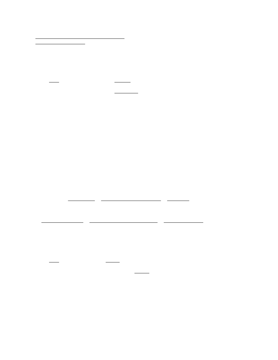
Girder Stress Check Section 5-5 G2 Node 36
Strength - Bottom Flange
Check the bottom (box) flange for strength at this section according to the provisions of Article 6.11.8.2
for compression flanges in negative flexure. The section will be checked for the Strength I limit state in
the following computations. Assume one longitudinal compression flange stiffener.
Load
Moment
Steel
-3,154 k-ft
All values are from Table C1
Deck
-12,272 k-ft
Unfactored results are shown
Total noncomposite
-15,426 k-ft
Superimposed DL
-1,932 k-ft
FWS
-2,541 k-ft
LL + IM
-8,127 k-ft
The dynamic load allowance has been applied to the live load according to Article 3.6.2. Multiple
presence factors, specified in Table 3.6.1.1.2-1 were also considered in the live load analysis.
Compute the factored vertical bending stress in the bottom flange due to dead and live load. For loads
applied to the composite section, assume a cracked section, as specified in Article 4.5.2.2. Section
properties are from Table C5. Shear lag need not be considered since the box flange width does not
exceed one-fifth of the span of the bridge (Article C6.11.1.1). The longitudinal vertical bending stress is,
therefore, assumed to be uniform across the flange because shear lag need not be considered and
because it is assumed that the spacing of the internal bracing is such that the longitudinal warping
stress at the strength limit state is limited to 10 percent of the stresses due to major-axis bending
(Article C6.7.4.3).
f
bot flg
= f
bu
=
γ
DC
M
DC
C
nc
I
nc
γ
DC2
M
DC2
γ
DW
M
DW
+
(
)
C
3n
I
3n
+
γ
LL
M
LL
C
n
I
n
+
12
(
)
η
=
1.25 15426
−
(
) 38.81
(
)
438966
1.25 1932
−
(
)
1.5 2541
−
(
)
+
[
]39.76
454805
+
1.75 8127
−
(
) 41.55
(
)
484714
+
12
(
) 1
( )
41.6
−
=
ksi
(C)
Compute the factored St. Venant torsional shear stress, f
v
, in the bottom flange due to the noncomposite
loads. Torques are taken from Table C3.
Load
Torque
Steel
1.25(-22)
= -28 k-ft
Deck
1.25(48)
= 60 k-ft
Total Noncomposite Torque
= 32 k-ft
D-25

A
o
=
120
81
+
(
)
2
80.25
7.25
+
(
)
1
144
61.1
=
ft
2
Therefore, the factored torsional shear stress is:
f
v
=
T
2A
o
t
fc
=
2337 12
(
)
2 61.1
(
) 144
(
) 1.5
(
)
1.06
=
ksi
f
v tot
= 0.016
1.06
+
1.08
=
ksi
Check the applied torsional stress against the factored torsional shear resistance of the flange, F
vr
.
F
vr
=
0.75
φ
v
F
yf
3
Eq (6.11.1.1-1)
=
0.75 1.0
(
)
50
3
21.65
=
ksi > f
v tot
= 1.08 ksi OK
Girder Stress Check Section 5-5 G2 Node 36
Strength - Bottom Flange (continued)
The nominal flexural resistance of the compression flange of a longitudinally stiffened flange is determined
according to Article 6.11.8.2.3.
Compute the enclosed area within the noncomposite box section, A
o
.
A
o
=
120
83
2 1
( )
−
[
]
+
[
]
2
1.5
2
78
+
3
2
+
1
144
56
=
ft
2
f
v
=
T
2A
o
t
fc
=
32 12
(
)
2 56
(
) 144
(
) 1.5
(
)
0.016
=
ksi
Eq (6.11.8.2.2-6)
where: T = internal torque from factored loads (k-ft); t
f
= bottom flange thickness (in.)
Compute the factored torsional shear stress in the bottom flange due to the composite loads. Torques
are taken from Table C3.
Load
Torque (-)
Torque (+)
SupImp DL
1.25(-149)
= -186 k-ft
1.25(193) = 241 k-ft
FWS
1.50(-197)
=
-296 k-ft
1.50(254) = 381
k-ft
LL + IM
1.75(-863)
= -1,510 k-ft
1.75(980) = 1,715 k-ft
Total Comp. Torque
= -1,992 k-ft
= 2,337 k-ft
Since
1992
−
2337
<
, use positive torque.
Compute the enclosed area of the composite box, A
o
.
D-26
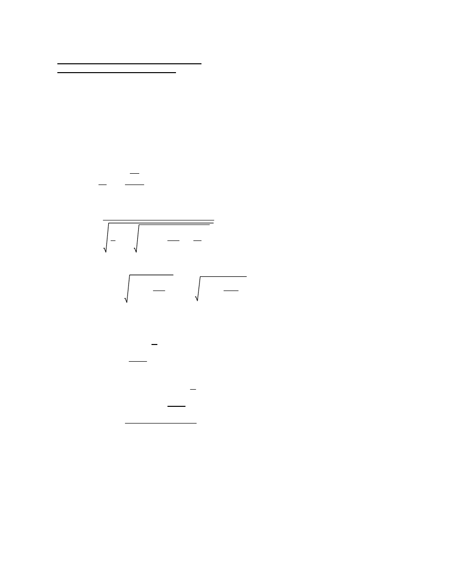
t
fc
= thickness of the flange plate (in.)
w = larger of the width of the flange between longitudinal flange stiffeners or
the distance from a web to the nearest longitudinal flange stiffener (in.)
where: n = number of equally spaced longitudinal flange stiffeners
I
s
= actual moment of inertia of one longiudinal flange stiffener about an axis
parallel to the flange at the base of the stiffener (in
4
)
Eq (6.11.8.2.3-3)
5.34
2.84
I
s
w t
fc
3
1
3
+
n
1
+
(
)
2
5.34
≤
k
s
=
Eq (6.11.8.2.3-1)
8I
s
w t
fc
3
1
3
k =
for flanges with one longitudinal stiffener (n = 1), the plate-buckling coefficient for uniform
normal stress, k, is taken as:
Eq (6.11.8.2.2-5)
1
3
1.08
50
2
−
0.999
=
=
1
3
f
v
F
yc
2
−
∆ =
where:
Eq (6.11.8.2.2-8)
0.57
1
2
∆
∆
2
4
f
v
F
yc
2
k
k
s
2
+
+
R
1
=
81
2
1.5
27
=
=
w
t
fc
λ
f
=
Compute the slenderness ratio for the compression flange to determine which nominal flexural resistance
equation to use. According to Article 6.11.8.2.3, "b
fc
" is taken as "w" in the following design. The variable
"w" is taken as the larger of the width of the flange between longitudinal flange stiffeners or the distance
from a web to the nearest longitudinal flange stiffener.
Although the torques on the noncomposite and composite box act in opposite directions, the resulting
shear flows are conservatively added together in determining the total factored torsional shear stress.
Generally this is acceptable because of the small magnitude of the noncomposite torque.
Girder Stress Check Section 5-5 G2 Node 36
Strength - Bottom Flange (continued)
D-27
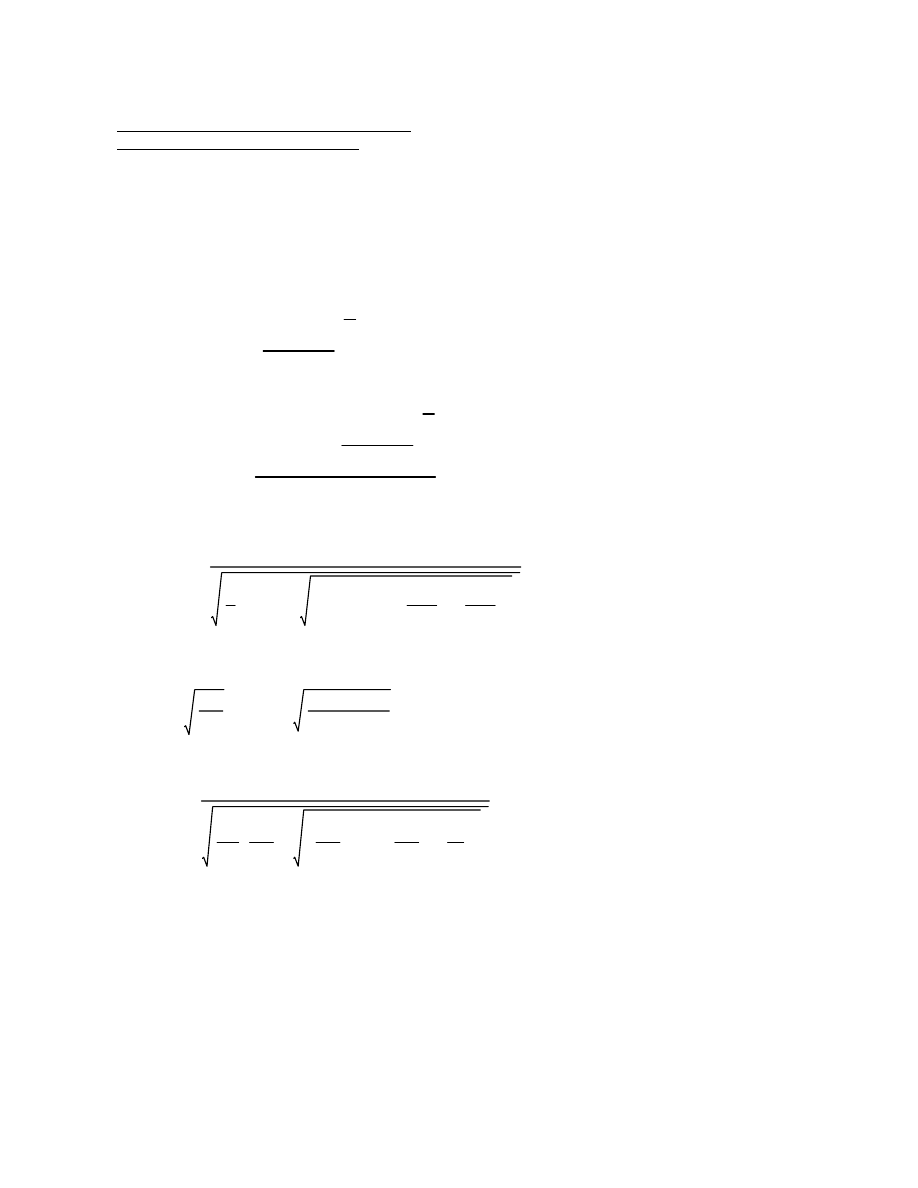
ksi
0.999
0.4
−
(
) 50
(
)
29.95
=
=
Eq (6.11.8.2.2-7)
∆
0.4
−
(
)F
yc
F
yw
≤
F
yr
=
where:
Eq (6.11.8.2.2-9)
1.23
1
1.2
F
yr
F
yc
F
yr
F
yc
2
4
f
v
F
yc
2
k
k
s
2
+
+
R
2
=
<
λ
f
= 27.0
0.57
2.81 29000
(
)
50
23.01
=
=
R
1
k E
F
yc
0.57
1
2
0.999
0.999
(
)
2
4
1.08
50
2
2.81
2.33
2
+
+
0.57
=
R
1
=
5.34
2.84
378.7
40.5 1.5
(
)
3
1
3
+
1
1
+
(
)
2
2.33
=
k
s
=
8 378.7
(
)
40.5 1.5
(
)
3
1
3
2.81
=
k =
in
4
48.7
8.38 6.275
(
)
2
+
378.7
=
I
l
=
Compute the moment of inertia about the base of the stiffener.
From the AISC Manual of Steel Construction: I
l
= 48.7 in
4
; A = 8.38 in
2
; N.A.= 6.275 in. from the tip of
the stem (i.e. edge of the bottom flange)
Girder Stress Check Section 5-5 G2 Node 36
Strength - Bottom Flange (continued)
D-28
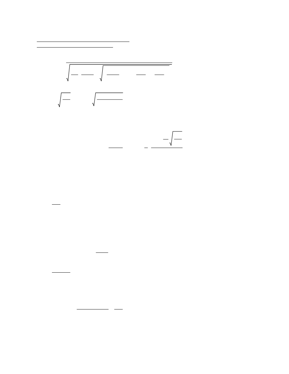
Eq (6.10.1.10.2-3)
1
a
wc
1200
300a
wc
+
2D
c
t
w
λ
rw
−
−
1.0
≤
R
b
=
Since this relation is not satisfied, R
b
must be calculated using Eq (6.10.1.10.2-3)
>
λ
rw
= 137
2 41.28
(
)
0.5625
147
=
in. (along the inclined web)
41.55
1.5
−
(
)
4.123
4.0
41.28
=
D
c
=
D
c
is calculated using the provisions of Article D6.3.1. These provisions state that for composite
sections in negative flexure, D
c
is computed for the section consisting of the steel girder plus the
longitudinal deck reinforcement. For this example, the larger value between "Comp DL Bars" and
"Comp LL Bars" from Table C5 was used.
Eq (6.10.1.10.2-2)
2D
c
t
w
λ
rw
≤
R
h
is taken as 1.0 from Article 6.10.1.10.1 and R
b
is calculated using the provisions of Article
6.10.1.10.2. For composite sections in negative flexure that satisfy Eq 2, R
b
is also taken as 1.0
since the web slenderness, 2D
c
/t
w
, is at or below the value at which the theoretcial elastic
bend-buckling stress is equal to F
yc
at the strength limit state.
Eq (6.11.8.2.2-2)
R
b
R
h
F
yc
∆
∆
F
yr
R
h
F
yc
−
1
sin
π
2
R
2
w
t
fc
F
yc
k E
−
R
2
R
1
−
−
−
F
nc
=
The nominal flexural resistance of the compression flange, F
nc
, is taken as:
> 27.0, therefore, use Eq (6.11.8.2.2-2)
1.23
2.81 29000
(
)
50
49.7
=
=
R
2
k E
F
yc
1.23
1
1.2
29.95
50
29.95
50
2
4
1.08
50
2
2.81
2.33
2
+
+
1.23
=
R
2
=
Girder Stress Check Section 5-5 G2 Node 36
Strength - Bottom Flange (continued)
D-29
To estimate the shear stress in the bottom flange due to the internal diaphragm shear, assume a 1 in. x
12 in. top flange for the diaphragm. As specified in Article C6.11.8.1.1, a flange width equal to 18 times
its thickness (18 x 1.5 in. = 27 in.) may be considered effective with the internal diaphragm. The
diaphragm is assumed to be 78 inches deep and 1 inch thick. From separate calculations, the moment
of inertia of the effective section is 112,375 in
4
and the neutral axis is located 31.05 in. above the
mid-thickness of the bottom flange. Subsequent calculations on page D-34 indicate that the total
factored vertical component of the diaphragm shear is 1406 kips.
From previous calculations, the total factored St. Venant torsional shear stress in the bottom flange, f
v
, is
equal to 1.08 ksi.
Article C6.11.8.1.1 states that in general, bottom box flanges at interior-pier sections are subjected to
biaxial stresses due to major-axis bending of the box section and major-axis bending of the internal
diaphragm over the bearing sole plate. The flange is also subject to shear stresses due to the internal
diaphragm vertical shear, and in cases where it needs to be considered, the St. Venant torsional shear.
For a box supported on two bearings (the case in this example), bottom-flange bending stresses due to
bending of the diaphragm over the bearing sole plates are relatively small and will be neglected for
simplicity in this example.
Eq (6.11.7.2.1-1)
f
bu
= |-41.6| ksi <
φ
f
F
nc
= 49.25 ksi OK
ksi
0.997 1.0
(
) 50
(
) 0.999
0.999
29.95
1.0 50
(
)
−
1
sin
π
2
1.23
81
2
1.5
50
2.81 29000
(
)
−
1.23
0.57
−
−
−
49.25
=
F
nc
=
1
0.373
1200
300 0.373
(
)
+
2 41.28
(
)
0.5625
137
−
−
0.997
=
R
b
=
Eq (6.10.1.10.2-4)
λ
rw
= 137
2 41.28
(
) 0.5625
(
)
83 1.5
(
)
0.373
=
=
Eq (6.10.1.10.2-5)
2D
c
t
w
b
fc
t
fc
a
wc
=
where:
Girder Stress Check Section 5-5 G2 Node 36
Strength - Bottom Flange (continued)
D-30
where
σ
1
,
σ
2
are the maximum and minimum principle stresses in the diaphragm
σ
1
2
σ
1
σ
2
−
σ
2
2
+
F
y
≤
The combined principal stresses in the diaphragm due to the factored loads is checked using the general
form of the Huber-von Mises-Hencky yield criterion.
ksi
1.0 0.997
(
) 1.0
(
) 50
49.85
=
<
ksi
41.6
−
(
)
2
41.6
−
(
) 0
( )
−
0
( )
2
+
3 5.24
1.08
+
(
)
2
+
43.02
=
R
b
= 0.997 (previously calculated)
R
h
= 1.0 (Article 6.10.1.10.1)
= taken as 0.0 ksi for a box supported on two bearings
f
by
= stress in the flange due to the factored loads caused by major-axis bending of the internal
diaphragm over the bearing sole plate
The factored vertical bending stress in the bottom flange, f
bu
, was computed earlier to be -41.6 ksi.
Eq (C6.11.8.1.1-1)
f
bu
2
f
bu
f
by
−
f
by
2
+
3 f
d
f
v
+
(
)
2
+
φ
f
R
b
R
h
F
yc
≤
The effect of bending in the plane of the diaphragm for boxes supported on two bearings is insignificant
and was, therefore, ignored in the design of the example girder. The effect of these forces on a box
supported on a single bearing is likely to be more significant and should be considered. The effective
section specified in Article C6.11.8.1.1 may be used to compute the flange bending stress about the
tangential z-axis due to bending of the internal diaphragm over the sole plate. In this case, the resulting
minimum and maximum principal stresses in the flange should be input into the more general form of the
Huber-von Mises-Hencky yield criterion given as follows:
ksi
1.08
5.24
+
6.32
=
f
v tot
=
Eq (C6.11.8.1.1-2)
ksi
1406
27
2
1.5
(
) 31.05
(
)
112375 1.5
(
)
5.24
=
=
VQ
I t
fc
( )
f
d
=
The shear stress in the flange, f
d
, caused by the internal diaphragm vertical shear due to factored loads is
approximated as:
Girder Stress Check Section 5-5 G2 Node 36
Strength - Bottom Flange (continued)
D-31
ksi < 36 ksi OK
6.32
2
6.32
(
) 6.32
−
(
)
−
6.32
−
(
)
2
+
10.95
=
Check the combined principal stresses.
6.32 ksi
=
0
( )
2
6.32
2
+
0
σ
1,2
=
±
±
Since the example box is supported on two bearings, the stress in the diaphragm due to vertical bending
of the diaphragm over the bearing sole plate is typically relatively small and will be neglected for simplicity
in this example.
σ
z
is also typically neglected. If no bending is assumed, the two principal stresses are
simply equal to the tensile and compressive stresses with a magnitude equal to the shear stress.
σ
y
= stress in the diaphragm due to vertical bending of the diaphragm over the bearing sole plate
σ
z
= stress in the diaphragm due to bending of the diaphragm about its longitudinal axis
f
v
= shear stress in the diaphragm
F
y
= specified minimum yield stress of the diaphragm
σ
y
σ
z
−
2
2
f
v
2
+
σ
y
σ
z
+
2
σ
1
,
σ
2
=
±
Girder Stress Check Section 5-5 G2 Node 36
Strength - Bottom Flange (continued)
D-32
Girder Stress Check Section 5-5 G2 Node 36
Longitudinal Flange Stiffener
Try a WT 8x28.5 structural tee for the longitudinal stiffener with the stem welded to the bottom flange.
The projecting width, b
l
, of the stiffener must satisfy the following requirement:
b
l
0.48t
s
E
F
yc
≤
=
0.48 0.715
(
)
29000
50
8.27
=
in.
Eq (6.11.11.2-1)
where t
s
is taken as the flange thickness of the structural tee since each half-flange buckles
similarly to a single plate connected to a web.
For structural tees, b
l
should be taken as one-half the width of the flange.
b
l
= 7.12/2 = 3.56 in. < 8.27 in. OK
According to Article 6.7.4.3, transverse top and bottom bracing members (i.e. top and bottom struts of
internal cross frames) are required to ensure that the cross section shape is retained. Whenever
longitudinal flange stiffeners are present, the bottom transverse bracing members are to be attached to the
longitudinal stiffener(s) to better control the transverse distortion of the box flange. At other locations, the
bottom transverse member is to be attached directly to the box flange. The cross-sectional area and
stiffness of the top and bottom transverse bracing members is not to be less than the area and stiffness of
the diagonal members. At the pier section (the point of maximum compressive flexural stress in a box
flange in most cases), the bottom transverse bracing member, when properly attached to the longitudinal
flange stiffener, can be assumed to provide the required transverse stiffening of the box flange. Use a
W10x68 (I = 394 in
4
) for the bottom transverse bracing member.
The longitudinal flange stiffener should be attached to the internal diaphragm with a pair of clip angles as
shown in Figure D-2 (page D-81).
D-33
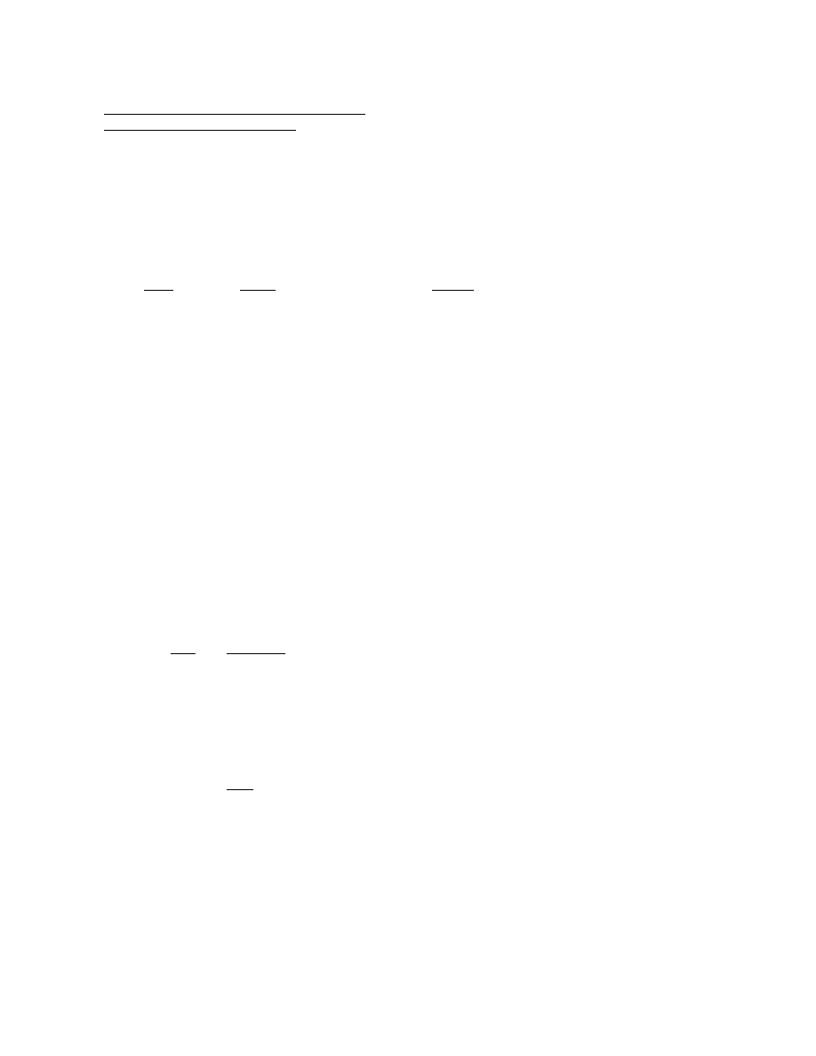
kips
579
1.87
−
577.1
=
V
b
=
kips
1.93
78
80.4
1.87
=
(V
T
)
v
=
The vertical component of V
T
is computed as:
kips
0.024 80.4
(
)
1.93
=
V
T
=
Eq (C6.11.1.1-1)
k/in.
32
2 56
(
) 12
(
)
0.024
=
=
T
2A
o
f
v
=
The sum of the total steel plus deck factored shears is equal to 1.25(93 + 370) = 579 kips. Referring to
the calculations on page D-25, the shear flow in the noncomposite box is computed as:
Compute the maximum factored shear stress in the diaphragm web. First, separate out the shears due
to bending, V
b
, and due to St. Venant torsion, V
T
.
The internal diaphragm is subject to vertical bending over the bearing sole plates in addition to shear.
Therefore, Article 6.11.8.1.1 requires that the principal stresses in support diaphragms not exceed the
factored compressive resistance given by Eq (C6.11.8.1.1-1), which is a yield criterion for combined
stress. The example box is supported by two bearings, therefore, f
by
in this equation is taken as 0.0 ksi
since it is typically relatively small.
kips
1.25 93
370
+
85
+
(
)
1.5 113
(
)
+
1.75 315
(
)
+
1406
=
V
u
=
Load
Shear
Source
Steel
47 + |-46|
= 93 k
3D Finite Element Analysis
Deck
185 + |-185|
= 370 k
(in critical web from Table C2)
SupImp
44 + |-41|
= 85 k
Unfactored results are shown
FWS
58 + |-55|
= 113 k
LL + IM
160 + |-155|
= 315 k
Compute the maximum factored vertical shear in the diaphragm.
Try a 1-inch thick A36 diaphragm plate.
Article 6.11.1 directs the designer to the provisions of Article 6.7.4 for general design considerations for
cross-frames and diaphragms.
Girder Stress Check Section 5-5 G2 Node 36
Design of the Internal Diaphragm
D-34
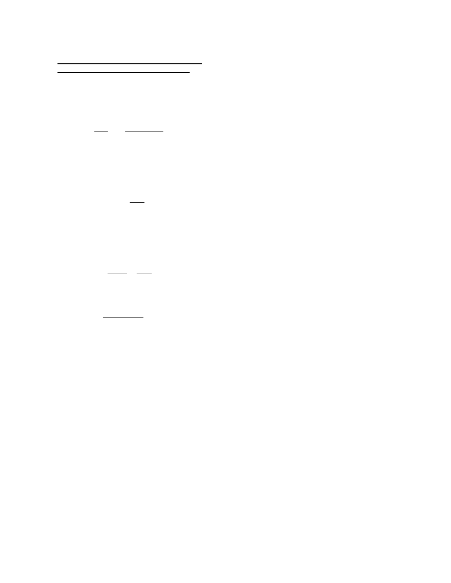
ksi
1.61
16.4
+
18.01
=
f
v
= (f
v
)
T
+ (f
v
)
b
=
Therefore, for this case, since bending in the plane of the diaphragm is ignored, the maximum principal
stress is simply equal to the total factored shear stress.
As mentioned previously, for a box supported on two bearings, the bending stresses in the plane of the
diaphragm due to vertical bending of the diaphragm over the bearing sole plates are relatively small and
will be neglected in this example for simplicity. For a box supported on a single bearing, the effect of the
bending stresses in the plane of the diaphragm are likely to be more significant and should be considered.
As specified in Article C6.11.8.1.1, a width of the bottom (box) flange equal to 18 times its thickness may
be considered effective with the diaphragm in resisting bending.
ksi
577.1
703
+
78 1.0
(
)
16.4
=
(f
v
)
b
=
The average factored shear stress due to bending is equal to:
ksi
0.024
1.0
1.59
1.0
+
1.61
=
(f
v
)
T
=
The factored shear stress due to torsion is therefore equal to:
kips
827
124
−
703
=
V
b
=
kips
127.8
78
80.4
124
=
(V
T
)
v
=
The vertical component of V
T
is computed as:
kips
1.59 80.4
(
)
127.8
=
V
T
=
Eq (C6.11.1.1-1)
k/in.
2337
2 61.1
(
) 12
(
)
1.59
=
=
T
2A
o
f
v
=
The sum of the total Superimposed Dead Load, including the FWS, plus Live Load factored shears is
equal to 1.25(85) + 1.5(113) + 1.75(315) = 827 kips. Referring to the calculations on page D-26, the
shear flow in the composite box is computed as:
Girder Stress Check Section 5-5 G2 Node 36
Design of Internal Diaphragm (continued)
D-35
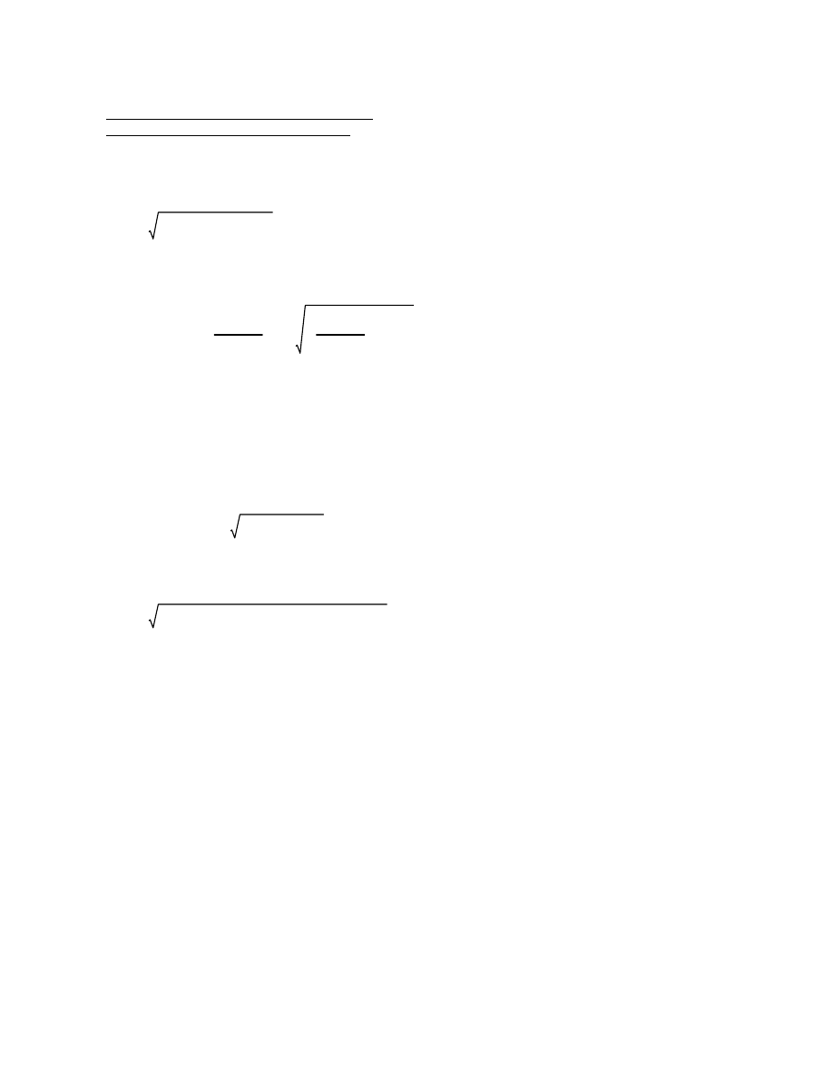
18.01 ksi
Check the combined principal stresses.
18.01
2
18.01
(
) 18.01
−
(
)
−
18.01
−
(
)
2
+
31.19
=
ksi < F
y
= 36 ksi OK
Compute the shear resistance according to Article 6.11.9 which specifies the use of the provisions of
Article 6.10.9 for the horizontally curved I-girder design. Separate calculations indicate that C = 1.0.
V
u
φ
v
V
n
≤
Eq (6.10.9.1-1)
V
n
= V
cr
= CV
p
Eq (6.10.9.2-1)
V
p
= 0.58F
y
Dt
w
=
0.58 36
(
) 78
(
) 1.0
(
)
1629
=
kips
Eq (6.10.9.2-2)
V
n
= 1.0 1629
(
)
1629
=
kips
V
u
= 1406 k <
φ
v
V
n
= 1.0(1629) = 1629 k OK
Girder Stress Check Section 5-5 G2 Node 36
Design of Internal Diaphragm (continued)
The combined principal stresses in the diaphragm due to the factored loads is checked using the general
form of the Huber-von Mises-Hencky yield criterion (similarly calculations shown previously).
σ
1
2
σ
1
σ
2
−
σ
2
2
+
F
y
≤
where
σ
1
,
σ
2
are the maximum and minimum principle stresses in the diaphragm
±
σ
1
,
σ
2
=
σ
y
σ
z
+
2
σ
y
σ
z
−
2
2
f
v
2
+
where:
σ
y
= 0
σ
z
= 0
If no bending is assumed, the two principal stresses are simply equal to the tensile and compressive
stresses with a magnitude equal to the shear stress.
±
±
σ
1,2
= 0
0
( )
2
18.01
2
+
=
D-36
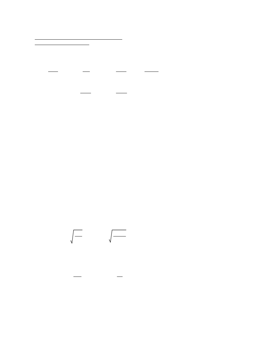
in
2
18 1.0
(
)
2
36
50
12.96
=
=
18t
w
2
F
yw
F
ys
A
d
=
Compute the effective area of the diaphragm, A
d
, to which the stiffeners are attached (t
w
= 1.0 in.)
according to the provisions of Article 6.10.11.2.4b.
Eq (6.10.11.2.2-1)
> 11 in. OK
0.48 1
( )
29000
50
11.6
=
=
b
t
0.48 t
p
E
F
ys
≤
Try 2-plates 11 in. x 1 in.; Bearing area = 2(11 - 1.0)(1.0) = 20.0 in
2
(Assume 1 in. for stiffener clip).
Use bars with F
y
= 50 ksi. Compute the maximum permissible width-to-thickness ratio of the stiffener
plates according to Eq (6.10.11.2.2-1).
Assume that the bearings are fixed at the piers. Thus, there will be no expansion causing eccentric
loading on the bearing stiffeners. Bearing stiffeners should be attached to diaphragms rather than
inclined webs. According to Article 6.11.11.1, design the bearing stiffeners attached to the diaphragms
using the provisions of Article 6.10.11.2.4b. The provisions are applied to the diaphragm rather than the
web.
Ignore uplift.
kips
1.25 93
370
+
11
+
(
)
1.5 15
(
)
+
1.75 287
(
)
+
1117
=
R
right
=
kips (controls)
1.25 79
238
+
85
+
(
)
1.5 113
(
)
+
1.75 294
(
)
+
1187
=
R
left
=
Reaction Location
Load
Left
Right
Source
Steel
79 k
93 k
3D Finite Element Analysis
Deck
238 k
370 k
(Not tabulated)
SupImp
85 k
11 k
Unfactored results are shown
FWS
113 k
15 k
Total DL
515 k
489 k
LL + IM
294 k
287 k
-65 k
-16 k
uplift
Compute the factored reactions.
Girder Stress Check Section 5-5 G2 Node 36
Design of Bearing Stiffeners
D-37

Eq (6.9.4.1-3)
K
l
r
s
π
2
F
y
E
λ =
Calculate P
n
. Check if
λ is greater than or less than 2.25.
where: P
n
= nominal compressive resistance as specified in Article 6.9.4
φ
c
= resistance factor according to Article 6.5.4.2
Eq (6.9.2.1-1)
P
r
=
φ
c
P
n
Assume the concentrated load is applied concentrically with respect to the centroidal axes of the bearing
stiffener. The bearing stiffener assembly may then be designed as a centrally loaded compression
member according to the provisions of Article 6.10.11.2.4 for the axial resistance of bearing stiffeners.
These provisions state that the factored axial resistance, P
r
, is determined using Article 6.9.2.1 where the
radius of gyration is computed about the mid-thickness of the web and the effective length shall be taken
as 0.75D.
1187 k < 1.0(1400) = 1400 k OK
The resistance factor,
φ
b
, is taken to be 1.0 from Article 6.5.4.2.
k
1.4 20
(
) 50
(
)
1400
=
(R
sb
)
n
=
F
ys
= 50 ksi
= 20 in
2
A
pn
= area of the projecting elements of the stiffener outside the web-to-flange fillet welds
but not beyond the edge of the flange (in
2
)
where:
Eq (6.10.11.2.3-2)
1.4A
pn
F
ys
(R
sb
)
n
=
The nominal bearing resistance for the fitted ends, (R
sb
)
n
, is:
Eq (6.10.11.2.3-1)
(R
sb
)
r
=
φ
b
(R
sb
)
n
The factored bearing resistance for the fitted ends of bearing stiffeners is determined using the provisions
of Article 6.10.11.2.3.
Girder Stress Check Section 5-5 G2 Node 36
Design of Bearing Stiffeners (continued)
D-38
P
u
= 1187 k < P
r
= 1559 k OK
k
0.9
(
) 1732
(
)
1559
=
P
r
=
P
r
=
φ
c
P
n
Eq (6.9.4.1-1)
k
0.66
0.022
50
(
) 34.96
(
)
1732
=
P
n
= 0.66
λ
F
y
A
s
=
< 2.25, use Eq (6.9.4.1-1) for P
n
0.75 80.4
(
)
5.39
π
( )
2
50
29000
0.022
=
λ =
Therefore;
1014
34.96
5.39
=
r
s
=
in
4
2
1 11
(
)
3
12
11 6
( )
2
+
1014
=
I =
in
2
12.96
2
( )11
+
34.96
=
A =
I
A
r
s
=
Calculate r
s
.
Girder Stress Check Section 5-5 G2 Node 36
Design of Bearing Stiffeners (continued)
D-39
Eq (6.9.4.2-1)
b
t
k
E
F
y
≤
The provisions of Article 6.9.4.1 are used to determine the nominal compressive resistance of non-
composite members when Eq (6.9.4.2-1) is satisfied. There is no eccentricity with respect to the y-axis.
< 140 OK
0.75 222
(
)
2.65
62.8
=
=
K
l
r
y
Check buckling about the y-axis. The limiting slenderness ratio for compression members is specified
in Article 6.9.3. Use the effective length factor, as specified in Article 4.6.2.5, for bolted connections at
both ends.
Try: WT 9x48.5
From AISC Manual: A = 14.3 in
2
; y = 1.91 in.; S
x
= 12.7 in
3
; r
x
= 2.56 in.; r
y
= 2.65 in.
Try a structural tee (WT) section with the stem down and its flange bolted to the bottom of the tub
flanges, which is the preferable method of connection. Assume that a timber member will brace the
structural tee at mid-length in the vertical plane during construction. Therefore, the unbraced length with
respect to the x-axis equals 222/2 = 111 in. The unbraced length with respect to the y-axis = 222 in.
in.
104
2
196
2
+
222
=
L
c
=
Tub width at top = 120 in.; top flange width = 16 in.
Clear distance between top flanges = 120 - 16 = 104 in.
Distance between cross frames = 16.3 feet = 195.6 in., say 196 in.
Compute the bracing length, L
c
.
kips (C)
1.25 113
−
(
)
141
−
=
Load Factor = 1.25 (Article 3.4.2); Design load =
Load
Force
Source
Steel
-13 k
Table C4 (from 3D finite element analysis)
Cast #1
-100 k
Unfactored results are shown
-113 k
Top flanges of tub girders subjected to torsional loads need braced so that the section acts as a
pseudo-box for noncomposite loads applied before the concrete deck hardens or is made composite.
Design the top (tub) flange single diagonal bracing member in Span 1 of Girder 2 in the first bay adjacent
to the abutment (Element 1 in Table C4). Article 6.11.1 specifies that the top lateral bracing for tub
sections must satisfy the provisions of Article 6.7.5. Tub flange bracing must be designed to satisfy the
constructibility limit state as well as the final condition. Since lateral bracing is not required for
continuously braced flanges, investigate the bracing for the construction staging only. The bracing is
designed according to the provisions of Articles 6.8 and 6.9 for tension and compression, respectively .
Wind lateral loading is neglected in this example.
Girder Stress Check G2 Span 1 Bay 1
Top Flange Bracing Member Design - Constructibility
D-40
Check buckling about the x-axis.
Consider the eccentricity of the connection.
Compute the moment due to the eccentricity of the force at the flange face.
M
ux
= 141 1.91
(
)
269
=
k-in
Verify that the limiting slenderness ratio of Article 6.9.3 is satisfied.
K
l
r
x
=
0.75 111
(
)
2.56
32.5
=
<
140 OK
Use the provisions of Article 6.9.2.2 to check the resistance of the member under combined axial
compression and flexure.
P
u
P
r
=
141
−
483.3
0.292
=
> 0.2, therefore, use Eq (6.9.2.2-2)
P
u
P
r
8.0
9.0
M
ux
M
rx
M
uy
M
ry
+
+
1.0
≤
Eq (6.9.2.2-2)
Girder Stress Check G2 Span 1 Bay 1
Top Flange Bracing Member Design - Constructibility (continued)
The plate buckling coefficient is taken as 0.75 from Table 6.9.4.2-1 for stems of rolled tees. The width, b,
is taken as the full depth of the tee section and thickness, t, is for that of the stem.
9.295
0.535
17.4
=
<
0.75
29000
50
18.1
=
OK
Therefore, the provisions of Article 6.9.4.1 apply. Determine if Eq (6.9.4.1-1 or -2) is to be used for the
nominal compressive resistance, P
n
.
λ =
K
l
r
s
π
2
F
y
E
=
0.75 222
(
)
2.65
π
2
50
29000
0.69
=
Eq (6.9.4.1-3)
Since
λ is less than 2.25, Eq (6.9.4.1-1) is used for the calculation of P
n
.
P
n
= 0.66
λ
F
y
A
s
Eq (6.9.4.1-1)
= 0.66
0.69
50
(
) 14.3
(
)
537
=
k
P
u
= |-141| k < P
r
=
φ
c
P
n
= 0.9(537) = 483.3 k OK
D-41
G = shear modulus of elasticity of steel, 11,200 ksi
I
y
= 100 in
4
E = 29,000 ksi
for stems in compression
M
n
1.0M
y
≤
for stems in tension, this is used for this example since the member is in
positive bending. 1.5M
y
was calculated previously as 79.38 k-ft.
M
n
1.5M
y
≤
where:
AISC Eq (F1-15)
π E I
y
G J
L
b
B
1
B
2
+
+
M
n
= M
cr
=
For tee sections, use Chapter F1.2c in the Specification section of the AISC Manual.
Lateral-torsional buckling:
M
p
= 50(22.6)/12 = 93.75 k-ft > 79.38 k-ft, therefore, M
n
= 79.38 k-ft
1.5M
y
= 79.38 k-ft
k-ft
50 12.7
(
)
12
52.92
=
M
y
= F
y
S =
where:
AISC Eq (F1-1)
F
y
Z
1.5M
y
≤
M
n
= M
p
=
Yielding:
Use the provisions of Article 6.12.2.2.4 for noncomposite structural tees. The nominal bending
resistance is the lowest value as limited by yielding, lateral torsional buckling or local buckling of the
elements. The Specifications direct the designer to the AISC Manual for Steel Construction for the
determination of M
n
. The nominal flexural resistance, M
n
, is the lowest value according to the limit
states of: yielding, lateral- torsional buckling, flange local buckling and web local buckling. For unbraced
compact and noncompact tees, only the yielding and lateral-torsional buckling limit states are applicable.
Eq (6.12.1.2.1-1)
M
rx
=
φ
f
M
n
Determine the factored flexural resistance about the x-axis using the provisions of Article 6.12 for the
miscellaneous flexural members.
Girder Stress Check G2 Span 1 Bay 1
Top Flange Bracing Member Design - Constructibility (continued)
D-42
< 1.0 OK
0.292
8.0
9.0
269
79.38 12
(
)
0
+
+
0.54
=
M
rx
is taken as the value for yielding, 1.0(79.38) = 79.38 k-ft in Eq (6.9.2.2-2)
619.2 k-ft > 1.5M
y
k-in
π 29000 100
(
) 11200
(
) 2.88
(
)
222
0.567
1
0.567
2
+
+
7430
=
M
n
=
Therefore, the lateral-torsional buckling nominal flexural resistance is:
AISC Eq (F-16)
2.3
9.295
222
100
2.88
0.567
=
=
2.3
d
L
b
I
y
J
B =
11.145 0.870
(
)
3
8.425 0.535
(
)
3
+
3
2.88
=
=
Σ
b t
3
3
J = torsional constant =
Girder Stress Check G2 Span 1 Bay 1
Top Flange Bracing Member Design - Constructibility (continued)
D-43

Compute D
c
considering the transverse stiffeners according to Bethlehem Guide Equation (A3d) since
Article 6.11.1.1 permits transverse stiffeners to be considered effective in resisting transverse bending.
D
c
= flexural rigidity of web
k-in
2
/in.
29000 1.5
(
)
3
12 1
0.30
2
−
(
)
8963
=
=
E
s
t
b
3
12 1
µ
s
2
−
D
b
=
k-in
2
/in.
3834 9.5
(
)
3
12 1
0.2
2
−
(
)
285345
=
=
E
c
t
a
3
12 1
µ
c
2
−
D
a
=
D
a
= flexural rigidity of deck; D
b
= flexural rigidity of bottom flange
Compute the transverse flexural rigidities of the deck and bottom flange from Bethlehem Guide Equations
(A3a) and (A3b), respectively.
Poisson's ratio for concrete,
µ
c
= 0.2 (Article 5.4.2.5); Poisson's ratio for steel,
µ
s
= 0.30
Transverse stiffener - try a plate 5.5 in. x 0.5 in.
I
comp
= 836,080 in
4
(from Table C5)
Minimum transverse stiffener spacing = 62 in. (Calculations not shown)
Cross frame spacing = 16.3 ft. = 196 in.
t
c
= web thickness = 0.5625 in.
t
b
= bottom flange thickness = 1.50 in.
t
a
= slab thickness = 9.5 in.
E
c
= 3,834 ksi; E
s
= 29,000 ksi
The fatigue loading produces a positive torque of 254 k-ft and a negative torque of -232 k-ft at the pier,
Section 5-5 Node 36, as given in Table C3. The total range of factored torque is 486 k-ft (5,832 k-in).
The "Design Guide to Box Girder Bridges," Bethlehem Steel Corporation, 1981, presents a method
developed by Wright and Abdel-Samed (1968) to estimate transverse bending stresses using the Beam
on Elastic Foundation Analogy (BEF). In this method, the deflection of the BEF is analogous to the
transverse bending stress.
The most critical condition is likely to be fatigue at the termination of fillet welds connecting transverse
stiffeners to the web (Category E).
Article 6.11.1.1 requires that the transverse bending stresses in webs and flanges be investigated and
determined by rational structural analysis. These provisions limit the transverse bending stresses due to
the factored loads at the strength limit state to 20 ksi. The transverse bending stress range due to cross-
section distortion must be checked for fatigue as specified in Article 6.11.5 and at the strength limit state.
Longitudinal warping stresses due to cross-section distortion are considered for fatigue as specified in
Article 6.11.5, but may be ignored at the strength limit state.
Girder Stress Check Section 5-5 G2 Node 36
Transverse Bending Stress
D-44
The stiffness of the transverse stiffener is assumed to be distributed evenly along the web.
Bethlehem Guide Eq (A3d)
k-in
2
/in.
29000 26.5
(
)
62
12395
=
=
E
s
I
s
d
D
c
=
in.
1
12
0.5
(
) 5.5
(
)
3
2.75
5.5
2
0.5625
+
1.0
−
2
+
1
12
0.5625
(
)
3
15.8
(
)
+
8.89
0.5625
2
1
−
2
+
26.5
=
I
s
=
in.
2.75 0.5625
5.5
2
+
8.89
0.5625
2
+
11.64
1.0
=
N.A. =
Area of stiffener = 5.5 x 0.5 = 2.75 in
2
Area of web = 15.8 x 0.5625 = 8.89 in
2
11.64 in
2
Compute the location of the neutral axis of the effective section from the web face.
in.
62
(
)tanh 5.6
62
80.4
5.6
62
80.4
1
0.3
2
−
(
)
15.8
=
d
o
=
h = c
c = 80.4 in.
d = 62 in. spacing of transverse stiffeners.
Bethlehem Guide Eq (A4)
d tanh 5.6
d
h
5.6
d
h
1
µ
s
2
−
d
o
=
Compute d
o
in Figure D-4 using Equation (A4) from the Bethlehem Guide.
Girder Stress Check Section 5-5 G2 Node 36
Transverse Bending Stress (continued)
D-45
where:
l
= the distance between cross frames (in.)
0.00327 196
(
)
0.64
=
β
l
=
in
-1
4
1
29000 836080
(
) 0.36
(
)
0.00327
=
β =
where: I = moment of inertia of the composite box
Bethlehem Guide Eq (A5)
4
1
EI
c
δ
1
β =
Compute the BEF stiffness parameter,
β, using Bethlehem Guide Equation (A5).
in
2
/k
120 81
(
)
24 120
81
+
(
)
80.4
12395
2 120
(
) 81
(
)
120
81
+
0.22 2 120
(
)
81
+
[
]
−
120
2
285345
81
120
81
+
0.22
−
+
0.36
=
δ
1
=
Bethlehem Guide Eq (A1)
ab
24 a
b
+
(
)
c
D
c
2ab
a
b
+
v 2a
b
+
(
)
−
a
2
D
a
b
a
b
+
v
−
+
δ
1
=
Compute
δ
1
, the box distortion per kip per inch of load without diaphragms, according to Equation (A1)
from the Bethlehem Guide.
1
12395
2 120
(
)
81
+
[
] 120
(
) 81
(
) 80.4
(
)
[
]
1
285345
81
(
) 120
3
( )
+
120
81
+
(
)
120
3
285345
2 80.4
(
) 120
2
120 81
(
)
+
81
2
+
12395
+
81
3
8963
+
0.22
=
v =
Bethlehem Guide Eq (A2)
1
D
c
2a
b
+
(
)abc
[
]
1
D
a
ba
3
+
a
b
+
(
)
a
3
D
a
2 c a
2
ab
+
b
2
+
(
)
D
c
+
b
3
D
b
+
v =
Compute the compatibility shear at the center of the box (bottom) flange according to Bethlehem Guide
Equation (A2).
Girder Stress Check Section 5-5 G2 Node 36
Transverse Bending Stress (continued)
D-46

in
-1
81 0.22
(
)
2 0.0527
(
)
169
=
F
d
=
bv
2S
F
d
=
For the bottom corner of the box,
in
3
/in.
1
( ) 0.5625
(
)
2
6
0.0527
=
S
=
Compute S (per inch) for unstiffened portions of the web (more critical than the bottom flange).
Bethlehem Guide Equation (A9a)
in
-1
81 0.22
(
)
2 0.084
(
)
106
=
=
bv
2S
F
d
=
Girder Stress Check Section 5-5 G2 Node 36
Transverse Bending Stress (continued)
The transverse bending stress range at the top or bottom corners of the box section may be determined
from Bethlehem Guide Equation (A8).
σ
t
= C
t
F
d
β
1
2a
(m
l
or T)
Bethlehem Guide Equation (A8)
where: C
t
= BEF factor for determining the transverse distortional bending stress from Bethlehem
Guide Figure A6.
m = uniform range of torque per unit length.
l
= cross frame spacing
a = distance between webs at the top of the box
T = range of concentrated torque
F
d
= (bv)/(2S) for bottom corner of the box
= a/(2S)[b/(a + b) - v] for top corner of box
S = section modulus of the transverse member (per inch)
Compute the section modulus, S, for stiffened portions of the web.
S =
I
c
=
26.5
5.5
0.5625
+
1.0
−
(
)
5.23
=
in
3
Compute S per inch.
S =
5.23
62
0.084
=
in
3
/in.
D-47
The transverse bending stress range caused by the fatigue loading is negligible in this case.
The quantity, q, in Figure A6 represents the ratio of the diaphragm brace stiffness to the box stiffness per
unit length. For the
β
l
value in this example, the curves for q = 1,000 to infinity are clustered around a C
t
value of 0.03. Therefore, C
t
= 0.03 is used. For other cases, q may be calculated from Equation (A6) in
the Bethlehem Guide (not shown). An additional example of the computation of transverse bending
stresses is also given in the Bethlehem Guide.
ksi < 20.0 ksi OK
0.03 208
(
) 0.00327
(
)
5832
2 120
(
)
0.5
=
σ
t
=
Read C
t
from Bethlehem Guide Figure A6: C
t
= 0.03
Bethlehem Guide Equation (A8)
C
t
F
d
β
T
2a
σ
t
=
Compute f
t
using Bethlehem Guide Equation (A8).
(Unstiffened)
in
-1
(controls)
120
2 0.0527
(
)
81
201
0.22
−
208
=
F
d
=
(Stiffened)
in
-1
120
2 0.084
(
)
81
120
81
+
0.22
−
131
=
F
d
=
Bethlehem Guide Equation (A9b)
a
2S
b
a
b
+
v
−
For the top corner of the box, F
d
=
Girder Stress Check Section 5-5 G2 Node 36
Transverse Bending Stress (continued)
D-48
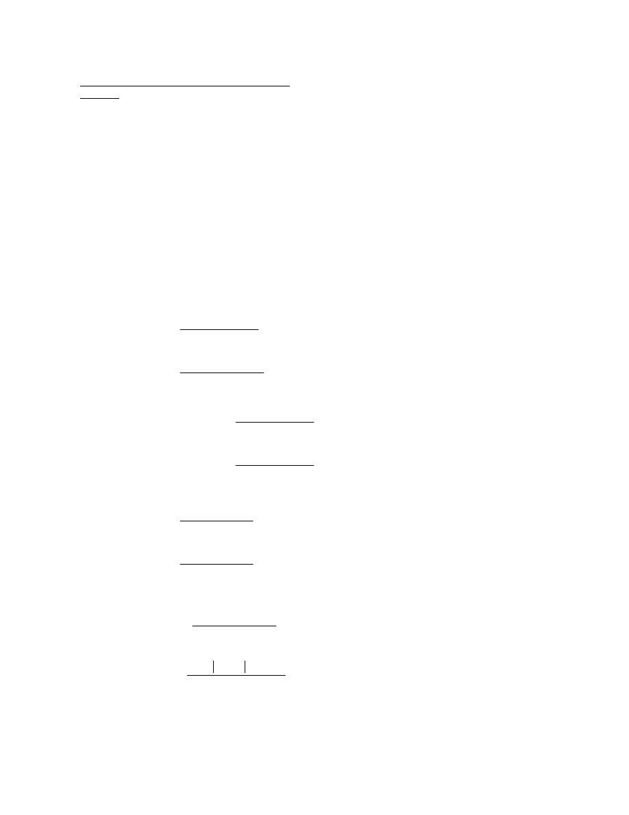
ksi for cracked section
w/o rebar (T)
1.75
3087
−
(
)
42.80
(
)
185187
12
(
)
14.98
=
f
top
(-LL + IM) =
ksi for n (C)
1.75 5264
(
) 10.78
(
)
479646
−
12
(
)
2.48
−
=
f
top
(LL + IM) =
ksi for cracked section
w/o rebar (C)
1.5 428
(
) 42.80
(
)
185187
−
12
(
)
1.78
−
=
f
top
(FWS) =
ksi for 3n (C)
1.5 428
(
) 24.27
(
)
354925
−
12
(
)
0.53
−
=
f
top
(FWS) =
ksi for cracked section
w/o rebar (C)
1.25 326
(
) 42.80
(
)
185187
−
12
(
)
1.13
−
=
f
top
(Superimposed DL) =
ksi for 3n (C)
1.25 326
(
) 24.27
(
)
354925
−
12
(
)
0.33
−
=
f
top
(Superimposed DL) =
ksi (C)
1.25 1941
(
) 42.80
(
)
185187
−
12
(
)
6.73
−
=
f
top
(Deck) =
ksi (C)
1.25 462
(
) 42.80
(
)
185187
−
12
(
)
1.6
−
=
f
top
(Steel) =
Compute the vertical bending stresses in the top extreme fiber of the steel at this section. Moments are
from Table C1 and section properties are from Table C5. In this particular case, the girder sections
immediately to the left and right of Section 2-2 are the same (except for the flange stiffener).
Check the bottom flange bending stress at Section 2-2, which is located 100 feet from the abutment.
Since this is the location of the bolted field splice in Span 1, it is desirable to terminate the longitudinal
flange stiffener at this location where the longitudinal stress at the free edge of the flange is zero. By
terminating the longitudinal flange stiffener at the free edge of the flange (at the bolted splice) and not
extending it further into the end span, fatigue of the base metal at the terminus of the stiffener-to-flange
weld need not be considered. The bottom flange splice plate inside the box must be split to permit the
stiffener to extend to the free edge of the flange (Figure D-5). Also, the compressive resistance of the
unstiffened bottom (box) flange on the side of the field splice directly across from the stiffener termination
must be checked at the strength limit state to ensure that the stiffener can be terminated at this section.
The section properties of the section without the flange stiffener are used below. The effect of the
concrete reinforcement in the stress calculation is neglected in this example.
Girder Stress Check Section 2-2 G2 Node 20.3
Stresses
D-49

Girder Stress Check Section 2-2 G2 Node 20.3
Stresses (continued)
Compute the factored vertical bending stress in the top flange at the strength limit state.
f
top
=
1.6
−
6.73
−
(
)
+
0.33
−
(
)
+
0.53
−
(
)
+
2.48
−
(
)
+
11.67
−
=
ksi
f
top
=
1.6
−
6.73
−
(
)
+
1.13
−
(
)
+
1.78
−
(
)
+
14.98
+
3.74
=
ksi
(for cracked section without
rebar)
By similar computations, Tables D-1 and D-2 are created.
D-50
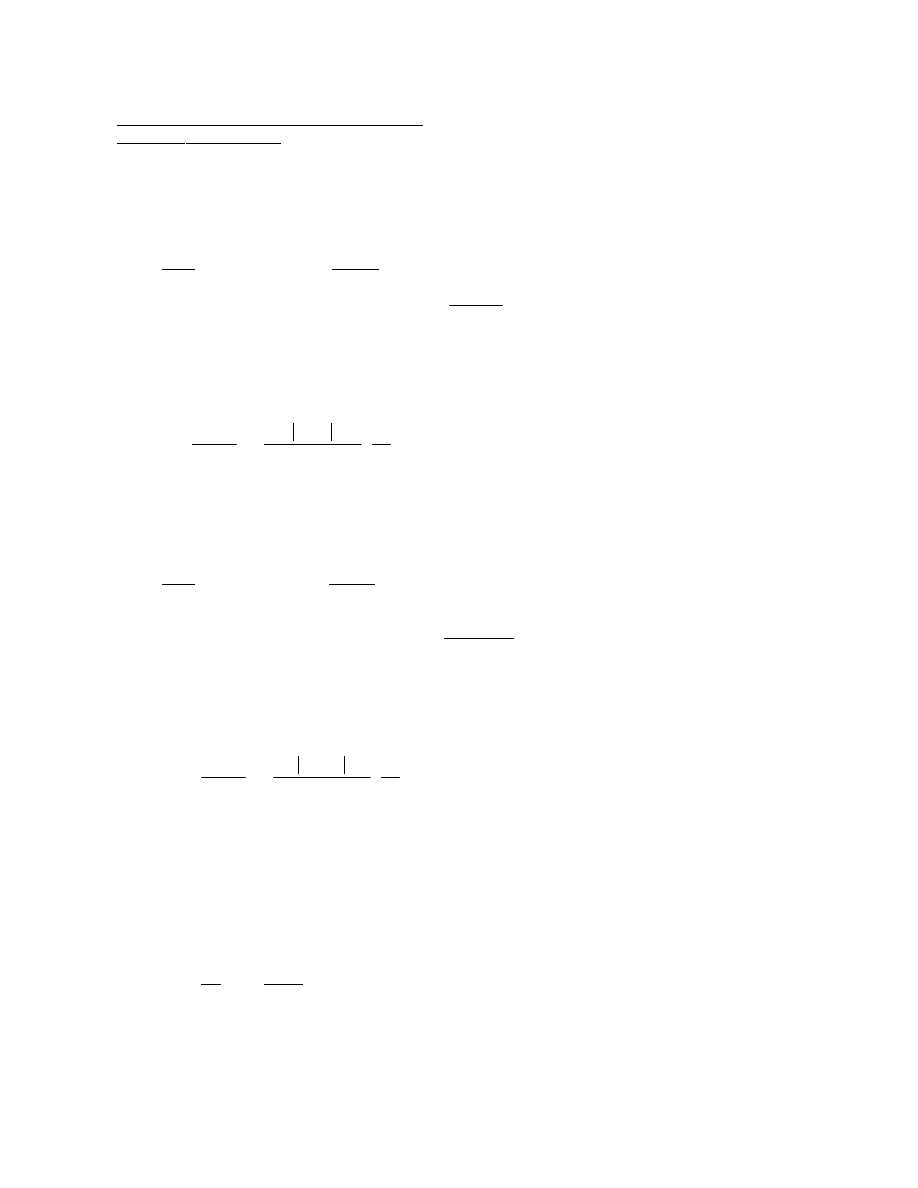
The enclosed area of the composite box is computed to be A
o
= 60.8 ft
2
.
f
v
=
T
2A
o
t
fc
=
1160
−
2 60.8
(
) 0.625
(
)
1
12
1.27
=
ksi
f
v
= 0.24 1.27
+
(
)
1.51
=
ksi
Compute the nominal flexural resistance for the bottom flange at the strength limit state according to
Article 6.11.8 for sections in negative flexure.
First, determine
λ
f
, the slenderness ratio for the compression flange.
Eq (6.11.8.2.2-4)
λ
f
=
b
fc
t
fc
=
81
0.625
129.6
=
where b
fc
is the flange width between webs measured in inches
Girder Stress Check Section 2-2 G2 Node 20.3
Strength - Bottom Flange
Check the compressive resistance of the unstiffened bottom flange directly across from the flange stiffener
termination according to the provisions of Article 6.11.8.2.2.
Compute the St. Venant torsional shear stress in the bottom flange due to the noncomposite loads.
Load
Torque
Steel
1.25(-36)
= -45 k-ft
All values are from Table C3
Deck
1.25(-125)
= -156 k-ft
Total Factored NC DL Torque
= -201 k-ft
Compute the bottom flange shear stress due to the noncomposite loads.
The enclosed area of the noncomposite box is computed to be A
o
= 55.0 ft
2
.
f
v
=
T
2A
o
t
fc
=
201
−
2 55.0
(
) 0.625
(
)
1
12
0.24
=
ksi
Eq (6.11.8.2.2-6)
where: T = torque; A
o
= enclosed area of box; t
fc
= flange thickness
Compute the St. Venant torsional shear stress in the bottom flange due to the composite loads.
Load
Torque
SupImp DL
1.25(-58)
= -73 k-ft
All values are from Table C3
FWS
1.50(-76)
= -114 k-ft
LL + IM
1.75(-556)
= -973 k-ft
Total Factored Comp. DL Torque
= -1,160 k-ft
Compute the bottom flange shear stress due to the composite loads.
D-51
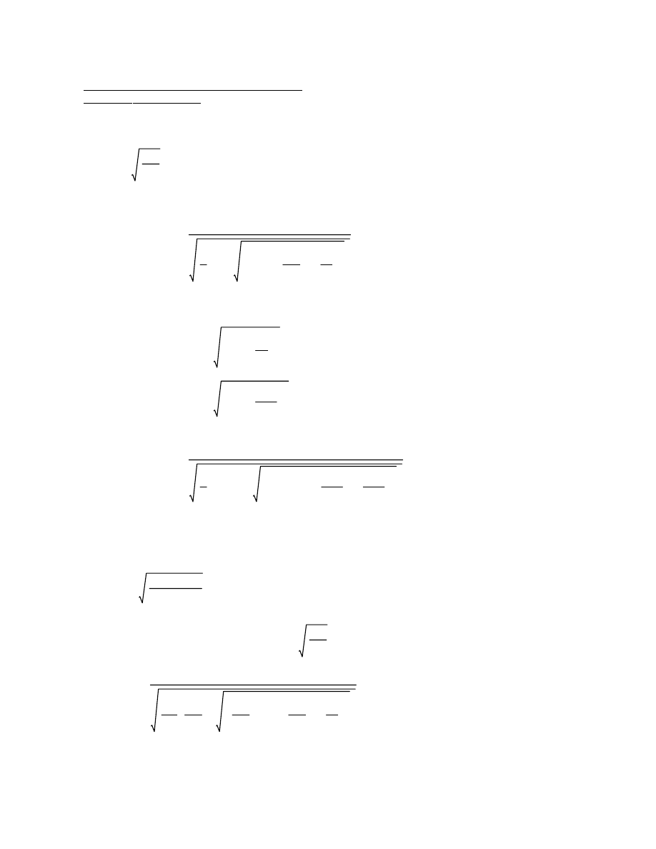
Eq (6.11.8.2.2-9)
1.23
1
1.2
F
yr
F
yc
F
yr
F
yc
2
4
f
v
F
yc
2
k
k
s
2
+
+
R
2
=
R
2
k E
F
yc
Determine if
λ
f
is less than or greater than
<
λ
f
= 129.6
0.57
4.0 29000
(
)
50
27.5
=
k = plate-buckling coefficient for uniform normal stress = 4.0
k
s
= plate-buckling coefficient for shear stress = 5.34
0.57
1
2
0.999
0.999
2
4
1.51
50
2
4.0
5.34
2
+
+
0.57
=
R
1
=
1
3
1.51
50
2
−
0.999
=
=
Eq (6.11.8.2.2-5)
1
3
f
v
F
y
2
−
∆ =
Compute
∆ according to Eq (6.11.8.2.2-5).
Eq (6.11.8.2.2-8)
0.57
1
2
∆
∆
2
4
f
v
F
yc
2
k
k
s
2
+
+
R
1
=
where:
R
1
k E
F
yc
Determine the equation used to compute the nominal flexural resistance.
Girder Stress Check Section 2-2 G2 Node 20.3
Strength - Bottom Flange
D-52
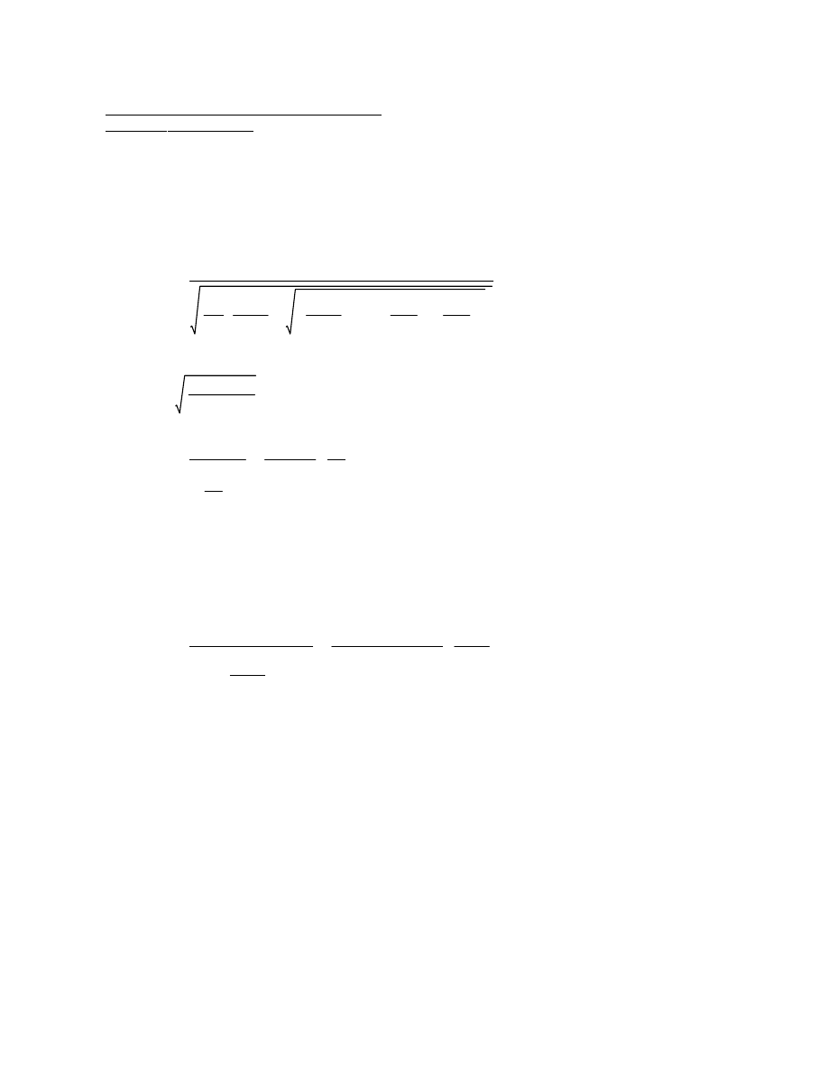
Therefore, the longitudinal flange stiffener may be discontinued at the field splice.
|-3.22| ksi < 1.0(6.01) = 6.01 ksi OK
Eq (6.11.8.1.1-1)
f
bu
φ
f
F
nc
≤
From Table D-1, the computed factored compressive stress in the bottom flange for strength = -3.22 ksi.
ksi
0.9 29000
(
) 1.0
(
) 4.0
(
)
81
0.625
2
1.0
(
) 1.51
(
)
2
4.0
(
)
0.9 29000
(
) 5.34
(
)
2
81
0.625
2
−
6.01
=
F
nc
=
R
b
is determined using the provisions of 6.10.1.10.2. Since this section is composite, is
in positive flexure and satisfies the web proportioning limits of Article 6.10.2.1, R
b
is
taken as 1.0.
where:
Eq (6.11.8.2.2-3)
0.9E R
b
k
b
fc
t
fc
2
R
b
f
v
2
k
0.9E k
s
2
b
fc
t
fc
2
−
F
nc
=
< 129.6 therefore, use Eq (6.11.8.2.2-3) for the calculation of F
nc
1.23
4.0 29000
(
)
50
59.2
=
1.23
1
1.2
29.95
50
29.95
50
2
4
1.51
50
2
4.0
5.34
2
+
+
1.23
=
R
2
=
ksi
0.999
0.4
−
(
)50
29.95
=
=
Eq (6.11.8.2.2-7)
∆
0.4
−
(
)F
yc
F
yw
≤
F
yr
=
where:
Girder Stress Check Section 2-2 G2 Node 20.3
Strength - Bottom Flange
D-53

Article 6.13.6.1.4a states that the factored flexural resistance of the section at the point of the splice at
the strength limit state must satisfy the applicable provisions of Article 6.10.6.2.
Eq (6.13.2.2-2)
where
φ is specified in Article 6.5.4.2
R
r
=
φR
n
The factored resistance, R
r
of a bolted connection at the strength limit state shall be taken as:
Strength
k/bolt
1.0
(
) 0.50
(
) 2
( ) 39
(
)
39
=
R
n
=
N
s
= number of slip planes per bolt
P
t
= minimum required bolt tension specified in Table 6.13.2.8-1 (kips)
K
h
= hole size factor specified in Table 6.13.2.8-2
K
s
= surface condition factor specified in Table 6.13.2.8-3
where:
Eq (6.13.2.8-1)
R
n
= K
h
K
s
N
s
P
t
The nominal slip resistance of a bolt in a slip-critical connection is taken as:
where: R
n
= the nominal resistance as specified in Article 6.13.2.8
R
r
= R
n
For slip-critical connections, the factored resistance, R
r
, of a bolt at the Service II Load Combination is
taken as:
Slip Resistance (Article 6.13.2.8)
Service and Constructibility
Use a Class B surface condition for unpainted blast-cleaned surfaces. Bolts are in double shear and
threads are not permitted in the shear planes.
Use 7/8 in. diameter ASTM A 325 bolts. Table 6.13.2.4.2-1 provides a standard hole size of 15/16 in. for a
7/8 in. diameter bolt.
Bolt capacities (Articles 6.13.2.3.1 and 6.4.3)
Design the bolted field splice at this section according to the provisions of Article 6.13.6.
Bolted Splice Design Section 2-2 G2 Node 20.3
Design Action Summary and Section Information
D-54

k/bolt
0.8 65.81
(
)
52.65
=
R
r
=
where:
φ
bb
is from Article 6.5.4.2
R
r
=
φ
bb
R
n
k/bolt
1.2 1.5
(
) 0.5625
(
) 65
(
)
65.81
=
R
n
=
In this case, the end distance is 2.0 in. creating a clear end distance of 1.5 in. which less than 2.0d,
therefore, Eq (6.13.2.9-2) applies. The nominal bolt resistance for the end row of bolts is:
d = nominal diameter of the bolt (in.)
L
c
= clear distance between holes or between the hole and the end of the member
in the direction of the applied force (in.)
t = thickness of the connected material (in.)
F
u
= tensile resistance of the connected material specified in Table 6.4.1-1 (ksi)
where:
Eq (6.13.2.9-2)
R
n
= 1.2L
c
tF
u
If either the clear distance between holes is less than 2.0d, or the clear end distance is less than 2.0d:
Eq (6.13.2.9-1)
R
n
= 2.4dtF
u
With bolts spaced at a clear distance between holes not less than 2.0d and with a clear end distance
not less than 2.0d:
For standard holes, the nominal resistance of interior and end bolt holes at the strength limit state, R
n
, is
taken as:
Bearing Resistance (Article 6.13.2.9)
k/bolt
0.8 69.2
(
)
55.4
=
R
r
=
where
φ
s
is the shear resistance factor from Article 6.5.4.2
R
r
=
φ
s
R
n
k/bolt
0.48 0.601
(
) 120
(
) 2
( )
69.2
=
R
n
=
Eq (6.13.2.7-1)
R
n
= 0.48A
b
F
ub
N
s
The nominal shear resistance, R
n
, of a high-strength bolt at the strength limit state where the length
between extreme fasteners measured parallel to the line of action of the force is less than 50.0 in. and
the threads are excluded from the shear plane is as follows:
Shear Resistance (Article 6.13.2.7)
Bolted Splice Design Section 2-2 G2 Node 20.3
Design Action Summary and Section Information (continued)
D-55

The tensile bolt resistance is not used in this example.
k/bolt
0.76 0.601
(
) 120
(
)
54.8
=
T
n
=
Eq (6.13.2.10.2-1)
T
n
= 0.76A
b
F
ub
The nominal tensile resistance of a bolt, T
n
, independent of any initial tightening force shall be taken as:
Tensile Resistance (Article 6.13.2.10)
k/bolt
0.8 76.78
(
)
61.42
=
R
r
=
Eq (6.13.2.9-1)
k/bolt
2.4 0.875
(
) 0.5625
(
) 65
(
)
76.78
=
R
n
=
The nominal bolt resistance for the interior rows is computed as:
Bolted Splice Design Section 2-2 G2 Node 20.3
Design Action Summary and Section Information (continued)
D-56

k/bolt
176
−
12
14.67
=
F
Long
vert
=
Compute the force in each bolt resulting from the vertical bending stress.
kips
11.13
−
10.87
−
2
16.0
(
)
176
−
=
F
top
=
Compute the force in the top flange using the average vertical bending stress in the flange. The gross
section of the flange is used to check for slip.
f
top web
= -10.87 ksi
f
top flg
= -11.13 ksi
The factored vertical bending stresses for steel and Cast #1 are taken from Table D-2.
k-ft (unfactored from Table D-3)
1
−
15
−
(
)
+
16
−
=
Lateral flange moment =
k-ft (unfactored from Table D-3)
462
2749
+
3211
=
Moment =
A
b
= area of one bolt (in
2
)
where:
= 342 A
b
in
4
A
b
2 3
( ) 3.0
2
6.0
2
+
(
)
2 4
( ) 3.0
2
( )
+
I
p
=
Compute the polar moment of inertia of the top flange bolt pattern shown in Figure D-5.
Article 6.13.6.1.4c requires that lateral bending effects in discretely braced top flanges of tub sections be
considered in the design of bolted flange splices. Lateral flange bending must be considered for the top
flanges of tub girders prior to hardening of the deck. To account for the effects of lateral flange bending,
the flange splice bolts will be designed for the combined effects of shear and moment using the traditional
elastic vector method. The shear on the bolts is caused by the flange force calculated from the average
vertical bending stress in the flange and the moment on the bolts is caused by the lateral flange bending.
Since Cast #1 causes a larger positive moment than the entire deck, Steel + Cast #1 controls.
Constructibility: Load factor = 1.25 (Article 3.4.2).
Constructibility
Article 6.13.6.1.4a requires that high-strength bolted connections designated as slip critical be
proportioned to prevent slip under Load Combination Service II. In addition, bearing, shear, and tensile
resistance at the applicable strength limit state load combinations must be provided. Article 6.13.6.1.4a
also requires that high-strength bolted connections be proportioned to prevent slip for constructibility.
Bolted Splice Design Section 2-2 G2 Node 20.3
Constructibility - Top Flange
D-57

R
u
= 19.0 k/bolt < R
r
= 39 k/bolt OK
R
u
R
r
≤
Check
k/bolt
2.11
2
18.88
2
+
19
=
Σ
F
=
Compute the resultant force on the critical bolt.
k/bolt
16
−
3.0
(
)
342
12
(
) 1.25
(
)
2.11
=
F
Trans
=
Compute the transverse component of force in the critical bolt.
k/bolt
14.67
4.21
+
18.88
=
F
Long tot
=
Therefore,
k/bolt
16
−
6.0
(
)
342
12
(
) 1.25
(
)
4.21
=
F
Long lat
=
Compute the longitudinal component of force in the critical bolt due to the lateral flange moment.
Bolted Splice Design Section 2-2 G2 Node 20.3
Constructibility - Top Flange (continued)
D-58

k/bolt
77.4 36.25
(
)
19859
0.14
=
F
Long M
=
Compute the longitudinal component of force in the critical bolt due to the factored moment.
k-in
17.2 2.25
2.25
+
(
)
77.4
=
M =
Compute the factored moment in the bottom flange due to the torsional shear. Assume the shear is
applied at the centerline of the splice (i.e. at the juncture of the two flange plates).
kips
224
−
2 55.0
(
)
81
12
1.25
(
)
17.2
=
=
T
2A
o
b
f
V =
Compute the factored St. Venant torsional shear in the bottom flange. From Table D-3 , the unfactored
torque due to Steel plus Cast #1 = -36 + (-188) = -224 k-ft. The enclosed area of the noncomposite box,
A
o
, is computed to be 55.0 ft
2
.
I
p
= A
b
[2(20)(2.25)
2
+ 2(2)(2.5
2
+ 6.25
2
+ 10
2
+ 13.75
2
+ 17.5
2
+ 21.25
2
+ 25
2
+ 28.75
2
+ 32.5
2
+ 36.25
2
)] = 19,859A
b
in
4
Compute the polar moment of inertia of the bottom flange bolt pattern shown in Figure D-5.
To account for the effects of the St. Venant torsional shear in the bottom flange, the flange splice bolts
will again be designed for the combined effects of shear and moment using the traditional elastic vector
method, as illustrated below.
kips
9.58
9.42
+
2
51.88
(
)
493
=
F
bot
=
Compute the force in the bottom flange from the average constructibility vertical bending stress. The
gross section of the flange is used to check for slip.
f
bot web
= 9.42 ksi
f
bot flg
= 9.58 ksi
Since Cast #1 causes a larger positive moment than the entire deck, Steel + Cast #1 controls
constructibility. Load factor = 1.25 (Article 3.4.2). The factored vertical bending stresses are taken from
Table D-2.
Bolted Splice Design Section 2-2 G2 Node 20.3
Constructibility - Bottom Flange
D-59
R
u
= 12.47 k/bolt < R
r
= 39 k/bolt OK
R
u
R
r
≤
Check
k/bolt
12.46
2
0.44
2
+
12.47
=
Σ
F
=
Compute the resultant force in the critical bolt.
k/bolt
0.009
0.43
+
0.44
=
F
Trans tot
=
k/bolt
17.2
40
0.43
=
F
v
=
Compute the force in each bolt resulting from the torsional shear.
k/bolt
77.4 2.25
(
)
19859
0.009
=
F
Trans
=
Compute the transverse component of force in the critical bolt.
k/bolt
0.14
12.32
+
12.46
=
F
Long tot
=
Therefore,
k/bolt
493
40
12.32
=
F
Long
vert
=
Compute the force in each bolt resulting from the vertical bending stress.
Bolted Splice Design Section 2-2 G2 Node 20.3
Constructibility - Bottom Flange (continued)
D-60
The effective width of the top flange is computed as:
(b
f
)
eff
=
A
e
t
=
12
1.0
12
=
in.
Section properties computed using the effective top flange width are used to calculate the vertical
bending stresses in the flange at the splice for strength whenever the top flange is subjected to
tension. The gross area is used for the bottom flange since it is in compression.
Similarly, the effective area of the bottom flange is computed as:
A
n
=
83.0
20 0.875
0.125
+
(
)
−
[
] 0.625
(
)
39.4
=
in
2
A
g
= 83.0
(
) 0.625
(
)
51.9
=
in
2
A
e
=
0.8 65
(
)
0.95 50
(
)
39.4
(
)
43.13
=
in
2
< 51.9 in
2
Therefore,
A
e
= 43.13 in
2
Bolted Splice Design Section 2-2 G2 Node 20.3
Strength - Top and Bottom Flange
The effective area of the top flange is computed from Article 6.13.6.1.4c as follows:
A
e
=
φ
u
F
u
φ
y
F
yt
A
n
A
g
≤
Eq (6.13.6.1.4c-2)
where:
F
u
= minimum tensile resistance of the tension flange, ksi
F
yt
= minimum yield resistance of the tension flange, ksi
A
n
= net area of the flange calculated as specified in Article 6.8.3, in
2
= 16.0 4 0.875
0.125
+
(
)
−
[
] 1.0
(
)
12
=
in
2
A
g
= gross area of the flange, in
2
= 16.0
(
) 1.0
(
)
16
=
in
2
A
e
=
0.8 65
(
)
0.95 50
(
)
12
(
)
13.14
=
in
2
< 16 in
2
D-61

ksi (T)
1.25 2403
(
) 37.52
(
)
179050
1.25 326
(
)
1.5 428
(
)
+
[
] 55.63
(
)
338310
+
1.75 5264
(
) 68.90
(
)
456064
+
12
26.32
=
F
bot flg
=
ksi (C)
1.25 2403
(
) 41.29
(
)
179050
1.25 326
(
)
1.5 428
(
)
+
[
] 23.18
(
)
338310
+
1.75 5264
(
) 9.91
(
)
456064
+
−
12
11.58
−
=
F
top flg
=
Positive live load bending case
ksi (C)
1.25 2403
(
) 37.52
(
)
179050
1.25 326
(
)
1.5 428
(
)
+
[
] 35.79
(
)
179740
+
1.75 3087
−
(
) 35.79
(
)
179740
+
12
2.85
−
=
F
bot flg
=
ksi (T)
1.25 2403
(
) 41.29
(
)
179050
1.25 326
(
)
1.5 428
(
)
+
[
] 43.02
(
)
179740
+
1.75 3087
−
(
) 43.02
(
)
179740
+
−
12
4.19
=
F
top flg
=
Negative live load bending case
Using the effective section properties (from separate calculations), calculate the average factored bending
stress in the top and bottom flange at the Strength limit state for both the positive and the negative live
load bending conditions.
Calculate the factored vertical bending stress in the top and bottom flange mid-thicknesses at the
strength limit state for both the positive and negative live load bending conditions. The longitudinal
component of the top flange bracing area is again included in the effective section properties. The
contribution of deck reinforcement is not included in the section properties at this section. The smaller
section is to be used to design the splice, therefore, the longitudinal flange stiffener is not included. The
provisions of Article 4.5.2.2 are followed to determine which composite section (cracked or uncracked) to
use.
Section properties from Table C5 are computed using the effective bottom flange thickness are used to
calculate the vertical bending stresses in the flange at the splice for strength whenever the bottom flange
is subjected to tension. The gross area is used for the top flange in this case. For flanges and splice
plates subjected to compression, net section fracture is not a concern and the effective area is taken
equal to the gross area.
It is more advantageous to determine the effective thickness for the bottom flange and not the effective
width in order to maintain the web slopes.
in.
43.13
83.0
0.52
=
=
A
e
b
f
(t
f
)
eff
=
For the bottom flange of the box, an effective flange thickness will be computed. The effective thickness
of the bottom flange is computed as:
Bolted Splice Design Section 2-2 G2 Node 20.3
Strength - Top and Bottom Flange (continued)
D-62
where
α is again taken as 1.0. For a continuously braced top flange in tension, α should also be taken
equal to 1.0.
Eq (6.13.6.1.4c-3)
R
cf
f
ncf
R
h
0.75
αφ
f
F
y
≥
F
ncf
=
The minimum design stress for the noncontrolling (top) flange for this case is specified in Article
6.13.6.1.4c as:
kips (T)
38.16 43.13
(
)
1646
=
P
cf
=
The minimum design force for the controlling (bottom) flange, P
cf
, is taken equal to F
cf
times the smaller
effective flange area, A
e
, on either side of the splice. The area of the smaller flange is used to ensure that
the design force does not exceed the strength of the smaller flange. In this case, the effective flange
areas are the same on both sides of the splice.
ksi; therefore, use 38.16 ksi
0.75 1.0
(
) 1.0
(
) 50
(
)
37.5
=
0.75
αφ
f
F
yf
=
ksi
26.32
1.0
1.0 1.0
(
) 50
(
)
+
2
38.16
=
F
cf
=
f
cf
is the maximum flexural stress due to the factored loads at the mid-thickness of the controlling flange
at the point of splice. The hybrid factor R
h
is taken as 1.0 when F
cf
does not exceed the specified
minimum yield resistance of the web.
α is taken as 1.0, except that a lower value equal to (F
n
/F
yf
) may
be used for flanges where F
n
is less than F
yf
.
Eq (6.13.6.1.4c-1)
f
cf
R
h
αφ
f
F
yf
+
2
0.75
αφ
f
F
yf
≥
F
cf
=
Separate calculations (similar to subsequent calculations) show that the positive live load bending case is
critical. For this loading case, the bottom flange is the controlling flange since it has the largest ratio of
the flexural stress to the corresponding critical flange stress. Article 6.13.6.1.4c defines the design
stress, F
cf
, for the controlling flange as follows:
An acceptable alternative to the preceding calculation is to calculate the average factored vertical bending
stress in both flanges for both live load bending conditions using the appropriate gross section properties.
Then, for the flange in tension, multiply the calculated average stress times the gross area, A
g
, of the
flange, and then divide the resulting force by the effective area, A
e
, of the flange to determine an adjusted
average tension-flange stress. Then, for the critical live load bending condition, use the adjusted average
stress in the tension flange and the calculated average stress in the compression flange to determine
which flange is the controllong flange, as defined below.
Bolted Splice Design Section 2-2 G2 Node 20.3
Strength - Top and Bottom Flange (continued)
D-63
Load
Torque
Steel
1.25(-36)
= -45 k-ft
Deck
1.25(-125)
= -156 k-ft
Noncomposite torque
-201 k-ft
Compute the factored St. Venant torsional shear in the bottom flange at the strength limit state. Warping
torsion is ignored since it is assumed in this example that the spacing of the internal bracing is sufficient
to limit the warping stress to 10 percent of the vertical bending stress at the strength limit state (Article
6.7.5.3). Further, the specifications do not require warping to be considered in the design of bolted box
flange splices at the strength limit state. From Table D-3, the torques are as follows:
Bottom Flange
Since a fill plate is not required for the top flange splice, no reduction in the bolt design shear resistance
is required per the requirements of Article 6.13.6.1.5.
k/bolt < 55.4 k/bolt OK
600
12
50
=
bolts, use 12 bolts
600
55.4
10.8
=
=
F
ncf
A
e
R
r
No. bolts required =
St. Venant torsional shears are not considered in the top flanges of tub girders. Lateral flange bending in
the top flange is also not considered after the deck has hardened and the section is closed. Therefore:
Top Flange
where the effective flange area, A
e
, is taken equal to the smaller gross flange area, A
g
, on either side of
the splice since the flange is subjected to compression. In this case, the gross flange areas are the
same on both sides of the splice.
kips (C)
37.5
(
) 16.0
(
) 1.0
(
)
600
=
P
ncf
= F
ncf
A
e
=
The minimum design force for the noncontrolling flange, P
ncf
, is computed as:
ksi (controls)
0.75 1.0
(
) 1.0
(
) 50
(
)
37.5
=
0.75
αφ
f
F
yf
=
ksi
1.45
11.58
−
1.0
16.79
=
=
R
cf
f
ncf
R
h
f
ncf
is the factored vertical bending stress in the noncontrolling flange at the splice concurrent with f
cf
.
38.16
26.32
1.45
=
=
F
cf
f
cf
R
cf
=
Bolted Splice Design Section 2-2 G2 Node 20.3
Strength - Top and Bottom Flange (continued)
D-64
105.7 2.25
2.25
+
(
)
475.7
=
k-in
Compute the longitudinal component of force in the critical bolt due to the factored moment.
F
Long M
=
475.7 36.25
(
)
19859
0.87
=
k/bolt
Compute the force in each bolt due to the minimum design force, P
cf
.
F
L
=
1646
40
41.1
=
k/bolt
Therefore,
F
Long tot
= 0.87 41.1
+
42
=
k/bolt
Compute the transverse component of force in the critical bolt.
F
Trans
=
475.7 2.25
(
)
19859
0.05
=
k/bolt
Bolted Splice Design Section 2-2 G2 Node 20.3
Strength - Top and Bottom Flange (continued)
SupImp DL
1.25(-58)
= -73 k-ft
FWS
1.50(-76)
= -114 k-ft
LL + IM
1.75(-517)
= -905 k-ft
Composite torque
-1,092 k-ft
V =
T
2A
o
b
f
V
noncomp
=
201
−
2 55.0
(
)
81
12
12.3
=
kips
V
comp
=
1092
−
2 60.8
(
)
81
12
60.6
=
kips
V
total
= 12.3 60.6
+
72.9
=
kips
The total torsional shear is then factored up by R
cf
= 1.45 (see earlier calculations) to be consistent with
the computation of F
cf
and P
cf
.
V
fact
= 72.9 1.45
(
)
105.7
=
kips
Compute the factored moment in the bottom flange due to the torsional design shear. Assume the shear
is applied at the centerline of the splice (i.e. at the juncture of the two flange plates).
M =
D-65
Bolted Splice Design Section 2-2 G2 Node 20.3
Strength - Top and Bottom Flange (continued)
Compute the force in each bolt resulting from the factored torsional design shear.
F
v
=
105.7
40
2.64
=
k/bolt
F
Trans tot
= 2.64 0.05
+
2.69
=
k/bolt
Compute the resultant force on the critical bolt.
Σ
F
=
42
2
2.69
2
+
42.09
=
k/bolt
Check R
u
R
r
≤
R
u
= 42.09 k/bolt < R
r
= 55.4 k/bolt OK
Note that a fill plate is also not required for the bottom flange splice. Therefore, no reduction in the bolt
design shear resistance is necessary.
D-66

k-ft
93.75
3
2
4.5
2
+
1
12
29.3
=
M
v
= Ve =
Compute the moment, M
v
, due to the eccentricity of the factored shear about the centroid of the
connection (refer to the web bolt pattern in Figure D-6).
kips
17
−
58
−
(
) 1.25
(
)
93.75
−
=
V =
From Table D-3, compute the factored vertical shear at the splice (bending plus torsional shear in the
critical web) due to Steel plus Cast #1.
Constructibility
As stated previously, Article 6.13.6.1.4a requires that high-strength bolted connections be proportioned to
prevent slip for constructibility. Article 6.13.6.1.4b requires that bolted web splices be designed to prevent
slip under the most critical combination of the design actions at service load, Load Combination Service II.
in
4
20 2
( )
12
3.75
2
20
2
1
−
(
)
3
2
2
2
1
−
(
)
+
18793
=
I
p
=
For n = 20; m = 2; s = 3.75 in.; g = 3 in.,
m = number of vertical rows of bolts
n = number of bolts in one vertical row
s = vertical pitch, in.
g = horizontal pitch, in.
where:
Eq (C6.13.6.1.4b-3)
nm
12
s
2
n
2
1
−
(
)
g
2
m
2
1
−
(
)
+
I
p
=
Compute the polar moment of inertia of the web bolts about the centroid of the bolt group on one side of
the connection.
A pattern of two rows of 7/8 in. bolts spaced vertically at 3.75 in. will be tried for the web splice. There
are 40 bolts on each side of the web splice. The pattern is shown in Figure D-6 . Although not illustrated
here, the number of bolts in the web splice could be decreased by spacing a group of bolts closer to the
mid-depth of the web (where the flexural stress is relatively low) at the maximum spacing specified for
sealing (Article 6.13.2.6.2), and by spacing the remaining two groups of bolts near the top and bottom of
the web at a closer spacing. Note that there is 4.625 in. between the inside of the flanges and the first
bolt to provide sufficient assembly clearance. In this example, the web splice is designed under the
conservative assumption that the maximum moment and shear at the splice will occur under the same
loading condition.
Bolted Splice Design Section 2-2 G2 Node 20.3
Constructibility - Web
D-67
kips
Eq (C6.13.6.1.4b-2)
The total moment on the web splice is computed as:
M
tot
= M
v
+ M
uw
= 29.3 487
+
516
=
k-ft
Compute the in-plane bolt force due to the factored vertical shear.
F
s
=
V
N
b
=
93.75
40
2.34
=
k/bolt;
2.34
cos 14.0
2
π
360
2.4
=
k/bolt
Compute the in-plane bolt force due to the horizontal force resultant.
F
H
=
H
uw
N
b
=
32.9
−
40
0.82
=
k/bolt
Bolted Splice Design Section 2-2 G2 Node 20.3
Constructibility - Web (continued)
Determine the portion of the design moment resisted by the web, M
uw
, and the design horizontal force
resultant in the web, H
uw
, using equations similar to those provided in Article C6.13.6.1.4b for Load
Combination Service II. M
uw
and H
uw
are assumed to be applied at the middepth of the web for
designing the web splice plates and their connections. Using the results from earlier calculations (Table
D-2), the average factored vertical bending stress in the top flange for Steel plus Cast #1 is computed as:
F
cf
=
11.13
−
10.87
−
2
11
−
=
ksi
The average factored vertical bending stress in the bottom flange is (see Table D-2)
f
ncf
=
9.58
9.42
+
2
9.5
=
ksi
Using these stresses (set R
h
and R
cf
equal to 1.0)
M
uw
=
t
w
D
2
12
R
h
F
cf
R
cf
f
ncf
−
=
0.5625 78
(
)
2
12
1.0 11.0
−
(
)
1.0 9.5
(
)
−
1
12
487
=
k-ft
Eq (C6.13.6.1.4b-1)
H
uw
=
t
w
D
2
R
h
F
cf
R
cf
f
ncf
+
(
)
=
0.5625 78
(
)
2
1.0 11.0
−
(
)
1.0 9.5
(
)
+
[
]
32.9
−
=
D-68
F
r
= 12.24 k/bolt < R
r
= 39 k/bolt OK
k/bolt
2.4
0.48
+
(
)
2
0.82
11.08
+
(
)
2
+
12.24
=
=
F
s
F
Mv
+
(
)
2
F
H
F
Mh
+
(
)
2
+
F
r
=
Compute the resultant in-plane bolt force.
k/bolt
487 12
(
) 35.625
(
)
18793
11.08
=
=
M
tot
y
I
p
F
Mh
=
k/bolt
0.47
cos 14.0
2
π
360
0.48
=
k/bolt;
487 12
(
)
3
2
18793
0.47
=
=
M
tot
x
I
p
F
Mv
=
Compute the in-plane horizontal and vertical components of the force on the extreme bolt
due to the total moment on the splice.
Bolted Splice Design Section 2-2 G2 Node 20.3
Constructibility - Web (continued)
D-69

Eq (6.10.9.3.2-7)
5
5
196
80.4
2
+
5.84
=
=
5
5
d
o
D
2
+
k =
80.4
0.5625
143
=
=
D
t
w
Determine which equation is to be used to compute the ratio of the shear-buckling resistance to the
shear yield resistance, C.
Eq (6.10.9.3.2-3)
V
p
= 0.58F
yw
Dt
w
where:
Eq (6.10.9.3.2-2)
V
p
C
0.87 1
C
−
(
)
1
d
o
D
2
+
+
V
n
=
The nominal shear resistance, V
n
, is taken as:
< 2.5, the provisions of Article 6.10.9.3.2 may be used.
2 80.4
(
) 0.5625
(
)
81 0.625
(
)
16 1
( )
+
[
]
1.4
=
Eq (6.10.9.3.2-1)
2Dt
w
b
fc
t
fc
b
ft
t
ft
+
(
)
2.5
≤
Article 6.10.9.3.2 is used for the nominal shear resistance of an interior web panel. The section along the
entire panel must be proportioned according to Eq (6.10.9.3.2-1).
Separate calculations indicate that transverse stiffeners are required for this web thickness, therefore,
use Article 6.10.9.3.
Try a stiffener spacing equal to the cross-frame spacing, d
o
= 196 in.
Compute the nominal shear resistance of the 0.5625 in. thick web at the splice according to the
provisions of Articles 6.10.9.2 and 6.10.9.3 for unstiffened and stiffened webs, respectively.
kips
1.25 17
−
69
−
12
−
(
)
1.5 16
−
(
)
+
1.75 85
−
(
)
+
295
−
=
V
u
=
From Table D-3, the factored vertical shear at the splice (bending plus torsional shear in the critical web
at the strength limit state) is computed as:
Determine the vertical design shear, V
uw
, for the web splice for strength according to the provisions of
Article 6.13.6.1.4b.
Bolted Splice Design Section 2-2 G2 Node 20.3
Strength - Web
D-70
V
n
= 1312 0.26
0.87 1
0.26
−
(
)
1
196
80.4
2
+
+
662
=
kips
φ
v
V
n
= 1.0(662) = 662 kips >
V
ui
=
295
cos 14.0
2
π
360
304
=
kips OK
Eq (6.10.9.1-1)
Therefore, according to Article 6.13.6.1.4b, since V
u
< 0.5
φ
v
V
n
:
V
uw
= 1.5V
u
= 1.5 304
(
)
456
=
kips
Eq (6.13.6.1.4b-1)
The moment, M
uv
, due to the eccentricity, e, of V
uw
from the centerline of the splice to the centroid of the
web splice bolt group is computed as follows (refer to web bolt pattern in Figure D-6):
M
uv
= V
uw
e
M
uv
= 456
3
2
4.5
2
+
1
12
143
=
k-ft
Bolted Splice Design Section 2-2 G2 Node 20.3
Web - Strength (continued)
1.12
Ek
F
yw
= 1.12
29000 5.84
(
)
50
65
=
< 143
1.40
Ek
F
yw
= 1.40
29000 5.84
(
)
50
81
=
< 143
Therefore, use Eq (6.10.9.3.2-6).
C =
1.57
D
t
w
2
Ek
F
yw
=
1.57
80.4
0.5625
2
29000 5.84
(
)
50
0.26
=
Eq (6.10.9.3.2-6)
V
p
= 0.58F
yw
Dt
w
= 0.58 50
(
) 80.4
(
) 0.5625
(
)
1312
=
kips
D-71
Eq (C6.13.6.1.4b-2)
The total moment on the web splice is computed as:
M
tot
= M
uv
+ M
uw
= 143
1306
+
1449
=
k-ft
Compute the in-plane bolt force due to the vertical design shear.
F
s
=
V
uw
N
b
=
456
40
11.4
=
k/bolt;
11.4
cos 14.0
2
π
360
11.75
=
k/bolt
Compute the in-plane bolt force due to the horizontal design force resultant.
F
H
=
H
uw
N
b
=
443
40
11.1
=
k/bolt
Bolted Splice Design Section 2-2 G2 Node 20.3
Web - Strength (continued)
Determine the portion of the design moment resisted by the web, M
uw
, and the design horizontal force
resultant in the web, H
uw
, according to the provisions of Article C6.13.6.1.4b. M
uw
and H
uw
are applied
at the middepth of the web. Separate calculations indicate that the positive live load bending condition
controls.
As computed earlier (pages D-62 and D-63) for the positive live load bending case:
f
cf
= 26.32 ksi
F
cf
= 38.16 ksi
f
ncf
= -11.58 ksi
R
cf
= 1.45 ksi
From the equations in Article C6.13.6.1.4b:
M
uw
=
t
w
D
2
12
R
h
F
cf
R
cf
f
ncf
−
=
0.5625 78
(
)
2
12
1.0 38.16
(
)
1.45 11.58
−
(
)
−
1
12
1306
=
k-ft
Eq (C6.13.6.1.4b-1)
H
uw
=
t
w
D
2
R
h
F
cf
R
cf
f
ncf
+
(
)
=
0.5625 78
(
)
2
1.0 38.16
(
)
1.45 11.58
−
(
)
+
[
]
469
=
kips
D-72
F
res
= 46.0 k/bolt < R
r
= 55.4 k/bolt OK
k/bolt
11.75
1.43
+
(
)
2
11.1
32.97
+
(
)
2
+
46
=
=
F
s
F
Mv
+
(
)
2
F
H
F
Mh
+
(
)
2
+
F
resultant
=
Compute the resultant in-plane bolt force.
k/bolt
1449 12
(
) 35.63
(
)
18793
32.97
=
=
M
tot
y
I
p
F
Mh
=
k/bolt
1.39
cos 14.0
2
π
360
1.43
=
k/bolt;
1449 12
(
)
3
2
18793
1.39
=
=
M
tot
x
I
p
F
Mv
=
Compute the in-plane horizontal and vertical components of the force on the extreme bolt due to the total
moment on the splice.
Bolted Splice Design Section 2-2 G2 Node 20.3
Web - Strength (continued)
D-73

in
3
2
0.375
(
)75.25
3
12
cos 14
2
π
360
2
75.25
2
cos 14
2
π
360
686.8
=
=
I
x
cos
2
θ
c
S
PL
=
in
2
2 0.375
(
) 75.25
(
)
56.44
=
A
g
=
According to Article 6.13.6.1.4b, check for flexural yielding on the gross section of the web splice plates
at the strength limit state. The flexural stress is limited to
φ
f
F
y
.
kips OK
0.8 65.81
(
)
52.65
=
F
resultant
= 46.0 kips <
φ
bb
R
n
=
The maximum resultant in-plane force on the extreme bolt was computed earlier (page D-73) for strength
to be:
Check bearing of the bolts on the connected material assuming the bolts have slipped and gone into
bearing. Since the bearing resistance of the web controls, the bearing resistance of the outermost hole in
the thinner web at the splice, calculated using the clear edge distance, will conservatively be checked
against the maximum resultant force acting on the extreme bolt in the connection. This check is
conservative since the resultant force acts in the direction of an inclined distance that is larger than the
clear edge distance. Should the bearing resistance be exceeded, it is recommended that the edge
distance be increased slightly in lieu of increasing the number of bolts or thickening the web. Another
option would be to calculate the bearing resistance based on the inclined distance, or else resolve the
resultant force in the direction parallel to the edge distance. In cases where the bearing resistance of the
web splice plates controls, the smaller of the clear edge or end distance on the splice plates can be used
to compute the bearing resistance of the outermost hole.
4 + 4(0.375) = 5.5 in. < 7.0
=
4
4t
+
7.0
≤
The maximum permissible spacing of the bolts for sealing =
Use nominal 0.375-in. thick splice plates. Fill plates are not required in this case.
Web Splice Plate Design
Bolted Splice Design Section 2-2 G2 Node 20.3
Splice Plates
D-74
< 7.5 in
2
OK
0.8 65
(
)
0.95 50
(
)
5.0
(
)
5.47
=
Inner plate:
< 8.0 in
2
OK
0.8 65
(
)
0.95 50
(
)
6.0
(
)
6.57
=
Outer plate:
in
2
2 6.0
2 0.875
0.125
+
(
)
−
[
] 0.625
5
=
Inner plate: A
n
=
in
2
16.0
4 0.875
0.125
+
(
)
−
[
] 0.5
(
)
6
=
Outer plate: A
n
=
Eq (6.13.6.1.4c-2)
φ
u
F
u
φ
y
F
yt
A
n
A
g
≤
A
e
=
The effective areas of the inner and outer splice plates are computed as:
As specified in Article 6.13.6.1.4c, the effective area, A
e
, of each splice plate is to be sufficient to prevent
yielding of each splice plate under its calculated portion of the minimum flange design force. For splice
plates subjected to compression, the effective area is equal to the gross area.
Try:
16 x 0.5 in. outer plate
Try:
2 - 6 x 0.625 in. inner plates
A
g
= 8.0 in
2
A
g
= 7.50 in
2
The width of the outside splice plate should be at least as wide as the width of the narrowest flange at
the splice. In this case, however, the width of the top flange is the same on either side of the splice.
Therefore;
Top Flange
Flange Splice Plate Design
Since the thickness of the two splice plates exceeds t
w
, say the shear resistance in the splice plates
is adequate.
ksi <
φ
f
F
y
= 1.0(50) = 50 ksi OK
143
1306
+
(
) 12
(
)
686.8
469
56.44
+
33.63
=
=
M
uv
M
uw
+
S
PL
H
uw
A
g
+
f =
Bolted Splice Design Section 2-2 G2 Node 20.3
Splice Plates (continued)
D-75
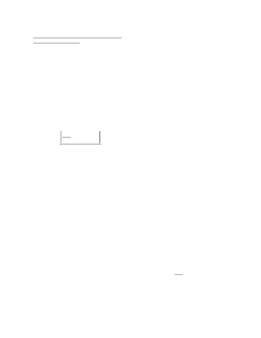
Outer plate
P
r
= 0.95 50
(
) 7.50
(
)
356
=
kips
Inner plates
or
P
r
=
φ
u
P
nu
=
φ
u
F
u
A
n
U
Eq (6.8.2.1-2)
P
r
= 0.80 65
(
) 6.0
(
) 1.0
(
)
312
=
kips
Outer plate
P
r
= 0.80 65
(
) 5.0
(
) 1.0
(
)
260
=
kips
Inner plates (controls) >
450
2
225
=
kips OK
Bolted Splice Design Section 2-2 G2 Node 20.3
Splice Plates (continued)
As specified in Article C6.13.6.1.4c, if the combined area of the inner splice plates is within 10 percent of
the area of the outside splice plate, then both the inner and outer plates may be designed for one-half the
flange design force (which is the case here). Double shear may then be assumed in designing the
connections. If the areas differ by more than 10 percent, the design force in each splice plate and its
connection at the strength limit state should be determined by multiplying the flange design force by the
ratio of the area of the splice plate under consideration to the total area of the inner and outer splice
plates. In this case, the shear resistance of the connection would be checked for the maximum
calculated splice plate force actings on a single shear plane.
For the negative live load bending case, the controlling flange is the top flange. The flange is subjected to
tension under this live load bending condition (see page D-62). Compute the minimum resistance, F
cf
A
e
,
in the top flange for this load case. The factored tensile resistance, P
r
, is taken as the lesser of the
values given by Eqs (6.8.2.1-1 and 6.8.2.1-2). The factor
α in Eq (6.13.6.1.4c-1) is generally taken equal
to 1.0.
F
cf
=
4.19
1.0
1.0 1.0
(
) 50
(
)
+
2
27.09
=
ksi
Eq (6.13.6.1.4c-1)
0.75
αφ
f
F
yf
= 0.75 1.0
(
) 1.0
(
) 50
(
)
37.5
=
ksi (controls)
F
cf
A
e
= 37.5 13.14
(
)
493
=
kips
As discussed previously, St. Venant torsional shear and lateral flange bending are not considered in the
top flange at the strength limit state. Warping torsion is also ignored. According to Article 6.13.6.1.4c,
the capacity of the splice plates to resist tension is computed using the provisions of Article 6.8.2. The
factored tensile resistance, P
r
, is taken as the lesser of:
P
r
=
φ
y
P
ny
=
φ
y
F
y
A
g
Eq (6.8.2.1-1)
P
r
= 0.95 50
(
) 8.0
(
)
380
=
kips
D-76

Clear distance between holes = 3.0
1.0
−
2.0
=
in.
For the four bolts adjacent to the end of the splice plate, the end distance is assumed to be 1.5 in.
Therefore, the clear distance between the edge of the holes and the end of the splice plate is:
Clear end distance =
1.5
1.0
2
−
1.0
=
in.
The value 2.0d is equal to 1.75 in. Since the clear end distance is less than 2.0d, use Eq (6.13.2.9-2).
R
n
= 1.2L
c
tF
u
= 1.2 1.0
(
) 1.0
(
) 65
(
)
78
=
k/bolt
Eq (6.13.2.9-2)
φ
bb
= 0.8
F
ncf
A
e
= 600 k <
φ
bb
R
n
= 0.8(12)(78) = 748.8 k OK
Bottom Flange
Try: 75.5 x 0.375 in. outer plate
Try: 2 - 36.75 x 0.375 in. inner plates
A
g
= 28.3 in
2
A
g
= 27.6 in
2
Note:
Since the inner splice plate must be partially split to accommodate the longitudinal flange
stiffener (Figure D-5), it will conservatively be treated as two separate plates in the subsequent
calculations although this is physically not the case.
Bolted Splice Design Section 2-2 G2 Node 20.3
Splice Plates (continued)
Under the positive live load bending case, the top flange is the noncontrolling flange and is subjected to
compression. The minimum design force, F
ncf
A
e
, for the top flange for this load case was computed
earlier (see page D-64) to be
600 kips. The factored compressive resistance, R
r
, is taken as:
R
r
=
φ
c
F
y
A
s
(Outer and Inner plates, respectively)
Eq (6.13.6.1.4c-4)
R
r
= 0.9 50
(
) 8.0
(
)
360
=
kips
= 0.9 50
(
) 7.50
(
)
338
=
kips >
600
2
300
=
kips OK
Bearing Resistance at Bolt Holes
Check bearing of the bolts on the connected material under the minimum design force, F
ncf
A
e
= 600 kips,
for the top flange. The design bearing resistance, R
n
, is computed using the provisions of Article 6.13.2.9.
According to Article 6.13.2.9, the bearing resistance for the end and interior rows of bolts is computed
using Eq (6.13.2.9-1 ) or Eq (6.13.2.9-2). Calculate the clear distance between holes and the clear end
distance and compare to 2.0d to determine the equation to be used to solve for the bearing resistance.
The center-to-center distance between the bolts in the direction of the force is 3.0 in. Therefore:
D-77
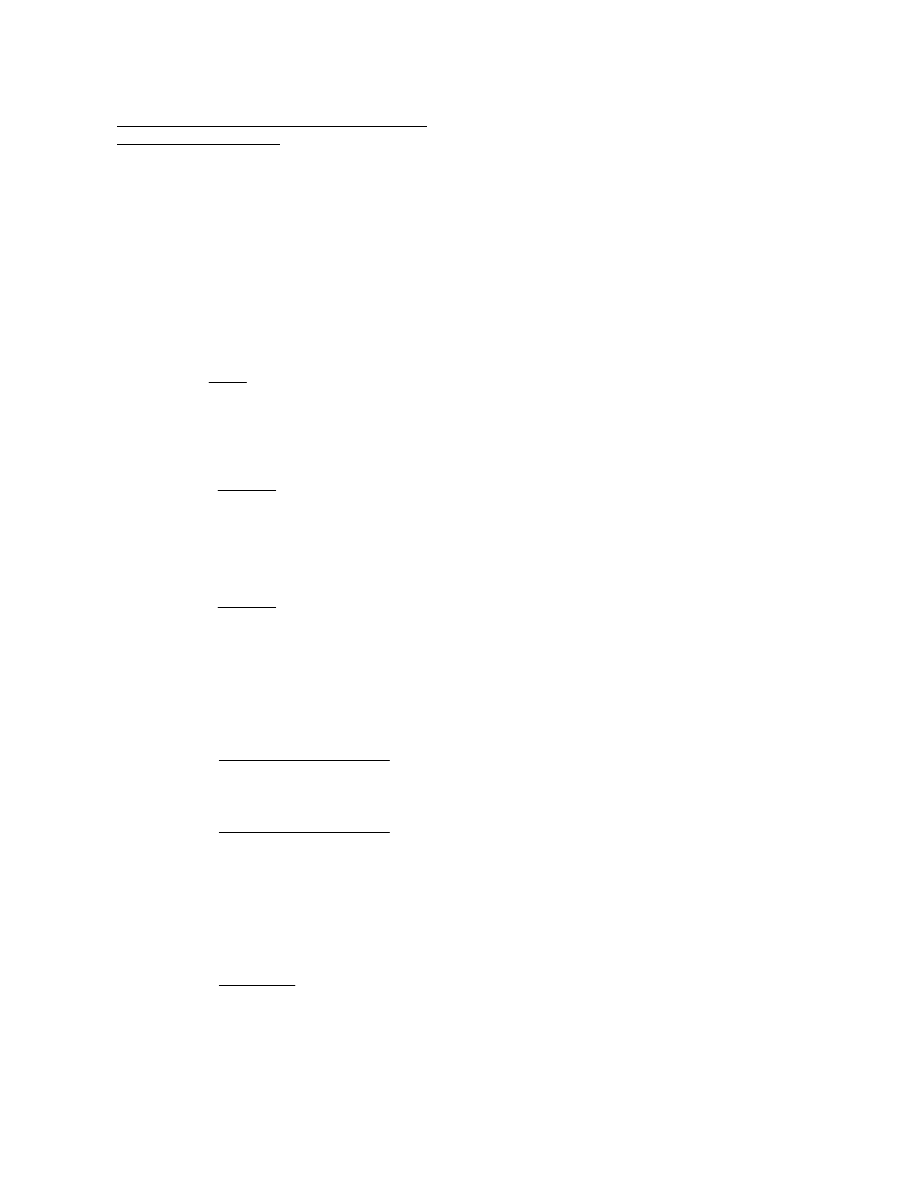
26.5
15.0
−
26.5
0.43
=
Outer:
According to Article 6.8.1, the application of the 85% maximum effeciency factor for splice plates should
be included when using the net section. Therefore, the fraction of hole area that must be deducted in
determining the net section modulus is:
%
10 0.875
0.125
+
(
) 0.375
(
)
36.75 0.375
(
)
100
27.2
=
Inner:
%
20 0.875
0.125
+
(
) 0.375
(
)
75.5 0.375
(
)
100
26.5
=
Outer:
Since the flange is subjected to a net tension, the holes will be considered in computing a net section
modulus for the splice plates. The holes remove the following percentage of cross-sectional area from
each splice plate:
in
2
< 27.6 in
2
OK
0.8 65
(
)
0.95 50
(
)
20.06
(
)
21.96
=
in
2
2 36.75
10 0.875
0.125
+
(
)
−
[
] 0.375
(
)
20.06
=
Inner: A
n
=
in
2
< 28.3 in
2
OK
0.8 65
(
)
0.95 50
(
)
20.81
(
)
22.78
=
in
2
75.5
20 0.875
0.125
+
(
)
−
[
] 0.375
(
)
20.81
=
Outer: A
n
=
Eq (6.13.6.1.4c-2)
φ
u
F
u
φ
y
F
yt
A
n
A
g
≤
A
e
=
The effective areas of the inner and outer splice plates are computed as:
The minimum flange design force, F
cf
A
e
, was computed earlier to be 1,646 kips (tension) (page D-63).
The factored-up moment for strength due to the St. Venant torsional shear was computed earlier (page
D-65) to be 475.7 k-in. Warping torsion is ignored since it is assumed in this example that the spacing of
the internal bracing is sufficient to limit the warping stress to 10 percent of the vertical bending stress at
the strength limit state (Article 6.7.5.3). Further, the specifications do not require warping to be
considered in the design of bolted box flange splices at the strength limit state.
Bolted Splice Design Section 2-2 G2 Node 20.3
Splice Plates (continued)
D-78
Separate calculations similar to those illustrated previously (page D-77 ) show that bearing of the bolts on
the bottom flange is not critical.
If the combined area of the equivalent inner splice plates had not been within 10 percent of the area of the
outside splice plate, the minimum design force and factored-up moment would be proportioned to the inner
and outer plates accordingly.
f = 40.9 ksi < F
n
= 50 ksi OK
ksi
1646
20.81
20.06
+
(
)
475.7
765
+
40.9
=
f =
The combined stress in the bottom flange splice plates is equal to:
in
3
1
12
0.375
(
) 75.5
(
)
3
1587
−
75.5
2
2
1
12
0.375
(
) 36.75
(
)
3
195.8
−
20.06 18.875
(
)
2
+
75.5
2
+
765
=
S
net
=
The net section modulus of the inner and outer splice plates together is therefore equal to:
in
4
2 0.45
(
) 0.875
0.125
+
(
) 0.375
(
) 1.875
2
5.625
2
+
9.375
2
+
13.125
2
+
16.875
2
+
(
)
195.8
=
ΣAd
2
=
27.2
15.0
−
27.2
0.45
=
Inner:
in
4
0.323 2.5
2
6.25
2
+
10
2
+
13.75
2
+
17.5
2
+
21.25
2
+
25
2
+
28.75
2
+
32.5
2
+
36.25
2
+
(
)
1587
=
ΣAd
2
=
in
2
2 0.43
(
) 0.875
0.125
+
(
) 0.375
(
)
0.323
=
A =
Calculate
ΣAd
2
.
Bolted Splice Design Section 2-2 G2 Node 20.3
Splice Plates (continued)
D-79

(This page is intentionally left blank.)
D-80
D-81
Figure D-1. Overhang Bracket Loading
8"
Figure D-2. Internal Diaphragm and Bearing Stiffeners at Pier of Girder 2 Looking Upstation
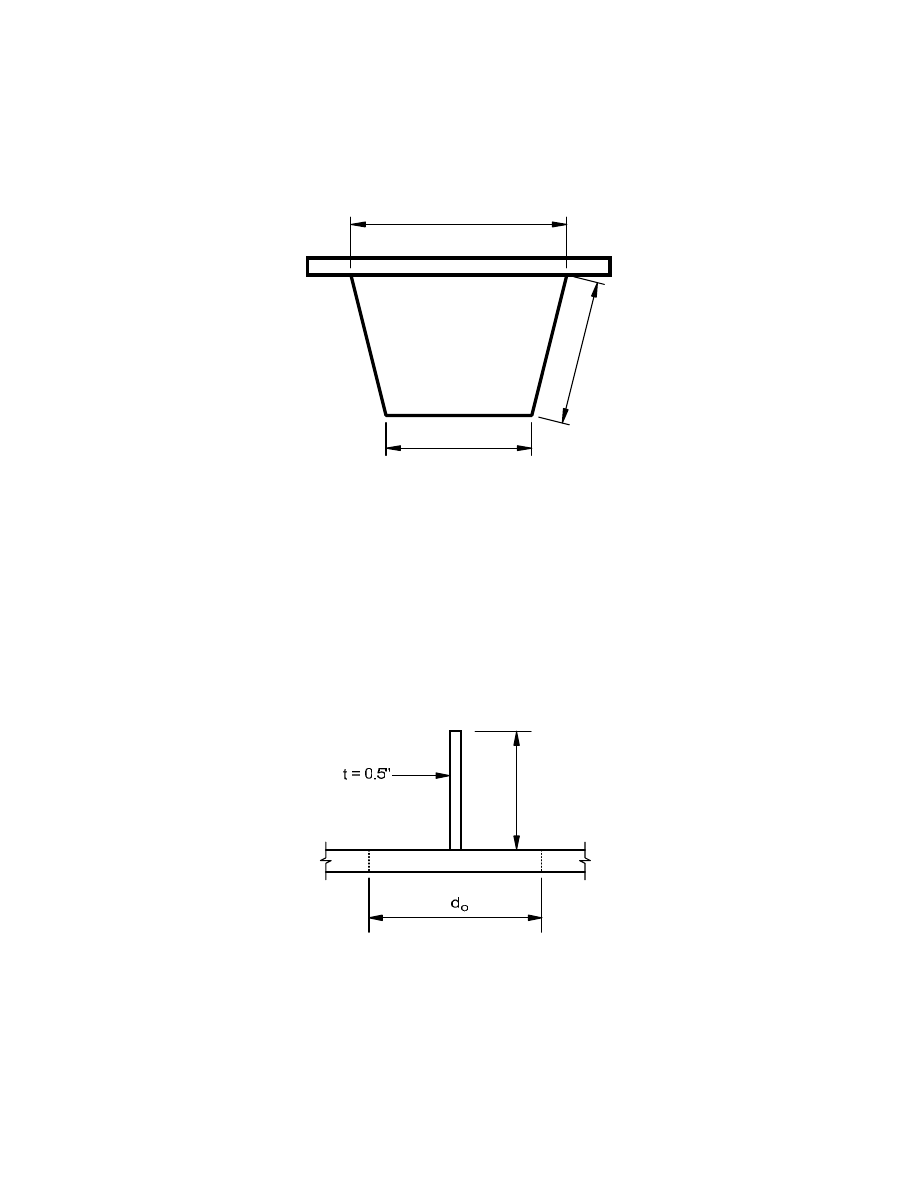
D-82
a = 120"
c
=
8
0.
4"
b = 81"
Figure D-3. Composite Box Cross Section, Girder 2
5.5"
Figure D-4. Effective Width of Web Plate, d
o
, Acting with Transverse Stiffener
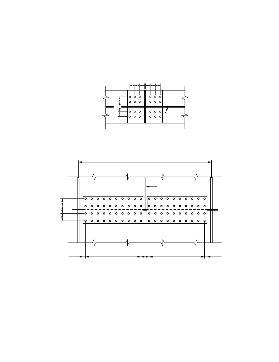
D-83
4 ½”
4 ½”
4 ½”
Flange Width = 81" between centers of webs
Longitudinal
Stiffener
9 Spaces @ 3 ¾”
5"
9 Spaces @ 3 ¾”
1 ½”
1 ½”
6"
3"
3"
Web
3" 3" 3"
3"
3" 3"
Figure D-5. Bolt Patterns for Top and Bottom Flange
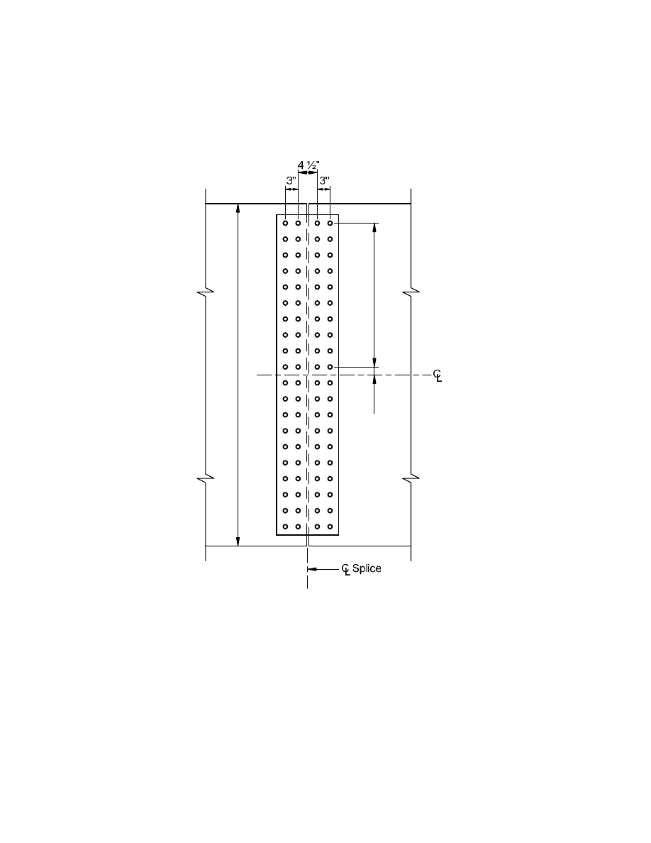
D-84
80.4"
9 Sp
aces @ 3 ¾”
1.
87
5"
Notes: (1) 1/2” gap assumed between the edges of the field pieces.
(2) The indicated distances are along the web slope.
Figure D-6. Bolt Pattern for Web
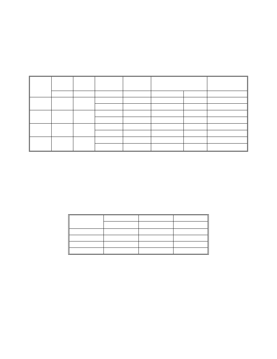
D-85
Table D-1. Strength Limit State at 100 feet from Left Abutment
Factored Loads Shown
Location
Steel
Deck
SupImp
FWS
LRFD (LL + IM)
Strength I
Loading
ksi
ksi
ksi
ksi
ksi
ksi
-0.33 -0.53
Positive
-2.48
-11.67
Top
Flange
-1.6 -6.73
-1.13 -1.78
Negative
14.98
3.74
-0.32 -0.51
Positive
-2.25
-11.21
Top
Web
-1.56 -6.57
-1.10 -1.74
Negative
14.63
3.66
0.79 1.20
Positive
15.87
25.03
Bottom
Flange
1.38 5.79
0.97 1.53
Negative
-12.89
-3.22
0.75 1.19
Positive
15.72
24.70
Bottom
Web
1.35 5.69
0.96 1.51
Negative
-12.67
-3.16
Table D-2. Constructability Limit State at 100 feet from Left Abutment
Service Loads Shown
Steel
Cast #1
1.25 x Sum
Location
ksi ksi ksi
Top Flange
-1.28 -7.62
-11.13
Top Web
-1.25 -7.45
-10.87
Bottom Flange
1.10 6.56
9.58
Bottom Web
1.08 6.45
9.42
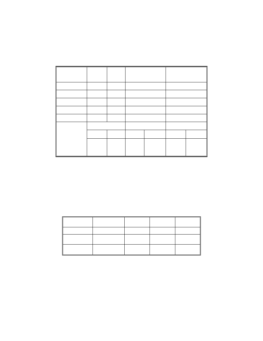
D-86
Table D-3. Unfactored Actions
Load
Moment
(k-ft)
Torque
(k-ft)
Top Flange
Lateral Moment
(k-ft)
Shear
(kips)
Steel 462
-36
-1
-17
Deck 1,941
-125
-7
-69
Cast #1
2,749
-188
-15
-61
SupImp 326 -58
-1
-12
FWS 428
-76
-2
-16
Moment (k-ft)
Torque (k-ft) Shear
(kips)
Pos Neg Pos Neg Pos Neg
Strength HL-
93
with DLA
5,221 -3,080 346 -517
36
-85
Note: Reported shears are vertical shears and are for bending plus torsion in the critical web.
Table D-4. Tub Cross Section
Component
Size (in.)
Area (in
2
) Yield
(F
y
)
Tensile
(F
u
)
Top Flanges
2 - 16 x 1
32.00
50
65
Web
2 - 78 x
0.5625 90.56 50 65
Bottom
Flange
83 x 0.625
51.88
50
65
Note: Other section properties for the gross section may be found in Table C5. The cross
section is the same on both sides of the splice except for the presence of a bottom flange
longitudinal stiffener on one side.

E-1
APPENDIX E
Tabulation of Various Stress Checks

E-2
(This page is intentionally left blank.)

E-3
INTRODUCTION
The following tables show various comparative stress checks between the 2003
AASHTO Guide Specifications and the 2004 AASHTO-LRFD including the 2005 Interim
Specifications.
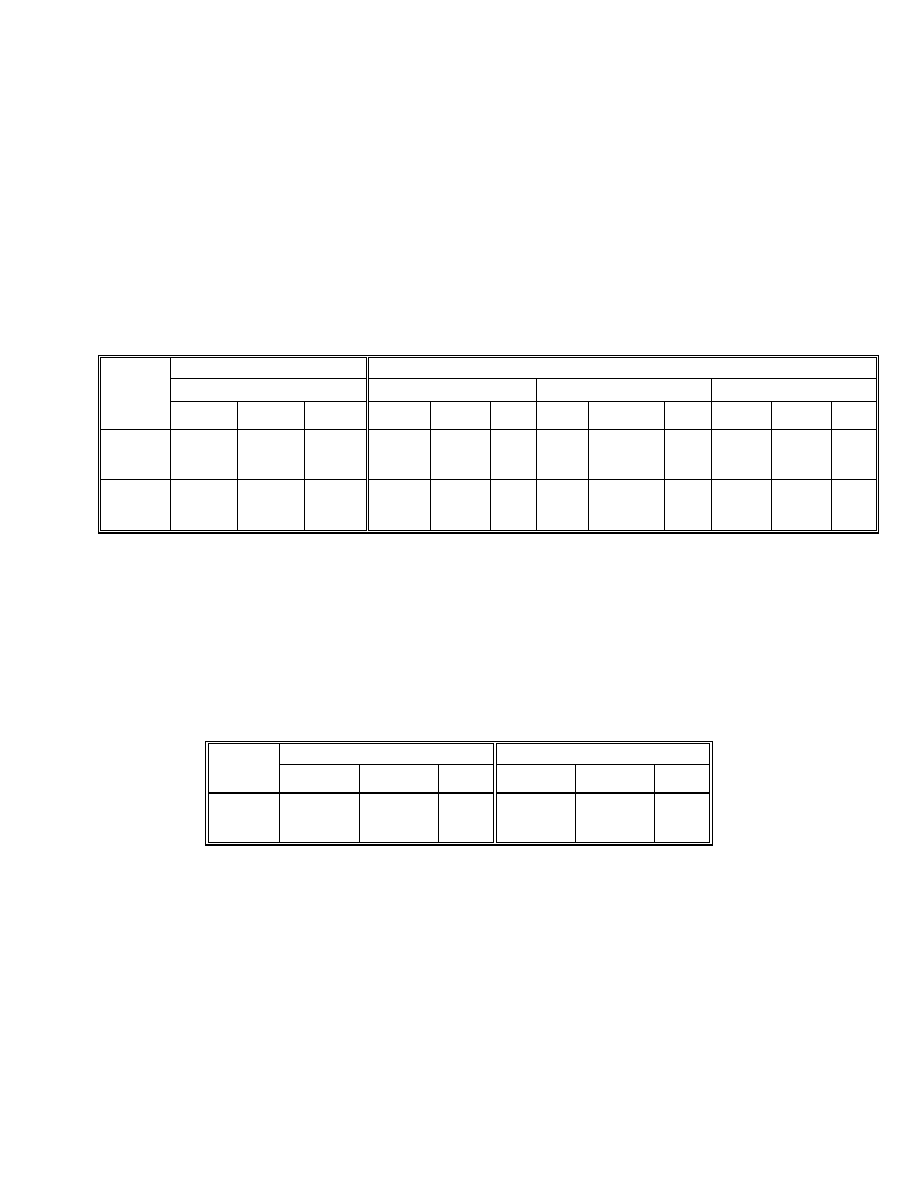
E-4
Table E-1. Constructability – Top Flange
Guide Specifications (LFD)
2004 LRFD Specifications
Eq (6.10.3.2.1-1)
Eq (6.10.3.2.1-2)
Eq (6.10.3.2.1-3)
Section/
Node
F
cr
f
b
ratio
*
φ
f
R
h
F
yc
f
bu
+ f
l
ratio
φ
f
F
nc
f
bu
+ 1/3f
l
ratio
φ
f
F
crw
f
bu
ratio
1-1
9 (G1)
-32.95 -29.32 0.89 -50.0 -30.69 0.61
-44.2 -27.68 0.63 -39.99 -26.18 0.65
1-1
10 (G2)
-36.56 -31.86 0.87 -50.0 -44.54 0.89
-43.7 -33.81 0.77 -39.99 -28.45 0.71
*Applied Stress divided by resistance.
Table E-2. Constructability – Web, Box Girder 2
Guide Specifications (LFD)
2004 LRFD Specifications
Section/
Node
F
cr
f
b
ratio F
crw
f
cw
ratio
1-1
10
-39.89 -31.12 0.78 -39.99 -27.78 0.69
*Applied Stress divided by resistance.
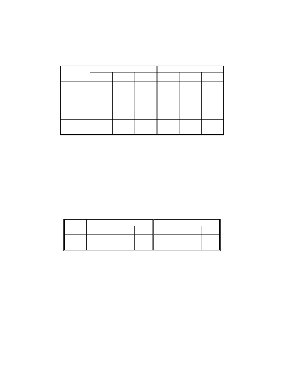
E-5
Table E-3. Strength – Bottom Flange, Box Girder 2
Guide Specifications (LFD)
2004 LRFD Specifications
Section/
Node
F
cr
f
b
ratio
φ
f
F
nc
f
bu
ratio
5-5
36
-47.26 -46.47 0.98 -41.57 -41.6 1.00
At Splice
(Unstiffened
Flange)
2-2
20.3
-6.04 -6.01 0.99 -6.01 -3.22 0.54
*Applied Stress divided by resistance.
Table E-4. Maximum Principal Stresses – Bottom Flange, Box Girder 2
Guide Specifications (LFD)
2004 LRFD Specifications
Section/
Node
F
cr
f
b
ratio F
nc
f
bu
ratio
5-5
36
-49.5 -46.84 0.95 -41.57 -41.6 1.00
*Applied Stress divided by resistance.

E-6
(This page is intentionally left blank.)
Wyszukiwarka
Podobne podstrony:
Precast Prestressed Concrete Horizontally Curved Bridge Beams
05 Yamaoka D i inni Fatigue test of an urban expressway steel girder bridge constructed in 1964
Eurocode 3 Part 1 2 2005 UK NA Design of steel structures General rules Structural fire design
04 Bridge monitoring by horizontal displacement at girder ends
3617449 sap2000 steel bridge model
Eurocode 3 Part 2 2006 UK NA Design of steel structures Steel bridges
11 Nagao Y i inni Steel plate pre stressing reinforcement for coped steel girder ends
Fred Saberhagen Berserker 13 Shiva in Steel
picket window box
H BRIDGE PCB
christmas box
przeglądarka plików Adobe Bridge
Monitor Bridge CAE 3645G
DiagLab UkładKrzepnięcia 2 BOX
horse creep box
Ortopedia Egzamin 2012 BOX
46 643 656 Vacuum HT of Hot Work Steel
więcej podobnych podstron