XXIV
awarie budowlane
XXIV Konferencja Naukowo-Techniczna
Szczecin-Międzyzdroje, 26-29 maja 2009
D
AISUKE
Y
AMAOKA
, yamaoka_dai_ssd@yahoo.co.jp
Kansai University, Osaka, Japan
K
AZUYA
B
ESSHO
, bessho_ssd@yahoo.co.jp
Y
OSHIHIKO
T
AKADA
Hanshin Expressway Management Technology Center, Osaka, Japan
Prof. M
ASAHIRO
S
AKANO
, peg03032@ipcku.kansai-u.ac.jp
Kansai University, Osaka, Japan
FATIGUE TEST OF AN URBAN EXPRESSWAY STEEL GIRDER
BRIDGE CONSTRUCTED IN 1964
BADANIA ZMĘCZENIOWE STALOWEGO MOSTU BELKOWEGO,
NA MIEJSKIEJ AUTOSTRADZIE, WYBUDOWANEGO W 1964 R
Abstract In Japan, infrastructure, including numerous highway and railway bridges, was intensively constructed
during the rapid economic growth era from 1960's to 1970's. We are warned that those structures are now aged
and may deteriorate
in
the
near future.
Since fatigue design had not been applied to highway bridges
until 2002,
there is a high possibility that
fatigue cracking will
occur frequently in the future. In this study, we try to grasp
fatigue behavior and fatigue strength characteristics of the fatigue weak points in the actual bridge through
fatigue tests of steel girders which had been used on an urban expressway for more than 40 years and removed in
2005. As the result,
it was confirmed that the fatigue strength of web gusset welded joint with fillet satisfies JRA
Fatigue Category E which is two-rank higher than that of web gusset joint without fillet.
Streszczenie W Japonii, infrastruktura bogata w mosty kolejowe i autostradowe była intensywnie rozbudowywa-
na podczas gwałtownego wzrostu ekonomicznego przypadającego na lata 1960-1970. Pojawiają się ostrzeżenia,
ż
e te konstrukcje starzeją się
i ich stan może się pogorszyć w najbliższej przyszłości. Ponieważ testy zmęcze-
niowe nie były stosowane do 2002 roku, istnieje duże prawdopodobieństwo, że uszkodzenia zmęczeniowe będą
coraz częstsze w przyszłości. W pracy scharakteryzowano zachowanie i wytrzymałość najsłabszych punktów
w rzeczywistym moście, przez testy zmęczeniowe stalowych belek, które były eksploatowane na miejskiej
autostradzie przez ponad 40 lat i zostały usunięte w 2005 roku.
1. Introduction
In Japan, infrastructure, including numerous highway and railway bridges, was intensively
constructed during the rapid economic growth era from 1960's to 1970's. We are warned that
those structures are now aged and may deteriorate in the near future. Since fatigue design had
not been applied to highway bridges until 2002
[1]
, there is a high possibility that fatigue
cracking will occur frequently in the future.
In this study, we try to grasp fatigue behavior and
fatigue strength characteristics of the fatigue weak points in the actual bridge through fatigue
tests of steel girders which had been used on an urban expressway for more than 40 years and
removed in 2005.
Mosty, drogi i koleje
396
2. Bridge and girders
15830
17128
18425
19718
1
8
9
8
2
1
2
1
2
1
2
1
G- 1
G- 2
G- 3
G- 4
P2
P1
North side
South side
Unit
:
:
:
:
mm
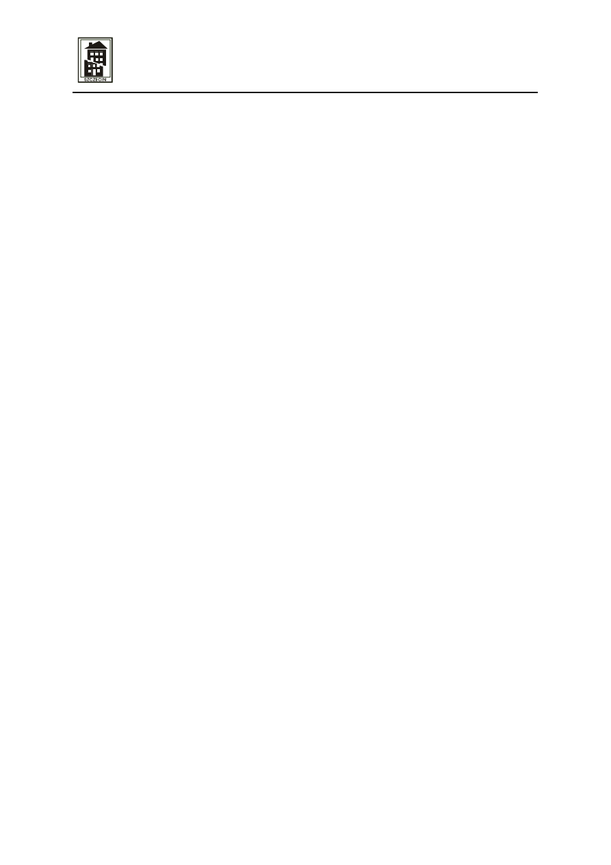
Fig. 1. Plan of Minato-machi Ramp Bridge
16349
15830
Main girder
Slab
Railing
P1
P2
1.001513
1.000000
0.055022
2468
2468
2464
817
994
1
1
8
1
3
0
1
0
7
9211
0.047812
1.000000
1.001142
G- 1
G- 2
G- 3
G- 4
Fig. 2. Elevation of Minato-machi Ramp Bridge
Fig. 3. Cross section of Minato-machi Ramp Bridge
The object of study is the Minato-machi Ramp Bridge, which was real urban expressway
ramp girder bridge constructed in 1964, and removed in 2005. The bridge was a simply-sup-
ported composite main girder bridge. Girders have a web plate and a bottom flange with
welded vertical stiffeners and gusset plates which connect cross frames and lateral bracings to
main girders. Figs.1~3 shows the plan, elevation and cross section of the bridge. Test pieces
were cut out from the red areas shown in Fig. 1.
3. Cracks inspection
3.1. Method
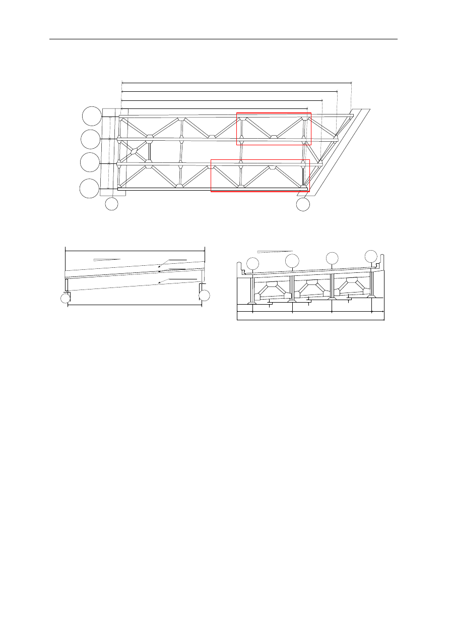
Before the fatigue tests, magnetic particle tests are conducted to detect the fatigue cracks
which could have occurred under service loading. Toes of turn-round weldment are inspected
in the welded joint which connects the gusset plate to the web of the main girder. The total
number of inspected toes of turn-round weldment is 53 in 15 gusset plates. Fig.4 shows
locations of gusset plates and inspected areas.
At first, to confirm the shape and length of paint cracks, the paint cracks are inspected.
Next, the paint is removed by hammer. Finally, we tried to detect the fatigue cracks by
magnetic particle test.
Yamaoka D. i inni: Fatigue test of an urban expressway steel girder bridge constructed in 1964
397
○
:
Inspected
Areas
G- 1
G- 3
G- 4
P1
G- 2
Center side
Edge side
G1- 2
G1- 1
G2- 4
C SC
E
SE
C SC
E
SE
G2- 3W
G2- 3E
C
E
G2- 2
C SC
E
SE
C SC
E
SE
C SC
E
SE
C SC
E
SE
G2- 2E
G2- 2W
C SC
E
SE
C SC
E
SE
G3- 3W
C
E
G3- 3E
G3- 2
C SC
E
SE
C SC
E
SE
C SC
E
SE
G3- 1E
G3- 1W
C SC
E
SE
G4- 1
G4- 2
Fig. 4.
Locations of gusset plates and inspected areas
3.2. Paint cracks inspection
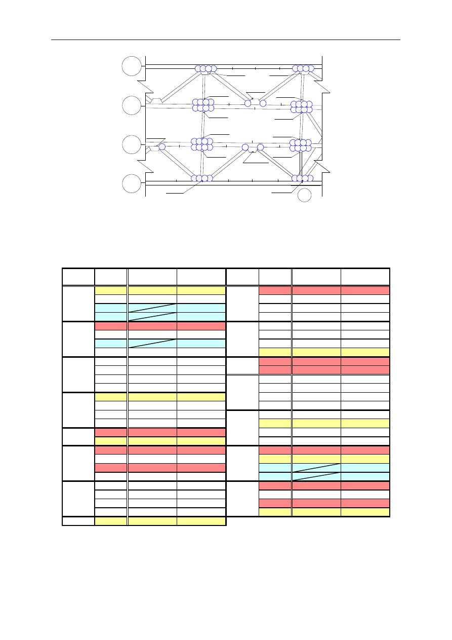
Table 1.
Result of paint cracks inspection
C
12,7,7
C
33
SC
0
SC
0
E
B urne d
E
0
SE
D e te rio ratio n
SE
0
C
83,65
C
0
SC
0
SC
0
E
B urne d
E
0
SE
0
SE
3
C
0
C
13
SC
0
E
27
E
0
C
0
SE
0
SC
0
C
5
E
0
SC
0
SE
0
E
0
C
0
SE
0
SC
17
C
13
E
0
E
12,9
SE
0
C
23
C
23
SC
0
SC
12
E
6
E
D e te rio ratio n
SE
0
SE
B urne d
C
0
C
20,18
SC
0
SC
0
E
0
E
17,9
SE
0
SE
27
G2-4
35,32
G2-3W
G3-1E
G3-1W
G us s e t
P late
Ins pe c te d
A re a
P aint C rac k
L e ngth (mm)
G3-2
G4-2
G2-1W
N o te
G1-1
G2-2
G2-3E
G1-2
G2-1E
G3-3E
G4-1
G3-3W
G us s e t
P late
Ins pe c te d
A re a
P aint C rac k
L e ngth (mm)
N o te
Table 1 shows the result of the paint cracks inspection. Red and yellow areas show paint
crack occurrence areas. There were 18 paint crack occurrence areas in the 53 inspected areas.
Paint cracks in the red areas are along the toes of turn-round weldment which are fatigue
weak points. Paint cracks in the yellow areas are not along the toes of turn-round weldment.
Mosty, drogi i koleje
398
In the 5 blue areas we could not judge the shape and length of the paint crack because of
burning and deterioration.
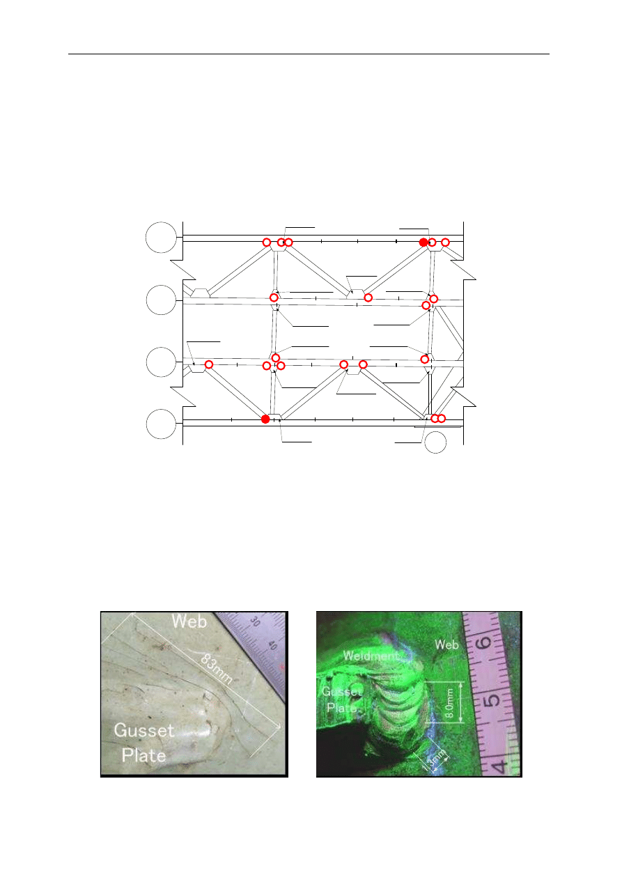
3.3. Magnetic particle test
Fig. 5 shows the result of magnetic particle tests. MT signs that may indicate fatigue cracks
were observed at 2 weldments among the 18 turn-round weldments with paint cracks. Several
paint cracks were observed at the G1-2-C gusset plate.
G2- 2
G2- 3W
G3- 3E
G3- 1E
G2- 1E
G2- 4E
G1- 2
G1- 1
G4- 1
G4- 2
G- 1
G- 3
G- 4
G3- 3W
G3- 1W
G2- 1W
P1
G3- 2
G- 2
G2- 3E
○
:
With Paint crack
●
:
With MT sign
Fig. 5. Results of magnetic particle test
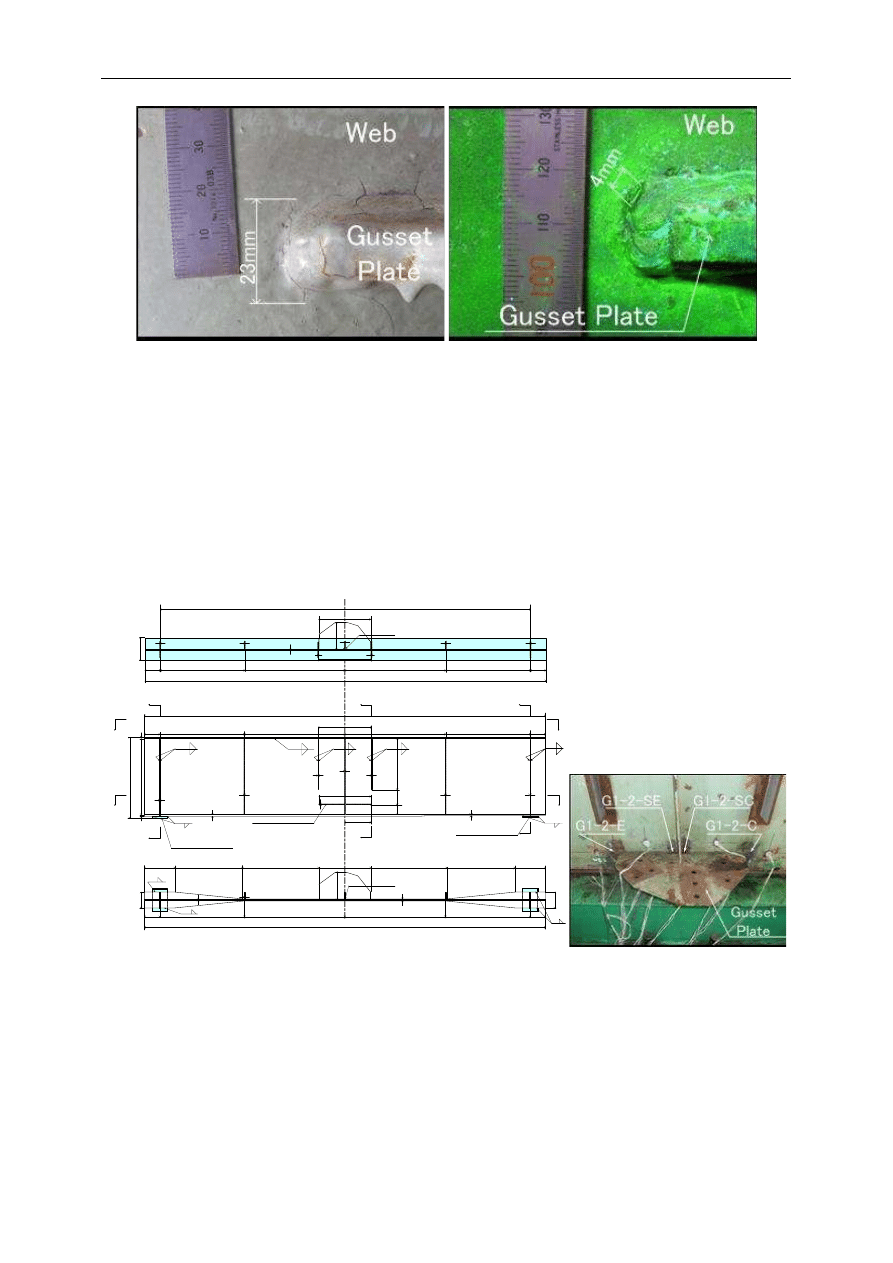
A MT signs of 8 mm and 1.3 mm length were observed under a 83 mm paint crack at the
G1-2-C gusset plate. A MT sign of 4mm length was observed under a 23 mm paint crack at the
G4-1-C gusset plate. Photos 1~4 shows paint cracks and MT signs in the G1-2-C and G4-1-C
gusset plates.
There are no MT signs in the inspected areas that have no paint cracks, or that have paint
cracks in places other than along the toes of turn-round weldment which are fatigue weak
points.
Photo 1. Paint cracks on G1-2-C
Photo 2. MT sign on G1-2-C (N=0cycle)
Yamaoka D. i inni: Fatigue test of an urban expressway steel girder bridge constructed in 1964
399
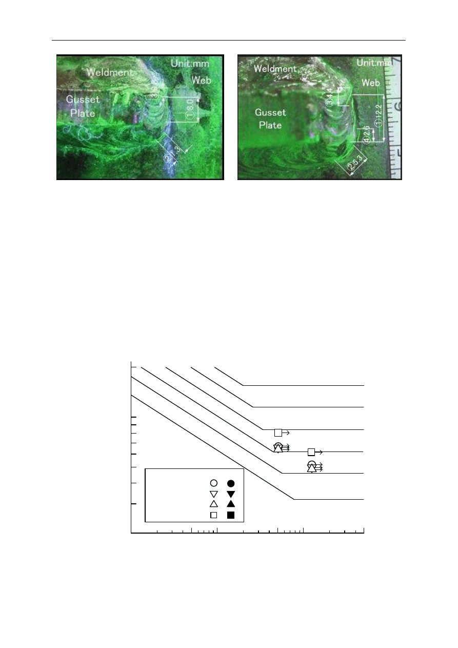
Photo 3. Paint crack on G4-1-C
Photo 4. MT sign on G4-1-C
4. Experimental method
4.1. The configurations and dimensions of specimen
Fig. 6 shows the configurations and dimensions of G1 girder specimen. Due to the capacity
of the testing machine, the depth of girder was reduced by cutting off the upper part of the
girder and welded a new top flange. Photo 5 shows the gusset plate in G1 girder specimen.
The gusset plate has fillets at its both ends.
C
L
5210
680
3
6
0
3
0
0
9
R=30
200
9
150
1319
1319
1111
1111
11
700
9
11
11
11
9
5210
1
08
2
2
2
1
1
7
5
2
9
150
1319
1319
1111
200
a
b
GUSS PL
360× 9× 680
340
1
4
9
680
SOLE PL
300× 15× 200
1
1
3
0
2
0
0
1
3
0
6
6
6
6
6
6
A
A
A
A
C
700
6
1111
A
A
A
A
C
B
B
9
9
11
11
11
11
1
6
5210
680
3
6
0
3
0
R=30
1319
1111
200
9
1000
1319
1111
2
30
150
1000
6
6
6
9
350
890
400
890
2
30
4860
SOLE PL
300× 15× 200
b’
a’
(b) Elevation
(a) a- a’ Plan
(c) b- b’ Plan
Unit:mm
Fig. 6.
Configurations and Dimensions of G1 Girder Specimen
Photo 5. Configuration of Gusset
Plate
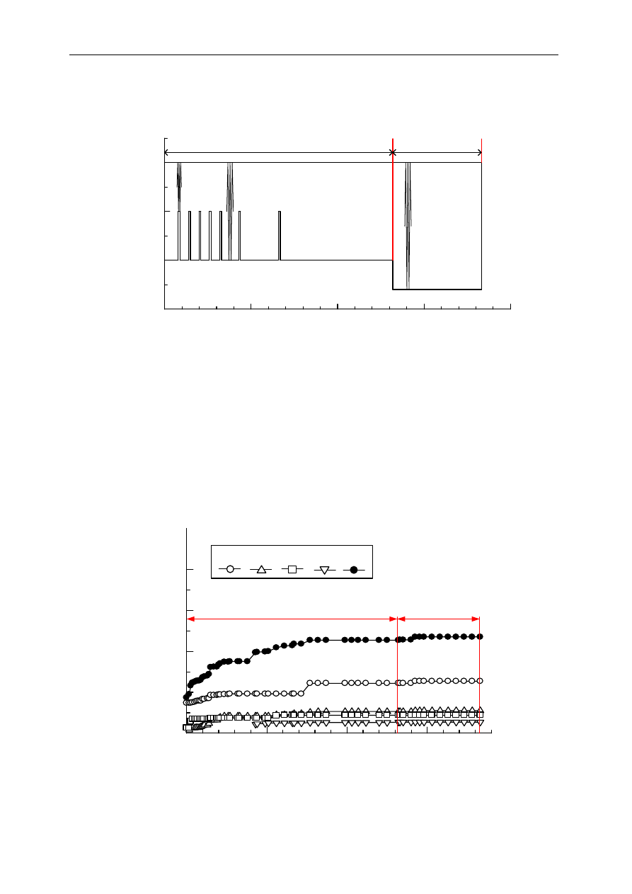
4.2. Fatigue Test Method
Fatigue test was conducted in 4-point bending condition with a loading beam. Loading rate
was 3 Hz. Fig. 7 shows fatigue loading history. After ∆P = 200 kN fatigue loading of
Mosty, drogi i koleje
400
12.5 Mcycles, MT signs at the gusset plate end was propagated so little that. The load range
(∆P) was increased to 260 kN.
5
10
15
20
0
100
200
300
L
oa
d M
a
guni
tude
P
(
kN
)
Total Number of loading cycles Nt (Mcycles)
∆ P=200kN
∆ P=260kN
B.M:100,000cycles
B.M
① ② ③ ④ ⑤
⑥
⑦
18.3
13.2
Fig. 7. Fatigue Loading History
5. Experimental Results
5.1. Fatigue Crack development and Propagation Behavior
Fig. 8 shows the relationship between the length of MT sign and the number of loading
cycles. Photo 6, 7 show MT signs at the G1-2-C gusset plate. A MT sign of 0.8 mm length
was detected after ∆P=200 kN loading of 0.16 Mcycles at the upper part of G1-2-C weldment.
The remarkable propagation of MT signs could not be observed after ∆P = 200 kN loading of
12.5 Mcycles and ∆P = 260 kN loading of 5.1 Mcycles.
5
10
15
0
10
20
30
40
L
e
n
g
th
o
f
M
T
S
ig
n
s
2
a(
m
m
)
Number of loading cycles N (Mcycles)
⊿P=200kN
⊿P=260kN
Sign.2 Sign.3
Sign.1
Sign.4 ∑ 2a
Fig. 8.
Relationship between Length of MT Sign and Number of Loading Cycles
Yamaoka D. i inni: Fatigue test of an urban expressway steel girder bridge constructed in 1964
401
Photo 6 MT sign at G1-2-C (P=200kN,N=0.16Mcycles) Photo 7 MT sign at G1-2-C (P=200kN,N=8.1Mcycles)
5.2. Fatigue Strength
Fig. 9 shows fatigue test results and fatigue design curves after JRA (Japan Road
Association) Fatigue Design Recommendations for Highway Bridges (2002)
[1]
. The vertical
axis represents the maximum principal stress range (∆), while the horizontal axis represents
the fatigue life Nd and Nf. Nd is fatigue crack detection life as the number of stress cycles
until fatigue cracks are detected. Nf is fatigue life defined as the number of stress cycles until
the fatigue crack propagates until the web depth.
No fatigue crack propagation was observed in the gusset plate welded joint after
12.5Mcycles loading under ∆σ = 51MPa and 5.1Mcycles loading under ∆σ = 62MPa.
The fatigue strength of this type of web gusset welded joint with fillet satisfies JRA Fatigue
Category E which is two-rank higher than that of web gusset welded joint without fillet.
100
10
5
10
6
10
7
G
F
E
D
C
JRA-B
20
30
40
50
M
a
x
im
u
m
P
ri
n
ci
p
al
S
tr
e
ss
R
an
g
e
⊿
σ
(M
P
a)
Fatigue Life Nd,Nf(
cycles)
200
G1-2-C
G1-2-E
G1-2-SC,SE
Nf
Nd
Flange-web
Fig. 9. Fatigue Test Results

Mosty, drogi i koleje
402
6. Conclusions
The principal results obtained through this study are as follows.
1) MT signs that may indicate fatigue cracks were observed at 2 weldments from among 18
turn-round weldments with paint cracks.
2) A MT sign of 8mm length was observed under a 83mm paint crack at the G1-2-C gusset
plate. A MT sign of 4mm length was observed under a 23mm paint crack at the G4-1-C
gusset plate.
3) There are no MT signs in the inspected areas which have no paint cracks, or that have paint
cracks in places other than along the toes of turn-round weldment which are fatigue weak
points.
4) The remarkable propagation of MT signs could not be observed after ∆P = 200kN loading
of 12.5Mcycles and ∆P = 260kN loading of 5.1Mcycles
5) It was confirmed that the fatigue strength of this type of web gusset welded joint with fillet
satisfies JRA Fatigue Category E which is two-rank higher than that of web gusset welded
joint without fillet.
References
1. Japan Road Association, “Fatigue Design Recommendations for Highway Bridges”, 2002
(in Japanese).
2. M. Sakano, M. Hozumi, T. Shimora and I. Mikami, "Long Term Fatigue Strength of a Web
Gusset Joint in Floor-Beam-to-Main-Girder Connection", Steel Construction Engineering,
Vol.5, No.18, pp 31–41, June 1998 (in Japanese).
3. M. Sakano, D. Nimura, K. Matumoto, A. Isoda, N. Kondo, K. Arimochi, and N. Konda,
„Improving Fatigue Strength of Welded Beams by Using Fatigue Crack Arresting Steel”,
Euro Steel 2005, Volume B, pp 1.11-25–1.11-32, 2005.
Wyszukiwarka
Podobne podstrony:
Karen MacInerney Tales of an Urban Werewolf 3 Leader of the Pack
11 Yamaoka D i inni Effect of reinforcing method against fatigue cracking of orthotropic steel deck
Design Fatigue Test and NDE of a Sectional Wind Turbine Rotor Blade
05 DFC 4 1 Sequence and Interation of Key QMS Processes Rev 3 1 03
Pancharatnam A Study on the Computer Aided Acoustic Analysis of an Auditorium (CATT)
Congressional Research Services, 'NATO in Afghanistan, A Test of the Transatlantic Alliance', July 2
Sinners in the Hands of an Angry GodSummary
2D Analysis of an Aluminum Bracket
Autopsy of an Egyptian mummy (Nakht ROM I)
ESL Seminars Preparation Guide For The Test of Spoken Engl
comment on 'Quantum creation of an open universe' by Andrei Linde
Summary of an artice 'What is meant by style and stylistics'
Breakdown of an?ucated person
Evidence of an oscillating peripheral clock in an equine fib
formation of an individual
A systematic review and meta analysis of the effect of an ankle foot orthosis on gait biomechanics a
Ćw 05 Antygeny zgodności tkankowej Test mikrolimfocytotoksyczny
więcej podobnych podstron