
XXIV
awarie budowlane
XXIV Konferencja Naukowo-Techniczna
Szczecin-Międzyzdroje, 26-29 maja 2009
Prof. dr inż. M
ARIA
A
NNA
P
OLAK
, polak@uwaterloo.ca
Department of Civil and Environmental Engineering
University of Waterloo, Canada
PREVENTING PUNCHING SHEAR FAILURES OF REINFORCED
CONCRETE SLABS; RESULTS OF STATIC AND PSEUDO-SEISMIC
TESTS ON SHEAR BOLT RETROFITTED SLABS
ZAPOBIEGANIE PRZEBICIU PŁYT śELBETOWYCH ZA POMOCĄ SKRĘCANIA ŚRUBAMI
Abstract The paper presents research program on retrofitting reinforced concrete slab-column connections to
increase their punching shear strength and ductility. The proposed technique using shear bolt reinforcement
allows increasing strength, ductility and rotational capacity of reinforced concrete slab-column connections
which are essential for ensuring structural integrity and preventing progressive collapse of such systems.
The method allows repair and strengthening of existing, previously built, flat reinforced concrete slabs supported
on columns, which do not have adequate punching shear strength at the column area. Steel shear bolts, which
were developed at the University of Waterloo, are new type of reinforcement for retrofitting of existing,
previously built, flat slabs. The shear bolt consists of a headed steel rod threaded at the other end for anchoring
using a washer and nut system. The bolts are installed in holes drilled in a slab in concentric perimeters around
the column. The results of the experimental work include twenty three large-scale reinforced concrete slab-
column connections tested under static and reversed cycling horizontal loads. The performance of strengthened
slabs is shown in a form of load-displacement curves and hysteretic response, which demonstrate how transverse
reinforcements increase punching shear capacity, ductility and energy dissipation capability of slab-column
connections.
Streszczenie W pracy przedstawiono program badawczy dotyczący modernizacji połączeń płyt żelbetowych
wspartych na słupach, tak by nastąpiła poprawa ich ciągliwości oraz wytrzymałości na przebicie. Zaproponowana
technika – stosująca zbrojenie za pomocą śrub – pozwala na wzrost wytrzymałości, ciągliwości i zdolności do
obrotu wzmocnionych połączeń płyt żelbetowych ze słupami, co jest istotne dla zapewnienia integralności
konstrukcji i zapobiegnięcia katastrofie postępującej takich układów. Metoda pozwala na reperacje i wzmocnie-
nia istniejących, dawniej zbudowanych zbrojonych płyt betonowych wspartych na słupach, które nie mają
odpowiedniej wytrzymałości na ścinanie w pobliżu słupów. Stalowe śruby, opracowane na Uniwersytecie
Waterloo, stanowią nowy rodzaj zbrojenia dla modernizacji istniejących płaskich płyt. Śruba składa się ze
stalowego pręta zakończonego łbem, gwintowanego z drugiego końca tak by dało się go zamocować stosując
układ: podkładka + nakrętka. Śruby instaluje się w otworach wierconych w płytach, koncentrycznie wokół
słupów. Testy eksperymentalne przeprowadzono na dwudziestu trzech połączeniach płyt żelbetowych ze słupami
– w dużej skali – poddanych obciążeniu statycznemu i zmieniającemu się cyklicznie obciążeniu horyzontalnemu.
Zachowanie się wzmocnionych płyt przedstawiono w formie krzywych obciążenie – przemieszczenie i histere-
tycznych odpowiedzi układu, pokazujących jak zbrojenie poprzeczne zwiększa wytrzymałość na przebicie,
ciągliwość i zdolność rozpraszania energii zmodernizowanych połączeń płyta-słup.

Konstrukcje żelbetowe
794
1. Introduction
Flat reinforced concrete slab-column structural systems are easy to construct. However,
some of the moist catastrophic failures occurred in such structures. The slab area around the
column is subject to bending and shear actions, which cause complex three-dimensional stress
and strain states and result in principal tension stresses being inclined with respect to
the slab’s plane. Therefore, flexural reinforcement alone cannot provide adequate ductility of
these connections. Adding shear reinforcement at the column area of these slabs can
substantially increase punching shear capacity and ductility, however, in many practical cases,
especially in buildings designed using older codes, these shear reinforcements were not
provided during construction.
Structural ductility is necessary for robustness and for avoiding progressive collapse in
case of the connection’s failure. Designs, according to every design code, ensure that the con-
nection should fail in flexure before reaching its punching shear strength. This is done because
flexural failures of properly designed reinforced concrete members and member connections
are ductile, ensuring substantial load carrying capability and rotational capacity after yielding
of the flexural reinforcement. However, flexural failures can trigger post peak punching shear
failures due to extensive cracking of the concrete and corresponding reduced shear strength.
Therefore, ensuring structural integrity such as to prevent progressive collapse of such
structures requires that this punching failure be also ductile. This can be done if a proper shear
reinforcement is placed in the slab and an adequate longitudinal integrity reinforcement is
placed in the slab’s compression zones.
This paper describes tests related to a retrofit method for preventing structural collapses of
the reinforced concrete flat slab-column type structural systems. It concentrates on a retrofit
system for existing slabs which were not reinforced for punching shear during construction.
This system, shear bolts, allows strengthening slabs without extensive cost and without
changing their appearance [1], [2], [3].
2. Structural collapses due to punching shear
Several cases of punching shear failures were reported in the last few decades. These
occurred either during construction when shoring was removed before proper concrete
strength developed, due to openings in slabs near columns, or due to construction or design
errors [4].
In 1962, in New York City, a part of a roof of a car garage, collapsed suddenly [4].
The roof was supporting 1.2 m deep earth cover with vegetation on it. It was found that
the slab punched through a column and there was little damage in other places of the slab.
The reason was that the earth on the slab was saturated and frozen, which increased the load.
It was also found that, the slab was constructed with insufficient punching shear capacity.
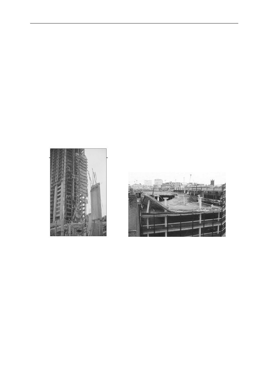
In 1973, the high-rise apartment building, Skyline Plaza, suffered a progressive collapse
during construction. The collapse started at the 23
rd
floor by punching shear and progressed to
the basement (Fig. 1). Fourteen workers were killed. [5].
On March 20
th
1997 collapsed a part of the roof of the Pipers Row Multi-Storey Car Park
that was built in 1965 [6]. The failure was due to a punching shear which developed into
a progressive collapse. Pipers Row Multi-Storey Car Park was built using the Lift Slab system
of construction, in which concrete floor slabs, cast at ground level, are lifted up precast
columns and then supported on wedges engaging in welded angle shear collars cast into the
slab. The punching shear failure occurred outside the shear head leaving the Lift Slab shear
head and column connections intact. Poor concrete quality in the slabs was deemed
Polak M. A.: Preventing punching shear failures of reinforced concrete slabs; results of static…
795
responsible for the failure. However, this example clearly shows that column capitals cannot
prevent brittleness of failure if such is to take place
.
During an earthquake, the horizontal movement of the ground induces large horizontal
inertia forces and lateral drifts in the buildings. The inter-story drift makes the flat slab-
column connection rotate and produce moments in the connection. The moments increase
punching shear stress in a concrete slab around the column area. Therefore, the flat slab
structures are easy to be damaged in earthquakes. In 1985 Mexico City earthquake, 91 waffle
slab structures collapsed and 44 were severely damaged [7]. This was the most vulnerable
type of structure in that earthquake. Waffle-type slabs have solid slab sections at the column
connections, thus they show similar behaviour to flat slab structures when punching is
considered. Some of them were damaged by punching shear failure of the slabs. Others were
damaged by column failures.
In the 1994 Northridge earthquake, a four-story reinforced concrete slab-column building
was severely damaged. The outside perimeter consisted of ductile moment frames. Slabs (with
drop panels) were post tensioned. Each of the first floor and the second floor was damaged in
six slab-column connections. Also, there was cracking and spalling of concrete on the peri-
meter frame [8].
a)
b)
Fig. 1. Collapse of a) Skyline Plaza [11], b) Pipers Row park garage [10]
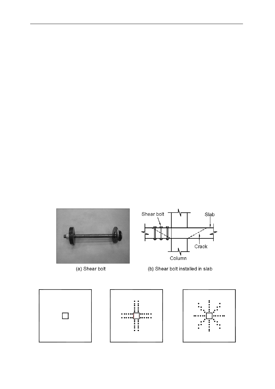
3. Shear bolts
Shear bolts, developed at the University of Waterloo, consist of a stem with a head on one
end and a washer with nut at the other threaded end. The method is conceptually simple and
aesthetically appealing. The retrofit involves drilling small holes in a slab, around the column
area, inserting bolts into them and tightening the nut at the threaded end (Figure 2).
4. Experimental program
The presented experiments were all done at the University of Waterloo on isolated slab-
column interior and edge connections under static and pseudo-dynamic loadings. The expe-
rimental program was designed to study the behaviour of slabs retrofitted with shear bolts.
All specimens were full-scale and represented portions of a slab-column continuous system,
bounded by the lines of contraflexure around the column. The dimensions of the specimens
Konstrukcje żelbetowe
796
(1800
×
1800
×
120 mm for interior columns with supports at 1500
×
1500 perimeter; and
1540×1020×120 mm for edge columns with supports at 1500
×
1000 perimeter) are equivalent
to a portion of a typical floor system consisting of three 3.75 m bays in one direction and any
number of 3.75 m bays in the other direction. Reinforcement was provided in tension (1.2%
for interior, 0.75% for edge connections) and compression layers (0.55% for interior, 0.45%
for edge connections) with 20 mm concrete cover to the outer bars. Some tested slabs had
openings next to columns. The columns’ cross sections were: 150
×
150 for interior static,
250
×
250 for edge static, and 200
×
200 for interior pseudo-seismic tests. Two edge slabs were
strengthened with FRP laminates and shear bolts. The specimens were simply supported along
the edges with corners restrained from lifting (static loading), or with the edge normal to
horizontal load restrained from lifting (pseudo-dynamic tests). To allow for some rotation
at the supports, the slabs were placed on neoprene pads attached to W-shape steel beams.
The pseudo-dynamic test specimens were subjected to a vertical constant load (Table 1),
simulating gravity loads and cyclic reversed lateral displacements simulating seismic event.
The top and bottom column stubs extending 700mm from the center of the slab were used
for application of the horizontal displacements. The static tests, edge and interior connections,
include 14 specimens (including control specimens), while pseudo-dynamic tests were done
on 9 specimens. The interior connections were strengthened with 9.5 mm diameter shear bolts
placed in different number of peripheral rows around the column. The edge connections were
strengthened using 12.7 mm diameter bolts. The bolts were placed either in orthogonal or
radial patterns; an example is shown in Figure 3 which shows specimens with 6 peripheral
rows of shear bolts. The top of the slab in the testing configuration was a compression face
(under gravity loads), thus the slabs were tested in an upside down position as compared to the
actual situation in buildings. The details of all presented specimens can be found in Table 1
and in [1], [2], [3].
Fig. 2. Shear bolt and its installation in concrete slab
Orthogonal pattern
control
Radial pattern
Fig. 3. Examples of shear bolt patterns used in the experiments

Polak M. A.: Preventing punching shear failures of reinforced concrete slabs; results of static…
797
5. Slab-Column Interior Connections
Specimen SB1 had no shear bolts while SB2, SB3 and SB4 had two, three and four
peripheral rows of 9.5 mm diameter shear bolts (8 bolts in each row), respectively. Specimens
SB5 and SB6 both contained four rows of shear bolts and also had openings (70
×
70 mm)
placed next to the columns. The slabs were tested in a displacement control mode.
Figure 4 shows the central deflection for all specimens recorded by the internal LVDT of the
top loading actuator. The observed displacements showed improved ductility with the increase
in the number of shear bolts. Specimen SB2 reached its flexural capacity and failed immediately
after by punching outside the shear reinforced zone. Specimens SB3 and SB4 yielded at peak
load (flexural failure) and then sustained large post-peak deflection at constant load, until final
punching failure of the slab occurred outside the shear reinforced zone. Ductility, calculated as
the ratio of the deflection at the first yield of flexural reinforcement to the ultimate deflection,
was found to increase with the number of shear bolts (Table 1). Slabs with openings (SB5 and
SB6) also reached their flexural capacities, and then allowed for some post-peak deflections
until punching occurred through the shear studs. At this point the slabs did not break but
continued to allow deflections with the reduced load capacity of the connection. These results
show that failures occurring in the shear-reinforced zone are ductile.
6. Slab-Column Edge Connections
Tests on slab-columns edge connection with shear bolts (6 specimens) are compared to
specimens without shear reinforcements, XXX, SF0 and their identical counterparts, XXX-R
and SF0-R with 9.5 mm diameter shear studs (six peripheral rows placed during construction)
[5], [6]. Details regarding the specimens are given in Table 1 and in [1]. SF0, SF0-R and SH-
2SR had an opening (150
×
150 mm) immediately in front of the column. The shear bolts were
manufactured from 12.7 mm diameter rods.
All specimens were subjected to a constant M/V ratio of 0.3. The results are presented in
Figure 5. Table 1 shows that shear reinforcement in slabs increases strength and ductility of
the connections. Shear studs prevented punching shear failures in both XXX-R and SF0-R.
Shear bolts, applied to the existing hardened slabs, also prevented punching shear failures of
the specimens by increasing their strength and ductility. The slabs reinforced with shear bolts
had almost the same behaviour and strength as the slabs with shear studs. The shear-bolt
reinforced slabs underwent larger post-peak deflections and rotations; however, since this
testing was done in load control, it is difficult to quantify the post-peak ductilities. It can be
however, observed that for both types of reinforcements the ductility of the connection is
substantially increased in comparison with unreinforced specimens. The final crack pattern for
the specimens SB1 and SB4 are shown in Fig 7
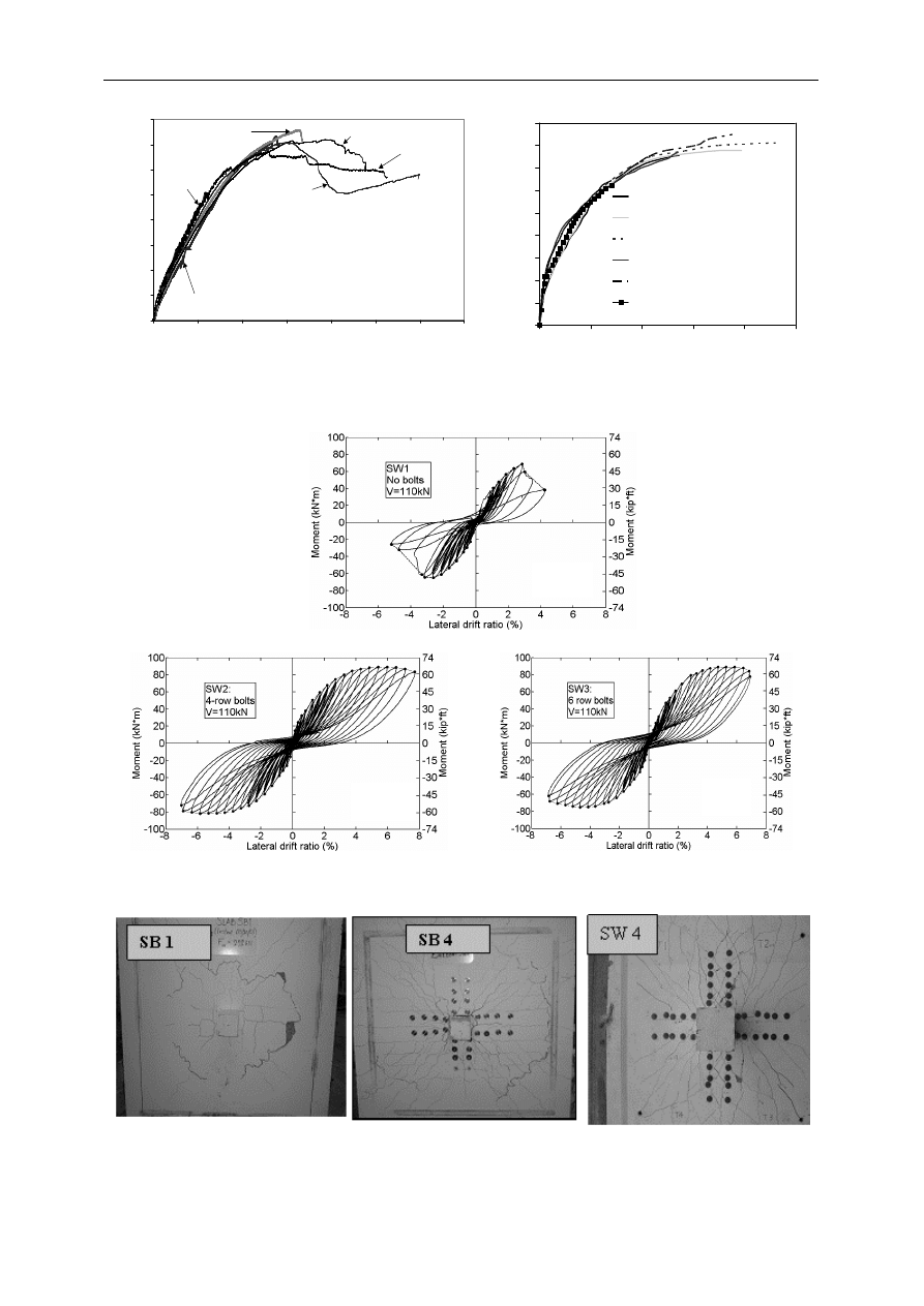
7. Interior connections under pseudo-seismic loads
1) Nine specimens were tested in this series (SW1 ~ SW9). Top horizontal lateral load versus top
horizontal lateral drift ratio for SW1, SW2 and SW3 are shown in Figure 6. Significant
differences exist between the responses of the specimens with and without shear bolts. The spe-
cimen without shear bolts, SW1, reaches the maximum moment of 69 kNm. The maximum
moment was achieved at 2.85% drift after which the specimen failed by punching. Specimen
SW2, which contained 4 rows of shear bolts, reached the maximum moment of 89 kNm at 6%

Konstrukcje żelbetowe
798
drift. SW3 (6 rows of shear bolts) reached also 89 kNm at 5.3% drift. After reaching the maxi-
mum load the specimen continued to deform with minimal loss of load bearing capability.
Table 1. Summary of experimental program on shear bolts at the University of Waterloo
Type
Name
Comments
Test Failure
Load Vertical
[kN]
/moment
[kNm]
Ductility
(mm/mm)
XXX
Control, n.o.
125/38
4
SF0
Control, openings
110/33
3
SX-
1SR
shear bolts, n.o., 1 row, s.p.
151/45
5.9
SX-
2SR
shear bolts, n.o., 2 rows, s.p.
155/47
12.4
SX-
2SB
shear bolts, n.o., 2 rows, s.p.
162/49
8.7
SH-
2SR
shear bolts, 1 opening, 2 rows, s.p.
141/42
6.1
SX-
GF-SB
shear bolts and FRP laminates on tension side,
n.o., 2 rows, s.p.
170/51
8.2
E
d
g
e,
s
ta
ti
c
SH-
GF-SB
shear bolts and FRP laminates on tension side,
1 opening, 2 rows, s.p.
162/49
6.4
SB1
Control, n.o.
253/0
1.0
SB2
shear bolts, n.o., 2 rows, o.p.
364 /0
2.0
SB3
shear bolts, n.o., 3 rows, o.p.
372/0
2.1
SB4
shear bolts, n.o., 4 rows, o.p.
360/0
3.4
SB5
shear bolts, 4 openings, 4 rows, o.p.
353/0
5.0
In
te
ri
o
r,
s
ta
ti
c
SB6
shear bolts, 2 openings, 4 rows, o.p.
336/0
4.1
SW1
Control, n.o. P=110kN
110/69
2.1
SW2
shear bolts, n.o., 4 rows, o.p. P=110kN
110/89
6.5
SW3
shear bolts, n.o., 6 rows, r.p. P=110kN
110/89
6.6
SW4
shear bolts, n.o., 6 rows, o.p. P=160kN
160/93
5.4
SW5
shear bolts, n.o., 6 rows, o.p. P=160kN
160/78
2.6
SW6
Control, 2 openings, P=160kN
160/53
-
SW7
shear bolts, 2 openings, 6 rows, o.p. P=160kN
160/57
1.3
SW8
shear bolts, 2 openings, 6 rows, r.p. P=160kN
160/64
1.0
In
te
ri
o
r,
p
se
u
d
o
-d
y
n
am
ic
SW9
shear bolts, n.o. 6 rows, r.p. P=160kN
160/94
4.1
n.o. = no openings; r.p. = radial pattern; o. p. =orthogonal pattern, P = constant vertical
load for pseudo seismic tests.
Polak M. A.: Preventing punching shear failures of reinforced concrete slabs; results of static…
799
Load vs Internal LVDT
0
50
100
150
200
250
300
350
400
0
10
20
30
40
50
60
70
Deflection (mm)
A
p
p
li
e
d
L
o
a
d
(
k
N
)
SB2
SB1
SB3
SB4
SB5
SB6
0
20
40
60
80
100
120
140
160
180
0
10
20
30
40
50
Deflection (mm)
V
e
rt
ic
a
l
L
o
a
d
(
k
N
)
SX-1SR; shear bolts, one row
SX-2SR; shear bolts, two rows
SX-2SB; shear bolts, two rows
XXX-R; shear studs
SX-GF-SB; GFRP strips, shear
bolts, three rows
XXX; control
Fig. 4. Load versus central displacement for internal
connection
Fig. 5. Comparison of the vertical dimension of
shear cracks for SB1, Sb2, SB3 and SB4
(a)
(b)
(c)
Fig. 6. Horizontal load vs. horizontal drift ratio at top column end.
Fig. 7. Final crack patterns on tension side for SB1, SB4 with no openings and four rows of shear bolts and SB 6
with two openings and four rows of shear bolts

Konstrukcje żelbetowe
800
Peak drift ductility, defined as a ratio between lateral displacement at peak load and displa-
cement at the first yield of longitudinal reinforcement, is shown in Table 1. All specimens
with shear reinforcement experienced peak ductilities much larger than their counterparts
without shear reinforcement. The final crack pattern for the specimen SW4 is shown in Fig 7.
8. Conclusions
The presented research shows that shear bolts can be effective as a method for punching
shear retrofit of flat slabs subjected to static and seismic loads. Shear bolts provide means for
changing the failure mode from punching to flexural. They increase both strength and ductility
of the connection being at the same time simple and cost effective.
The method has a potential for practical field applications for strengthening of reinforced
concrete slabs subjected to gravity, transverse and earthquake loadings. It can also be impor-
tant for abnormal loading scenarios, which can trigger progressive collapse of the surrounding
structure. Shear bolts may well serve to dwarf such devastating failure if appropriately
retrofitted into existing flat slab structures.
References
1. El-Salakawy E., Polak M.A., Soudki K.: New Shear Strengthening Technique for Concrete
Slabs. ACI Structural Journal, 100 (3)/2003, 297–304.
2. Adetifa B. and Polak M.A.:Retrofit of Interior Slab Column Connections for Punching
using Shear Bolts. ACI Structural Journal, 102(2)/2005, 268–274.
3. Bu W. and Polak M.A.: Seismic Testing of Interior Slab-Column Connections
Strengthened with Shear Bolts. ACI Structural Journal, in print, 2009.
4. Feld, J. and Carper, K. L.: Construction Failure. 2
nd
Edition, John Wiley & Sons, Inc./
1997.
5. Carino N. J., Woodward K.A., Leyendecker E.V., Fattal S.G.: A Review of the Skyline
Plaza Collapse. Concrete International, 5(7)/1983, 35–42.
6. Wood J.G.M.: Pipers Row Car Park, Wolverhampton, Quantitative Study of the Causes of
the
Partial
Collapse
on
20th
March
1997
report
http://www.hse.gov.uk/research/misc/pipersrow.htm
7. Rosenblueth E. and Meli R.: The 1985 earthquake: causes and effects in Mexico City.
Concrete International, 1986.
8. Sabol T. A.: Flat Slab Failure in Ductile Concrete Frame Building. 1994 Northridge
Earthquake, Case Study 1.13/1994, 167–187.
9. El-Salakawy E.F., Polak M.A., Soliman, M.H.: Reinforced Concrete Slab-Column Edge
Connections with Shear Studs. Canadian Journal of Civil Engineering, 27/2000, 338–348.
10. El-Salakawy E.F., Polak, M.A., Soliman, M.H.: Reinforced Concrete Slab-Column Edge
Connections with Openings. ACI Structural Journal, 96(1)/1999, 79–87. Wright R.N.:Fire
and Building Research. NIST BSS 179/2003.
Wyszukiwarka
Podobne podstrony:
Correspondence of Roosevelt and Truman with Stalin on Lend Lease and Other Aid to the Soviet Union
Use of clinical and impairment based tests to predict falls by community dwelling older adults
[Engineering] Electrical Power and Energy Systems 1999 21 Dynamics Of Diesel And Wind Turbine Gene
„SAMB” Computer system of static analysis of shear wall structures in tall buildings
Analysis of Reinforced Concrete Structures Using ANSYS Nonlinear Concrete Model
Mechanical failure of external fixator during hip joint distraction for Perthes disease
[Mises org]Grams,Mart Failure of The New Economics Study Guide
Failure of Gun Control Laws
Fundamentals of Anatomy and Physiology 8e M15 MART5891 08 SE C15
Adolf Hitler vs Henry Ford; The Volkswagen, the Role of America as a Model, and the Failure of a Naz
Fundamentals of Anatomy and Physiology 8e A01 MART5891 08 SE ESHT
Fundamentals of Anatomy and Physiology 8e A01 MART 5891 08 SE FM
Fundamentals of Anatomy and Physiology 8e DES MART5891 08 SE DE#2DDEA
Tea polyphenols prevention of cancer and optimizing health
Fundamentals of Anatomy and Physiology 8e Z03 MART 5891 08 SE ANS
Fundamentals of Anatomy and Physiology 8e Z05 MART 5891 08 SE PCRED
Fundamentals of Anatomy and Physiology 8e DES MART5891 08 SE C0#2DDE9
Fundamentals of Anatomy and Physiology 8e Z02 MART 5891 08 SE App
Fundamentals of Anatomy and Physiology 8e Z07 MART 5891 08 SE INDX
więcej podobnych podstron