33-0660 Replacing rubber bellows on front axle shaft
Preceding work:
Operation no. of operation texts and work units or standard
33-0620 Removing and installing front axle shaft
texts and flat rates
P33-5152-55
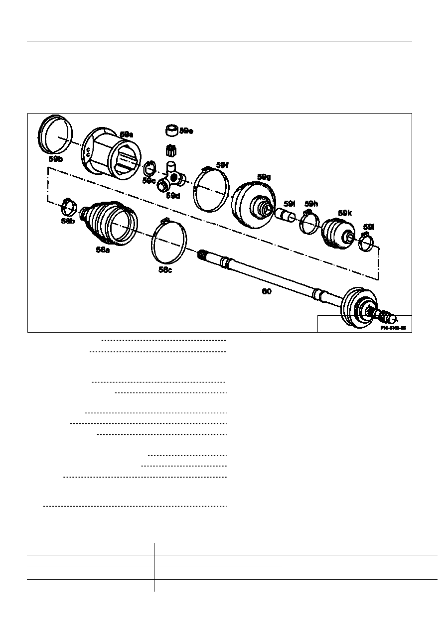
Front axle shaft (60)
clamp, release. Use clamping jaws (No. 1).
Hose clamp (59f)
detach, replace, tighten (No. 2).
Mark position of joint casing (59a) in relation to
tripod spider (59d) mark (No.3).
Joint casing (59e)
remove, install (Nos. 3 and 14).
Tripod joint rollers (59e)
secure to prevent falling out. Each joint roller
supported with 32 needles (No. 5).
End cover (59b)
remove, install (Nos. 4 and 13).
Circlip (59c)
remove, replace and install (Nos. 6 and 11).
Tripod spider (59d)
remove, slide in up to the stop (Nos. 7 and 11).
Hose clamps (58b, 58c, 59h, 59l)
detach if required, replace, and tighten.
Rubber bellows (58a, 59g, 59k)
remove if required, replace, and install.
Bush (59i)
remove, install. Assemble rubber bellows (59g
and 59k) in correct relationship and ensure
correct seating (Nos. 8 and 10).
Test
all parts (No.9).
Lubricant
Rzeppa outer joint
120 g MB Low - viscosity grease Part no. refer to parts microfilm
Tripod inner joint
390 g Tripod joint grease
Strona 1/7
© Daimler AG, 21.07.12, G/03/09 / ra334m1240660x / 0660 - Replacment of the rubber bellows on the front axle shaft Drive 4MATIC
Commercially available tools
Designation
e.g. Company, order no.
Three-arm puller
Kukko,
D-5630 Remscheid, 30-1
Assembly pliers for hose clamp
Hans Oetiker GmbH,
D-7833 Endingen 1, 1098i
Circlip pliers
Hazet
D-5630 Remscheid 1
P33-5153-55
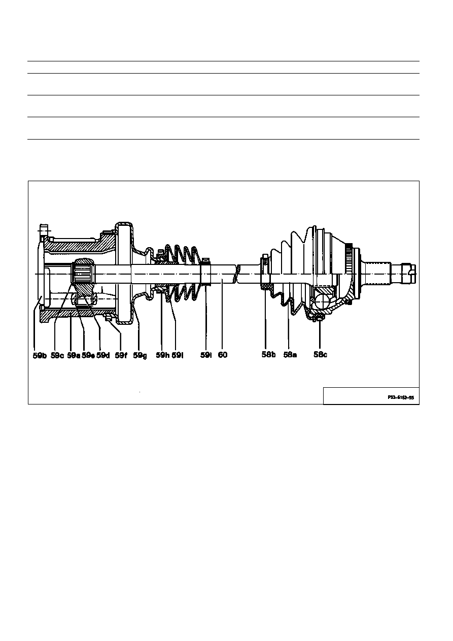
58a
Rubber bellows
59f
Hose clamp
58b
Hose clamp
59g
Rubber bellows
58c
Hose clamp
59h
Hose clamp
59a
Tripod joint casing
59i
Bush
59b
End cover
59k
Rubber bellows
59c
Circlip
59l
Hose clamp
59d
Tripod spider
60
Front axle shaft
59e
Tripod joint rollers
Note
The rubber bellows on the outer joint can only be
replaced after stripping down the inner joint since
it is not possible to strip down the outer joint.
Strona 2/7
© Daimler AG, 21.07.12, G/03/09 / ra334m1240660x / 0660 - Replacment of the rubber bellows on the front axle shaft Drive 4MATIC
Dismantling
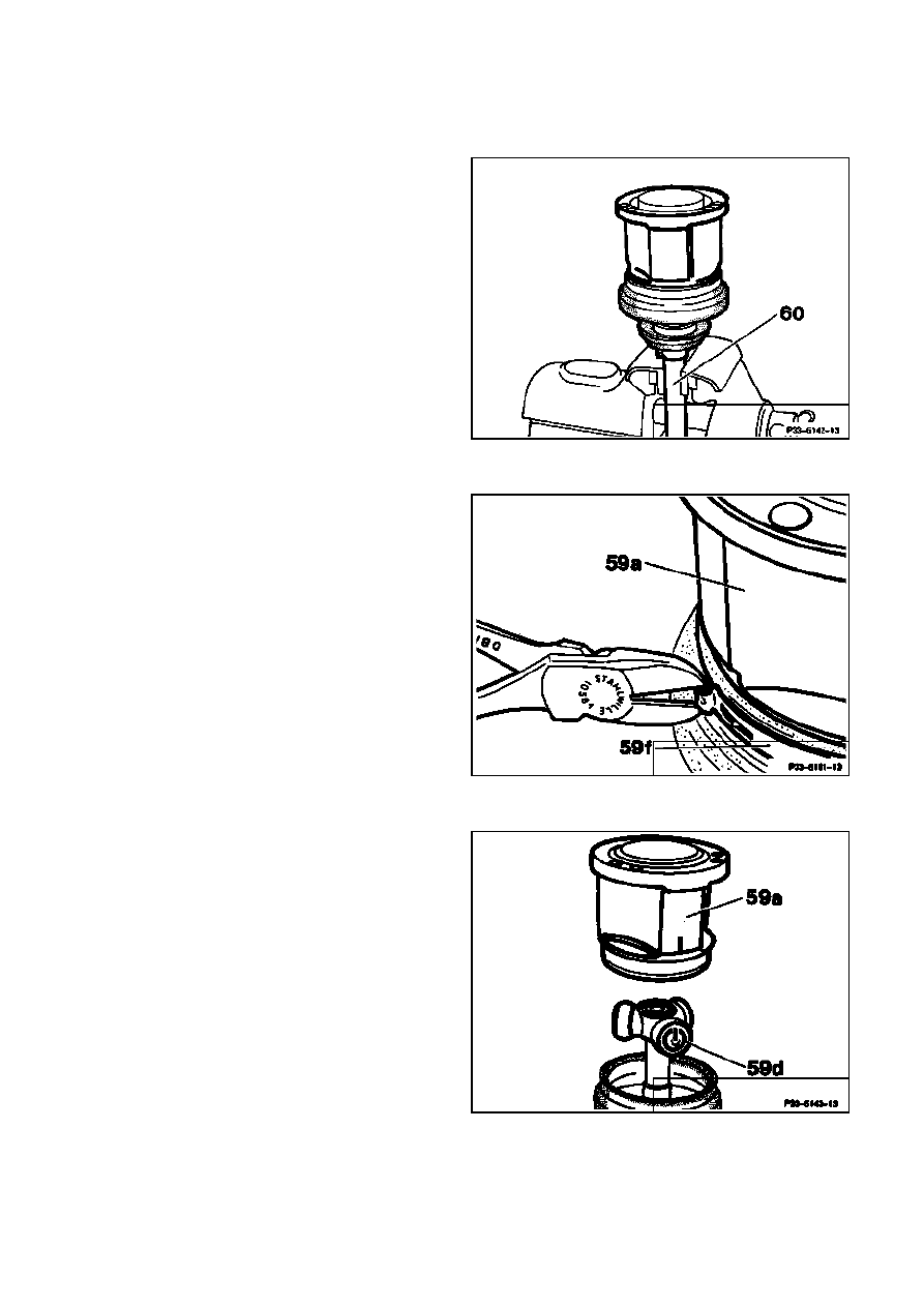
1
Clamp front axle shaft (60) vertically in the
vise using clamping jaws, with the tripod inner
joint upwards.
P33-5142-13
2
Remove hose clamp (59f) on tripod joint
casing (59a) using side cutters.
P33-5161-13
3
Mark position of tripod spiders (59d) in
relation to tripod joint casing (59a), remove
joint casing.
P33-5143-13
Strona 3/7
© Daimler AG, 21.07.12, G/03/09 / ra334m1240660x / 0660 - Replacment of the rubber bellows on the front axle shaft Drive 4MATIC
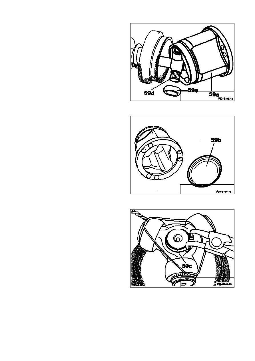
M
Ensure that the tripod joint rollers, which are
supported on needle bearings, (59e) do not slip
off the spigot on the tripod joint spider (59d).
P33-5160-13
4
Remove end cover (59b).
P33-5144-13
5
Clean grease off joint and use wire or
adhesive tape to secure the tripod joint
rollers supported on needle bearings, to
prevent them falling out. Each joint roller is
supported on 32 needles.
6
Remove circlip (59c).
P33-5145-13
Strona 4/7
© Daimler AG, 21.07.12, G/03/09 / ra334m1240660x / 0660 - Replacment of the rubber bellows on the front axle shaft Drive 4MATIC
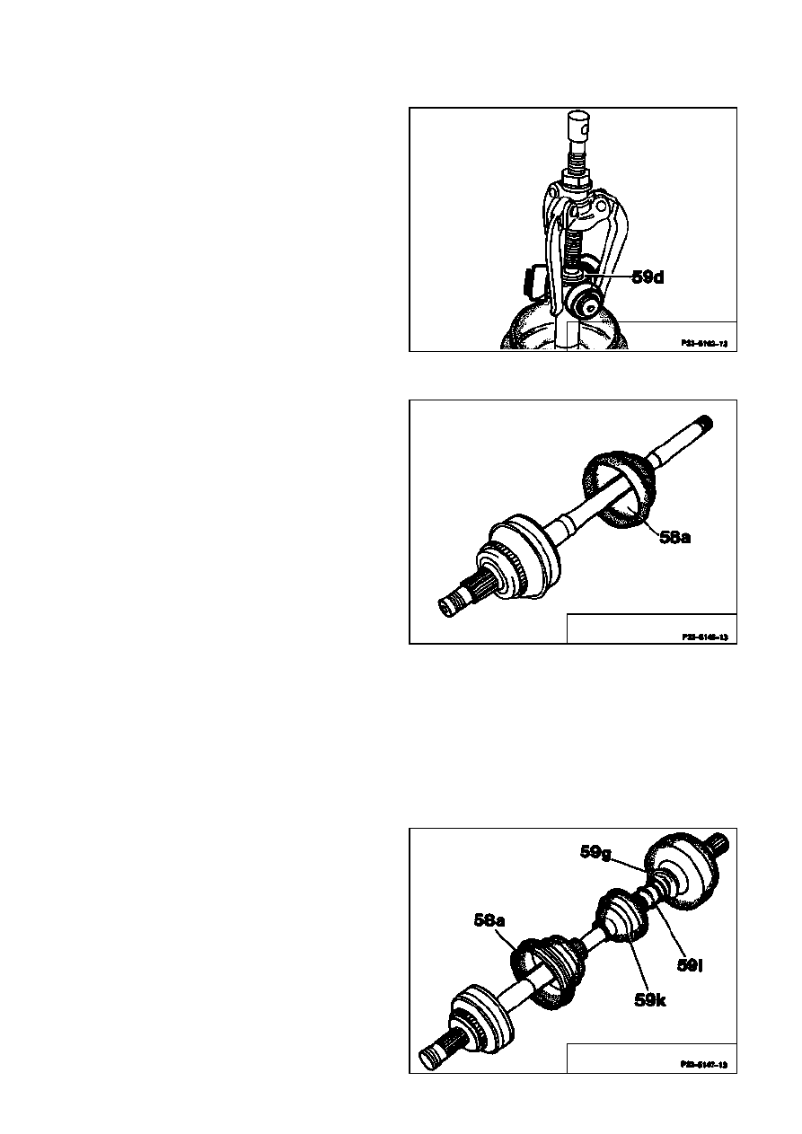
7
Extract tripod spider (59d) from front axle
shaft using three-arm puller.
P33-5162-13
8
If required remove additional hose clamps,
detach relevant rubber bellows and bush and
remove.
Remove the outer rubber bellows (58a) via the
dismantled side of the front axle shaft, if
necessary. Ensure that none of the grease
escapes and that no dirt gets into the inside of
the joint. Wipe off the grease remaining in the
inside of the rubber bellows and transfer to the
joint.
P33-5146-13
9
Check parts for damage or wear, replace if
required.
Assembly
10 Push rubber bellows (58a, 59g, 59k) and
bush (59i) onto front axle shaft.
11 Assemble hose clamps.
P33-5147-13
Strona 5/7
© Daimler AG, 21.07.12, G/03/09 / ra334m1240660x / 0660 - Replacment of the rubber bellows on the front axle shaft Drive 4MATIC
M
Ensure correct seating of bush (59i) at the
connection of both inner rubber bellows (59g,
59k).
P33-5148-13
12 Push tripod spider (59d) with the flat side
(arrow) towards the circlip up to the stop on
the spline section.
13 Detach circlip.
14 Press end cover (59b) onto the tripod joint
casing (59a).
15 Fill joint with grease.
M
P33-5163-13
Only use the specified quantity of approved
lubricants.
16 Insert joint casing (59a) on tripod spider
(59d), noting the applied marking.
P33-5143-13
Strona 6/7
© Daimler AG, 21.07.12, G/03/09 / ra334m1240660x / 0660 - Replacment of the rubber bellows on the front axle shaft Drive 4MATIC
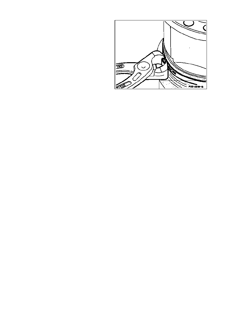
17 Slide rubber bellows into correct position and
tighten hose clamp using assembly pliers. At
the same time ensure that the hose clamp
contacts evenly.
P33-2219-13
Strona 7/7
© Daimler AG, 21.07.12, G/03/09 / ra334m1240660x / 0660 - Replacment of the rubber bellows on the front axle shaft Drive 4MATIC
Wyszukiwarka
Podobne podstrony:
Wymiana osłony przegubu, Samochody i motoryzacja, silniki spalinowe, Serwis
Wymiana oslony przegubu w Felicii, Skoda Felicja
MK7 Wymiana oslony przegubu Nieznany
Wymiana osłony przegubu
Wymiana słony przegubu, AUDI 80 B4
NissanPrimeraP10 wymiana oslon przegubow
C5 (X7) B2FH0104P0 40 06 03 2014 Wymiana Osłony mieszkowe półosi napędowych
Projekt 6 Sprawdzenie i wymiana przegubów kulowych drążków kierowniczych
Wymiana przednich klocków w BX
Wymiana przegubu zewnętrznego
407 B3CG2GK1 Demontaż Montaż Przegub elastyczny przednie
Renault Scenic K4M Wymiana gum drążka stabilizatora przedniego
[4matic] Demontaż półosi przedniej
audi TT wymian zarowek przednich kierunkowskazow
CC WYMIANA WAHACZA PRZEDNIEGO
C5 (X7) B3CG010GP0 3 25 11 2008 Demontaż montaż Górny przegub przedniej zwrotnicy
Renault Scenic K4M Wymiana klocków hamulcowych przednich
407 B3CG1CK1 Demontaż Montaż Górny przegub przedniej zwr
więcej podobnych podstron