
QXDM Software Users Guide
80-V1241-21 Rev. A
November 21, 2001
Restricted Distribution:
This document contains
critical information about QUALCOMM products and
may not be distributed to anyone that is not an
employee of QUALCOMM without the approval of
Configuration Management.
QUALCOMM Incorporated
5775 Morehouse Dr.
San Diego, CA 92121-1714
U.S.A.

ii
QUALCOMM Proprietary
80-V1241-21 Rev. A
QUALCOMM Incorporated
5775 Morehouse Dr.
San Diego, CA 92121-1714
U.S.A.
Copyright © 2000, 2001 QUALCOMM Incorporated. All rights reserved.
All data and information contained in or disclosed by this document is confidential and proprietary information of
QUALCOMM Incorporated, and all rights therein are expressly reserved. By accepting this material, the recipient agrees
that this material and the information contained therein is held in confidence and in trust and will not be used, copied,
reproduced in whole or in part, nor its contents revealed in any manner to others without the express written permission
of QUALCOMM Incorporated.
Export of this technology may be controlled by the United States Government. Diversion contrary to U.S. law
prohibited.
Restricted Distribution: This document contains critical information about QUALCOMM products
and may not be distributed to anyone that is not an employee of QUALCOMM without the
approval of Configuration Management.
QUALCOMM is a registered trademark and registered service mark of QUALCOMM Incorporated. Other product and
brand names may be trademarks or registered trademarks of their respective owners.
Information in this document is preliminary and subject to change and does not represent a commitment on the part of
QUALCOMM Incorporated.
QXDM Software Users Guide
80-V1241-21 Rev. A
November 21, 2001

80-V1241-21 Rev. A
QUALCOMM Proprietary
iii
Contents
3 Communication Parameters ............................................................. 3-1
4.4.3 Message view and Autoscroll button....................................................4-11

Contents
QXDM Software Users Guide
iv
QUALCOMM Proprietary
80-V1241-21 Rev. A
8.3.1 Splitter Window Overview of the Property Editor................................. 8-2
8.3.2 Category Display of the Property Editor................................................ 8-3
8.3.3 Property Display of the Property Editor................................................. 8-4

QXDM Software Users Guide
Contents
80-V1241-21 Rev. A
QUALCOMM Proprietary
v
10 DWARF Server ............................................................................... 10-1
12 QXDM Command-prompt Functions............................................ 12-1
13 Temporal Analyzer ........................................................................ 13-1
13.3 Transmit/Receive (Tx/Rx) Adjusted Power display........................................13-3
13.5 Frame Types (old Tx/Rx Vocoder Rate) display.............................................13-5
14 Application Screens ...................................................................... 14-1
15 Troubleshooting ............................................................................ 15-1

Contents
QXDM Software Users Guide
vi
QUALCOMM Proprietary
80-V1241-21 Rev. A

QXDM Software Users Guide
Contents
80-V1241-21 Rev. A
QUALCOMM Proprietary
vii
Figures
→ Communications → Configuration tab ......................................3-1
→ Communications → Timeout Settings tab .................................3-2
→ Communications → Statistics tab ..............................................3-3
→ Dip Switch dialog ......................................................................4-1
→ Settings → Messages dialog ......................................................4-2
→ Settings → Preferences dialog ...................................................4-3
→ SIA Remote Control dialog........................................................4-4
→ Event Options.............................................................................7-5
Figure 13–5 Frame Types (old Tx/Rx Vocoder Rate) display......................................13-5
→ Configuration.......................................................13-7

Contents
QXDM Software Users Guide
viii
QUALCOMM Proprietary
80-V1241-21 Rev. A
Tables

80-V1241-21 Rev. A
QUALCOMM Proprietary
1-1
1 Introduction
1.1 Purpose
1
The QUALCOMM Extensible Diagnostic Monitor (QXDM) provides a diagnostic client for dual-
2
mode subscriber station (DMSS) software. Its interface is based on the mobile diagnostic monitor
3
(MDM) and the CDMA air interface tester (CAIT). It was developed to provide a rapid prototyping
4
platform for new diagnostic clients and diagnostic protocol packets. QXDM provides a graphical user
5
interface (GUI) that displays data retrieved from DMSS.
6
1.2 Scope and intended audience
7
This user guide is intended for users of QXDM who need to know how to install, use, and understand
8
the information provided by QXDM. Many features in QXDM are documented elsewhere. Applicable
9
documents are referenced in Table 1-2, however, most features are documented in the Compatibility
10
Notes for the software release in which the feature was added. The following is an overview of what
11
is covered in this guide:
12
■
Installation
13
■
Physical connectivity
14
■
Communication parameters
15
■
QXDM screens
16
QXDM also provides some advanced features designed for development:
17
■
DWARF server
18
■
Perl script interface
19
1.3 Conventions
20
Function declarations, function names, type declarations, and code samples appear in a different font.
21
For example:
#include
22
Code variables appear in angle brackets. For example:
<number>
23
Shading indicates content that has been added or changed in this revision of the document.
24

Introduction
QXDM Software Users Guide
1-2
QUALCOMM Proprietary
80-V1241-21 Rev. A
1.4 Revision history
1
The revision history for this document is shown in Table 1-1.
2
Table 1-1 Revision history
3
Document number
Date
Description
80-V1241-1 Rev. –
Mar 2000
Initial release
80-V1241-3 Rev. –
Apr 2000
Added chapters: application screens, troubleshooting. Added status
bar description.
Note: There was no 80-V1241-2. The number was skipped
intentionally in accordance with internal administrative tracking
practices.
80-V1241-4 Rev. –
Apr 2000
Added temporal analyzer information. Updated application screens
chapter.
80-V1241-9 Rev. –
Jun 2000
Added GPS feature. Added sections and screens: RLP throughput
display, quick paging channel, RLP3 statistics, NV items. Updated
chapters: installation, logging and events, application screens.
Note: There was no 80-V1241-5 through 80-V1241-8. The numbers
were skipped intentionally in accordance with internal administrative
tracking practices.
80-V1241-14 Rev. –
Aug 2000
Added sections and screens: IS-2000 supplemental channel mux
parameters, retrievable parameters, streaming configuration, simple
test data services, gpsOne.
Updated chapters: overview of screens, application screens.
Updated screens: three splitter screen, NV items.
Note: There was no 80-V1241-10 through 80-V1241-13. The numbers
were skipped intentionally in accordance with internal administrative
tracking practices.
80-V1241-15 Rev. –
Sep 2000
Added sections and screens: pilot sets display, temporal analyzer
configuration, log priorities, GPS statistics, factory test mode.
Updated properties chapter. Updated sections and/or screens: fast
forward power control, IS-2000 supplemental channel mux parameters,
retrievable parameters, simple test data services, gpsOne. Updated
scope and intended audience, reference documents.
Removed streaming configuration section.
80-V1241-17 Rev. –
Nov 2000
Renamed overview of screens chapter to display overview chapter.
Added sections to the chapter: options (with screens), property views.
Added sections and screens: full test data services, events,
Bluetooth™ logs.
Updated logging and events chapter and screen. Updated sections:
property support tools, gpsOne, GPS statistics. Updated screen:
simple test data services. Updated reference documents.
Note: There was no 80-V1241-16. The number was skipped
intentionally in accordance with internal administrative tracking
practices.
80-V1241-18 Rev. –
Dec 2000
Added gpsOne reference document. Updated sections and/or screen:
gpsOne, GPS statistics. Updated reference documents.
80-V1241-19 Rev. –
Feb 2001
Added property editor chapter. Updated properties chapter. Updated
reference documents.

QXDM Software Users Guide
Introduction
80-V1241-21 Rev. A
QUALCOMM Proprietary
1-3
Document number
Date
Description
80-V1241-20 Rev. –
Mar 2001
Added chapters: Events, QXDM command prompt functions.
Updated Perl script interface chapter.
Updated screens: mux traffic channel statistics, mux traffic channel
and secondary statistics, quick paging channel statistics, fast forward
power control logs, RLP3 statistics log, NV items, IS-2000 SCH mux
parameters, retrievable parameters, BT logs, Bluetooth™ logs.
80-V1241-21 X1
Jun 2001
Updated Sections 4.1-Options, 4.4.3-Message view and autoscroll
button, and 7.2.1-Scrolling display.
Updated screens: RLP3 Statistics Log, IS-2000 SCH MUX
Parameters, Bluetooth™ Logs, Full Test Data Services, gpsOne,
Simple Test Data Services.
Added screens Active Set Information and the following HDR screens:
Air Link Summary, Fingers Data, Forward Link Statistics, GEN TA,
Reverse Link Statistics, RLP Statistics, RX Statistics, SEARCH Status,
Status, Temporal Analyzer, and the following WCDMA screens: AGC,
Block Error Rate, Downlink TM Channel Parameters, Layer 1 State,
Layer 4 Connection Mgmt, MAC Channel Mapping, MAC Parameters,
Mobility Management, Physical Channel, RLC DL UM Channel
Parameters, RLC UL UM Channel Parameters, RRC Status, Temporal
Analyzer, TFCS Downlink, Transport Channels, Uplink TM Channel
Parameters.
Note: The document number for this revision has been changed to
adhere to current document numbering standards.
80-V1241-21 X2
Sep 2001
Rewrote chapter 11 – Script Interface.
Updated Annotate Logfile documentation, section 4.1. Updated ALIEM
documentation, section 4.2.
Updated Chapter 14 screens: Full Test Data Service, Simple Test Data
Service.
Removed Chapter 14 Sections: IS-2000 SCH MUX Parameters,
WCDMA L4 Connection Management.
Added Chapter 14 Sections: Mux Statistics, WCDMA CS and PS
Connection Management, WCDMA NAS Error.
80-V1241-21 Rev. A
Nov 2001
Rewrote chapter 14 – Application Screens.
Updated Property Support Tools documentation, section 6.6 and 6.6.1.
Added documentation to Property Database sections 8.1 and 8.2.
Updated document version numbers and dates in Section 1.5.
The revision numbering system has been changed for internal tracking
purposes only.
1
2
Introduction
QXDM Software Users Guide
1-4
QUALCOMM Proprietary
80-V1241-21 Rev. A
1.5 References
1
Reference documents, which may include QUALCOMM, standards, and resource documents, are
2
3
Table 1-2 Reference documents
4
Ref. Document
QUALCOMM
1
CDMA DMSS Serial Data Interface Control Document
80-V1294-1 X9
Sep 2001
2
Factory Test Mode Application Note
CL93-V1974-1 X3
Mar 2001
3
gpsOne™ Position Determination Messaging and
Parameters
80-V0726-1 X6
Jan 2001
4
Serial Interface Control Document for W-CDMA
80-V2708-1 X2
Oct 2001
5
1.6 Technical assistance
6
For assistance or clarification on information in this guide, email QUALCOMM CDMA
7
Technologies at asicapps@qualcomm.com.
8
1.7 Acronyms
9
The following acronyms are used throughout this guide:
10
11
CAIT
CDMA air interface tester
CDMA
Code division multiple access
DLL
Dynamic link library
DMSS
Dual-mode subscriber station
ELF
Executable and linking format
ESN
Electronic serial number
FER Frame
error
rate
FFA Form-fit
accurate
F-FCH
Forward fundamental channel
F-SCCH
Forward supplemental code channel
F-SCH
Forward supplemental channel
FTM Factory
test
mode
GPS
Global positioning system

QXDM Software Users Guide
Introduction
80-V1241-21 Rev. A
QUALCOMM Proprietary
1-5
GUI
Graphical user interface
HTML
Hypertext markup language
MDM Mobile
diagnostic
monitor
MSM
Mobile station modem
NV Nonvolatile
memory
PDE
Position determination entity
PN Pseudorandom
noise
QXDM
QUALCOMM extensible diagnostic monitor
R-DCCH
Reverse dedicated control channel
R-FCH
Reverse fundamental channel
RLP Radio
link
protocol/processor
R-SCH Reverse
supplemental
channel
SIA
Sensor interface application
SILK
Structure Iteration Language toolkit
SURF
Subscriber unit reference platform
1
2

Introduction
QXDM Software Users Guide
1-6
QUALCOMM Proprietary
80-V1241-21 Rev. A
1
2

80-V1241-21 Rev. A
QUALCOMM Proprietary
2-1
2 Installation
2.1 Required hardware and software
1
QXDM is designed to be installed and run on a workstation running Microsoft
Windows NT
4.0 or
2
Windows 98
.
3
NOTE
An installation of Microsoft Internet Explorer 5.0 is required to run QCDM.
QXDM can be run on a Microsoft
Windows 95
workstation but requires an installation of DCOM
4
for Windows 95. Both Internet Explorer
Version 5.0 and DCOM for Windows 95 are available on
5
the QXDM installer CD. A license file is also required, which enables QXDM to run for a specified
6
period of time.
7
2.2 Installing QXDM
8
The QXDM software is provided either over the network or on CD-ROM.
9
This installer loads the user release of QXDM, which includes the QXDM client components
10
(application binaries, DLLs, HTML files, property files, and so on) and the server components
11
(Build ID and DWARF servers) on the user’s machine.
12
A variant of this installer is the QXDM server installer, which installs only the QXDM server
13
components on a designated build server machine.
14
The following procedure explains the user release installer only.
15
To install QXDM:
16
1. From the Windows desktop, select Start
→Run→Setup.exe.
17
2. Click
OK
.
18
3. By default, QXDM will be installed on your machine at c:\Program Files\qualcomm\qxdm.
19
The installer will allow you to change the installation directory to one of your choosing.
20
The installer creates a QXDM folder in your Start menu. QXDM can be run from your Start menu by
21
selecting Start
→ Programs → QXDM → QXDM.
22
Installation
QXDM Software Users Guide
2-2
QUALCOMM Proprietary
80-V1241-21 Rev. A
2.3 Installing the license file
1
A license file is provided which enables QXDM to run for a specified period of time. The filename is
2
license.txt and must be placed in the bin directory where QXDM was installed (for example,
3
C:\Program Files\qualcomm\qxdm\bin\license.txt). The license file is a text file that can be viewed
4
using any editor such as NotePad. It contains a readable start date and end date followed by two or
5
more lines of encrypted data. To illustrate, the following license file enables QXDM to run from
6
February 21, 2000 to March 22, 2000.
7
File: license.txt
8
Start Date: 2000 02 21
9
End Date: 2000 03 22
10
99 61 55 f5 19 33 ec 1d 15 eb 3d a2 76 e6 a8 40
11
da c0 b7 ea c5 67 04 3a 0b d6 0d d2 87 dc cd 40
12
Making changes to license.txt will render it invalid. If you need a new license file, contact
13
QUALCOMM Technical Support by email at asicapps@qualcomm.com.
14
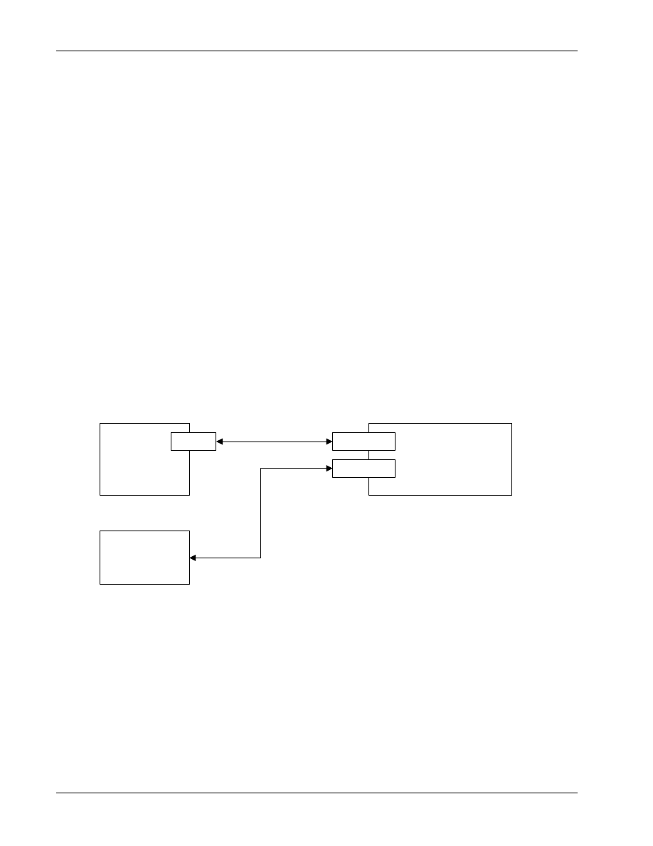
2.4 Physical connectivity
15
QXDM connects to a phone or SURF using a serial cable to a COM port on your PC, as depicted in
16
17
SURF
PC running QXDM
FFA
UART
COM Port
COM Port
RS-232
18
Figure 2–1 Physical connectivity
19
20
80-V1241-21 Rev. A
QUALCOMM Proprietary
3-1
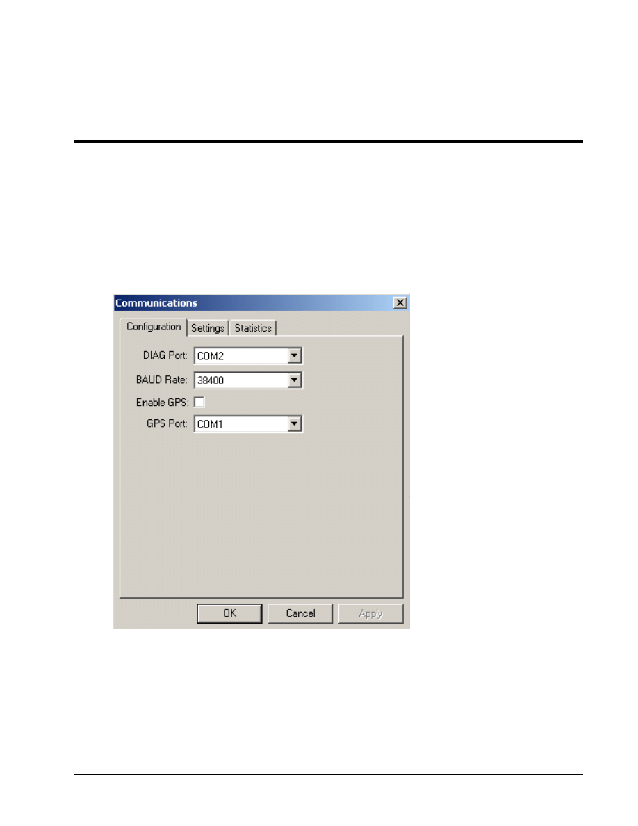
3 Communication Parameters
QXDM communication parameters are configured using the Options
→Communications dialog. The
1
Communications dialog allows you to configure the COM port that will be used by QXDM, as well
2
as the baud rate and timeout settings. Figure 3–1 illustrates the configuration.
3
4
Figure 3–1 Options
→ Communications → Configuration tab
5
6
To use a connected GPS Receiver, select which COM port your GPS receiver is connected to, then
7
select the Enable GPS check box. QXDM will start collecting GPS information from the GPS
8
receiver.
9
Communication Parameters
QXDM Software Users Guide
3-2
QUALCOMM Proprietary
80-V1241-21 Rev. A
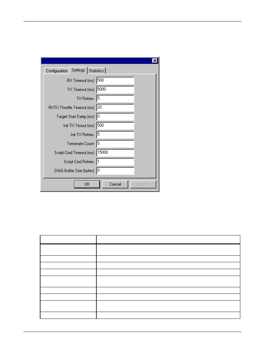
The timeout settings dialog is accessible via the Options
→ Communications → Settings tab. Figure
1
3–2 illustrates the dialog.
2
3
Figure 3–2 Options
→ Communications → Timeout Settings tab
4
5
Table 3-1 describes the timeout settings.
6
Table 3-1 Timeout settings
7
Timeout setting
Description
RX Timeout (ms)
Time QXDM waits without receiving a message before determining that the
phone is disconnected.
TX Timeout (ms)
Time QXDM waits for a reply from the phone.
TX Retries
Number of times to retry waiting for a reply from the phone.
RXTX Throttle Timeout (ms)
Time between sends.
Target Start Delay (ms)
Time to wait after establishing a connection with the phone before sending the
first request.
Init TX Timeout (ms)
Time to wait for a reply from the phone when reconnecting.
Init TX Retries
Number of times to retry reconnecting to the phone.
Terminate Count
Number of receive timeouts before determining that the phone is
disconnected.
Script Cmd Timeout (ms)
Time to wait before timing out for script commands (command line).
QXDM Software Users Guide
Communication Parameters
80-V1241-21 Rev. A
QUALCOMM Proprietary
3-3
Timeout setting
Description
Script Cmd Retries
Number of retries before giving up sending script commands (command line).
DIAG Buffer Size (bytes)
Unused.
1
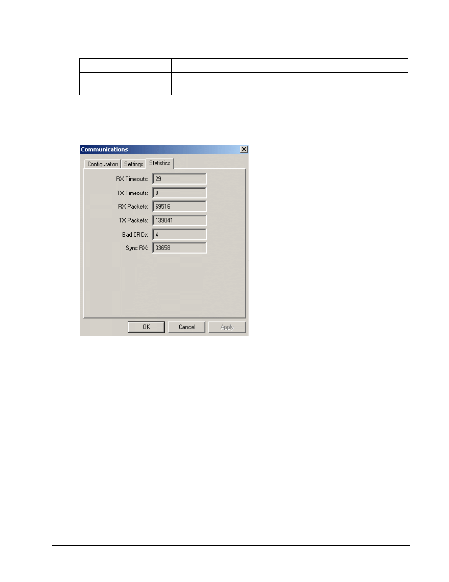
The statistics display is accessible via the Options
→ Communications → Statistics tab. Figure 3–3
2
illustrates the display.
3
4
Figure 3–3 Options
→ Communications → Statistics tab
5
6

Communication Parameters
QXDM Software Users Guide
3-4
QUALCOMM Proprietary
80-V1241-21 Rev. A
1
2
80-V1241-21 Rev. A
QUALCOMM Proprietary
4-1
4 Display Overview
QXDM uses a single-document interface with multiple views.
1
4.1 Options
2
Communications
3
See Chapter 3 for more information.
4
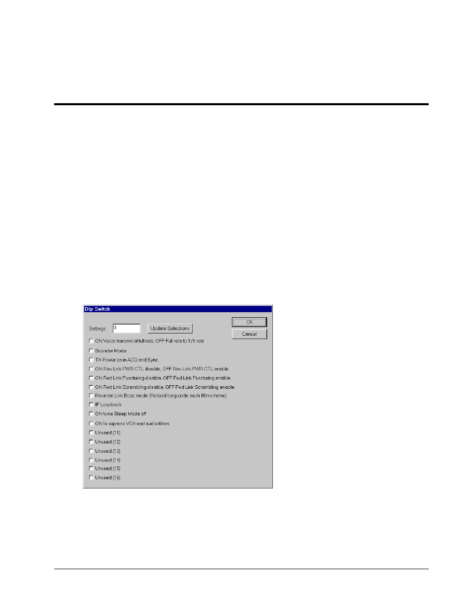
Dip switches
5
The Dip Switch dialog allows you to configure supported dip switch settings, as shown in Figure 4–1.
6
7
Figure 4–1 Options
→ Dip Switch dialog
8
Display Overview
QXDM Software Users Guide
4-2
QUALCOMM Proprietary
80-V1241-21 Rev. A
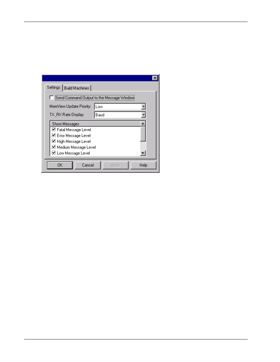
Settings
1
The Settings display, shown in Figure 4–2, allows you to control which messages are displayed to the
2
Messages <F3> screen, configure build machine settings, and set various preferences. See Section
3
10.4 for information on configuring build machines.
4
5
Figure 4–2 Options
→ Settings → Messages dialog
6
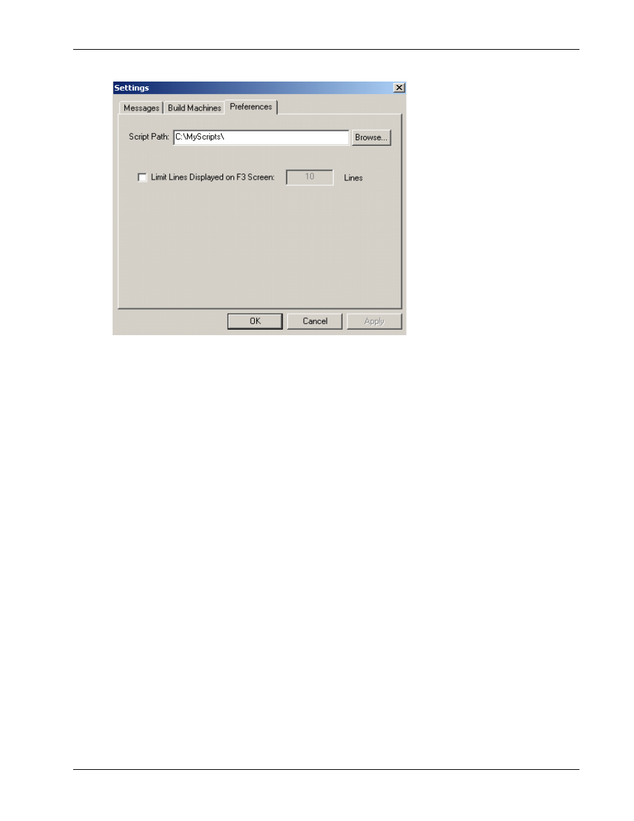
Settings
→ Preferences
7
This screen allows you to set various personal preferences. You can override the default path from
8
which to run scripts (the default is C:\Program Files\Qualcomm\QXDM\bin). It is also possible to
9
enter a path directly in the command line box. You can also establish a limit on how many lines are
10
displayed on the Messages <F3> screen.
11
QXDM Software Users Guide
Display Overview
80-V1241-21 Rev. A
QUALCOMM Proprietary
4-3
1
Figure 4–3 Options
→ Settings → Preferences dialog
2
Licensing
3
The Licensing command allows you to view your current QXDM license status.
4
Logging options
5
This dialog allows you to set the log mask. See Chapter 5 for more information.
6
Event options
7
The Event Options command allows you to configure the default settings used to display events. See
8
Section 7.3 for more information.
9
Edit annotation list
10
The Edit Annotation List command allows you to select predefined comments to annotate log
11
messages.
12
Annotate log file
13
Use this command to insert annotations to the log file. This command is enabled only during logging.
14
15
Display Overview
QXDM Software Users Guide
4-4
QUALCOMM Proprietary
80-V1241-21 Rev. A
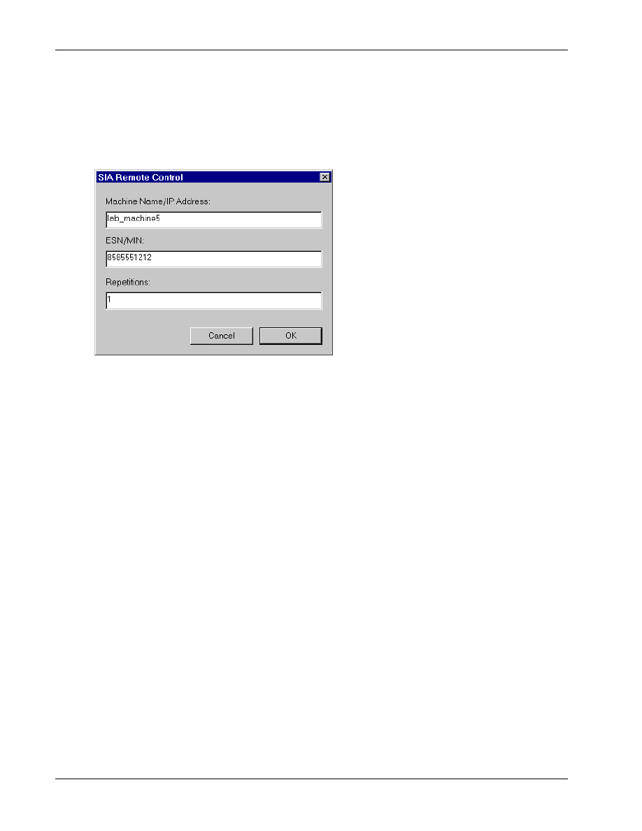
SIA remote control
1
The SIA (Sensor Interface Application) Remote Control dialog shown in Figure 4–4, allows you to
2
start a remote session with a Position Determination Entity (PDE).
3
4
Figure 4–4 Options
→ SIA Remote Control dialog
5
Logging
6
The Logging command enables or disables (toggles) logging to a file.
7
Event reporting
8
The Event Reporting command enables or disables (toggles) display of events.
9
Flush F3 Screen
10
This command erases all messages from the screen.
11
12
QXDM Software Users Guide
Display Overview
80-V1241-21 Rev. A
QUALCOMM Proprietary
4-5
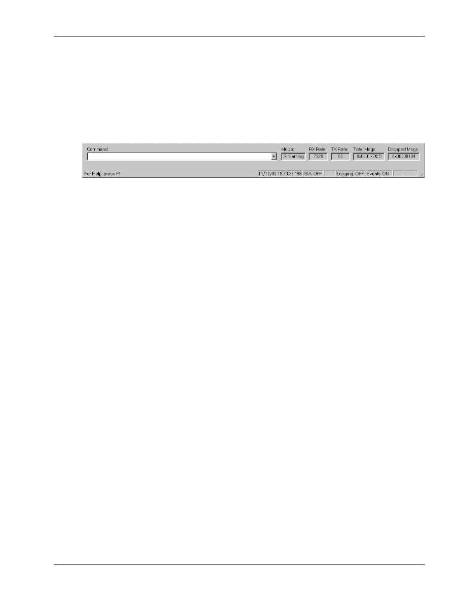
4.2 Status bar
1
The status bar, shown in Figure 4–5, contains status information about the current session, as well as
2
a command interface.
3
4
Figure 4–5 QXDM status bar
5
Command Box
6
You can type commands into the command box. Most DM script commands are supported. DM and
7
Perl scripts can be started from the command box by typing run script_file_name, where
8
script_file_name is the name of the DM script (.scr extension) or a Perl script (.pl extension). When
9
launching a script using the run command, it may be necessary to specify the fully qualified path
10
name of the file. Launching Perl scripts from the command box requires that Perl be installed and
11
associated with the .pl file extension. A Command Output screen displays the output, and a Script
12
Help page is available to help with DM script commands. See Section 4.4 for information on how to
13
display the Command Output and Script Help screens.
14
Mode
15
This displays Streaming when a phone with a streaming build is connected, or Query when a phone
16
with a nonstreaming build is connected.
17
RX rate
18
The rate at which data is received from the phone. It is displayed in BAUD, bits per second, or bytes
19
per second depending on the option selected on the Options
→ Settings → Messages dialog (see
20
21
TX rate
22
The rate at which data is sent to the phone. It is displayed in BAUD, bits per second, or bytes per
23
second depending on the option selected on the Options
→ Settings → Messages dialog (see
24
25
Total msgs
26
Total number of messages reported by the phone.
27
Dropped msgs
28
Total number of dropped messages reported by the phone.
29

Display Overview
QXDM Software Users Guide
4-6
QUALCOMM Proprietary
80-V1241-21 Rev. A
ALIEM
1
QXDM provides a TCP Socket interface for the WCDMA AL1 Emulator (ALIEM) to send Diag
2
commands to the connected SURF/Mobile through QXDM and receive the response. This Socket
3
interface can also be used by clients other than the ALIEM. On startup, QXDM sets up a TCP listener
4
on address 5999. The Status Bar in the bottom displays the state of the QXDM-ALIEM listener.
5
Initially, the display is ALIEM: Ready. When a client connects to the socket, the display changes to
6
ALIEM: Connected. Clients send Diag request packets (as explained in the DMSS ICD) through the
7
Socket. The packet format is as follows:
8
9
struct ALIEMPacket
10
{
11
uint16 len;
12
uint8 data [min(len, 1620)];
13
}
14
15
QXDM passes the request packet to the SURF/Mobile and returns the response packet through the
16
socket. The packet format is the same as the one for the request packet.
17
SIA
18
This displays the SIA Remote Control status.
19
GPS
20
GPS status (displays GPS if the GPS is enabled, otherwise displays nothing).
21
Logging: XXX
22
Logging status OFF or ON.
23
Events: XXX
24
Event reporting OFF or ON.
25
CAPS
26
Caps lock status.
27
NUM
28
Num lock status.
29
30
QXDM Software Users Guide
Display Overview
80-V1241-21 Rev. A
QUALCOMM Proprietary
4-7
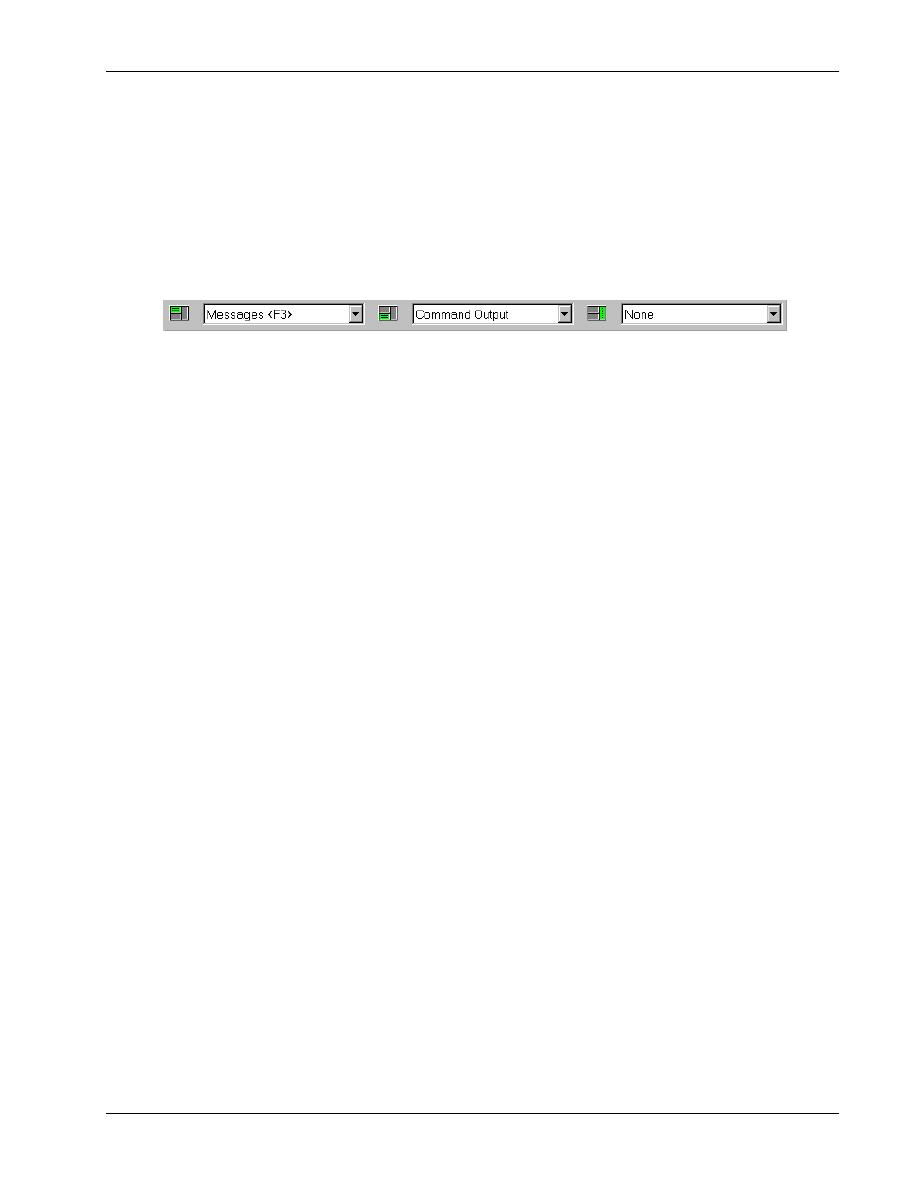
4.3 Multiple views
1
Splitter windows are used to display one or more views. Figure 4–6 illustrates the splitter view bar.
2
Views are selected using the splitter view bar to split the main view screen into three primary views
3
as depicted by the green shaded view icons. See Chapter 14 for more information on the pages loaded
4
using the splitter view bar.
5
6
Figure 4–6 Splitter view bar
7
The splitter view bar has three pull-down menus. The left menu will always be displayed, and you can
8
choose whether to display the other two.
9
Selections from the left menu, such as Messages <F3>, will display as a top view. Selections from the
10
middle menu, such as Command Output, Memory Viewer, and Temporal Analyzer, will display as a
11
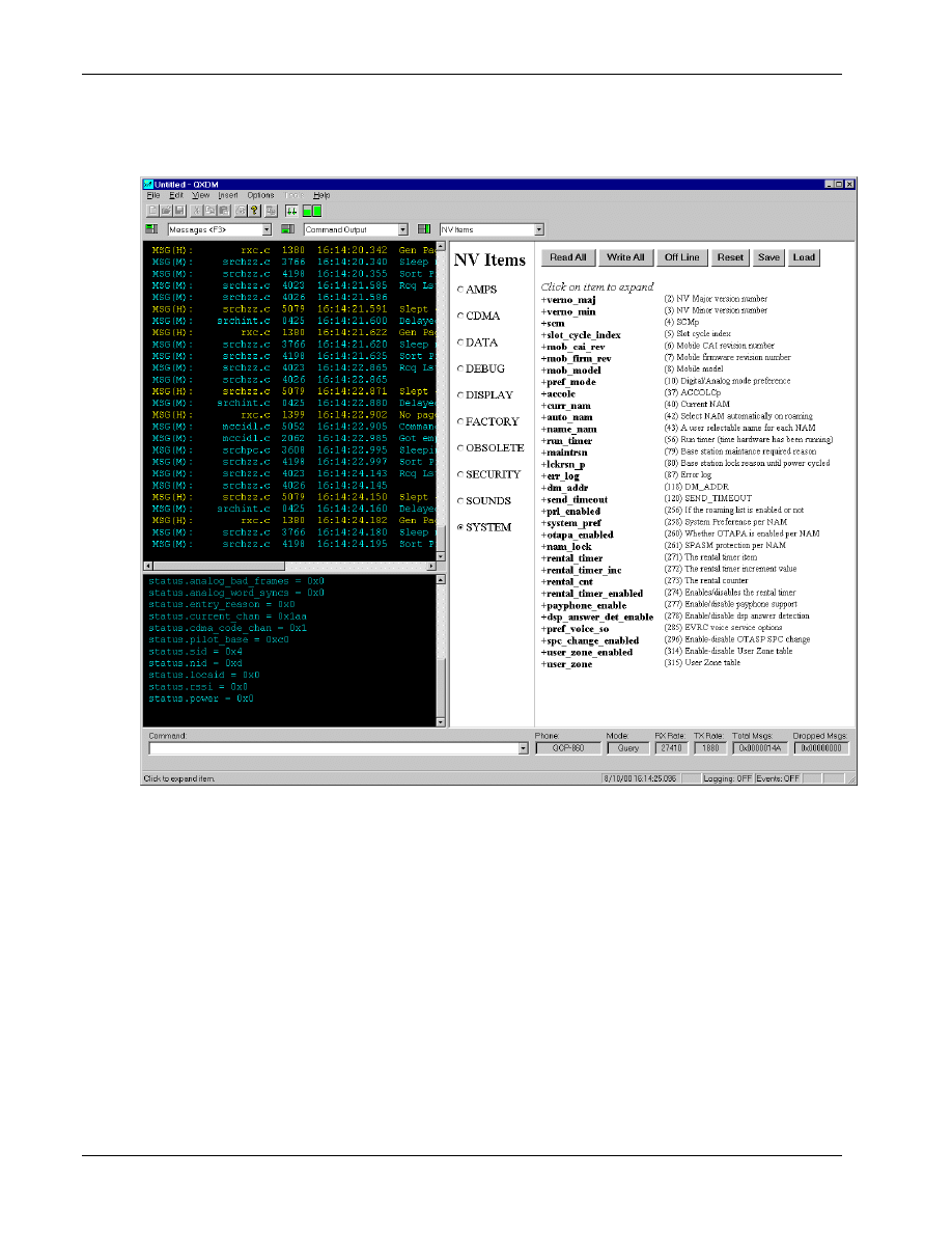
bottom view. Selections from the right menu, such as NV Items, will display as a right-side view.
12
Examples of splitter view bar selections and the resulting splitter screens are shown in the following
13
figures.
14
Display Overview
QXDM Software Users Guide
4-8
QUALCOMM Proprietary
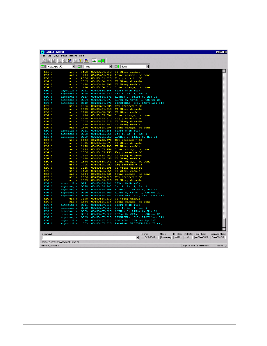
80-V1241-21 Rev. A
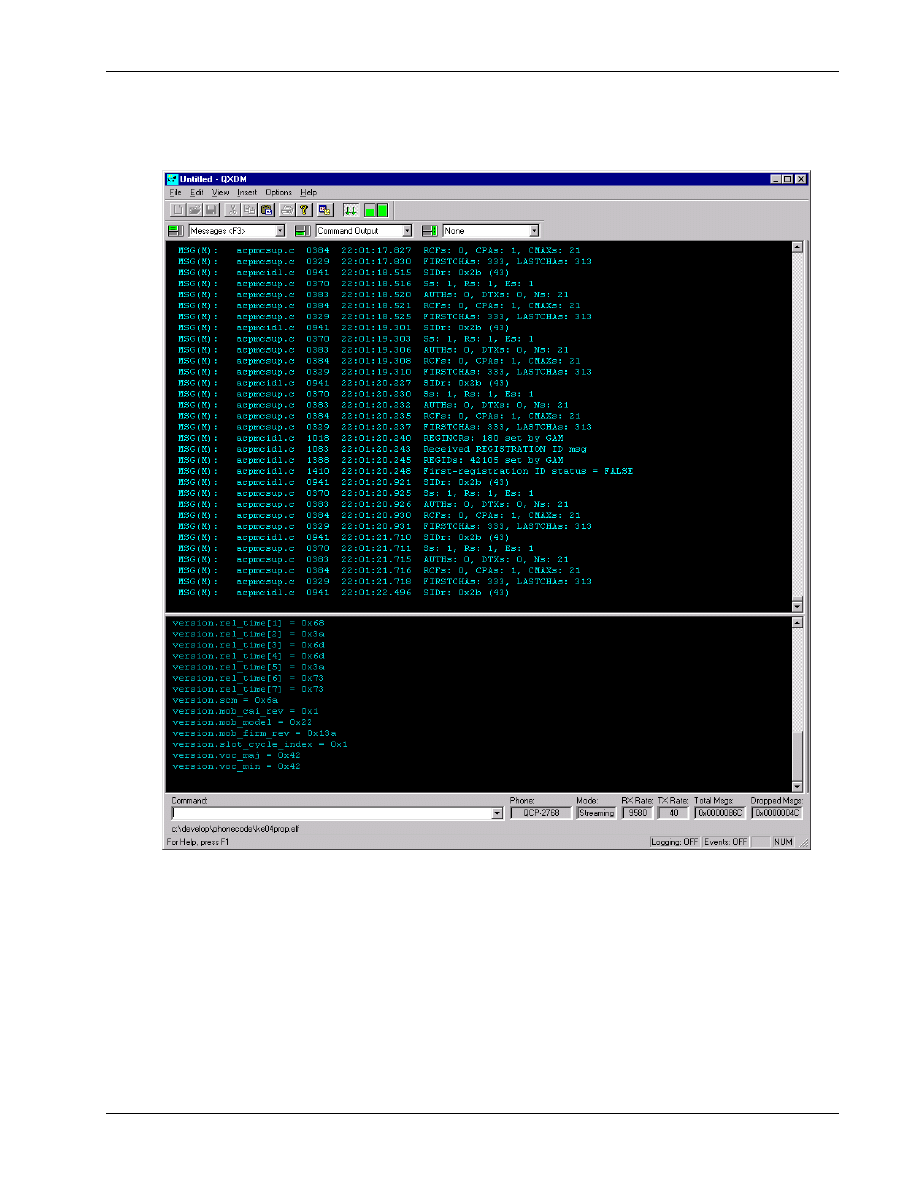
Figure 4–7 is an example of one splitter screen.
1
2
Figure 4–7 Example of one splitter screen
3
QXDM Software Users Guide
Display Overview
80-V1241-21 Rev. A
QUALCOMM Proprietary
4-9
Figure 4–8 is an example of two splitter screens.
1
2
Figure 4–8 Example of two splitter screens
3
Display Overview
QXDM Software Users Guide
4-10
QUALCOMM Proprietary
80-V1241-21 Rev. A
Figure 4–9 is an example of three splitter screens.
1
2
Figure 4–9 Example of three splitter screens
3
4

QXDM Software Users Guide
Display Overview
80-V1241-21 Rev. A
QUALCOMM Proprietary
4-11
4.4 Additional views
1
The Command Output and Messages <F3> displays of QXDM show information from the SURF or
2
FFA and use rich-edit text views, which provide text editing capabilities. Other properties are
3
displayed using HTML browser views.
4
To view a page, select it from the drop-down menu associated with the desired splitter view and click
5
6
4.4.1 Command Output view
7
To view output from commands entered on QXDM’s command line, select Command Output from
8
the middle menu.
9
4.4.2 Script Help view
10
You can select Script Help from any of the three menus.
11
4.4.3 Message view and Autoscroll button
12
Messages from the FFA or SURF are displayed in this view. To view Messages, select
13
Messages <F3> from the left menu. Message rate, priority, and filtering are configured using the
14
Options
→ Settings → Messages dialog. In the toolbar there is an Autoscroll button
that will
15
enable or disable auto scrolling without affecting addition of new messages.
16
4.4.4 Property view
17
The Property view displays of QXDM are written in HTML. You can select Property View from any
18
of the three menus. QXDM acts as a browser to display HTML pages that reference data on the SURF
19
or FFA. Pages can be modified or new pages added without requiring a rebuild of QXDM. See
20
Chapter 6 for information on creating new properties for use with QXDM. Chapter 14 describes the
21
Property views currently shipped with QXDM.
22
Display Overview
QXDM Software Users Guide
4-12
QUALCOMM Proprietary
80-V1241-21 Rev. A
4.4.5 Memory viewer
1
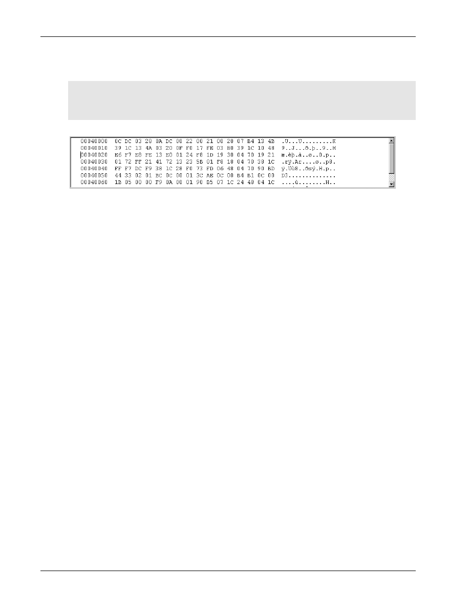
To view the memory viewer, as shown in Figure 4–10, select Memory Viewer from the middle menu.
2
The memory viewer provides peek and poke into the subscriber memory. This display allows you to
3
view and edit memory locations inside the phone at run-time. To edit memory, modify the contents
4
and then press E
NTER
or E
SC
.
5
6
Figure 4–10 Memory viewer
7
8
80-V1241-21 Rev. A
QUALCOMM Proprietary
5-1
5 Logging
Logging is enabled/disabled by pressing A
LT
+L or by selecting Options
→ Logging. To edit the log
1
mask, use the Options
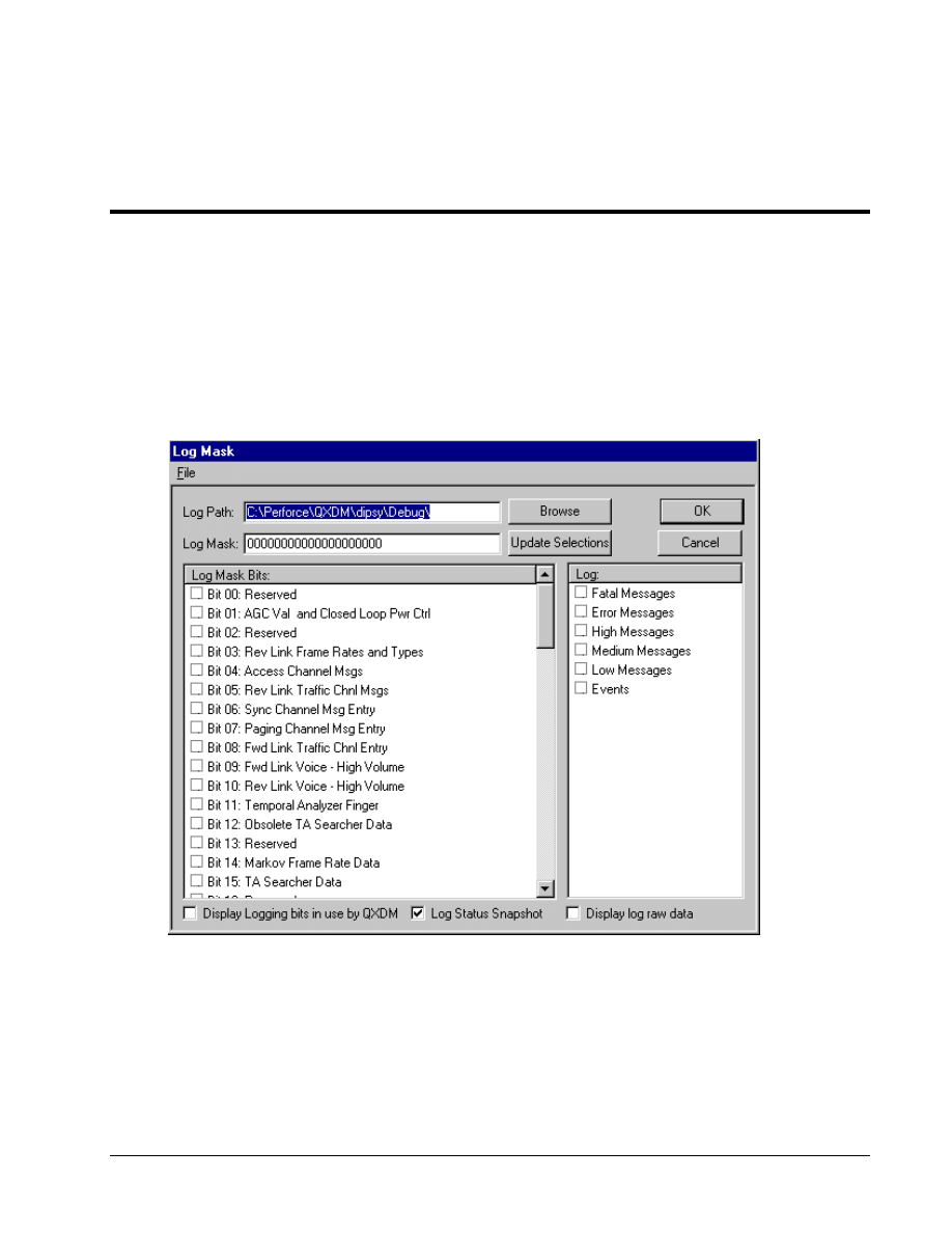
→ Log Mask dialog; you may also display this dialog by pressing F5.
2
Figure 5–1 depicts the dialog.
3
4
Figure 5–1 Log Mask Configuration dialog
5
6

Logging
QXDM Software Users Guide
5-2
QUALCOMM Proprietary
80-V1241-21 Rev. A
If you change the log mask by typing a log mask string in the Log Mask dialog, you must click
1
Update Selections
after entering the new log mask.
2
The number of bits displayed in the Log Mask dialog will vary depending on the number of bits
3
supported by the connected FFA or SURF. To configure the names of the log mask bits, edit the
4
logmask.txt file located in the property\qxdm directory in the QXDM installation directory.
5
Select the Display Logging bits in use by QXDM check box to highlight the log bits that are in use
6
due to display views you may have showing.
7
Select the Log Status Snapshot check box to enable logging of the tool-generated Status snapshot
8
packet.
9
Select the Display log raw data check box to display the contents of log packets to the
10
Messages <F3> screen.
11
If a screen that uses logging data is loaded, such as Status or Temporal Analyzer, the logging bits
12
required by these screens cannot be changed by you. These screens must first be unloaded in order to
13
change these bits. You may still disable logging entirely while these screens are loaded.
14
You can also specify the location on your machine where you want the log files saved. If the log path
15
is empty, the log files will be saved in the current directory by default.
16
17
80-V1241-21 Rev. A
QUALCOMM Proprietary
6-1
6 Properties
QXDM uses properties to access data in the phone. Properties provide a way for the user to describe
1
target data structures to QXDM dynamically.
2
Some properties are defined using a property file. Other properties are defined by the DWARF server
3
(see Chapter 10 for more information) and do not have a corresponding property file. In either case,
4
access to properties is typically performed using HTML scripts. The other approach is to use the
5
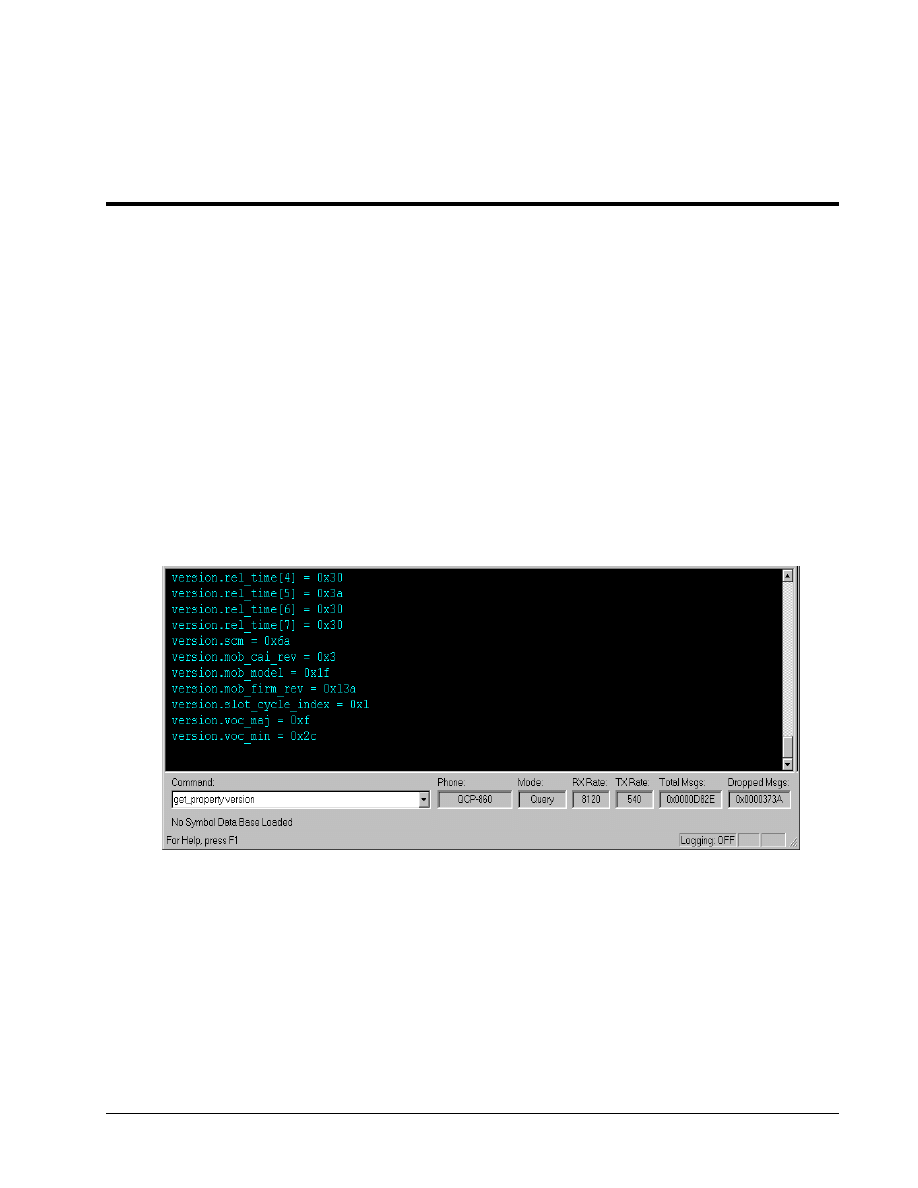
list_properties, get_property, print_property,
and
put_property
commands on
6
QXDM’s command line, as shown in Figure 6–1. Use
get_property
to read data and
7
put_property
to write data to the phone. The
print_property
command displays the property
8
definition that QXDM is using. This is helpful as a lookup for property field names and when
9
debugging user-generated properties.
10
11
Figure 6–1 Command line access to properties
12
13

Properties
QXDM Software Users Guide
6-2
QUALCOMM Proprietary
80-V1241-21 Rev. A
Listing properties
1
The list of current properties or properties matching a given pattern can be displayed using the
2
following syntax:
3
list_properties [part of a property name]
4
[part of a property name]
is optional and will result in a list of all current properties matching
5
the part specified.
6
Reading property data
7
Reading property data is done using the following syntax:
8
get_property
<PropertyName>
9
<PropertyName>
is the name of the property to be read. Typing
get_property
before the
10
property name is optional for all base property names except NV Items.
11
Writing property data
12
Writing property data is done using the following syntax:
13
put_property <PropertyName> <PropertyArguments>
14
<PropertyName>
is the name of the property to be written. Typing
put_property
before the
15
property name is optional for all base property names except NV Items.
<PropertyArguments>
16
refers to all property field values separated by spaces or commas with spaces.
17
Printing property definitions
18
Printing a property definition is done using the following syntax:
19
print_property
<PropertyName>
20
<PropertyName>
is the name of the property to be listed.
21
22

QXDM Software Users Guide
Properties
80-V1241-21 Rev. A
QUALCOMM Proprietary
6-3
6.1 Property definition
1
Properties are defined as shown in Table 6-1. Comments may be added using the # character for
2
properties defined in property files. Anything following a # is assumed to be a comment and is
3
ignored. Each noncomment line of a property file will contain the following information (square
4
brackets indicate optional parameters):
5
Property.Element, Offset, Size [, Description, Data Type, Command/Item
6
enum/Address]
7
Table 6-1 Property file information
8
Item Description
Property
Name of the property
Element
Name of an element within the property
Offset
Offset of the element from the start of the packet
Size
Size in bytes of the element
Description
Description of the element
Data type
One of the following data types: INT, UINT, CHAR, HEX
Command/item enum/address
Command or Item ID for a packet definition or data address
9
6.2 Property packets
10
The following properties are defined as packets. Refer to the CDMA DMSS Serial Data Interface
11
Control Document, 80-V1294-1 X6, specific Application Note documents, or Compatibility Notes for
12
the actual packet descriptions.
13
Diagnostic property packet
14
The element name
cmd_code
is always the first element of any diagnostic property packet. The line
15
containing the element
cmd_code
must also have the actual Command ID of the diagnostic packet
16
as the sixth parameter, as shown in the following example:
17
18
Markov.cmd_code, 0,
1,,, 26
19
The offset of the
cmd_code
is always
0
,
and the size is always
1
.
The sixth parameter is the
20
Command ID (shown as
26
in the Markov example).
21
22

Properties
QXDM Software Users Guide
6-4
QUALCOMM Proprietary
80-V1241-21 Rev. A
Log property packet
1
The element names
length
,
log_code,
and
time_stamp
are always the first three elements of
2
any log property packet. The line containing the element
log_code
must have the actual log code of
3
the log packet as the sixth parameter:
4
5
genta.length, 0,
2
genta.log_code, 2,
2,,, 25
genta.time_stamp, 4,
8
6
The offset of the
log_code
is always
2
,
and the size is always
2
.
The sixth parameter is the Log
7
Code (shown as
25
in the General Temporal Analyzer genta log packet example).
8
NV Item property packet
9
The element name
nv_item
is always the first element and
nv_stat
is always the last element of
10
any NV Item property packet. The line containing the element
nv_item
must have the actual NV
11
Item number of the NV Item packet as the sixth parameter:
12
13
esn.nv_item, 0,
2,,, 0
esn.esn, 2,
4
esn.nv_stat, 6,
2
14
The offset of the
nv_item
is always
0
,
and the size is always
2
. The sixth parameter is the NV
15
Item number (shown as
0
in the
nv_esn
NV item example). The offset of
nv_stat
is based upon
16
the total size of the NV Item. In the
nv_esn
example, the offset is
6
.
The size of
nv_stat
is
17
always
2
.
18
6.3 Absolute address on the phone
19
The
abs_addr
element is always the first element of any absolute address property definition. The
20
line containing the element
abs_addr
must have the actual address of the data as the sixth
21
parameter. If the address is written in hexadecimal, then
0x
must be prepended to the address as
22
shown below:
23
24
MSM5000_DEMOD_RESET.abs_addr, 0,
4,,, 0x3000000
MSM5000_DEMOD_RESET.length, 4,
2
MSM5000_DEMOD_RESET.data, 6,
4
25
26

QXDM Software Users Guide
Properties
80-V1241-21 Rev. A
QUALCOMM Proprietary
6-5
6.4 Properties with arrays
1
The recommended representation of array elements is to specify each array element. For example, an
2
array of two elements, each 4 bytes in size (for example, dword array[2]), is defined as (assume 20
3
bytes of additional elements precede
packet_name.array
):
4
5
packet_name.array, 20,
8
packet_name.array[0], 20,
4
packet_name.array[1], 24,
4
6
If the array is defined this way, you may then access the array elements, from JavaScript, in two
7
ways:
8
9
GetProperty("packet_name.array[0]");
10
GetProperty("packet_name.array[1]");
11
12
or
13
14
GetPropertyEx("packet_name.array", 0, 4);
15
GetPropertyEx("packet_name.array", 4, 4);
16
17
Using the
GetPropertyEx()
method allows easier access to array elements. For example:
18
19
arraySize = GetSize("packet_name.array");
20
elementSize = GetSize("packet_name.array[0]");
21
for (ii = 0; ii < arraySize; ii += elementSize)
22
{
23
data = GetPropertyEx("packet_name.array", ii, elementSize)
24
....
25
}
26
27

Properties
QXDM Software Users Guide
6-6
QUALCOMM Proprietary
80-V1241-21 Rev. A
6.5 Structures in properties
1
All text before the first dot (‘.’) in the name is considered the property name. All text after the first
2
dot in the name is considered the element name. Therefore, nested structures can be represented by a
3
list of elements separated by dots. Consider the following example of a structure embedded within a
4
packet:
5
6
struct structure
7
{
8
word wordItem,
9
byte byteItem,
10
long longItem
11
}
12
(assume 20 bytes of additional elements precede
packet_name.structure
)
13
.....
packet_name.structure.wordItem, 20,
2
packet_name.structure.byteItem, 22,
1
packet_name.structure.longItem, 23,
4
14
With data structures, defining the following would not be useful and is not recommended:
15
16
packet_name.structure, 20, 7
17
18

QXDM Software Users Guide
Properties
80-V1241-21 Rev. A
QUALCOMM Proprietary
6-7
6.6 Property support tools
1
Two tools are provided with QXDM to simplify the task of building property files and HTML scripts.
2
Perl from ActiveState, version 5.005_03 or newer, and Microsoft C++ 6.0 or newer are required to
3
run the tools. They are located in the qxdm\property\user directory where QXDM is installed.
4
It is important to ensure that both the Microsoft VC++ 6.0 compiler and Perl run from the MS-DOS
5
command shell. It should be possible to run these tools and obtain results similar (may differ slightly
6
on your machine) to the following:
7
8
C:\> cl
9
Microsoft (R) 32-bit C/C++ Optimizing Compiler Version 12.00.8168 for 80x86
10
Copyright (C) Microsoft Corp 1984-1998. All rights reserved.
11
usage: cl [ option... ] filename... [ /link linkoption... ]
12
13
C:\> perl -v
14
This is perl, v5.6.1 built for MSWin32-x86-multi-thread
15
(with 1 registered patch, see perl -V for more detail)
16
17
C:\Program Files\Qualcomm\QXDM\property\user>perl makeProp.pl -help
18
MakeProp
19
Make Property File
20
Creates .prop file from C header file.
21
Options: -I=<path> Search include paths
22
...
23
24
If the results are not similar, makeProp and makeHTML will fail.
25
26

Properties
QXDM Software Users Guide
6-8
QUALCOMM Proprietary
80-V1241-21 Rev. A
6.6.1 makeProp tool
1
makeProp
creates a property file (.prop) from a C header file containing typedef structs.
2
3
Syntax: makeProp [options] header
4
5
Options: -I=<path> Search include paths
6
-nvitems Build NV item property file from the DMSS nv.h.
7
-cmd=<Command Code> Use <Command Code> value
8
-item=<Item Name> Use <Item Name>
9
-types=<type(s)> Get list of types from a C header file. Enclose
10
types in double quotes if more than one type or
11
use a response file (preceded with @).
12
-diagPkt Build diag packet property file.
13
14
Examples: makeProp.pl -nv nvTypes.h -I=C:\dmss
15
makeProp.pl -cmd=26 -item=markov markovStruct.h
16
makeProp.pl diagpkt.h -diagpkt -types=diag_password_req_type
17
18
makeProp.pl is included with QXDM to aid in generating properties from C typedef structs, but is
19
very limited due to the text processing nature of the tool.
20
Using a new property
21
To enable QXDM to use a new property file, copy it to the QXDM\Property\qxdm folder where
22
QXDM was installed and restart QXDM.
23
6.6.2 makeHTML tool
24
makeHTML
creates an HTML file from a property file that was created by
makeProp
.
25
26
Syntax: makeHTML [options] property_file ...
27
28
Options: -h Display this message.
29
-f=<html file> Write all HTML output to <html file>. Default is
30
to write a separate HTML file for each property
31
contained in the input file.
32
33
Example: makeHTML.pl my_data.prop -f=my_data.html
34
35
Using a new HTML display
36
To enable QXDM to use a new HTML display, copy it to the QXDM\HTML folder where QXDM
37
was installed and restart QXDM.
38

80-V1241-21 Rev. A
QUALCOMM Proprietary
7-1
7 Events
Events are properties that have additional features described in this chapter.
1
Events are enabled or disabled by pressing A
LT
+E or by selecting Options
→Event Reporting. When
2
enabled, events are displayed in the Messages <F3> window or in other displays containing events.
3
Note that event reporting is automatically enabled when you bring up any event displays even when
4
the Event Reporting option is turned off. Event reporting is automatically disabled when there are no
5
event displays and the Event Reporting option is turned off.
6
7.1 Event information
7
All event information such as event name, event payload parsing format, event/category relationship,
8
and so on, is stored in the QXDM Property database and can be modified using the QXDM Property
9
Editor. See Chapter 8 for further details.
10
7.2 Event display
11
There are two types of event-based display: scrolling display and table display.
12
13
Events
QXDM Software Users Guide
7-2
QUALCOMM Proprietary
80-V1241-21 Rev. A
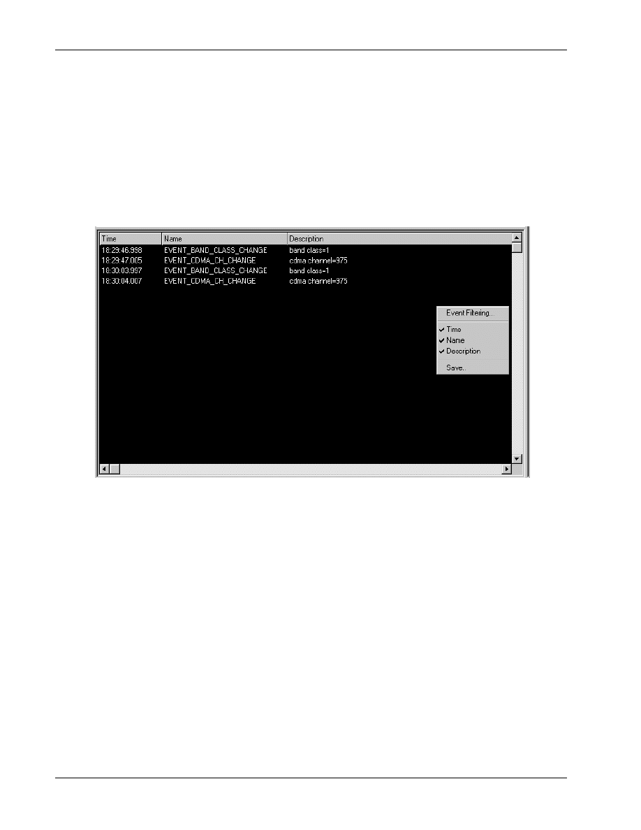
7.2.1 Scrolling display
1
The scrolling display is similar to the Messages <F3> screen in which the events are scrolled down
2
and sorted by the timestamp. You can right-click the display to bring up the Event Options menu.
3
From this options menu the display can be configured and the autoscrolling feature can be paused.
4
See Section 7.3 for further details on configuring the display.
5
You can view up to three event displays simultaneously by using all three splitter windows.
6
7
Figure 7–1 Scrolling event display
8
9
QXDM Software Users Guide
Events
80-V1241-21 Rev. A
QUALCOMM Proprietary
7-3
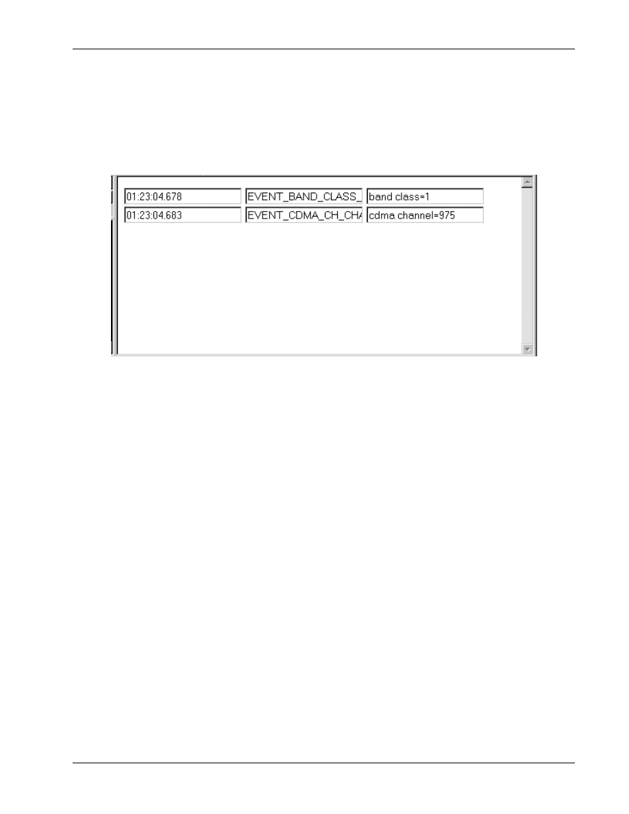
7.2.2 Table display
1
This type of display shows event information in a tabular format. The event data is refreshed when
2
new events arrive.
3
4
Figure 7–2 Table event display
5
The display is HTML-based. The example below shows how to write a table event display such as the
6
7
8
<!NAME="HDR State Status" WIDTH=450 HEIGHT=290>
9
<HTML>
10
<HEAD>
11
<TITLE> HDR State Status</TITLE>
12
<STYLE TYPE="text/css">
13
DIV {font-size:11pt}
14
SPAN {font-size:11pt}
15
.expandable {color:black; cursor:hand}
16
.expanded {color:blue; margin-left:10pt}
17
.collapsed {display:none}
18
</STYLE>
19
</HEAD>
20
21
<SCRIPT LANGUAGE="JavaScript">
22
HTML_PAGE_NAME = " HDR State Status";
23
24

Events
QXDM Software Users Guide
7-4
QUALCOMM Proprietary
80-V1241-21 Rev. A
1
// Check whether IE4 or later.
2
var MS = navigator.appVersion.indexOf("MSIE");
3
window.isIE4 = (MS > 0) &&
4
(parseInt(navigator.appVersion.substring(MS + 5, MS + 6)) >= 4);
5
</SCRIPT>
6
<SCRIPT LANGUAGE="JavaScript" SRC="IDispatch.js"></SCRIPT>
7
8
<BODY>
9
<INPUT TYPE="text" ID=EVENT_BAND_CLASS_CHANGE NAME="Timestamp" VALUE="timestame">
10
<INPUT TYPE="text" ID=EVENT_BAND_CLASS_CHANGE NAME="Name" VALUE="name">
11
<INPUT TYPE="text" ID=EVENT_BAND_CLASS_CHANGE NAME="Description" VALUE="description">
12
<BR>
13
<INPUT TYPE="text" ID=EVENT_CDMA_CH_CHANGE NAME="Timestamp" VALUE="timestame">
14
<INPUT TYPE="text" ID=EVENT_CDMA_CH_CHANGE NAME="Name" VALUE="name">
15
<INPUT TYPE="text" ID=EVENT_CDMA_CH_CHANGE NAME="Description" VALUE="description">
16
<BR>
17
</BODY>
18
</HTML>
19
20
The code in the HTML body describes how we specify which events are to be filtered and which
21
columns are to be displayed.
22
23
QXDM Software Users Guide
Events
80-V1241-21 Rev. A
QUALCOMM Proprietary
7-5
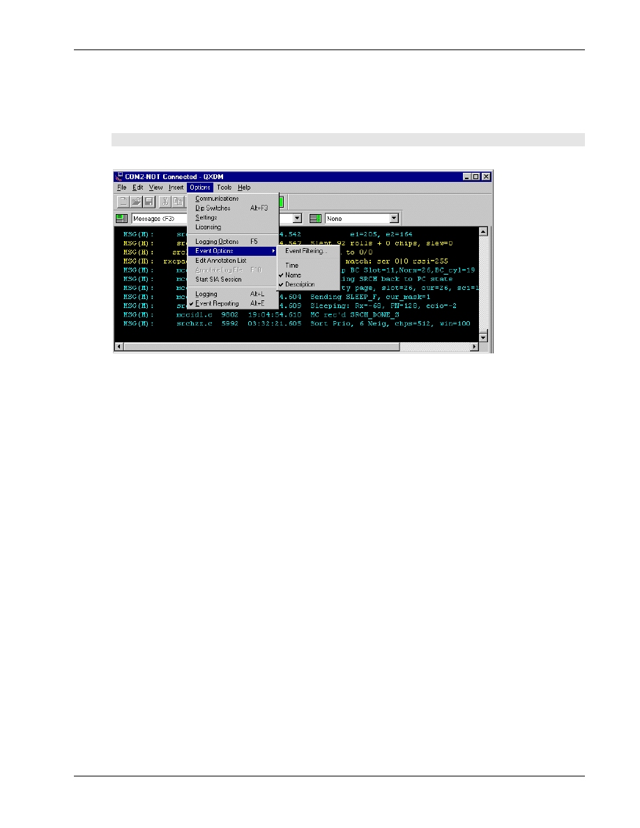
7.3 Event options
1
This feature allows users to configure the scrolling event display.
2
3
Figure 7–3 Options
→ Event Options
4
Select Options
→ Event Options from the QXDM menu.
5
■
Event Filtering – filters the events and/or event categories you want to see in the displays. Select
6
this to bring up the Event Filtering Dialog. See Section 6.3 for further details
7
■
Time – displays/hides the Timestamp column
8
■
Name – displays/hides the Name column
9
■
Description – displays/hides the Description column
10
The Event Options setting that you select from the main menu has a global effect. This means that the
11
configuration is applied to all the event displays that are subsequently brought up. However, it will
12
not affect the ones currently displayed.
13
To change the configuration of a particular event display, right-click the display to bring up the
14
options menu. The configuration change is only applied locally to this display and does not affect
15
other event displays.
16
17
Events
QXDM Software Users Guide
7-6
QUALCOMM Proprietary
80-V1241-21 Rev. A
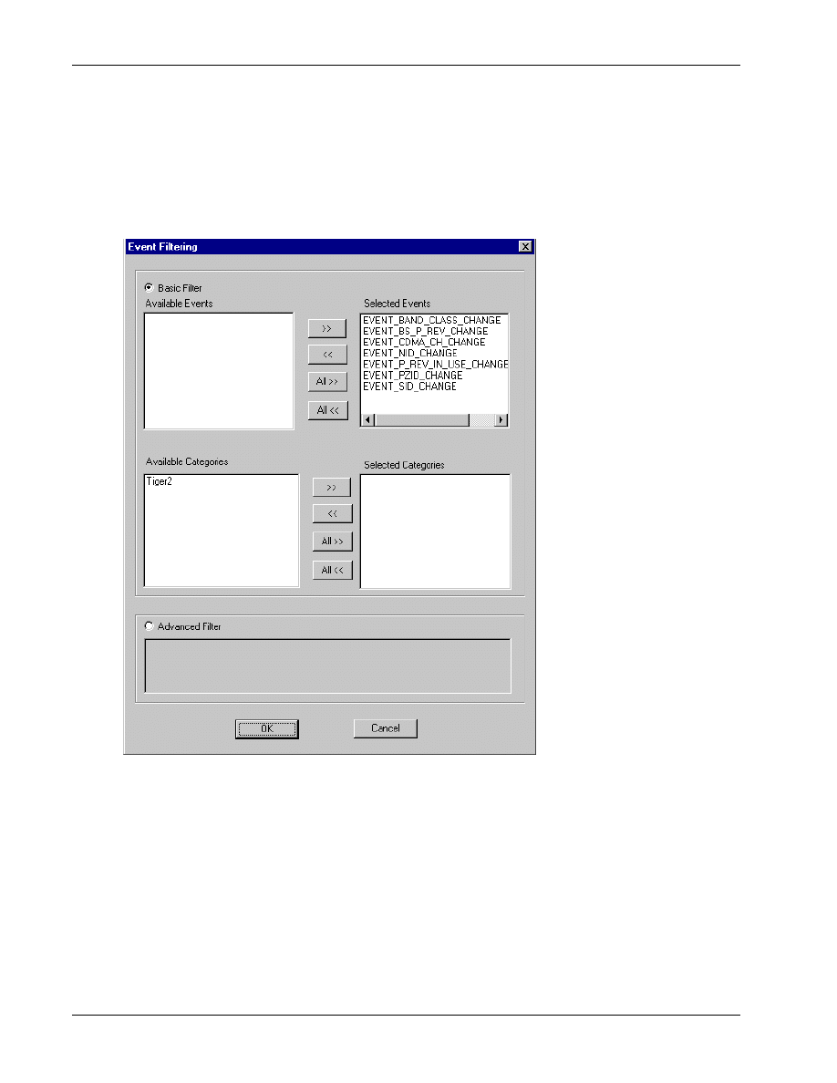
7.4 Event filtering
1
Event Filtering allows QXDM users to select which events and event categories they want to see in
2
the display. This is illustrated in Figure 7–4.
3
4
Figure 7–4 Event filtering
5
6

QXDM Software Users Guide
Events
80-V1241-21 Rev. A
QUALCOMM Proprietary
7-7
7.4.1 Basic event filtering
1
To use the basic filtering, select the Basic Filter option in the Event Filtering dialog screen.
2
Use the buttons to select the events and categories you want to see in the event displays. Category is
3
used to conveniently group similar events together, so that you can filter a group of events instead of
4
each event individually. The event/category relationship is defined in the QXDM database, and can
5
be modified using the QXDM Property Editor. See Chapter 8 for further details.
6
7.4.2 Advanced event filtering
7
This feature allows users to perform more complex filtering by issuing an SQL query directly to the
8
database.
9
To use the advanced filtering, select the Advanced Filter option in the Event Filtering dialog screen,
10
and then enter the SQL-like query. The query should follow the SQL syntax as in the WHERE clause.
11
Consult appropriate documents for SQL syntax.
12
Note that:
13
■
Can refer to an event by ID or by name
14
■
Have to use double quotes for a string, such as an event name or category
15
Here are some examples using Tiger 2 events to illustrate how to use this feature:
16
1. To select event EVENT_BAND_CLASS_CHANGE, enter ID=256
17
Or you can enter:
18
Name="EVENT_BAND_CLASS_CHANGE"
19
2. To select event EVENT_BAND_CLASS_CHANGE and event EVENT_CDMA_CH_CHANGE,
20
enter ID=256 or ID=257
21
Or you can enter:
22
ID=256 OR Name="EVENT_CDMA_CH_CHANGE"
23
3. To select all events in Tiger2 category, enter CategoryName="Tiger2"
24
4. To select all events in Tiger2 category, except event EVENT_BAND_CLASS_CHANGE, enter:
25
CategoryName="Tiger2" AND NOT Name="EVENT_BAND_CLASS_CHANGE"
26
Or you can enter:
27
CategoryName="Tiger2" AND NOT ID=256
28
5. To select all events in Tiger2 category, except those in Category1, enter CategoryName="Tiger2"
29
AND NOT CategoryName="Category1"
30

Events
QXDM Software Users Guide
7-8
QUALCOMM Proprietary
80-V1241-21 Rev. A
7.5 Custom event display
1
This feature provides QXDM users the flexibility to create their own customized event displays and
2
save them in text-based XML format. XML is a markup language concerned with the description and
3
structuring of data, and is fast becoming the language of choice for data storage.
4
The following is an example of an event display in XML format is:
5
<Display>
6
<Name>HDR
State</Name>
7
<Column>Timestamp</Column>
8
<Column>Name</Column>
9
<Event>EVENT_BAND_CLASS_CHANGE</Event>
10
<Event>EVENT_BS_P_REV_CHANGE</Event>
11
<Event>EVENT_CDMA_CH_CHANGE</Event>
12
<Event>EVENT_NID_CHANGE</Event>
13
<Event>EVENT_P_REV_IN_USE_CHANGE</Event>
14
<Event>EVENT_PZID_CHANGE</Event>
15
<Event>EVENT_SID_CHANGE</Event>
16
<Category>Tiger2</Event>
17
<BasicFilter>0</BasicFilter>
18
<Query>ID=101 OR Name="EVENT_1"</Query>
19
</Display>
20
21
There are two ways to create a custom event display:
22
1. Use the QXDM GUI. Bring up a generic Events display from the QXDM menu. Right-click the
23
display to configure the filtering and select the columns to be displayed. Select Save and enter a
24
name to save the selected configuration into a new custom event display. Note that the name has
25
to be unique or you would get an error. The new display is dynamically loaded into QXDM, so
26
you can select it from the QXDM menu.
27
2. Modify the XML file directly. Make sure the change is syntactically correct by running the XML
28
file through an XML parser. Microsoft Internet Explorer 5 has a built-in XML parser, so just
29
make sure you can open the file successfully with IE5. QXDM also logs parsing errors if there are
30
any when it loads the XML file. Note that the changes are not dynamically loaded to QXDM, so
31
you have to restart QXDM.
32
There are two XML files:
33
❒
- \property\QXDM\Displays.xml – This is the official XML file to be shipped with every
34
QXDM release, and is overwritten during the installation.
35
❒
- \property\user\UserDisplays.xml – This is the user XML file; it will not be overwritten
36
during the installation. The custom displays you create via the QXDM GUI are stored in this
37
file. If you want your custom displays to be official and shipped with the QXDM release, you
38
must submit your displays to the Tools team so that they can be included in the official XML
39
file.
40
41

80-V1241-21 Rev. A
QUALCOMM Proprietary
8-1
8 Property Editor
QXDM stores Event and Property definitions in a database (*.qdb) format. QXDM uses two of these
1
database files, the QXDM built-in database and the user database. The QXDM Property Editor allows
2
you to edit the contents of the user database. The Property Editor can be accessed from Start
→
3
Programs
→ QXDM → QXDM Property Editor.
4
5
NOTE
The Property Editor treats Events as a type of Property. So in this chapter, the term “Property”
includes Events.
6
8.1 Built-in Property database
7
The QXDM Built-in Property database is found in the Property\QXDM folder in your QXDM
8
installation. This database contains officially published Properties that are distributed to all QXDM
9
users. The contents of this database changes between releases of QXDM. QUALCOMM recommends
10
that you do not modify the contents of this database. The Property Editor allows you to browse the
11
contents of this database but not modify its contents.
12
The Properties and Categories from the Built-in database are displayed next to dark, grayed icons to
13
indicate that these are read-only entities.
14
8.2 User Property database
15
The User Property database is found in the Property\User folder in your QXDM installation. This
16
database is empty in a new installation. This database will contain the Properties that are created by
17
you locally. The Property Editor automatically stores user-defined Properties in this database. It
18
allows you to modify the contents of this database.
19
The Properties and Categories from the User database are displayed next to light, nongrayed icons to
20
indicate that these can be modified or deleted.
21
Property Editor
QXDM Software Users Guide
8-2
QUALCOMM Proprietary
80-V1241-21 Rev. A
8.3 Property Editor User Interface
1
The Property Editor application has an Explorer-style splitter window user interface, as shown in
2
3
4
Figure 8–1 Property Editor window
5
8.3.1 Splitter Window Overview of the Property Editor
6
The left panel of the application window displays the Properties and Categories in a tree format. Each
7
Property type is displayed as a folder in the tree. The tree also has a special folder containing all the
8
Categories in the database.
9
The individual properties are listed under the appropriately named folder. Selecting an individual
10
Property or Category in the left panel displays more information about the selected item in the right
11
panel of the splitter window. The right panel of the splitter window is empty if a folder or the
12
database root node is selected in the left panel.
13
QXDM Software Users Guide
Property Editor
80-V1241-21 Rev. A
QUALCOMM Proprietary
8-3
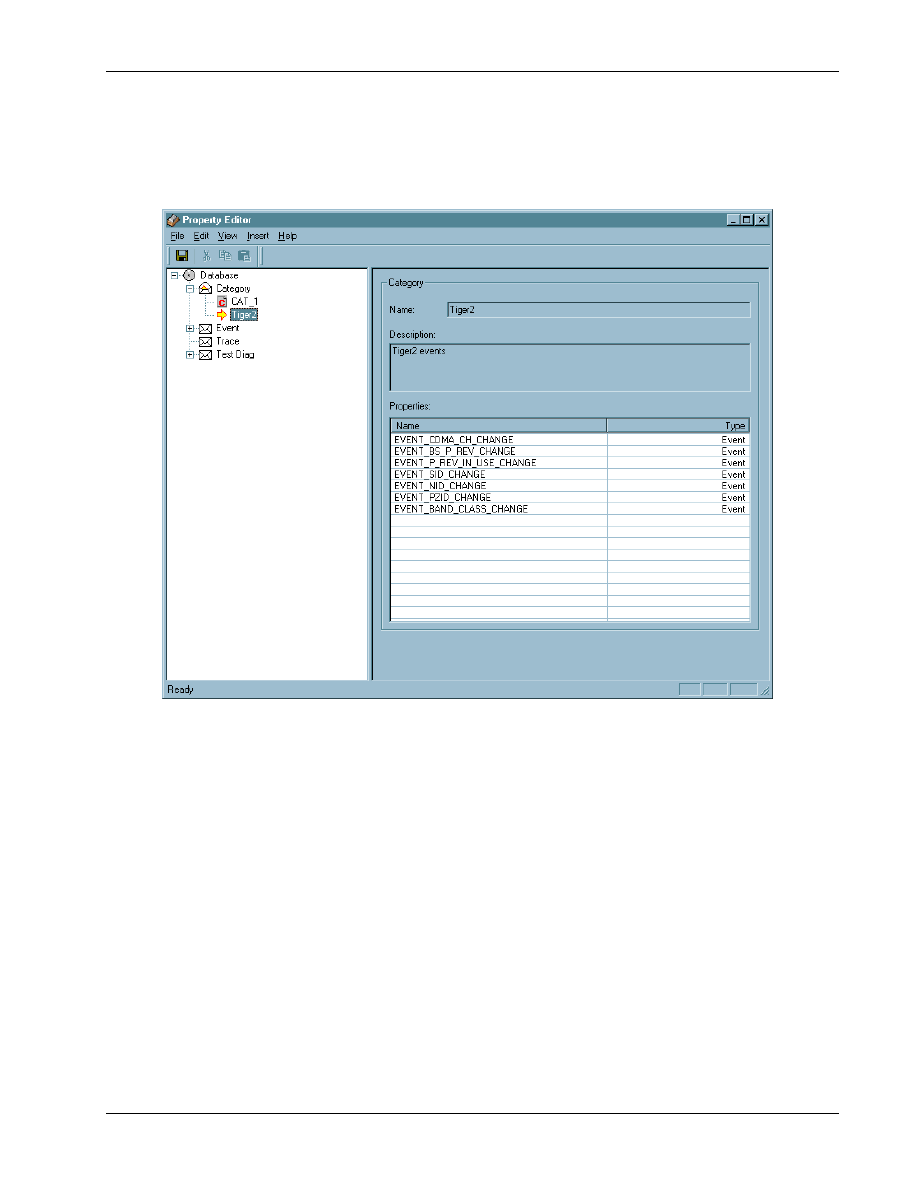
8.3.2 Category Display of the Property Editor
1
Figure 8–2 depicts the Category display splitter window.
2
3
Figure 8–2 Category display
4
The Category display on the right panel shows the name of the Category, its description, and a table
5
containing all the Properties that belong to the specified Category, along with their types. If Category
6
is user-defined, the Description field can be edited. The Properties table is read-only. To change the
7
Category assignment for an individual Property, use the display for that Property.
8
Property Editor
QXDM Software Users Guide
8-4
QUALCOMM Proprietary
80-V1241-21 Rev. A
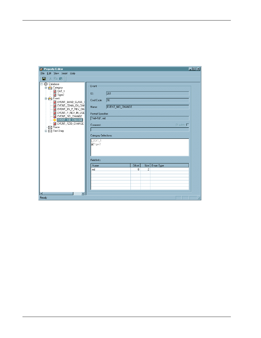
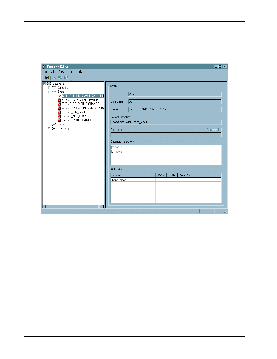
8.3.3 Property Display of the Property Editor
1
Figure 8–3 depicts the Property display splitter window.
2
3
Figure 8–3 Property display
4
The Property display on the right panel shows the type of the Property, its ID, command code, name,
5
format specifier string for QXDM displays, and a table containing the Property Field organization for
6
the given Property. The display also contains a check list for the Categories with the relevant
7
Categories selected. A check box titled Obsolete indicates if the given Property is obsolete. There is
8
also a Comment edit field.
9
For user-defined Properties, you are allowed to modify the Category Selections, Format Specifier,
10
and the Comment fields. The Property Editor also provides a facility to edit the Field assignments for
11
the Property.
12
13
QXDM Software Users Guide
Property Editor
80-V1241-21 Rev. A
QUALCOMM Proprietary
8-5
8.4 Working with properties
1
The Property Editor does not allow you to modify or delete built-in Properties. The following sections
2
describe the steps to work with user-defined Properties.
3
8.4.1 Inserting a new property
4
To insert a new property:
5
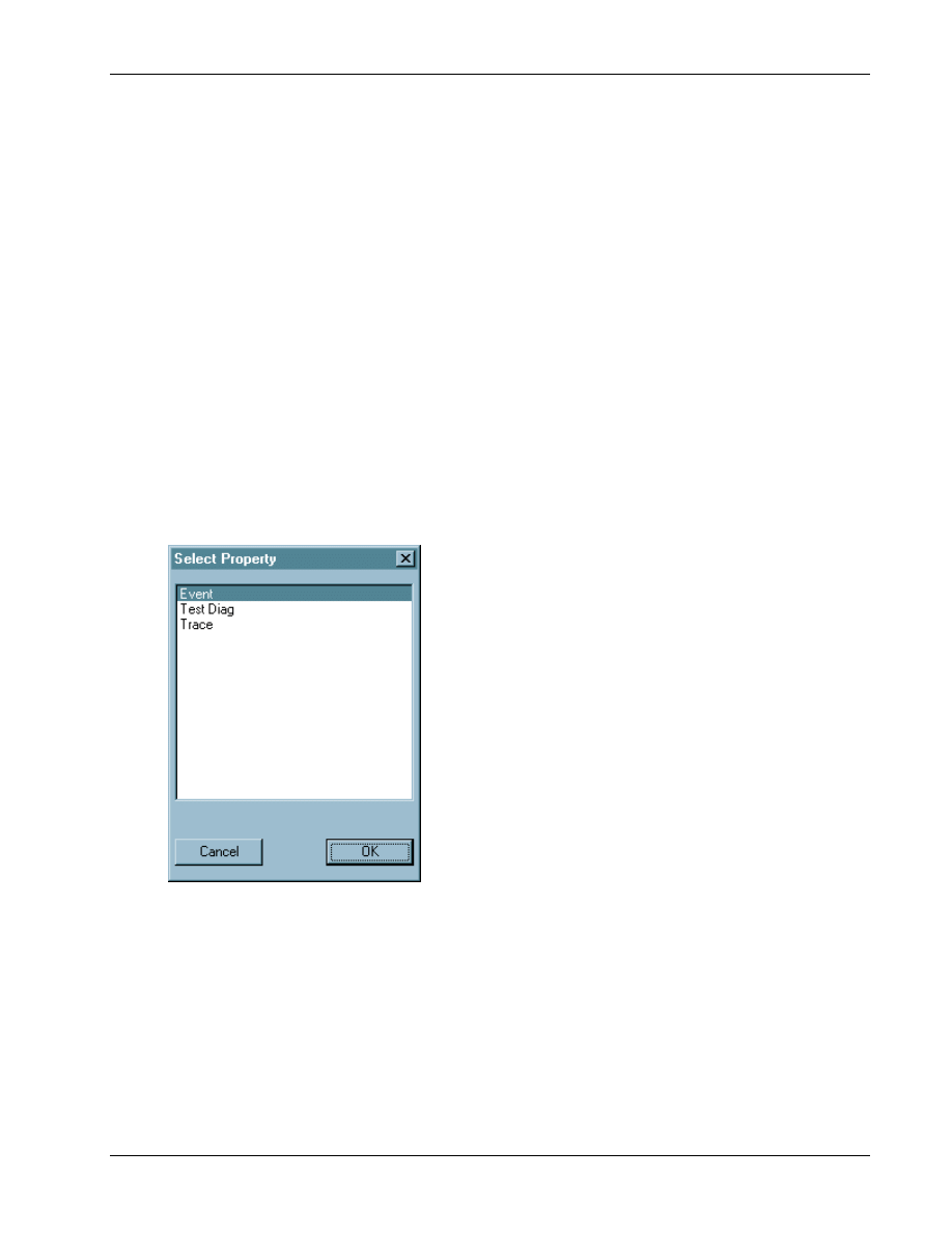
1. Select
Insert
→Property or press F3.
6
This brings up the select Property dialog, as shown in Figure 8–4.
7
2. Select the type of the new Property to be inserted and click
OK
.
8
A new Property is created with a default name under the folder that corresponds to the selected
9
Property type.
10
3. Rename the new Property as desired.
11
12
Figure 8–4 Select Property dialog
13
14

Property Editor
QXDM Software Users Guide
8-6
QUALCOMM Proprietary
80-V1241-21 Rev. A
8.4.2 Renaming a property
1
To rename a property:
2
1. Select the Property to be renamed.
3
2. Select
Edit
→Rename or press C
TRL
+
R
.
4
This makes the selected left-panel node editable (see Figure 8–3 left panel).
5
3. Type in the new name for the Property.
6
4. Press
E
NTER
.
7
8.4.3 Deleting a property
8
To delete a property:
9
1. Select the Property to be deleted.
10
2. Select
Edit
→Delete or press D
ELETE
.
11
This removes the selected left-panel node (see Figure 8–3 left panel).
12
8.4.4 Modifying category selections
13
In the Category Selections check list (shown in Figure 8–3 right panel), check the desired Categories
14
and uncheck the others.
15
8.4.5 Modifying property field structure
16
Double-click the Field Info table (shown in Figure 8–3 right panel) to invoke the Field Edit dialog.
17
See Section 8.6 for information on working with Property fields.
18
8.5 Working with categories
19
The Property Editor does not allow you to modify or delete built-in Categories. The following
20
sections describe the steps to work with user-defined Categories.
21
8.5.1 Adding a new category
22
To add a new category:
23
1. Select
Insert
→Category or press F2.
24
A new Category is created with a default name under the Category folder.
25
2. Rename the new Category as desired.
26
QXDM Software Users Guide
Property Editor
80-V1241-21 Rev. A
QUALCOMM Proprietary
8-7
8.5.2 Renaming a category
1
To rename a category:
2
1. Select the Category to be renamed.
3
2. Select
Edit
→Rename or press C
TRL
+
R
.
4
This makes the selected left-panel node editable (see Figure 8–2 left panel).
5
3. Type in the new name for the Category.
6
4. Press
E
NTER
.
7
8.5.3 Deleting a category
8
To delete a category:
9
1. Select the Category to be deleted.
10
2. Select
Edit
→Delete or press D
ELETE
.
11
This removes the selected left-panel node (see Figure 8–2 left panel).
12
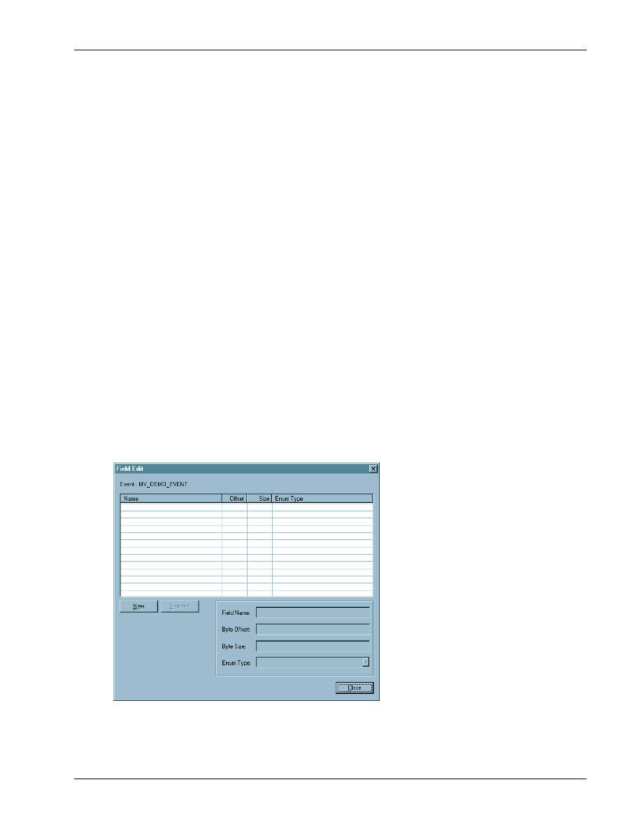
8.6 Working with property fields
13
Double-clicking the Property Field table of a user-defined Property invokes the Field Edit dialog, as
14
15
16
Figure 8–5 Field Edit dialog
17
The Field Edit dialog displays the type and name of the Property being edited. It also contains a table
18
similar to the Field Info table in the right panel of the Property display (shown in Figure 8–3).
19

Property Editor
QXDM Software Users Guide
8-8
QUALCOMM Proprietary
80-V1241-21 Rev. A
8.6.1 Adding a new property field
1
To add a new property field:
2
1. Click
New
on the Field Edit dialog.
3
This inserts a new Property Field with a default name and field values.
4
2. Change the individual values as described in Sections 8.6.2 and 8.6.3 below.
5
8.6.2 Modifying property field contents
6
To modify property field contents:
7
1. Select the Property Field to be modified.
8
The contents of the selected Property Field are displayed in the Edit Fields at the bottom of the
9
dialog.
10
2. Modify the values as desired.
11
This propagates the change to the display table.
12
8.6.3 Deleting a property field
13
To delete a property field:
14
1. Select the Property Field to be deleted.
15
2. Click
Remove
on the Field Edit dialog.
16
8.7 Saving the database
17
Modifications from the Property Editor are not committed to the database files automatically. The
18
changes have to be saved to the database when required. To save the contents, select File
→Save. The
19
changes made are saved in the User Property database. The QXDM built-in database is left
20
unchanged.
21
If you try to exit the Property Editor application without saving the changes, the application reminds
22
you about the changes and confirms if you want to discard them.
23
24
QXDM Software Users Guide
Property Editor
80-V1241-21 Rev. A
QUALCOMM Proprietary
8-9
8.8 Conflicts
1
Due to the periodic updates to the QXDM built-in database, conflicts may appear in the Property
2
database. A conflict occurs when a new built-in database Property has the same ID or name as an
3
existing user database Property. This happens because Property IDs are sequentially assigned by the
4
Property Editor and the official Property publication mechanism.
5
It is important to check for conflicts each time a new version of QXDM is installed. Conflicts occur
6
only if there are user-defined contents in the database. Use the following ways to verify if there are
7
conflicts in the database:
8
■
In QXDM, most Event or Property displays warn you of conflicts in the database.
9
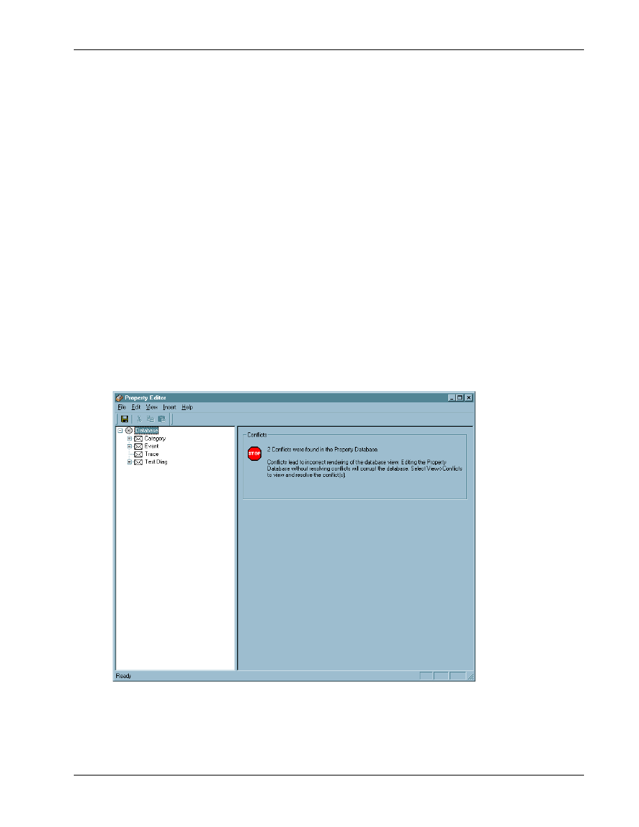
■
Open Property Editor. The opening screen displays a conflict warning message, as shown in
10
11
12
CAUTION
All existing conflicts must be resolved before making any changes to the databases. Failure to do so
will lead to an inconsistent state in the databases. This affects the QXDM displays that depend on
the Property database. These displays may be erroneous or may even cause QXDM to hang or crash.
13
14
Figure 8–6 Property Editor conflict warning
15
Property Editor
QXDM Software Users Guide
8-10
QUALCOMM Proprietary
80-V1241-21 Rev. A
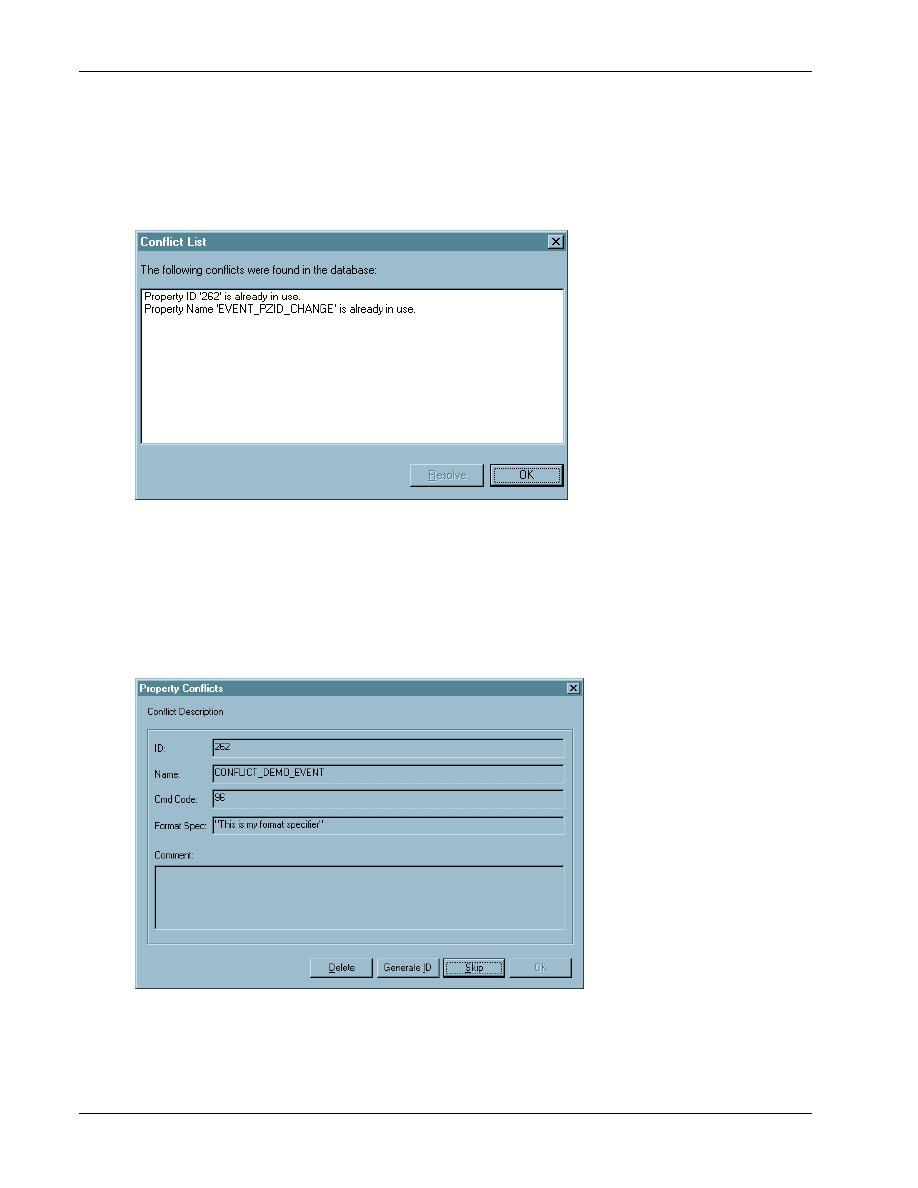
8.8.1 Resolving conflicts
1
The Property Editor provides an extensive auto resolution feature for conflicts. To resolve conflicts,
2
select View
→Conflicts or press F5. This invokes the Conflict List dialog, as shown in Figure 8–7.
3
4
Figure 8–7 Conflict List dialog
5
The conflicts in the Conflict List are selectable. Select each conflict in this list and click
Resolve
.
6
This brings up the Conflict Resolution dialog.
7
If the conflict is between the IDs of two Properties, the Resolution dialog allows you to auto generate
8
a nonconflicting ID or delete the conflicting user-defined Property, as shown in Figure 8–8.
9
10
Figure 8–8 Resolving conflicting property IDs
11
QXDM Software Users Guide
Property Editor
80-V1241-21 Rev. A
QUALCOMM Proprietary
8-11
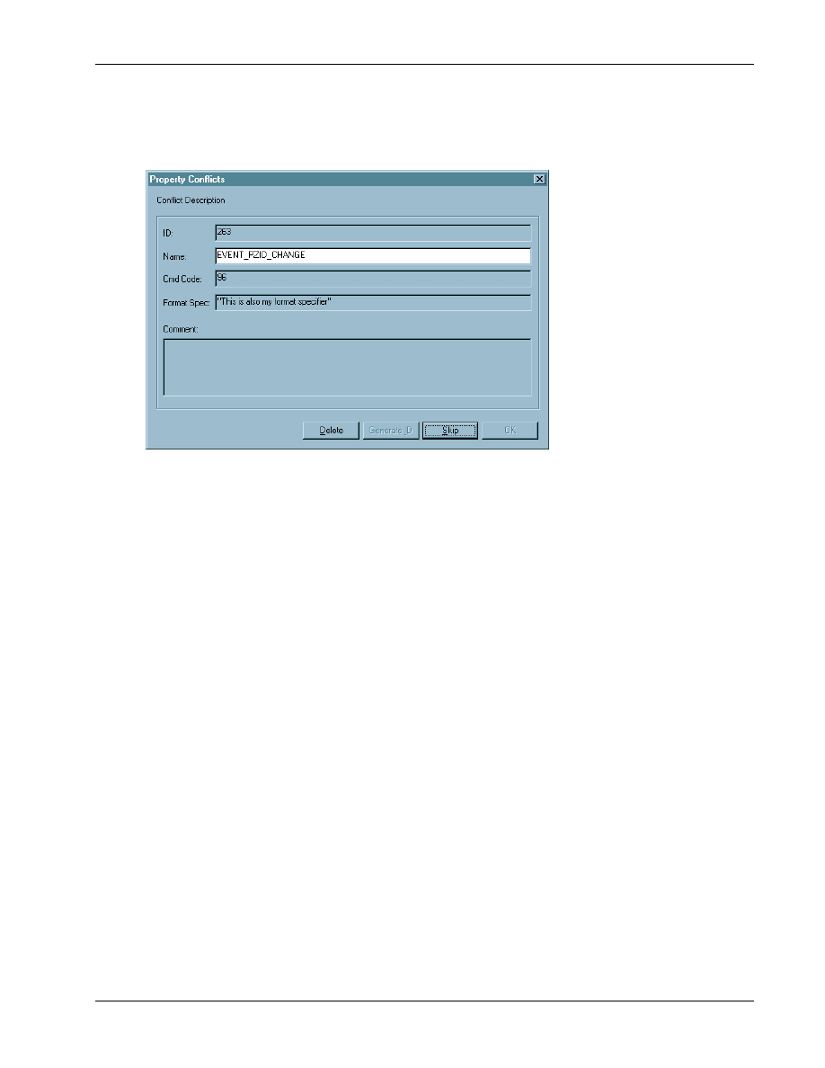
If the conflict is between the names of two Properties, the Resolution dialog allows you to rename the
1
user-defined Property or delete it, as shown in Figure 8–9.
2
3
Figure 8–9 Resolving conflicting property names
4
5

Property Editor
QXDM Software Users Guide
8-12
QUALCOMM Proprietary
80-V1241-21 Rev. A
1

80-V1241-21 Rev. A
QUALCOMM Proprietary
9-1
9 Methods
Methods are functions on the subscriber that are exported and available to QXDM. Currently, all
1
functions are exported as methods. Methods are defined by the DWARF server (see Chapter 10 for
2
more information). QXDM can execute any method on the subscriber as a regular script command.
3
This feature allows you to rapidly add new script commands to QXDM without having to add new
4
diag packets and to modify the script parser.
5
To call the method, you must enter the method name and the parameters in the command window.
6
For example, to call function
foo(int x, long y)
on the subscriber, enter
@foo(1, 2)
. The
7
special character @ preceding the method name is to tell QXDM that it is a method instead of a
8
regular script command. The return value of the method is displayed on the Command Output screen.
9
10
NOTE
The current release of QXDM does not support methods whose parameters are pointers to structures.
11
12

Methods
QXDM Software Users Guide
9-2
QUALCOMM Proprietary
80-V1241-21 Rev. A
1

80-V1241-21 Rev. A
QUALCOMM Proprietary
10-1
10 DWARF Server
The DWARF server is the back-end that enables the Property and Method access features of QXDM.
1
It is a QXDM component that extracts DWARF2 debugging information entries from the executable
2
and linking format (ELF) file associated with a specific software build and services queries on this
3
DWARF2 database via a COM/DCOM interface. QXDM can retrieve DWARF2 debugging
4
information entries on the local machine or on a remote machine running the QXDM server
5
installation.
6
With the help of the DWARF server, QXDM allows you to access global data in the software build as
7
Properties and global functions as Methods. Addressing and type information for the Properties and
8
Methods is retrieved from the DWARF database maintained by the DWARF server.
9
10
NOTE
Properties defined in .prop files do not require the DWARF server to function.
11
10.1 Installation
12
The DWARF database feature requires two server components, Build ID server and DWARF server.
13
As Section 2.2 explains, the server components are installed in the users’ machines to act as the local
14
servers. A separate installer for the Server-Only configuration is available to establish remote servers.
15
In this installation scheme, a QXDM client has access to both local software builds and remote builds.
16

DWARF Server
QXDM Software Users Guide
10-2
QUALCOMM Proprietary
80-V1241-21 Rev. A
10.2 Build process
1
Modifications have been made to the build makefile to generate and register a globally unique
2
identifier for the build. If you have an older version of the makefile, the set of rules for generating the
3
image file must be replaced with the following:
4
5
@echo ------------------------------------------------------------------
6
@echo Generating a GUID for the build
7
@perl diag_guid_gen.pl
8
$(CC) $(CFLAGS) $(DMSS_CFLAGS) $(MSG_FILE) -o $(TARGET)\diag_guid.o
9
diag_guid.c
10
@echo ------------------------------------------------------------------
11
@echo Generating DIAG tables
12
@perl diag_table_gen.pl
13
$(CC) $(CFLAGS) $(DMSS_CFLAGS) $(MSG_FILE) -o $(TARGET)\diag_table.o
14
diag_table.c
15
@echo ------------------------------------------------------------------
16
@echo TARGET $@
17
$(LD) -$(EXETYPE) $(LFLAGS) $(OBJ_CMD) $@ $(LIBS) -VIA << -VIA <<
18
$(OBJECTS)
19
<<
20
$(TARGET)\diag_guid.o $(TARGET)\diag_table.o
21
<<
22
@echo Registering build GUID
23
@perl register_guid.pl $(TARGET).$(EXETYPE)
24
25
In order for a build to support properties and other diagnostic extensions,
FEATURE_DIAG_QCT_EXT
26
must be enabled. For method calling support,
FEATURE_DIAG_RPC
must be enabled.
27
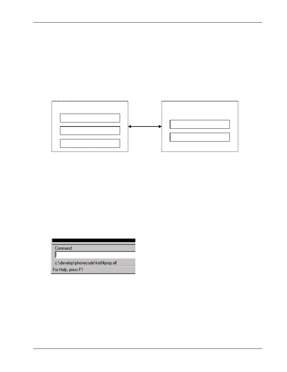
During the build process, the Build ID is compiled into the output ELF file, and an entry that maps
28
the ID to the full pathname of the ELF file is made in the registry. When QXDM initiates
29
communication with a phone or a SURF, it asks for the Build ID before attempting any operation
30
involving properties. The ID is passed to the build server, which locates the matching ELF file by a
31
registry lookup. Operations involving properties are suspended until the ELF file is located and
32
relevant information is loaded from it.
33
If an ELF file is moved from the build directory, it needs to be registered in order for QXDM to find
34
it. To register an ELF file, type
reg_elf.pl <ELF filename>
in an MS-DOS shell.
35
QXDM Software Users Guide
DWARF Server
80-V1241-21 Rev. A
QUALCOMM Proprietary
10-3
10.3 Access process
1
To access Properties and Methods, QXDM needs the ELF file that is output by the software build
2
process. The ELF file is associated with the software build using a unique Build ID. The Build ID is
3
created during the modified Build Process described in the previous section. Also, the Build ID is
4
registered with the QXDM Build Server component on the machine on which the build is performed.
5
Figure 10–1 depicts the access process.
6
DCOM
Local Machine
QXDM Client
Build Server (Local)
DWARF Server (Local)
Remote Machine
Build Server (Local)
DWARF Server (Local)
7
Figure 10–1 Access process
8
The QXDM client (GUI) looks for the Build ID when a SURF/phone is connected. If a Build ID is
9
found in the SURF/phone, QXDM queries the Build server component on the local machine for the
10
ELF file corresponding to the Build ID. If the Build ID is not found in the local machine, QXDM
11
queries the Build server components in a known set of remote machines. This list of remote machines
12
is user-configurable. The configuration process is explained in the following section.
13
If the Build ID was properly registered in either the local machine or one of the remote machines,
14
QXDM invokes the DWARF server component on that machine to load the DWARF2 debugging
15
information database and respond to queries on entities in the ELF file. The QXDM client displays
16
the path to the ELF file in the status bar, as shown in Figure 10–2.
17
18
Figure 10–2 Path to the ELF file
19
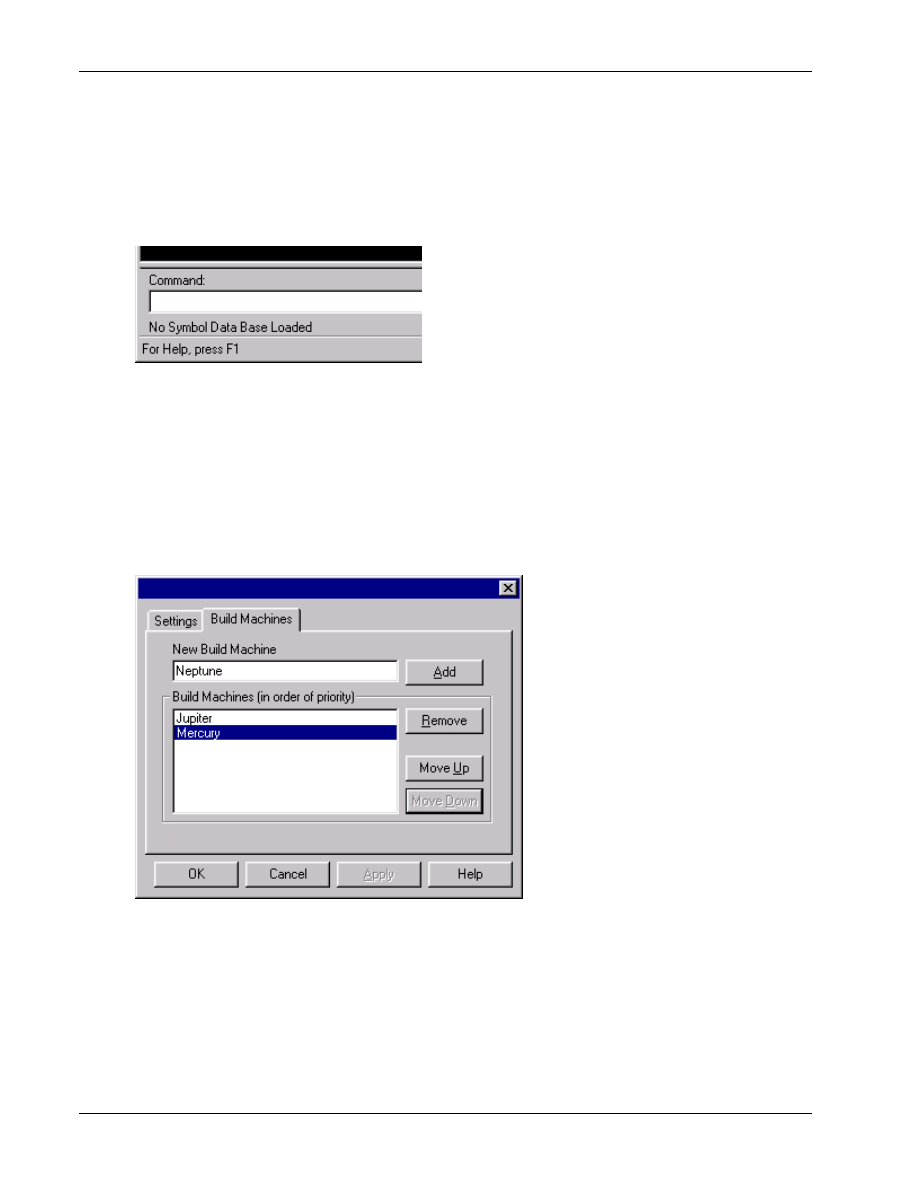
DWARF Server
QXDM Software Users Guide
10-4
QUALCOMM Proprietary
80-V1241-21 Rev. A
If the Build ID was not found in any of the specified machines, or if there are problems accessing the
1
ELF file, QXDM does not display the ELF filename in the status bar. Instead, a “No Symbol Data
2
Base Loaded” message is displayed in the status bar, as shown in Figure 10–3. In this case, QXDM
3
will not be able to support the feature of accessing Methods and Properties that are not defined in
4
.prop files.
5
6
Figure 10–3 No Symbol Data Base Loaded message
7
10.4 Configuring build machines in QXDM
8
To configure the Build Machine list in QXDM, select Options
→Settings→Build Machines tab. The
9
configuration dialog, as shown in Figure 10–4, allows you to add/remove Build Machine names and
10
reorder their priority.
11
12
Figure 10–4 Configure build machines
13

80-V1241-21 Rev. A
QUALCOMM Proprietary
11-1
11 Script Interface
QXDM supports a scripting API (Application Programming Interface) which uses OLE automation.
1
This interface can be used by any language that can access OLE automation objects. Examples are
2
Microsoft VBScript, Microsoft Visual Basic and Perl (needs ole.pm).
3
QXDM does not include any scripting language. Perl version 5.005_03 or newer can be installed from
4
ActiveState. Microsoft Windows Scripting host is integrated into Windows 98 and Windows 2000
5
and is available on Microsoft’s website to install on other operating systems.
6
The class identifier for the QXDM object is QXDM.Application and the default interface is called
7
IQxdm. Using this information, you can load the QXDM object from your script. For Example:
8
In Perl you can load the QXDM object and its default interface by the following-
9
use Win32::OLE;
10
my $qxdm_app = new Win32::OLE 'QXDM.Application';
11
In Microsoft VBScript you can load the QXDM object and its default interface by the following:
12
Dim myObject
13
myObject = CreateObject(“QXDM.Application”)
14
15
Once you have the QXDM object you can access all the automation interface functions directly. The
16
interface functions are divided into two categories. These are Properties and Methods.
17
The Properties are used to set or get a certain variable and can be treated like a class variable. For
18
example,
19
In Perl:
20
$qxdm_app->{LogMask} = “DEADBEAF”;
21
22
In Microsoft VBScript:
23
MyObject.LogMask = “DEADBEAF”
24
25
The Methods are used to issue commands and are written like basic function calls. For example,
26
In Perl:
27
$qxdm_app->QXDMTextOut(“This is a test string”);
28
29
In Microsoft VBScript:
30
MyObject.QXDMTextOut(“This is a test string”)
31
32

Script Interface
QXDM Software Users Guide
11-2
QUALCOMM Proprietary
80-V1241-21 Rev. A
QXDM contains 10 example Perl scripts named test00.pl through test09.pl and mashkeys.pl and 10
1
example Microsoft VBScript scripts named test00.vbs through test09.vbs and mashkeys.vbs. These
2
are in the automation directory where QXDM was installed.
3
The following QXDM functions can be called from scripts:
4
Properties:
5
BSTR LogMask
6
long
DataRate
7
long
DipSwitchMask
8
long
IsPhoneConnected
9
BSTR
ResponsePacket
10
Use this property to access the response packet after calling the
11
SendDmIcdPacket() method.
12
13
Methods:
14
void SendScript(BSTR Command)
15
void SetLoggingOn(BSTR MaskString)
16
void SetLoggingOff(BSTR FileName)
17
long
ResetPhone()
18
long
OfflineDigital()
19
void InjectDmIcdPacket(BSTR Packet, long Len)
20
void QXDMTextOut(BSTR TextString)
21
long SendDmIcdPacket(BSTR ReqPkt, long ReqLen, long tmo)
22
This function returns the response packet size. To access the response
23
packet itself, use the ResponsePacket property.
24
25

80-V1241-21 Rev. A
QUALCOMM Proprietary
12-1
12 QXDM Command-prompt Functions
The following additional commands can be invoked via the Command window, in addition to the
1
regular script commands described in the Script Help display:
2
■
@<method name> – See Chapter 9 for details.
3
■
get_property – Read a property from the phone. See Chapter 7 for a description of properties.
4
Syntax: get_property <Property Name>
5
Example:
6
get_property version.voc_maj
7
version.voc_maj = 0x65
8
■
print_property – Print a property definition. Refer to the Properties chapter for a description of
9
properties.
10
Syntax: print_property <Property Name>
11
Example:
12
print_property time
13
# Element Name, Offset, Size, Description, Type[, Request Value]
14
# Property Name: time; ID: 29; Size: 9; Type: Diagnostic Packet
15
time.cmd_code, 0, 1, Timestamp, HEX, 0x1d
16
time.time_stamp, 1, 8, , HEX
17
time.time_stamp[0], 1, 4, , HEX
18
time.time_stamp[1], 4, 4, , HEX
19
20

QXDM Command-prompt Functions
QXDM Software Users Guide
12-2
QUALCOMM Proprietary
80-V1241-21 Rev. A
■
list_properties – List the currently supported properties or properties matching a given pattern.
1
See Chapter 7 for a description of properties.
2
Syntax: list_properties [part of a property name]
3
Example:
4
list_properties s*
5
ser ID: 45 DIAG type
6
srch2 ID: 15 Log type
7
srch_fing ID: 45 Log type
8
state ID: 63 DIAG type
9
status ID: 12 DIAG type
10
sup_fer ID: 85 DIAG type
11
sup_walsh_codes ID: 86 DIAG type
12
svc_config ID: 46 Log type
13
■
put_property – Write a property to the phone. See Chapter 7 for a description of properties.
14
Syntax: put_property <Property Name> <property arguments>
15
Example:
16
put_property ftm_acquire 100 10 0 0 0
17
■
send_is801_message – Send an IS-801 message to the phone. See Chapter 14 for details.
18
■
exit – Exit QXDM.
19
■
sia_remote_control – Start an SIA remote control session.
20
Syntax: sia_remote_control <hostname> <ESN/MIN> <repetitions>
21
Example:
22
sia_remote_control zeus 7605551212 0
23
■
cdm_start_log – Start logging simple property objects to the CDM (CDMA DM).
24
Syntax: cdm_start_log <Property Name Field>
25
Example:
26
cdm_start_log srch_fing.pilot_off
27
■
cdm_stop_log Stop logging simple property objects to the CDM (CDMA DM).
28
Syntax: cdm_stop_log <Property Name Field>
29
Example:
30
cdm_stop_log srch_fing.pilot_off
31
■
wait_event – Wait until a requested event arrives from the phone or timeout occurs. The timeout
32
is defined in Communication
→Settings→Script Cmd Timeout.
33
Syntax: wait_event EVENT_NAME
34
Example:
35
wait_event EVENT_CDMA_CH_CHANGE
36
37
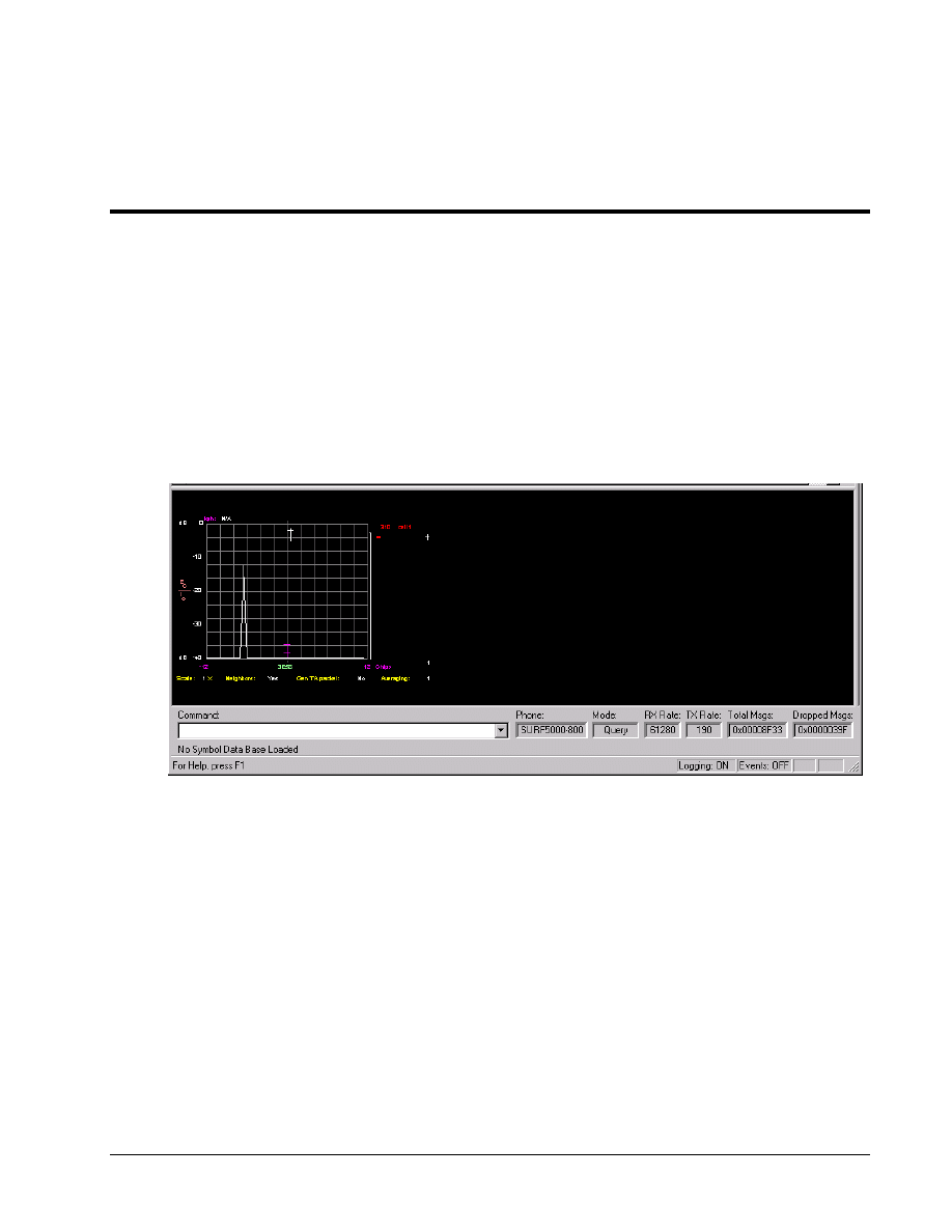
80-V1241-21 Rev. A
QUALCOMM Proprietary
13-1
13 Temporal Analyzer
13.1 Temporal Analyzer display
1
To view the temporal analyzer display, as shown in Figure 13–1, select Temporal Analyzer from the
2
middle drop-down menu on the splitter view bar (see Figure 4–6).
3
4
Figure 13–1 Temporal Analyzer display
5
For the cdma2000 1x subscriber station, the fingers that belong to the F-FCH active set and the
6
F-SCH active set are distinguished on the temporal analyzer display by different colors.
7
Once the Temporal Analyzer view has been selected from the middle drop-down menu, the following
8
graphs are accessible by either a right-click or via the Temporal Analyzer menu.
9
10
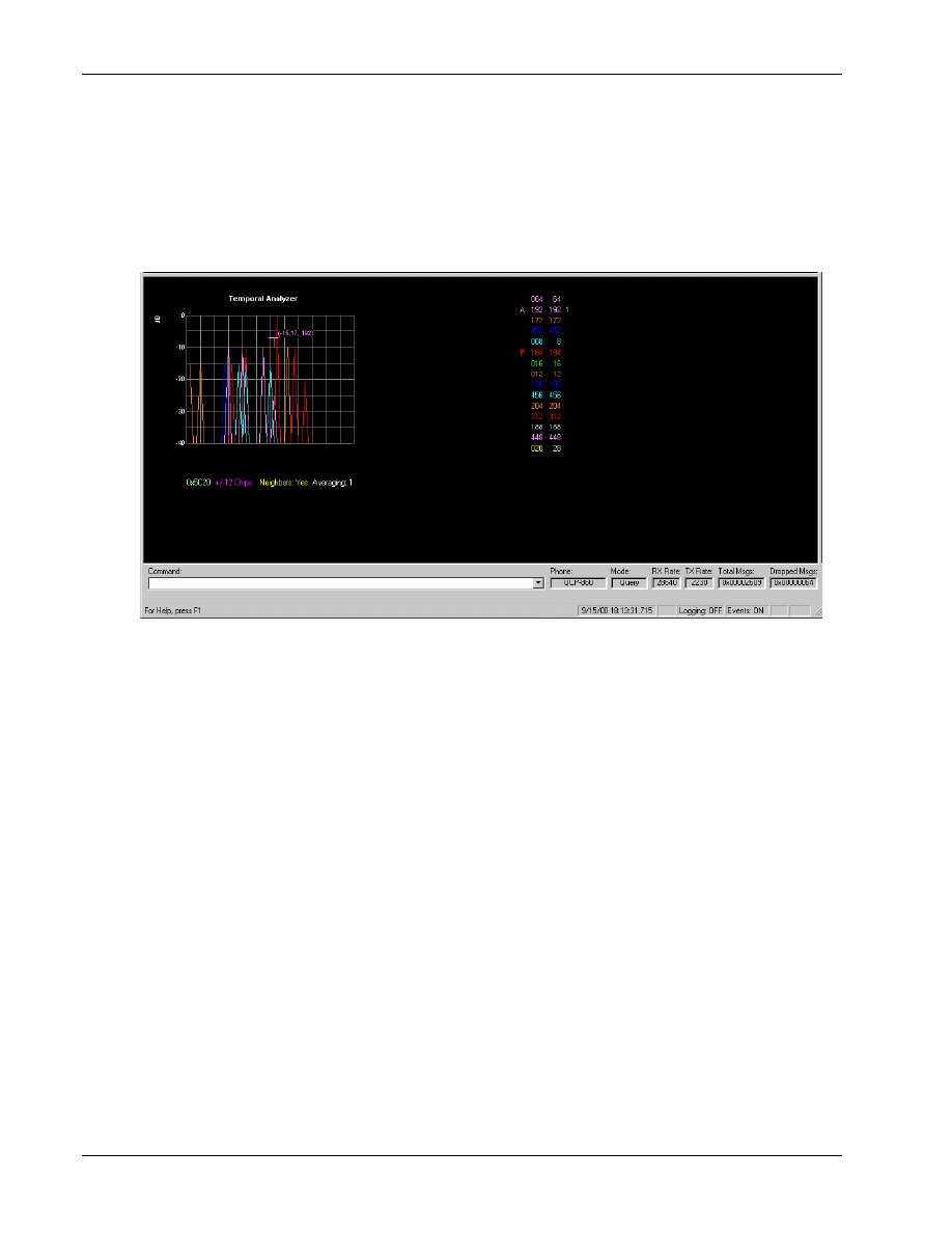
Temporal Analyzer
QXDM Software Users Guide
13-2
QUALCOMM Proprietary
80-V1241-21 Rev. A
13.2 Pilot Sets display
1
This screen, as shown in Figure 13–2, displays the pilots belonging to the Active (A), Candidate (C),
2
Precandidate (P), and Neighbor sets, as well as the PN offset values.
3
4
Figure 13–2 Pilot Sets display
5
6
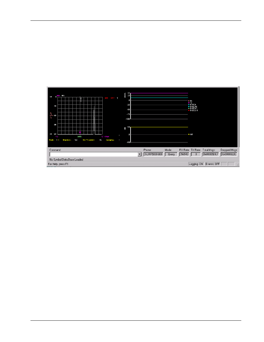
QXDM Software Users Guide
Temporal Analyzer
80-V1241-21 Rev. A
QUALCOMM Proprietary
13-3
13.3 Transmit/Receive (Tx/Rx) Adjusted Power display
1
This screen, as shown in Figure 13–3, displays both the received and transmitted power, as well as the
2
amount the transmitted power is adjusted during a specified averaging period. For the cdma2000 1x
3
subscriber station, it also displays the transmit power separately for each reverse link channel, that is,
4
R-FCH, R-SCH0, R-SCH1, and R-DCCH.
5
6
Figure 13–3 Transmit/Receive (Tx/Rx) Power display
7
8
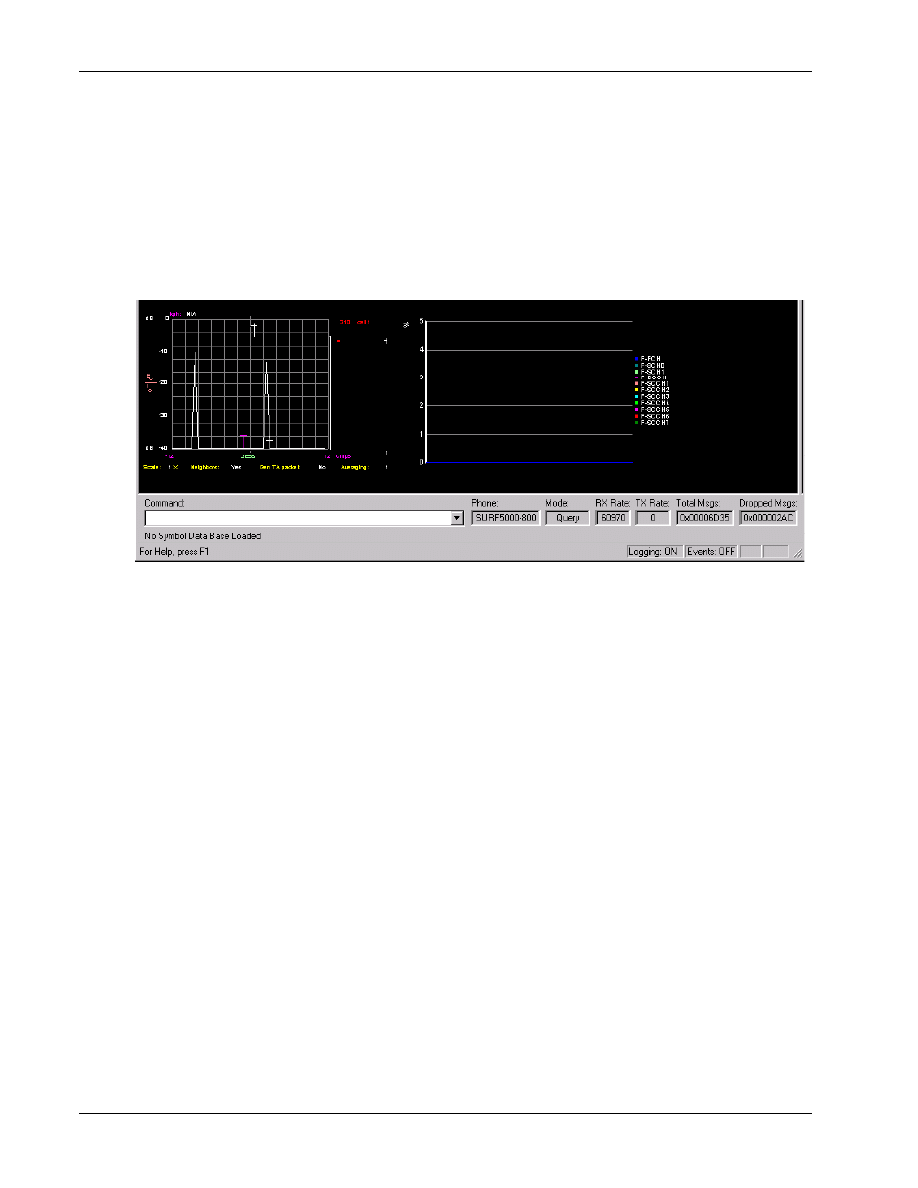
Temporal Analyzer
QXDM Software Users Guide
13-4
QUALCOMM Proprietary
80-V1241-21 Rev. A
13.4 Frame Error Rate (FER) display
1
The frame error rate (FER) display screen, as shown in Figure 13–4, displays the percentage of steady
2
state errors over a specified period of time. For the cdma2000 1x subscriber station, it displays the
3
FER for each forward link channel, that is, F-FCH, F-SCH0, F-SCH1, F-SCCH1, F-SCCH2,
4
F-SCCH3, F-SCCH4, F-SCCH5, F-SCCH6, and F-SCCH7.
5
6
Figure 13–4 Frame Error Rate (FER) display
7
8
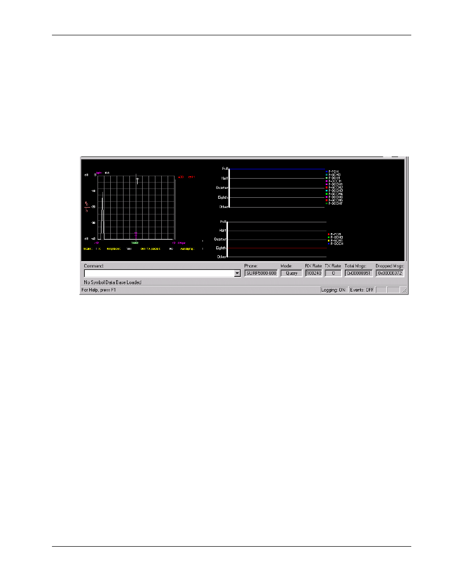
QXDM Software Users Guide
Temporal Analyzer
80-V1241-21 Rev. A
QUALCOMM Proprietary
13-5
13.5 Frame Types (old Tx/Rx Vocoder Rate) display
1
This screen, as shown in Figure 13–5, displays the received and transmitted signal vocoder rate over a
2
specified period of time. For the cdma2000 1x subscriber station, it displays the frame type rates for
3
each forward link channel, that is, F-FCH, F-SCH0, F-SCH1, F-SCCH1, F-SCCH2, F-SCCH3,
4
F-SCCH4, F-SCCH5, F-SCCH6, and F-SCCH7, and the frame type rates for each reverse link
5
channel, that is, R-FCH, R-SCH0, R-SCH1, and R-DCCH.
6
7
Figure 13–5 Frame Types (old Tx/Rx Vocoder Rate) display
8
9
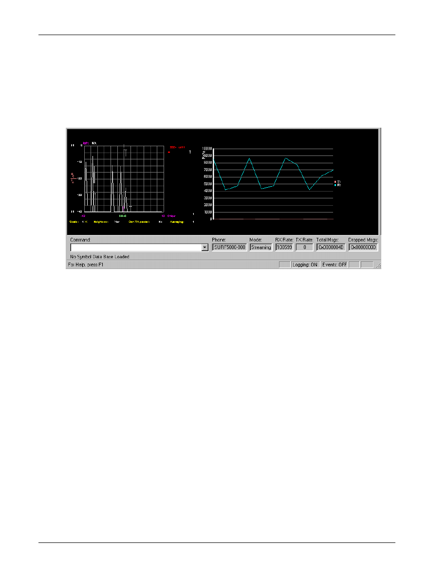
Temporal Analyzer
QXDM Software Users Guide
13-6
QUALCOMM Proprietary
80-V1241-21 Rev. A
13.6 RLP Throughput display
1
This screen, as shown in Figure 13–6, displays a graph of RLP receive and transmit throughput (the
2
number of bytes received and transmitted over a specified period of time).
3
4
Figure 13–6 RLP Throughput display
5
6
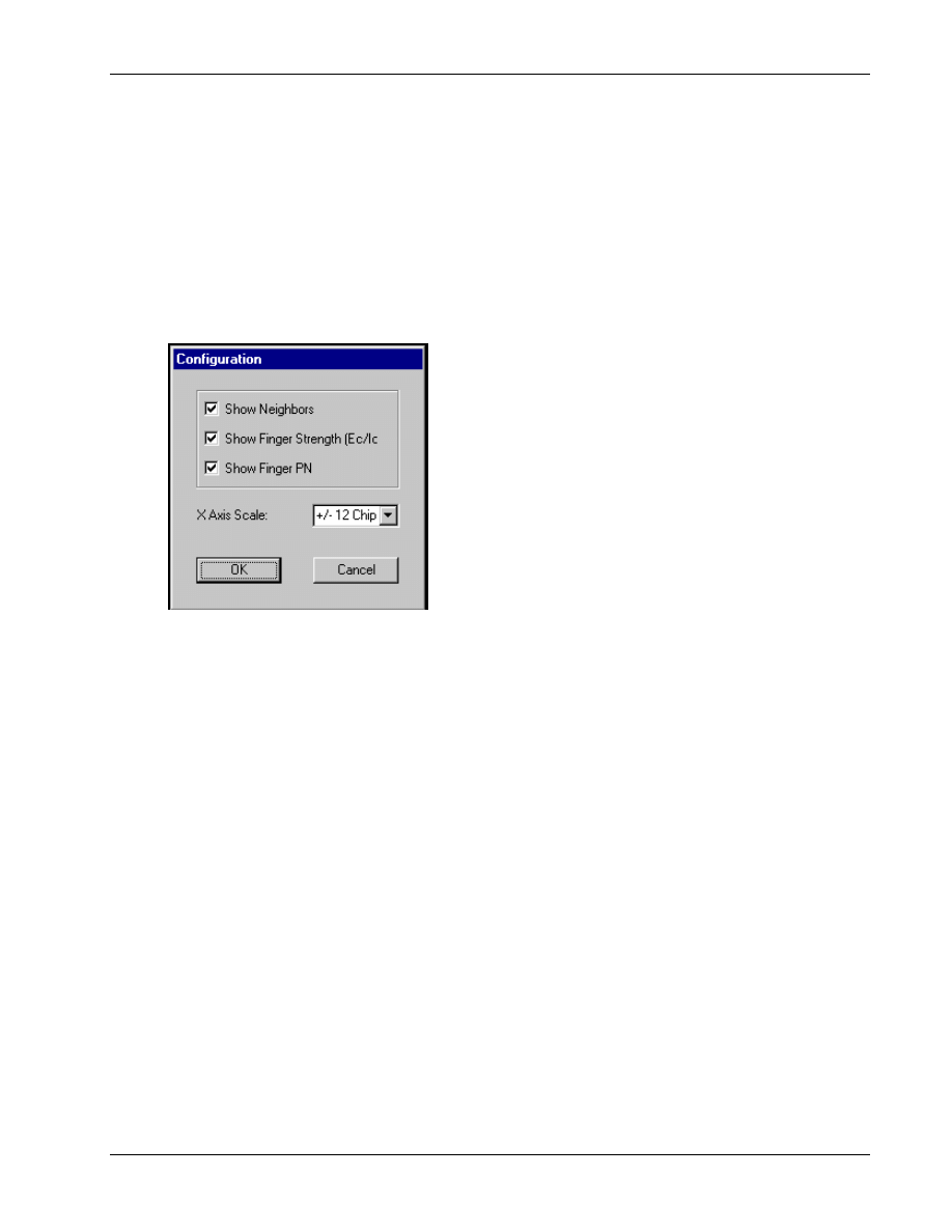
QXDM Software Users Guide
Temporal Analyzer
80-V1241-21 Rev. A
QUALCOMM Proprietary
13-7
13.7 Temporal Analyzer Configuration
1
You can configure the way information appears in the temporal analyzer display by using the
2
Configuration dialog shown in Figure 13–7. You can access this dialog by either a right-click or via
3
the Temporal Analyzer menu.
4
To configure the display, select various options in the Configuration dialog, then click
OK
to activate
5
the selections.
6
7
Figure 13–7 Temporal Analyzer
→ Configuration
8
9

Temporal Analyzer
QXDM Software Users Guide
13-8
QUALCOMM Proprietary
80-V1241-21 Rev. A
1
80-V1241-21 Rev. A
QUALCOMM Proprietary
14-1
14 Application Screens
1
NOTE
Numerous changes have been made to this chapter. It is recommended that you review it in its
entirety.
2
14.1 Application screens
3
Table 14-1 is a listing of the properties and packets utilized by QXDM’s displays. Most of the screens
4
are HTML- and JavaScript-based. While they are viewed using QXDM, they are not part of the
5
QXDM program itself. See Section 4.3 for information on how to access these screens. Refer to the
6
CDMA DMSS Serial Data Interface Control Document, 80-V1294-1, for specific descriptions of the
7
properties and packets.
8
Some of the display names in Table 14-1 may have superscripted numbers following them. These
9
numbers indicate the note information that follows the table.
10
Table 14-1 Properties and packets
11
Display name
Packet ID
[decimal #]
Packets/properties used
Pkt
type
Prop file
Active set information
0x1093 [147] aset_info
Log aset_info
0x10C6
[198]
aset_info_ver_2 Log
aset_info
Bluetooth logs
0x103E [62]
bt_gen
Log
btLogs
0x103F
[63]
bt_bb_gen Log
btLogs
0x1040
[64]
bt_bb_dev Log
btLogs
0x1041
[65]
bt_lm
Log
btLogs
0x1042
[66]
bt_l2
Log
btLogs
0x1043
[67]
bt_sdp Log
btLogs
0x1044
[68]
bt_rc_session Log
btLogs
0x1045
[69]
bt_rc_dlci Log
btLogs
0x1046
[70]
bt_ag Log
btLogs

Application Screens
QXDM Software Users Guide
14-2
QUALCOMM Proprietary
80-V1241-21 Rev. A
Display name
Packet ID
[decimal #]
Packets/properties used
Pkt
type
Prop file
Factory test mode
0x103A
[58]
ftm_log
Log
ftm_log
Sub_cmd: (100)
0x3B [59]
ftm_acquire
Diag
ftm
(102)
0x3B [59]
ftm_assign_fwd_fch
Diag
ftm
(103)
0x3B [59]
ftm_assign_fwd_sch
Diag
ftm
(104)
0x3B [59]
ftm_assign_rev_fch
Diag
ftm
(105)
0x3B [59]
ftm_assign_rev_sch
Diag
ftm
(109)
0x3B [59]
ftm_set_mode
Diag
ftm
(110)
0x3B [59]
ftm_assign_fwd_dcch
Diag
ftm
(111)
0x3B [59]
ftm_assign_rev_dcch
Diag
ftm
Fast forward power
control
0x102B [43]
ffpc
Log
ffpc
Full test data service
0x103D
[61] tdso_full
Log
tdso_full
0x109A
[154]
ftdso_p2
Log
ftdso_p2
0x70
[112]
is2000_status
Diag
status2k
0x72
[114]
reset_tdso Diag
tdso_full
gpsOne
[108]
gps_sess_ctrl
Diag
gpsone
Sub_cmd: (0)
0x6C [108]
gps_sess_ctrl_start
Diag
gpsone
(1) 0x6C
[108]
gps_sess_ctrl_acq
Diag
gpsone
(2) 0x6C
[108]
gps_sess_ctrl_sense
Diag
gpsone
(5) 0x6C
[108]
gps_sess_ctrl_pl
Diag
gpsone
(8) 0x6C
[108]
gps_sess_ctrl_almanac
Diag
gpsone
(9) 0x6C
[108]
gps_sess_ctrl_ephemeris Diag
gpsone
0x6D
[109]
gps_search_grid
Diag
gpsone
GPS statistics
0x1038
[56]
gps_stats
Log
gps_stats
0x6E
[110]
gps_statistics
Diag
gpsone
HDR
■
Air link summary
0x1068 [104]
Log
0x1069
[105]
Log
■
Fingers
0x1064 [100]
hdr_finger_data
Log
hdrlog
■
Fwd statistics
0x105F [95]
hdr_asp
Log
hdrlog
0x1061
[97]
hdr_drc_arq_buffer
Log
hdrlog
0x1064
[100]
hdr_finger_data
Log
hdrlog
0x1067
[103]
hdr_ftc_rate_count
Log
hdrlog
0x106F
[111]
hdr_page_msg
Log
hdrlog
0x107F
[127]
hdr_fwd_rate_stat Log
hdrlog
Subsys id/cmd: (5/4)
0x4B [75] hdr_reset_page_msg_cnt
Diag
hdrlog
(5/1)
0x4B
[75]
hdr_reset_fwd_stats
Diag
hdrlog
■
Pilot sets
0x107A [122] hdr_pilot_sets
Log hdrlog
0x1064 [100]
hdr_finger_data Log
hdrlog

QXDM Software Users Guide
Application Screens
80-V1241-21 Rev. A
QUALCOMM Proprietary
14-3
Display name
Packet ID
[decimal #]
Packets/properties used
Pkt
type
Prop file
■
Protocol summary
0x107E [126] hdr_state_info
Log hdrlog
0x106B
[107]
hdr_session_attempt
Log
hdrlog
0x106E[110]
hdr_conn_attempt
Log
hdrlog
Subsys id/cmd: (5/5)
0x4B [75]
hdr_reset_session_atmpt_cnt Diag
hdrlog
(5/2)
0x4B
[75]
hdr_reset_conn_atmpt_cnt Diag
hdrlog
■
Rev statistics
0x1060 [96]
hdr_rl_pkt_summary Log
hdrlog
0x1062
[98]
hdr_rtc_rate_cnt Log
hdrlog
0x106C
[108]
hdr_access_attempt
Log
hdrlog
0x107E
[126]
hdr_state_info
Log
hdrlog
Subsys id/cmd: (5/2)
0x4B [75] hdr_reset_rev_stats
Diag
hdrlog
(5/0)
0x4B
[75]
hdr_reset_access_atmpt_cnt Diag
hdrlog
■
RLP statistics
0x1070 [112]
hdr_rlp_stats
Log
hdrlog
Subsys id/cmd: (5/6)
0x4B [75] hdr_reset_rlp_stats
Diag
hdrlog
■
Status 0x105F
[95] hdr_asp
Log
hdrlog
0x1062
[98]
hdr_rtc_rate_cnt Log
hdrlog
0x1064
[100]
hdr_finger_data
Log
hdrlog
0x107A
[122]
hdr_pilot_sets Log
hdrlog
0x107E
[126]
hdr_state_info
Log
hdrlog
0x107F
[127]
hdr_fwd_rate_stat Log
hdrlog
0x1080
[128]
hdr_sector_info
Log
hdrlog
Subsys id/cmd: (5/7)
0x4B [75]
hdr_at_config
Diag
hdrlog
0xC
[12]
status Diag
status
■
Temporal analyzer
0x107D [125]
hdr_gen_ta
Log
hdr_gen_ta
Log priorities
Sub_cmd
0x61 [97]
log_priorities_req
Diag
logPriorities
(2) 0x61
[97]
log_priorities_rsp
Diag
logPriorities
[26]
markov
Diag
markov
0x1B
[27]
DIAG_MARKOV_RESET_F Diag
MDR statistics
0x56 [86]
sup_walsh_codes Diag
sup_walsh_codes
MSP
Subsys id/cmd: (1/1)
0x4B [75]
DIAG_ZREX_SET_LOG_
MASK_F
Diag
(1/3)
0x4B
[75]
DIAG_ZREX_DRIVER_INFO_F Diag
(1/4)
0x4B
[75]
DIAG_ZREX_SW_VERSIONS_F Diag
(1/5)
0x4B
[75]
DIAG_ZREX_TOUCHSCREEN_
EMU_F
Diag
(1/6)
0x4B
[75]
DIAG_ZREX_LAUNCH_ZX_F
Diag

Application Screens
QXDM Software Users Guide
14-4
QUALCOMM Proprietary
80-V1241-21 Rev. A
Display name
Packet ID
[decimal #]
Packets/properties used
Pkt
type
Prop file
MUX statistics
[112]
is2000_status
Diag
status2k
Sub_cmd: (1)
0x62 [98]
diag_parm_retrieve_is2k_std
Diag
parm_retrieve
(3) 0x62
[98]
diag_parm_retrieve_is2k_ext
Diag
parm_retrieve
(1) 0x62
[98]
diag_parm_retrieve_dcch Diag
parm_retrieve
(1) 0x62
[98]
diag_parm_retrieve_lower Diag
parm_retrieve
MUX1 trfc & Layer2
stats
0x43 [67]
IS95Aparam
Diag
IS95Aparam
MUX2 trfc & sec stats
[67]
IS95Aparam
Diag
IS95Aparam
MUX2 trfc ch stats
[67] IS95Aparam
Diag
IS95Aparam
NV items
See prop file for complete list.
Diag
nv_items
Paging & access stats
[67]
IS95Aparam
Diag IS95Aparam
Quick paging channel
0x1030 [48]
qpch
Log
qpch
Register peek/poke
[0]
version
Diag
version
See prop file for complete list.
Abs
Addr
msm3000_registers
and
msm5000_registers
Retrievable parameters
Sub_cmd: (3)
0x62 [98]
diag_parm_retrieve_is2k_ext
Diag
parm_retrieve
(1) 0x62
[98]
diag_parm_retrieve_is2k_std
Diag
parm_retrieve
(1) 0x62
[98]
diag_parm_retrieve_lower Diag
parm_retrieve
(1) 0x62
[98]
diag_parm_retrieve_upper Diag
parm_retrieve
(0) 0x62
[98]
diag_parm_retrieve_range_std
Diag
parm_retrieve
(2) 0x62
[98]
diag_parm_retrieve_range_ext
Diag
parm_retrieve
(1) 0x62
[98]
diag_parm_retrieve_dcch Diag
parm_retrieve
RLP3 statistics logging
0x1031
[49] rlpstats
Log rlpstats
0x71
[113]
reset_rlpstats
Diag
rlpstats
0x70
[112]
is2000_status
Diag
status2k
SBI data access
0x75 [117]
DIAG_SBI_READ_F
Diag
0xE4
[228]
DIAG_SBI_WRITE_F Diag
Script help
Uses no properties
Searcher & finger
information
0x102D [45]
srch_fing Log
srch_fing
Security services SSL
sessions
0x10A9 [169]
ssl_session_info
Log
QXDM database
0x10AA[170]
ssl_session_info
Log
QXDM
database
0x10AB171]
ssl_session_info
Log
QXDM
database
0x10AC[172]
ssl_session_stats
Log
QXDM
database
0x10AD[173]
ssl_tx_stats Log
QXDM
database
0x10AE[174]
ssl_rx_stats
Log
QXDM
database

QXDM Software Users Guide
Application Screens
80-V1241-21 Rev. A
QUALCOMM Proprietary
14-5
Display name
Packet ID
[decimal #]
Packets/properties used
Pkt
type
Prop file
Service configuration
info
0x10C5 [197]
svc_config_ver_2
Log
svc_config
0x102E
[46]
svc_config Log
svc_config
Simple test data
service
0x1032 [50]
tdso
Log
tdso
0x1099
[153]
stdso_p2 Log
stdso_p2
0x70
[112]
is2000_status
Diag
status2k
0x72
[114]
reset_tdso Diag
tdso_full
Status 0x70
[112]
is2000_status
Diag
status2k
Subsys id/cmd: (4/0)
0x4B [75]
wcdma_version
Diag
wcdma_version
0x0
[0]
version
Diag
version
0xC
[12]
status Diag
status
0x3F
[63]
state Diag
state
0x1019
[25]
genta
Log
genta
Temporal analyzer
0x100B [11]
LOG_FING_C
Log
0x100C
[12]
LOG_SRCH_C
Log
0x100F
[15]
LOG_SRCH2_C
Log
0x1013
[19]
LOG_ACC_INFO_C
Log
0x1019
[25]
LOG_GENRL_TA_C
Log
0x1029
[41]
LOG_FWD_FRAME_TYPES_C
Log
0x102A
[42]
LOG_REV_FRAME_TYPES_C
Log
0x102C
[44]
LOG_REV_PCTRL_C
Log
0x102D
[45]
LOG_SRCH_FING_INFO_C
Log
0x1031
[49]
LOG_RLP_STAT_C
Log
WCDMA
■
0x4105
[261]
WCDMA_AGC_C
Log
■
Block error rate
0x4116 [278]
dl_trch_bler
Log
wcdma_l1
■
Layer1 state
0x4104 [260]
wcdma_finger_ta
Log
wcdma_Finger
0x410A
[266]
common_dl_phychan
Log
achannels
0x410C
[268]
ul_dpch
Log
achannels
0x4110
[272]
aset
Log
achannels
0x4111
[273]
nset
Log
achannels
0x412E
[302]
set_ref_pos Log
achannels
■
MAC channel
mapping
0x411D [285]
wcdma_dl_mac_cfg
Log
maclog
0x4117
[279]
wcdma_ul_mac_cfg
Log
maclog
■
MAC parameters
0x4123 [291]
mac_rach_cfg
Log
maclog
0x4117
[279]
wcdma_ul_mac_cfg
Log
maclog
0x411D
[285]
wcdma_dl_mac_cfg
Log
maclog

Application Screens
QXDM Software Users Guide
14-6
QUALCOMM Proprietary
80-V1241-21 Rev. A
Display name
Packet ID
[decimal #]
Packets/properties used
Pkt
type
Prop file
■
NAS CS connection
mgmt
0x4137 [311]
wcdma_nas_cs_connection_bc
Log
wcdma_l4
0x4133
[307]
wcdma_cs_call_info
Log
wcdma_l4
■
NAS errors
0x413C [316]
wcdma_nas_error_message
Log
wcdma_l4
■
NAS mobility mgmt
0x4131 [305]
wcdma_nas_mm_state
Log
wcdma_l4
0x4130
[304]
wcdma_nas_gmm_state
Log
wcdma_l4
0x4132
[306]
wcdma_nas_reg_state
Log
wcdma_l4
0x4135
[309]
wcdma_mm_info
Log
wcdma_l4
0x4138
[312]
wcdma_nas_ue_dynamic_id
Log
wcdma_l4
0x4139
[313]
wcdma_nas_ue_static_id
Log
wcdma_l4
■
NAS PS connection
mgmt
0x4136 [310]
wcdma_nas_ps_connection_qos
Log
wcdma_l4
0x4134
[308]
wcdma_ps_call_info
Log
wcdma_l4
■
Physical channels
0x410C [268]
ul_dpch
Log
achannels
0x410D
[269]
ul_phychan_prach
Log
wcdma_prach
0x410A
[266]
common_dl_phychan
Log
achannels
0x410B
[267]
ded_dl_phychan
Log
achannels
■
RLC DL AM channel
parameters
0x4122 [290]
wcdma_rlc_dl_am
Log
wcdma_rlc_layer
0x411E
[286]
wcdma_rlc_dl_ciphering
Log
wcdma_rlc_layer
■
RLC DL TM channel
parameters
0x4120 [288]
wcdma_rlc_dl_tm
Log
wcdma_rlc_layer
■
RLC DL UM channel
parameters
0x4121 [289]
wcdma_rlc_dl_um
Log
wcdma_rlc_layer
■
RLC Log channel
setup UL/DL
0x4117 [279]
wcdma_ul_mac_cfg
Log
maclog
0x4119
[281]
wcdma_rlc_ul_state
Log
wcdma_rlc_layer
0x411D
[285]
wcdma_dl_mac_cfg
Log
maclog
0x411F
[287]
wcdma_rlc_dl_state
Log
wcdma_rlc_layer
■
RLC UL AM channel
parameters
0x411C [284]
wcdma_rlc_ul_am
Log
wcdma_rlc_layer
0x4118
[280]
wcdma_rlc_ul_ciphering
Log
wcdma_rlc_layer
■
RLC UL TM channel
parameters
0x411A [282]
wcdma_rlc_ul_tm
Log
wcdma_rlc_layer
■
RLC UL UM channel
parameters
0x411B [283]
wcdma_rlc_ul_um
Log
wcdma_rlc_layer
■
RRC status
0x4126 [294]
wcdma_rrc_protocol_errors
Log
wcdma_rrc
0x412B
[299]
wcdma_sib Log
wcdma_rrc
0x4127
[295]
wcdma_cell_id
Log
wcdma_rrc
0x4125
[293]
wcdma_rrc_modes_and_states
Log
wcdma_rrc
■
Temporal analyzer
0x4104 [260]
WCDMA_FINGER_TA_INFO_C
Log
wcdma_Finger
■
TFCS downlink
0x4115 [277]
dl_tfcs
Log
wcdma_l1

QXDM Software Users Guide
Application Screens
80-V1241-21 Rev. A
QUALCOMM Proprietary
14-7
Display name
Packet ID
[decimal #]
Packets/properties used
Pkt
type
Prop file
■
TFCS uplink
0x4124 [292]
wcdma_mac_ul_tfcs_cfg
Log
maclog
0x4117
[279]
wcdma_ul_mac_cfg
Log
maclog
■
Transport channels
0x4108 [264]
dl_cctch
Log
wcdma_dl_cctrch
0x4109
[265]
ul_cctrch Log
wcdma_ul_cctrch
1
The following sections are note information for Table 14-1.
2
14.1.1 Note 1
3
See Factory Test Mode Application Note, CL93-V1974-1, for specific descriptions
4
14.1.2 Note 2
5
The combo box will dynamically show which rate set is being used if the Autodetect box is checked.
6
If no rate set can be detected, the combo box will contain Rate Set Unknown. If the user unchecks the
7
Autodetect box and sets the combo box to a particular rate set, the values will only refresh if the
8
selected rate is in use or if it is unknown.
9
14.1.3 Note 3
10
gpsOne – A new command,
send_is801_message
, can be used on the QXDM command line to
11
send IS-801 messages to the phone. The syntax for the command is as follows (square brackets
12
indicate an optional parameter):
13
send_is801_message <GpsControl> <FileName> [<SetBitOption>]
14
<GpsControl>
defines messages for acquisition assistance, sensitivity assistance, and position
15
location response.
16
<FileName>
is the name of a file containing text data in the struct iteration language toolkit (SILK)
17
input format, describing the IS-801 message fields. Example input file templates are located in the
18
QXDM\reference folder of the QXDM installation.
19
20
CAUTION
The templates have values that work with SILK. Providing incorrect values may cause QXDM to
hang while the SILK functions wait for additional data.
21
Include the
<SetBitOption>
parameter to give the mobile additional information.
22
Application Screens
QXDM Software Users Guide
14-8
QUALCOMM Proprietary
80-V1241-21 Rev. A
The values for the
<GpsControl>, <FileName>,
and (optional)
<SetBitOption>
parameters
1
must be grouped as shown in Table 14-2.
2
Table 14-2 Required syntax for send_is801_message
3
IS-801 message
Command
send_is801 message <GpsControl> <FileName> <SetBitOption>
Acquisition assistance
send_is801_message 1 silkspecAA.txt UseMessageTime
Sensitivity assistance
send_is801_message 2 silkspecSA.txt WipeOff
Provide position location
response
send_is801_message 5 silkspecPL.txt (Reserved)
Provide Almanac data
send_is801_message 8 silkspecAlmanac.txt (Reserved)
Provide Ephemeris data
send_is801_message 9 silkspecEphemeris.txt (Reserved)
4
The gpsOne screen displays the gpsOne commands. Refer to the CDMA DMSS Serial Data Interface
5
Control Document, 80-V1294-1, for diag message descriptions. Refer to the gpsOne Position
6
Determination Messaging and Parameters document for a description of the IS-801 message fields.
7
14.1.4 Note 4
8
GPS statistics – Refer to the CDMA DMSS Serial Data Interface Control Document, 80-V1294-1, for
9
specific GPS Statistics log record descriptions. In addition to the fields, the following calculations are
10
displayed:
11
■
% Successful Sessions (Yield) = NUM_SUCCESSFUL_SESSIONS/NUM_SESSIONS
12
■
Current Lat Error = TRUE_LAT – LAT
13
■
Current Long Error = TRUE_LONG – LONG
14
■
Current Height Error = TRUE_HEIGHT – HEIGHT
15
■
Current Error =
2
2
_
_
LAT
error
LONG
error
+
16
■
BIAS =
2
2
_
_
NUM_SUCCESSFUL_SESSIONS
NUM_SUCCESSFUL_SESSIONS
LAT
error
LONG
error
∑
∑
+
17
■
NUM_SUCCESSFUL_SESSIONS = Sum of SUCCESS_TYPE = PD_SUCCESS
18
■
68% cdf accuracy = calculated numerically by ordering the successful samples by error, and
19
taking the 68th percentile
20
■
95% cdf accuracy = calculated numerically by ordering the successful samples by error, and
21
taking the 95th percentile
22
■
TOTAL_TIME_TO_FIX = sum of TIME_TO_FIX
23
■
Average time to fix = TOTAL_TIME_TO_FIX/NUM_SUCCESSFUL_SESSIONS
24
■
NUM_SESSIONS = sum of session log records
25

QXDM Software Users Guide
Application Screens
80-V1241-21 Rev. A
QUALCOMM Proprietary
14-9
■
Sessions per AA = NUM_SESSIONS/NUM_AA_GETS
1
■
Sessions per SA = NUM_SESSIONS/NUM_SA_GETS
2
■
Average tune away time = TIME_TUNE_AWAY/NUM_TUNE_AWAY
3
■
% tune away time < 100ms = NUM_100MS * 100/NUM_SUCCESSFUL_SESSIONS
4
■
% tune away time < 500ms = NUM_400MS * 100/NUM_SUCCESSFUL_SESSIONS
5
■
% tune away time < 2100ms = NUM_1600MS * 100/NUM_SUCCESSFUL_SESSIONS
6
14.1.5 Note 5
7
The Log Priorities display is used to change the priority at which messages and logs are sent from a
8
streaming phone by setting different priority values.
9
14.1.6 Note 6
10
The Markov Statistics screen displays statistics generated while making a Markov call. Clicking
11
Reset
will reset the Markov values on the phone.
12
14.1.7 Note 7
13
The MUX2 Traffic Channel and Secondary Statistics screen displays the MUX2 traffic channel and
14
secondary statistics when making a call. Clicking
Reset
will reset the values on the phone.
15
14.1.8 Note 8
16
The MUX2 Traffic Channel Statistics screen displays the MUX2 traffic channel statistics when
17
making a call. Clicking
Reset
will reset the values on the phone.
18
14.1.9 Note 9
19
The NV Items display allows you to read and write NV items. NV items are grouped by categories.
20
When you select a category, only the NV items within that category are displayed.
21
When you click an NV item, it will expand to display the names and values of all fields within the
22
item. Click
Read
to reread the current value of the selected NV item. After modifying the values,
23
click
Write
to write the updated values back to the phone.
24
14.1.10 Note 10
25
The Paging and Access Statistics screen displays the paging channel and access channel statistics.
26
Clicking
Reset
will reset the values on the phone.
27
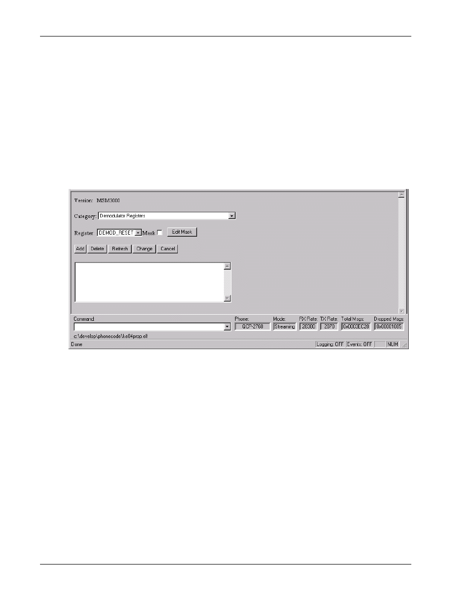
Application Screens
QXDM Software Users Guide
14-10
QUALCOMM Proprietary
80-V1241-21 Rev. A
14.1.11 Note 11
1
Register peek/poke provides a convenient way for developers to peek and poke into the MSM
2
registers. This provides functionality similar to the memory peek/poke (see Section 4.4.5 for more
3
information). By selecting the register name, you can observe the register contents at run-time instead
4
of having to enter the register address. You can also modify the register contents and observe the
5
effect on the phone operation. Each register can have an associated mask. In addition to viewing and
6
editing, you can specify whether the mask is applied when changing the register contents.
7
The MSM register set is automatically loaded according to the mobile model when QXDM is
8
connected to the FFA or SURF. Note that the screen is not updated continuously. You must click
9
Refresh
to refresh the values. Figure 14–1 illustrates the register peek/poke view.
10
11
Figure 14–1 Register Peek/Poke Viewer
12
Category
13
Lists the register functional groupings.
14
Register
15
Lists the MSM registers within the selected category.
16
Mask
17
This check box indicates whether or not the mask is applied when modifying the register contents.
18
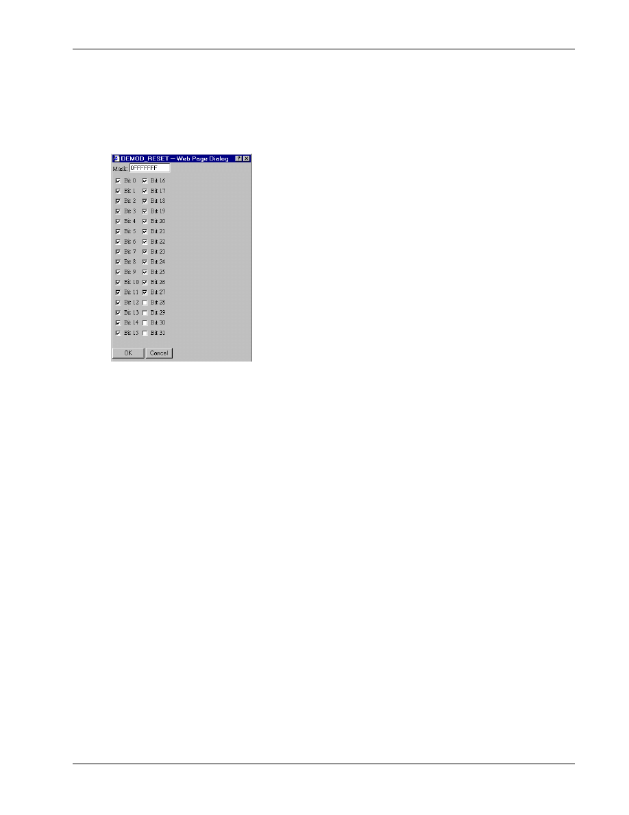
QXDM Software Users Guide
Application Screens
80-V1241-21 Rev. A
QUALCOMM Proprietary
14-11
Edit mask
1
Used to view and edit the mask associated with the selected register in a Mask dialog, as shown in
2
3
4
Figure 14–2 Mask dialog
5
Add
6
Adds the selected register to the edit screen to view the register contents.
7
Delete
8
Deletes the last added register.
9
Refresh
10
Refreshes all selected register contents.
11
Change
12
Used to apply the change after editing the register contents. You can also press E
NTER
to apply the
13
change.
14
Cancel
15
Used to discard the change. You can also press C
ANCEL
to discard the change.
16

Application Screens
QXDM Software Users Guide
14-12
QUALCOMM Proprietary
80-V1241-21 Rev. A
14.1.12 Note 12
1
These are Absolute Address properties. Refer to section 6.3 for a description of this property type.
2
14.1.13 Note 13
3
The Retrievable Parameters screen displays the standard and nonstandard retrievable parameters
4
selected. Parameters to be viewed can be added or removed by clicking
Select
.
5
14.1.14 Note 14
6
The Script Help screen contains help on all DM script commands. See Chapter 11 for more
7
information on how to execute DM script commands.
8
14.1.15 Note 15
9
Refer to the Serial Interface Control Document for W-CDMA, 80-V2708-1, for specific descriptions
10
of the following WCDMA properties and packets.
11
14.1.16 Note 16
12
This WCDMA AGC screen displays both the received and transmitted power, as well as the amount
13
the transmitted power is adjusted during a specified averaging period.
14
15

80-V1241-21 Rev. A
QUALCOMM Proprietary
15-1
15 Troubleshooting
This chapter describes several situations you might encounter while using QXDM and solutions to
1
try.
2
3
Problem
The license file is missing, invalid, or has expired.
Solution
Send email to asicapps@qualcomm.com to extend your QXDM license, repair the license file, or
to order CAIT.
4
Problem
QXDM frequently disconnects and reconnects to the phone.
Solution
Increase the RX Timeout. See Chapter 3 for more information.
5
Problem
QXDM takes too long to determine that the phone is disconnected.
Solution
Decrease the RX Timeout. See Chapter 3 for more information.
6
Problem
QXDM times out when sending script commands.
Solution
Increase the Script Cmd Timeout. See Chapter 3 for more information.
7
Problem
QXDM is sending data too quickly to the target.
Solution
Increase the RXTX Throttle Timeout. See Chapter 3 for more information.
8
Problem
Logging-related data is not showing up on screens that use logging data such as Status or
Temporal Analyzer.
Solution
Verify that logging is turned on. See Chapter 5 for more information.
9
NOTE
For problems not covered here, please send email to asicapps@qualcomm.com.
10
11

Troubleshooting
QXDM Software Users Guide
15-2
QUALCOMM Proprietary
80-V1241-21 Rev. A
1
Document Outline
- Introduction
- Installation
- Communication Parameters
- Display Overview
- Logging
- Properties
- Events
- Property Editor
- Methods
- DWARF Server
- Script Interface
- QXDM Command-prompt Functions
- Temporal Analyzer
- Application Screens
- Troubleshooting
Wyszukiwarka
Podobne podstrony:
11 21 rev A GUIDE TO GREAT WALLS
21 (80)
79 80 (21)
W 21 Alkohole
plik (80) ppt
21 02 2014 Wykład 1 Sala
03 2000 Revisions Overview Rev 3 1 03
05 DFC 4 1 Sequence and Interation of Key QMS Processes Rev 3 1 03
21 Fundamnety przyklady z praktyki
BO I WYKLAD 01 3 2011 02 21
w 1 komunikacja 21 11 09 nst
21 25
21 23
2009 06 15 21;42;51
2011 03 05 21;05;08
2002 06 21
więcej podobnych podstron