C102959-0 Page 1 of 15
02.04.2008
© The information contained in this document is the sole property of Steerprop Ltd. any reproduction or disclosure in part or whole without written permission is prohibited.
DOC-1017-1
Steerprop Cooling
System
Service Manual
Revision history:
REV. DATE MODIFIER DESCRIPTION
0 2.4.2008
AaNi Created
A
B
C
D
E
F

C102959-0 Page 2 of 15
02.04.2008
© The information contained in this document is the sole property of Steerprop Ltd. any reproduction or disclosure in part or whole without written permission is prohibited.
DOC-1017-1
1
GENERAL............................................................................................................................................... 3
1.1
O
PERATIONAL
R
ANGE
...................................................................................................................... 3
1.2
S
ERVICE
............................................................................................................................................ 3
1.3
G
UARANTEE
..................................................................................................................................... 3
1.4
C
ONSERVATION
................................................................................................................................ 3
1.5
T
RANSPORTATION
............................................................................................................................ 3
2
STRUCTURAL BUILD-UP................................................................................................................... 4
2.1
T
UBE BUNDLE
................................................................................................................................... 4
2.2
S
HELL
............................................................................................................................................... 4
2.3
B
ONNETS
.......................................................................................................................................... 4
2.4
S
EALS
............................................................................................................................................... 4
2.5
A
CCESSORIES
/
SPARE PARTS
............................................................................................................. 5
3
INSTALLATION AND START-UP ..................................................................................................... 6
3.1
I
NSTALLATION
.................................................................................................................................. 6
3.2
S
CREW FASTENERS
........................................................................................................................... 7
3.3
T
YPE PLATE
...................................................................................................................................... 7
4
START-UP .............................................................................................................................................. 8
4.1
S
TARTING UP
.................................................................................................................................... 8
4.2
O
PERATING INSTRUCTIONS
.............................................................................................................. 8
4.3
S
WITCHING OFF
/
STANDSTILL OF THE UNIT FOR WATER COOLED UNITS
.......................................... 8
5
MAINTENANCE.................................................................................................................................... 9
5.1
O
IL TEMPERATURE AT COOLER
........................................................................................................ 9
5.2
P
ERIODIC INSPECTIONS
.................................................................................................................... 9
5.3
D
ISMOUNTING
.................................................................................................................................. 9
5.3.1
Dismounting without remove the tube bundle: ...........................................................................10
5.3.2
Dismounting with remove the tube bundle: ................................................................................10
5.4
A
SSEMBLY
.......................................................................................................................................10
5.5
C
LEANING
.......................................................................................................................................11
6
COOLING SYSTEM FAULT FINDING ............................................................................................12
6.1
P
ERFORMANCE TOO LOW
................................................................................................................12
6.2
L
EAKY TUBES
!.................................................................................................................................13
6.3
L
EAKY ROLLING CONNECTION
!.......................................................................................................13
6.4
L
EAKY
0-
RING
!................................................................................................................................13
6.5
C
ONTACTS
.......................................................................................................................................13
6.5.1
Cleaning......................................................................................................................................13
6.6
R
EPAIR
/
SPARE PARTS
......................................................................................................................13

C102959-0 Page 3 of 15
02.04.2008
© The information contained in this document is the sole property of Steerprop Ltd. any reproduction or disclosure in part or whole without written permission is prohibited.
DOC-1017-1
1 G
ENERAL
1.1 O
PERATIONAL
R
ANGE
Heat exchanger of product line K were developed in particular for application in the
field of the industrial and maritime cooling. The present device is a high efficient heat
exchanger on the principle of shell and tube, in compact and lightweight design. The
apparatus of this product line can be adapted to different conditions of use by particular
combination of material and components. The field of application include all possible
uses of cooling, in particular turbines, compressors, refrigeration units, hydraulic plants,
in the range of engines, gears etc. Service life of the devices is essentially influenced
by proper maintenance and operation. For this reason, observe strictly these
instructions.
1.2 S
ERVICE
For all service inquiries, please contact directly our factory, our sales force or your
contracting party. In the case of spare part orders, please indicate always the
designation of the device and/or the spare part. The necessary specifications can be
taken from the drawings and from parts Iist.
1.3 G
UARANTEE
Warranty claims are to be taken from our general supply and payment terms, providing
no other individual agreements were made.
Repairs of defective parts at a later stage may only be carried out with our approval. If
circumstances should not permit asking our approval, you can ignore it. In this case
you must inform us immediately at the nearest occasion.
In principal any changed service conditions must be approved by us in writing.
1.4 C
ONSERVATION
Under normal conditions are internal surfaces of the devices protected for a duration of
6 months. A post-preserving is necessary after 6 months. The preserving liquid and the
note on safety can be provided by us. The used preservative is well compatible with all
mineral lubricants. The removal of these substances can be done by using any known
solvent (check material compatibility). The devices should only be stored in closed
rooms. Condensation through strong variation of temperature must be avoided.
1.5 T
RANSPORTATION
A damage of the device must be by all means avoided. The transportation of the
unpacked device when using lifting systems has to be carried out with sufficient
number of transportation straps set around the casing. Please note the dead weight of
the device indicated on the current data sheet or the type plate.

C102959-0 Page 4 of 15
02.04.2008
© The information contained in this document is the sole property of Steerprop Ltd. any reproduction or disclosure in part or whole without written permission is prohibited.
DOC-1017-1
2 S
TRUCTURAL BUILD
-
UP
2.1 T
UBE BUNDLE
The tube bundle consists of two opposite identical tube plates with three grooves. The
tubes are rolled into the tube plate wholes. Between the tube plates at the outer side of
the tubes, the surface is enlarged forming fins which are in connection with the tubes.
The result is a compact finned bundle. At the outer side of the finned bundle, there are
grooves across the whole length, which are used to take up sealing straps. In the
finned bundle, a different number of baffles can be installed. A groove is milled in the
top of the baffle which contains a spring and a sealing plate. The interior 0-ring grooves
in the tube plates seal against the casing in assembled state. The external seals are
used for sealing the bonnet. In this way, a intermixing of the media is avoided if a seal
becomes defective and a leakage localization is simplified. In the central groove,
sheets are positioned which fix the tube plate in assembled state and allow a thermal
expansion for the opposite tube plate. With two path devices, the fixation must be at
the side of the connections. In any case, the side of fixation is marked by an imprinted
'F' at the flange of the casing in the area of the flanges M1 or M2. The fixation must be
positioned at this side when in working condition.
2.2 S
HELL
The shell is used for taking up the tube bundle and forms the shell side casing. It
consists of end pieces which are circular-welded with the shell tube. The end pieces
can be placed in such a way that the connections are positioned at one side or rotated
by 180°. The shell tube is a precision tube with restricted allowances. Changes must
not be carried out on the casing. At the starting area of the end pieces, the interior
groove of the tube plates seals by means of an 0-ring. This area must be treated
carefully in order to guarantee a sealing effect. The mounting brackets grip around the
shell tube. These allow an optional assembly position of the device.
2.3 B
ONNETS
The bonnets consist of different materials (see part list), depending on version of the
device. The bonnet forms together with the tube bundle the chamber of the cooling
medium and is fixed to the casing by screws. At one side of the device, sheets are
inserted between bonnet and casing which fix the tube plate. At the other side, washers
form a spacer.
The one path version has two identical bonnets positioned opposite each other. With
the two path version, one bonnet with two connections is mounted at one side of the
device, at the other side there is a reversing cover. To separate the two chambers in
the bonnet, a plastic or aluminium path partition is inserted into the tube plate at the
connection side. In assembled state, the path partition seals bonnet and tube plate, i.e.
it splits the flow of tubeside medium through the device.
Seawater resistant versions contains sacrificial anodes.
2.4 S
EALS
Ali tube plate seals consist of 0-rings.
Ali pipe threads are sealed by copper or aluminum rings.

C102959-0 Page 5 of 15
02.04.2008
© The information contained in this document is the sole property of Steerprop Ltd. any reproduction or disclosure in part or whole without written permission is prohibited.
DOC-1017-1
The tube bundle is sealed at the side along its length with a sealing strip against the
casing. The sealing strips consist of the same material as the 0-rings. Ali seals are
available from our factory with indication of the drawing number.
2.5 A
CCESSORIES
/
SPARE PARTS
Accessories and spare parts can be taken from the enclosed drawings and part lists.
Drawing and identification numbers of components which are necessary for ordering,
are also listed there. Price lists for the spare parts and not listed accessories can be
requested via our marketing department or directly from factory.

C102959-0 Page 6 of 15
02.04.2008
© The information contained in this document is the sole property of Steerprop Ltd. any reproduction or disclosure in part or whole without written permission is prohibited.
DOC-1017-1
3 I
NSTALLATION AND START
-
UP
3.1 I
NSTALLATION
The following items must be considered during the installation of the device:
Protective caps fitted to connections must be removed. If there is no
protective cap on a connection, check whether it has been pushed into the
connection or foreign parts have penetrated the device.
Foreign bodies must not penetrate the openings of the connections.
The connection of the pipes must be tension-free to ensure that no
inadmissibly high thermal or mechanical tensions affect the device in service.
All circuits must be designed to avoid penetration of dirt and dust. We
recommend the assembly of dirt traps and suitable filters.
Tubes must be correctly installed so that air locks cannot built up.
The assembly can be horizontal or vertical.
Sufficient space should be available to ensure easy accessibility to all
screw connections. Take particular care for providing enough space for
remove the tube bundle. You can take the necessary space dimensions for
remove the tube bundle from the sketch. It is possible to remove the tube
bundle from both sides of the device.
The direction of flow is to be taken from the enclosed sketch and from the
datasheet
Before startup, the device must be completely bled.
Never weld or modify the cooler.
In case of using the device as oil cooler before startup, clean/flush the oil
circuit but not the lubricated points.
Orifice plates must only be installed at the outlet side of the device.
C102959-0 Page 7 of 15
02.04.2008
© The information contained in this document is the sole property of Steerprop Ltd. any reproduction or disclosure in part or whole without written permission is prohibited.
DOC-1017-1
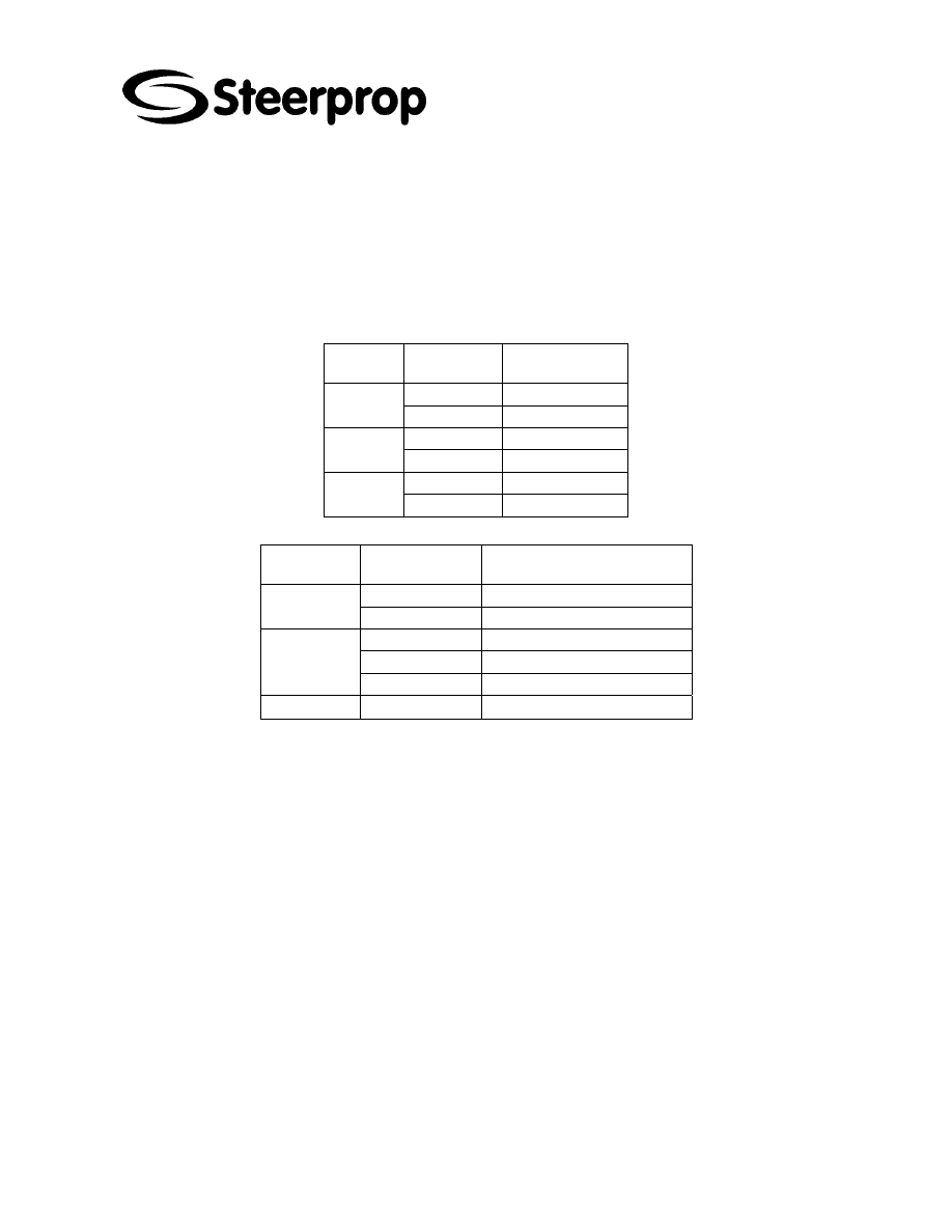
3.2 S
CREW FASTENERS
To ensure a safe operation and a long service of fastening elements, the screw
fastenings should be only torqued. The table below lists the torque figures for used
screws. Through influence of various factors, the specified values may show a
deviation which in individual cases require lower or higher values.
Connection shell/bonnet
type screw/
strength
torque [Nm]
K12 M12
5.6 38
M12
8.8
80
K20 M16
5.6 95
M16
8.8
200
K25 M20
5.6 180
M20
8.8
400
Connection flanges
screw/
strength
material of
thread
torque [Nm]
aluminium 30
M12 5.6
red bronze
30
aluminium 75
red bronze
75
M16 5.6
caststeel 100
M24 5.6
caststeel
300
3.3 T
YPE PLATE
The type plate is at the side of the device and is permanently fixed.

C102959-0 Page 8 of 15
02.04.2008
© The information contained in this document is the sole property of Steerprop Ltd. any reproduction or disclosure in part or whole without written permission is prohibited.
DOC-1017-1
4 S
TART
-
UP
4.1 S
TARTING UP
At first the apparatus must be filled up with the intended medium, then the entire
system must be checked for leakage. For water cooled devices use only clean water at
the tube side. Before the actual starting up of the system, make sure that the cooling
medium is circulated.
Operating the device without flow of cooling medium is not permissible.
Only for water cooled units:
If the flow adjustment is carried out by a control, we recommend a oil-sided control,
especially when operating with river or sea water.
Discuss the control of cooling water with our factory, because factors Iike materia) and
quality of cooling water are very important to avoid later problems.
The use of additives in the cooling water has to be confirmed through HS-Cooler
GmbH.
4.2 O
PERATING INSTRUCTIONS
During the operation, make sure by suitable means that pre-set parameters for which
the devices are designed are kept.
If reserve devices with switchover valves are present, switch these devices periodically
on (all 2-3 days) or load the reserve device daily for some time with the full water
volume.
4.3 S
WITCHING OFF
/
STANDSTILL OF THE UNIT FOR WATER COOLED
UNITS
With a short-term standstill (<4 days) of the unit, the apparatus can remain filled.
When switching off the unit, the water must be removed. In the case of operating the
device with sea water or aggressive water, flush the unit additionally with clean water.
The tube bundle should as far as possible be dried inside with compressed air. Further,
if a drainage is not possible, then a flow of the correct amount of cooling water must be
maintained.

C102959-0 Page 9 of 15
02.04.2008
© The information contained in this document is the sole property of Steerprop Ltd. any reproduction or disclosure in part or whole without written permission is prohibited.
DOC-1017-1
5 M
AINTENANCE
5.1 O
IL TEMPERATURE AT COOLER
The lubrication oil heat exchanger is equipped with temperature gauges ion each end.
Oil input line has the gauge TG2
Oil output line has the gauge TG3
5.2 P
ERIODIC INSPECTIONS
Devices of product Iine K are normally reliable and easy to maintain. However, some
periodic inspections of the device are necessary to provide a safe, continuous
operation. Normally inspections on the tubeside (waterside) predominate. The shellside
is less inclined to pollution so that an inspection can be carried out based on the
experience of the operator.
The following inspections should be practiced:
When operating with sea water, sacrificial anodes are installed in the bonnets/covers.
These should be checked in the initial phase all 3 months. If the anodes are used up,
they must be reached by new ones. In the case of excessively fast consumption of the
anodes, water quality and the electrical potential of the system must be checked.
The device should be cleaned at the water side at least once a year. An excessive
pollution of the tubes must by all means be avoided. The bonnets can be removed
without depressurerizing the shell side. The intervals are to be shortened during Iong
ship operation in harbors or in other polluted waters and depending on the experience
of the operator.
At shorter intervals the device must be subject to an externally visual inspection, in
order to identify leakage or other problems early. Through the double 0-ring sealing,
leakages can be precisely located and the relevant expenditure can be estimated.
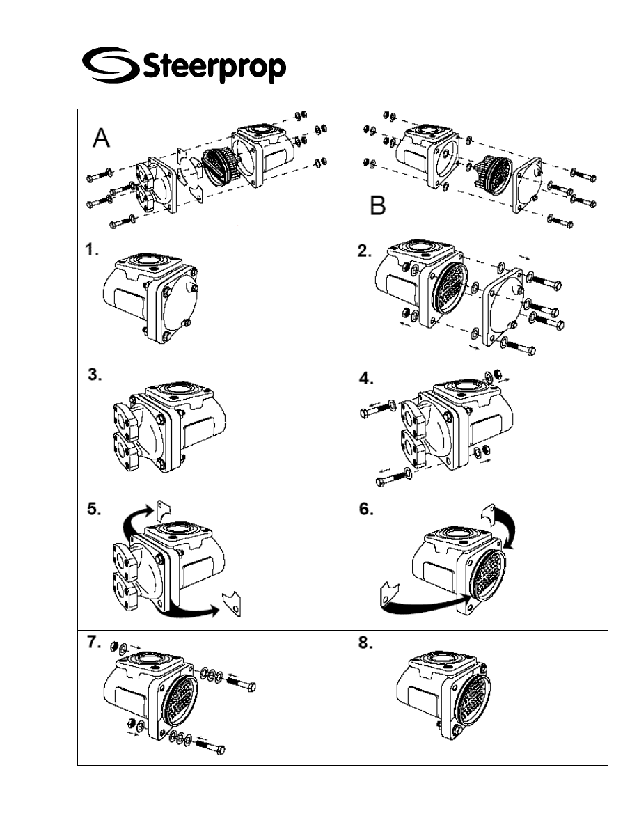
5.3 D
ISMOUNTING
Proceed as follows when dismounting the apparatus:
Lock-up any pipelines
Empty the apparatus at the tube side, if a removal of the tube bundle is
necessary, empty also the shell side.
Remove the pipelines at the tube side.
Remove the bonnets/covers. For this purpose, the screws at the
bonnet/casing connection must be loosened. Between the bonnet/cover
there are 4 fixing plates or washers. These must be replaced at the same
side again during re-assembly. The marking on the casing flange must be
here observed.
If you want to dismount without remove the tube bundle, the bonnet cover
without fixing plates must be disassembled first in order to protect the tube
bundle against displacement, before you remove the fixing plates. This can
be done with another set of fixing plates or with similar aids.

C102959-0 Page 10 of 15
02.04.2008
© The information contained in this document is the sole property of Steerprop Ltd. any reproduction or disclosure in part or whole without written permission is prohibited.
DOC-1017-1
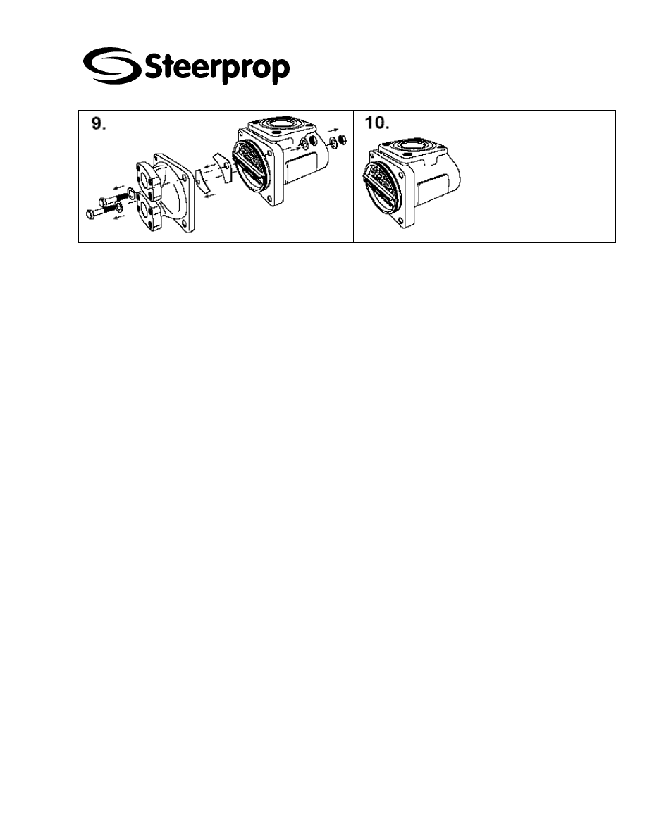
5.3.1 D
ISMOUNTING WITHOUT REMOVE THE TUBE BUNDLE
:
Remove the 0-rings from the external groove of the tube plates and secure
the tube bundle to the casing with four screws and the four fixing plates in
the middle groove of the tube plates. The tube side can now be inspected
and cleaned mechanically. The shell side can remain under pressure.
During assembly the fixing plates have to be assembled to the correct side of the heat
exchanger.
5.3.2 D
ISMOUNTING WITH REMOVE THE TUBE BUNDLE
:
Remove the O-rings from the external groove of the tube plates. At one tube plate, a
marking of the fixed position in relation to the casing is attached. A half of a 'X' is
stamped at the front of the tube plate and the adjacent casing flange. Check the
position of the marking. Push the tube bundle (where appropriate with auxiliary tools)
so far sideways until the 0-ring of the interior groove becomes visible. Remove the 0-
ring from the interior groove. Pull out the tube bundle in the opposite direction. Remove
the tube bundle carefully from the casing without damaging the fins. As far as possible
suspend the tube bundle with the help of large-surface transportation straps. The
grooves taking the 0-rings must not be damaged. During dismounting of the tube
bundle the sealing plate and the spring can drop out of the baffle groove. The spring
and the sealing plate have to be installed during assembly of the bundle by pressing
them into the groove hilst the baffle passes the inlet of the shell.
When dismounting vertically fixed devices, make sure in any case that the tube bundle
does not slips down after removal of the fixing plates. We recommend to provide an
additional set of fixing plates and to start the removal at the side where no fixing plates
are mounted. There the bundle must be secured first. After dismounting the second
bonnet, the bundle can be removed carefully. While assembling, only one set of fixing
plates is permitted at the side of the marking.
5.4 A
SSEMBLY
The assembly is carried out in reversed order as dismounting. The following must also
be considered:
Generally use new 0-rings and clean 0-ring grooves.
Note the marking for proper assembly of the tube bundle (X).
Note the marking for correct assembly of the fixing plates (F).
At the side of the tube bundle there are sealing straps. These should only
be replaced when damaged. When pushing-in the tube bundle take care
that the sealing straps are not displaced or twisted. Before assembling the
tube bundle, the sealing straps should be greased. You can use the
operating medium. The sealing straps must be effective along the entire
length of the tube bundle.
Insert the sealing plate and the spring into the baffle groove and press
down during insertion of the tube bundle
Lubricate 0-rings with suitable 0-ring grease.
During insertion of the tube plate into the sealing faces, make sure that the
0-rings do not shear. The bonnets/covers must be set up in parallel onto the
tube plate and must be pushed evenly onto the 0-ring; ensure also that the
0-ring does not shear.
With two path devices, a path partition must be fitted at the side of the
bonnet with the two connections. At this side, the fixing sheets must also be
installed later.

C102959-0 Page 11 of 15
02.04.2008
© The information contained in this document is the sole property of Steerprop Ltd. any reproduction or disclosure in part or whole without written permission is prohibited.
DOC-1017-1
When assembling the two path bonnet, make sure that the path partition is
correctly placed.
Then continue as described under 'Operation'.
5.5 C
LEANING
In the case of only small amount of fouling, the tube side can be mechanically cleaned.
Disassemble the device as described under 'dismounting without remove the tube
bundle' and clean with a suitable nylon brush (do not use metal brushes) each tube
inside, then clean with water. Never remove stuck deposits or coarse dirt by force.
In the case of stuck deposits, the tube bundle must be cleaned chemically. This can be
carried out by rinsing the tube in the assembled state or submerging in disassembled
state. Such a cleaning must only be practiced by specialists. Only suitable solvents
must be used. To select a suitable agent, refer to the added part list. Take the
materials of the plastic separator strip and 0-rings in the assembled state into
consideration. Under 'Contacts' you find some companies offering respective agents or
carrying out a complete cleaning.
Provided that the type designation gets a C at the 11th position (example: KS12-BCN-
8210 L1000), then it is a coated tube bundle. To prevent a damage caused by
corrosion this bundle is coated on the inside of the tubes and on the tube sheets. When
dismounting the bundle and during cleaning make sure that the coating will not be
damaged or destroyed. Use only nylon cleaning brushes and approved cleaning
agents. If there are any doubts about suitability of an agent, please contact our service
department.
C102959-0 Page 12 of 15
02.04.2008
© The information contained in this document is the sole property of Steerprop Ltd. any reproduction or disclosure in part or whole without written permission is prohibited.
DOC-1017-1
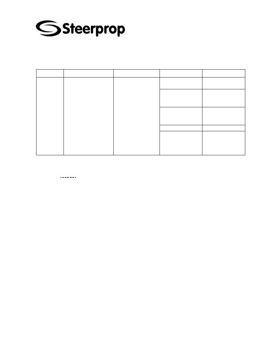
6 C
OOLING SYSTEM FAULT FINDING
FAULT EFFECT
TEMPORARY
ACTION
CAUSE
REMEDY
Cooler is blocked
partly or totally
Clean cooler
There is not enough
water at cooling
circuit
Add water to cooling
circuit
Water circulation
pump is not running
Check, that water
circulation pump is
running and start it
Water leakage
Tighten connectors
Cooler is
not working
Propulsor cooling
capacity is limited. Due
overheating, are
bearings, seals and
gears are in danger to
damage.
Adjust propulsor load
lower and follow the
propulsor oil
temperature and keep
it below alarm limit.
Cooling water
temperature too
high
Measure cooler
input and output
water temperature,
lower temperature
6.1 P
ERFORMANCE TOO LOW
b
C
HECK
:
whether all connections have been made according to the drawing
whether the heat exchanger and the system have been properly vented
whether the flows are according to the specification (check all valves, lines
and pumps, as well as the flow directions)
whether the shell- as well as the tubeside have been cleaned recently
(fouling can cause a drop in performance and an increased pressure loss;
an increased pressure drop is a good indication that cleaning is necessary)
whether the heat exchanger has been reassembled properly after
disassembly (the plastic partitions on the tube sheet(s) of 2- or 3-pass heat
exchangers; the position of the tube bundle (this might accidentally be
mounted rotated 180° around its axis))
Are foreign bodies in pipe or in device causing obstruction?
Are the path partition and the fixing plates correctly assembled in the two
path bonnet?
Are all pressure rooms vented?
Are tube side or shell side too dirty (too thick deposits)?
Are tuore than 10% of the tubes plugged?

C102959-0 Page 13 of 15
02.04.2008
© The information contained in this document is the sole property of Steerprop Ltd. any reproduction or disclosure in part or whole without written permission is prohibited.
DOC-1017-1
6.2 L
EAKY TUBES
!
If the presumption exists that tubes have become leaky, proceed as with 'dismounting
without remove the tube bundle'. The shell side can remain under pressure. After
cleaning the tube plates, you can identify the defective tube by the state of the
emerging medium. Lock the leaky tube at both ends with our 'Tubelock'-Repairset.
Alternative you can use a conical copper or aluminium plug or a conical hard wood
plug. The plug must not be pushed too strong since otherwise adjacent rolling
connections can be damaged. You can lock 10% of the tubes at the most without
noticeable reduction in performance. Dismounting the defective tube is not possible.
6.3 L
EAKY ROLLING CONNECTION
!
If it is found during the check for leaky tubes that a rolling connection is leaky, it can be
rolled again with a specific rolling tool. This work however is only to be carried out by
specially trained personnel. Since defects of this type are uncommon, a check of the
complete bundle in our factory is recommended.
6.4 L
EAKY
0-
RING
!
If a leakage is found between bonnet cover and casing, an 0-ring of the tube plate is
defective. The kind of the emerging medium defines at which groove of the tube plate
the defect developed. In the case of a defect on the tube side, proceed as described
under 'dismounting without remove the tube bundle'. In the case of a defect at the shell
side, proceed as described under 'dismounting with withdrawing the tube bundle'. In
this case the tube bundle does not need to be removed completely from the casing.
Assemble the 0-ring as described in 'Assembly'.
6.5 C
ONTACTS
6.5.1 C
LEANING
Suppliers for cleaning agents:
Ashland Chemicals –
www.ashchem.com
Henkel Oberflächentechnik-
www.henkel.com
Ondeo Nalco —
www.ondeo-nalco.com
Contractors for complete cleaning
Vecom —
www.vecom.nl
- Ondeo Nalco —
www.ondeo-nalco.com
6.6 R
EPAIR
/
SPARE PARTS
Repairs must only be carried out by specially trained personnel. However we
recommend to carry out any repair in our factory.
You can purchase spare parts directly from us with indicating the sketch and serial
number. Please contact our head offices or our sales office.
C102959-0 Page 14 of 15
02.04.2008
© The information contained in this document is the sole property of Steerprop Ltd. any reproduction or disclosure in part or whole without written permission is prohibited.
DOC-1017-1
C102959-0 Page 15 of 15
02.04.2008
© The information contained in this document is the sole property of Steerprop Ltd. any reproduction or disclosure in part or whole without written permission is prohibited.
DOC-1017-1
Wyszukiwarka
Podobne podstrony:
C102954 0 SERVICE SED INSTRUCTIONS
C102951 0 SERVICE NUMBERING
C102953 0 SERVICE USER INSTR
C102957 0 SERVICE POWER TRANSMISSION
C102954 0 SERVICE SED INSTRUCTIONS
general cooling system servicing
Prezentacja firmy MARSTATE SERVICE BHP PPOZ PPT
hplj 5p 6p service manual vhnlwmi5rxab6ao6bivsrdhllvztpnnomgxi2ma vhnlwmi5rxab6ao6bivsrdhllvztpnnomg
PAT DS 350 Graphic Modular GM Service Data
Oberheim Prommer Service Manual
Funai Hita9801 Service Note
03 Service Specifications
Korg SQ 10 Service Manual
więcej podobnych podstron