
C102951-0 Page 1 of 6
07.04.2008
© The information contained in this document is the sole property of Steerprop Ltd. any reproduction or disclosure in part or whole without written permission is prohibited.
DOC-1017-1
Steerprop Propulsor
Numbering,
Identification, Signal
Directions
Service Manual
Revision history:
REV. DATE MODIFIER DESCRIPTION
0 2.4.2008
AaNi Created
A
B
C
D
E
F

C102951-0 Page 2 of 6
07.04.2008
© The information contained in this document is the sole property of Steerprop Ltd. any reproduction or disclosure in part or whole without written permission is prohibited.
DOC-1017-1
1
CODES AND ABBREVIATIONS USED IN THIS MANUAL .......................................................... 3
2
PROPULSOR NUMBERING ............................................................................................................... 4
2.1
C
ONTROL UNITS NUMBERING
........................................................................................................... 4
3
CONTROL STATION NUMBERING ................................................................................................. 5
3.1
C
ONTROL STATION NUMBERING
...................................................................................................... 5
3.2
C
ONTROL PANEL
WCP
NUMBERING
................................................................................................ 5
3.3
W
ING TYPE CONTROL PANEL
WSP
NUMBERING
.............................................................................. 5
4
SIGNAL DIRECTIONS......................................................................................................................... 6

C102951-0 Page 3 of 6
07.04.2008
© The information contained in this document is the sole property of Steerprop Ltd. any reproduction or disclosure in part or whole without written permission is prohibited.
DOC-1017-1
1 C
ODES AND ABBREVIATIONS USED IN THIS MANUAL
CODE DESCRIPTION
CODE
DESCRIPTION
ACU
AC/DC Converter Unit
SAI
Steerprop Angle Indicator
AIU
Alarm Indication Unit
SAP Steerprop Azimuth Propulsor
ALARM Alarm system
SCB Steerprop Propulsor Connection Box
AP
Autopilot
SCL
Steerprop Control Lever
APC
Autopilot Command Unit
SCU Steerprop Control Unit
APD
Autopilot Distribution Unit
SJC
Steerprop Joystick Computer
BCP
Back-up Control Panel
SJD
Steerprop Joystick Display
BFU
Brake and Fan Control Unit
SJP
Steerprop Joystick Panel
TGA
Control System Block Diagram SOT Seal Oil Tank
BRU
Brake Resistor Unit
SRI
Steerprop Rpm Indicator
BT
Bow Thruster
STB
SOT Connection Box
CPU
Clutch Pump Unit
STU Steerprop Transmitter Unit
CSU Clutch
Pump
Starter
TG Telegraph
DP
Dynamic Positioning Systen
VDR Voyage Data Recorder
ECDIS
Electric map system
WCP Wheelhouse Control Panel
ECP
Engine Control Room Panel
WH
Wheelhouse
ENGINE Diesel motor
WSP Wing Steering Panel
EPSS
Electric Power Supply
Switchboard
ER
Engine Room control
TLU
Turning Gear Lubrication Unit
ESU Electric
Steering
Unit
TPU
Turning Gear Lubrication Pump
GA
General Arrangement Drawing TLA
Turning Gear Lubrication Distribution
GPS
Global Positioning System
SU1
Emergency Lubrication Pump
GYRO Gyrocompass
LG Lower
Gear
HCB
Hydraulic Connection Box
UG
Upper Gear
HPU
Hydraulic Power Unit
SMU Steerprop Motor Control Unit
HSU
Hydraulic Starter Unit
JC Joystick
Control
System
LCR Local
Control
Switch
LLG
Lubrication Lower Gear Unit
LOR
Lubrication Oil Reservoir
LPU
Lubrication Pump Unit
LSU Lubrication
Starter
LUG
Lubrication Upper Gear Unit
MC Mission
Computer
PFU
Pump Motor Fan Control Unit
PM Propeller
Motor
PR Propulsor
Room
C102951-0 Page 4 of 6
07.04.2008
© The information contained in this document is the sole property of Steerprop Ltd. any reproduction or disclosure in part or whole without written permission is prohibited.
DOC-1017-1
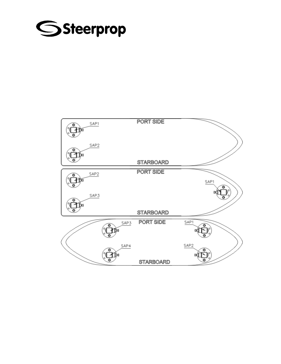
2 P
ROPULSOR NUMBERING
The exact coding in the actual project is shown in the General Arrangement (GA) and
in the control system block diagram.
The propulsor and control unit numbering is always shown at CONTROL SYSTEM
BLOCK DIAGRAM.
Propulsor numbering starts from Bow Port Side and ends to Stern
Starboard
2.1 C
ONTROL UNITS NUMBERING
The numbering follows the numbers of the propulsors
C102951-0 Page 5 of 6
07.04.2008
© The information contained in this document is the sole property of Steerprop Ltd. any reproduction or disclosure in part or whole without written permission is prohibited.
DOC-1017-1
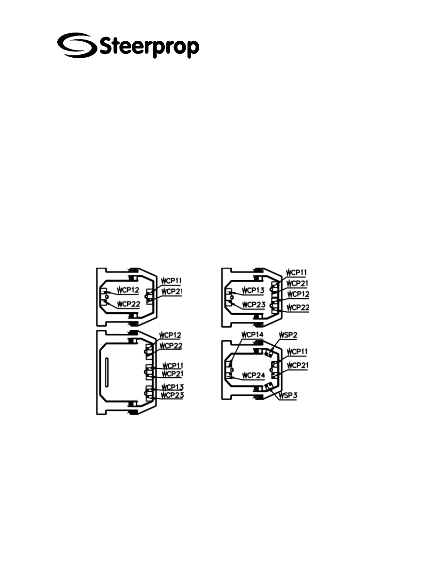
3 C
ONTROL STATION NUMBERING
The exact coding in the actual project is shown in the General Arrangement (GA) and
in the control system block diagram.
3.1 C
ONTROL STATION NUMBERING
Remote control panel numbering starts from Fore Center station and the
next is fore Port Side station.
3.2 C
ONTROL PANEL
WCP
NUMBERING
First number is according propulsor
Second number is according control station
3.3 W
ING TYPE CONTROL PANEL
WSP
NUMBERING
The controls of all propulsor are mounted into same panel.
The number is according control station
C102951-0 Page 6 of 6
07.04.2008
© The information contained in this document is the sole property of Steerprop Ltd. any reproduction or disclosure in part or whole without written permission is prohibited.
DOC-1017-1
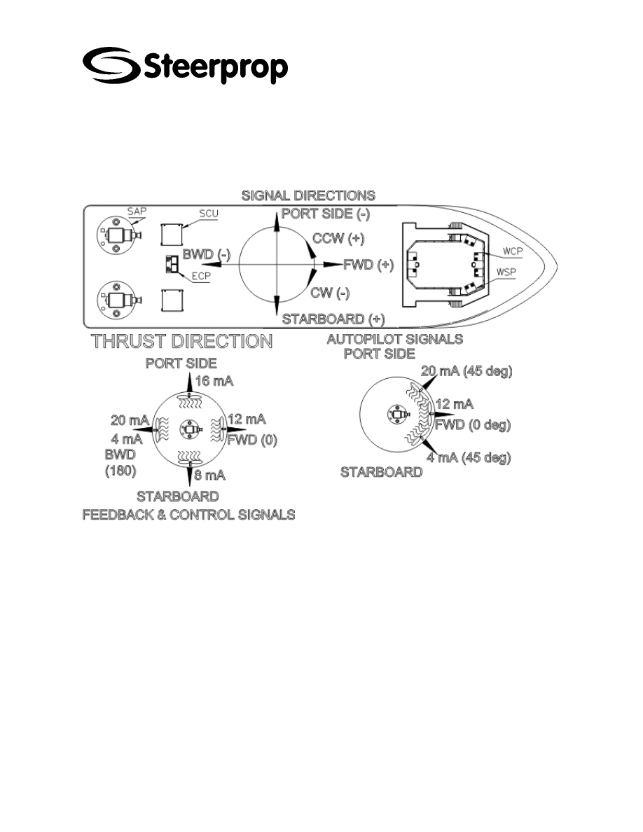
4 S
IGNAL DIRECTIONS
The exact coding in the actual project is shown in the General Arrangement (GA) and
in the control system block diagram.
Wyszukiwarka
Podobne podstrony:
C102954 0 SERVICE SED INSTRUCTIONS
C102959 0 SERVICE COOLING
C102953 0 SERVICE USER INSTR
C102957 0 SERVICE POWER TRANSMISSION
C102954 0 SERVICE SED INSTRUCTIONS
Prezentacja firmy MARSTATE SERVICE BHP PPOZ PPT
hplj 5p 6p service manual vhnlwmi5rxab6ao6bivsrdhllvztpnnomgxi2ma vhnlwmi5rxab6ao6bivsrdhllvztpnnomg
PAT DS 350 Graphic Modular GM Service Data
Oberheim Prommer Service Manual
Funai Hita9801 Service Note
fall leaves cal numbers2
03 Service Specifications
Korg SQ 10 Service Manual
więcej podobnych podstron