
C102954-0 Page 1 of 14
02.04.2008
© The information contained in this document is the sole property of Steerprop Ltd. any reproduction or disclosure in part or whole without written permission is prohibited.
DOC-1017-1
Service Display
Service Instructions
Service Manual
Revision history:
REV. DATE MODIFIER DESCRIPTION
0 2.4.2008
AaNi Created
A
B
C
D
E
F

C102954-0 Page 2 of 14
02.04.2008
© The information contained in this document is the sole property of Steerprop Ltd. any reproduction or disclosure in part or whole without written permission is prohibited.
DOC-1017-1
1
MAINTENANCE.................................................................................................................................... 3
1.1
B
ACKLIGHT
...................................................................................................................................... 3
1.2
B
ATTERY
.......................................................................................................................................... 3
2
INSPECTION AND CLEANING ......................................................................................................... 4
2.1
C
LEANING
M
ETHODS
....................................................................................................................... 4
2.2
I
NSPECTION
M
ETHODS
..................................................................................................................... 5
2.3
I
NSPECTION
I
TEMS
........................................................................................................................... 5
3
REQUESTING A REPLACEMENT PT.............................................................................................. 6
4
TROUBLESHOOTING AND MAINTENANCE ................................................................................ 7
4.1
E
RRORS DURING
D
ATA
T
RANSFER
................................................................................................... 7
4.2
E
RRORS DURING
PT
S
TARTUP
.......................................................................................................... 8
4.3
F
ATAL ERRORS DURING
PT
P
OWERUP
............................................................................................. 9
4.4
E
RRORS DURING
PT
P
OWERUP
........................................................................................................10
4.5
W
ARNINGS DURING
PT
P
OWERUP
...................................................................................................11
4.6
E
RRORS WHILE
C
ONNECTING TO THE
H
OST
...................................................................................12
4.7
E
RRORS DURING
PT
O
PERATION
.....................................................................................................13
4.8
E
RRORS DURING
O
BJECT
O
PERATION
.............................................................................................14
C102954-0 Page 3 of 14
02.04.2008
© The information contained in this document is the sole property of Steerprop Ltd. any reproduction or disclosure in part or whole without written permission is prohibited.
DOC-1017-1
1 M
AINTENANCE
1.1 B
ACKLIGHT
After 50,000 hours of use at room temperature and humidity the backlight must be
replaced when the brightness of the display backlight dims and the display becomes
difficult to see. The backlight cannot be replaced by the user. The service life of the
backlight will be especially shortened if used in a low-temperature environment.
Replace the backlight when the brightness dims and the display becomes difficult to
see.
1.2 B
ATTERY
Use a lithium battery to back up data other than screen data, such as calendar, clock,
and log data. The battery service life is approximately five years at 25
°
C. The service
life will be shortened if the battery is used at higher temperatures. Replace the battery
periodically, according to the operating environment. Keep a spare battery available, so
that the battery can be replaced immediately when required.
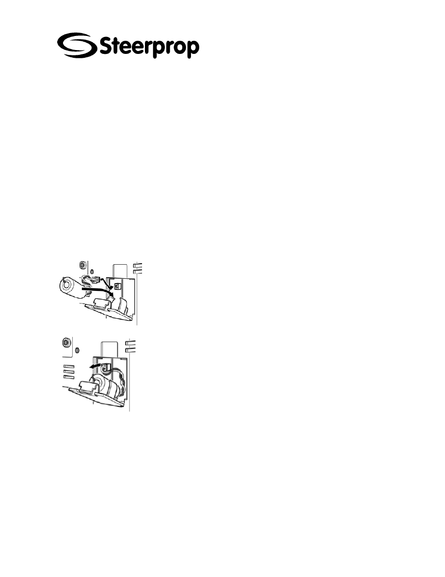
Perform the following procedure within five minutes to replace the battery.
The shape of the battery cover and the direction for installing the connector
depend on the PT model.
1. After power to the PT has been turned ON and at least five minutes have
lapsed, turn OFF the power.
2. Open the battery cover on the rear panel of the PT.
3. Remove the battery that is secured inside the PT, grasp the cable, and pull
the connector out vertically to remove it.
4. Connect the new battery connector, and insert the battery into the battery
holder in the battery cover.
5. Close the battery cover, being careful not to squash the battery cable.

C102954-0 Page 4 of 14
02.04.2008
© The information contained in this document is the sole property of Steerprop Ltd. any reproduction or disclosure in part or whole without written permission is prohibited.
DOC-1017-1
2 I
NSPECTION AND CLEANING
Clean and inspect the PT periodically to maintain it in optimum condition for use.
2.1 C
LEANING
M
ETHODS
The screen visibility will be impaired if the display becomes dirty. Clean the display
periodically using the following methods:
For daily cleaning, wipe with a soft, dry cloth. Attempting to remove heavy
dirt with the cloth may scratch the front panel sheet. Use a damp cloth and
wipe the surface again to remove dirt.
If dirt cannot be removed using a dry cloth, dampen the cloth sufficiently
with a neutral cleaning agent solution (approximately 2%), squeeze the
cloth out, and then wipe the surface.
Materials such as rubber, vinyl, or tape that are attached to the Unit will
leave stains if left for a long time. If such material is attached to the Unit,
remove when cleaning.
*
NOTE NEVER USE BENZENE, THINNER, OR OTHER VOLATILE SOLVENTS, OR
CHEMICAL CLOTHS TO CLEAN THE PT.

C102954-0 Page 5 of 14
02.04.2008
© The information contained in this document is the sole property of Steerprop Ltd. any reproduction or disclosure in part or whole without written permission is prohibited.
DOC-1017-1
2.2 I
NSPECTION
M
ETHODS
Inspect the PT once every six to twelve months. Shorten the interval between
inspections when using the PT in extreme conditions, such as under high
temperatures, high humidity, or environments subject to large quantities of dust.
2.3 I
NSPECTION
I
TEMS
Inspect the PT for the following items to check whether the PT is operating within the
speci-fied criteria. If the PT is outside the criteria, use measures such as improving the
operating environment to conform to the standards, or tightening screws.
INSPECTION ITEMS
INSPECTION DETAILS
CRITERIA
INSPECTION MEANS
Power supply
Power terminal voltage fluctuation
Allowable voltage range (24
VDC ±15%)
Tester
Ambient temperature (temperature
in control panel)
0 to 50°C
Thermometer
Ambient humidity (temperature in
control panel)
35% to 85%
Temperature meter
Presence of dust
No dust accumulated.
Visual inspection
Ambient
environment
Presence of oil
No oil between front panel
sheet and molding
Visual inspection
Looseness of fixed mounting
bracket
Specified torque.
Phillips screwdriver
Connection status of Connecting
Cable Connectors
Fully inserted, locked, and
with No looseness.
Phillips screwdriver
Looseness of external wiring
screws
No looseness.
Phillips screwdriver
Mounting conditions
Status of external connecting
cables
No breaks or other damage Visual inspection, tester
Backlight brightness
Sufficient brightness.
Backlight life (at room
temperature of 25°C) is
50,000 hours, as a
guideline.
Visual inspection
Parts with limited
service life
Battery
5 years (at room
temperature of 25°C).
Replace every 5 years
*
DO NOT DISASSEMBLE, REPAIR, OR MODIFY THE PT. FOLLOW ALL LOCAL
GOVERNMENT REGULATIONS, WHERE APPLICABLE, WHEN DISPOSING OF THE
UNIT AND USED BATTERIES.

C102954-0 Page 6 of 14
02.04.2008
© The information contained in this document is the sole property of Steerprop Ltd. any reproduction or disclosure in part or whole without written permission is prohibited.
DOC-1017-1
3 R
EQUESTING A
R
EPLACEMENT
PT
Always observe the following precautions when faults are detected during inspection
and the PT is to be replaced.
Create a backup of the PT project data. Project data may be deleted when
the PT is repaired by OMRON.
Always turn OFF the power before replacing the PT.
After replacing the PT, check to confirm that the new PT has no faults.
When returning a faulty PT for repair, include a document with the Unit that
provides as many details on the fault as possible, and send to your
OMRON representative.

C102954-0 Page 7 of 14
02.04.2008
© The information contained in this document is the sole property of Steerprop Ltd. any reproduction or disclosure in part or whole without written permission is prohibited.
DOC-1017-1
4 T
ROUBLESHOOTING AND MAINTENANCE
When an error occurs while operating the PT, search for the symptom in the following table and take
measures according to those provided.
4.1 E
RRORS DURING
D
ATA
T
RANSFER
SYMPTOMS AT PT
CAUSES
MEASURES
The NS-Designer is not connected to
the PT.
Check the wiring conditions of the
connecting cable.
Serial transfer not possible between
NS-Designer and PT.
The Expansion Interface for serial port
B is set to the expansion interface
Set the Expansion Interface to
Disable on the Comm Tab Page from
the NS5 System Menu.
The installed PT system is using
system program lower than Ver. 6.2.
Install system program Ver. 6.2 or
higher in the PT.
The PT has a lot number earlier than
that indicated in 3-3-2 Connecting via
USB.
Use a PT from the lot number (or
later) indicated in 3-3-2 Connecting
via USB.
The USB cable is longer than 2 m.
To use a cable longer than 2 m,
connect a USB Hub between the PT
and personal computer as shown in
Connection Methods under in 3-3-2
Connecting via USB.
Personal computer cannot detect PT
when connected via USB.
A malfunction has occurred due to
external noise.
Configure the USB Hub and wire the
USB cables taking measures to
prevent noise.
The USB cable is longer than 2 m.
To use a cable longer than 2 m,
connect a USB Hub between the PT
and personal computer as shown in
Connection Methods under in 3-3-2
Connecting via USB.
Timeout occurs during screen transfer
using USB.
A malfunction has occurred due to
external noise.
Configure the USB Hub and wire the
USB cables taking measures to
prevent noise.

C102954-0 Page 8 of 14
02.04.2008
© The information contained in this document is the sole property of Steerprop Ltd. any reproduction or disclosure in part or whole without written permission is prohibited.
DOC-1017-1
4.2 E
RRORS DURING
PT
S
TARTUP
SYMPTOMS AT PT
CAUSES
MEASURES
Power is not being supplied to the PT
Check the connection points and supply
power to the PT correctly.
The fuse is broken.
The PT needs repair. Contact your
nearest OMRON representative.
Indicators do not light
The system pro-gram is corrupted (fatal
error).
The PT may be faulty. Contact your
nearest OMRON representative
The indicator is lit orange
and the screen is blank
The system pro-gram is corrupted (fatal
error).
The PT may be faulty. Contact your
nearest OMRON representative.
The indicator is lit green
and the screen is blank.
The system pro-gram is corrupted (non-fatal
error). The combination of NS-series PT
hardware and sys-tem program version is
incorrect.
Recovery/update the system program.
Contact your nearest OMRON
representative if the same problem occurs
after recovering/updating the system pro-
gram.
The indicator is flashing
green and the buzzer re-
peatedly turns ON and
OFF.
The backlight has malfunctioned.
The backlight must be replaced. Contact
your nearest
OMRON representative.
The screen is blank and the
indicator is flashing green.
Automatic up-load/download has ended
normally.
This is not an error. Turn OFF all the DIP
switch pins and turn ON the power to the
PT again.
The screen is blank and the
indicator is flashing red.
Automatic up-load/download has ended
abnormally.
The system program may be corrupted.
Reinstall the sys-tem program.
(Refer to 3-6 Using Memory Cards.)
If the same problem occurs after
reinstalling the system program, the PT
may be faulty. Contact your nearest
OMRON representative.
An attempt may have been made to
transfer screens that are larger than the
memory of the PT. Check the screen data
at the transfer destination.
The indicator is lit red and
the screen is blank.
The PT is faulty, or the system pro-gram is
corrupted.
Reinstall the system program. (Refer to 3-
6 Using Memory Cards.)
If the same problem occurs after
reinstalling the system program, the PT
may be faulty. Contact your nearest
OMRON representative.

C102954-0 Page 9 of 14
02.04.2008
© The information contained in this document is the sole property of Steerprop Ltd. any reproduction or disclosure in part or whole without written permission is prohibited.
DOC-1017-1
4.3 F
ATAL ERRORS DURING
PT
P
OWERUP
MESSAGE CAUSES
POSSIBLE
COUNTERMEASURE
FATAL ERROR No. 01: Touch Panel is not
connected: Please contact your OMRON
service center.
Touch panel error.
FATAL ERROR No. 02: SRAM Initialization
Error: Please contact your OMRON service
center.
Hardware error in log SRAM.
FATAL ERROR No. 03: MAC Address
Error: Please contact your OMRON ser-
vice center.
Incorrect MAC address
FATAL ERROR No. 04: PT Model type
Identify Error: Please contact your OMRON
service center
Built-in model code cannot be read
Contact your nearest OMRON
representative.

C102954-0 Page 10 of 14
02.04.2008
© The information contained in this document is the sole property of Steerprop Ltd. any reproduction or disclosure in part or whole without written permission is prohibited.
DOC-1017-1
4.4 E
RRORS DURING
PT
P
OWERUP
MESSAGE CAUSES
POSSIBLE
COUNTERMEASURE
ERROR No. 10: File System Error: Please
recover the system program.
File system is corrupted. (A
hardware fault occurred or power
was interrupted during writing.)
ERROR No. 10: Fail in loading files or
executing pro-gram: Please recover the
system program.
File reading or program execution
failed.
ERROR No. 10: Fail in loading files: Please
recover the system program.
File reading failed.
Reinstall the system program by
inserting the Memory Card con-
taining the recovery program in the
PT and resetting the PT or turning
the power supply OFF and ON
again. If the same problem occurs
after reinstalling the sys-tem
program, contact your near-est
OMRON representative.
ERROR No. 11: Fail in loading files: Please
reinstall the system program.
File reading failed.
ERROR No. 11: Device check program
error: Please reinstall the system pro-gram.
Hardware check program is
corrupted.
ERROR No. 11: SRAM check program
error: Please reinstall the system pro-gram.
Log SRAM check program is
corrupted.
ERROR No. 11: IP Address Setting Error:
Please rein-stall the system program.
IP address setting program is
corrupted.
Execute automatic download of the
system program. If the same
problem occurs after downloading,
insert the Memory Card containing
the recovery program in the PT and
reset the PT or turn the power
supply OFF and ON again If the
same problem occurs after
reinstalling the system program,
contact your nearest OMRON
representative.
ERROR No. 11: Device check program
error: Touch the screen to continue.
At startup with DIP switch 6 set to
ON, the hardware check pro-gram
is corrupted.
The Memory Card transfer pro-
gram started up after this can be
used. If operation is not restored
after continuing with the Memory
Card transfer program, insert the
Memory Card containing the
recovery program in the PT and
reset the PT or turn the power
supply OFF and ON again If the
same problem occurs after
reinstalling the system program,
contact your nearest OMRON
representative.
ERROR No. 12: Fail in loading fonts:
Please reinstall the system program.
Reading of font files when
operation performed with DIP
switch 6 set to ON failed.
ERROR No. 12: Installed system program
is not applicable for this hardware: Please
reinstall the system program.
The installed system program does
not match the hardware.
Download the system program by
automatic download that does not
use DIP switch 6. If operation is not
restored after downloading, insert
the Memory Card containing the
recovery system program in BANK
1 in the PT. If the same problem
occurs after reinstalling the system
program, contact your nearest
OMRON representative.

C102954-0 Page 11 of 14
02.04.2008
© The information contained in this document is the sole property of Steerprop Ltd. any reproduction or disclosure in part or whole without written permission is prohibited.
DOC-1017-1
4.5 W
ARNINGS DURING
PT
P
OWERUP
MESSAGE CAUSES
POSSIBLE
COUNTERMEASURE
WARNING No. 20: Date and Time are not
set: Touch the screen to continue.
Date set outside the PT’s allow-
able range of 2000 to 2049.
Touch the touch panel to continue
booting. Then set the correct date
in the System Menu.
WARNING No. 21: SRAM previously
broken. Initialization Complete: Touch the
screen to continue.
SRAM contents could not be held
because the battery was not
connected or there was in-sufficient
capacity. For this rea-son, SRAM
was initialized.
Touch the touch panel to con-tinue
booting. Replace the bat-tery the
next time power is turned OFF.
WARNING No. 22: Memory Card Error:
Some files in a memory card may be cor-
rupted. Safely remove the memory card,
and check whether files are not cor-rupted
on a computer. You can continue to startup
the PT by touching on the screen, however,
it may NOT operate correctly when
accessing to the memory card. (The same
message will also be displayed in
Japanese. This is not a fault.)
The two following causes are
possible:
The previous time the PT was
used, power was turned OFF while
accessing the Memory Card.
Memory Card access safety
information could not be held
because the battery was con-
nected or there was insufficient
capacity.
Touch the touch panel to con-tinue
booting. When the Memory Card is
accessed, however, the PT may not
operate normally.
WARNING No. 23: Screen data file(s) is
not correct: Touch the screen to con-tinue
and transfer screen data again.
The PT screen data is corrupted.
(The cable was disconnected or
the power was turned OFF during
screen data transfer).
Touch the PT’s touch panel, and
after connecting is displayed at the
bottom right of the screen, or after
the message "No project data is
registered. Press OK but-ton and
download project data." is
displayed, reattempt screen
transfer.

C102954-0 Page 12 of 14
02.04.2008
© The information contained in this document is the sole property of Steerprop Ltd. any reproduction or disclosure in part or whole without written permission is prohibited.
DOC-1017-1
4.6 E
RRORS WHILE
C
ONNECTING TO THE
H
OST
SYMPTOMS AT PT
CAUSES
MEASURES
The settings for Ethernet connection,
such as node number, network
number, and IP address, are not set
correctly.
Set the settings correctly, referring to
Section 5 Connecting to Host via
Ethernet or Controller Link.
The protocol settings for the host and
the settings at the PT do not match.
Set the communications settings
using the CX-Designer.
The PT is not connected to the host
properly.
Check that the type, length, and
wiring of the connecting cables meet
the specifications.
(Refer to Section 4 Connecting the
Host to Serial Port.)
For 1:N NT Link connections, two or
more Units have the same unit
number.
Reset so that each Unit has a unique
unit number.
(Refer to 6-6 Communications
Settings.)
PT cannot communicate with the host.
(An error message is displayed or
connecting is displayed at the bottom
right of the screen.)
With the NS5, the Expansion Interface
for serial port B is set to the
expansion inter-face when the
connection is to serial port B.
Set the Expansion Interface to
Disable on the Comm Tab Page from
the NS5 System Menu.

C102954-0 Page 13 of 14
02.04.2008
© The information contained in this document is the sole property of Steerprop Ltd. any reproduction or disclosure in part or whole without written permission is prohibited.
DOC-1017-1
4.7 E
RRORS DURING
PT
O
PERATION
SYMPTOMS AT PT
CAUSES
MEASURES
Power is not being supplied to the
PT.
Check the connection points and supply power to
the PT correctly.
RUN indicator does not
light.
The fuse is broken.
Contact your nearest OMRON representative.
The PT is in system startup waiting
status.
This is not an error. Information will be displayed
when the waiting time has lapsed.
The screen saver function is
operating.
This is not an error. Touch the screen, or operate
the sys-tem memory for switching the screen from
the host to switch the screen as follows:
Set the screen number in $SW0.
Set the pop-up screen number in $SW1, 4 and 7.
The backlight is OFF.
Turn ON the backlight by setting system memory
bits $SB6 to 8 for adjusting backlight brightness to
ON.
The screen is blank.
The backlight has malfunctioned.
The backlight must be replaced. Contact your
nearest OMRON representative.
Screen switching, opening and
closing pop-up screens, and
switching frames are being
performed frequently.
If screens are opened and closed frequently, the
display update may take some time and
communications may be delayed.
Adjust the interval between screen switches so that
the system is not overloaded.
The display update is slow
The message communications
interval is too long.
On the NS-Designer, select Settings - System
Setting, click the Comm-All Tab, press the Comm.
Details Button, and set a shorted communications
interval.
PT has malfunctioned due to
external noise.
Reset the PT, and wire it according to noise
prevention measures.
The touch panel does not
respond.
The touch panel is damaged.
Test the touch panel using the hardware check in
the Sys-tem Menu. If an error has occurred, contact
your nearest OMRON representative.
The brightness set-ting is too low.
Increase the backlight brightness in the PT Tab
Page of the System Menu.
The display is dark.
The backlight is faulty or its service
life has expired.
The backlight must be replaced. Contact your
nearest OMRON representative.
The communications settings are
incorrect.
When using the device monitor, set the
communications mode as follows:
C-series PLCs: 1:1 NT Link or 1:N NT Links
CS1-series PLCs: 1:N NT Links (normal, high
speed)
The device monitor function is not supported for
Ethernet or Controller Link.
Cannot enter the device
monitor function.
The PLC does not support the
device monitor function.
The PLCs that support the device monitor function
are restricted. Check the PLC model being used.

C102954-0 Page 14 of 14
02.04.2008
© The information contained in this document is the sole property of Steerprop Ltd. any reproduction or disclosure in part or whole without written permission is prohibited.
DOC-1017-1
4.8 E
RRORS DURING
O
BJECT
O
PERATION
SYMPTOMS AT PT
CAUSES
MEASURES
Communications are unstable due
to external noise.
Perform noise countermeasures such as
separating communications cables from power
lines.
There are too many Numeral
Display & Input objects and String
Display & Input objects in the
display.
Reduce the number of Numeral Display & Input
and String Display & Input objects in the screen
where update is slow.
For RS-422A communications, the
branch is incorrect or the
terminating resistance is not set
properly.
Wire correctly
The host is processing a large
volume of data and the cycle time
is long.
Shorten the host cycle time.
The numerical and
character string update is
slow.
The message communications
interval is too long.
On the NS-Designer, select Settings - System
Setting, click the Comm-All Tab, press the Comm.
Details Button, and set a shorted communications
interval.
Some objects in the screen
configuration are not
displayed.
A communications error has
occurred.
Check the communications settings again.
Some objects in the screen
configuration are not
displayed.
The control flags set in the object
include Hide Display Flags.
Display the control flags for the objects set to be
not displayed, as follows: Display the Expansion
Tab from the functional object property setting
using the NS-Designer. Select Display from
Display/Hide in the Control Flags Tab Page. Turn
ON the indirect address of the control flag set for
the object.
The Log Flag display does
not match the actual log
timing.
The communications address set
for the event of log timing is turning
ON and OFF at high speed.
Set the ON/OFF cycle of the communications
address for events to a longer time.
Cannot input numerical
values.
The numerical value input upper
and lower limit check function is
running.
Display the Expansion Tab from the functional
object property setting using the NS-Designer.
Check the set values in the Input Upper and Lower
Limits Tab Page and correct if necessary.
The control flags set in the objects
include Input Prohibit Flags.
Display the Expansion Tab from the functional
object property settings using the NS-Designer.
Select Enable for Input in the Control Flag Tab
Page. Turn ON the indirect address of the control
flag set for the object.
Cannot input for some
functional objects.
A password has been set.
Input the password in the password input dialog
box that is displayed.
Wyszukiwarka
Podobne podstrony:
C102959 0 SERVICE COOLING
C102951 0 SERVICE NUMBERING
C102953 0 SERVICE USER INSTR
C102957 0 SERVICE POWER TRANSMISSION
Instrukcja obsługi AL-700, Instrukcje serwisowe Service manual
SERVICE INSTRUCTION TV HYUNDAI H TV2110SPF
10 4 1 3 Packet Tracer Multiuser Implement Services Instructions
Rieju RS2 KOSO instrukcja obługi licznika elektrycznego manual service
30 Service Manual Installation instructions for coolbox
24 Service Manual Fitting instruction for Airbag Key Switch
wykład 6 instrukcje i informacje zwrotne
Prezentacja firmy MARSTATE SERVICE BHP PPOZ PPT
więcej podobnych podstron