
10/10 MN04802002Z-EN
replaces 08/08 AWB2726-1594GB
User Manual
easy80
0
HMI
Multi-Function Display MFD4
Eaton Corporation
Eaton ist ein führendes Energie-
Management-Unternehmen. Weltweit
ist Eaton mit Produkten, Systemen und
Dienstleistungen in den Bereichen Electrical,
Hydraulics, Aerospace, Truck und
Automotive tätig.
Eatons Electrical Sector
Eatons Electrical Sector ist weltweit führend
bei Produkten, Systemen und Dienstleistungen
zu Energieverteilung, sicherer Stromversorgung
und Automatisierung in der Industrie, in Wohn- und
Zweckbauten, öffentlichen Einrichtungen, bei Energie-
versorgern, im Handel und bei OEMs.
Zu Eatons Electrical Sector gehören
die Marken Cutler-Hammer®, Moeller®,
Micro Innovation, Powerware®, Holec®,
MEM® und Santak®.
www.eaton.com
Eaton Adressen weltweit:
www.moeller.net/address
E-Mail: info-bonn@eaton.com
Internet: www.eaton.com/moellerproducts
www.eaton.comDirecciones de
Eaton en todo el mundo:
www.moeller.net/address
E-Mail: info-bonn@eaton.com
Internet: www.eaton.com/moellerproducts
www.eaton.comIndirizzi EATON
nel mondo:
www.moeller.net/address
4 *patpks#nycmyn*
Rückenbreite 4 – 6 mm (1 Blatt = 0,106 mm für XBS Digitaldruck)
(1 Blatt = 0,080 mm für Eberwein Digitaldruck bei 80 g/m
2
)

All brand and product names are trademarks or registered
trademarks of the owner concerned.
Emergency On Call Service
Please call your local representative:
http://www.eaton.com/moeller/aftersales
or
Hotline After Sales Service:
+49 (0) 180 5 223822 (de, en)
Original Operating Instructions
The German-language edition of this document is the original
operating manual.
Translation of the original operating manual
All editions of this document other than those in German language
are translations of the original German manual.
1
st
edition 2007, edition date 03/07
2
nd
edition 06/07
3
rd
edition 08/08
4
rd
edition 10/10
See revision protocol in the “About this manual“ chapter
© Eaton Industries GmbH, 53105 Bonn
Author:
Norbert Mausolf
Production: Thomas Kracht
Translation: Terence Osborn
All rights reserved, including those of the translation.
No part of this manual may be reproduced in any form
(printed, photocopy, microfilm or any other process) or processed,
duplicated or distributed by means of electronic systems without
written permission of Eaton Industries GmbH, Bonn.
Subject to alteration without notice.
Rü
cken
brei
te
f
e
stl
e
g
e
n! (
1
Bl
att = 0,
10
6 mm,
gi
lt
n
u
r für XBS)

1
Before commencing the installation
• Disconnect the power supply of the device.
• Ensure that devices cannot be accidentally restarted.
• Verify isolation from the supply.
• Earth and short circuit.
• Cover or enclose neighbouring units that are live.
• Follow the engineering instructions (AWA) of the
device concerned.
• Only suitably qualified personnel in accordance with
EN 50110-1/-2 (VDE 0105 Part 100) may work on
this device/system.
• Before installation and before touching the device ensure
that you are free of electrostatic charge.
• The functional earth (FE) must be connected to the protective
earth (PE) or to the potential equalisation. The system installer
is responsible for implementing this connection.
• Connecting cables and signal lines should be installed so
that inductive or capacitive interference does not impair the
automation functions.
• Install automation devices and related operating elements in
such a way that they are well protected against unintentional
operation.
• Suitable safety hardware and software measures should be
implemented for the I/O interface so that a line or wire
breakage on the signal side does not result in undefined
states in the automation devices.
• Ensure a reliable electrical isolation of the low voltage for the
24 volt supply. Only use power supply units complying with
IEC 60364-4-41 (VDE 0100 Part 410) or HD 384.4.41 S2.
• Deviations of the mains voltage from the rated value must
not exceed the tolerance limits given in the specifications,
otherwise this may cause malfunction and dangerous
operation.
• Emergency stop devices complying with IEC/EN 60204-1 must
be effective in all operating modes of the automation devices.
Unlatching the emergency-stop devices must not cause restart.
• Devices that are designed for mounting in housings or control
cabinets must only be operated and controlled after they have
been installed with the housing closed. Desktop or portable
units must only be operated and controlled in enclosed
housings.
• Measures should be taken to ensure the proper restart of
programs interrupted after a voltage dip or failure. This should
not cause dangerous operating states even for a short time.
If necessary, emergency-stop devices should be implemented.
• Wherever faults in the automation system may cause
damage to persons or property, external measures must be
implemented to ensure a safe operating state in the event of
a fault or malfunction (for example, by means of separate limit
switches, mechanical interlocks etc.).
Eat
on Indu
stries GmbH
Safety i
nstru
ctio
ns
Danger!
Dangerous electrical voltage!

2

10/10 MN04802002Z-EN
1
5
7
– Battery 7
– Memory card (MCC)
– Mounting/removing the device
– Ventilation 13
Preventing interference
– Suppressor circuitry for interference sources
– Shielding 13
Lighting protection
– Ethernet 14
– RS232 15
– CANopen/easyNet
– Setting parameters on the display
Changing from application screen n basic menu
20
– Changing to the application screen
– Startup behaviour after loading an operating system
Startup behaviour of the program
– Setting the startup behaviour in the programming
– Program start (STOP l RUN) 24
– Program stop (RUN l STOP)
24
Contents

Contents
10/10 MN04802002Z-EN
2
Power off/interruption of the power supply
Test and commissioning (Debugging)
– Forcing 25
– Status indication
– Storing the boot project on a memory card
– Deleting a boot project on a memory card
– Transferring the operating system from the PC to the
– Transferring the operating system from the PC into
– Erase operating system/boot project from the MMC
Program processing, multitasking and system times
29
– Standard task of the visualisation
– Creating the “PLC_PRG” program
– Creating the event-triggered task “Param” and
– Update CANopen variables with multitasking
Task monitoring with the watchdog
– Multiple tasks with the same priority
Limit values for memory usage.
Addressing inputs/outputs and marker
– Activate "Automatic addresses”
– Activate "Check for overlapping addresses"
– Free assignment or modification of addresses of
input/output modules and diagnostic addresses
– Run “Automatic calculation of addresses”
Establishing a PC – MFD4 connection
37
Connection set-up via RS232 interface
– Setting the PC communication parameters
– Setting the MFD4 communication parameters
Connection set-up via Ethernet

10/10 MN04802002Z-EN
Contents
3
Defining the system parameters via the STARTUP.INI file
Entry of the INI file: “HOST_NAME”
Switching on the controller with the fitted memory card
containing the Startup.INI file
Programming via the CANopen network (routing)
Routing properties of the MFD4
– Optimising TCP/IP data transfer
– Setting the size of the data blocks
Setting the node ID/routing ID
Setting device (target) station
Station combinations for routing
Number of communication channels
10 RS232 interface in Transparent mode
11 Libraries, function blocks and functions
Installing additional system libraries
– Display.lib 50
– MFD57_Util. 50
CAN utilities
Get IP, subnet mask and IPGateway address
Display IP address of the dynamic name server set on
the MFD4
Display IP address of the Windows name server set
on the MFD4
Get MAC address (MAC=Media Access Control)
Setting the IP- and subnet mask address
Change the IP address of the dynamic name server
on the MFD4
Setting of the IP Gateway address
Change the IP address of the Windows name server
on the MFD4

Contents
10/10 MN04802002Z-EN
4
57
Communication parameter access
– Display CPU loading (plcload)
– Display the loading of the CAN bus (canload)
Error and event list after calling browser commands
63
Characteristic of the Ethernet cable
Properties of the CANopen cable
Transparent mode: Text output via RS232 (example)
Access to the CPU drives/memory card
– Examples of the “SysFile…” functions
71

10/10 MN04802002Z-EN
5
About this manual
List of revisions
The following significant amendments have been introduced since
previous issues:
Reading conventions
X
Indicates actions to be taken.
Select ‹File r New› means: activate the instruction “New” in the
“File” menu.
For clarity of layout, we adhere to the following conventions in this
manual: at the top of left-hand pages you will find the Chapter
heading, at the top of right-hand pages the current Section
heading; exceptions are the first pages of Chapters and empty
pages at the end of Chapters.
Additional documentation
At different points in this manual, references are made to more
detailed descriptions in other manuals. This documentation is
stored as a PDF file when the product CD is installed on your PC.
Tof find documentation choose the following in the Windows Start
menu:
(in the Windows start menu via Programs l Moeller Software l
easy Soft CoDeSys l Documentation l Automation Manuals
It is also possible to download the PDF files from the internet.
Go to
document number in the Quick Search field.
This always provides the latest data.
Designations
The MFD4-5-XRC-30 multi-function display described in this
document is called the MFD4 in the following. The software
sometimes also refers to the MFD 57 or MFD 5.7. The “4” stands
for the performance class of the device, the “57” or “5.7” for the
“5.7” display.
Regardless of whether MFD4, MFD57 or MFD5.7 is mentioned,
they all refer to the same device.
Edition
date
page
Description
new
Chan
ges
Dele
ted
06/07
j
User interface for
display calibration,
note
j
j
68
Programming software
(2nd listing)
j
69
Warning
j
j
08/08
OS version,
Screensaver
j
Limit values for
memory usage.
j
j
j
j
Chapter 13: "The easyNet network" and
Chapter 14: "Programming via easyNet (routing)“
are omitted. Further information can be found at
• "Data transfer between easy and IEC PLCs (easyNet)"
h1593de.pdf
).
• "Connecting easy800 devices to an MFD4 through
ANMFD4-easyNet800_E.ppt
)
10/10
all
Change to Eaton
notation
j
h
Draws your attention to interesting tips and
supplementary information.
h
Attention!
Warns about the possibility of minor material damage.
i
Danger!
Warns about the possibility of major material damage and
minor injury.
j
Danger!
Warns about the possibility of major material damage and
severe injury or death.

10/10 MN04802002Z-EN
6

10/10 MN04802002Z-EN
7
1 Setup of the MFD4
The MFD4 multi-function display consists of a touch screen and an
integrated compact PLC. It is designed for controlling, operating
and monitoring machines and plants, as well as being provided
with several interfaces:
• Ethernet
– for connecting a programming device
– for communication with other devices
• RS232
– for connecting a programming device
– for data transfer in Transparent mode
– for transferring the operating system
• CANopen/easyNet
– for the remote connection of input/output devices
– for communication with other devices.
The PLC program and the graphic screens are created with the
easySoft-CoDeSys programming software
Performance scope
The number of configured screens, messages, languages etc. is
limited by the 6 MByte memory available. The 6 MByte memory
holds the WEB visualization, XML files, and bitmaps. The PLC
program has priority in the system over the visualisation. The
program must therefore not require all the CPU processing time
otherwise the operation of the visualisation will be impossible or
very slow.
Visualization delays can occur during file transfers (e.g. project
downloads, FTP, WEB servers) or during communication with the
development system (e.g. PLC debugging), since visualization is
processed with a lower priority level.
According to the size of the application program, the following
memory values apply:
The MFD4 features:
• Real-time clock a page 7
• Battery a page 7
• Memory card (MCC) a page 8
• CPU drivesa page 8
• RS232 interface a page 9
• Ethernet interface a page 9
• CANopen/easyNet interface a page 9
• Operating mode switch a page 22
Real-time clock
The MFD4 features a real-time clock, which can be referenced in
the user program via the functions from the “SysLibRTC” library.
Possible functions are:
• Display of the battery charge state
• Display mode for hours (12/24 hour display)
• Reading and setting of the real-time clock.
A description of the functions can be found in the “SysLibRTC.pdf”
file. Further information on this is provided on Page 5.
Furthermore, you can set or scan the realtime clock via the
following browser commands:
• setrtc (set the real-time clock) a page 57
• getrtc (query the real-time clock) .a page 57.
Battery
A Lithium battery of type 1/2 AA (3.6 V) is used for saving of
volatile data and for operation of the real-time clock. The charge
level of the battery is monitored. If the battery voltage falls below
a fixed preset level, then a general error message will be
generated. The battery buffer times are:
• Worst-case: 3 years continuous buffering
• Typical: 5 years of continuous buffering
Ordering designation of the battery: XT-CPU-BAT-1.
Program code (including
code for visualization)
4096 kByte
Program data, of which:
512 KByte
Markers
16 KByte
Retain data
32 KByte
Persistent data
32 KByte
h
Accuracy of the real-time clock a Technical data, Page 67
h
Attention!
Exchange the battery only when the power supply is
switched on. Otherwise data will be lost.
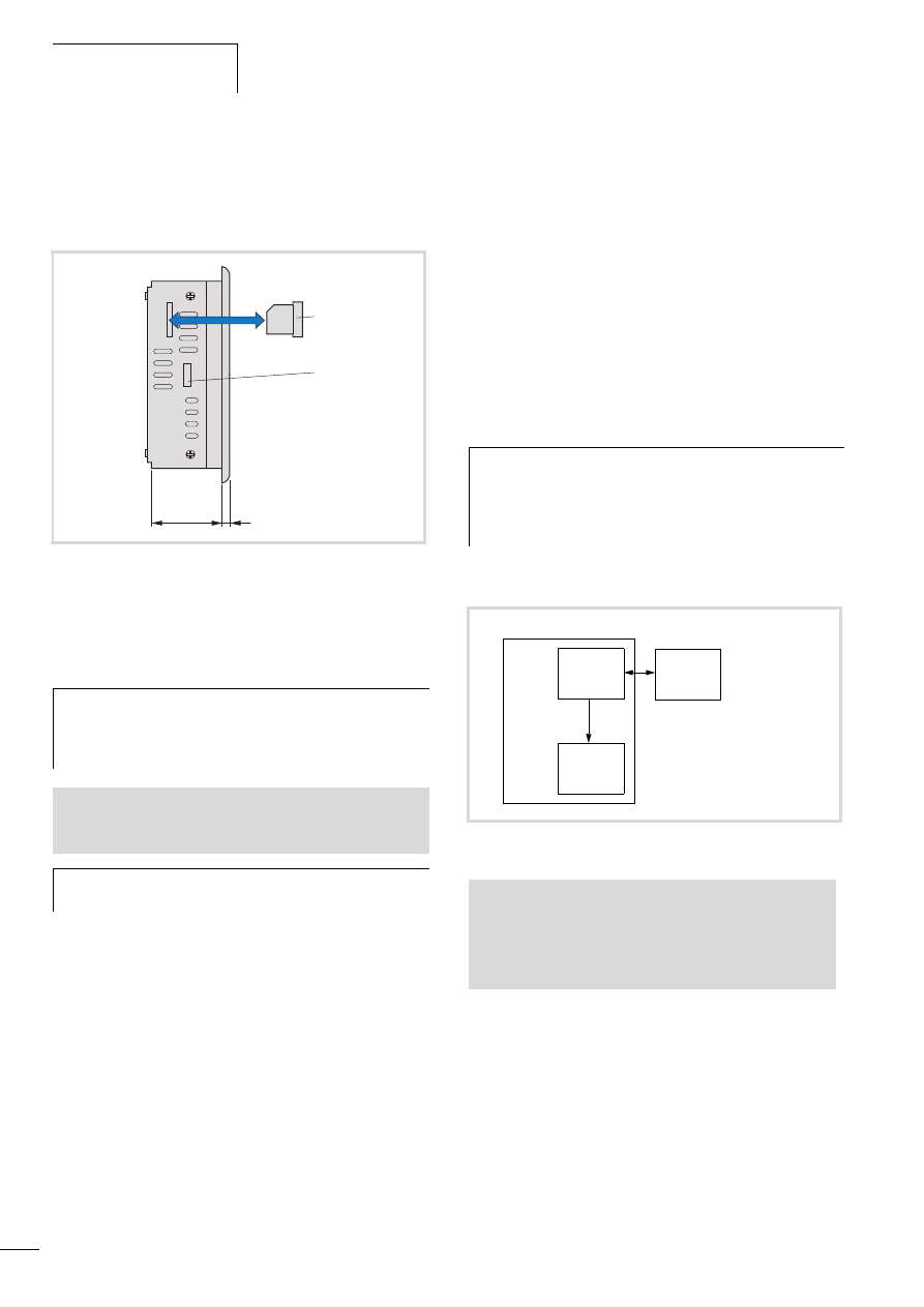
Figure 1: Battery change
Setup of the MFD4
10/10 MN04802002Z-EN
8
Memory card (MCC)
The MMC serves as mass storage memory. You can load the recipe
data, general data and the user program onto them. The operating
system (OS) supports memory types with the FAT16 file system.
You can transfer the operating system (OS) to the memory card in
order to load it from there into other MFD4 devices (OS update).
CPU drives
The MFD4 has the following drives available:
• Internal
– Memory system (disk_sys)
• external, optional
– Memory card (disk_mmc)
The boot system and the operating system are saved in
compressed format and protected against failure of the power
supply in the transaction safe system memory. In the operating
state, the boot project and the relevant sections of operating
system are “unpacked” and copied into the working memory.
The retentive data are stored in the battery-buffered SRAM
memory.
The figure 3 indicates the interaction of the differing memory
systems:
Figure 2: Inserting the memory card
a Memory card
b Tab for fixing bracket
h
Caution!
The file system of the memory card is not transaction-safe.
Make sur that all the files of the program are closed
before you plug or un-plug a card or turn off the voltage.
See also:
• Updating the operating system
• Erase operating system/boot project from the MMC
h
Erasing of files is implemented in the same way as erasing
the operating system.
54
5
a
b
h
Transaction safe means that if there is a voltage dip when
the file is being processed, the file system and the opened
file are generally not destroyed. It is possible however,
that data which you have written into the file last opened
may be lost.
Figure 3: CPU memory organization
See also:
• Data access to the memory card with the aid of
– browser commands such as, for example, copyprojtommc, to copy
the user program onto the MMC
– Functions such as “SysFileOpen” or “SysFileRead”
• Limit values for memory usage.
disk_sys
disk_mmc
System
memory
(flash)
Working
memory
(SDRAM)
MMC memory card

10/10 MN04802002Z-EN
Designations
9
Programming interfaces
Two programming interfaces are provided
• Ethernet interface
• RS232 interface
The operating system processes the Ethernet interface faster than
the RS232. Program transfers or functions for troubleshooting
should therefore be carried out via the Ethernet interface.
The interfaces have the following additional functions.
Ethernet interface
The galvanically isolated interface is used to establish a connection
to the Ethernet network and exchange data with other
PLCs/devices on the network.
RS232 interface
This interface allows you to establish a point-to-point connection
to another device without handshake cables. To do this switch the
interface to Transparent mode by calling the functions from the
SysLibCom.lib library. In this status, the interface is addressed as
COM1. The interface has no potential isolation.
CANopen/easyNet interface
You connect the MFD4 to the CANopen or the easyNet network
via the 9-pole SUB-D connector. Both networks use the same data
cables; the control cables SELECT-IN, SELECT-OUT are also
provided for the easyNet. The control cables enable the MFD4 to
configure the other stations on the easyNet or be configured itself.
The interface is potentially isolated.
The MFD4 can be run as network (NMT) master or as NMT slave
(Device) on the CANopen bus. CANopen and easyNet stations can
be connected to the MFD4 via the same bus.
Behaviour of the stations on the CANopen bus
Node/bus monitoring: CANopen telegrams are sent and received
directly by the user program. An interruption on the CANopen bus
is only detected if the appropriate CANopen nodes are being
monitored by another station (Node guarding function.
Start/Stop behaviour: if you set the STOP position on the operating
mode selector switch, all outputs of the remote devices are set at
the end of the cycle to “0”.
Voltage switch on: The sequence in which the power supply of the
individual CAN slaves is connected does not have an effect on the
functionality of the CAN bus. Depending on the parameters set,
the PLC “waits” for non-existent slaves or starts them when they
are connected to the CAN network.
Communication with CANopen stations: The communication with
the CANopen stations and their configuration is described in the
following online documentation that was installed during the
installation on your computer:
• Engineering CANopen stations (AN2700K27G.PDF)
1)
• Coupling of multiple autonomous controls (CAN-Device) via
CANopen (AN2700K20G.PDF)
2)
• Library description: CANUser.lib/CANUser_Master.lib
(h1554g.pdf)
3)
1) The documentation is located in the directory
C:\Programs\Moeller Software\easy Soft CoDeSys V2.3.5\
easy Soft CoDeSys\APPLICATION-EXAMPLES-NOTES-
MODULES\XCONTROL\CAN\CAN_XC100_XC200\ENGLISH
2) The documentation is located in the directory
C:\Programs\Moeller Software\easy Soft CoDeSys V2.3.5\
easy Soft CoDeSys\APPLICATION-EXAMPLES-NOTES-
MODULES\XCONTROL\CAN\CAN_XC100_XC200\ENGLISH
3)
See also:
• Interfaces
• Assignment of the Ethernet interface
• Establishing a PC – MFD4 connection
See also:
• Interfaces
• Assignment of the RS232 interface
• Establishing a PC – MFD4 connection
h
If an MFD4 is incorporated in the easyNet network, the
baud rate of the stations must not exceed 125 Kbit/s!
See also:
• Manual "control relay easy800" (h1423d.pdf)
• Manual "Data transfer between easy and IEC PLCs (easyNet)"
(h1593de.pdf)
See also:
• CANopen/easyNet

10/10 MN04802002Z-EN
10
10/10 MN04802002Z-EN
11
2 Mounting the MFD4
Mounting/removing the device
The device is suitable for vertical or diagonal (up to 45
°
) mounting
in a control cabinet, a front panel or control desk.
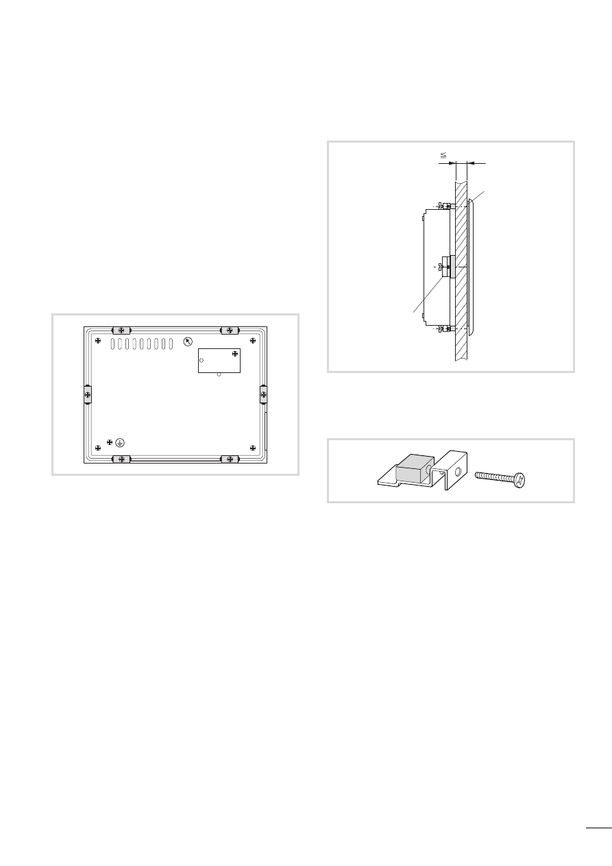
The device is fastened from the rear:
X
Fit the seal flat and evenly between the front panel and the
front plate
X
Tighten the fixing brackets for fastening the device evenly until
the front plate is flat against the front panel.
The device can be mounted in a housing provided that the
permissible ambient temperature is observed, a section
„Technical data“.
e
Mounting dimensions a page 66
Figure 4: Arrangement of fixing brackets
Figure 5: Mounting with the fixing brackets
a Seal (tightly fitted on the device)
b Fixing bracket
Figure 6: Fixing brackets
b
a
12 mm (0.47")

10/10 MN04802002Z-EN
12

10/10 MN04802002Z-EN
13
3 Engineering
Control panel layout
The layout of the components inside the control panel is a major
factor for achieving interference-free functioning of the plant or
machinery. During the project planning and design phase, as well
as its implementation, care must be taken that the power and
control sections are separated. The power section includes:
• Contactors
• Coupling/interfacing components
• Transformers
• Frequency inverters
• Converters
In order to effectively exclude any electromagnetic contamination,
it is a good idea to divide the system into sections, according to
their power and interference levels. In small switchgear cabinets it
is often enough to provide a sheet steel dividing wall, to reduce
interference factors.
Ventilation
In order to ensure sufficient ventilation a minimum clearance of
50 mm to passive components must be observed. If the
neighbouring components are active elements (e.g. load current
distribution, transformers), a minimum clearance of 75 mm must
be observed. The values specified in the technical data must be
observed. Ensure that the device does not overheat during
operation:
X
Keep the cooling slots clear to ensure the cooling of the
system.Keep the cooling slots clear to ensure the cooling of the
system.
X
Avoid direct sunlight on the front.
X
When mounting the device vertically ensure that the angle of tilt
does not exceed 45 degrees.
Preventing interference
Cable routing and wiring
Cables are divided into the following categories:
• Power cables (e.g. cables that carry high currents, or cables to
current converters, contactors or solenoids)
• Control and signal cables (e.g. digital input cables)
• Measuring and signal cables (e.g. fieldbus cables)
Take care to implement proper cable routing both inside and
outside the control panel, to keep interference as low as possible:
X
Avoid parallel routing of sections of cable in different power
categories.
X
As a basis rule, keep AC cable separated from DC cables.
X
Keep to the following minimum spacing:
– at least 10 cm between power cables and signal cables;
– at least 30 cm between power cables and data or analog
cables.
– When routing cables, make sure that the outgoing and return
leads of a circuit pair are routed together. The opposing
currents on this cable pair cause the sum of all currents to
equal zero. The generated electromagnetic fields cancel each
other out.
Suppressor circuitry for interference sources
X
Connect all suppressor circuits as close to the source of
interference (contactors, relays, solenoids) as possible.
Shielding
X
Use shielded cables for the connections to the data interfaces.
The general rule is: the lower the coupling impedance, the
better the shielding effect.
h
Always route power cables and control cables as far apart
as possible. This avoids capacitive and inductive coupling.
If separate routing is not possible, then the first priority
must be to shield the cable responsible for the
interference.
h
Switched inductors should always have suppressor
circuitry fitted.
Engineering
10/10 MN04802002Z-EN
14
Lighting protection
External lightning protection
All cables between buildings must be shielded. Metal conduits are
recommended for use here. For signal cables, use overvoltage
protection devices, such as varistors and surge arresters. .
Implement these measures ideally where the cable enters the
building and at least at the control cabinet.
Internal lightning protection
Internal lightning protection covers all those measures taken to
reduce the effects of a lightning strike and the resulting electrical
and magnetic fields on metallic installation and electrical plant.
These measures are:
• Equipotential bonding/earthing
• Shielding
• Using overvoltage protection devices
Refer to the “EMC engineering guidelines for PS4/PS416
automation systems” (h1287g.pdf) for any questions on cabling
and shielding measures.
Earthing the device
The device housing must always be earthed. The earth connection
(PE) is located on the rear of the device. It must be marked with a
sticker showing the PE earth symbol.
Power supply
Connect the device to the 24 V DC supply. This is fuse protected.
To exchange the fuse the device must be sent to the manufacturer.
There is no potential isolation on the device. Protection against
reverse polarity protects the device from incorrect connection.
Interfaces
Ethernet
Physically the programming device interface is provided as an
RJ45 jack. This means that normal commercial RJ45 connectors or
Ethernet patch cables can be used.
Direct connection PC – MFD4
The MFD4 can be connected directly to the (programming) PC via
a crossover Ethernet cable, a figure 9, 10.
Crossover cables have the following design features:
The following cross-over cables are available:
– XT-CAT5-X-2
2 m long
– XT-CAT5-X-5
5 m long
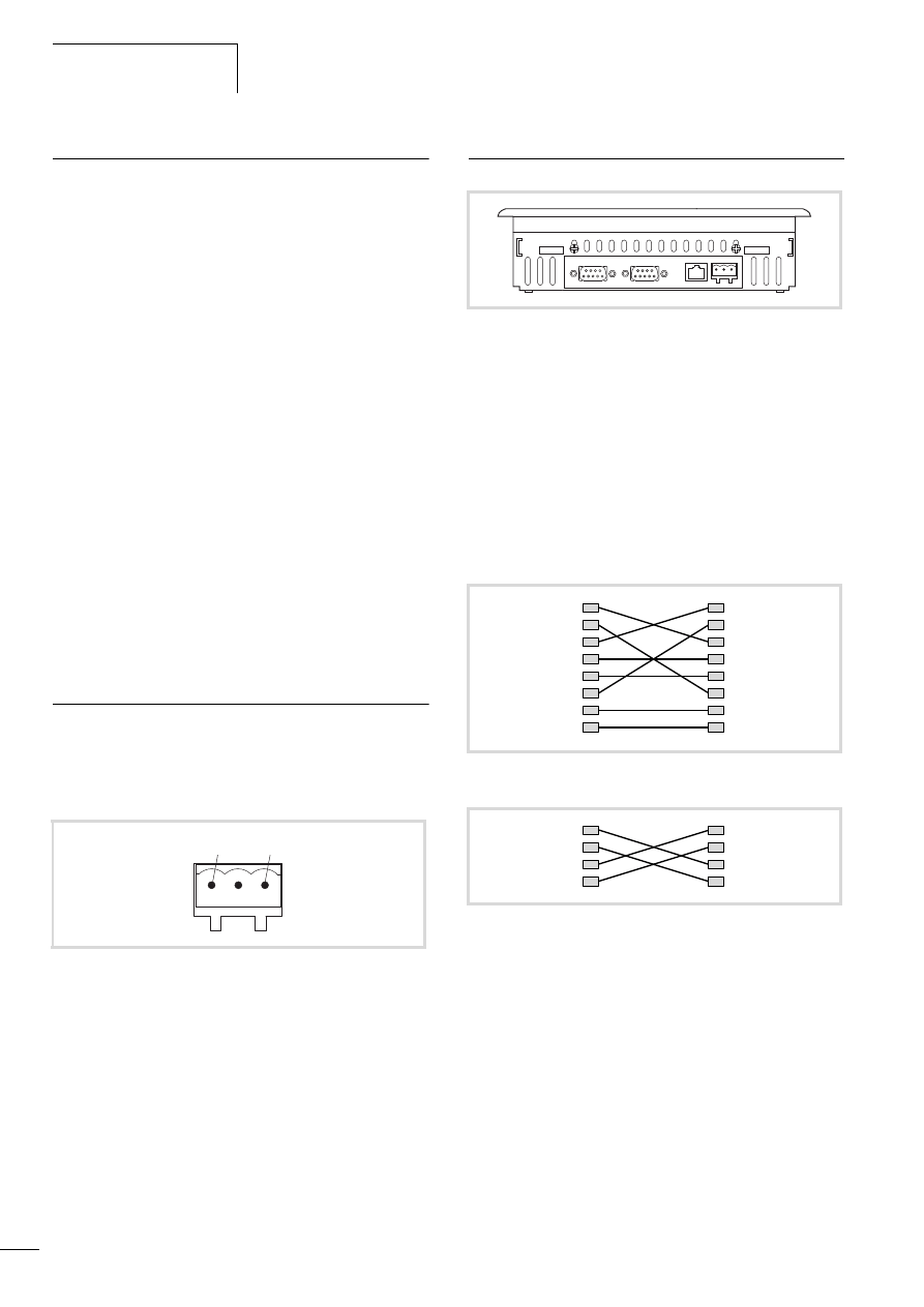
Figure 7: Plug connector to the power supply
a 0 V
b 24 V DC
a
b
Figure 8: Interfaces (from left): CANopen/easyNet, RS232, Ethernet,
24 V DC
Figure 9: Connection set-up of a 8-pole crossover cable
Figure 10: Connection set-up of a 4-pole crossover cable
5
5
6
6
7
7
8
8
1
1
2
2
3
3
4
4
1
1
2
2
3
3
6
6
10/10 MN04802002Z-EN
Interfaces
15
PC – MFD4 via Hub/Switch connection:
If you use a Hub or a Switch between the PC – MFD4 connection,
you must use a standard Ethernet cable which is connected 1:1 for
the connection between PC – Hub/Switch and Hub/Switch –
MFD4.
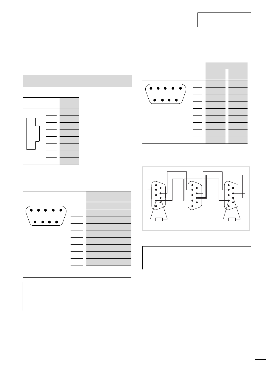
Table 1:
Assignment of the Ethernet interface
RS232
Table 2:
Assignment of the RS232 interface
CANopen/easyNet
Table 3:
Assignment of the CANopen/eásyNet interface
Bus terminating resistors
The first or last station on the bus must be provided with 120 Ohm
bus terminating resistors between the CAN_H and CAN_L cables.
See also:
• Characteristic of the Ethernet cable
RJ 45
PIN
Signal
8
–
7
–
6
Rx–
5
–
4
–
3
Rx+
2
Tx–
1
Tx+
RS232
PIN
Signal
9
–
8
CTS
1)
7
RTS
1)
6
DSR
1)
5
GND
4
DTR
1)
3
TxD
2
RxD
1
DCD
1)
1) The control cables are routed out
but are not active.
h
Caution!
• Do not connect a potential to the control cables.
• If the interface cable is longer than 4 m, connect the
24 V DC power supply via the DEHNrail DR 24 FML
filter (filter manufacturer: Dehn).
1
2
3
4
5
6
7
8
1
6
7
8
9
2
3
4
5
Pin
Signal
CANopen
easyNet
9
–
–
8
–
Select_Out
7
CAN_H
ECAN_H
6
GND
GND
5
–
–
4
–
Select_In
3
GND
GND
2
CAN_L
ECAN_L
1
–
–
Figure 11: Cabling between 3 MFD4
h
You can order a serial interface cable from
Eaton Industries GmbH:
Order code EB-Z/KV/09/11.
Article no. 219690 .
1
6
7
8
9
2
3
4
5
1
2
3
4
5
6
9
8
7
1
2
3
4
5
9
8
7
1
6
120 O
120 O
2
3
4
5
6
9
8
7
SE
LE
CT
_
IN
SE
LE
CT
_OUT

10/10 MN04802002Z-EN
16
10/10 MN04802002Z-EN
17
4 MFD4 operation
Setting parameters
The display can be used to set the following parameters and
execute the following functions:
• Executing a reset
• Set parameters on the display
– User interface for display calibration (Touch tab)
– Entering parameters of the Ethernet interface (TCP/IP tab)
– Setting the time (Clock tab)
– Contrast and brightness setting (Contrast/Light tab)
Executing a reset
In the Setup menu tap the Reset button (a figure 24) in order to
execute a warm Reset.
Setting parameters on the display
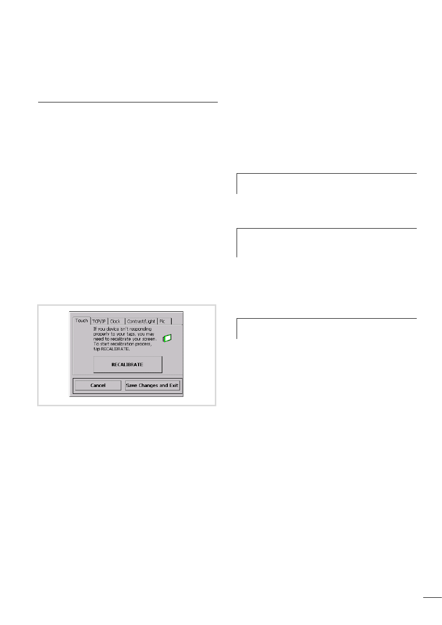
Tap the Settings button to switch the display to the basic menu as
shown in figure 12.
You can now calibrate the MFD4 or select other tabs. In some tabs
you can enter values and addresses via screens and using arrow
keys. The longer you press the button, the faster the value/address
changes. Save the new settings by pressing OK or Save Changes
and Exit.
User interface for display calibration
The system will initiate the calibration process automatically after
loading a new operating system into the MFD4 or carrying out a
reset to restore the factory settings.
If the display does not respond to touch, you should recalibrate it
again. To do this move to the basic menu and tap the
RECALIBRATE button on the Touch tab.
X
Follow the instructions that appear in English on the cross-hair
at the centre of the display.
X
Tap the centre of the cross-hair. This will then move to the top
left corner of the display. Touching the centre of the cross-hair
again will cause it to move along the edge of the display to the
top right corner. At this point two different sets of operations
are possible.
The calibration was carried out correctly. In this case the cross-hair
will disappear and an English text will appear. Ignore this text. The
ESC and Enter buttons mentioned in this text are not provided on
the MFD4.
X
To return to the menu tap the display area.
Calibration was not completed correctly. In this case the cross-hair
returns to the centre of the display. This occurs if the centre of the
cross-hair was not always touched during calibration. The
calibration procedure is restarted. You can repeat or cancel the
process. To cancel the process switch the device off and on again.
Figure 12: Display of the basic menu
h
Calibrate the panel at the ambient temperature at which
you wish to use the device.
h
The ESC button described in the text for aborting the
function is not provided. To cancel the process switch the
device off and on again.
h
Touch the cross-hair on the display until it is displayed on
a different spot.
MFD4 operation
10/10 MN04802002Z-EN
18
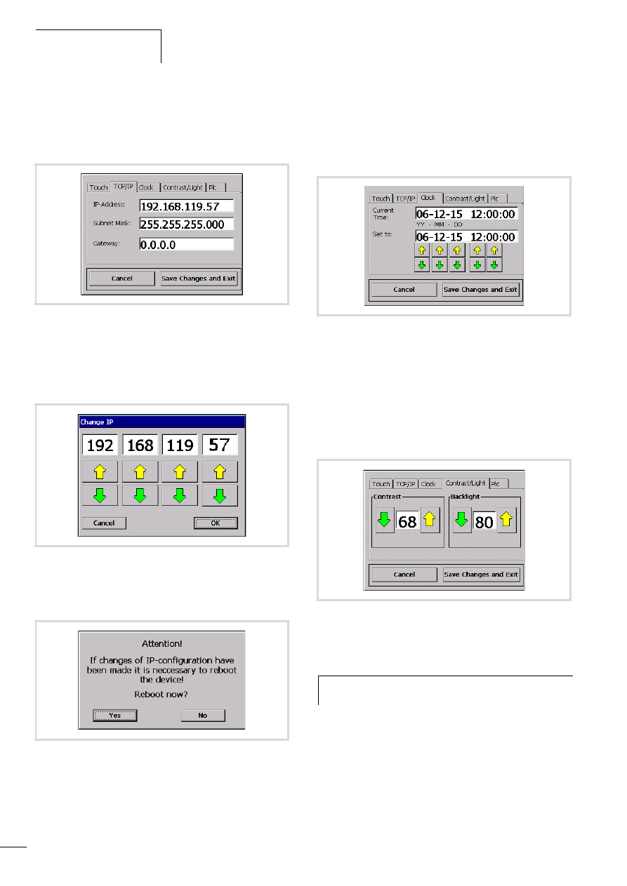
Entering parameters of the Ethernet interface
X
Touch the TCP/IP tab.
This shows the IP address, subnet mask and gateway address.
X
To change address, tap the Address field. The assigned setting
screen appears.
X
Change the address via the arrow buttons and confirm it with
OK.
X
When you have changed all addresses, tap the Save Changes
and Exit button. The display will change:
X
Tap Yes in order to carry out a reboot. The modified addresses
are not accepted until after a reboot has been completed.
During a reboot, the modified data is stored in the registry and
a software reset is carried out.
Setting the time
X
Tap the Clock tab.
This displays the current time that can be changed using the arrow
buttons.
X
Accept the values with the Save Changes and Exit button or
abort the operation with the Cancel button.
Contrast and brightness setting
X
Tap the Contrast/Light tab.
This shows the current values that you can change with the arrow
buttons.
X
Accept the values with the Save Changes and Exit button or
abort the operation with the Cancel button.
Figure 13: Entering Ethernet interface parameters
Figure 14: Screen for setting the IP address
Figure 15: Reboot prompt
Figure 16: Setting the time
Figure 17: Screen for setting the contrast and brightness
h
The contrast can only be adjusted in devices with an STN
display.
10/10 MN04802002Z-EN
Setting parameters
19
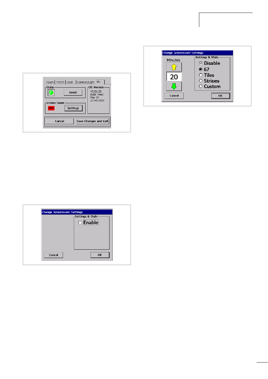
Starting MFD4
X
Tap the Plc tab.
This will show the following status image.
State
The green LED will flash if the device is in STOP mode. If a program
is loaded you can then start it by tapping the Run button.
OS version
The device's operating system version (OS version) is displayed on
the right side of the window. You can also check the version in
CoDeSys by using the "getversion" browser command.
Screen Saver
Use the "Settings" button to access the following menu:
X
Click on the check box next to "Enable". The following status
menu appears:
You can select from four different screen savers under "Settings &
Style". You can customize the "Custom" screen saver according to
your preferences:
X
Place a file of type "bmp" or "jpeg" on a free visualization
page. This file must be named "screensaver.bmp" or
"screensaver.jpg".
X
Transfer your project to the MFD4.
X
Make sure that you have selected "enabled" and "Custom" in
the screen saver system menu.
X
Adjust the time after which the screen saver should be
activated. You can choose between 2 and 100 minutes.
If no input takes place during the specified time, the bitmap/JPG
moves across the display.
X
If you touch the display, the screen saver is deactivated.
Figure 18: Status image for starting the MFD4
Figure 19: Change Screensaver Settings
Figure 20: "Change Screensaver Settings" status menu
10/10 MN04802002Z-EN
20
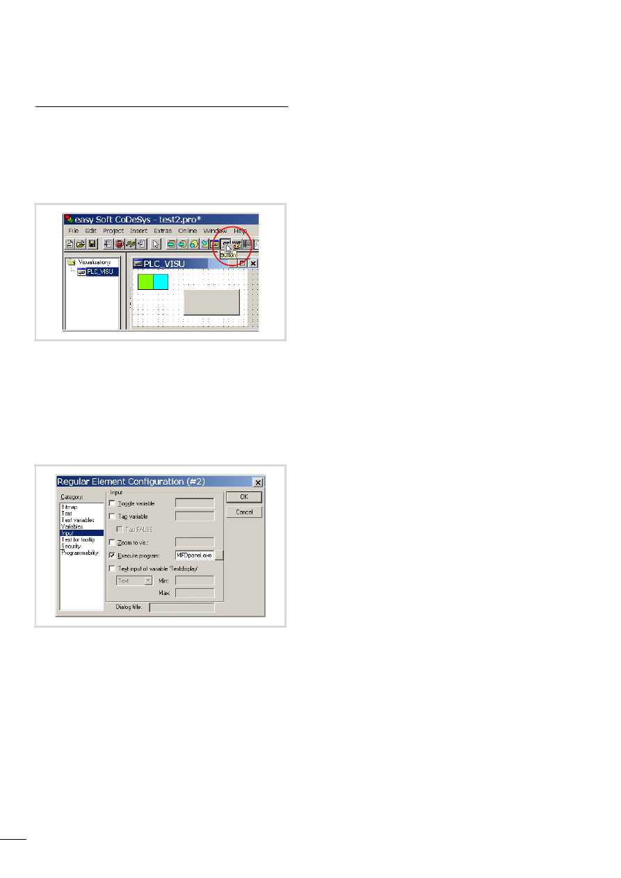
Changing from application screen n basic menu
Changing to the basic menu
X
To change from an application screen to the basic menu, add a
button as shown in figure 21 to the application screen.
X
Double-click the button with the left mouse button. The
window will be displayed as shown in figure 22.
X
Select the Input category.
X
Activate Execute program and in the appropriate entry line
write: MFDpanel.exe.
X
Confirm the entry with the OK button.
You can touch the button after the program is started. The display
with the basic menu will appear.
Changing to the application screen
Touch the Save Changes on Exit button in the basic menu to show
the Reboot screen. Touch No to return to the application screen.
Figure 21: Application with button for changing to the basic menu
Figure 22: Configuring an element
10/10 MN04802002Z-EN
21
5 Operation
Switching on MDF4
Switching on the power supply will cause the display to show a run
of information (information cycle) starting with System start.
If a boot project (with a visualisation task) is on the MFD4 and the
operating mode switch is set to RUN, the first image of the project
is displayed after the information cycle and the PLC program is
started in the background.
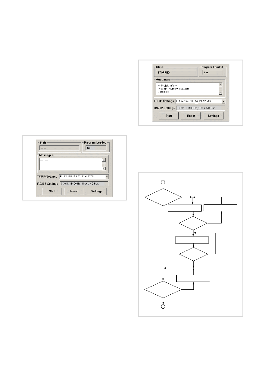
If the device does not contain a boot project and a program the
display shows the Setup Menu 1:
It contains information about the parameters of the Ethernet
(TCP/IP setting) and RS232 interface. The parameters of the
Ethernet interface can be changed on the display (a section
„Entering parameters of the Ethernet interface“, Page 18).
The baud rate of the RS232 interface can be adjusted with the
browser command “setcomconfig” (a section „Setting the
MFD4 communication parameters“, Page 38).
Logging on via the Ethernet interface and transferring a program
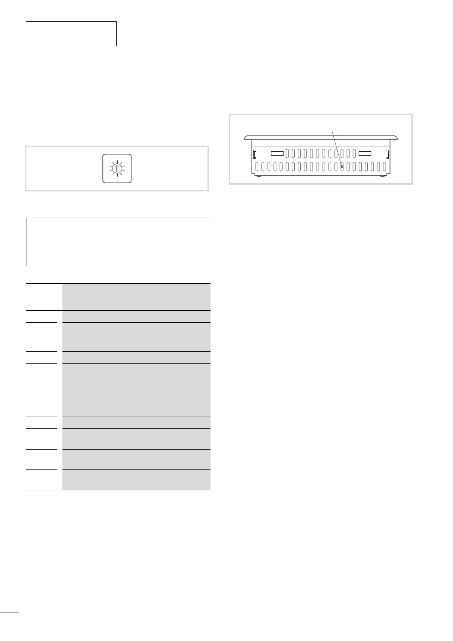
to the MFD4 will refresh the display: The State field will show
STOPPED and the Program Loaded field will show Yes.
The Messages field shows information about the loaded project,
a figure 24.
If the operating mode switch is set to RUN, you can start the
program: In Online mode with the “Start” command or via the
Start button in the Setup menu of the MFD4.
The first screen of the project is displayed and the PLC program is
started in the background.
h
Switching off the device during the startup/information
cycle shortens the lifespan of the display.
Figure 23: Setup menu 1
Figure 24: Setup menu 2
Figure 25: Startup behaviour of the MFD4
OMS = Operating mode switch
Boot project
OMS = RUN
Setup menu 1
Load program!
START
Program load?
Setup menu 2
Setup menu 2
Project Display/Start PLC
Power on
yes
yes
yes
no
no
no
no
yes
Operation
10/10 MN04802002Z-EN
22
Operating mode switch
The operating mode switch enables you to start or stop the MFD4.
You can also carry out a reset in conjunction with the SET button.
The operating mode switch is on the rear of the device. Turning the
switch from STOP to RUN or from RUN to STOP will activate the
required mode immediately.
Table 4:
Operating mode switch functions
SET button
The SET button is used to activate some functions that you have
preselected with the operating mode switch, a table 4
.
Startup behaviour after loading an operating system or
reset
If you have loaded a new operating system in the MFD4 or carried
out a Reset for restoring the factory defaults (a page 26), the
device has the following startup behaviour: switching on the
power supply will cause a bar to appear from the left of the screen
that grows towards the middle. A SYSTEM START is displayed and
carried out. After approx. 60 seconds, the display shows the
message “FORMAT DISK in progress”. The bar grows slowly
towards the right. The display MOELLER Automation appears,
followed by additional information until calibration is initiated,
a section „User interface for display calibration“, Page 17.
Figure 26: Three switch positions
i
Danger!
If the operating mode is switched to position 1 (RUN)
when the MFD4 contains a project, the screen on the
display is refreshed and the PLC program is started
immediately.
Switch
position
Function
0
STOP
1
RUN
To start the project set the operating mode switch to
position 1.
2, 3, 4
STOP
5
Restoring factory settings (factory set)
chapter „Reset for restoring the factory defaults“,
chapter „Startup behaviour after loading an
6
STOP
7
STOP
On pressing the SET button: RESET HARD
8
STOP
On pressing the SET button: RESET COLD
9
STOP
Pressing the SET button: RESET WARM
0
5
1
2
3
4
9
8
7
6
Figure 27: SET button k
k
10/10 MN04802002Z-EN
Startup behaviour of the
program
23
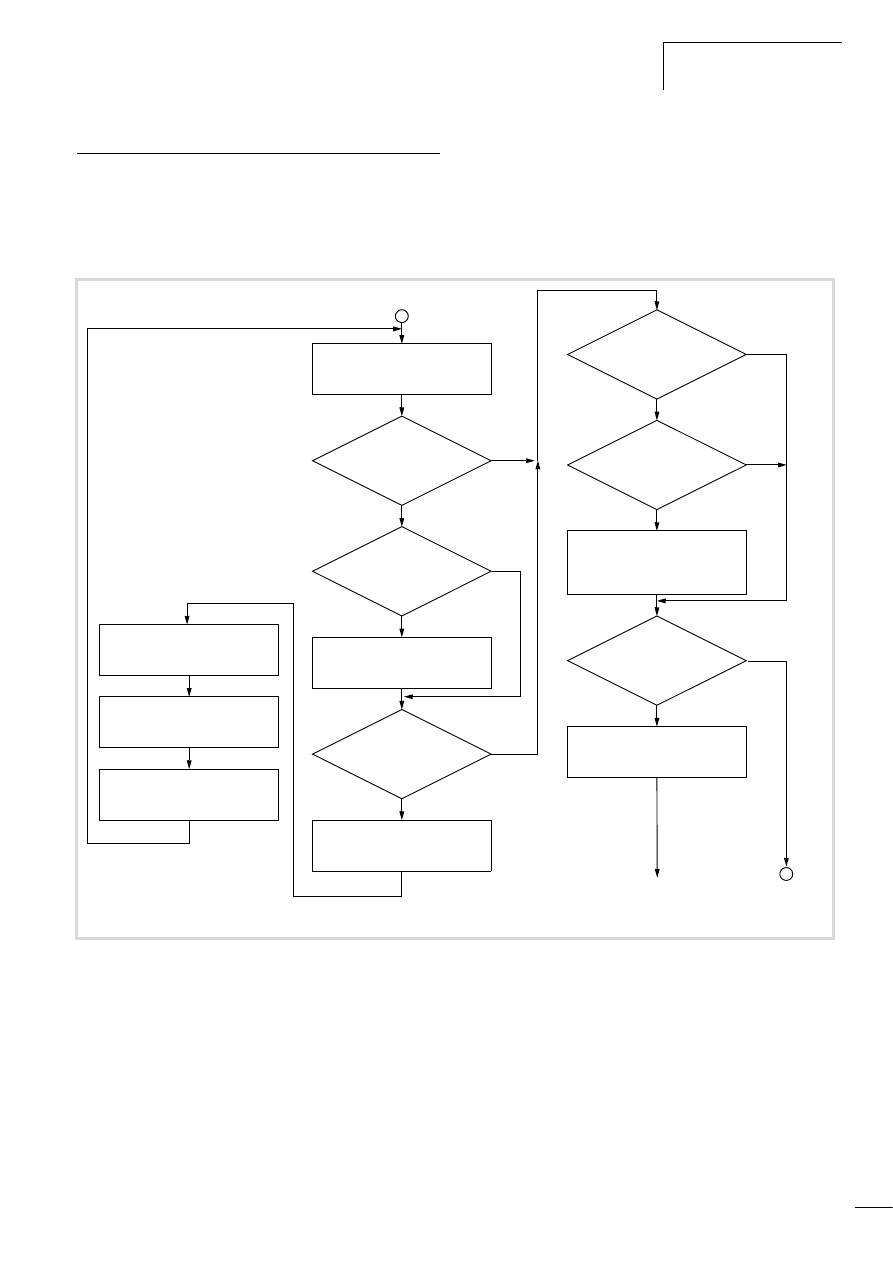
Startup behaviour of the program
Several different user programs/boot projects can be stored on the
MFD4.. They can be located on the memory card, as well as on the
DISK_SYS system memory. However, the MFD4 simply runs one
user program.
The following flow diagram indicates which program is used. The
diagram shows the update of the operating system using the
MMC.
After voltage recovery, a boot project saved in the MFD4 will be
started in accordance with the position of the operating mode
switch and the programmed start conditions.
Figure 28: Start behaviour
User program on MMC k Boot project?
Multiple OS on MMC?
Yes
Yes
System start
Determine newest OS version
User program on MMC?
OS on MMC?
Restore DISK_SYS\project from
MMC\temp. Erase MMC\temp
Yes
Yes
Yes
No
No
Power on
Newest version k DISK_SYS?
Save DISK_SYS\project
on MMC\temp
Format DISK_SYS
Copy OS from MMC to DISK_SYS (LED
flashes faster)
Copy user program from MMC onto
DISK_SYS
(existing boot project will be replaced)
Boot project on DISK_SYS?
Copy boot project
to working memory
No
Yes
No
No
No
STOP
a a on Page 24
Operation
10/10 MN04802002Z-EN
24
Setting the startup behaviour in the programming
software
The start-up behaviour setting primarily defines the handling of
the retentive variables. The following settings are not activated
until the power has been switched on.
Select one of the following start conditions in the “START
BEHAVIOUR” drop-down menu in the “Other Parameters” tab of
the PLC configurator.
• HALT
• COLDSTART
• WARMSTART
HALT
The user project is not started irrespective of the switch position of
the operating mode switch.
COLDSTART/WARMSTART
Precondition: The operating mode switch is in RUN position.
The variables are initialised in accordance with table 5, before
MFD4 starts.
Table 5:
Behaviour of the variables after COLDSTART/WARMSTART
Program start (STOP l RUN)
You have the following possibilities to start the program:
Program stop (RUN l STOP)
Changing the operating mode switch to the STOP position
switches the MFD4 to STOP after the program cycle has been
completed (ending of all active tasks).
After the task has ended the outputs used by the I/O task are set
to 0, a chapter „Program processing, multitasking and system
times“ on Page 29.
You can stop the program in one of three ways:
• In online operation, issue the STOP command.
• Set the operating mode switch to its STOP position.
• Move to the basic menu (a page 20). Open the PLC tab and
tap Reset.
Power off/interruption of the power supply
Switching off/disconnecting the power supply causes an
immediate abort of the program cycle or tasks when a program is
running. The data is then no longer consistent!
All outputs in which the I/O tasks are used are set to 0 or switched
off, a chapter „Program processing, multitasking and system
times“ on Page 29. The behaviour of retentive variables in shown
in can be seen in table 5.
The remaining program cycle will not be completed when power is
reconnected!
If the data integrity is not practical for an application, additional
measures should be engineered, such as e.g. the use of an
uninterruptible power supply (UPS) with battery backup.
The MFD4 is started as shown in figure 28 (Start behaviour).
Behaviour of the variables after …
Variable type
COLDSTART
WARMSTART
Non-retentive
Activation of the initial values
Retain
1)
Activation of the
initial values
Values remain in
memory
Persistent
Activation of the initial values
Retain Persistent
Values remain in memory
1) Physical operands such as I, Q, M cannot be declared as “Retain”
variables.
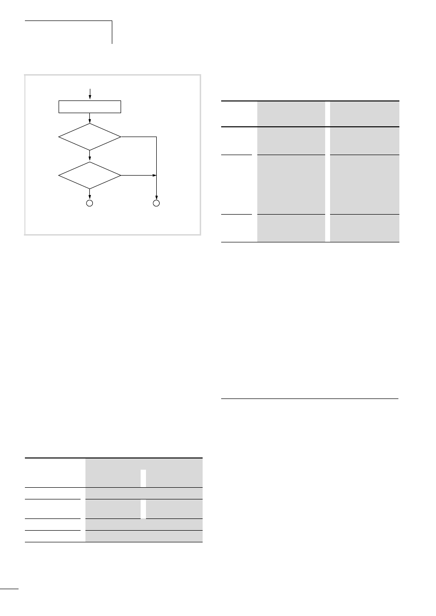
STOP
Operating mode
switch in RUN?
Yes
COLDSTART/
WARMSTART
Start behaviour?
HALT
Load retentive data
RUN
a
a
No
Program exists in main
memory
Program should be
loaded
Pre-
requisite
• MFD4 in STOP
• Operating mode switch
in STOP
• MFD4 in STOP
• Operating mode switch
in RUN
Action
• Set operating mode
switch to RUN or
• in online operation,
issue the “Start”
command.
• Load program
• in online operation,
issue the “Start”
command.
• Tap the Start switch in
the Setup menu of the
MFD4
Result for
all
variables
MFD4 in RUN
Values are retained at the
start
MFD4 in RUN
Initial values are activated.

10/10 MN04802002Z-EN
Test and commissioning
(Debugging)
25
Test and commissioning (Debugging)
The MFD4 supports you during test and commissioning with the
following:
• Breakpoint/single-step mode
• Single-cycle mode
• Forcing
• Online modification, l PLC programming with CoDeSys manual
(h1437g.pdf), Chapter Online functions
• Status indication/Powerflow.
Breakpoint/single-step mode
Breakpoints can be set within the application program. If an
instruction has a breakpoint attached, then the program will halt
at this point. The following instructions can be executed in single-
step mode.
Single-cycle mode
In single-cycle operation, one program cycle is performed in real
time. The outputs are enabled during the cycle. At the end of the
cycle, the output states are cancelled and the outputs are switched
off. Task monitoring is active.
Forcing
All variables of the user program can be forcibly set. A local output
is only forced if the corresponding variable is forced and the CPU
is in the RUN state.
Status indication
The inputs/outputs must be referenced in order to visualize the
states of the inputs/outputs in an interval controlled task in the
PLC configurator. The following syntax is sufficient in the ST
programming language in order to be able to display individual
I/O bits, e.g.:
in IL:
Reset
There are three different types of Reset commands:
• Warm reset
• Cold reset
• Full reset
The commands for initializing a retentive variable range are shown
in table 6 . The commands also affect the state of the CPU:
Warm reset
The program is stopped. The variables are initialized. The program
can be restarted.
Cold reset
The program is stopped. The variables are initialized. The program
can be restarted.
Full reset
The program in the device and the boot project are erased. The
variables are initialised. The device is switch to STOP.
Table 6:
Behaviour of the variables after a Reset
h
Caution!
The outputs that were already set when the breakpoint
occurred remain set!
%IB0; (referencing of inputs I0.0 - I0.7)
%QB0; (referencing of outputs Q0.0 - Q0.7)
LD
%IB0
ST
Default byte
LD
Default byte
ST
%QB0
Reset command
Variable
type
Warm reset
Cold reset
Full reset
1)
Non-
retentive
Activation of
the initial
values
Activation of
the initial
values
Activation of
the initial
values
Retain
2)
Values remain
in memory
Persistent
Activation of
the initial
values
Retain
Persistent
Values remain
in memory
Values remain
in memory
1) After a full reset, the program must be reloaded. In online operation,
the “Start” command can now be issued.
2) Physical operands such as I, Q, M cannot be declared as “Retain”
variables.

Operation
10/10 MN04802002Z-EN
26
Reset for restoring the factory defaults
A prerequisite for the reset is that the operating mode switch is in
position 5.
X
But switch off the supply voltage first!
X
Press the SET button and switch on the power supply again with
the SET button depressed.
X
Hold down the SET button for at least 20 seconds, a section
„Startup behaviour after loading an operating system or reset“
on Page 22.
All interfaces are initialised with default parameters. A loaded user
program, all variables and the boot project are erased in the
system memory (Flash) and on the MMC.
Programs and project
Loading the program
You must log on in order to load recently created or modified
programs. The question “Load the new program?” will appear.
The load operation will start once this prompt has been confirmed.
Program download is monitored.
Creating a boot project
In order to safely store the program, a boot project must be
generated by the user program. With the “Create boot project”
command the program is loaded from the PC into the system
memory and saved as a zero-voltage safe boot project.
The following steps are necessary in order to create a boot project:
X
Change over to the “Online” folder.
X
Select the “Login” command.
X
Select the “Create boot project” command.
Storing the boot project on a memory card
X
Click on the folder Resources l PLC Browser and enter the
“copyprojtommc” command.
The boot project is stored on the MMC in the sub-directory
“project” under the name “Default.prg”. Furthermore a
“Default.chk” file is generated.
You can copy the boot project with the browser commands
“filecopy” or “filerename” (e.g. as a backup copy) and change the
name of the file. In the programming software however only the
boot project with the name “Default” is active.
Deleting a boot project on a memory card
Click on the folder Resources l PLC Browser and enter, for
example, the command for the MFD4.
h
Caution!
Before this operation remove the MMC otherwise the
boot project will be deleted.
h
Please note that the “Retain” variables are initialised
during the load process, but the “PERSISTENT” variables
retain their value.
filedelete \\disk_mmc\\MOELLER\\MFD57\\project\\default.prg
10/10 MN04802002Z-EN
Updating the operating system
27
Updating the operating system
On the MFD4 it is possible to replace the operating system (OS)
by a more up-to-date operating system. Eaton offers the most
recent operating system version for download on the Internet.
ftp://ftp.moeller.net/AUTOMATION/DOWNLOAD/FIRMWARE_UPDATES/
You have two choices available to transfer the operating system
(OS).
• Directly from the PC to the device (only via RS232) a page 27
• From PC via the device to the MMC to the directory
\disk_mmc\moeller\MFD57\ a page 28.
The second variant is only possible for an Ethernet connection!
Transferring the operating system from the PC to the
device
Procedure:
X
Establish a serial connection with the MFD4 via the RS232
interface of the PC. Information on this is provided in the
sections “Interfaces” on Page 14 and “Establishing a PC –
MFD4 connection” on Page 37.
X
Activate the “Other Parameters” tab in the “PLC
Configuration” window and click on the “Start” button.
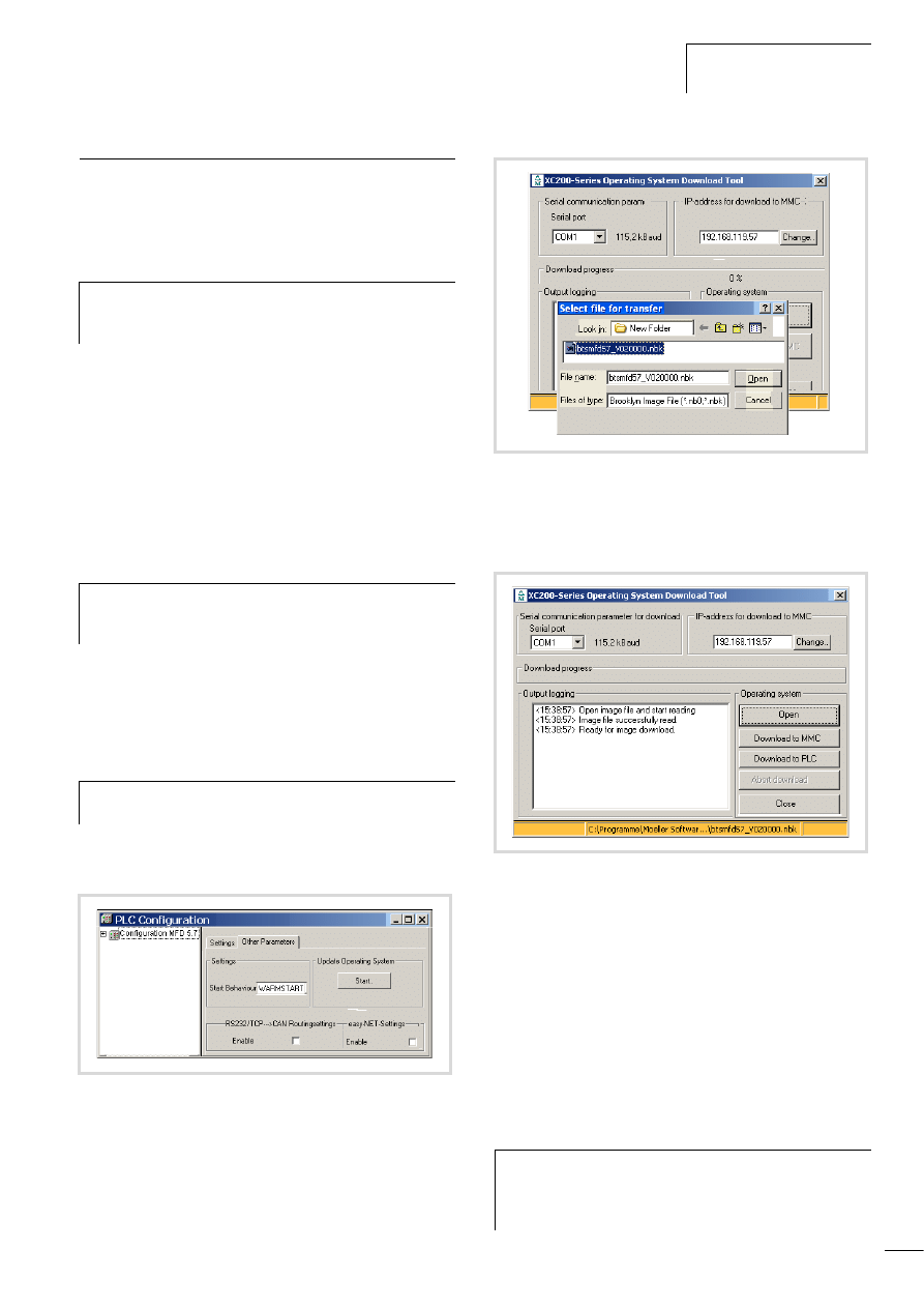
The “Download Tool” window opens.
X
Click on the “Open” button and enter the path in which the
update of the operating system is located.
X
Open the operating system file to be transferred.
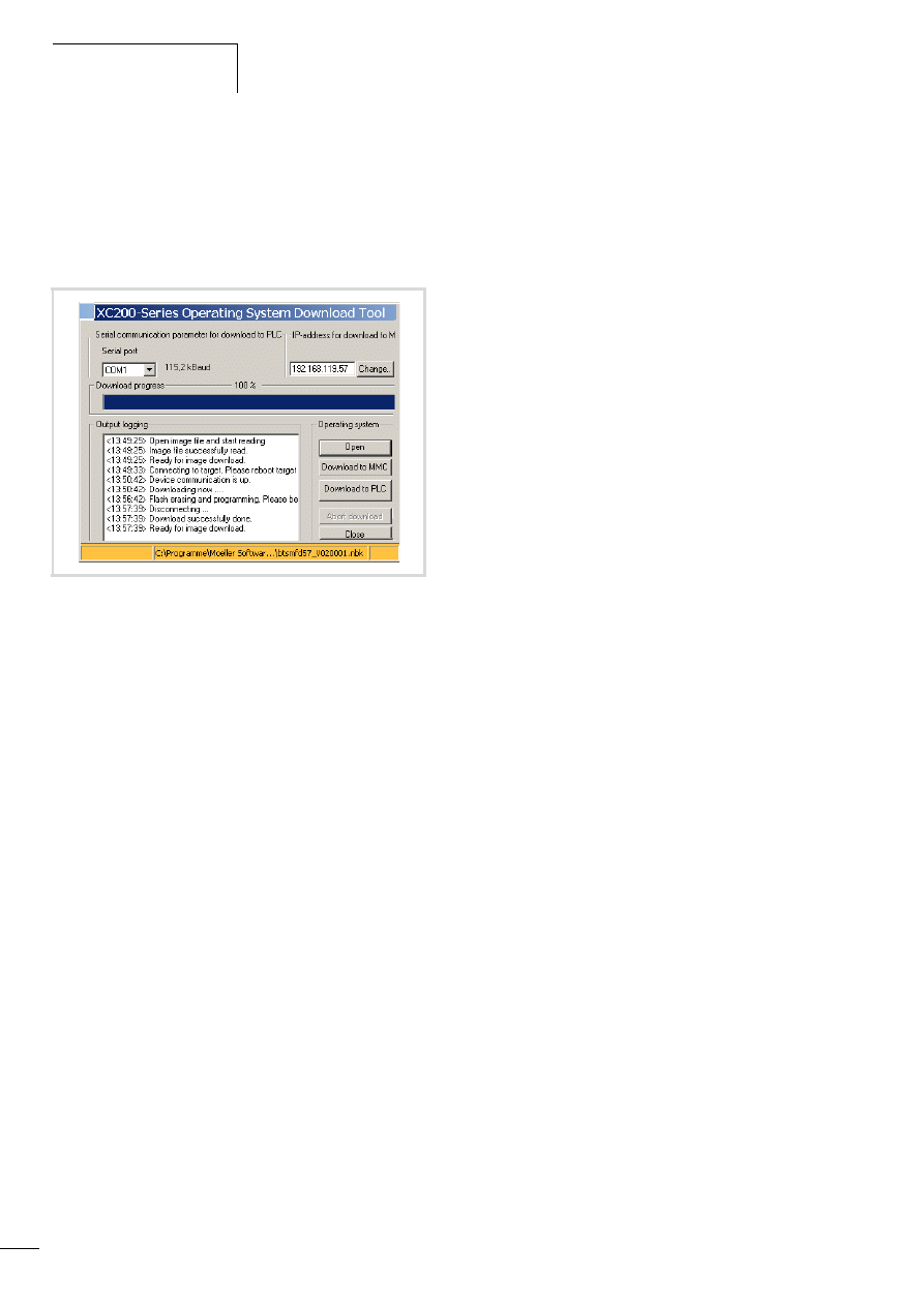
The following window appears:
X
Click on the “Download to PLC” button.
The protocol window shows the message “Connecting to PLC.
Please reboot the MFD4.”
X
Switch off the control voltage of the MFD4 and wait a few
seconds. This will ensure that the residual voltage is discharged.
X
Switch the control voltage of the MFD4 back on.
The transfer of the operating system to the MFD4 is started.
This can take several minutes. During the transfer a progress bar
in the transfer field shows the volume of transferred data as a
percentage.
h
If you transfer a current operating system to an older
hardware version, it is possible that not all functions of
the operating system will be supported by the hardware.
h
If an operating system (OS) is loaded into the device,
the existing operating system (OS) as well as the user
program are deleted.
h
The Baud rate is set to a fixed value of 115200 Bit/s for
loading the operating system.
Figure 29: Updating the operating system
Figure 30: Operating system selection
Figure 31: Download of the operating system
h
Caution!
Please do not engage in the download process until
“Ready for operating system transfer” appears for a
second time on the download window.
Operation
10/10 MN04802002Z-EN
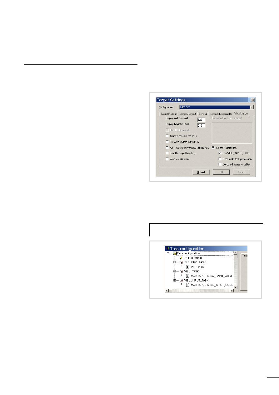
28
When the transfer display shows 100 %, the message “Flash
erasing and programming. Please be patient” appears in the
protocol window.
Further entries will appear in the protocol window. Only when the
entry “Ready for image download” appears a second time is the
download completed.
X
End the download with the “Close” button.
The message “FORMAT DISK in progress” and a status bar appear
on the display. Wait until the bar has covered the entire width of
the screen, the system information was displayed in an image
sequence and an English text appears with a cross-hair in the
middle of the screen. Now calibrate the device.,a chapter „User
interface for display calibration“ ,Page 17.
Transferring the operating system from the PC into the
MMC
PC l MMC
The process is similar to the transfer of the OS from the PC to the
device. Simply click on the button “Transfer OS to MMC”
(see a figure 31).
MMC l Device
Transfer the OS to the device. The OS is updated on power up
a figure 28 on Page 23.
Erase operating system/boot project from the MMC
You can delete the operating/boot project system from the PC, e.g.
with Internet Explorer.
X
Establish a connection to the MFD4 via the default address
“ftp://192.168.119.57“
X
Open the “disc_mmc\moeller\MFD57” directory.
All the operating system files are stored in this directory and can
be deleted there.
Figure 32: Download of the operating system ended
10/10 MN04802002Z-EN
29
6 Program processing, multitasking and system times
Task configuration
The project can be controlled using several tasks. Each task can be
assigned with a range of programs which should be run during
execution of the task.
The task is defined by a name, a priority and a type which defines
under which conditions a task starts. Task condition and priority
determine the sequence in which the tasks are to be processed.
You can set Cyclical or Event-triggered as a task condition:
a cyclical task is restarted after the set interval time. An event-
triggered task is only started if the event occurs. Moreover, you
have the option of coupling system events such as "Start" and
"Stop" with the execution of a certain program.
The task priorities can be parameterized with a value from 0 to 31
where 0 is the highest priority and 31 is the lowest priority.
Before every task is called the output image is always written to
the physical outputs and the input image is read (updating of the
input/output image). The task is executed thereafter. In addition,
all system activities are carried out before or after the task call.
This includes for example, communication with the programming
software, Online changes etc...
The updating of the input/output image of several tasks is
described in section “Multitasking” on Page 32.
All IEC tasks, including those with the highest priority can be
interrupted by an interrupt or an event controlled task.
Time monitoring can be activated for each task (Watchdog).
section “Creating a task (example)” on Page 30 explains the PLC
settings by means of an example. A detailed description of task
configuration, interval times and priorities is provided in the online
documentation PLC programming with CoDeSys 2.3 (h1437g.pdf)
and the CoDeSys visualisation (h1528g.pdf) in the chapter Target
visualisation.
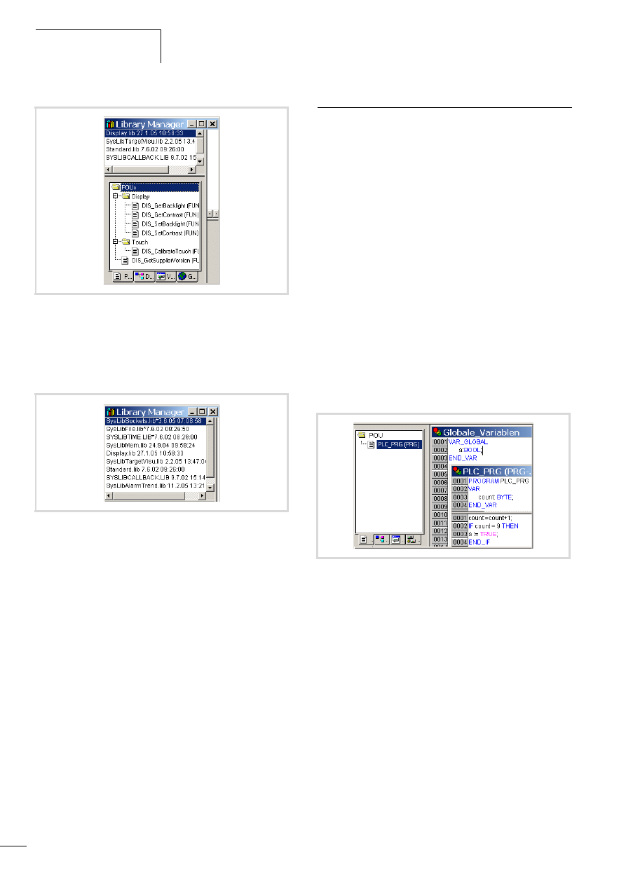
Standard task of the visualisation
After the MFD5.7 is selected, the functions Target Visualisation
and VISU_INPUT_TASK are always activated in the Target Settings
window.
The cyclical tasks are created in the task configuration shown in
figure 34. Default values were entered for the interval times and
priorities. For example, an interval time of 10 ms was entered for
the PLC_PRG_TASK, which is configured as a user task.
The SysLibTargetVisu.lib library is included in addition to the
standard library on the tab Resources l Library Manager. The
library Display.lib must be incorporated in the Library Manager if it
is necessary to use the program in order to change display settings
such as the contrast.
Figure 33: Target settings
h
The interval time should not be less than 10 ms otherwise
there will be too much delay in the visualisation.
Figure 34: Task configuration
Program processing,
multitasking and system times
10/10 MN04802002Z-EN
30
You can activate alarm handling and trend data storing in the
Target Settings (a figure 33). These selections add the
ALARM_TASK and TREND_TASK to the task configuration.
The Library Manager then contains the following libraries:
Creating a task (example)
The section “Creating the event-triggered task “Param” and
defining the program call” on Page 31 describes the basic steps for
creating a task.
The following example uses two tasks:
The first task PLC_PRG_TASK with the program call PLC_PRG() is
already added to the task configuration after the MFD4 is selected
as target system (a figure 34).
The second task “Param” with the program “Param_prog” is
event-triggered and must be created from scratch.
In the program PLC_PRG (PLC_PRG_TASK) a variable “a” is set
that is to call the event-triggered task “Param”.
Creating the “PLC_PRG” program
X
Move from the task configuration to the POUs tab and right-
click on the default program POU PLC_PRG. Enter the program
as shown in figure 37.
Function of the program: The variable “count” is incremented.
On counter status = 9, a = TRUE.
Figure 35: Library manager with display functions
Figure 36: Libraries for alarm and trend functions
Figure 37: Creating a POU for a cyclic task
10/10 MN04802002Z-EN
Creating a task (example)
31
Creating the event-triggered task “Param” and defining
the program call
The following steps are necessary in order to create a task:
• Create POU (object) and program
• Add a task
• Define the program call
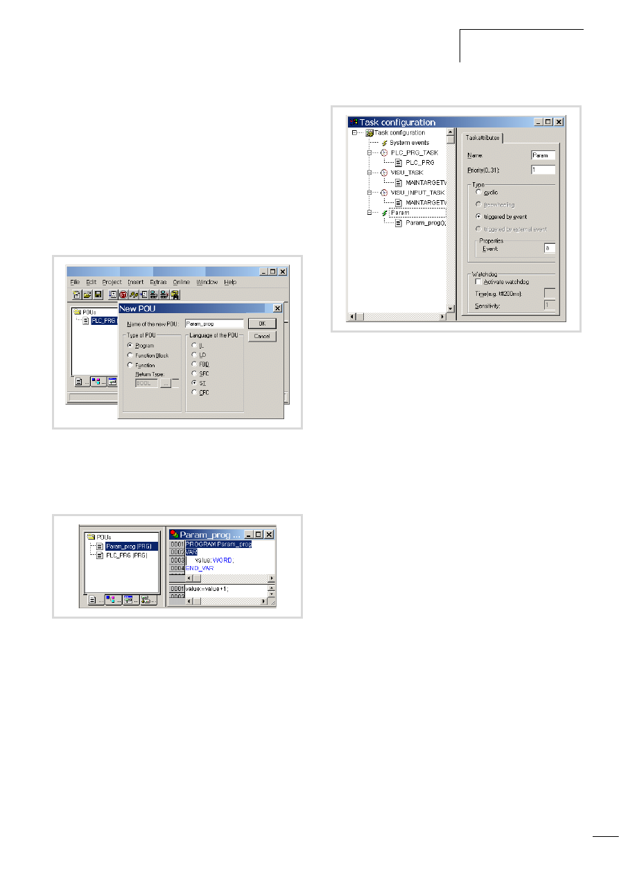
Creating a POU and program
X
Change over to the “POUs” tab and insert a program type
object (POU) with the name “Param_prog”.
X
Enter the program as shown in figure 39. The program
“Param_prog” is processed if the variable a = TRUE.
The variable “value” is then incremented by 1.
Creating a task “Param”
X
Open the “Task configuration” folder in the “Resources” tab
X
Click with the right mouse button on the “Task configuration”
folder and select the “Add task” command in the popup menu.
X
Enter in the Name field a name such as “Param”.
X
Change the task type by activating the Triggered by event
option.
X
Define the Boolean variable “a” as the result of the event,
a figure 40.
X
Click on the “Task configuration” folder and the configuration
is accepted.
Defining the program call (Param_prog)
With the program call you define which program is to be called
with the task “Param”.
X
Click with the right mouse button on the lightning symbol of the
“Param” task created beforehand and select the “Program
call” command in the popup menu.
X
Enter the name “Param_prog” in the “Program call” window.
X
Click the button at the end of the entry field.
X
Select the name in the Input Assistant window and confirm the
selection.
Figure 38: POU for event controlled task
Figure 39: POU for event-triggered task
Figure 40: Parameterisation of the event-triggered task
Program processing,
multitasking and system times
10/10 MN04802002Z-EN
32
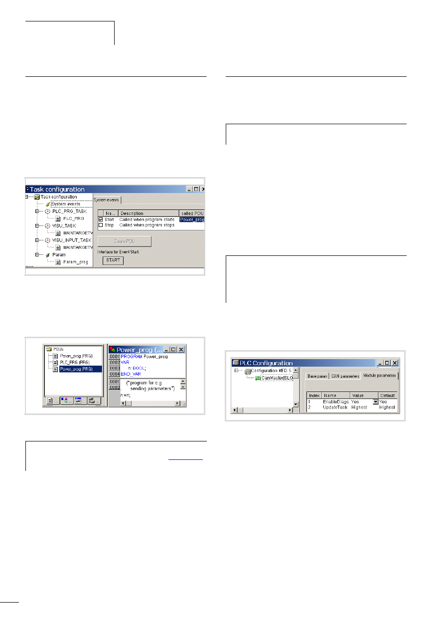
System events
A POU can be called with the help of a system event (state change
of the CPU l STOP/ l START). It can be used when the PLC is
started to initialise modules with parameters. The system events
are independent of the task!
Assigning a POU to a system event
X
Activate the "Start" event (for example) in the task
configuration, under "System Events", and enter the name of
the POU (e.g. Power_prog) that should be processed.
X
Change over to the “Resources l Global variables” and add
the object (POU) “Power_prog”.
X
Program the application:
Multitasking
The MFD4 run time system is a multitasking system. This means
that multiple-tasks can be practically performed at the same time
(in parallel).
Update CANopen variables with multitasking
When using a CANopen master, the update of CAN variables is
associated with a so-called update task. All CAN variables should
be programmed in this task as all CAN variables are updated when
the update task is called.
An existing task that has the highest priority functions as an
update task. If another task is to take on the update function, the
name of the new task must be entered in the Module parameters
tab. The task should have a high or the highest priority.
When you incorporate the CAN master in the configuration, an
entry with the name update task will appear in the Module
parameters tab and the name Highest will appear in the Value
column.
The name “Highest” indicates that the update of the CAN
variables is associated with the task with the highest priority.
This allocation can be changed: use the name of an existing task
instead of “Highest” or create a new task with the name that you
assign instead of Highest.
The name “Highest” was changed in PLC_PRG in figure 44. The
task should be assigned a high priority.
Figure 41: Assigning the POU to a system event
Figure 42: Programming a POU
h
Further information on system events is provided in the
manual “PLC programming with CoDeSys”
)
and in the online help of the programming software.
h
Up to 10 tasks are possible. The parameterisation of a
task as “free wheeling” is not supported.
h
A multitasking system can contain individual tasks which
can be interrupted as required according to their priority.
If the update task has a low priority, it can be interrupted
by a higher priority task. This behaviour may cause an
inconsistency of the CAN variables.
Figure 43: CANopen master update task

10/10 MN04802002Z-EN
Task monitoring with the
watchdog
33
Task monitoring with the watchdog
The processing time of a task can be monitored in terms of time
required using a watchdog. The following applies for defining the
monitoring time:
Processing time < Interval time of the task < Watchdog(time)
If the processing time exceeds the interval time, the end of the
second interval time is awaited until the task is restarted
(l Watchdog deactivated).
The watchdog interrupts the program processing if the processing
time of the task exceeds the watchdog time.
Furthermore, the frequency (sensitivity) can be set, which the
number of exceeds allows. In this case the outputs of the PLC are
switched off and the application program is set to the HALT state.
Afterwards, the user program must be reset with RESET.
Watchdog configuration
You can preselect the following settings in the task configuration:
• Watchdog on/off
• Watchdog time
• Watchdog sensitivity.
These settings apply for time controlled and event controlled tasks.
Watchdog active
The watchdog is started at the commencement of every processing
cycle and reset again at the end of the task.
If the processing time is longer than the watchdog time (sensitivity
= 1) – e.g. with a continuous loop in a program – the watchdog
becomes active. If the processing cycle is shorter than the
watchdog time, the watchdog is not activated.
The triggering of the watchdog continues to be dependent on the
watchdog sensitivity. The watchdog sensitivity determines the
number of successive watchdog timeouts after which the
watchdog is triggered.
The watchdog is triggered:
• immediately when the watchdog time is exceeded with a
watchdog sensitivity of “1”.
• immediately after the “x”th consecutive time that the watchdog
time is exceeded with a watchdog sensitivity of “x”.
For example, a task with a watchdog time of “10 ms” and a
watchdog sensitivity of “5” will end at the latest after 10 ms x 5
= 50 ms.
Figure 44: Changing the name of the CANopen update task
h
If the watchdog is deactivated, task monitoring does not
occur!
j
Danger!
If you want to parameterize a task without a Watchdog or
want to deactivate the Watchdog at a later time, all the
outputs which have been accessed up to this time can
continue to remain active. This is the case for example,
when the task can't be ended due to a continuous loop
(programming error) and/or missing end condition. These
outputs continue to retain their “High potential” until the
operating mode is changed from RUN to STOP or until the
control voltage for the outputs is switched off.
h
The following rule applies for definition of the watchdog
time with several tasks: each watchdog time must be
longer than the sum of task interval times.
Program processing,
multitasking and system times
10/10 MN04802002Z-EN
34
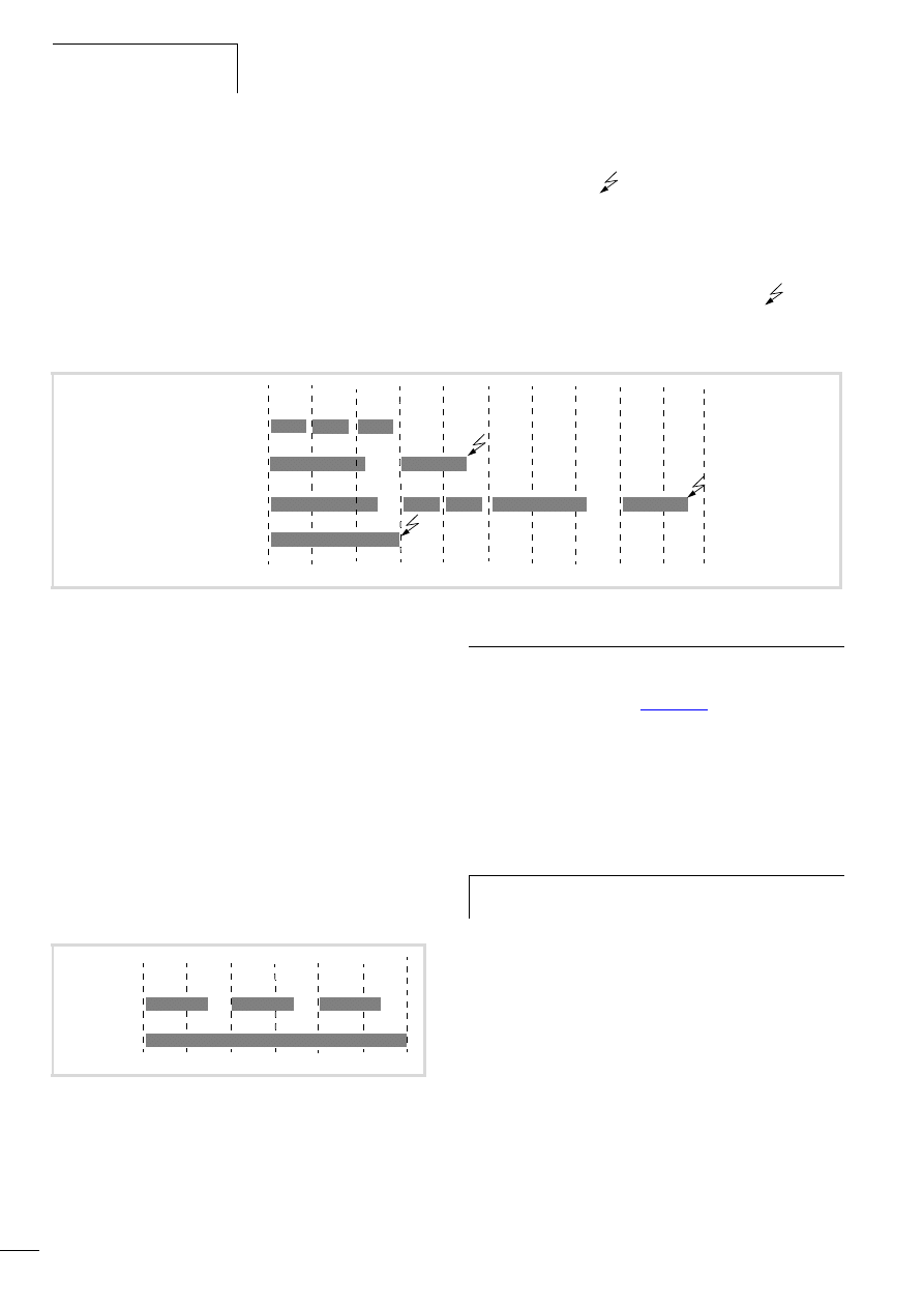
The interaction of interval time (IT), task run time (TT), watchdog
time (WT) and watchdog sensitivity are illustrated by the following
configuration example:
• Watchdog on
• Watchdog time (WT) = 15 ms
• Watchdog sensitivity = 2
The interval time (IZ) of the task is 10 ms.
Variant a: The watchdog is not triggered as the task time always
remains below the defined watchdog time.
Variant b: The watchdog is triggered 15 ms after commencement
of the second interval
, as both times are longer than the
defined watchdog time and occur consecutively.
Variant c: The watchdog is triggered 15 ms after commencement
of the second consecutive task, which is longer than the defined
watchdog time.
Variant d; Endless loop: The watchdog is triggered
, because
the task time takes longer than the watchdog time multiplied by
the watchdog sensitivity (15 ms x 2 = 30 ms).
Watchdog deactivated
The execution time of a task is not monitored when the watchdog
is deactivated. If a task has not ended within the preselected
interval time when the watchdog is deactivated, this task will not
be called or started in the following cycle. A task is only started
again if it has been ended in the previous cycle.
The interval time (IT) is 10 ms.
Variant a: The interval time (IT) of a task was set to 10 ms. The
actual task time (TT) is 15 ms. The task is started on the first call
but is not terminated before the second cycle. Therefore, the task
is not started again in the second cycle. Only in the third cycle –
after 20 ms – is it possible to restart the task. The task does not
run every 10 ms but rather only at a time interval of 2 x 10 ms.
Variant b: The running cycle is not ended.1
Multiple tasks with the same priority
You can assign several tasks with the same priority. The tasks are
split according to the “Time Slice” principle and are practically
executed simultaneously as part intervals (Round Robin).
Web visualization
The description of the web visualisation is provided in the
“The CoDeSys visualization” (
The specific call for the web visualization is as follows:
http:\\192.168.119.57:8080/webvisu.htm
(Prerequisite: You have not changed the default setting of the IP
address! Default setting for MFD4)
If you have changed the IP address, replace the IP address in the
“http:\\…” call with the address you have selected.
Figure 45: Watchdog active, multiple tasks with differing priority
TT < WT TT < WT TZ < WT
TT > WT
TT = WT
TT > WT
TT < WT TT < WT
TT > WT
TT = WT
IT
IT
IT
IT
IT
IT
IT
IT
IT
IT
a TT < WT
b TT > WT
c TT k WT
d TT > WT
(continuous
loop)
TT > 2 x WT
IT = 10 ms
Figure 46: Watchdog deactivated
TZ > IZ
IZ
IZ
IZ
IZ
IZ
a TZ > IZ
b TZ > WZ
(endless loop)
TZ f WZ
TZ > IZ
TZ > IZ
IZ = 10 ms
IZ
h
Caution!
A max. of 10 clients may access the MFD4!
10/10 MN04802002Z-EN
Limit values for memory usage.
35
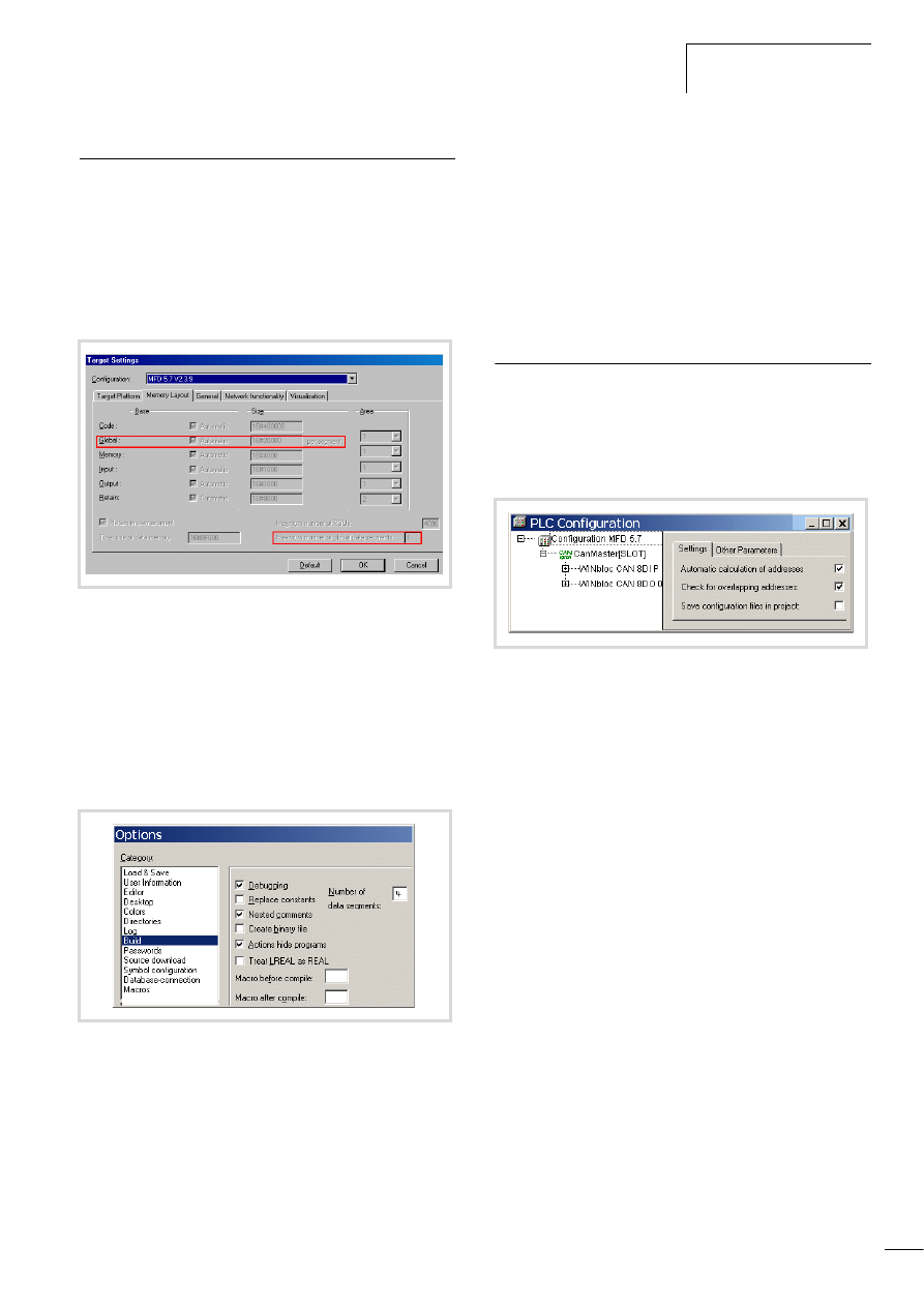
Limit values for memory usage.
The data memory is divided into memory segments. The memory
size of the individual segments can be found in figure 47.
The global data utilises multiple segments. The required amount
can be specified to suit the size of the loaded program.
The segment size can be seen under ‹Resources l Target settings
l Memory layout›: The number of global segments is set to 1 by
default.
To allow optimized, efficient usage of the memory range available
for global data, set the number of global data segments to 4 when
you create a new project.
The number of segments is changed as follows:
X
Select ‹Project l Options l Build options›; select the data
segments field and enter the number of segments listed above
for the respective device type.
Address range
Addresses can only be assigned within the valid ranges.
The range details can be found under ‹Target Settings l Memory
Layout l Size›.
The addresses are checked during compilation. It is essential to
ensure that the addresses of the configured module are used
(referenced) in the program. If the address exceeds the range, a
fault is signalled.
Addressing inputs/outputs and marker
The following functions for addressing are activated by default in
the PLC configuration of a new project:
• “Activate Automatic addresses”
• Address overlaps
Activate "Automatic addresses”
In this function the addresses are automatically assigned or
modified when changing or adding a module. If you add a module,
the addresses of all subsequent modules (irrespective of the line)
are adjusted by the address number of the added module.
Modules that are located in front of the added module in the
configuration are not changed. If you remove the tick at Automatic
calculation of addresses, the addresses are kept in the event of
changes/additions.
Activate "Check for overlapping addresses"
If the check for overlapping addresses is activated, addresses
which are assigned twice will be detected and an error message is
generated during compilation. This setting should not be modified.
Figure 47: Size of the memory segment for global data.
Figure 48: Memory management: Change the number of data
segments
Figure 49: Default setting of the addressing
Program processing,
multitasking and system times
10/10 MN04802002Z-EN
36
Free assignment or modification of addresses of
input/output modules and diagnostic addresses
Depending on the module, you can assign/modify the input,
output and the diagnostics(marker) addresses:
In order to make the modifications visible in the PLC configurator
it is necessary to click once on the PLC Configurator or to select
another module after the address has been edited. They will be
accepted in all cases during compilation.
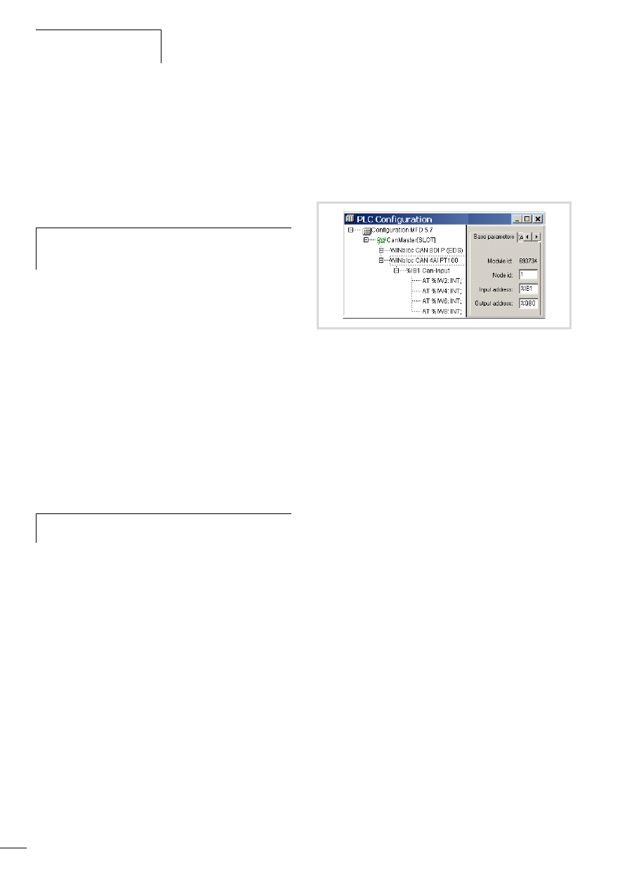
Run “Automatic calculation of addresses”
With the “Automatic calculation of addresses” function which you
can run either via the context menu or the menu bar, all the
respective addresses are recalculated. If you are dealing with a bus
master module, the calculation is also carried out for the modules
which are constituents of the slave on the bus line. The freely
entered addresses of subordinate modules are overwritten when
the address of a higher level module is calculated. If the addresses
have changed and you wish to implement the “Automatic
calculation of addresses”, you must first of all activate the change.
Click first of all on the node to drop down the structure or set the
cursor in the PLC Configuration field and press the left mouse
button.
If you mark the “Configuration MFD 5.7” text and call the
“Automatic calculation of addresses”, all the addresses are
recalculated.
Uneven word addresses
(Independent of the “Check for overlapping addresses” setting)
If you assign an uneven offset address to a word addressable
module in the “Input address” field, e.g. IB1, the following even
word address (IW2) will automatically appear in the PLC
configurator.
h
Caution!
The function Automatic calculation of addresses arranges
the freely assigned addresses in ascending order.
h
Enter the addresses in an ascending order and in
continuous blocks.
Figure 50: Uneven address
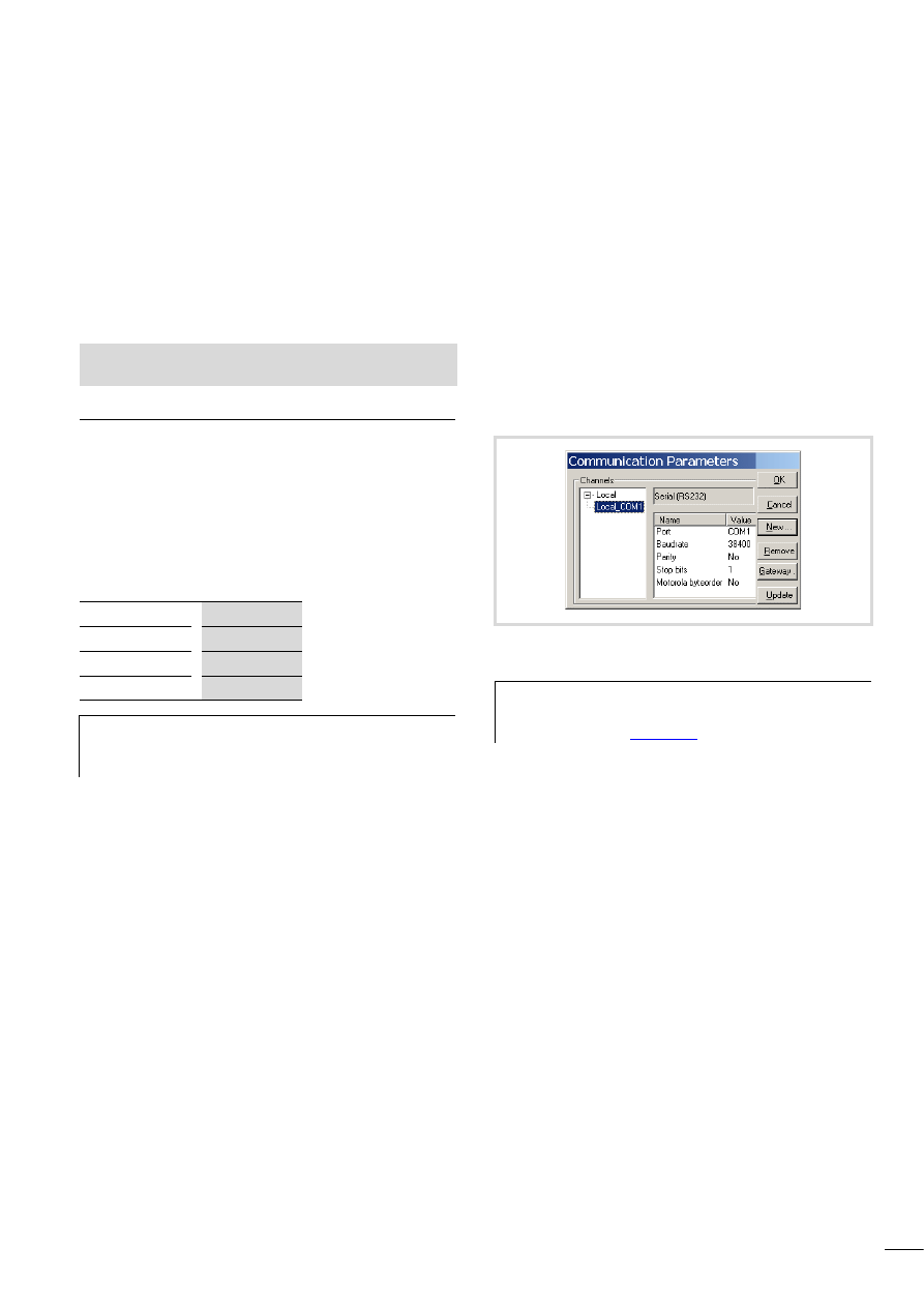
10/10 MN04802002Z-EN
37
7 Establishing a PC – MFD4 connection
The connection between the PC and MFD4 can be established via:
• the RS232 interface
• the Ethernet interface
In this chapter you will get to know the settings to be made in the
programming software.
Connection set-up via RS232 interface
To establish a connection between PC and MFD4, the two devices’
communication parameters must be the same.
• To match them, first adjust the PC’s communication parameters
to the MDF4’s standard parameters settings a section
„Setting the PC communication parameters“.
The MFD4 features the following standard parameters:
• After logging on the MFD4 parameters can be redefined
(a section „Setting the MFD4 communication parameters“,
Page 38).
Setting the PC communication parameters
In the programming software define the communication
parameters of the interface. You can use either the COM1 or the
COM2 port of the PC.
X
In the Online menu, select Communication l Parameters.
X
Specify the port (COM1 or COM2), a section „Changing
settings“
X
Use the remaining settings as shown in figure 51.
X
Confirm the settings with OK.
X
Log on to the device.
You can also select the communication channel “serial (RS232)
(Level 2 Route)” and set a target ID. If you enter a 0 as target ID,
communication is carried out with the local device.
Changing settings
Proceed as follows in order to change parameters such as baud
rate or port:
X
Double-click the value, such as 38400. The field will be
underlined in grey.
X
Enter the desired value.
Double-clicking this field once more to choose the Baud rate, e.g.
57600 Bit/s.
See also:
• Interfaces
Baud rate
COM1
Parity
38400
Stop bits
1
Motorola Byte
No
h
If you get an error message during login, the MFD4’s
default settings have already been changed. In that case
try a baud rate of 57600.
Figure 51:Setting communication parameters
h
Other information on communication parameters is
provided in the manual “PLC programming with
CoDeSys 2.3” (
).
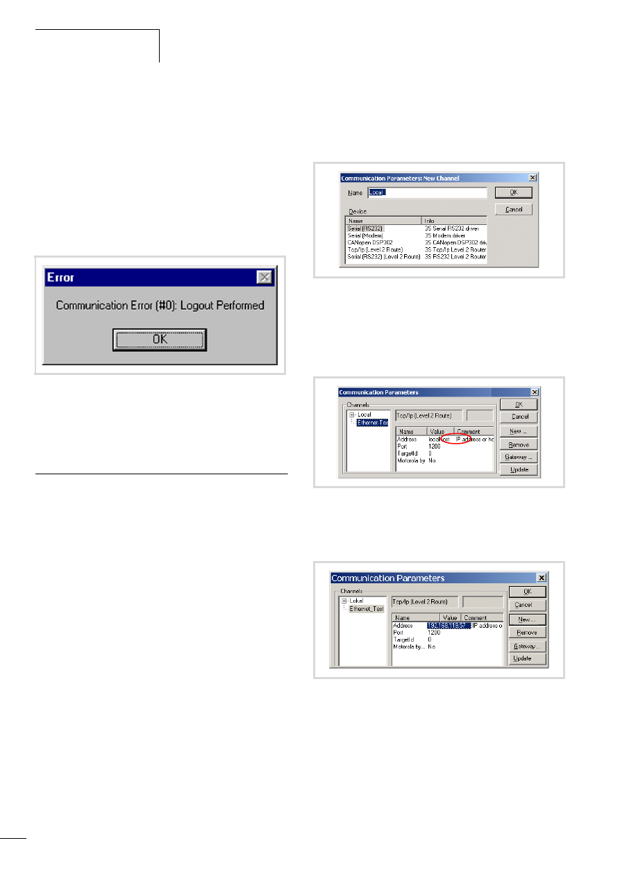
Establishing a PC – MFD4
connection
10/10 MN04802002Z-EN
38
Setting the MFD4 communication parameters
X
Select “PLC Browser” in the “Resources”.
X
Select the “setcomconfig” browser command and add the
required baud rate after inserting a space.
X
Acknowledge the selection with RETURN.
X
Select the “save registry” browser command.
X
Select the “reboot” browser command. After reboot has been
completed, the new baud rate is activated in the MFD4.
Now access the MFD4 (e.g. by a login), you will receive the
following fault message:
In order to communicate with the MFD4, you must adapt the
communication settings of the PC, a section „Setting the PC
communication parameters“.
Connection set-up via Ethernet
After you have connected the PC to the MFD4 with a cable, select
the TCP/IP communication channel in the programming software
and enter the IP address of the MFD4. The MFD4 has the default
address 192.168.119.57.
The selection of the data transfer rate of the Ethernet connection
is performed in Autosensing (detect) mode. Components with this
feature automatically recognise if it is a 10 or 100 MBit/s
connection.
Selecting communication channel and address
X
Access the menu with ‹Online l Communication parameters›.
X
Push the “New…” button.
X
Select the overview of the communication channel TCP/IP
(Level2Route) and change the name “local”e.g. to
“Ethernet-Test”
X
Confirm with OK.
X
Perform a double click on the “localhost” field and enter the
default address 192.168.119.57
X
Confirm your details, by first pressing on another field and then
on OK.
X
Compile the program and log out.
Figure 52: Communications fault
Figure 53: Channel selection
Figure 54: Enter the IP address
Figure 55: Communication parameters with IP address
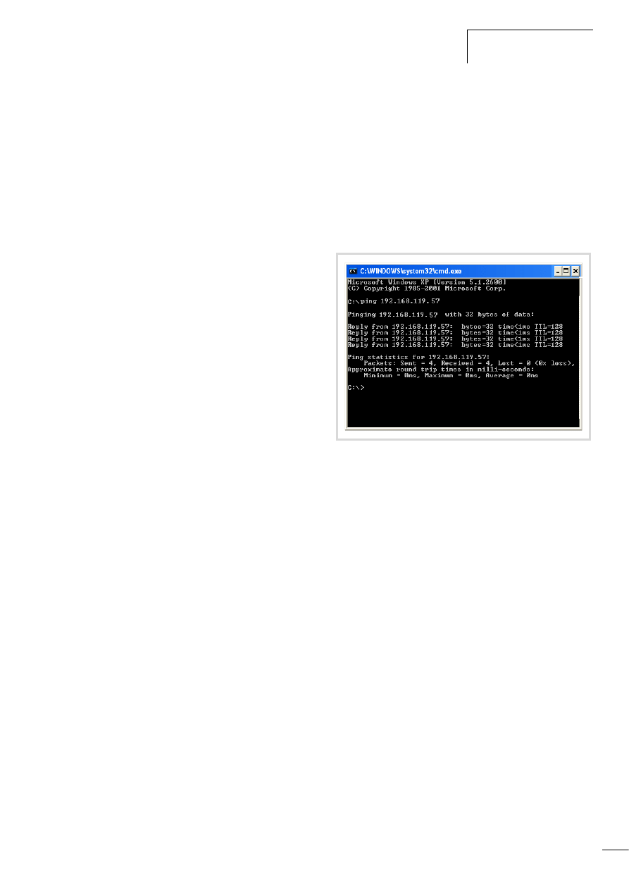
10/10 MN04802002Z-EN
Connection set-up via Ethernet
39
Scan/Modify the IP address
The “setipconfig” and “getipconfig” browser commands are
available for modifying and scanning the IP address a section
„Browser commands“ on Page 57.
Restart the MFD4 after you have changed the IP address.
The DHCP function (Dynamic Host Configuration Protocol) is not
activated.
Ensure that the IP address of the programming device belongs to
the same address family. This means, the IP address of the
programming device and the MFD4 must correspond in the
following number groups:
Example 1
IP address MFD4:
192.168.119.xxx
IP address PC:
192.168.119.yyy
Example 2
IP address MFD4:
192.168.100.xxx
IP address PC:
192.168.100.yyy
The following conditions apply in example 1 and 2:
• xxx is not equal to yyy
• the addresses must be between the limits 1 and 254.
• The addresses must be part of the same address family.
If a connection is not established, the transfer route can be
checked with the “PING” function in order to ensure that the
connection has not failed due to a fault on the transmission path.
The following steps are necessary:
X
Open the DOS window via the “Start” field and the “Run”
command.
X
Enter “CMD” in the input field and confirm with “OK”.
You are presented with a window indicating a drive and a flashing
cursor behind the drive designator.
X
For the example mentioned you would enter the following text:
“ping 192.168.119.57” and confirm this with “OK”.
If the routing is functioning correctly, you will receive a response
indicating the response time. Otherwise a time-out will indicate
problems with the connection set-up.
The following figure indicates the result of a correct connection
set-up.
Figure 56: PING response with a correctly established Ethernet
connection

10/10 MN04802002Z-EN
40

10/10 MN04802002Z-EN
41
8 Defining the system parameters via the STARTUP.INI file
Overview
System parameters independent of the project can be set by you
and saved on the memory card. Here they are contained in the
Startup.INI file. The memory card can also be plugged into other
devices. The device accepts the parameters when started. The
Startup.INI file is always created with all the device-specific
settings (a table 7).
Parameters in the Startup.INI file
Some parameters, such as the Baud rate of the COM interface
have already been entered by the system, to ensure that
communication can take place between the PC and the device.
The parameters can be adjusted later.
Table 7:
Predefined default parameters in the Startup.INI
Table 8:
Example: contents of the STARTUP.INI file
Structure of the INI file
An INI file is a text file with a fixed data format. The system
parameters are listed from a specified section such as [STARTUP],
followed by an equals sign and the corresponding value. The line
is terminated with CR/LF (Carriage/Return).
Lines commencing with a semicolon are interpreted by the device
as comments and are ignored:
The parameters can be changed or created with a text editor if you
insert the memory card into the memory card slot of a PC. The file
STARTUP.INI is saved on the memory card in the directory
“MOELLER/MFD57/PROJECT/”.
Creating the Startup.INI file
Generally the device operates when first activated (initial state)
with default system parameters, the STARTUP data regardless of
whether the device contains a project or boot project! If you load
the project into the device which is in the initial state, the device
will immediately start to operate with the parameters of the
project.
With the browser command “createstartupini” you will transfer
from the device either the STARTUP data – or if it contains a
project – the system parameters onto the memory card.
This creates the Startup.INI file which contains this data.
Precondition: the memory card must be plugged in, formatted and
empty, i.e. without Startup.ini file.
A file which already exists cannot be changed or overwritten by
the browser command “createstartupini”. If you still enter the
command, a warning appears. In order to create a new file the
existing file must be deleted first. a section „Deleting the
Startup.INI file“ on Page 42.
TARGET=MFD4-5-XRC-30
HOST_NAME=NoNameSet
IP_ADDRESS=192.168.119.57
IP_SUBNETMASK=255.255.255.0
COM_BAUDRATE=38400
CAN_ROUTING_CHANNEL=1
[STARTUP]
TARGET=MFD4-5-XRC-30
to the Ethernet connection:
HOST_NAME=NoNameSet
IP_ADDRESS=192.168.119.57
IP_SUBNETMASK=255.255.255.0
IP_GATEWAY=
IP_DNS=
IP_WINS=
to the programming interface RS232:
COM_BAUDRATE=4800, 9600, 19200, 38400, 57600
to the CAN interface:
CAN1_BAUDRATE: 10,20,50,100,125,250,500
CAN1_NODEID=1-127
CAN_ROUTEID=1-127
CAN_ROUTING_CHANNEL=1
COM1_BAUDRATE=38400
(Carriage/Return)
; CAN_NODEID=2
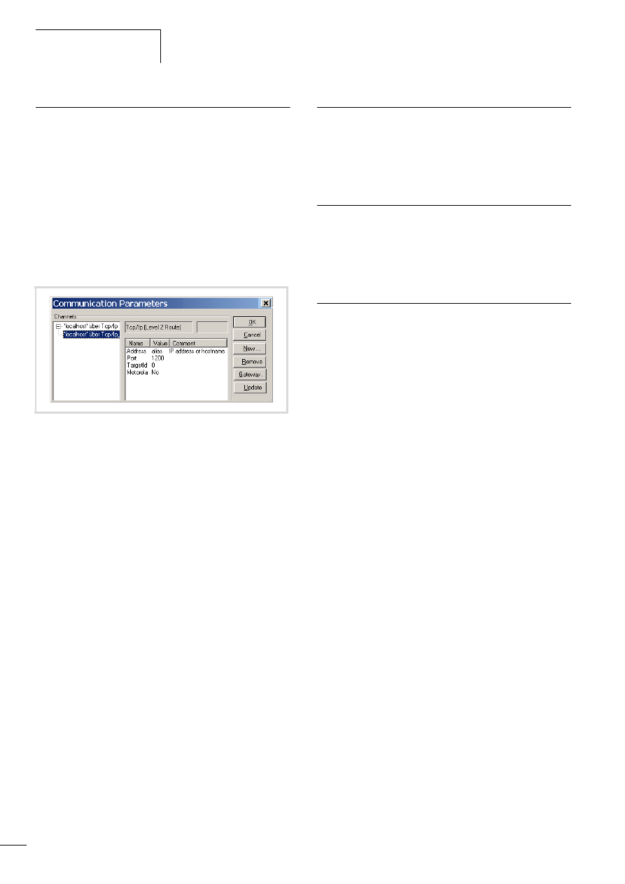
Defining the system
parameters via the
STARTUP.INI file
10/10 MN04802002Z-EN
42
Entry of the INI file: “HOST_NAME”
With the help of the parameter “Device name (HOST_NAME)” the
PLC can be contacted via the Ethernet with this device name.
Furthermore, it can also be contacted with its IP address.
It receives the “NoNameSet” entry from the system. If it is not
changed the device connected to the Ethernet can be contacted
via its IP address. Using the browser command “settargetname
...” you enter a new device name. The device name must be
unique for each device. It can also be used as a communication
parameter (in the figure 57: alias) if it is defined in the
programming software in the menu ‹Online l Communication
parameter›. The parameters define the properties of the
programming connection between PC and device.
The device name can be read with the browser command
“gettargetname”.
Switching on the controller with the fitted memory card
containing the Startup.INI file
When the controller is started up, the data from the Startup.INI file
on the memory card is transferred to the controller. These system
parameters are also active after a new program is loaded.
Changing parameters
The parameters are retained until you enter the browser command
“removestartupini” and then switch the controller off and on
again. The device now operates with the parameters of the
project.
Deleting the Startup.INI file
The following Browser commands are available for deleting.
• removestartupini:
Always deletes the system parameters in the device. If a
memory card is plugged in, the INI file on the memory card is
deleted. The parameters from the project is accepted next time
the device is switched on.
• removeprojfrommmc:
Deletes the boot project and the INI file on the memory card.
The system parameters in the device are retained.
The behaviour of the Startup.ini file with the Hard Reset menu
command and the “factoryset” browser command is described in
section “Reset”on Page 25.
If you execute the “Full reset” command in online mode, the
operating system and the project on the Disk_sys are deleted. The
STARTUP.INI file is retained.
Figure 57: Communication parameters
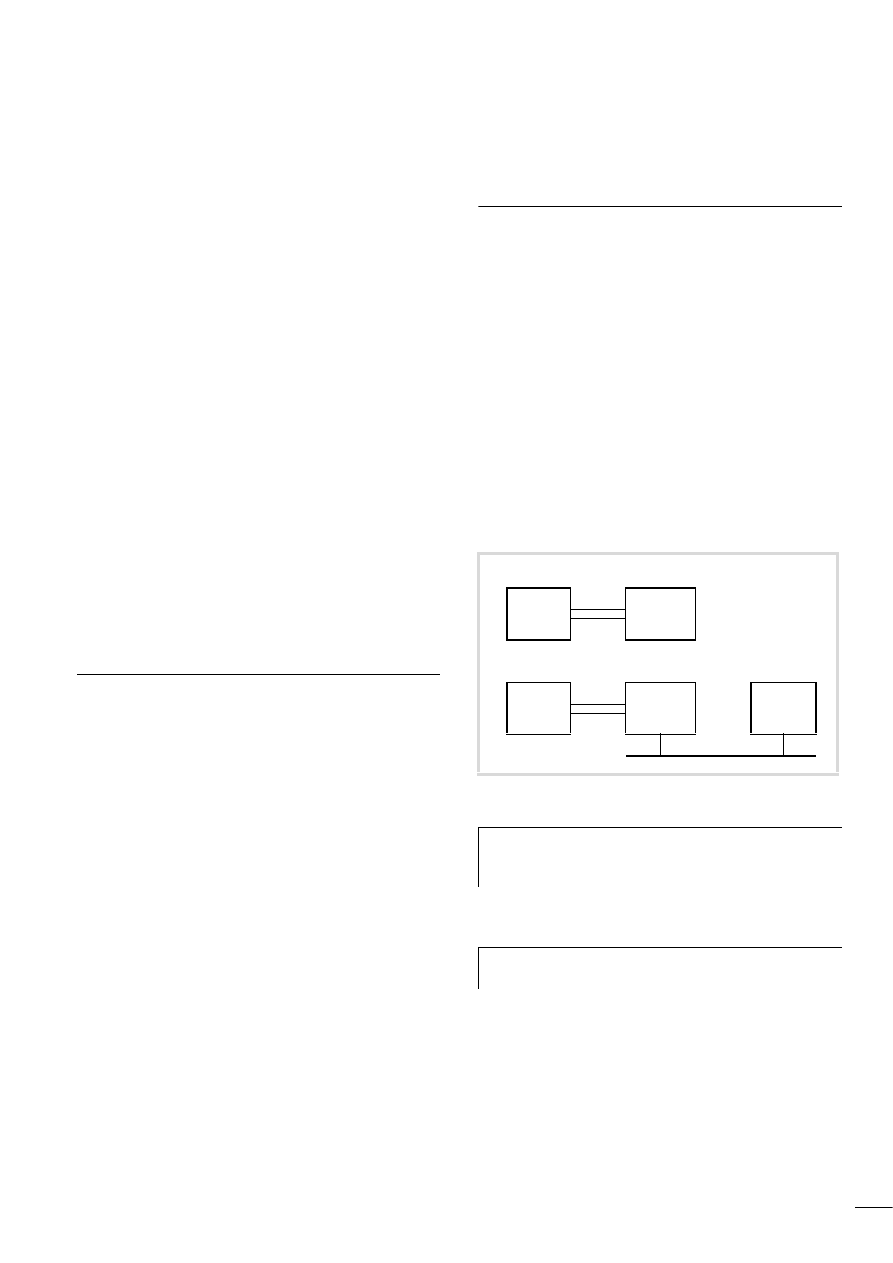
10/10 MN04802002Z-EN
43
9 Programming via the CANopen network (routing)
“Routing” is the capability to establish an Online connection from
a programming device (PC) to any desired (routing capable)
station in a CAN network, without having to directly connect the
programming device with the target station. All actions can be
implemented using the routing connection, which is available
between the programming device and the station with a direct
Online connection:
• Program download
• Online modifications
• Program test (Debugging)
• Generation of boot projects
• Write files to the station
• Read files from the station
Routing offers the advantage of being able to access all routing
capable stations from a station connected with the programming
device. You determine in the project selection in the programming
software which station you wish to communicate with. This makes
it possible to operate remotely configured stations easily.
However, the data transfer from routing connections is
significantly slower than with direct (serial or TCP/IP) connections.
This results, for example, in slower display refresh rates of
variables and longer download times.
Requirements
The following prerequisites must be fulfilled to use routing:
• Both the routing station and the target station support routing.
• Both stations are connected via the bus.
• The stations must both have the same active baud rate.
• Both stations must have a valid routing node ID.
Routing properties of the MFD4
Routing can be implemented without prior download of a user
program (default: 125 kBaud, Node-Id 127). For this the target
station does not have to be configured as a master or device.
For example, you can load a program from the PC via a station to
the MFD4. For this assign a routing node ID to the MFD4 (target
station).
Optimising TCP/IP data transfer
If you select a TCP/IP connection between the PC and MFD4, you
must adapt the size of the data blocks of the transfer type
(program transfer or routing). The block size for fast program
transfer to the MFD4 is 128 Kbyte (default setting). This is also
possible with a block size of 4 Kbyte (somewhat slower). If you are
routing via the MFD4 to the target station, the block size must be
set to 4 Kbyte.
Setting the size of the data blocks
X
Close all applications.
X
Close the CoDeSys gateway server.
Figure 58: Optimising TCP/IP data transfer
h
If a program download is performed, the progress bar on
the programming device monitor will only change
erratically (about every 10 seconds).
h
You can change this setting only if you have administrator
rights on your PC.
Transfer
PC
TCP/IP
MFD4
Transfer/Routing
PC
TCP/IP
MFD4
Target
station
CAN
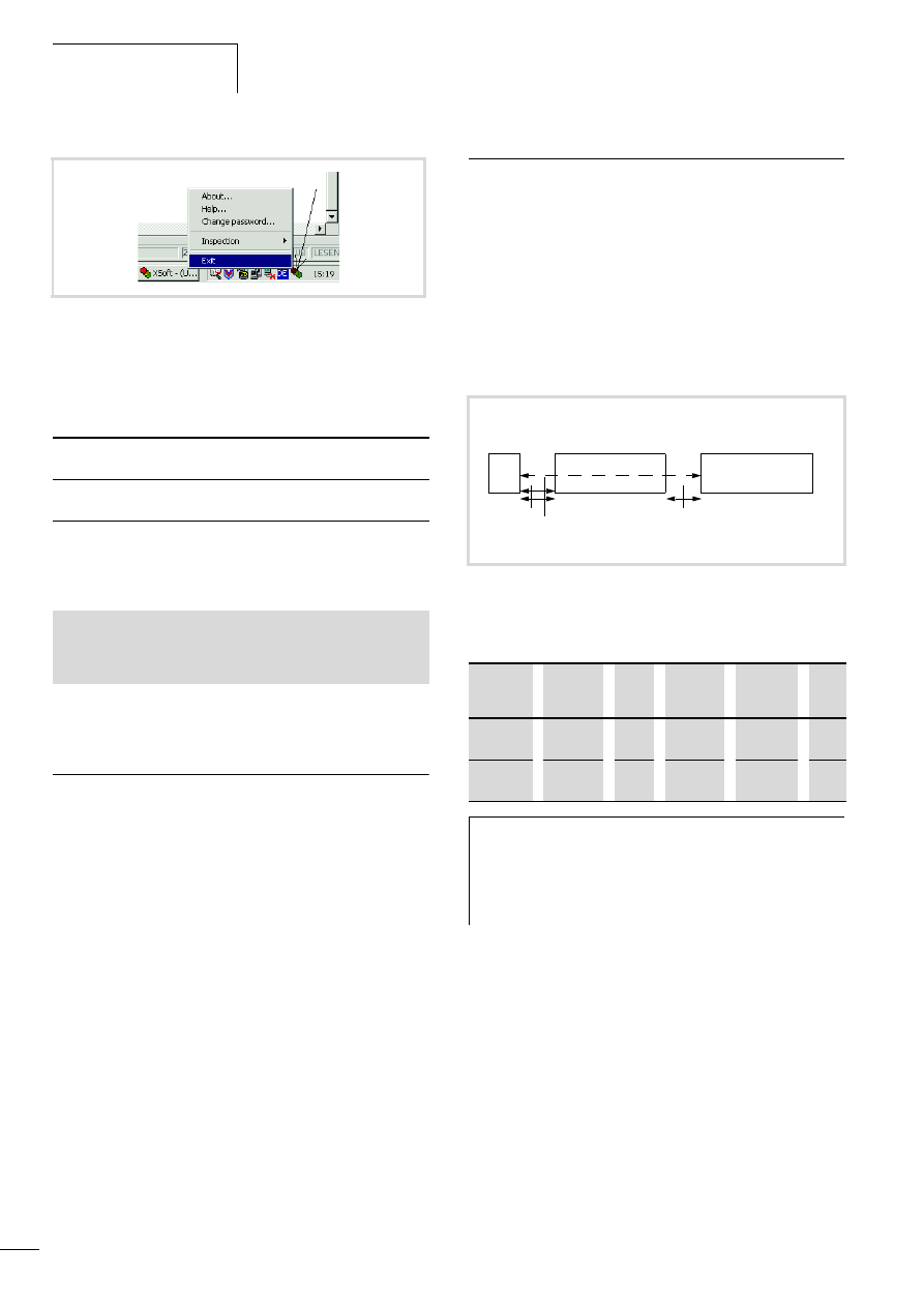
Programming via the CANopen
network (routing)
10/10 MN04802002Z-EN
44
X
Change the block size to the required value.
The following *.reg files are available in the installation directory
to enter the block size in the registry:
Alternatively, you can use the BlockSizeEditor application to
change the block size.
The download block size is defined in the following Registry key:
The default block size is 20000
hex
(= 28 Kbyte), the block size for
routing is 1000
hex
(= 4 Kbyte).
Notes
• If larger files are written to the target station or read from the
station, the online connection may be interrupted after the
transfer. Renewed connection is possible.
• If a program with a modified routing Node ID is loaded into the
target station via a routing station, the target station accepts
the modified routing Node ID; however, the communication
connection will be interrupted. Reconnection with a corrected
routing Node ID is possible.
• A station cannot be accessed via a routing connection if it
contains a program without any valid routing parameters
(Baud rate/Node ID). The parameters may for example have
been deleted by a HARD RESET, if the PC with the programming
software was directly connected to the target station.
The parameters are retained if the HARD RESET is carried out via
the routing station.
• The routing is independent of the configuration
(Master/Device): it is possible to access a target station which
has not been configured as a master or as a device. It must only
receive the basic parameters such as node ID and baud rate, as
well as a simple program.
Setting the node ID/routing ID
Stations on the CANopen bus can be configured as a master or as
a device. The controllers are assigned a Node ID/node number
(address) so that they can be identified uniquely (for the basic
communication). If you wish to use the routing function to access
a target station, you must assign another routing ID to the routing
and the target station. For example, the MFD4 or the faster
Ethernet interface can be used as connection between the PC and
RS232.
In the following example, the routing station is of type Master and
the target station is of type Device.
Table 9:
Example for setting the Node Id, routing ID, Baud rate
Figure 59:Closing the CoDeSys gateway server
BlockSizeDefault.reg
Enters a block size of 20000
hex
= 128 KByte
(default value) in the Registry.
BlockSizeRout.reg
Enters a block size of 1000
hex
= 4 KByte in
the Registry.
[HKEY_LOCAL_MACHINE\SOFTWARE\3S-Smart Software Solutions
GmbH\Gateway Server\Drivers\Standard\Settings\Tcp/Ip (Level
2 Route)]
“Blocksize“=dword:00020000
Figure 60: Routing via ID1=> XC…, EC4-200 or MFD4
a Ethernet connection possible with XC200, MFD4 and EC4--222
Stations
Function
Node
ID
Routing
ID
Baud
rate
a
Fig.
Routing
station
Master
1
127
125 kB
Target
station
Device
3
54
125 kB
h
The following applies to device stations: The Routing-ID
must not be equal to the Node-ID (Basic
communication)!
The exception is the XC100 with operating system
f V2.0: the Routing-ID must be equal to the Node-ID!
PC
Routing station
(Master)
Target station
(Device)
Node-ID: 1
Routing ID: k
Routing-ID n
Node-ID m
k, n, m = 2…127
RS232
Ethernet a
CAN/CANopen
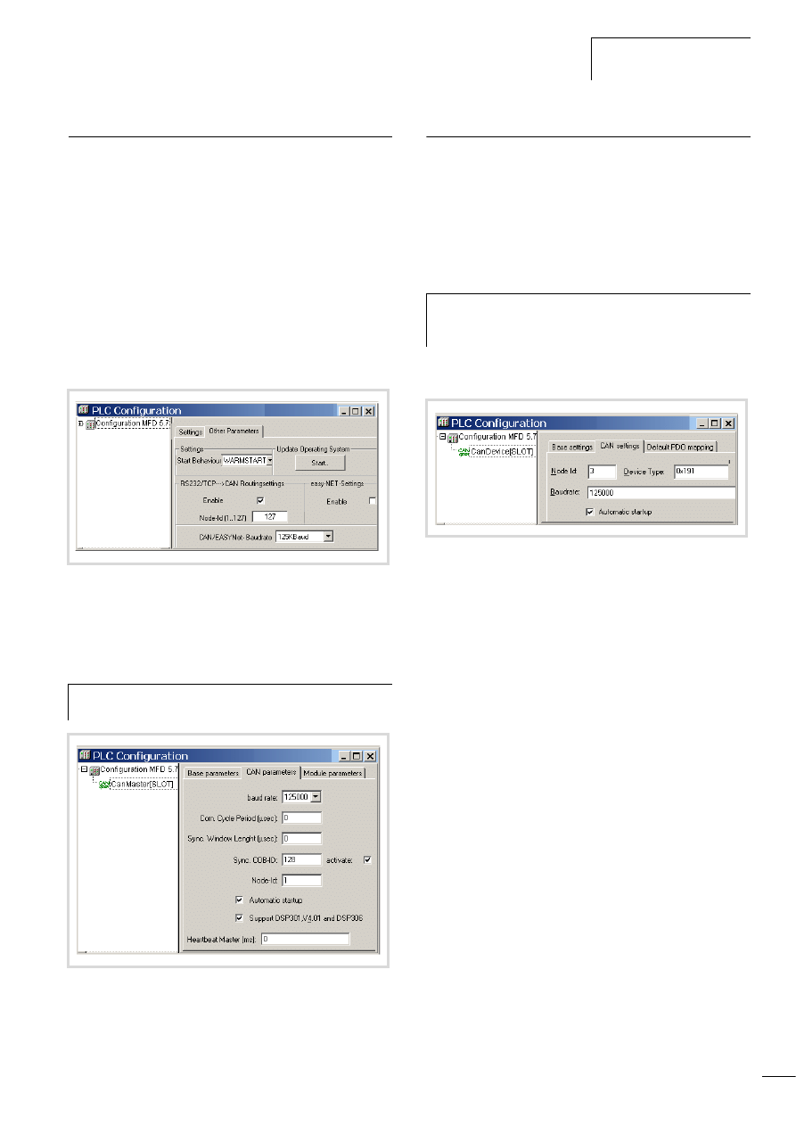
10/10 MN04802002Z-EN
Setting the master station
45
Setting the master station
Define two node IDs in the master station:
• One ID for routing
• One ID for basic communication
Define ID for the routing function:
X
In the PLC configuration set the routing ID and the CAN baud
rate in the Other Parameters tab, a figure 61.
– First click the Enable check box in the RS232/TCP l CAN
routing settings field. The activation is required so that the
station can communicate with the bus.
– Then enter the routing ID/node number and the baud rate on
the bus in the appropriate entry fields.
Define ID for basic communication
X
The ID for basic communication is defined in the “CanMaster”
folder in the “CAN parameters” tab (figure 62).
Setting device (target) station
You assign two node IDs to the device (target) station:
• One ID for routing
• One ID for basic communication
Define the routing ID and the CAN baud rate of the target stations,
e.g. MFD4, in the station configuration in the Other parameters
window, a figure 61.
The ID for basic communication is defined in the “CanDevice”
folder in the “CAN setting” tab, a figure 63.
ID and baud rate are transferred to the stations with the project
download.
Figure 61: Routing settings for master and device
h
Caution!
The baud rate for master and device must be identical.
Figure 62: CAN Master: Node ID for basic communication
h
To guarantee a fast data transfer, the routing should be
performed only with a CAN baud rate of at least
125 KBit/s.
Figure 63:CAN-Deviceparameter
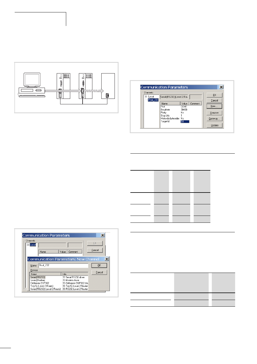
Programming via the CANopen
network (routing)
10/10 MN04802002Z-EN
46
Example
The following example shows the access to the program of a
station.
You have connected the PC to the PLC with node ID “2” and want
to access the target station with routing ID “54”.
X
Open the project of the target station with the program you
wish to edit or test.
X
First configure the parameters for the hardware connection
PC n PLC (Node ID 2).
X
From the Online menu select Communication Parameters.
X
Click the New button under “local” channels.
The “New Channel” window appears.
X
Select the channel in the “Device” window:
Serial [RS232] [Level 2 Route] or TCP/IP [Level 2 Route].
X
In the Name field you can assign a new name, e.g. “Rout_232”.
You have now determined the parameters for the hardware
connection between the PC and the PLC (node ID 2).
X
Enter the target ID of the target station, number 54 in the
example. The target ID is identical to the routing ID! To enter
the target ID, click the field in the Value column to the right of
the term Target ID. Enter there the number 54 and confirm with
OK.
X
Log on and carry out the action.
Station combinations for routing
The following stations support routing:
Number of communication channels
Several communication channels can be opened, e.g. PC n station
2, PC n station 3 depending on the station (communication
channel) which is connected to the PC. In this way, the status
display of the stations 2 and 3 can be carried out at the same time.
Table 10: Type and number of communication channels
Figure 64: Diagnostics possibilities
a XC100 with Node ID 1
b XC200 (MFD4 also possible) with node ID 2, routing ID 127
c Station (e.g. XC..., EC4-200, MFD4) with the node ID 3 and routing
ID 54
Figure 65:Channel parameter setting
a
b
c
CAN
Figure 66: Setting the target ID of the target PLC
From
P
XC100
XC121
XC200
MFD4
EC4-200
To
O
XC100,
XC121
x
x
x
XC200
MFD4
x
x
x
EC4-200
x
x
x
Communications
channel
Stations
Max.
channel
number
TCP/IP Level2Route
XC200/MFD4
5
Serial RS232 Level2Route
XC.../EC4-200/MFD4
1
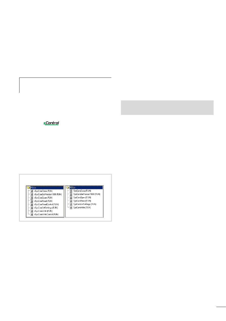
10/10 MN04802002Z-EN
47
10 RS232 interface in Transparent mode
In Transparent mode, data is exchanged between the MFD4 and
data terminal devices (e.g. terminals, printers, PCs, measuring
devices) without any interpretation of the data. For this the RS232
serial interface (COM1) must be switched to Transparent mode via
the user program.
Character formats in Transparent mode are: 8E1, 8O1, 8N1, 8N2.
The libraries xSysCom200.lib or SysLibCom.lib provide functions
for handling the data. Only one of the two libraries can be
incorporated in the Library Manager. The SysLibCom.lib library
was introduced in order to ensure compatibility between the
MFD4 and other
devices.
Both libraries contain functions for opening and closing the
interface, for sending and receiving the data and for setting the
interface parameters. The data types of the libraries are not
identical. The baud rate selection differs:
• xSysCom200.lib:
300, … ,15200
• SysLibCom.lib:
4800, … ,15200
For a better overview, the functions of the libraries are shown next
to each other in figure 67.
The RS232 interface is addressed via the operating system.
The execution of the interface functions can therefore take up to
50 ms. The task, in which the RS232 interface is contacted should
have an interval time of at least 50 ms and be assigned with a low
priority (high value) in multitasking mode, so that time critical
tasks are not hindered.
With the functions (x)SysComRead/Write, only the parts of the
required data length are processed. For complete transfer of data
blocks, repeated calls with matched offset values are to be
executed in multiple task intervals. The number of calls required
depends on the baud rate and quantities of data involved!
The performance of COM1 depends on the load on the PLC
(PLCLoad) and on the selected baud rate. They may be hindered by
time-critical tasks due to the high interval times of the COM1 task.
Character loss is possible when data is received with high baud
rates.
The control cables of the interface are not supported by the
software.
The individual functions are described in the online documentation
“XSoft Function Blocks” (h1456g.pdf).
h
Programming via the RS232 interface is not possible if it
is in Transparent mode. However, the program can be
tested via the Ethernet interface.
xSysCom200.lib
SysLibCom.lib
Figure 67: Function overview
See also:
• Transparent mode: Text output via RS232 (example)
• RS232

10/10 MN04802002Z-EN
48
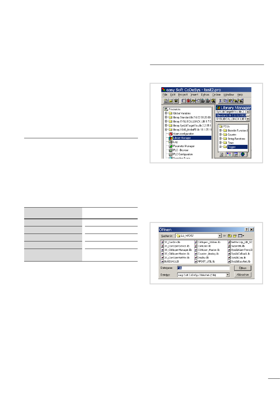
10/10 MN04802002Z-EN
49
11 Libraries, function blocks and functions
The libraries contain IEC function blocks and functions that you
can use, for example, for the following tasks:
• Data exchange through the CANopen bus
• Controlling the real-time clock
• Determining bus load of the CANopen bus
• Sending/receiving data via the interfaces
The libraries are located in the following folders:
• Lib_Common for all devices
• Lib_MFD57 for the MFD4.
Using libraries
When you open a project, libraries Standard.lib and
SYSLIBCALLBACK.lib are copied to the Library Manager.
If you need further libraries for your application, you have to install
these manually.
The libraries in the Library Manager are assigned to the project
after saving. When you open the project, the libraries are then
automatically called up as well.
The following overview lists the documents in which the function
blocks and functions are described.
Installing additional system libraries
You can install libraries manually as follows:
X
In your project, click the “Resources” tab in the object
organiser.
X
Double-click the “Library Manager” element.
X
Click on the menu ‹Insert l Additional Library... Ins›.
The new window will show the libraries available, depending on
the target system.
X
Select the library to install and click Open.
The library now appears in the Library Manager.
Library
Online document
1)
Standard.lib
h1437g.pdf
MFD57_Util. Lib
SysLib… . lib
Online help or PDF files
XS40_MoellerFB. Lib/ Visu. Lib/…
h1456g.pdf
CANUserLib. Lib
CANUser_Master. Lib
h1554g.pdf
1) Further information on finding the files
Figure 68:Libraries, installing manually
Figure 69:Selecting a library
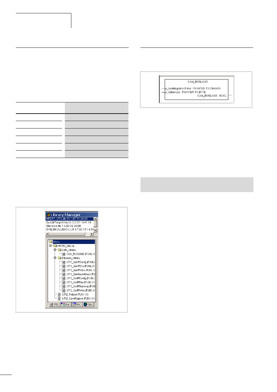
Libraries, function blocks and
functions
10/10 MN04802002Z-EN
50
MFD specific functions
The specific functions are contained in the libraries Display.lib and
MFD57_UTIL.lib.
Display.lib
The functions of the library allow you to change the properties of
the display.
MFD57_Util.
The functions of the library are divided into the following groups:
• CAN utilities, a page 50
• Ethernet utilities, a page 51
• General functions, a page 55.
CAN utilities
The CAN_BUSLOAD function is provided in the library
MFD57_Util.lib in the CAN_Utilities folder.
This function can be called cyclically in a user program. If a read
cycle has been ended successfully, the function returns with TRUE
and writes the determined values for the integration time and the
bus loading to the transferred addresses.
If the calculation of the bus load is not yet completed or the CAN
controller is not yet initialised, the function returns with the FALSE
function as a return value.
A read cycle is 500 ms long.
Function
Description
DIS_GetBackLight
Back-lighting
DIS_GetContrast
Read contrast values
SetBackLight
Set Back-lighting
DIS_SetContrast
Set contrast values
DIS_CalibrateTouch
Calibrate MFD4
DIS_GetSupplierVersion
Read library version
Figure 70: Specific functions of the MFD57-UTIL.lib library
Figure 71: Function CAN_BUSLOAD
See also:
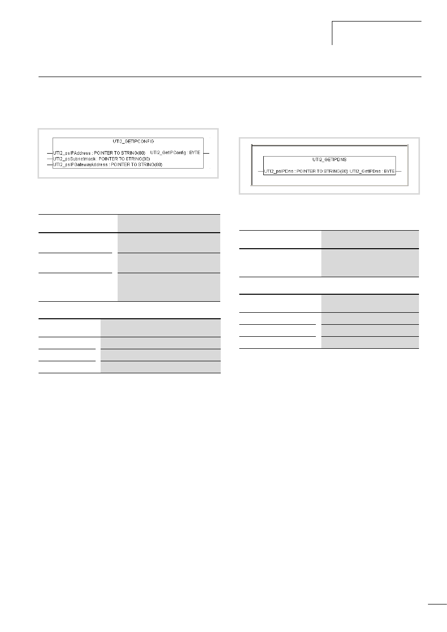
10/10 MN04802002Z-EN
Ethernet utilities
51
Ethernet utilities
UTI2_GetIPConfig
Get IP, subnet mask and IPGateway address
Table 11: Input variables
Table 12: Return value
UTI2_GetIPDNS
Display IP address of the dynamic name server set on the
MFD4
Table 13: Input variables
Table 14: Return value
Figure 72: UTI2_GetIPConfig
Input variables
Meaning
UTI2_psIPAddress:
Pointer to a string in which the read IP
address is written.
UTI2_psSubnetmask:
Pointer to a string in which the read
address of the subnet mask is written.
UTI2_psIPGatewayAddress:
Pointer to a string in which the read
address of the standard gateway is
written.
Return value
Meaning
1
Read successful.
<0
Read fault (general fault)
-4
No valid pointer transferred.
Figure 73: UTI2_GETIPDNS
Input variables
Meaning
UTI2_psIPDns
Pointer to a string variable, in which
the address of the dynamic name
server is entered.
Return value
Meaning
1
Read successful.
<0
Read failed (general fault).
-4
No valid pointer transferred.
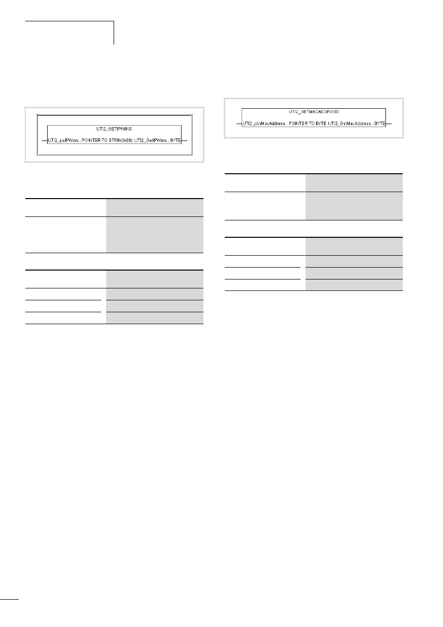
Libraries, function blocks and
functions
10/10 MN04802002Z-EN
52
UTI2_GetIPWINS
Display IP address of the Windows name server set on the
MFD4
Table 15: Input variables
Table 16: Return value
UTI2_GetMacAddress
Get MAC address (MAC=Media Access Control)
Table 17: Input variables
Table 18: Return value
Figure 74: UTI2_GETIPWINS
Input variables
Meaning
UTI2_psIPWins
Pointer to a string variable, in which
the address of the dynamic name
server is entered. (Netbios Name
Server)
Return value
Meaning
1
Read successful.
<0
Read failed (general fault).
-4
No valid pointer transferred.
Figure 75: UTI2_GetMacAddress
Input variables
Meaning
UTI2_pbyMacAddress
Pointer to an array of 5 byte values, in
which the read MAC address is
entered.
Return value
Meaning
1
Read successful.
<0
Read failed (general fault).
-4
No valid pointer transferred.

10/10 MN04802002Z-EN
Ethernet utilities
53
UTI2_SetIPConfig
Setting the IP- and subnet mask address
Table 19: Input variables
Table 20: Return value
UTI2_SetIPDNS
Change the IP address of the dynamic name server on the
MFD4
Table 21: Input variables
Table 22: Return value
Figure 76: UTI2_SetIPConfig
h
Caution!
A newly entered value must be saved as a non-volatile
value by a “SaveRegistry” or a “Reboot” command. The
newly entered value is accepted only after a restart of the
device.
Input variables
Meaning
UTI2_psIPAddress
Pointer to a string variable which contains the
IP address to be written.
UTI2_psSubnetmask
Pointer to a string variable, which contains
the value to be entered from the subnet
mask.
Return value
Meaning
1
Write successful.
<0
Write failed (general fault).
-4
No valid pointer transferred.
Figure 77: UTI2_SetIPDNS
Input variables
Meaning
UTI2_psIPDns
Pointer to a string variable, which contains the
value to be entered from the dynamic name
server.
Return value
Meaning
1
Write successful.
<0
Write failed (general fault).
-4
No valid pointer transferred.
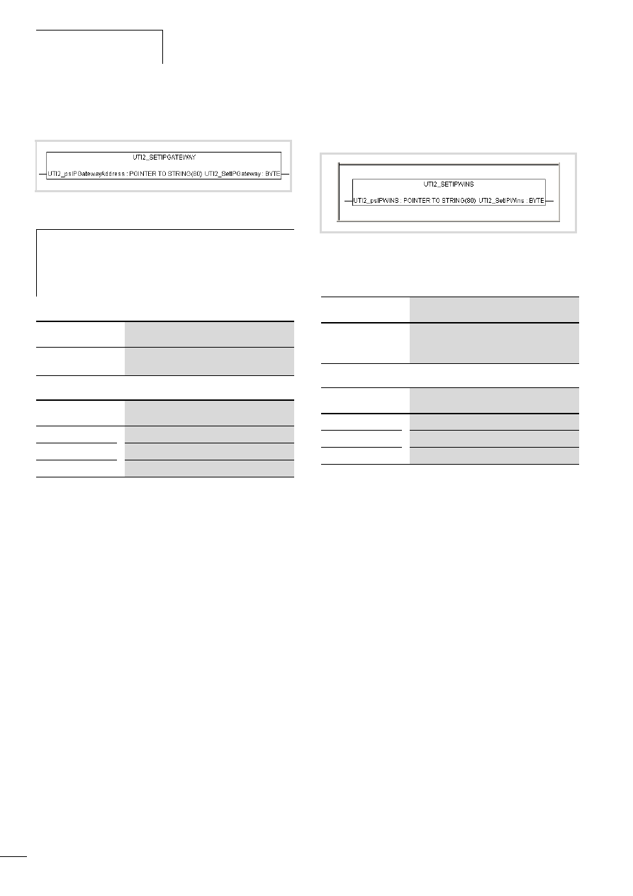
Libraries, function blocks and
functions
10/10 MN04802002Z-EN
54
UTI2_SetIPGateway
Setting of the IP Gateway address
Table 23: Input variables
Table 24: Return value
UTI2_SetIPWINS
Change the IP address of the Windows name server on the
MFD4
Table 25: Input variables
Table 26: Return value
Figure 78: UTI2_SetIPGateway
h
Caution!
A newly entered value must be saved as a non-volatile
value by a “SaveRegistry” or a “Reboot” command. The
newly entered value is accepted only after a restart of the
device.
Input variables
Meaning
UTI2_psIPGatewayA
ddress
Pointer to a string variable, which contains the
value to be entered from the gateway address.
Return value
Meaning
1
Write successful.
<0
Write failed (general fault).
-4
No valid pointer transferred.
Figure 79: UTI2_SetIPWins
Input variables
Meaning
UTI2_psIPWins
Pointer to a string variable, which contains the
value to be entered from the Windows name
server.
Return value
Meaning
1
Write successful.
<0
Write failed (general fault).
-4
No valid pointer transferred.
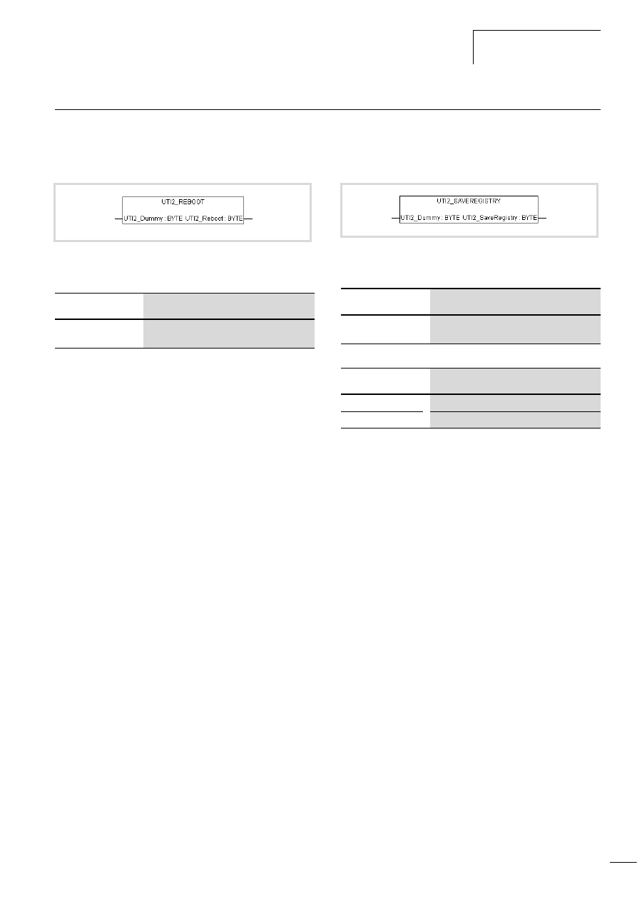
10/10 MN04802002Z-EN
General functions
55
General functions
UTI2_Reboot
Restart with registry storage
Table 27: Input variables
Return value
The value “1” is always returned.
UTI2_SaveRegistry
Saving of the registry
Table 28: Input variables
Table 29: Return value
Figure 80: UTI2_Reboot
Input variables
Meaning
UTI2_Dummy
A dummy byte which is not evaluated in the
function.
Figure 81: UTI2_SaveRegistry
Input variables
Meaning
UTI2_Dummy
A dummy byte which is not evaluated in the
function.
Return value
Meaning
1
Order successfully entered into the job thread.
2
Job could not be entered in the job thread.

10/10 MN04802002Z-EN
56

10/10 MN04802002Z-EN
57
12 Browser commands
The browser is a text-based device (terminal) monitor. Browser
commands can be use to query parameters and the status of the
MFD4. To do this enter the command in the input line and confirm
it with Enter (Return). The response appears in the result window.
This function can be used for diagnostics and debugging purposes.
Communication parameter access
Settings of the communication parameters via Browser commands
such as device names, Ethernet addresses, gateway addresses or
baud rates of the serial interface, are only modified and not
directly accepted/saved in the database entry in Windows-CE
REGISTRY with the following commands.
• setcomconfig
• setipconfig
• setipgateway
• settargetname
With the commands “setcomconfig”, “setipconfig”,
“setipgateway”, “settargetname”, you must add additional
parameters in the command line of the PLC browser, e.g. the Baud
rate with “setcomconfig”, a table 30. Close the line by pressing
RETURN. An answer will be shown in the results window.
The “setipconfig” browser command automatically generates a
“settargetname”. The target name is comprised of a short
description of the target system and the last numeric block of the
IP address, e.g..: MFD57_Nr010.
The target name is automatically generated according to the
IP address and the target system. It can be called via
“gettargetname”.
Calling up browser commands
X
Activate the “Resources” tab in the programming software and
select the “PLC browser” folder.
X
Click at the top right of the window on the button “…”
X
Double-click the required browser command to select it.
Add additional parameters to the command if required, such as
the Baud rate with “setcomconfig”, a table 30.
X
The command may require additional parameters.
X
Press the Return button.
Command overview
The browser commands which are available for the target system
are listed in table 30 alphabetically. They are arranged into two
groups:
• Standard PLC 2.4 browser commands (assigned with a grey
background in the table)
• Target system specific PLC 2.4 browser commands; these
commands are managed in a file and are implemented in the
runtime system.
h
Caution!
Delete the Startup.INI file before executing one of these
commands, a chapter „Defining the system parameters
via the STARTUP.INI file“ on Page 41.
After one of these browser commands has been executed,
saving of the REGISTRY is necessary. The following
Browser commands are available for this purpose.
• saveregistry (saves the registry) + reboot
• shutdown (saves the registry and waits for “voltage
off”)
• reboot (saves the registry and generates a software
reset)

Browser commands
10/10 MN04802002Z-EN
58
Table 30: Browser commands
Command
Description
a
Page
?
Get a list of implemented commends
calibratetouch
User interface for display calibration
canload
Display of the loading of the CANopen fieldbus
clearerrorlist
Erase error list
cleareventlist
Erase event list
copyprojtommc
1)
Copy the (boot) project onto a Multi Media Card (incl. directory structure/project directory)
createstartupini
Create the Startupini file on the disk_sys and disk_mmc
delpwd
Erase password for online access
dpt
Output data pointer table
easynetconfig
2)
Configuration, transfer of parameters to the easyNet nodes (does not change the NET ID)
easynetconfigforce
2)
Configuration, transfer of parameters to the easyNet nodes (changes the NET ID)
filecopy
1)
Copy file
filedelete
1)
Erase file
filedir
1)
Directory list [First folder in the list]
filerename
1)
Rename file
getbacklight
Show the display's backlight value
getbattery
Display battery status
getcomconfig
Display baud rate of serial interface 1
getcontrast
Show the display's contrast value (only for STN displays)
geterrorlist
Display error list
geteventlist
Display event list
getipconfig
Display Ethernet address
getipdns
Display current DNS address
getipgateway
Display Gateway address
getipwins
Display current WINS address
getlanguage
Display dialog language for the error list
getmacaddress
Display MAC address [80-80-99-2-x-x]
getprgprop
Read program information
getprgstat
Read program status
getrtc
Display data and time [YY:MM:DD] [HH:MM:SS]
getswitchpos
Display status of the operating switch
gettargetname
Display device name
getversion
Display version information
memdisk_sys
Displays the free memory at “disk_sys”
pid
Output project ID
pinf
Output project information
plcload
1)
Display system performance: CPU usage
ppt
Output module pointer table
reboot
Accept changes (registry save) and restart PLC
reflect
1)
Mirror current command line for test purposes.
reload
Reload boot project again
removeprojfrommmc
Removes the backup project from the MMC

10/10 MN04802002Z-EN
Command overview
59
removestartupini
Erases the Startupini file from the disk_sys and disk_mmc
resetprg
Reset user program
resetprgcold
User program cold reset
resetprgorg
Reset user program to original state
restoreretain
Restore retentive data from file [File name]"
saveregistry
Accept modifications
saveretain
Save retentive data in the file [Filename]
setbacklight
Set the display's backlight value
setcomconfig
1)3)
Set the baud rate of the serial interface [setcomconfig4800,9600,19200,38400,57600,115200]
e.g.: setcomconfig 38400
setcontrast
Set the display's contrast value (only for STN displays)
setipconfig
1)3)
Set Ethernet configuration [setipconfig adr1.adr2.adr3.adr4 mask1.mask2.mask3.mask4]
z. B. setipconfig 192.168.119.010 255.255.255.000
setipdns
Set DNS address [setipdns adr1.adr2.adr3.adr4]
setipgateway
1)3)
Set gateway address [adr1.adr2.adr3.adr4]; e.g.: setipgateway 192.168.119.010
setipwins
Set WINS address [setipwins adr1.adr2.adr3.adr4]
setlanguage
Determine dialog language for error list [deu/eng/fra/ita]
setpwd
Activate password for online access
setrtc
1)
Set date and time [YY:MM:DD] [HH:MM:SS]; e.g.setrtc 03:07:24 10:46:33
settargetname
1)3)
Set device name [devicename]; e.g.: settargetname test
shutdown
Accept changes (registry save) and switch off PLC
startprg
Start user program
stopprg
Stop user program
tsk
Output IEC task list with task information
updatefrommmc
Update windows image from /disk_mmc/MOELLER/MFD57/btsmfd57_Vxxxxx.nbk
1) You can call up help with extended information for these Browser commands in the programming software.
Enter a question mark followed by a space before the command e.g.: ? plcload in the command line of the PLC browser
2) 2. Transferring the parameters and assignment of IDs using the NET_CONFIG function. You will find this information in far greater
detail in the manual " Data transfer between easy and IEC PLCs (easyNet)", h1593en.pdf.
3) Observe the section “Communication parameter access”, Page 57.
Command
Description
a
Page
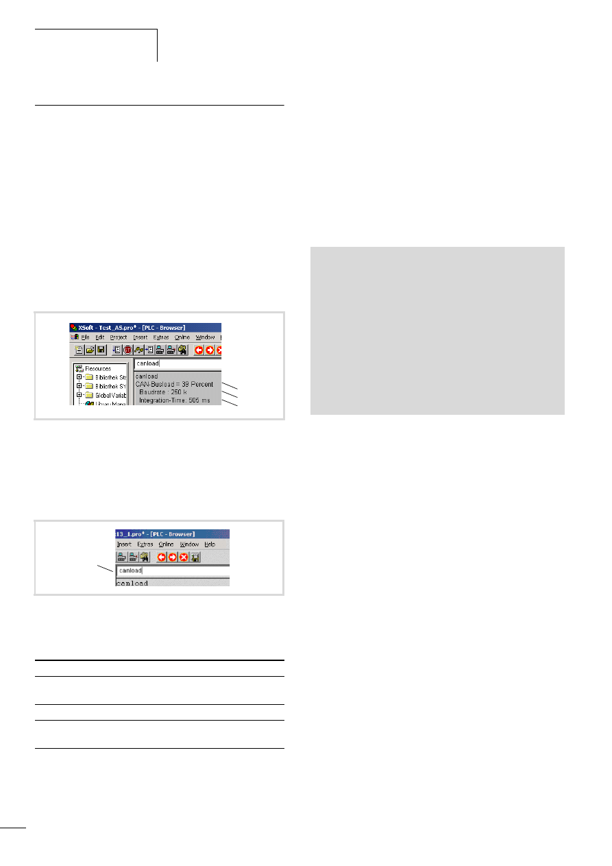
Browser commands
10/10 MN04802002Z-EN
60
Important browser commands
Display CPU loading (plcload)
The “plcload” browser command provides information on the
current system loading of the CPU.
A loading > 95 % can lead to a failure of the serial and Ethernet
communication and/or impairment of the real-time behaviour.
Display the loading of the CAN bus (canload)
The “canload” PLC browser command is part of the
“MFD57_Util.lib” library. It indicates the loading of the CAN bus.
Examples for display:
Table 31: Possible alarm messages
Access to memory objects
These commands have the name of the memory card, the directory
structure and the file names as parameters. Pay close attention to
the respective special characters when entering commands.
• filecopy
• FileRename
• filedelete
• filedir.
Examples:
Figure 82: Loading of the CAN bus (Example 1)
a Loading of the CAN bus in the last integration interval.
b Current baud rate of the CAN bus
c Time via which the loading of the CAN bus has been integrated.
The integration time is set by default to 500 ms and can't be
changed via the browser.
Figure 83: Loading of the CAN bus with alarm message (example 2)
a Alarm message,
Alarm message
Meaning
ATTENTION: HIGH
BUSLOAD
Loading of the CAN bus f 75 %
CAN bus not activated
The CAN bus is not active
CAN-Busload = Invalid
Calculation
Monitoring of the bus load has failed
c
b
a
a
filedir (without parameter details the default setting is:
\\disk_sys\\project)
filedir \\disk_sys
filedir \\disk_sys\\project
filedir \\disk_mmc\\MOELLER\\MFD57
filedir \\disk_mmc\\MOELLER\\MFD57\\project\\aaa.prg
filecopy \\disk_sys\\project\\default.prg
\\disk_sys\\project\\yyy.prg
filerename \\disk_sys\\project\\yyy.prg \\disk_sys\\project\\
xxx.prg
filecopy \\disk_sys\\project\\default.prg \\disk_mmc \\
MOELLER\\MFD57\\project\\default.prg
filedelete \\disk_mmc\\MOELLER\\MFD57\\project\\default.prg
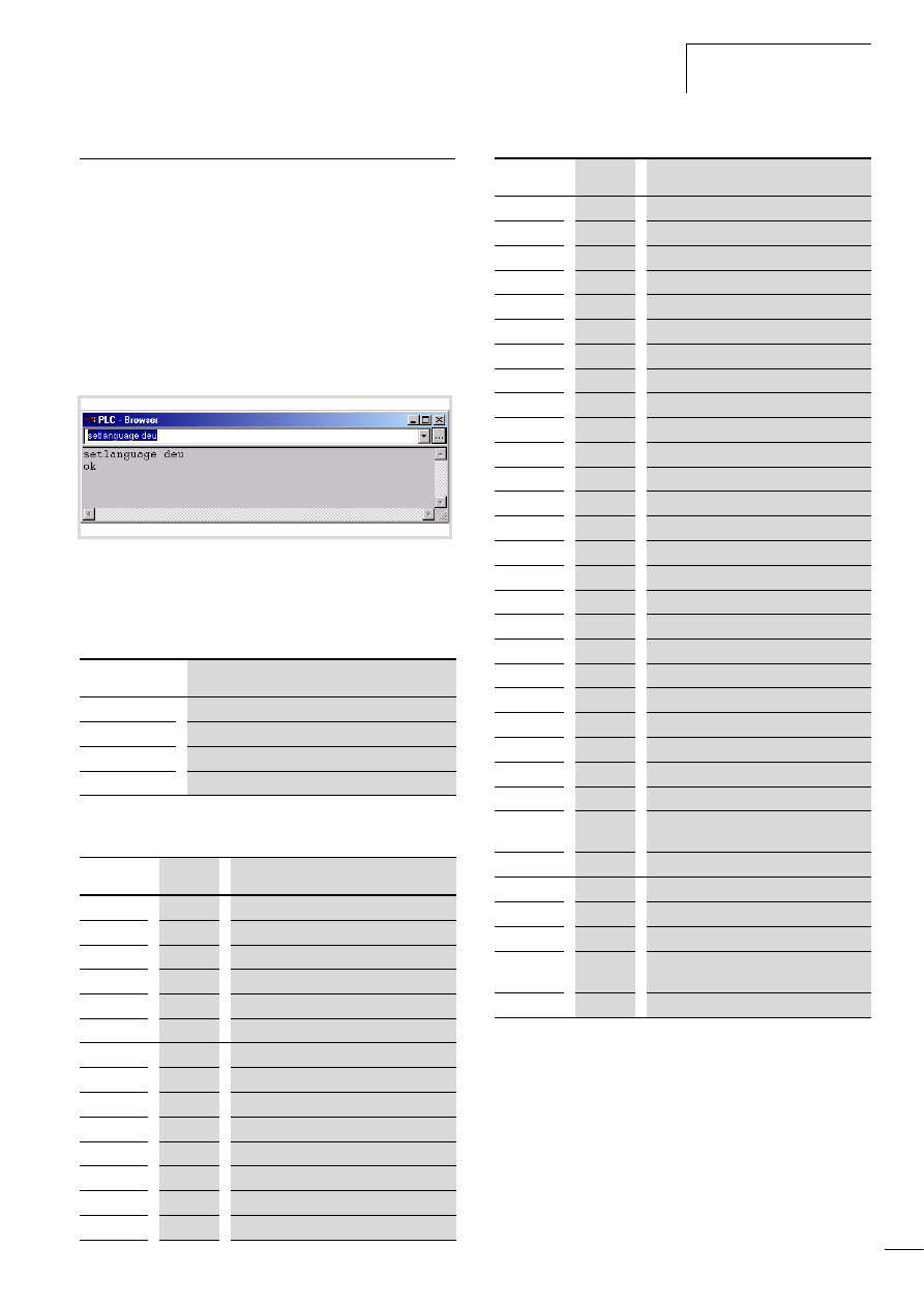
10/10 MN04802002Z-EN
Error and event list after
calling browser commands
61
Error and event list after calling browser commands
The dialog language for error and event lists is available in
German, English, French and Italian.
The active language is displayed with “getlanguage”, the
conversion of the language is implemented with “setlanguage”.
Examples for language conversion:
If the error and event list is to be displayed in German, the
“setlanguage deu” browser command should be entered. The
input is ended with “Return”. You receive the following displayed
window.
The following is an overview of the messages which can occur in
the browser error and event lists. The module ID indicates which
program type the fault signals:
TheEvent-ID defines the fault number of the program. The error
number can start at 0 for every module ID.
Figure 84:Browser command “setlanguage”
Module ID
Program type
1
RTS (runtime system)
2
CST (Eaton specific adaption)
4
CAN
5
IEC
Module ID
Event ID
Error message
2
1
Stop program
2
2
Start program
2
3
Reset warm
2
4
Cold reset
2
5
Reset Hard
2
6
Battery empty
2
7
No program loaded
2
8
Task monitoring
4
10
CAN controller started
4
20
CAN controller stopped
4
30
Overflow
4
31
Overflow
4
40
Overflow
4
41
Overflow
4
42
Overflow
4
50
Critical CAN fault
4
60
CAN controller in status error warning
4
70
CAN controller in status Bus-Off
1
16
Task monitoring fault
1
17
Hardware monitoring fault
1
18
Bus error
1
19
Checksum error
1
20
Fieldbus error
1
21
I/O update fault
1
22
Cycle time exceeded
1
80
Invalid instruction
1
81
Access violation
1
82
Privileged instruction
1
83
Page fault
1
84
Stack overflow
1
85
Invalid scheduling
1
86
Invalid access Identity
1
87
Access on protected page
1
256
Access to uneven address
1
257
Array limit exceeded
1
258
Division by zero
1
259
Overflow
1
260
Exception cant be overlooked
1
336
Floating decimal point: General fault
1
337
Floating decimal point: Not normalised
operand
1
338
Floating decimal point: Division by zero
1
339
Floating decimal point: Inexact result
1
340
Floating decimal point: Invalid instruction
1
341
Floating decimal point: Overflow
1
342
Floating decimal point:
Stack verification error
1
343
Floating decimal point: Underflow
Module ID
Event ID
Error message

10/10 MN04802002Z-EN
62

10/10 MN04802002Z-EN
63
Appendix
Characteristic of the Ethernet cable
Only use the intended cable type for wiring the Ethernet network.
The cable must be at least category “CAT-5” compatible.
“CAT5” cables are suitable for data transfer rates of between 10
and 100 MBit/s.
Table 32: Characteristics of the Ethernet cable
The maximum segment length is 100 meters. If the network is
larger, suitable infrastructure components should be used.
Transceivers, Hubs and Switches are particularly suitable.
The cable to be selected depends on the the ambient conditions at
the installation location (interference, flexibility, transmission
speed).
The installation guidelines for the (Ethernet) wiring are described
in ISO/IEC 11801 and EN50173.
Properties of the CANopen cable
Use only cable approved for CANopen applications and with the
following characteristics:
• Characteristic impedance 100 to 120 O
• Capacitance < 60 pF/m
The demands placed on the cable, connectors and bus termination
resistors are specified in ISO 11898. Following you will find some
demands and stipulations listed for the CANopen network.
In table 34, standard parameters for the CANopen network with
less than 64 CANopen slaves are listed (table complies with the
stipulations of the ISO 11898).
The length of the CANopen bus cable is dependant on the
conductor cross-section and the number of bus users connected.
The following table includes values for the bus length in
dependance on the cross-section and the connected bus users,
which guarantee a secure bus connection (table corresponds with
the stipulations of the ISO 11898).
Table 33: Cable cross-section, bus length and number of bus slaves
conform to ISO 11898
If the bus length is greater than 250 m and/or are more than
64 slaves connected, the ISO 11898 demands a residual ripple of
the supply voltage of 5 %.
UTP
1)
STP
2)
SSTP
3)
Transmission
medium
Unshielded
Twisted Pair
Shielded Twisted Pair
Baud rate
10 MBit/s,
100 MBit/s
10 MBit/s,
100 MBit/s
10 MBit/s,
100 MBit/s
Layout
Stranded every two cores,
without
shield
with full shield
with full
screen, each
core pair is
additionally
screened
Flexibility
Average
Average
Average
Shielding
None
Single
Double
Topology
Point-to-
point
Point-to-point, line, star
Maximum
segment length
100 m
100 m
100 m
1) Use in industrial environments is not recommended due to poor
EMC characteristics.
2) The conductor pairs are shrouded in a full shield. The task of the full
screen is to prevent external interference. This cable is
(conditionally) suitable for industrial use due to the high crosstalk
values between the individual conductor pairs.
3) Unlike the STP cable, this cable has a separate internal shield for
every conductor pair. This significantly reduces the crosstalk values
and the cable also demonstrates a good level of protection against
EMC. This characteristic makes the SSTP cable particularly good for
industrial use.
Cable cross-section [mm]
Maximum length [m]
n = 32
n = 64
n = 100
0.25
200
170
150
0.5
360
310
270
0.75
550
470
410
n = number of connected bus users

Appendix
10/10 MN04802002Z-EN
64
Table 34: Standard parameters for CANopen network cable according to the ISO 11898
Transparent mode: Text output via RS232 (example)
The example shows a text output via the RS232 interface of the CPU in transparent mode.
Bus length
[m]
Loop resistance
[mO/m]
Core cross-
section [mm
2
]
Bus termination resistor
[O]
Transfer rate with cable length [kBit/s]
0 – 40
70
0.25 – 0.34
124
1000 at 40 m
40 – 300
< 60
0.34 – 0.6
150 – 300
> 500 at 100 m
300 – 600
< 40
0.5 – 0.6
150 – 300
> 100 at 500 m
600 – 1000
< 26
0.75 – 0.8
150 – 300
> 500 at 1000 m
PROGRAM PLC_PRG
VAR
BRAKE:TONE;
STEP:UINT;
dwSioHandle: DWORD;
WriteBuffer:STRING(26);
nWriteLength: DWORD;
typComSettings:COMSETTINGS;
typComSetSettings:BOOL;
out AT %QB0:BYTE;
INP AT %IX0.0:BOOL;
STEPERR: UINT;
Closeresult: BOOL;
Coun: DWORD;
RESET: BOOL;
END_VAR
(*Cycle time/Cycletime: 50ms!*)
CASE STEP OF
0: IF INP =
1 THEN
(*Start: IX0.0 = TRUE*)
STEP :=1;
END_IF
1: (*Öffnen/Open*)
IF dwSioHandle=0 THEN
dwSioHandle:=xSysComOpen(Port:=Com1);
IF (dwSioHandle>0) THEN
typComSettings.typBaudRate
:=Baud_9600;
typComSettings.typDataLength
:=Data_8Bit;
typComSettings.typParity
:=NO_PARITY;
typComSettings.typPort
:=COM1;
typComSettings.typStopBits
:=ONE_STOPBIT;
xSysComSetSettings(dwHandle:=dwSioHandle,
ComSettings:=ADR(typComSettings));
STEP:=2;
RESET:=TRUE;
ELSE
STEPERR:=STEP;
STEP:=99;
END_IF
WriteBuffer:='This is the sent text';
END_IF
2: (*Ausgabe/Output*)
IF (dwSioHandle>0) THEN
nWriteLength:=xSysComWrite(dwHandle:=dwSioHandle,
dwBufferAddress:=ADR(WriteBuffer),
dwBytesToWrite:=LEN(WriteBuffer)+1,dwTimeOut:=0);
END_IF
IF nWriteLength = LEN(WriteBuffer)+1 THEN
STEP:=3;
Coun:=coun+1;
END_IF
3: (*Schliessen/Shut*)
Closeresult:=xSysComClose(dwHandle:=dwSioHandle);
IF (Closeresult = TRUE) THEN
dwSioHandle:=0;
STEP:=4;
ELSE
STEPERR:=STEP;
STEP:=99;
END_IF
4: (*Verzögerung/Delay*)
BRAKE(IN:=1, PT:=T#2s);
IF BRAKE.Q = 1 THEN
STEP :=5;
BRAKE(IN:=0, PT:=T#2s);
END_IF
5: (*End*)
STEP:=0;
99: (*Fehler/Error*)
STEPERR:=STEPERR;
END_CASE

10/10 MN04802002Z-EN
Access to the CPU
drives/memory card
65
Access to the CPU drives/memory card
“SysLibFile.lib” library
The library SysLibFile allows you access to the file system of the
MFD4 and the MMC. The library contains the following functions:
• SysFileClose
• SysFileCopy
• SysFileDelete
• SysFileEOF
• SysFileGetPos
• SysFileGetSize
• SysFileGetTime
• SysFileOpen
• SysFileRead
• SysFileRename
• SysFileSetPos
• SysFileWrite
Mode for opening a file
“w“ mode
The “w” mode opens the file in write mode. An existing file with
this name will be overwritten.
“r” mode
The “r” mode opens the file for reading. The file handle which is
returned by the “SysFileOpen” function is invalid if this file does
not exist. The value 0 is then shown.
The file is opened for sequential reading and with each read
access, the read position will be advanced by the number of bytes
which have been read.
“a” mode
The “a” mode (append) opens a file in the “w” mode. When data
is written to this file, then new text is added to the end of the file.
The “SysFileRead” and “SysFileWrite” functions are each
transferred with a buffer and a file handle return value from the
“SysFileOpen” function.
In order to close a file, the “SysFileClose” is called with the return
value from the “SysFileOpen” function.
Examples of the “SysFile…” functions
The “SysFileOpen” file is used to open a file. The function receives
the file names – complete with file path – transferred to it.
Furthermore, the function receives the mode in which the file
should be opened.
Open in “r” mode
Open in “w” mode
Open in “a” mode
In order to close a file again, the “SysFileClose” function is called.
h
Information on these functions is provided in the online
documentation of the programming software under
SysFile<Function>
h
Caution!
• The MFD4 must not be switched off when the files from
the MultiMediaCard are opened.
• The MFD4 must not be switched off when the files from
the MultiMediaCard are opened.
• A voltage failure when a file is opened can destroy the
memory card
• All the open files must be closed before switch off of
the voltage.
h
Caution!
If you open a file with “w” and close it again, this file is
overwritten and a file length of 0 bytes is generated.
OpenFile1 := SysFileOpen('\disk_sys\project\File1','r');
OpenFile2 := SysFileOpen('\disk_mmc\MOELLER\
MFD57\Project \File2','w');
OpenFile3 := SysFileOpen('\disk_mmc\MOELLER\
MFD57\Project \File3','a');
CloseFile:=SysFileClose(OpenFile2);
CloseFile:=SysFileClose(OpenFile3);
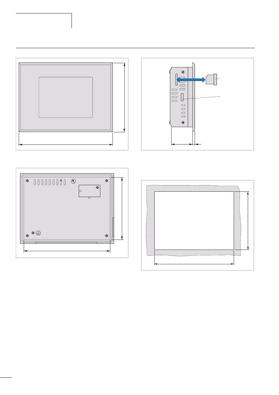
Appendix
10/10 MN04802002Z-EN
66
Dimensions
Figure 85: Front view
Figure 86: Rear view
212
156
139
195
Figure 87: Side view
a Memory card
b Cutout for fixing bracket
Figure 88: Mounting dimensions
54
5
a
b
198
142
- 0
+1
- 0 +1

10/10 MN04802002Z-EN
Technical data
67
Technical data
MFD4
General
Standards and regulations
IEC/EN 61131-2
EN 50178
Ambient temperature
with vertical mounting
°C
0 to 50
with diagonal mounting up to max. 45 °
°C
0 to 40
Storage temperature
°C
-20 to +70
Mounting position
vertical or diagonal mounting up to max. 45 °
Installation cut-out
mm
198 (-0+1) x 142 (-0+1)
Relative humidity, no condensation (IEC/EN 60068-2-30)
%
10 to 95
Air pressure (in operation)
hPa
795 to 1080
Vibration resistance
10 to 57 Hz g 0.075 mm
57 to 150 Hz g 1.0 g
Mechanical shock resistance
15 g/11 ms
Overvoltage category
II
Pollution degree
2
Degree of protection
Front
IP65
Rear
IP20
Rated insulation voltage
V
500
Emitted interference
EN 61000-6-4 Class A
Noise immunity
EN 61000-6-2
Battery (lifetime)
Lithium,1/2AA(3.6V) , normally 5 years
Weight
kg
1.3
Dimensions (W x H x D)
mm
212 x 156x 60
Terminals
Plug-in terminal block
Terminal capacity
Screw terminals
Flexible with ferrule
mm
2
0.5 to 1.5
solid
mm
2
0.5 to 2.5
Power supply
Input rated voltage
V DC
24
admissible range
V DC
20.4 to 28.8
Mains failure bridging
Duration of dip to IEC/EN 61131-2
ms
10
Current consumption
A
normally 0.4
Residual ripple
%
F 5
Overvoltage protection
Yes
Protection against polarity reversal
Yes
Inrush current
x In
No limitation (limited only by upstream 24 V DC power supply
unit)
Display

Appendix
10/10 MN04802002Z-EN
68
Diagonal
Inches
5.7
Type
TFT
Resolution
Pixels
320 x 240
Display area
mm
118 x 89
Colours
32000
Contrast ratio (Normally)
350 :1
Brightness (Normally)
cd/m2
500
Back-lighting
1 x CCFL
Lifespan
Operatin
g hours
Normally 50000 h at 25°C ambient temperature
(reduction of brightness to 50 %)
UV resistance
No
Operating unit
Type
Touchscreen
Technology
analog resistive
CPU
Microprocessor
RISC processor
Memory
Program code
KByte
4096
Program data
KByte
512
Markers
KByte
16
Retain data
KByte
32
Persistent Data
KByte
32
Watchdog
Yes
RTC (Real-Time Clock)
Yes
Accuracy of the real-time clock
1:20 hours per year
Memory card
Yes, optional, order separately
Interfaces
Ethernet interface
Baud rate
MBit/s
10/100
Connection types
RJ45
Electrical isolation
Yes
RS232 serial interface (without handshake line)
Baud rate
Bit/s
4800, 9600, 19200, 38400, 57600, 115200
Connection types
9-pole SUB-D plug (pins)
Electrical isolation
No
in Transparent mode
Baud rate
Bit/s
300, 600, 1200, 2400, 4800, 9600, 19200, 38400, 57600,
115200
Character formats
8E1, 8O1, 8N1, 8N2
MFD4

10/10 MN04802002Z-EN
Technical data
69
CANopen/easyNet
Electrical isolation
Yes
Bus terminating resistor
External
Connection types
9-pole SUB-D plug (pins)
CANopen operating mode
Device profile
To DS 301 V4
PDO type
Asyn., cyc., acyc.
Stations
Quantity
maximum 126
Baud rate
KBit/s
10/20/50/100/125/250/500/800/1000
Control mode easyNet
Stations
Quantity
max. 8
Baud rate
KBit/s
50/125
Electromagnetic compatibility
Noise immunity
ESD (IEC/EN 61000-4-2)
Contact discharge
4 kV
Air discharge
8 kV
RFI (IEC/EN 61000-4-3)
AM (80 %)
80 - 2000 MHz
10 V/m
GSM mobile
(IEC/EN
61000-4-3)
AM (80 %)
800 - 960 MHz
10 V/m
Burst (IEC/EN 61000-4-4)
Network
2 kV
Fieldbus
(capacitive coupling)
1 kV
Surge (IEC/EN 61000-4-5)
Mains DC, unsymmetrical
1 kV
Mains DC,
symmetrical
0.5 kV
Cable conducted interference, induced by high frequency fields
(previously: immunity to line-conducted interference) (IEC/EN 61000-4-6)
3 V
MFD4
Approvals and declarations
EMC
89/336/EEC
Explosions protection
ATEX Directive 94/9/EC
Device group II, Zone 22, category 3D, T85 °C
Shipping classifications
LR, GL, DNV, BV, ABS

10/10 MN04802002Z-EN
70
CANopen/easyNet
potential isolation
yes
Bus termination resistor
External
Connection
9-pole SUB-D plug (pins)
CANopen operating mode
Device profile
to DS301V4
PDO type
asyn., cyc., acyc.
Stations
max. 126
Baud rate
10/20/50/100/125/250/500/800/1000
Control mode easyNet
Stations
max. 8
Baud rate
50/125

10/10 MN04802002Z-EN
71
Index
Address overlaps . . . . . . . . . . . . . . . . . . . . . . . . . . . . . 35
Addressing
Inputs/outputs and markers . . . . . . . . . . . . . . . . . 35
Addressing markers . . . . . . . . . . . . . . . . . . . . . . . . . . . 35
Alarm functions, libraries . . . . . . . . . . . . . . . . . . . . . . . 30
Application screen . . . . . . . . . . . . . . . . . . . . . . . . . . . . 20
Backup time, battery . . . . . . . . . . . . . . . . . . . . . . . . . . . 7
Basic menu . . . . . . . . . . . . . . . . . . . . . . . . . . . . . . 17, 20
Battery . . . . . . . . . . . . . . . . . . . . . . . . . . . . . . . . . . . . . . 7
Baud rate, specifying/changing . . . . . . . . . . . . . . . . . . 37
Baudrate
Example for setting with routing . . . . . . . . . . . . . . 44
Boot project
Deleting a on a memory card . . . . . . . . . . . . . . . . 26
Deleting from memory card . . . . . . . . . . . . . . . . . 28
Breakpoint . . . . . . . . . . . . . . . . . . . . . . . . . . . . . . . . . . 25
Browser command “setlanguage” . . . . . . . . . . . . . . . . 61
Browser commands . . . . . . . . . . . . . . . . . . . . . . . . . . . 57
Bus terminating resistors . . . . . . . . . . . . . . . . . . . . . . . 15
Cable routing (Engineering informations) . . . . . . . . . . . 13
Calibrating, Display . . . . . . . . . . . . . . . . . . . . . . . . . . . 17
CAN
Telegrams, receive/send from user program . . . . . . 9
CAN baud rate . . . . . . . . . . . . . . . . . . . . . . . . . . . . . . . 45
CAN device parameters . . . . . . . . . . . . . . . . . . . . . . . . 45
CAN_Utilities. . . . . . . . . . . . . . . . . . . . . . . . . . . . . . . . 50
CanDevice . . . . . . . . . . . . . . . . . . . . . . . . . . . . . . . . . . 45
canload . . . . . . . . . . . . . . . . . . . . . . . . . . . . . . . . . . . . 60
CanMaster . . . . . . . . . . . . . . . . . . . . . . . . . . . . . . . . . . 45
CANopen
Bus interruption . . . . . . . . . . . . . . . . . . . . . . . . . . . 9
Display bus utilisation . . . . . . . . . . . . . . . . . . . . . . 60
Interface, Function . . . . . . . . . . . . . . . . . . . . . . . . . 9
Interface, Layout . . . . . . . . . . . . . . . . . . . . . . . . . . 15
Routing . . . . . . . . . . . . . . . . . . . . . . . . . . . . . . . . 46
Routing settings for master and device . . . . . . . . . 45
Updae variables with multitasking . . . . . . . . . . . . 32
CANopen cable, properties . . . . . . . . . . . . . . . . . . . . . 63
Changing screen, between application screen and basic
menu . . . . . . . . . . . . . . . . . . . . . . . . . . . . . . . . . . . . . . 20
Character formats . . . . . . . . . . . . . . . . . . . . . . . . . . . . 47
Clock . . . . . . . . . . . . . . . . . . . . . . . . . . . . . . . . . . . . . . 18
CoDeSys gateway server . . . . . . . . . . . . . . . . . . . . . . . 44
COLDSTART (Start behaviour) . . . . . . . . . . . . . . . . . . . 24
Command overview, Browser commands . . . . . . . . . . . 57
Commissioning . . . . . . . . . . . . . . . . . . . . . . . . . . . . . . 25
Communication
Channel . . . . . . . . . . . . . . . . . . . . . . . . . . . . . 37, 46
Channel (MFD4) setting . . . . . . . . . . . . . . . . . . . . 38
Error . . . . . . . . . . . . . . . . . . . . . . . . . . . . . . . . . . . 38
Communication parameter setting
For MFD4 via browser command . . . . . . . . . . . . . . 38
For PC in programming software . . . . . . . . . . . . . . 37
STARTUP.INI . . . . . . . . . . . . . . . . . . . . . . . . . . . . . 42
Communication, CANopen . . . . . . . . . . . . . . . . . . . . . . . 9
Configuration
MFD4, Visualisation task . . . . . . . . . . . . . . . . . . . . 29
CONFIGURE . . . . . . . . . . . . . . . . . . . . . . . . . . . . . . . . . 20
Connecting the power supply . . . . . . . . . . . . . . . . . . . . 14
Connection cable . . . . . . . . . . . . . . . . . . . . . . . . . . . . . 14
Contrast/Light . . . . . . . . . . . . . . . . . . . . . . . . . . . . . . . 18
Control panel layout . . . . . . . . . . . . . . . . . . . . . . . . . . 13
CPU
System loading . . . . . . . . . . . . . . . . . . . . . . . . . . . 60
Creating a boot project . . . . . . . . . . . . . . . . . . . . . . . . 26
Cross-over cable . . . . . . . . . . . . . . . . . . . . . . . . . . . . . . 14
Custom . . . . . . . . . . . . . . . . . . . . . . . . . . . . . . . . . . . . 19
D
Data transfer, easy IEC PLCs . . . . . . . . . . . . . . . . . . . . . 5
Data-saving . . . . . . . . . . . . . . . . . . . . . . . . . . . . . . . . . . 7
Debugging . . . . . . . . . . . . . . . . . . . . . . . . . . . . . . . 25, 57
Deleting
boot project on a memory card . . . . . . . . . . . . . . . 26
Operating system on memory card . . . . . . . . . . . . 28
Deleting the Startup.INI file . . . . . . . . . . . . . . . . . . . . . 42
Diagnostics
Via Browser commands . . . . . . . . . . . . . . . . . . . . . 57
via CAN (Routing) . . . . . . . . . . . . . . . . . . . . . . . . . 46
Dialog language, for errors and event lists . . . . . . . . . . 61
Dimensions . . . . . . . . . . . . . . . . . . . . . . . . . . . . . . . . . 66
disk_mmc . . . . . . . . . . . . . . . . . . . . . . . . . . . . . . . . . . . 8
Documentation, MFD4 . . . . . . . . . . . . . . . . . . . . . . . . . . 5
Download of programs . . . . . . . . . . . . . . . . . . . . . . . . 26
Drives . . . . . . . . . . . . . . . . . . . . . . . . . . . . . . . . . . . . . 65
Drives, CPU . . . . . . . . . . . . . . . . . . . . . . . . . . . . . . . . . . 8
Earthing, MFD4 . . . . . . . . . . . . . . . . . . . . . . . . . . . . . . 14
easyNet . . . . . . . . . . . . . . . . . . . . . . . . . . . . . . . . . . . . . 5
Interface, Function . . . . . . . . . . . . . . . . . . . . . . . . . 9
Interface, Layout . . . . . . . . . . . . . . . . . . . . . . . . . . 15
Electromagnetic contamination . . . . . . . . . . . . . . . . . . 13
Engineering . . . . . . . . . . . . . . . . . . . . . . . . . . . . . . . . . 13
Enter the IP address . . . . . . . . . . . . . . . . . . . . . . . . . . . 38
Erase error list . . . . . . . . . . . . . . . . . . . . . . . . . . . . . . . 58
Erase event list . . . . . . . . . . . . . . . . . . . . . . . . . . . . . . . 58
Erase file . . . . . . . . . . . . . . . . . . . . . . . . . . . . . . . . . . . 58
Erase password for online access . . . . . . . . . . . . . . . . . 58
Error list . . . . . . . . . . . . . . . . . . . . . . . . . . . . . . . . . . . . 61
Ethernet cable, properties . . . . . . . . . . . . . . . . . . . . . . 63
Ethernet interface . . . . . . . . . . . . . . . . . . . . . . . . . . 9, 14
Parameter definition . . . . . . . . . . . . . . . . . . . . . . . 18
Ethernet utilities . . . . . . . . . . . . . . . . . . . . . . . . . . . . . . 51
Event controlled task . . . . . . . . . . . . . . . . . . . . . . . . . . 31

Index
10/10 MN04802002Z-EN
72
Factory set . . . . . . . . . . . . . . . . . . . . . . . . . . . . . . . . . .26
Flash . . . . . . . . . . . . . . . . . . . . . . . . . . . . . . . . . . . . . . . .8
Flush mounting, MFD4 . . . . . . . . . . . . . . . . . . . . . . . . .11
Forcing, variable . . . . . . . . . . . . . . . . . . . . . . . . . . . . . .25
Functions
CAN_BUSLOAD . . . . . . . . . . . . . . . . . . . . . . . . . . .50
SysFile… . . . . . . . . . . . . . . . . . . . . . . . . . . . . . . . .65
UTI2_GetIPDNS . . . . . . . . . . . . . . . . . . . . . . . . . . .51
UTI2_GetIPWINS . . . . . . . . . . . . . . . . . . . . . . . . . .52
UTI2_GetMacAddress . . . . . . . . . . . . . . . . . . . . . .52
UTI2_SetIPDNS . . . . . . . . . . . . . . . . . . . . . . . . . . .53
UTI2_SetIPGateway . . . . . . . . . . . . . . . . . . . . . . . .54
UTI2_SetIPWINS . . . . . . . . . . . . . . . . . . . . . . . . . .54
getipconfig, browser command . . . . . . . . . . . . . . . . . . .39
getlanguage, Browser command . . . . . . . . . . . . . . . . . .61
gettargetname, browser command . . . . . . . . . . . . . . . .42
HALT (start behaviour) . . . . . . . . . . . . . . . . . . . . . . . . .24
Help, for browser comands . . . . . . . . . . . . . . . . . . . . . .59
Inductors . . . . . . . . . . . . . . . . . . . . . . . . . . . . . . . . . . .13
Inputs
Addressing . . . . . . . . . . . . . . . . . . . . . . . . . . . . . . .35
Referencing . . . . . . . . . . . . . . . . . . . . . . . . . . . . . .25
Interface . . . . . . . . . . . . . . . . . . . . . . . . . . . . . . . . . . . .14
Function . . . . . . . . . . . . . . . . . . . . . . . . . . . . . . . . .9
Setting communication parameters . . . . . . . . . . . .37
Interference factors . . . . . . . . . . . . . . . . . . . . . . . . . . . .13
Interrupt, CANopen Bus . . . . . . . . . . . . . . . . . . . . . . . . .9
Interval time . . . . . . . . . . . . . . . . . . . . . . . . . . . . . . . . .29
IP address
Changing (Dynamic Name Server) . . . . . . . . . . . . .53
Changing (Windows Name Server) . . . . . . . . . . . . .54
Display (Dynamic Name Server) . . . . . . . . . . . . . . .51
Display (Windows Name Server) . . . . . . . . . . . . . .52
Output . . . . . . . . . . . . . . . . . . . . . . . . . . . . . . . . . .51
Scan/modify . . . . . . . . . . . . . . . . . . . . . . . . . . . . . .39
IP-Address
Set . . . . . . . . . . . . . . . . . . . . . . . . . . . . . . . . . . . . .53
Display.lib . . . . . . . . . . . . . . . . . . . . . . . . . . . . . . .50
Installing . . . . . . . . . . . . . . . . . . . . . . . . . . . . . . . .49
MFD57_UTIL.lib . . . . . . . . . . . . . . . . . . . . . . . . . . .50
Library . . . . . . . . . . . . . . . . . . . . . . . . . . . . . . . . . . . . .65
Lightning protection . . . . . . . . . . . . . . . . . . . . . . . . . . .14
Limit values, for memory usage . . . . . . . . . . . . . . . . . . .35
Main memory . . . . . . . . . . . . . . . . . . . . . . . . . . . . . . . . 8
Manuals, MFD4 . . . . . . . . . . . . . . . . . . . . . . . . . . . . . . . 5
Memory
card . . . . . . . . . . . . . . . . . . . . . . . . . . . . . . . . . 8, 65
Systems . . . . . . . . . . . . . . . . . . . . . . . . . . . . . . . . . 8
User program . . . . . . . . . . . . . . . . . . . . . . . . . . . . . 7
Utilization, limits . . . . . . . . . . . . . . . . . . . . . . . . . 35
MFD4 . . . . . . . . . . . . . . . . . . . . . . . . . . . . . . . . . . . . . 11
MMC memory card . . . . . . . . . . . . . . . . . . . . . . . . . . . . 8
Monitoring time, task . . . . . . . . . . . . . . . . . . . . . . . . . 33
Mounting . . . . . . . . . . . . . . . . . . . . . . . . . . . . . . . . . . 11
Multimedia card . . . . . . . . . . . . . . . . . . . . . . . . . . . . . . 8
Multitasking . . . . . . . . . . . . . . . . . . . . . . . . . . . . . 29, 32
Network, easyNet . . . . . . . . . . . . . . . . . . . . . . . . . . . . . 5
Node guarding function . . . . . . . . . . . . . . . . . . . . . . . . 9
Node ID . . . . . . . . . . . . . . . . . . . . . . . . . . . . . . . . . . . 44
Node number . . . . . . . . . . . . . . . . . . . . . . . . . . . . . . . 44
O
Operating system
deleting, from memory card . . . . . . . . . . . . . . . . . 28
Transferring, from the PC into the PLC . . . . . . . . . 27
Operating System Version . . . . . . . . . . . . . . . . . . . . . . 19
Operation, MFD4 . . . . . . . . . . . . . . . . . . . . . . . . . . . . 21
OS version . . . . . . . . . . . . . . . . . . . . . . . . . . . . . . . . . . 19
Output MAC address . . . . . . . . . . . . . . . . . . . . . . . . . . 52
Outputs
Addressing . . . . . . . . . . . . . . . . . . . . . . . . . . . . . . 35
Referencing . . . . . . . . . . . . . . . . . . . . . . . . . . . . . 25
P
Parameters
Setting via the display . . . . . . . . . . . . . . . . . . . . . 17
PC – MFD4 connection
Setting in easySoft . . . . . . . . . . . . . . . . . . . . . . . . 37
PING response . . . . . . . . . . . . . . . . . . . . . . . . . . . . . . 39
Plc . . . . . . . . . . . . . . . . . . . . . . . . . . . . . . . . . . . . . . . . 19
Point-to-point connection . . . . . . . . . . . . . . . . . . . . . . . 9
Power off/interruption of the power supply (behaviour) 24
Priority (task) . . . . . . . . . . . . . . . . . . . . . . . . . . . . . . . . 29
Program
Call (task) . . . . . . . . . . . . . . . . . . . . . . . . . . . . . . 31
Call definition, for task . . . . . . . . . . . . . . . . . . . . . 31
Loading . . . . . . . . . . . . . . . . . . . . . . . . . . . . . . . . 26
Processing . . . . . . . . . . . . . . . . . . . . . . . . . . . . . . 29
Programming interface . . . . . . . . . . . . . . . . . . . . . . . . . 9
Programming via the CANopen network (routing) . . . . 43
Protection against polarity reversal . . . . . . . . . . . . . . . 14

10/10 MN04802002Z-EN
Index
73
Real-time clock . . . . . . . . . . . . . . . . . . . . . . . . . . . . . . . 7
Reboot . . . . . . . . . . . . . . . . . . . . . . . . . . . . . . . . . . . . . 18
Registry save . . . . . . . . . . . . . . . . . . . . . . . . . . . . . 55, 57
removeprojfrommmc, Browser command . . . . . . . . . . . 42
removestartupini, browser command . . . . . . . . . . . . . . 42
Reset . . . . . . . . . . . . . . . . . . . . . . . . . . . . . . . . . . . 17, 25
Restart, registry save . . . . . . . . . . . . . . . . . . . . . . . . . . 55
Restoring factory settings . . . . . . . . . . . . . . . . . . . . . . 26
Retentive variables . . . . . . . . . . . . . . . . . . . . . . . . . . . 24
RJ45 interface . . . . . . . . . . . . . . . . . . . . . . . . . . . . . . . 14
Routing . . . . . . . . . . . . . . . . . . . . . . . . . . . . . . . . . . . . . 5
via CANopen . . . . . . . . . . . . . . . . . . . . . . . . . . . . 43
RS232-interface . . . . . . . . . . . . . . . . . . . . . . . . . . . . 9, 15
Run, MFD4 . . . . . . . . . . . . . . . . . . . . . . . . . . . . . . . . . 19
Screen saver . . . . . . . . . . . . . . . . . . . . . . . . . . . . . . . . 19
Screensaver . . . . . . . . . . . . . . . . . . . . . . . . . . . . . . . . . 19
Segments . . . . . . . . . . . . . . . . . . . . . . . . . . . . . . . . . . . 35
Set time . . . . . . . . . . . . . . . . . . . . . . . . . . . . . . . . . . . . 18
setipconfig, browser command . . . . . . . . . . . . . . . . . . 39
Setting
IPGateway address . . . . . . . . . . . . . . . . . . . . . . . . 54
Changing . . . . . . . . . . . . . . . . . . . . . . . . . . . . . . . 37
Shielding . . . . . . . . . . . . . . . . . . . . . . . . . . . . . . . . . . . 13
Single-cycle mode . . . . . . . . . . . . . . . . . . . . . . . . . . . . 25
Single-step mode . . . . . . . . . . . . . . . . . . . . . . . . . . . . . 25
Start behaviour . . . . . . . . . . . . . . . . . . . . . . . . . . . . . . 21
Starting
MFD4 via display . . . . . . . . . . . . . . . . . . . . . . . . . 19
Start-up behaviour
Configuring with XSoft . . . . . . . . . . . . . . . . . . . . . 24
STARTUP.INI file . . . . . . . . . . . . . . . . . . . . . . . . . . . . . 41
Status display
Inputs/outputs CAN station . . . . . . . . . . . . . . . . . 25
Several CAN stations simultaneously (Routing) . . . 46
Stop program . . . . . . . . . . . . . . . . . . . . . . . . . . . . . . . . 24
Subnetmask address . . . . . . . . . . . . . . . . . . . . . . . . . . 51
Set . . . . . . . . . . . . . . . . . . . . . . . . . . . . . . . . . . . . 53
Suppressor circuitry for interference sources . . . . . . . . . 13
Switch . . . . . . . . . . . . . . . . . . . . . . . . . . . . . . . . . . . . . 15
System
Events . . . . . . . . . . . . . . . . . . . . . . . . . . . . . . 29, 32
load, CPU . . . . . . . . . . . . . . . . . . . . . . . . . . . . . . . 60
Memory . . . . . . . . . . . . . . . . . . . . . . . . . . . . . . . . . 8
parameter predefined (via STARTUP.INI file) . . . . . 41
T
Task
Condition . . . . . . . . . . . . . . . . . . . . . . . . . . . . . . . 29
Configuration . . . . . . . . . . . . . . . . . . . . . . . . . . . . 29
Creating/configuring . . . . . . . . . . . . . . . . . . . . . . . 31
Monitoring . . . . . . . . . . . . . . . . . . . . . . . . . . . . . . 33
POU creation, setting the program call . . . . . . . . . 31
TCP/IP
Connection . . . . . . . . . . . . . . . . . . . . . . . . . . . . . . 43
Setting . . . . . . . . . . . . . . . . . . . . . . . . . . . . . . . . . 18
Technical data . . . . . . . . . . . . . . . . . . . . . . . . . . . . . . . 67
Test and commissioning . . . . . . . . . . . . . . . . . . . . . . . . 25
Text output, via the RS-232 interface . . . . . . . . . . . . . . 64
Transparent mode . . . . . . . . . . . . . . . . . . . . . . . . . . 9, 47
Example text output via RS232 . . . . . . . . . . . . . . . 64
Trend functions, libraries . . . . . . . . . . . . . . . . . . . . . . . 30
Type (task condition) . . . . . . . . . . . . . . . . . . . . . . . . . . 29
User program, memory values . . . . . . . . . . . . . . . . . . . . 7
User task . . . . . . . . . . . . . . . . . . . . . . . . . . . . . . . . . . . 29
Ventilation . . . . . . . . . . . . . . . . . . . . . . . . . . . . . . . . . . 13
Visualization . . . . . . . . . . . . . . . . . . . . . . . . . . . . . . . . 29
Watchdog . . . . . . . . . . . . . . . . . . . . . . . . . . . . . . . . . . 33
Web visualization . . . . . . . . . . . . . . . . . . . . . . . . . . . . . 34
Wiring (Engineering informations) . . . . . . . . . . . . . . . . 13
Document Outline
- Title
- Imprint
- Safety Instructions
- Contents
- About this manual
- 1 Setup of the MFD4
- 2 Mounting the MFD4
- 3 Engineering
- 4 MFD4 operation
- 5 Operation
- 6 Program processing, multitasking and system times
- 7 Establishing a PC – MFD4 connection
- 8 Defining the system parameters via the STARTUP.INI file
- 9 Programming via the CANopen network (routing)
- 10 RS232 interface in Transparent mode
- 11 Libraries, function blocks and functions
- Using libraries
- Installing additional system libraries
- MFD specific functions
- CAN utilities
- Ethernet utilities
- UTI2_GetIPConfig Get IP, subnet mask and IPGateway address
- UTI2_GetIPDNS Display IP address of the dynamic name server set on the MFD4
- UTI2_GetIPWINS Display IP address of the Windows name server set on the MFD4
- UTI2_GetMacAddress Get MAC address (MAC=Media Access Control)
- UTI2_SetIPConfig Setting the IP- and subnet mask address
- UTI2_SetIPDNS Change the IP address of the dynamic name server on the MFD4
- UTI2_SetIPGateway Setting of the IP Gateway address
- UTI2_SetIPWINS Change the IP address of the Windows name server on the MFD4
- General functions
- 12 Browser commands
- Appendix
- Index
Wyszukiwarka
Podobne podstrony:
Multi functional cremation container for
Audi A4 Multi function steering wheel 2001
Multi functional cremation container for
L 3 Complex functions and Polynomials
multi demultiplekser
3 ABAP 4 6 Basic Functions
KB04 SMD DISPLAY
LG MULTI V
Functional Origins of Religious Concepts Ontological and Strategic Selection in Evolved Minds
MEDC17 Special Function Manual
Verb form and function
dpf doctor diagnostic tool for diesel cars function list
Euler’s function and Euler’s Theorem
Attitudes toward Affirmative Action as a Function of Racial ,,,
nutritional modulation of immune function
ALAN42 MULTI component side
Multi PIN AEGON Firma 2008
Karta katalogowa Klimatyzator typu Multi Split V
więcej podobnych podstron