
ALTERNATOR & REGULATOR
1993 Mitsubishi Montero
1993 ELECTRICAL
Mitsubishi Alternators & Regulators
Montero
DESCRIPTION
Mitsubishi alternators are conventional 3-phase, self-
rectifying type units containing 6 diodes (3 positive and 3 negative)
which are used to rectify current. All models use a case-mounted
Integrated Circuit (IC) voltage regulator.
Alternator relay or resistor with diode is used to ensure
charging of battery even if charging indicator light is defective.
ADJUSTMENTS
ALTERNATOR BELT ADJUSTMENT TABLE
Deflection
Application In. (mm)
New Belt (1) ........................... .25-.31 (6.4-7.9)
Used Belt (1) .................................. .35 (8.9)
(1) - With 22 lbs. (10 kg) pressure applied midway on belt
run.
TROUBLE SHOOTING
NOTE: See TROUBLE SHOOTING - BASIC PROCEDURES article in
the GENERAL INFORMATION Section.
ON-VEHICLE TESTING
ALTERNATOR TO BATTERY CONTINUITY TEST
NOTE: Check alternator wiring harness connections and drive belt
tension and ensure battery is fully charged before
performing test.
1) Turn ignition switch to OFF position. Disconnect negative
battery cable. Remove output lead from alternator terminal "B". See
Fig. 1. Install a 100-amp ammeter in series with terminal "B" and
disconnected output lead. Install positive lead of ammeter to terminal
"B" and negative lead to disconnected output wire.
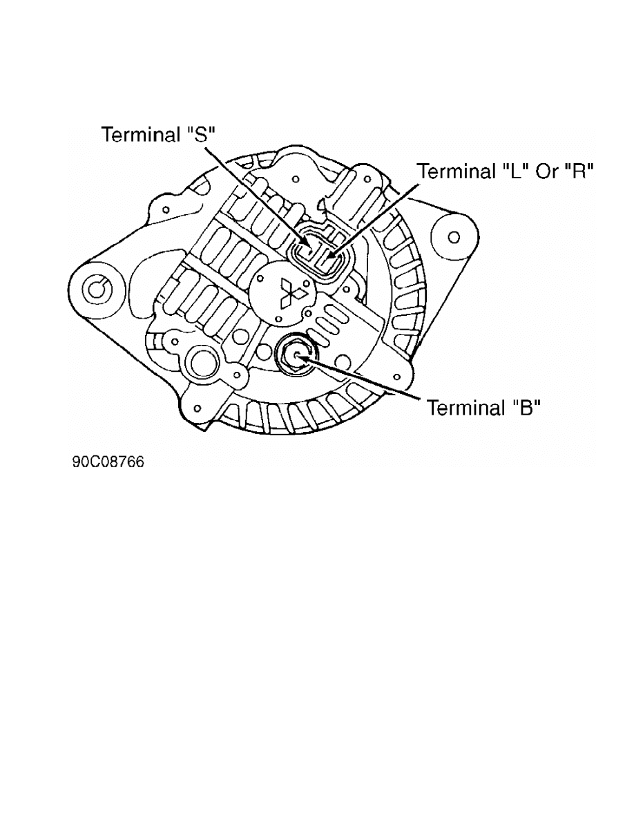
Fig. 1: Alternator Terminal ID
Courtesy of Mitsubishi Motor Sales of America.
2) Install a digital voltmeter between alternator terminal
"B" and positive battery terminal. Install positive voltmeter lead to
terminal "B" and negative lead to positive battery terminal. Reconnect
negative battery cable.
3) Start engine. Turn accessories on and adjust engine speed
until ammeter indicates 20 amps, and note voltmeter reading. If
voltmeter indicates .2 volt or less, system is okay.
4) If voltage is greater than .2 volt, wiring is defective
between alternator terminal "B", fusible link and positive battery
terminal. Disconnect negative battery cable, and remove test
equipment.
ALTERNATOR OUTPUT TEST
NOTE: During alternator output test, a slightly discharged battery
should be used as a fully charged battery may not allow full
alternator output.
1) Turn ignition switch to OFF position. Disconnect negative
battery cable. Disconnect alternator output wire from terminal "B".
Install positive lead of 100-amp ammeter to terminal "B" and negative
lead to disconnected output lead.
CAUTION: Tighten each connection securely as heavy current flow will
exist. DO NOT use clips on ammeter.
2) Connect positive voltmeter lead (0-20 volts) to alternator

terminal "B" and negative lead to ground. Install tachometer, and
reconnect negative battery cable.
3) Ensure voltmeter indicates battery voltage. If no voltage
exists, an open circuit is present in wire between alternator terminal
"B" and negative battery terminal. Check grounds and fusible link.
4) Turn headlights on, and start engine. Set headlights at
high beam and heater switch on HIGH. Quickly accelerate engine speed
to 2500 RPM and note alternator output current on ammeter. Minimum
output should be within specification. See ALTERNATOR MINIMUM OUTPUT
SPECIFICATIONS table.
NOTE: Output voltage changes with electrical load and temperature.
Ensure proper electrical load is applied while checking
output. Nominal output may not be obtained if alternator or
ambient temperature is excessive. Allow alternator or
temperature to cool, and recheck output. Alternator output
is stamped on metal plate attached to alternator case.
5) If minimum output is not obtained and alternator wiring is
okay, repair alternator. Disconnect negative battery cable, and remove
test equipment.
ALTERNATOR MINIMUM OUTPUT SPECIFICATIONS TABLE
Application Amps
Montero ............................................. 52.5
REGULATED VOLTAGE TEST
NOTE: Ensure battery is fully charged and proper drive belt
tension exists.
1) Turn ignition switch to OFF position. Disconnect negative
battery cable. Connect positive voltmeter lead to terminal "S" of
alternator. See Fig. 1. Connect negative voltmeter lead to ground.
2) Disconnect alternator output wire from terminal "B".
Install a 100-amp ammeter in series with terminal "B" and disconnected
output lead. Install positive lead of ammeter to terminal "B" and
negative lead to disconnected output wire. Install a tachometer, and
reconnect negative battery cable.
3) Turn ignition switch to ON position and ensure voltmeter
indicates battery voltage. If no voltage exists, there is an open in
wire between alternator terminal "S" and positive battery terminal or
fusible link is blown.
4) Start engine. Ensure all lights and accessories are off.
Operate engine at 2500 RPM and read voltmeter when alternator output
current drops to 10 amps or less. Voltage regulator is okay if voltage
output is within specification. See REGULATOR VOLTAGE SPECIFICATIONS
table.
REGULATOR VOLTAGE SPECIFICATIONS TABLE
Ambient Temperature Voltage
-4
F (-20
C) ................................... 14.2-15.4
68
F (20
C) .................................... 13.9-14.9
140
F (60
C) ................................... 13.4-14.6
176
F (80
C) ................................... 13.1-14.5
BENCH TESTING
RECTIFIER ASSEMBLY
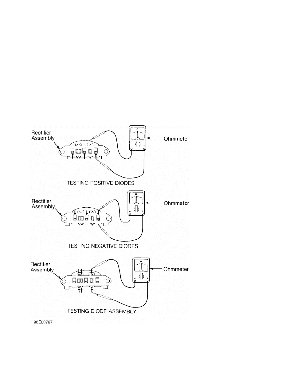
1) Using ohmmeter, check for continuity between diodes and
stator coil lead connection. See Fig. 2. Reverse leads. If continuity
exists in both directions, diode is shorted. Replace rectifier
assembly.
2) To check entire diode assembly, use an ohmmeter to check
for continuity between both ends of each diode. See Fig. 2. Switch
ohmmeter leads. Continuity should exist in one direction only. If no
continuity exists or continuity exists in both directions, diode is
defective. Replace rectifier assembly.
Fig. 2: Testing Rectifier Assembly
Courtesy of Mitsubishi Motor Sales of America.
ROTOR
1) Check continuity across rotor slip rings. Resistance
should be 3-5 ohms. Replace rotor if no continuity exists or
resistance is not within specification.
2) Check continuity between individual slip rings and rotor
shaft. If continuity exists, rotor coil or slip ring is grounded.
Replace rotor.
STATOR
Ensure no continuity exists between stator coil leads and
stator core. Check continuity between leads of stator coil. If no
continuity exists between coil leads, replace stator.
OVERHAUL
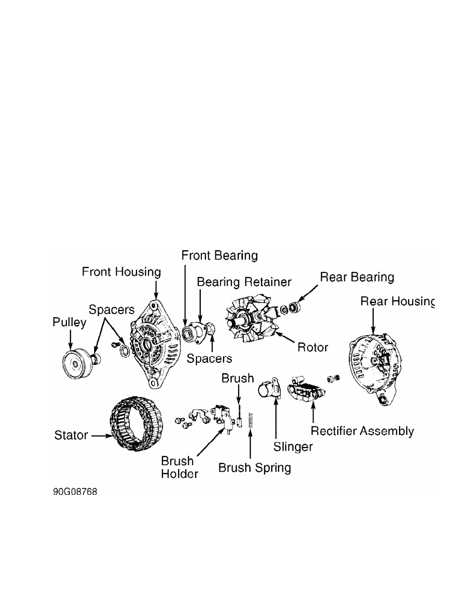
Replace brushes if worn to limit line. Limit line is line
closest to rotor contact end of brush. Brushes can be retained in
brush holder while installing rotor by inserting wire into back of
rear housing. See Fig. 3.
Fig. 3: Exploded View Of Typical Mitsubishi Alternator
Courtesy of Mitsubishi Motor Sales of America.
WIRING DIAGRAMS
See appropriate WIRING DIAGRAM in the WIRING DIAGRAMS
Section.

Wyszukiwarka
Podobne podstrony:
Basel II and Regulatory Framework for Islamic Banks
Alternatory, rozruszniki, regulatory
Basel II and Regulatory Framework for Islamic Banks
Immunologic tolerance and regulation
an alternative and simple preparation of tryptamine from l tryptophan by catalytic decarboxylation w
inside out int rules and regulations
1999 USA Ju Jitsu Official Rules and Regulations
Sulphur handle setup and regulation sheet 6
REGUŁA DOŁĄCZANIA ALTERNATYWY
Alternator Check and Replacement
Advantages and disadvantages of alternative medicine
REGUŁA DOŁĄCZANIA ALTERNATYWY
Turtledove, Harry Alternate Generals II Advance and Retreat
Ebsco Garnefski Negative life events, cognitive emotion regulation and emotional problems
Military Regulations on the Acceptance of Alternate Religious Practices
Ebsco Garnefski Cognitive emotion regulation strategies and emotional problems in 9 11 year old ch
PORADNIK badanie alternatora i regulatora
więcej podobnych podstron