
Steel Design Guide Series
Low-and Medium-Rise
Steel Buildings

Low- and
Medium-Rise
Steel Buildings
Design Guide for Low- and Medium-Rise Steel Buildings
Horatio Allison, PE
Consulting Engineer
Dagsboro, Delaware
A M E R I C A N
I N S T I T U T E O F S T E E L
C O N S T R U C T I O N
Steel Design Guide Series
© 2003 by American Institute of Steel Construction, Inc. All rights reserved.
This publication or any part thereof must not be reproduced in any form without permission of the publisher.

Copyright
1991
by
American Institute of Steel Construction, Inc.
All rights reserved. This book or any part thereof
must not be reproduced in any form without the
written permission of the publisher.
The information presented in this publication has been prepared in accordance with rec-
ognized engineering principles and is for general information only. While it is believed
to be accurate, this information should not be used or relied upon for any specific appli-
cation without competent professional examination and verification of its accuracy,
suitablility, and applicability by a licensed professional engineer, designer, or architect.
The publication of the material contained herein is not intended as a representation
or warranty on the part of the American Institute of Steel Construction or of any other
person named herein, that this information is suitable for any general or particular use
or of freedom from infringement of any patent or patents. Anyone making use of this
information assumes all liability arising from such use.
Caution must be exercised when relying upon other specifications and codes developed
by other bodies and incorporated by reference herein since such material may be mod-
ified or amended from time to time subsequent to the printing of this edition. The
Institute bears no responsibility for such material other than to refer to it and incorporate
it by reference at the time of the initial publication of this edition.
Printed in the United States of America
Second Printing: October 2003
© 2003 by American Institute of Steel Construction, Inc. All rights reserved.
This publication or any part thereof must not be reproduced in any form without permission of the publisher.

TABLE OF CONTENTS
BASIC DESIGN RULES FOR ECONOMY . . . . . . .
LIVE LOAD AND BAY SIZE SELECTION . . . . . .
Live Load Selection . . . . . . . . . . . . . . . . . . . . . . . . . .
Bay Size S e l e c t i o n . . . . . . . . . . . . . . . . . . . . . . . . . . . .
COMPOSITE FLOORS . . . . . . . . . . . . . . . . . . . . . . . .
Allowable Stress (ASD) and Load
Resistance Factor Design (LRFD) . . . . . . . . . . . . .
Economy with LRFD . . . . . . . . . . . . . . . . . . . . . . . . .
Floor Load Capacity E n h a n c e m e n t . . . . . . . . . . . . . .
Shored vs. Unshored C o n s t r u c t i o n . . . . . . . . . . . . . . .
Serviceability Considerations . . . . . . . . . . . . . . . . . . .
Underfloor Duct Systems . . . . . . . . . . . . . . . . . . . . . .
OPEN WEB JOIST FLOOR SYSTEMS . . . . . . . . . .
Joist Size and Spacing . . . . . . . . . . . . . . . . . . . . . . . .
Girder Beam Design . . . . . . . . . . . . . . . . . . . . . . . . . .
Composite Joist S y s t e m s . . . . . . . . . . . . . . . . . . . . . . .
Floor Vibration . . . . . . . . . . . . . . . . . . . . . . . . . . . . . .
WIND LOAD D E S I G N . . . . . . . . . . . . . . . . . . . . . . . . .
Drift Limits . . . . . . . . . . . . . . . . . . . . . . . . . . . . . . . . .
"K" Bracing Frame . . . . . . . . . . . . . . . . . . . . . . . . . .
Unbraced Frame Design . . . . . . . . . . . . . . . . . . . . . . .
Special Wind Frames . . . . . . . . . . . . . . . . . . . . . . . . .
APPENDICES . . . . . . . . . . . . . . . . . . . . . . . . . . . . . . . .
LRFD Composite Beam D e s i g n . . . . . . . . . . . . . . . . .
Composite Beam Load Capacity Enhancement . . . .
Composite Beam Long Term Deflection . . . . . . . . . .
Steel Joist Typical Bay . . . . . . . . . . . . . . . . . . . . . . . .
K-Frame Bracing Optimization . . . . . . . . . . . . . . . . .
Unbraced Frame Design . . . . . . . . . . . . . . . . . . . . . . .
iii
1
1
2
2
5
5
6
6
7
8
8
10
10
10
10
11
12
12
13
15
17
23
23
25
29
31
33
36
© 2003 by American Institute of Steel Construction, Inc. All rights reserved.
This publication or any part thereof must not be reproduced in any form without permission of the publisher.

PREFACE
This booklet was prepared under the direction of the Com-
mittee on Research of the American Institute of Steel Con-
struction, Inc. as part of a series of publications on special
topics related to fabricated structural steel. Its purpose is to
serve as a supplemental reference to the AISC Manual of
Steel Construction to assist practicing engineers engaged in
building design.
The design guidelines suggested by the author that are out-
side the scope of the AISC Specifications or Code do not
represent an official position of the Institute and are not in-
tended to exclude other design methods and procedures. It
is recognized that the design of structures is within the scope
of expertise of a competent licensed structural engineer,
architect, or other licensed professional for the application
of principles to a particular structure.
The sponsorship of this publication by the American Iron
and Steel Institute is gratefully acknowledged.
iv
The information presented in this publication has been prepared in accordance with recognized engineer-
ing principles and is for general information only. While it is believed to be accurate, this information should
not be used or relied upon for any specific application without competent professional examination and verifi-
cation of its accuracy, suitability, and applicability by a licensed professional engineer, designer, or archi-
tect. The publication of the material contained herein is not intended as a representation or warranty on
the part of the American Institute of Steel Construction, Inc. or the American Iron and Steel Institute, or
of any other person named herein, that this information is suitable for any general or particular use or of
freedom from infringement of any patent or patents. Anyone making use of this information assumes all lia-
bility arising from such use.
© 2003 by American Institute of Steel Construction, Inc. All rights reserved.
This publication or any part thereof must not be reproduced in any form without permission of the publisher.

DESIGN OF LOW- AND MEDIUM-RISE STEEL BUILDINGS
BASIC DESIGN RULES FOR ECONOMY
A few basic design rules for economy will be presented
herein. These rules should be considered in the conceptual
phase in the design of a project. There are, of course, many
other considerations, but these suggestions are simple and
can help in producing a good economical design.
The cost of a filler beam and/or girder beam simply con-
sists of the cost of the mill material, the cost of fabrication,
and the cost of erection. The cost of fabrication and erec-
tion for a single beam is essentially the same for a heavy
beam or a light beam. The real savings for a light member
compared to a heavier one is simply the difference in the
cost of the mill material. Thus, beams should be spaced as
far apart as practical to reduce the number of pieces which
must be fabricated and erected.
Rigid moment connections and special connections for
bracing are expensive. Care should be taken to minimize the
number of these types of connections in a project—that is,
reduce the number of moment resisting and braced bents to
the minimum. Where practical, one may consider the use of
only spandrel moment resisting frames to resist wind loads.
Deeper, more efficient sections may be used thus minimiz-
ing the number of moment resisting connections required.
Where appropriate, high strength steel =
50
ksi)
should be used in lieu of mild steel =
36
ksi)
for
both
columns and beams. The reason is simple—the price to
strength ratio is about 25% lower for the higher strength steel
beams and 10% to 15% lower for columns depending upon
their length. For example, a W21x44
= 36 ksi) simple
filler beam is the equivalent of a W16x26 =
50 ksi)
composite filler beam. The difference in the cost of the mill
material to the fabricator is about $3.90 per linear foot. The
cost of the studs in place at a cost of $1.50 each is about
$1.30 per linear foot. The cost of cambering or shoring is
considerably less than the $2.60 per foot difference. The floor
vibration ratings for the two beams are comparable. The
required critical damping using Murray's criterion (Murray,
1991) for the W21x44 and W16x26 spanning 30 '-0 " spaced
10 '-0" o.c. with 10 psf ambient live load is 4.00 and 3.46
respectively. The higher strength steel beam is less costly
and functionally equivalent. It should be kept in mind that
there are situations where the use of high strength steel is
inappropriate. Small inconsequential filler beams, channels,
angles, etc., should be of
= 36 ksi steel, as this mate-
rial is readily available from a fabricator's stock or a steel
supply warehouse. Members for which strength is not the
controlling design consideration, obviously =
36
ksi
material should be used.
Repetitive use of members and/or the same shape size is
an important factor in the design of an economical project.
Repetitive use of members reduces the detailing, fabrication,
and erection costs. As an example, in composite construc-
tion where beam spacing for non-typical areas is reduced,
consideration should be given to the use of the typical size
beam section with a reduction in the number of studs. The
simpler the framing, the lower the final estimated cost is
likely to be at bid time and, as a result, the lower the total
square foot cost of the project.
Use live load reductions for the design of members where
possible. While live load reduction may not result in any sub-
stantial reduction in filler beam weights, a change of one size,
perhaps a reduction from a W16x31 to a W16x26, will result
in a 16% savings in the filler beam mill material required.
The savings in girder and column weights and the cost of
foundations are likely to be significant.
The level of inspection specified should be consistent with
that required to insure that the completed structure will be
functional. Except in unusual circumstances, visual inspec-
tion should be adequate for fillet welds. The extent of non-
destructive testing of butt welds may be finally determined
during the construction period. If the results of tests are mar-
ginal, the number of tests can be increased. If the results
of the tests are consistently good, the number of tests may
be reduced. Especially for large projects, it may be prudent
to require AISC certified fabricators in order to insure good
quality control and a more trouble-free project.
Finally, paint only members required by the AISC Speci-
fication. Unpainted surfaces should be used when in con-
tact with concrete. Fireproofing material more readily
adheres to unpainted surfaces. While painting costs may only
be $.15 to $.20 per square foot, for a 200,000 square foot
project the cost saving of $30,000 to $40,000 is real and is
there for the taking.
LIVE LOAD AND BAY SIZE SELECTION
Most buildings are economic machines of one sort or another.
In particular, many office building structures are built on a
speculative basis. The success of the venture may be a func-
tion of the building's planning and serviceability potential.
Larger bay sizes increase the flexibility in space planning.
Higher design live loads also increase the flexibility in the
uses permitted in office space. Buildings with higher live
load capacities and larger bay sizes are obviously more attrac-
tive to potential building tenants and more valuable to build-
ing owners. It will be shown that larger bay sizes and higher
1
© 2003 by American Institute of Steel Construction, Inc. All rights reserved.
This publication or any part thereof must not be reproduced in any form without permission of the publisher.
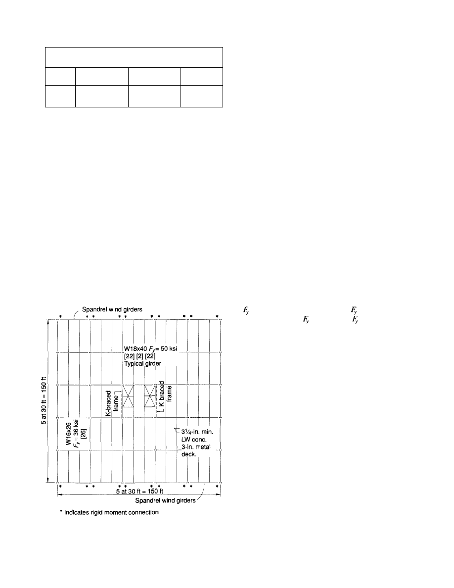
Table 1.
Typical Interior Column Load Comparison
Design
ASD
LRFD
50 PSFLL
+20 PSFPART
100%
100%
80 PSFLL
+ 20 PSFPART
110%
100 PSFLL
100%
105%
than promulgated minimum live loads can be achieved with
no significant increase in cost.
Live Load Selection
Sometimes developers and/or designers select the minimum
live load permitted by the building code. This is a seemingly
obvious choice if the costs are to be kept to an absolute mini-
mum. It is possible to upgrade from the minimum permit-
ted design live load of 50 psf plus 20 psf partition load to
a 100 psf live load capacity (with no additional partition load
allowance) at virtually no increase in cost.
As an example, we will compare the differences for a typi-
cal office building with 30 ft square bays and 10 stories in
height (Fig. 1). Comparisons will be made for 50 psf live
load plus 20 psf partition load, 80 psf live load plus 20 psf
partition load, and 100 psf live with no partition load load-
ings. Column load comparisons are shown for a typical
interior column for the AISC Allowable Stress Design (ASD)
Specification (AISC, 1978) and the AISC Load and Resis-
tance Factor Design (LRFD) Specification (AISC, 1986).
Fig. 1. Typical office building floor plan.
Live load reductions are made in accordance with ASCE 7-88
(formerly ANSI A58.1). Table 1 is a percentage comparison
of the tabulated column loads at the base of the ten story
building for the three design load combinations. For ASD
design, the column load is identical for that of the 50 psf
live load plus 20 psf partition load and the 100 psf live load.
Due to the maximum live load reduction of 60%, the 50 psf
reduced live load plus the partition load is equal to the
reduced 100 psf live load. For the 80 psf live load plus 20
psf partition load the column and foundation loads are
increased by 10%. For LRFD the results change due to the
difference in the live load and dead load factors. For this
case, the column loads are increased by 5% for the 100 psf
live loading and 11.5% for the 80 psf plus 20 psf partition
loading. The increase in costs for the column mill material
for the 100 psf live loading is $.016 per square foot for the
ten story building. For either loading case, LRFD will result
in lighter column loads because, essentially, the LRFD dead
load factor is smaller (1.2) than a comparable ASD factor
(1.67).
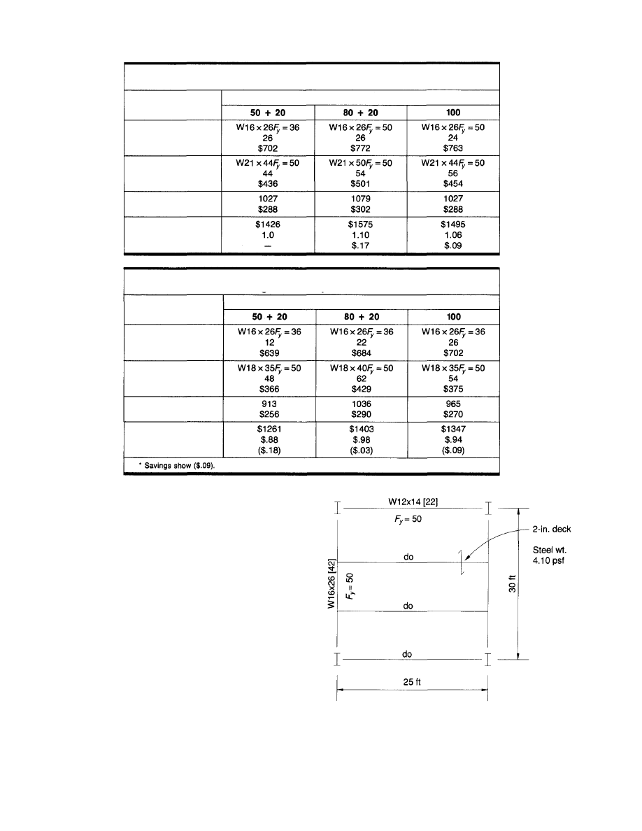
Tables 2 and 3 tabulate the comparative costs of a typical
bay floor system for the 30 ft square bay designed for the
three loadings used for the column load comparison for both
ASD and LRFD designs. The comparison is made for a dif-
ference in mill material costs and the cost of studs. The cost
of fabrication and erection remain essentially constant for
the six conditions. It is for that reason that the mill material
plus the stud costs will give a reasonably good comparison.
The cost of mill material is taken as $.25 per pound for
= 36 ksi and $.28 per pound for
= 50 ksi steels. The
unit prices for both =
36
ksi
and =
50
ksi
mill
mate-
rial change periodically. If one desires to make this type of
cost comparison, representative mill material prices may be
obtained from local fabricators. As would be expected, the
50 psf live load plus 20 psf partition load is the least expen-
sive loading condition. However, the premium for the higher
live load capacity (100 psf) condition is only $.09 per square
foot. Compared to the total cost of the structural system, the
added cost is probably less than 1%.
Knowing these facts, many owners may well wish to select
the higher live load capacity. The real difference in the struc-
tures in reality may be semantics, but as a practical matter
the higher load capacity enhances the building's value and,
most of all perhaps, its rentability.
Bay Size Selection
The selection of a smaller bay size to reduce costs may be
a fallacy when applied to steel buildings. For economy, it
is important to reduce the number of pieces to be fabricated
and erected. As noted earlier, the cost of fabrication and erec-
tion for a small beam is essentially the same as for a large
beam. The savings involved in reducing the member weight
is primarily savings in the cost of mill material. When the
number of pieces is reduced, the actual cost of fabrication
2
111½%
© 2003 by American Institute of Steel Construction, Inc. All rights reserved.
This publication or any part thereof must not be reproduced in any form without permission of the publisher.
and erection is reduced. To make a cost comparison of dif-
ferent bay sizes or beam spacings, the cost of mill material,
fabrication, and erection must be considered. To illustrate
this point we have obtained real prices from two fabricators
(one east coast, one midwest) for the four bays shown in Figs.
2 through 5. Table 4 tabulates the relative square foot costs
for the selected bays. The LRFD Specification was used to
design the members. Absolute minimum sizes were selected
for the comparison. In particular, the selection of the W12x14
for the 25 ft bay may not be realistic. It is assumed that the
beams are shored or cambered as required. Tabulated costs
include the structural steel frame, steel deck, and headed steel
studs in place ready for concrete.
Scheme I (Fig. 2) is a 25 ft square bay designed for a 100
psf live load and 65 psf dead load. The unit weight of the
steel is 4.10 psf. The total cost per square foot for the typi-
cal bay structural steel, headed studs, and composite steel
deck is $5.15 per square foot. This value is used as the base
price percentage (100%) for the comparison. This cost is not
representative for the total cost of the building frame provi-
Fig. 2. 25 ft x 25 ft bay.
3
Table 2.
Framing Cost Comparison—ASD
Loading
Section
Filler BM
Studs
Cost
Girder
Studs
Cost
Ave. col. wt/story
Cost
Total cost
Relative cost
Premium
Table 3.
Framing Cost Comparison—LRFD
Loading
Section
Filler BM
Studs
Cost
Girder
Studs
Cost
Ave. col. wt/story
Cost
Total cost
Relative cost
Premium*
© 2003 by American Institute of Steel Construction, Inc. All rights reserved.
This publication or any part thereof must not be reproduced in any form without permission of the publisher.
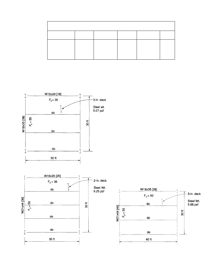
Table 4.
Percentage Comparison Square Foot Costs
Bay Size
25 x 25 ft
30 x 30 ft
30 x 30 ft (alt.)
30 x 40 ft
Mill
Material
21%
25%
31%
31%
Fabrication
& Delivery
14%
14%
16%
13%
Erection
& Studs
34%
32%
35%
33%
Composite
Deck
31%
32%
31%
32%
Total
100%
103%
113%
109%
sions for non-typical framing, spandrel conditions, and lateral
load resistance systems have not been included.
Scheme II (Fig. 3) is a 30 ft square bay designed for the
same loads as Scheme I. The unit weight for the steel is
5.07 psf and the cost is 103% of the base price. The 30 ft
Fig. 4. Alternate 30 ft x 30 ft bay.
bay provides more flexibility in planning. Office modules
of 10, 15 and 20 ft can be intermixed without column inter-
ference. The piece count is lower, that is, there are 180 square
feet per steel member as compared to 125 square feet for
the 25 ft bay. With the fewer pieces the job is more desirea-
ble in the eyes of a fabricator and erector. When the final
markup is placed on a project, the bid price for the 30 ft
square bays may well be below that for the project with the
25 ft bays. In any case, the indicated increase in cost of 3%
is a small price to pay for the added flexibility.
Scheme III (Fig. 4) is also a 30 ft square bay. But there
are four filler beams per bay. It is included to illustrate the
added cost of decreasing member spacing and increasing
piece count. The cost ratio is increased to 113% or 10%
greater than the bay with three filler beams. Performance
wise, there is no functional difference. Murray's (1991)
required critical damping and Galambos' (1988) floor vibra-
tion ratings are virtually the same. The added cost cannot
be justified on an engineering basis. (The floor vibration sub-
ject will be discussed further in the discussion on Open Web
Steel Joists.)
Scheme IV (Fig. 5) is a 30 ft by 40 ft bay. The unit weight
is 5.88 pounds per square foot. The steel and deck cost ratio
is 109%. Note that this is less than the cost of the 30 ft square
bay with the smaller filler beam spacing. This scheme may
be desirable where the dimension from the service core of
the building to the exterior is 40 ft. The added cost is not
Fig. 5. 30 ft
x
40
ft bay.
4
Fig. 3. 30 ft x 30 ft bay.
© 2003 by American Institute of Steel Construction, Inc. All rights reserved.
This publication or any part thereof must not be reproduced in any form without permission of the publisher.
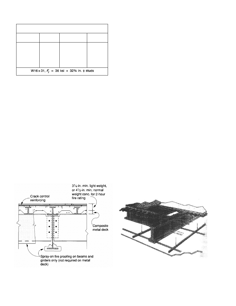
Table 5.
Live Load Capacity Enhancement
Bottom
Cover PL
None
6 x
¾
in.
None
6 x
¾
in.
9 x 1 in.
Design
Method
ASD
ASD
LRFD
LRFD
LRFD
LL Capacity
PSF
93
208
128
230
310
% LL
Increase
—
124%
38%
147%
233%
extravagant if flexibility in planning is important. When the
bay length reaches 45 ft or more, it is likely that alternate
floor systems such as stub girders or fabricated trusses may
be considered.
The selection of design live load and bay size should be
considered in the preliminary design phase of any project.
For the overall economic success of a project, the smallest
bay size and the lowest live load probably will not produce
the most economic design.
COMPOSITE FLOORS
Composite floor systems, consisting of composite metal deck
with concrete fill, steel filler beams, and girders made com-
posite by using headed stud connectors, have become a stan-
dard type of construction selected by many architects, engi-
neers, and developers (Fig. 6). Composite floor systems are
considered by many to be the highest quality type of con-
struction. The floors are stiffer and more serviceable than
open web joist systems. Adequate fire resistance ratings may
Fig. 6. Composite metal deck floor system section.
be obtained by simply providing a coat of fireproof mate-
rial on the structural shape only. The combination of the con-
crete slab (light weight or normal weight) and composite steel
deck require no additional protection when the proper slab
thickness is used for a required fire rating. Furthermore,
underfloor ducts for communications and electrification may
be included in the system (Fig. 7). The addition of under-
floor ducts adds to the cost. This added cost may be justi-
fied as the underfloor system adds significantly to the flexi-
bility in space planning and ease of leasing.
Allowable Stress Design and
Load and Resistance Factor Design
Chapter I, Composite Construction, of the AISC's "Speci-
fication for Structural Steel Buildings" (AISC, 1989) is an
allowable stress design specification (ASD) and is the stan-
dard by which composite steel beams have been designed
in the USA. This design method is based upon an elastic anal-
ysis with maximum allowable stresses specified for the con-
crete slab compressive flange and the structural steel beam
(Fig. 8). For many years the academic world has been aware
that elastic design of composite sections seriously underes-
timates their actual strength. Still, the elastic design proce-
dure has prevailed.
The 1986 AISC "Load and Resistance Factor Design Spec-
ification for Structural Steel Buildings" (AISC, 1986) is
essentially an ultimate strength design procedure which more
accurately predicts the strength of steel beams with a com-
posite concrete compression flange. Figure 9 illustrates the
two possible stress distributions for the ultimate strength
design procedure. The plastic neutral axis (PNA) may be
located either in the steel section or at the base of the com-
posite concrete flange. (Note: The base of the composite con-
Fig. 7. Cellular composite steel deck system with in-floor
electrical and communication distribution.
5
© 2003 by American Institute of Steel Construction, Inc. All rights reserved.
This publication or any part thereof must not be reproduced in any form without permission of the publisher.
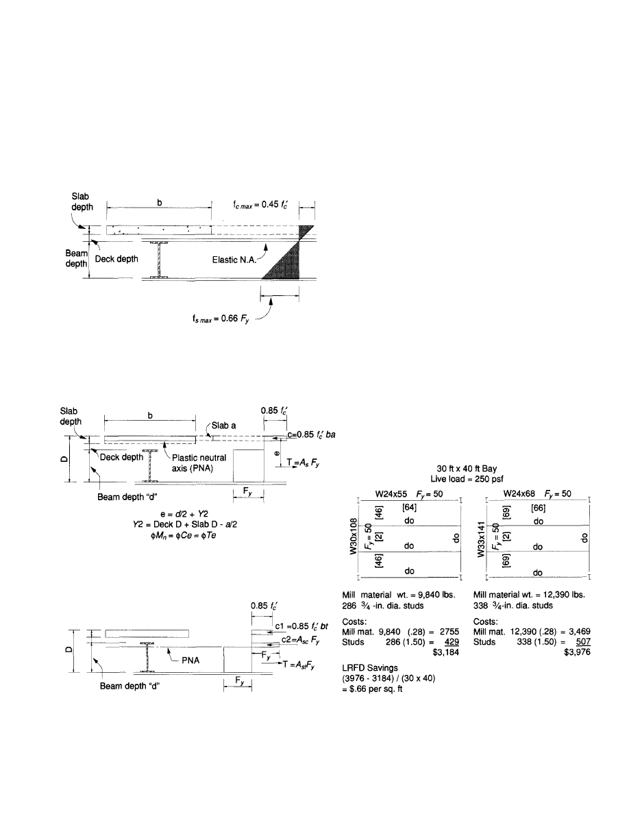
crete flange is not necessarily at the bottom of the concrete
slab.) The use of the ultimate design concept inherent in
LRFD results in an extremely simple design procedure. With
this procedure and the design aids for composite beams in
the AISC Load and Resistance Factor Design Manual (AISC,
1986a), composite beam design becomes a method that
requires little computation. An abbreviated design example
using the design aids in the AISC LRFD Manual is given
in Appendix A.
Note: The elastic neutral axis may occur in the concrete slab,
between the concrete slab and steel section or in the steel
section. When the neutral axis is in the concrete slab, no
tension is permitted in the concrete below the neutral axis.
Fig. 8. Elastic stress distribution.
Note: In this case the concrete compression flange thickness
"a" is less than the slab thickness.
(a) PNA in Concrete Slab
(b) PNA in Steel Beam
Fig. 9. Composite beam stress distribution.
Economy with LRFD
The use of the ultimate strength design procedure with the
LRFD Specification often results in some saving of mill
material. Figure 10 indicates the beam and girder sizes
required for a typical bay with a 250 psf live load warehouse
loading for both the LRFD and the ASD design methods.
In this case, the use of LRFD results in a savings of about
20% in the cost of mill material to the fabricator or $.60 per
square foot and a savings of about $.065 per square foot in
the cost of headed studs. The cost of mill material and headed
studs are assumed to be $560 per ton ($.28 per lb.) and $1.50
each (installed), respectively. Note that the cost of fabrica-
tion and erection does not change—the saving is simply the
cost of the raw mill material and stud cost. The saving is
significant and can materially reduce the cost of a project.
The use of lighter weight beams will result in greater deflec-
tions which must be considered. The use of lighter weight
beams will not result in a higher potential for vibration prob-
lems due to pedestrian foot traffic.
Floor Load Capacity Enhancement
From time to time it becomes necessary to increase the load
capacity of an existing floor system. Sometimes, office build-
ings are designed for the prescribed loading of the local
building code with provisions made for live load capacity
increases to suit tenants' needs in specific areas. Composite
floor systems offer a means by which floors may be designed
for the code specified floor load and upgraded to a much
higher capacity for storage or high density filing systems.
With composite construction, floor load capacity enhance-
ment is a relatively simple matter. Some designers select
(a) LRFD
(b) ASD
Fig. 10. Typical warehouse bay plans.
6
© 2003 by American Institute of Steel Construction, Inc. All rights reserved.
This publication or any part thereof must not be reproduced in any form without permission of the publisher.
special areas for this type of live load enhancement. Col-
umns are designed for the anticipated increase in loading.
Filler beam connections are designed for the increased load-
ing. The increase in load capacity may be achieved at a later
date by simply welding a cover plate to the bottom flange
of the filler beams.
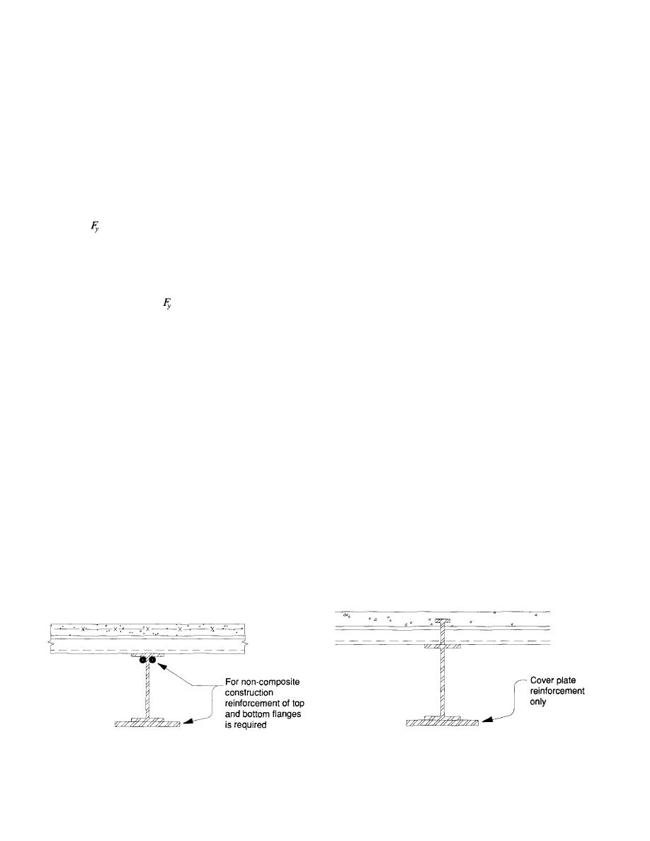
To appreciably increase the capacity of non-composite
beams and girders, it is necessary to add reinforcement near
both the top and bottom flanges (Fig. 11). On the other hand,
for compositely designed beams and girders a significant
increase in load capacity can be achieved simply by adding
a cover plate to the bottom flange (Fig. 12). Consider a
W16x31, =
36
ksi
composite filler beam with thirty-two
¾ -in. round headed shear studs, spanning 30 '-0" and spaced
at 10 '-0" o.c. Calculations based on an assumption of a 100
psf live load and 60 psf dead load, the 1987 BOCA Building
Code (BOCA, 1987) with its live load reduction provisions
and spanning 30 '-0" and spaced at 10 '-0 " o.c. will result in
the selection of a W16x31, =
36
ksi
with
thirty-two ¾-in.
round headed studs. Table 5 indicates the live load capaci-
ties for both ASD and LRFD designs and the increase in
capacity obtained by the addition of two sizes of cover plates
to the bottom flange of the W16x31. The increase in live load
capacity of the W16x31 with a 6-in. x ¾-in. cover plate is
147% (LRFD) and 124% (ASD) above the original design
live load. A 50% addition in steel results in a 100% increase
in live load capacity. The W16x31 plus a 9-in. x 1-in. cover
plate is shown to indicate the upper bound moment capacity
of the composite section. In this case, the thirty-two ¾-in.
diameter headed studs are the limiting factor. The 9-in. x
1-in. cover plate is included only to illustrate the magnitude
of capacity enhancement possible. Limitations in connection
capacity or web shear strength may well be the determining
factor. Computation examples for composite beam capacity
enhancement are included in Appendix B.
Shored vs. Unshored Construction
Designers of composite floor systems face a difficult choice
in specifying whether shored construction should or should
not be used. There seems to be no evidence that either
scheme is clearly superior to the other.
Fig. 11. Simple beam load capacity enhancement.
Unshored construction
The selection of an unshored system simplifies the work of
the contractor. The wet concrete is simply placed on the com-
posite metal deck after the studs and slab reinforcing are in
place. But, for this condition, there are additional factors
which must be considered by the design engineer. The floor
beams and girders must be designed to support the wet load
condition loads as non-composite sections. If the beams and
girders are not cambered, the designer must consider the load
due to the additional concrete required as a result of the
deflection of the steel beams and girders. Ruddy suggests
that even though the theoretical volume of concrete due to
the ponding effect may be substantial, the actual increase
in volume appears to be near 10%. For very light beams with
high span/depth ratios, this figure may be unconservative.
If camber is specified for the beams and girders, a different
problem may be encountered. If the placement sequence of
the plastic concrete is such that the system deflection is less
than the specified camber, slabs thinner than that specified
and headed studs with less than the required coverage may
result. This could lead to floor systems with less than the
required design strength. Some designers specify cambers
equal to three-quarters of the theoretical wet load deflection.
For moderate sized beams, cambering is reasonable if the
fabricator uses a cambering machine. Some designers omit
camber and design the system for a slab weight 10% to 15%
greater than the theoretical weight and specify that the floor
be poured flat.
Shored construction
Two advantages of shored construction are: (1) all of the
deflections are based on the composite section; and (2) a
strength check of the steel section alone is not required for
the wet load condition. The elimination of the requirement
for the wet load strength condition is significant for low live
load/total load ratios. One disadvantage of shored construc-
tion is that a formation of a crack over the girders is almost
certain. It is prudent that the designer specify crack control
reinforcement over the girders (Fig. 6) for both shored and
unshored construction. However, it is especially important
for shored construction. Some designers feel that crack con-
Fig. 12. Composite beam load capacity enhancement.
7
© 2003 by American Institute of Steel Construction, Inc. All rights reserved.
This publication or any part thereof must not be reproduced in any form without permission of the publisher.
trol reinforcement should also be placed in the top of the
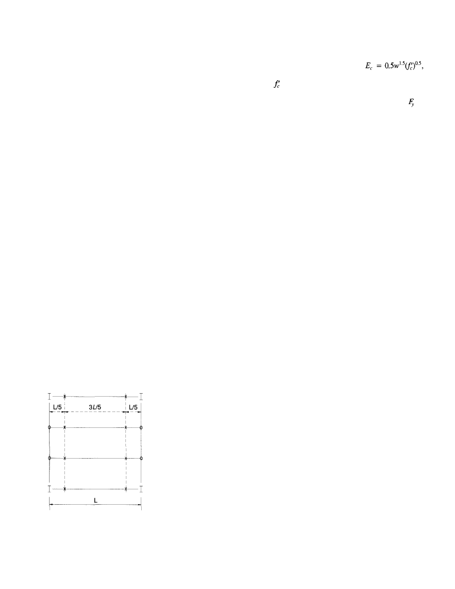
slab over filler beams. A shoring scheme which minimizes
the amount of shoring required and yet controls the deflec-
tion is illustrated in Fig. 13. By placing the shores at the
1
/
5
points of the span, the moment in the supporting composite
beams and slabs are reduced and the deflection of the shored
beams is minimized. The girders below the floor being
poured may be shored at the load points to spread the wet
concrete load to two floors during the placement of the con-
crete. Shored or unshored construction is also a matter of
cost consideration. For any specific project, the construc-
tion manager or general contractor should be consulted, if
possible.
Serviceability Considerations
Three serviceability items will be considered:
1. Floor vibration induced by foot traffic
2. Floor deflection
3. Crack control
Under certain conditions, composite floor systems can be
subject to unpleasant vibrations induced by pedestrian foot
traffic. These areas can be generally categorized as being
large open areas without finishes and/or furnishings which
will help provide damping of the system. The work of Mur-
ray and Galambos (Galambos 1988; Murray 1975, 1991; Mur-
ray, Hendrick 1977) will be helpful in gaining understand-
ing of the subject.
Deflections in composite systems will vary with the type
of construction. For unshored systems, the deflections due
to the entire wet load will be time independent and will not
increase with time. For shored systems, the initial wet load
deflection will be subject to increase due to creep and shrink-
age in the concrete compression flange. In addition, for both
systems, deflections due to the weight of the finishes and
average total live load will also be subject to increase due
to creep and shrinkage of the concrete. One method of
"X" indicates location of
shores below filler beam on
floor which is being poured.
"O" indicates location of
shore below girders on floor
below floor which is being
poured.
Warning: Filler beam shores
should remain in place until
concrete has reached 75%
of the design strength.
Loads on filler beams
supporting shores should be
checked for strength.
Fig. 13. Shoring plan.
accounting for creep and shrinkage is to use the modulus
of elasticity of the concrete to be one half of its normal value.
That is, take the modulus of elasticity
where w is the unit weight of the concrete in pounds per cubic
foot and
is the concrete cylinder strength expressed in
kips per square inch. Appendix A contains long-term deflec-
tion calculations for a standard filler beam W16x31 =
36 ksi with thirty-two ¾-in. diameter headed studs spanning
30'-0" and spaced 10'-0" o.c. For this composite section,
the moment of inertia for short-term loading is 1400 in.
4
and is decreased by 15% to 1185 in.
4
for long-term loading.
For the unshored system, the wet load deflection is equal
to 0.9 in. Taking the weight of the finishes to be 9 psf and
a permanent average live load of 10 psf, the long-term deflec-
tion will be an additional 0.10 in. For the shored system, the
long-term deflection due to the wet load finishes and an
assumed permanent live load of 10 psf will be 0.37 in.
As noted earlier, it is desirable to provide crack control
reinforcing in the concrete slab over the top of girders. For
shored systems, when the shores are removed, it is almost
certain that cracks will form over the girders. Crack control
reinforcing will help distribute and limit the size of the cracks.
Due to the nature of composite construction, cracking in the
top of the slab over the supports is likely to occur before
composite action is activated. Most composite slab systems
are designed using an ultimate strength mechanism which
neglects any negative bending moment at the supports. An
unreinforced slab is likely to crack over the supports when
real loads are applied. In addition, some slippage between
the concrete and steel section may occur before the steel and
concrete can act compositely. For high live load applications
and/or for systems subject to moving loads such as lift trucks,
it is prudent to design these slabs with top reinforcing to
assure that the performance of the slab will be acceptable
in the long term.
Underfloor Duct Systems
An underfloor duct system using cellular floor deck units
is a system often selected by users, owners, and developers
to provide virtually unlimited flexibility in the planning of
office building floor space (Fig. 7). The use of this system
provides a tenant access to a building's electric power and
communication systems in the floor. Generally, the cellular
deck units are blended with regular composite metal deck
units to provide underfloor duct runs at regular intervals. Fig-
ure 14 illustrates a blend of two 3 '-0" wide composite deck
units and a 3 '-0" wide cellular deck unit. This blend results
in a 9 '-0 " spacing for the duct runs. Other spacings can be
obtained by varying the widths of the units and/or the num-
ber of cellular and composite deck units. Cellular deck sys-
tems are not commodity items. Their capabilities, capaci-
ties, etc., vary with different manufacturers. However,
comparable systems are available from different manufac-
turers for competitive bidding.
8
© 2003 by American Institute of Steel Construction, Inc. All rights reserved.
This publication or any part thereof must not be reproduced in any form without permission of the publisher.
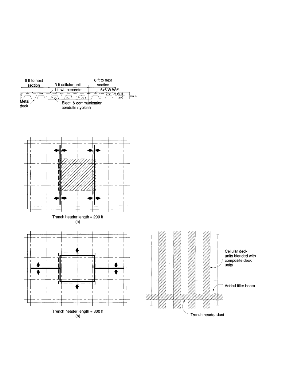
The use of underfloor duct systems with cellular deck
requires additional design considerations by the architect-
engineer team. It is important to orient the cells and trench
headers to minimize the length of the trench headers. Fig-
ures 15a and 15b illustrate two possible solutions for a typi-
cal office building layout (100' x 180'). The plan shown in
Fig. 15a results in a trench header length only two-thirds of
Fig. 14. Blended metal deck floor.
Fig. 15. Trench header and cellular deck plans.
9
that for the plan shown in 15b. The savings is substantial
($.15 to $.20 per square foot).
For a typical office building floor, a two-hour required fire
resistance rating may be obtained by using a 3¼-in. mini-
mum thickness lightweight concrete slab on a composite
metal deck without additional fire protection. However, the
cellular deck units used for ducts must be protected with an
applied fireproofing material. An alternate solution to the
lightweight concrete slab is the use of a 2½-in. minimum
thick normal weight concrete slab with a sprayed-on coat
of fireproofing material. The most economical selection of
systems may be dependent upon the blend of composite and
cellular deck units.
The introduction of cellular deck units and the accompany-
ing trench headers require special structural considerations.
The presence of the trench headers impacts upon the design
of the composite floor deck units, the filler beams and the
girders. The passing of the trench header over the compos-
ite deck causes the composite slab to be ineffective. There-
fore, the deck must be designed to carry the gravity load with-
out the composite slab contribution. An additional filler beam
may be introduced as shown in Fig. 16. Filler beams adja-
cent to the trench header must be designed for the condition
of the slab on one side of the beam only. If filler beams are
not placed on each side of the trench duct, the deck units
themselves must be designed as non-composite sections.
Also, if filler beams are not located on each side of a trench
header, the slab stiffness is reduced in that span and the floor
may feel "soft" or "spongy." It is likely that the girder beams
will have to be designed as non-composite since the trench
header interrupts the composite slab and substantially reduces
the physical space for studs.
Fig. 16. Added filler beam at trench header.
© 2003 by American Institute of Steel Construction, Inc. All rights reserved.
This publication or any part thereof must not be reproduced in any form without permission of the publisher.
OPEN WEB STEEL JOIST FLOOR SYSTEMS
Open web steel joist floor systems are used for commercial
and residential projects (Fig. 17). The very large volume of
floor area built annually, estimated to be in the tens of mil-
lions of square feet, suggests that the economics associated
with their use overcomes any perceived serviceability short-
comings. The Standard Specifications and Code of Standard
Practice are published by the Steel Joist Institute of Myrtle
Beach, South Carolina (SJI 1986).
Joist Size and Spacing
The selection of the most economical joist for any given sit-
uation will generally be the deepest and lightest joist at the
widest space permitted by the slab thickness. The use of joist
spacings of 3 '-0 " or more should be considered. The decrease
in the number of pieces results in heavier, more efficient sec-
tions and perhaps a reduction in the number of lines of bridg-
ing. Also, the reduction in the number of pieces to be fabri-
cated and erected may well offset the added cost of a slightly
thicker concrete slab. The performance of the floors with
thicker slabs subjected to vibrations induced by pedestrian
foot traffic is significantly superior (see Floor Vibrations).
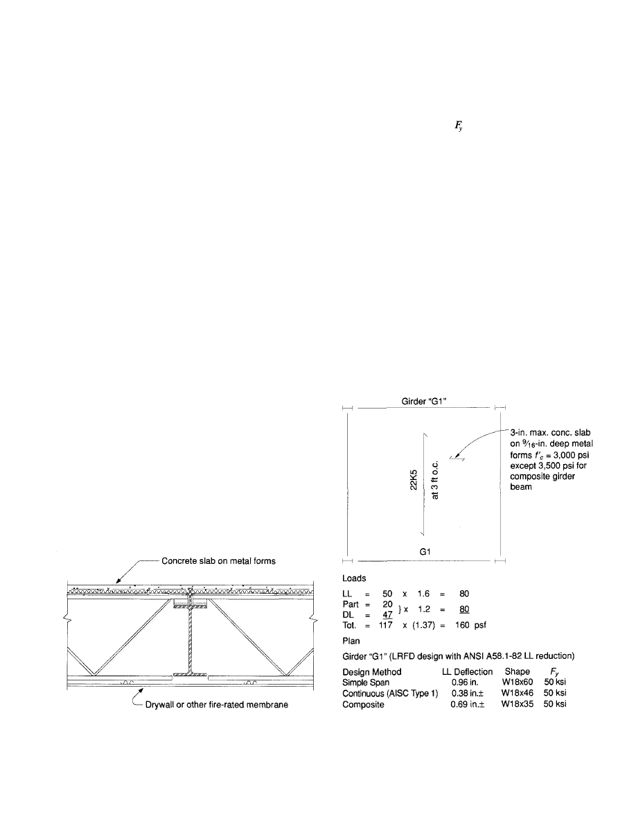
Girder Beam Design
Girder beams supporting open web joist floor systems are
normally designed as simply supported beams. In applica-
tions where it is desirable to use a floor-ceiling assembly to
obtain a fire rating (Fig. 17), it may be economical to con-
sider the use of continuously designed girder beams or com-
positely designed girder beams to minimize the required
girder beam depth and weight. For example, Fig. 18 illus-
trates a typical office floor bay with girder beams designed
as simply supported, continuous design (ASD Type 1 con-
struction, LRFD Type FR construction), and composite
girder beam design. Abbreviated calculations for the girder
beams are included in Appendix A. The depth of the selected
girders is limited to 18 in. to allow the ceiling fireproofing
Fig. 17. Fire-rated floor ceiling assembly.
10
membrane to pass under the girder uninterrupted. The tabu-
lated live deflections are computed with reduced live loads.
However, the 20 psf partition load is included, as they may
be moved from time to time. The simple beam deflection
(0.96 in.) is marginal and may be unacceptable to some
designers. In that case, if
= 36 ksi mill material was to
be specified, the size girder beam required would be a
W18x76. The W18x76 would have a live load deflection of
0.71 in. If the continuous beam is to be selected, to be eco-
nomical the difference in cost of the mill material plus the
difference in cost of the connections (both shop and field)
must be considered. A patented composite girder system
which was described in an AISC Engineering Journal arti-
cle may be considered and could prove to be economical
(Rongoe 1984). Figure 19 illustrates the composite system.
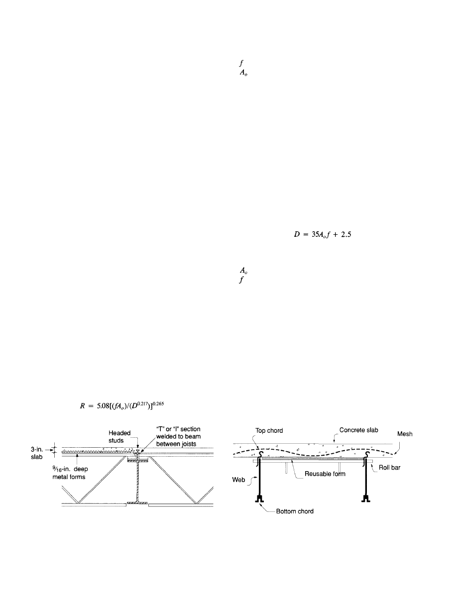
Composite Joist Systems
Composite joist systems are widely used and very competi-
tive in some areas. Systems vary with different manufac-
turers. One widely known system is produced by Canam
Hambro Systems Inc. of Baltimore, Maryland. Joists are
evenly spaced to accommodate 4 '-0" wide plywood form
material which is supported on removable clips. After a rein-
forced concrete slab is cast, the forming material is removed
for reuse (Fig. 20).
Fig. 18. Typical bay girder beam comparison.
© 2003 by American Institute of Steel Construction, Inc. All rights reserved.
This publication or any part thereof must not be reproduced in any form without permission of the publisher.
Floor Vibration
Open web steel joist floor systems as well as some other floor
systems with large open spaces lacking partitions and/or other
loads can be subject to disturbing vibrations induced by
pedestrian foot traffic. Span lengths less than 20'-0" or
greater than 35 '-0" seldom experience pedestrian traffic-
induced vibration problems except for long-span floor sys-
tems with low natural frequencies. On the other hand, floors
which support partitions and/or other furniture or equipment
normally perform well and do not exhibit poor behavior. At
this time there is no universally accepted method that can
be used to evaluate this problem. The work of Murray (1975,
1981, 1991), Murray and Hendrick (1977), and Galambos
(1988) include design methods which can be used to calcu-
late floor vibration ratings.
A method of evaluating the performance of open web joist
systems subject to foot traffic is contained in the Steel Joist
Institute publication Vibration of Steel Joist-Concrete Floor
Slabs by Galambos (1988). The method is especially suited
for joist floors and has been used in the preparation of the
floor ratings discussed herein. A number of different criteria
have been proposed for use in evaluating the vibration prob-
lem. Murray (1981) has reviewed many of the proposed
methods and found that the results of the different methods
often conflict. Two of the methods will be discussed, one
that is described in a Steel Joist Institute publication
(Galambos 1988) and the method proposed by Murray in
"Acceptability Criterion for Occupant Induced Floor Vibra-
tions" (1981) and "Floor Vibrations" (1991). An ASCE
report, "Structural Serviceability: A Critical Appraisal and
Research Needs" (ASCE 1986), proposes an acceptance
criterion which is similar to and derived from Murray's work.
The SJI publishes a booklet by Galambos, Technical Digest
No. 5, Vibration of Steel Joist Concrete Floors (1988). This
publication has recently been updated (March 1988) and
includes information for use in designing floors subjected
to dancing, running, and similar rhythmic activities. Floor
vibration ratings are computed by the formula suggested by
Wiss and Parmelee (1974):
Fig. 19. Composite beam with open web steel joists.
11
where
= natural frequency, cps
= amplitude, in.
D = % of critical damping
The SJI's suggested criteria for floor ratings is as follows:
R = 2.5
vibration is barely perceptible
R = 3.5 vibration is distinctly perceptible
R = 4.5 vibration
is strongly perceptible
These values are more liberal than those suggested by the
original Wiss and Parmelee paper (1974). Galambos also
includes calculations for acceptance as judged by Murray's
criterion as discussed below.
The work of Murray (1975, 1981) and Murray and Hen-
drick (1977) is thought by some engineers to be the most reli-
able information available on this subject. Murray's criterion
for acceptance is much simpler. Murray states that a more
accurate division of acceptable and unacceptable floor sys-
tems is given by
where
D = percent of critical damping
= initial amplitude from a heel drop impact, in.
= first natural frequency of the floor system
This method is simple to use for the designer as the result
is a lower bound value for the percent of critical damping
required. Murray's 1981 criterion is based on a study of the
test results of 91 floor systems. Some engineers feel that Mur-
ray's criterion gives better results over a wide range of floor
systems.
In some ways, the design to control vibrations is paradox-
ical. For instance, if a beam is made heavier to increase its
stiffness, often the frequency increases at a higher rate than
the amplitude decreases. As a result, the floor rating R and
the percent of critical damping required D increase rather
than decrease. Increasing the beam size to help reduce vibra-
tions can result in a worse condition. Vibration problems vary
inversely with the span length. As span lengths increase, the
Fig. 20. Composite steel joist floor system.
© 2003 by American Institute of Steel Construction, Inc. All rights reserved.
This publication or any part thereof must not be reproduced in any form without permission of the publisher.
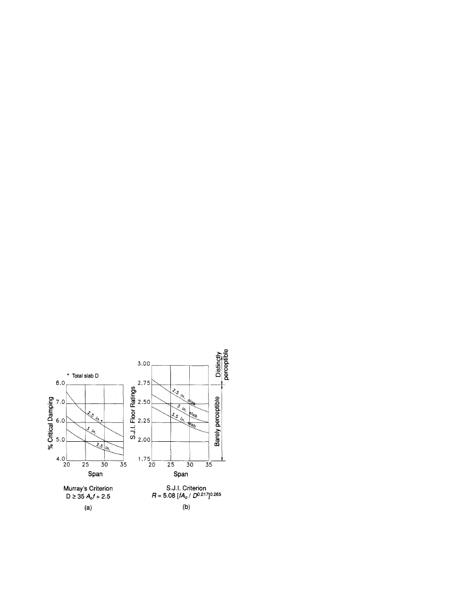
floor ratings and the required damping both decrease. Steel
filler beam and joist floor systems with spans of 20 ft and
less are not subject to vibration problems. Figure 21 plots
both Murray's requirement for critical damping and the SJI's
suggested ratings for three slab thicknesses. The SJI ratings
were calculated using a critical damping ratio of 0.04. A num-
ber of joist sizes and spacings were used to calculate the rat-
ings. It was determined that the ratings are not a function
of joist size or spacing. It can be observed that the required
damping and the SJI floor rating both decrease rapidly with
an increase of span or slab thickness.
Similarly, as spans increase and natural frequencies
decrease below 3.0 hz, vibration problems can become
severe. For instance, a floor with 52DLH joists spanning
90 '-0 " at a 3 '-0 " spacing with a 3-in. concrete slab on metal
forms and with a total load of 100 psf (30 ambient psf LL
plus 70 psf DL) has a natural frequency of about 2.6 cps and
a floor rating of 1.97 with 4% damping. Seemingly, this
would be an acceptable floor system using the Wiss, Par-
melee rating method. However, a repetitive loading match-
ing this natural frequency (such as fast dancing) can lead to
disastrous results. Thus, for long span floors for places of
assembly where such a moving load can be expected, it may
be prudent to make a vibration analysis and, when indicated,
provide some positive damping. Both the SJI Digest
(Galambos 1988) and the ASCE Ad Hoc Report (ASCE
1986) address this subject.
Fig. 21. Steel joist floor vibration ratings.
12
WIND LOAD DESIGN
The structural design of systems to resist wind loads is one
of the most interesting tasks that a structural engineer can
encounter in his career. The number of possible solutions
are endless. This is the area in which one's imagination and
judgment can be used in the development of innovative
designs and to find unique solutions to the most important
and difficult problems in the design of high-rise buildings.
For structural engineers, the goal for wind load design might
be defined as to produce structures that perform in a satis-
factory manner under the influence of wind loads and, as
always, at the least possible cost. The level of performance
desired may vary with the type and use of the structure. For
instance, a higher level of performance would be desirable
for a hospital than for a speculatively built office building.
In a hospital environment, it is probably not acceptable for
the occupants to feel uncomfortable due to motion induced
by wind load except under extraordinary circumstances. On
the other hand, the owner of a speculative office building
may well accept some disturbing motion on a more or less
regular basis, say five or ten years. Galambos and Elling-
wood (1986) suggest that an acceptable level of performance
may be to expect some occupant annoyance one time in the
life of an average lease—eight years. Thus, it may seem
appropriate to establish separate levels of performance for
strength and serviceability for different types of structures.
For a hospital, one may wish to select a 100-year storm for
strength and a 50-year storm for motion. For an office build-
ing, one may wish to use the code-required wind load
(usually 50 years) for strength and a 10-year storm for
motion. In any case, the deflection due to wind load must
be limited to an amount that the building cladding and fin-
ishes can tolerate.
Drift Limits
The selection of an appropriate drift limit for a multi-story
project is a problem faced by structural engineers since the
inception of skyscrapers. It is now recognized that drift con-
trol will not necessarily insure satisfactory performance with
respect to human perception of motion due to wind loading.
In tall buildings (buildings over 300-350 ft), acceleration due
to wind loading is the parameter which must be considered
in evaluating the effects of wind-induced motion. For build-
ings under 25 to 30 stories, drift control will probably become
more important in the near future. At this time full wind tun-
nel studies are probably not economically justified for the
less tall buildings. Two references which describe the prob-
lem are "Structural Design of Tall Steel Buildings" (CTBUH
1978) and "Human Response to Tall Buildings Wind-Induced
Motion" (Reed, Hansen and Van Marke 1972).
Historically, recommended drift limits have varied widely
(CTBUH 1979). Recently, a subcommittee of the ASCE Com-
mittee on Design of Steel Building Structures conducted a
© 2003 by American Institute of Steel Construction, Inc. All rights reserved.
This publication or any part thereof must not be reproduced in any form without permission of the publisher.
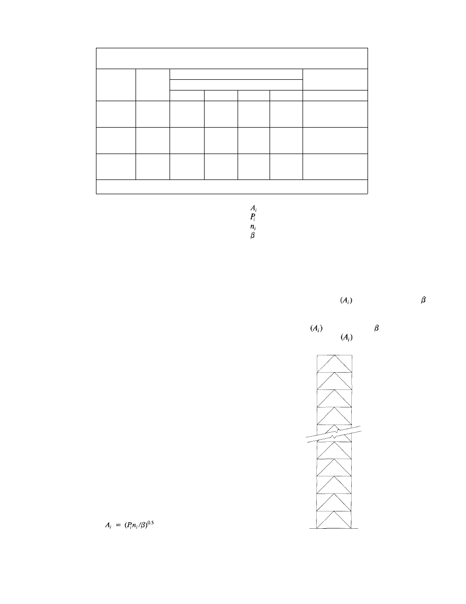
Table 6.
Optimum Stresses for K-Braced Frames
No. of
Stories
10
HT=125
20
HT = 250
30
HT = 375
Aspect
Ratio
5/1
7.5/1
10/1
5/1
7.5/1
10/1
5/1
7.5/1
10/1
Column Stress
Floor
Bot.
¼
10.1
8.1
6.5
8.2
7.4
6.3
6.8
6.6
4.6
2nd
¼
8.9
7.1
5.7
7.2
6.8
5.5
5.9
5.8
4.0
3rd
¼
7.2
5.7
4.6
5.8
5.4
4.4
4.7
4.6
3.2
Top
¼
7.1
4.5
3.6
4.0
4.2
3.1
3.1
3.0
2.1
Web Stress
Multiplier
Girder and Brace
1.36
1.36
1.36
1.36
1.36
1.36
1.36
1.36
1.36
BOCA basic building code— wind speed 70 mph. Apex of "K" bracing up.
poll of structural designers to determine the state of the art
for wind load design (ASCE 1988). The report of the Task
Committee includes not only the results of the poll but, in
addition, its comments on and interpretation of the results.
The results of the poll are at best ambiguous. However, in
answer to the question, "Which drift limit would you use?"
for a total of 34 different building types and exposures, the
predominant answer was 0.0025 for wind service load
(deflection/height). However, the committee did not make
any recommendations for drift limits.
In addition to drift control for human occupancy concerns,
the effect of drift on cladding elements must be considered.
Cladding connections to the building frame should be
designed to accommodate the wracking deflection to which
it will be subjected. The deflection characteristics of braced
and unbraced frames is briefly discussed in the Combina-
tion Frames section.
Braced Frames
Braced frames are often the most economical method of
resisting wind loads in multi-story buildings. However, the
use of bracing bents alone can result in very large uplift forces
even in moderately low high-rise buildings (10-15 stories).
This may not be a problem if deep foundations which can
resist uplift are used. The use of bracing frames combined
with other systems such as hat or belt trusses can be very
efficient as shown in Fig. 30 (see Combination Bracing
Systems).
The design of pin-connected K-braced frames (Fig. 22)
with optimum sizes is easily performed using a method sug-
gested by Baker (1987) of the Chicago office of Skidmore,
Owings & Merrill. Similar methods have been used by other
engineers.
Using a classical work method, Baker has suggested that:
where
13
= optimum area of bracing frame member
= bar force in member i due to external load
= bar force in member i due to virtual load
= unknown parameter
The procedure to find the optimum areas is as follows:
1. Calculate bar forces in members due to external loads.
2. Calculate bar stresses in members due to a virtual unit
load placed in the location and in the direction at a point
where the deflection is to be optimized.
3. Compute member areas
using the value for
equal to one.
4. Compute the deflection at the point of the virtual load
using the areas computed
with
equal
to
one.
5. Modify the member areas by
multiplying them by
Fig. 22. K-braced bent.
© 2003 by American Institute of Steel Construction, Inc. All rights reserved.
This publication or any part thereof must not be reproduced in any form without permission of the publisher.

the ratio of the target deflection to the calculated deflec-
tion computed with
equal to one.
An example is shown in Appendix A. The design exam-
ple set up in a tabular form with consecutive columns of cal-
culations. A target Deflection Index (DI) of 0.0025 was
selected. For simplicity, a uniform wind load of 10 kips per
floor was used. The tabular columns are numbered and
named with a mnemonic which can be used as a variable
in a computer program. The algorithm used to compute the
truss deflection is similar to that which is illustrated in "Plas-
tic Design of Braced Multistory Steel Frames" (AISI, AISC
1968). It should be noted that the final areas are optimized
for deflection only. All members must be checked for strength
for all loading conditions. Undoubtedly, optimized areas for
members in the upper stories will be less than those required
for strength. This will result in final deflections being smaller
than the target DI. Although of limited value, this same
method can be used to find optimum areas for deflection
limits for any pin-connected truss system.
It is important to keep the apex of the bracing members
pointed in an upward direction. The deflection of a frame
with an aspect ratio (building height to width) of 7.5/1 for
a 10-story building, using the average stresses tabulated in
Table 1, results in a maximum deflection of 3.8 in., a deflec-
Fig. 23. Wind frame deflection comparison.
tion index (DI) of 0.00253. The same frame with the apex
of the braces pointed in a downward direction results in a
maximum deflection of 5.11 in., DI = 0.00341 (Fig. 23). This
is an increase in deflection of 35% due merely to the change
in orientation of the bracing members. With the apex of the
braces up, the story drift due to chord drift (column strain)
in that story is eliminated. Figure 24 illustrates the deflec-
tion of a single story in a frame due to column strain. In
Fig. 24a the apex of the braces point up. The force in the
columns due to the story shear in that story is zero. All of
the story shear load is taken by the brace members. There
is no column strain, story rotation, or deflection due to col-
umn strain. In Fig. 24b the braces point down. As a result,
Fig. 24. K-brace frame deflection due to column strain.
14
© 2003 by American Institute of Steel Construction, Inc. All rights reserved.
This publication or any part thereof must not be reproduced in any form without permission of the publisher.
the columns are subjected to axial loads. These axial loads
produce column strain, story rotation, and story deflection.
At any floor level above, deflection at the higher elevation
is increased due to the story rotation of the lower floor which
is equal to the distance above the lower floor multiplied by
the lower story rotation. This phenomenon is less pronounced
in higher frames.
Unbraced Frames
A method for the direct design of unbraced frames is illus-
trated. The method is applicable to a wide range of frames,
providing that the members are arranged and proportioned
as stipulated. This method can use either ASD (AISC 1978)
or LRFD (AISC 1986) design specifications. The LRFD
specification is better suited for the method. The following
material is based upon use of the LRFD specification.
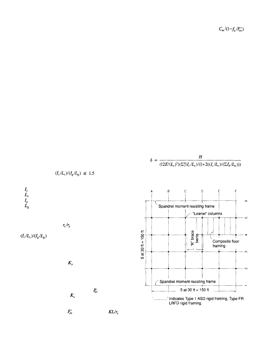
There are two stipulated design requirements. First, the
number of load resistance frames should be minimized. Fig-
ure 25 represents a framing plan for a typical office build-
ing which will be used for a design example that follows.
Spandrel moment resisting frames have been selected to resist
east-west wind loads. This reduces the number of rigid frame
connections for economy. Spandrel framing permits the
selection of deeper and more efficient girders. Second, select
the ratio of column to girder stiffnesses to be less than or
equal to 1.5, that is:
where
= column moment of inertia (major axis)
= column length
= girder moment of inertia (major axis)
= girder length
The "K" bracing frames shown in Fig. 25 are designed
to provide for the lateral loads in the north-south direction.
The minimum ratio of
is greater than 1.5 for all com-
monly used rolled column shapes. If the ratio of
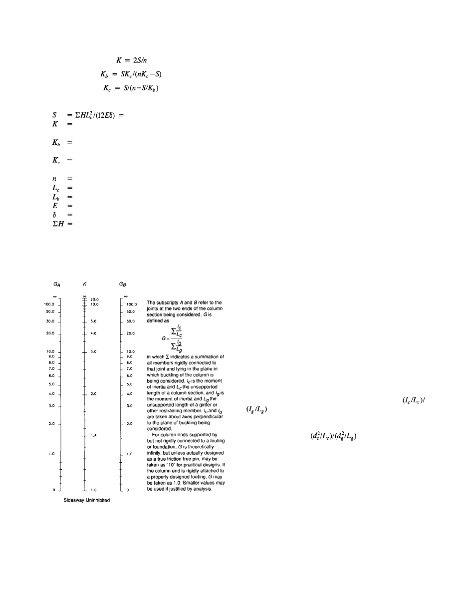
is kept below 1.5, the resulting effective
length factor K from the alignment chart in the Steel Man-
ual (AISC 1989) will also be less than 1.5. In the design exam-
ple the required stabilizing forces in the north-south direc-
tion will be provided by the "K" braced bents. The
north-south wind frames
will equal one. The required
stabilizing forces could also be provided by a properly
designed moment resisting frame. There is no need to com-
pute the effective length factor K, since for unbraced frames
when using the P-Delta method contained in the LRFD Spec-
ification (Formula Hl-5) as the value of
is calculated for
the effective length factor
equal to one.
The proposed method can be used with both the ASD and
LRFD specifications. The use of ASD is not as economical
for two reasons. In ASD, is
calculated
using with
the factor K > 1.0 as specified by Sect. 1.8 of the ASD spec-
ification, and the moment magnifier is
applied to both gravity (non-sway) and wind (sway) moments.
On the other hand, for LRFD there are separate moment
magnifiers for non-sway and sway moments. In non-
symmetrical frames there may be significant sway moments
due to gravity loads which must be considered in the design.
And, finally, using LRFD, the governing load factors for
unbraced frames will normally be:
1.2D
+ 1.6L + 0.5S
1.2D
+ 1.3W + 0.5L + 0.5S
The reduction of the load factor for live load from 1.6 to
0.5 when combined with wind is significant. Many columns
for which the critical loading would have been wind plus
gravity, using ASD, will be selected with the gravity only
loading (no wind) being critical, using LRFD.
The following design procedure and design example will
be made in accordance with the requirements of the LRFD
specification.
The key step in the procedure is the computation of mini-
mum member moments of inertia to control drift to a speci-
fied target deflection index (DI). From the traditional story
deflection formula:
Fig. 25. Typical office building plan.
15
© 2003 by American Institute of Steel Construction, Inc. All rights reserved.
This publication or any part thereof must not be reproduced in any form without permission of the publisher.
the following can be derived:
(1)
(2)
(3)
where
stiffness factor
required average I/L values for beams and columns,
in.
4
required average beam I/L values for known values
of average column I/L values, in.
4
required average column I/L values for known
values of average girder I/L values, in.
4
number of bays
story height, in.
beam length, in.
modulus of elasticity, ksi
story deflection, in.
total tributary story wind shear, kips
Equations 1, 2, or 3 can be used to determine the average
stiffness of all frame members to control drift to a specified
Fig. 26. Alignment chart for effective length of columns in
continuous frames.
16
deflection selected by the designer. This is referred to as the
target DI.
A step-by-step procedure is as follows:
1. Compute wind girder size for gravity loads and the
accompanying column moments for a range of col-
umn stiffnesses.
2. Compute factored column loads for three loading
conditions,
a. Dead load only
b. Gravity load (DL + LL)
c. Gravity load + wind load (or dead load + wind
load, if applicable)
3. Compute wind loads.
4. Compute moments of inertia to limit drift to target DI.
5. Compute P-Delta moment and load magnifiers using
the target design DI for each level of girders and col-
umns (Factor B2 in Sect. H1.2.2 of the LRFD Speci-
fication; see Design Example).
6. Compute preliminary wind moments for columns and
girders. A simple portal analysis will generally suffice.
7. Select preliminary girder sizes for gravity, gravity plus
wind, or minimum moments of inertia requirements.
8. Select preliminary column sizes for gravity, gravity plus
wind, or minimum moments of inertia requirements.
9. Perform computer frame analysis. (DI should not
exceed target DI.)
10. Check trial section member strength.
Step 6 may be omitted if members are selected to control
drift only. This is the method used in the design example.
The moment and deflection magnifiers computed in Step
5 are based on the design target DI selected by the designer.
As long as the final DI does not exceed the target DI, there
is no need to recalculate the magnifiers. It should be noted
that the magnifier is also applicable to axial loads and deflec-
tions. In the final design, some members may require adjust-
ment due to strength requirements. If column sizes are
increased, required girder stiffnesses may be calculated using
Eq. 2. However, care should be taken to keep the ratio of
the column stiffnesses to the girder stiffnesses
below 1.5 to avoid the need to calculate an effective
length factor for the columns (Fig. 26). Assuming the stiff-
nesses (I/L values) of the girders and columns are nearly
equal, if the ratio of
> 1.0, it is more eco-
nomical to add material to the columns. Conversely, if the
ratio is less than one, it is more economical to add material
to the girders. The procedure outlined above may be modi-
fied to suit a particular designer's resources, skills, and expe-
rience. For instance, an alternative procedure which may suit
some designers would be to design the columns for strength
requirements, then calculate the required girder stiffnesses
using Eq. 2. If this procedure is used, as noted above, care
must be taken to keep the ratio of the column to girder stiff-
nesses below 1.5 or the column effective length factors will
© 2003 by American Institute of Steel Construction, Inc. All rights reserved.
This publication or any part thereof must not be reproduced in any form without permission of the publisher.
need to be calculated to determine the nominal compressive
strengths.
The design procedure is illustrated for a 10-story office
building. The framing plan is shown in Fig. 25. In Fig. 25
the wind load resisting elements are the spandrel moment
resisting frames on column lines one and six which resist
the east-west wind loads and the "K" braced bents which
resist the north-south wind loads. The LRFD design method
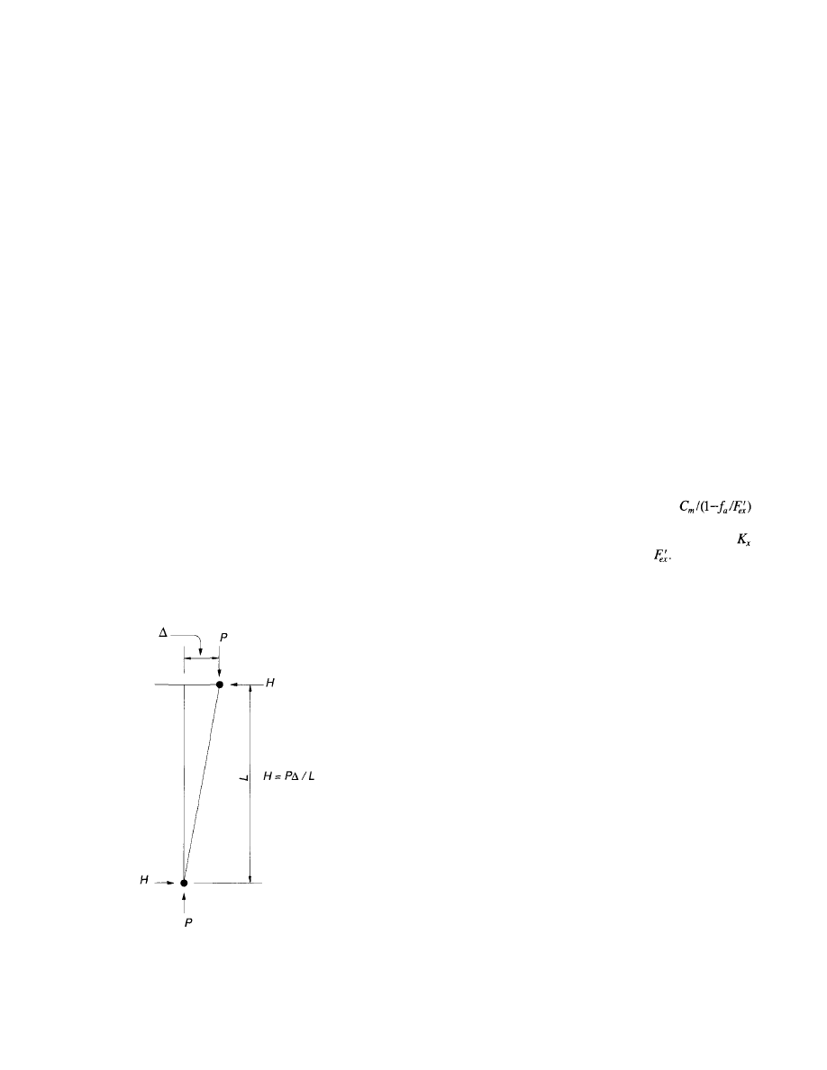
provides for frame stability by the use of a P-Delta moment
magnifier (factor B2 in Sect. H1.2.2 of the LRFD Specifi-
cation). Stabilizing forces must be provided for the columns
not participating in the moment resisting frames as shown
in Fig. 27. Normally, the forces can easily be transmitted
from the supported member to the supporting member by
diaphragm action through the floor slab. These columns
(nicknamed "leaner columns") are designed for the effec-
tive length factor K = 1.0. In the upper stories, columns
and/or girder sizes are likely to be those required for gravity
loading. The design procedure for the spandrel moment
resisting frames is shown in Appendix B. The computations
have been minimized to conserve space. Comments for each
sheet follow:
Sheet 1: Design load data and typical girder and filler beam
design using LRFD Manual.
Sheet 2: Gravity load girder moment design. Two cycle
moment distribution is for illustration only. Design pro-
cedure is optional.
Sheet 3 and Sheet 4: Column load tabulation for corner col-
umn and typical spandrel column.
Sheet 5: Service wind load calculation.
Fig. 27. Stability force for "leaner" column.
17
Sheet 6 and Sheet 7: Calculation of stiffnesses I/L required
to limit drift to target DI of 0.0025 and calculation of
moment magnifiers B2 at each column lift and each floor
level. Note that vertical load must be factored. The wind
load may or may not be factored so long as the accom-
panying DI has a matching load factor.
Sheet 8: Selection of column and girder sections to control
drift. The maximum column effective length factor K is
about 1.4.
Sheet 9: Wind frame elevation used with computer analysis
to compute wind moments and axial loads.
Sheet 10: Summary of frame deflections due to wind loads
and final girder design summary. Girder bottom flange
bracing requirements must also be checked.
Sheet 11: Final column design load summary.
Sheet 12 and Sheet 13: Final design of two columns, one
corner column, and one typical spandrel column.
A P-Delta procedure may be developed for use with the
ASD Specification. Section C2.2 of the Specification per-
mits the use of a rational method to determine the design
parameters. The design procedure for ASD will be similar
to that for LRFD with the following exceptions. First, the
design is made using service loads except that a load factor
of 1.3 should be applied to the sum of the vertical loads when
calculating the P-Delta moment magnifier. Both sway and
non-sway moments must be magnified by the
moment magnifier which occurs in the combined stress inter-
action Eq. 1.6-1a. And finally, the effective length factor
must be calculated in order to compute
Special Wind Frames
The introduction of powerful digital computers and power-
ful computer programs has revolutionized the design of lateral
load resisting systems. Now the widespread availability of
powerful microcomputers and frame analysis programs pro-
vides a means for the small consulting firm to use advanced
design concepts in moderate size projects. For example, the
structural consultant can now consider the use of facade brac-
ing, tubular design hat and/or belt trusses combined with
bracing frames and combinations of moment resisting and
bracing frames.
An understanding of the deflection characteristics of braced
and unbraced (moment resisting) frames is helpful in the
design of linked braced and unbraced frames as well as
braced frames that are combined with hat and belt trusses.
Figures 28a and 28b illustrate the overall deflection shapes
of a braced frame and moment resisting frame (member
curvature not shown). The braced frame deflects in the man-
ner of a cantilever beam—that is, the slope of the frame
increases with the height. For members participating in chord
action in braced frames, the wracking deflection to which
cladding is subjected is equal to the shear deflection due to
the strain in the bracing members. For members not par-
© 2003 by American Institute of Steel Construction, Inc. All rights reserved.
This publication or any part thereof must not be reproduced in any form without permission of the publisher.
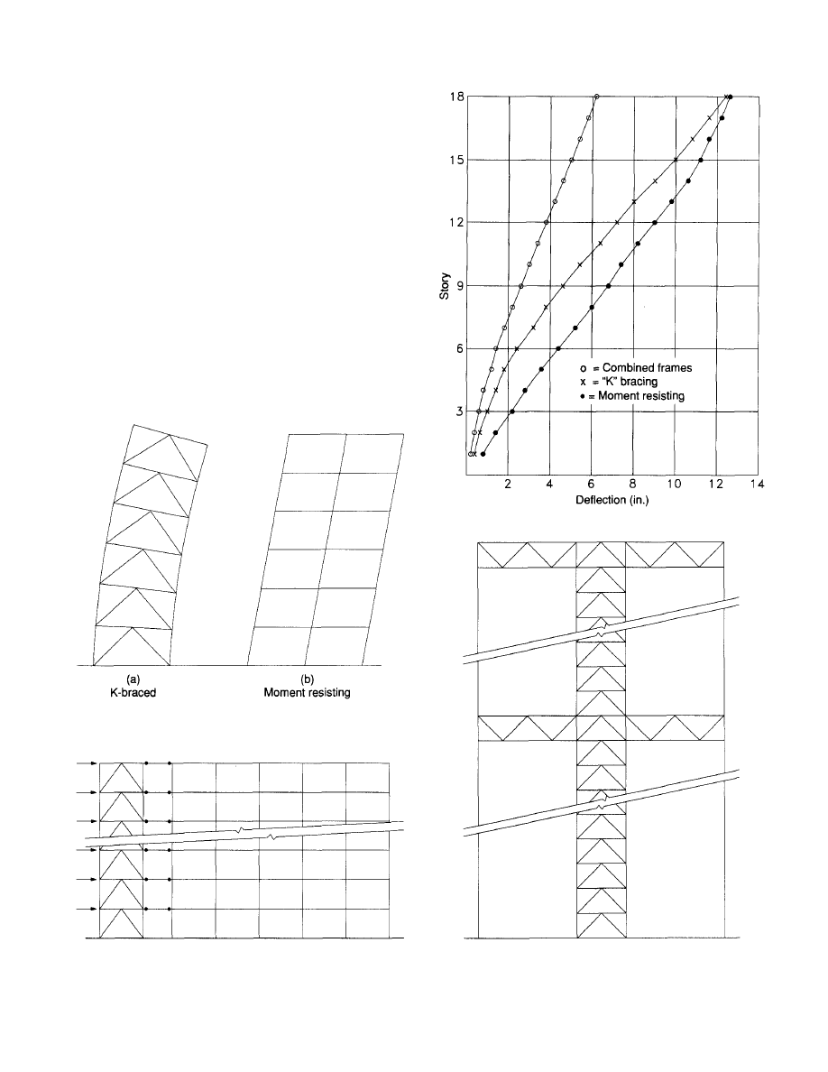
ticipating in chord action, such as spandrel members in core
braced buildings, the wracking deflection is equal to the total
story deflection. The story to story deflections also increase
appreciably with the height. On the other hand, for moment
resisting frames, the story deflections are more or less con-
stant from top to bottom, except at near the top the story
deflections tend to decrease. Combining the two systems
results in a very satisfactory solution. To illustrate the fact,
a combined frame was proportioned for an 18-story build-
ing with a plan similar to that shown in Fig. 25. In this exam-
ple, a spandrel moment resisting frame was linked with a
K-braced frame as shown in Fig. 29. Both the moment resist-
ing frame and K-braced frame were proportioned to resist
one-half of the wind load for a DI of 0.0025. Figure 30 shows
a plot of the moment resisting frame alone, the K-braced
frame alone, and the combined frame, all subjected to the
full wind load. The combined frame has a maximum deflec-
tion at the top of 6.25 in. (DI = 0.0023) for the full wind
load. The maximum deflection at the top for one-half wind
Fig. 28. Deflection characteristics.
Fig. 29. Linked frame computer model.
18
Fig. 30. Combined frame deflections.
Fig. 31. K-braced frame with hat and belt trusses.
© 2003 by American Institute of Steel Construction, Inc. All rights reserved.
This publication or any part thereof must not be reproduced in any form without permission of the publisher.
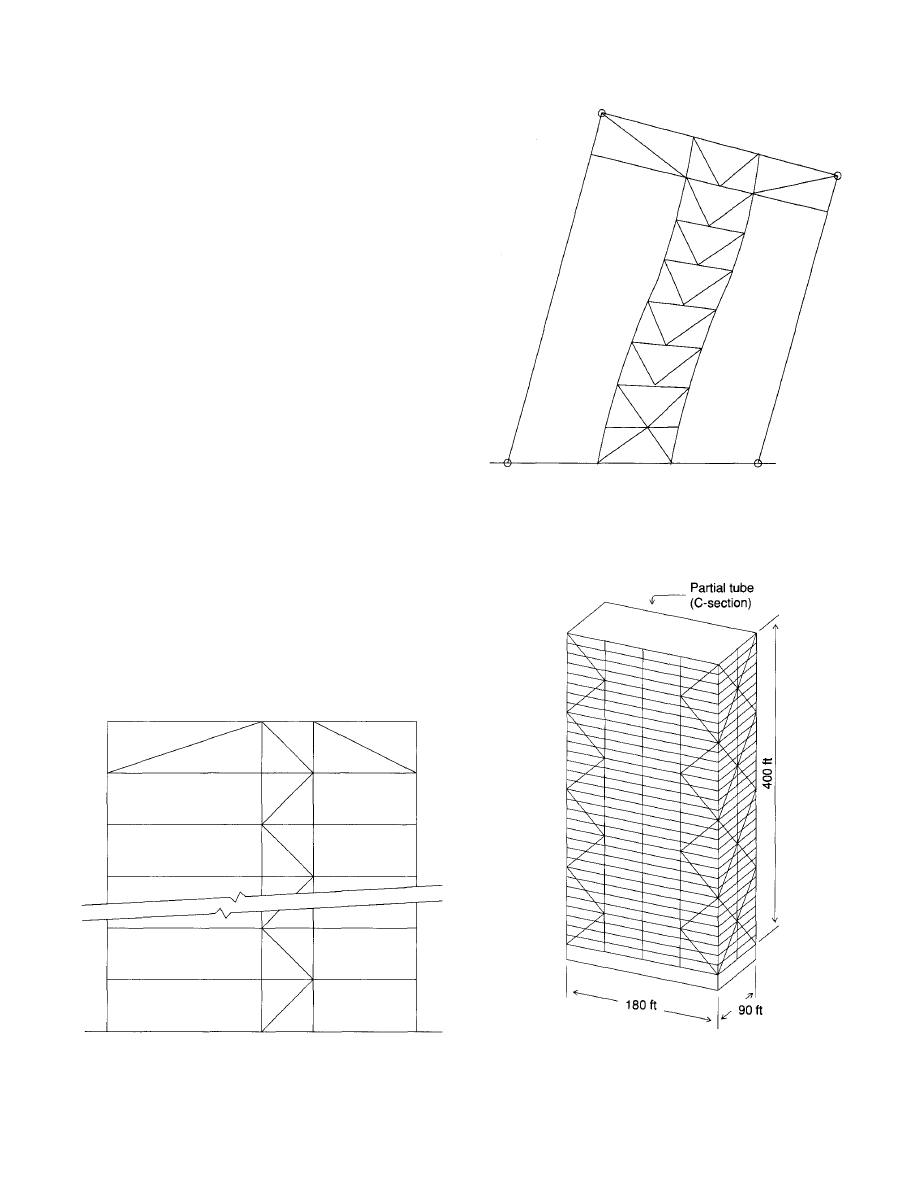
load would be 6.48 in. and 6.31 in. for the moment resisting
frame and the K-braced frame respectively. Thus the com-
bination frame has slightly less deflection than would be
expected (6.25 in. vs. 6.39 in.). The maximum story DIs are
0.0023, 0.00267, and 0.00314 respectively for the combined
frame with full wind load and the moment resisting and
braced frames with one-half of the wind load. The maxi-
mum girder moment in the moment resisting frame of 204
kip-ft at the second level for the one-half wind loading is
reduced to 158 kip-ft at the sixth level for the combined
frames. The maximum uplift in the braced bent of 661 kips
for the braced bent is increased to 734 kips for the combined
frames. As a result of the different deflected shapes, the K-
bracing takes a relatively larger proportion of the total story
wind shear near the bottom and proportionally less near the
top. In Fig. 30 the curve for the combined frames takes a
slight "S" shape.
The use of hat and/or belt trusses is a design method which
can significantly increase the efficiency of bracing frames
(Fig. 31). As an example, Fig. 32 illustrates a very slender
bracing frame with an aspect ratio of 12.4. With the introduc-
tion of the hat truss members at the elevator penthouse level,
the maximum deflection is reduced from 4.26 (DI = 0.0030)
to 2.66 (DI = 0.0019). The purpose of the hat and belt trusses
is to simply limit the rotation of the bracing bent as shown
in Fig. 33. Hat trusses can be very helpful in reducing deflec-
tion and high uplift forces in relatively low buildings (10 to
15 stories). Hat and belt trusses are effective in reducing the
rotation of a bracing bent as shown in Fig. 33. The design
of hat and belt trusses is described by McNabb and Muvdi
(1977) and Taranath (1974).
Facade bracing can be used to create a tubular structure
Fig. 32. Elevator core linked frame.
19
Fig. 33. Deflected shape bent with hat truss.
Fig. 34. Facade bracing.
© 2003 by American Institute of Steel Construction, Inc. All rights reserved.
This publication or any part thereof must not be reproduced in any form without permission of the publisher.
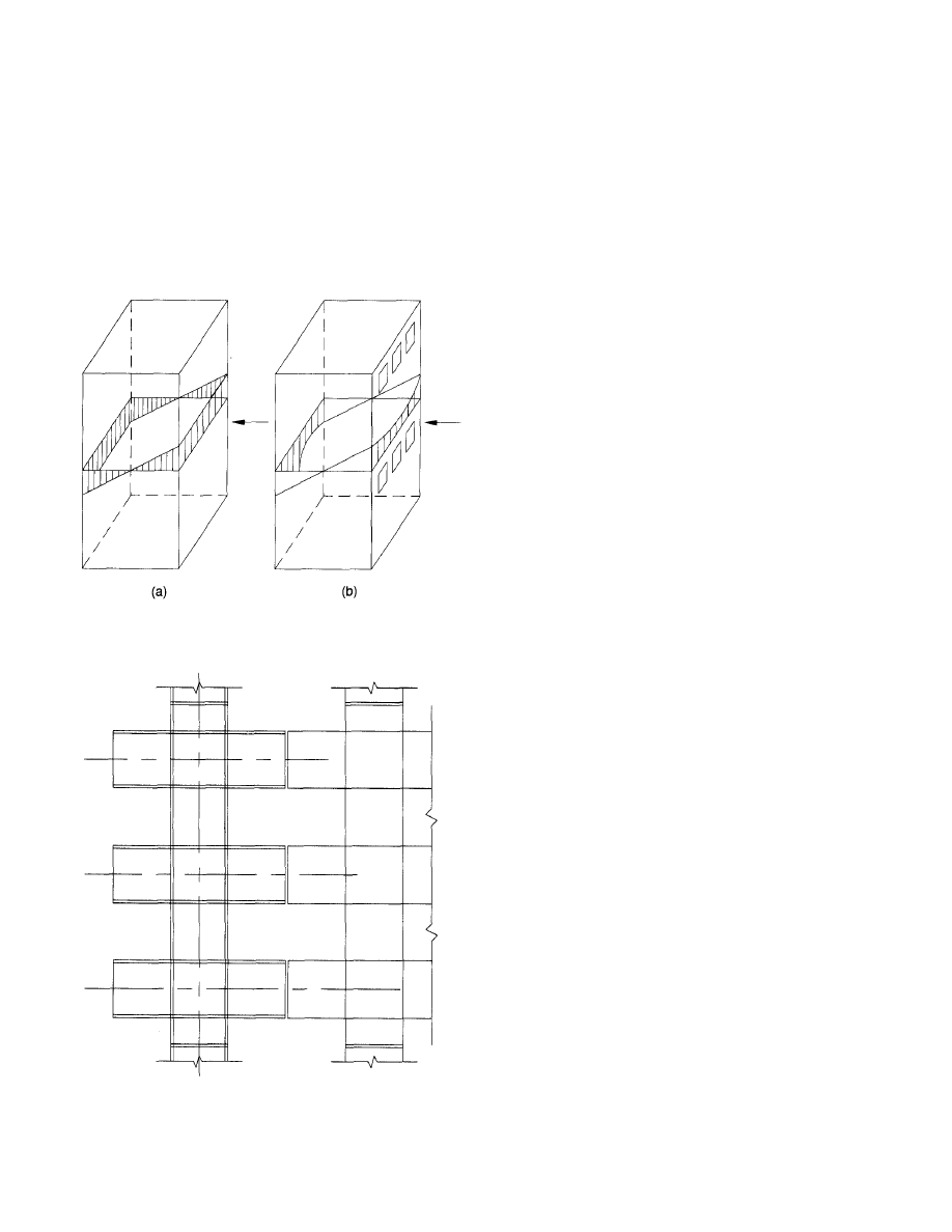
which can be an extremely efficient method of providing
lateral load resistance in a building frame. The premier exam-
ple may be the John Hancock Building located in Chicago,
Illinois. The design is essentially the same as that for a con-
ventional K-braced frame except that the effective depth of
the vertical truss element will be the width of the bracing
system. Colaco (1974) has described a method that uses
facade bracing to create partial tubular structures in mid-rise
buildings (Fig. 34).
Fig. 35. Tubular frame.
Fig. 36. Tree column.
The concept of tubular design is illustrated in Fig. 35a
and 35b. Figure 35a depicts the stress distribution that would
exist in a tube with solid walls. In a tubular building frame,
the walls are punctured with holes for windows. As a result
of the opening, shear lag associated with the bending in
beams and columns on the windward and leeward sides
reduces the efficiency of the tube (Fig. 35b). In tall build-
ings, often the exterior walls are framed with tree columns
(Fig. 36). Tree columns often consist of H-shaped columns
with H-shaped beam stubs fabricated from steel plates or
deep rolled wide flange shapes. Tree columns have shear con-
nections made midway between columns. Tube structures
are not likely to be economical for the design of buildings
less than 25 or 30 stories in height. Nair (1986) has described
a modified tube concept. The method seeks to concentrate
the column axial loads in the corners of the structure by creat-
ing a "soft sided tube."
REFERENCES
American Institute of Steel Construction (1978), Specifica-
tion/or the Design, Fabrication and Erection of Structural
Steel for Buildings, 1978, Chicago, IL.
American Institute of Steel Construction (1986), Load and
Resistance Factor Design Specification for Structural Steel
Buildings, 1986, Chicago, IL.
American Institute of Steel Construction (1986a), Manual
of Steel Construction, Load and Resistance Factor Design,
1986, Chicago, IL.
American Iron and Steel Institute and American Institute of
Steel Construction (1968), Plastic Design of Braced Mul-
tistory Steel Frames, AISC, 1968, Chicago, IL.
American National Standards Institute (1982), Minimum
Design Loads for Buildings and Other Structures, ANSI
A58.1-1982, 1982, New York.
American Society of Civil Engineers (1986), Ad Hoc Com-
mittee on Serviceability Research, "Structural Servicea-
bility: A Critical Appraisal and Research Needs," ASCE
Journal of the Structural Division, Vol. 112, No. 12,
December 1986, New York.
American Society of Civil Engineers (1988), Task Commit-
tee on Drift Control of Steel Building Structures of the
Committee on Design of Steel Building Structures, "Wind
Drift Design of Steel-framed Buildings: State-of-the-art
Report," Journal of the Structural Division, Vol. 114, No.
9, September 1988, New York (pp. 2085-2108).
Baker (1987), "Optimization of K-braced Frames," Private
Communication, 1987, Chicago, IL.
Building Officials and Code Administrators International
(1987), The BOCA Basic/National Building Code/1987,
1987, Country Club Hills, IL.
20
© 2003 by American Institute of Steel Construction, Inc. All rights reserved.
This publication or any part thereof must not be reproduced in any form without permission of the publisher.

Colaco, Joseph P. (1974), "Partial Tube Concept for Mid-
rise Structures," AISC Engineering Journal, 4th Qtr., 1974,
Chicago, IL (pp. 81-85).
Council on Tall Buildings and Urban Habitat (1979), Struc-
tural Design of Tall Buildings, ASCE, Vol. SB, 1979, New
York.
Galambos, Theodore V. (1988), "Vibration of Steel Joist Con-
crete Floors," Technical Digest, No. 5, Steel Joist Insti-
tute, 1988, Myrtle Beach, SC.
Galambos, Theodore V. and Bruce Ellingwood (1986),
"Serviceability Limit States: Deflection," ASCE Journal
of the Structural Division, Vol. 112, No. 1, January 1986,
New York (pp. 67-84).
McNabb, J. W. and B. B. Muvdi (1977), "Discussion: Drift
Reduction Factors for Belted High-rise Structures," AISC
Engineering Journal, 1st Qtr., 1977, Chicago, IL (pp.
44-47).
Murray, Thomas M. (1975), "Design to Prevent Floor Vibra-
tions," AISC Engineering Journal, 3rd Qtr., 1975, Chi-
cago, IL (pp. 82-87).
Murray, Thomas M. (1981), "Acceptability Criterion for
Occupant-induced Floor Vibrations," AISC Engineering
Journal, 2nd Qtr., 1981, Chicago, IL (pp. 62-70).
Murray, Thomas M. (1991), "Building Floor Vibrations,"
AISC Engineering Journal, 3rd Qtr., 1991, Chicago IL (pp.
102-109).
Murray, Thomas M. and William E. Hendrick (1977), "Floor
Vibrations and Cantilevered Construction," AISC Engi-
neering Journal, 3rd Qtr., 1977, Chicago, IL (pp. 85-91).
Nair, R. Shankair (1986), "A Modified Tube Concept for Tall
Buildings," AISC Engineering Journal, 3rd Qtr., 1986,
Chicago, IL (pp. 126-130).
Reed, Hansen and Van Marke (1972), "Human Response to
Tall Buildings Wind-induced Motion," ASCE-IABSE Inter-
national Preprints, Reports, Vol. 11-17, ASCE, August
1972, New York.
Rongoe, James (1984), "A Composite Girder System for Joist
Supported Slabs," AISC Engineering Journal, 3rd Qtr.,
1984, Chicago, IL (pp. 155-160).
Ruddy, John L. (1986), "Ponding of Concrete Deck Floors,"
AISC Engineering Journal, 3rd Qtr., 1986, Chicago, IL
(pp. 107-115).
Steel Joist Institute (1990), Standard Specifications, Load
Tables and Weight Tables for Steel Joists and Joist Girders,
1990, Myrtle Beach, SC.
Taranath, B. S. (1974), "Optimum Belt Truss Locations for
High-rise Structures," AISC Engineering Journal, 1st Qtr.,
1974, Chicago, IL (pp. 18-21).
Wiss, John
and Richard A. Parmelee (1974), "Human Per-
ception of Transient Vibrations," ASCE Journal of the
Structural Division, Vol. 100, No. ST4, New York (pp.
773-787).
21
© 2003 by American Institute of Steel Construction, Inc. All rights reserved.
This publication or any part thereof must not be reproduced in any form without permission of the publisher.
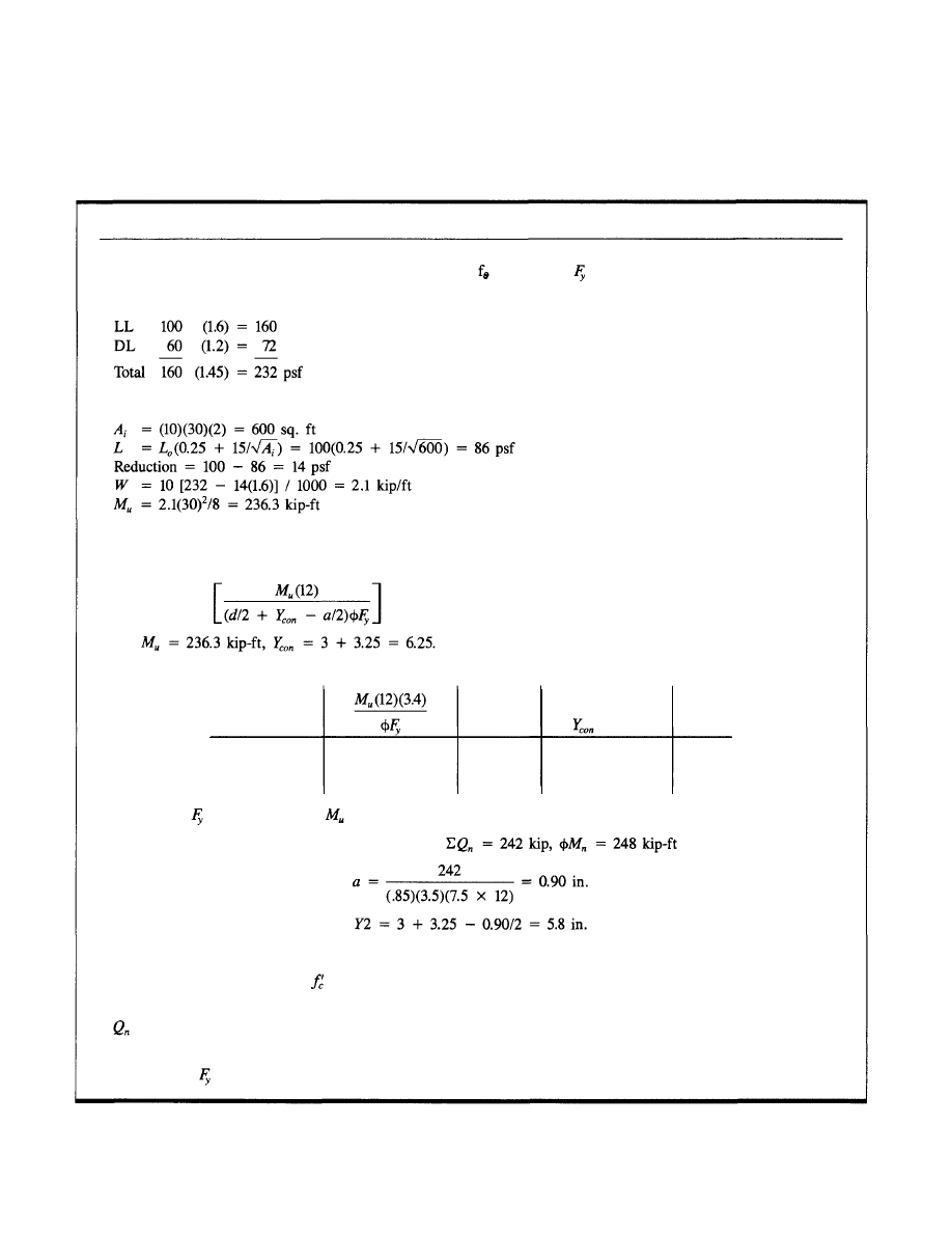
APPENDICES
23
LRFD COMPOSITE BEAM DESIGN
L = 30 ft Spacing = 10 ft b = (30/8)2 = 7.5 ft
= 3.5 ksi
= 36.0 ksi 3¼-in. slab + 3-in. deck
Loads
Live Load Reduction (1987 BOCA, sect. 1115)
(See AISC LRFD Manual for nomenclature.)
Preliminary Beam Section
Beam weight =
For Assume a = 1½ in.
Preliminary Beam Selections
Section
Nom. Depth
14
16
18
315.1
315.1
315.1
d/2
1
8
9
-
a/2
5.5
5.5
5.5
Wt.
25.2
23.3
21.7
Try W16x26,
= 36, Y2 = 5.5,
(Req'd) = 236.5
From pg. 4-23 LRFD Manual (see next page), for
Selection is satisfactory.
For ¾-in. dia. headed stud with
= 3.5 ksi
Conc. wt. = 115 pcf from LRFD Manual, pg. 4-7.
= 19.8 kips/stud
No. of studs req'd = (242/19.8)2 = 26
Use: W16x26, =
36
ksi, with twenty-six ¾-in. dia. headed studs.
© 2003 by American Institute of Steel Construction, Inc. All rights reserved.
This publication or any part thereof must not be reproduced in any form without permission of the publisher.
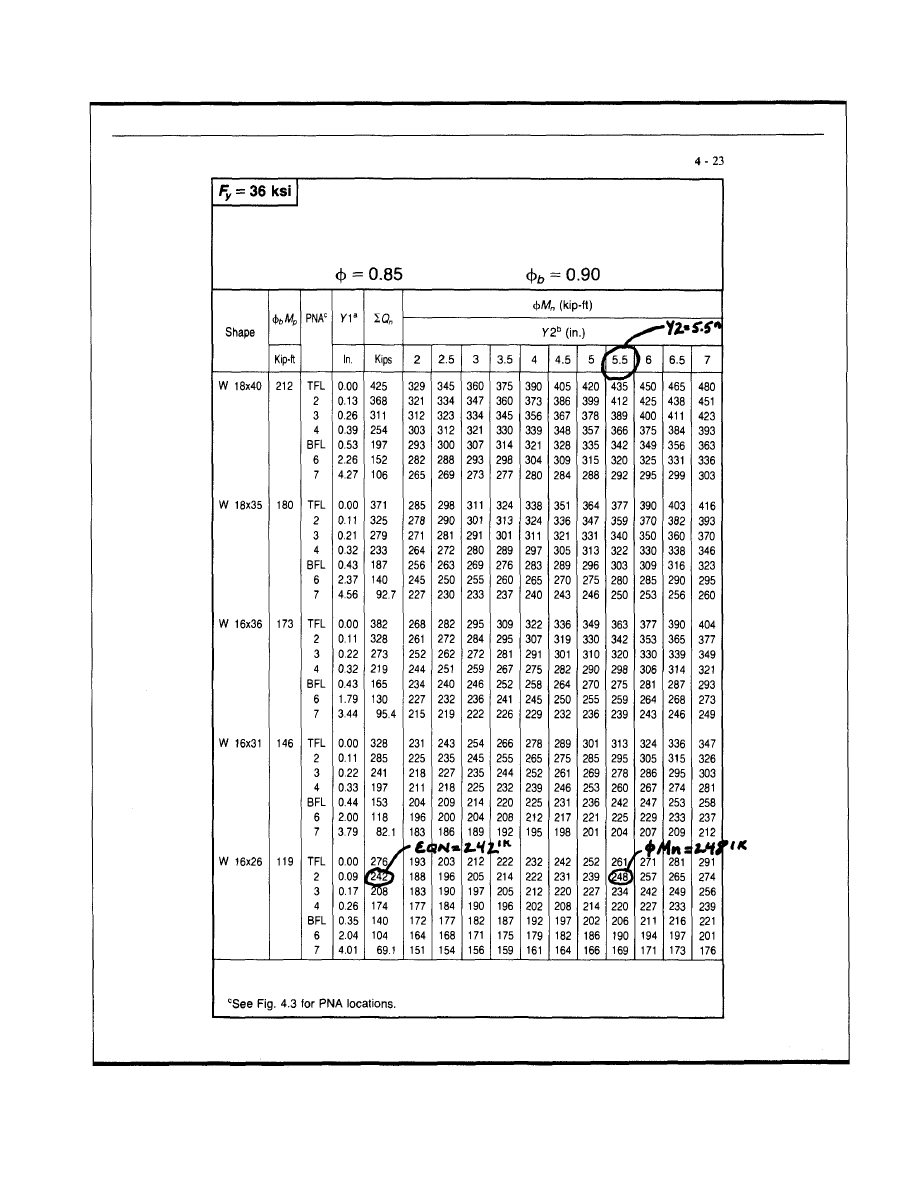
c
See Fig 4.3 for PNA locations
24
AMERICAN INSTITUTE OF STEEL CONSTRUCTION
COMPOSITE DESIGN
COMPOSITE BEAM SELECTION TABLE
W Shapes
LRFD COMPOSITE BEAM DESIGN (cont.)
a
Y1 = distance from top of the steel beam to plastic neutral axis.
b
Y2 = distance from top of the
l beam to concrete flange force.
.
stee
© 2003 by American Institute of Steel Construction, Inc. All rights reserved.
This publication or any part thereof must not be reproduced in any form without permission of the publisher.
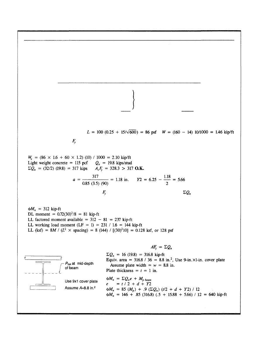
COMPOSITE BEAM LOAD CAPACITY ENHANCEMENT
Problem: Change occupancy from 100 psf LL office loading to 175 psf min. LL for automated filing system.
Original design—AISC Specifications for the Design, Fabrication and Erection of Structural Steel for Buildings,
Nov. 1, 1978, ASD.
Original Loads
LL
3¼-in. slab + 3-in. deck
Misc
Ceil.
Steel
ASD
100
46
4
5
5
160 psf
L.F.
(1.6)
(1.2)
(1.45)
LRFD
160
72
232 psf
ASD Design
L = 30 ft Spacing = 10 ft
Beam selection: W16x31,
= 36 ksi, with thirty-two ¾-in. dia. studs.
Check design using LRFD.
From pg. 4-23 LRFD Manual, for W16x31, =
36
ksi, with thirty-two ¾-in. dia. studs, =
317
by
interpolation.
From interpolation of Table in LRFD Manual page 4-23:
Upper Bound Moment Capacity of Section Controlled by Shear Stud Capacity
Note: To find upper-bound moment capacity, add a cover plate with
Use 9x1 cover plate
This value is too high for practical use. Connection and web shear design
will control.
25
© 2003 by American Institute of Steel Construction, Inc. All rights reserved.
This publication or any part thereof must not be reproduced in any form without permission of the publisher.
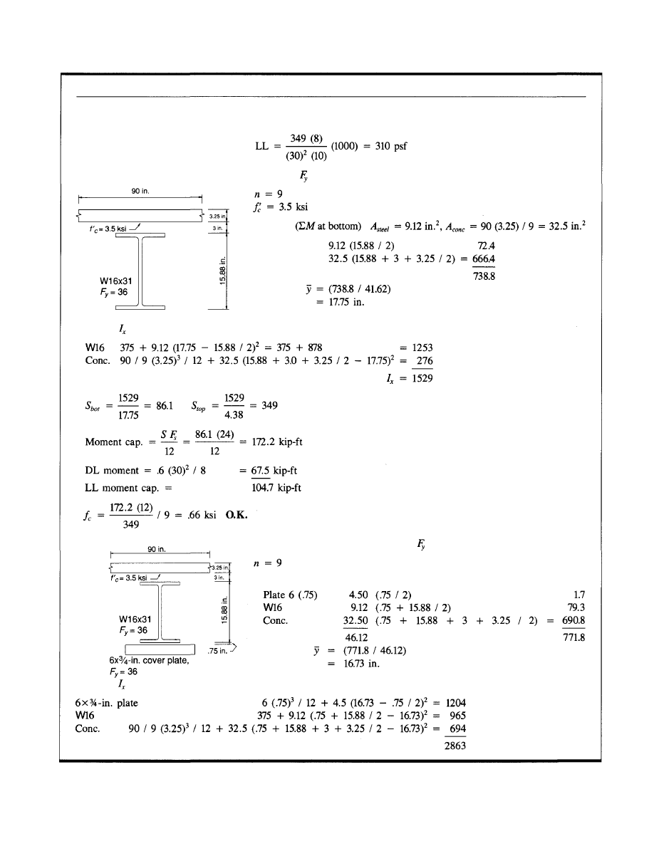
26
COMPOSITE BEAM LOAD CAPACITY ENHANCEMENT (cont.)
Live load moment capacity = (640 - 81) / 1.6 = 349
ASD Analysis
Find NA
Compute
ASD Analysis
Find NA
Compute
W16x31 =
36
ksi
W16x31 + 6 x ¾-in. cover plate =
36
ksi
© 2003 by American Institute of Steel Construction, Inc. All rights reserved.
This publication or any part thereof must not be reproduced in any form without permission of the publisher.
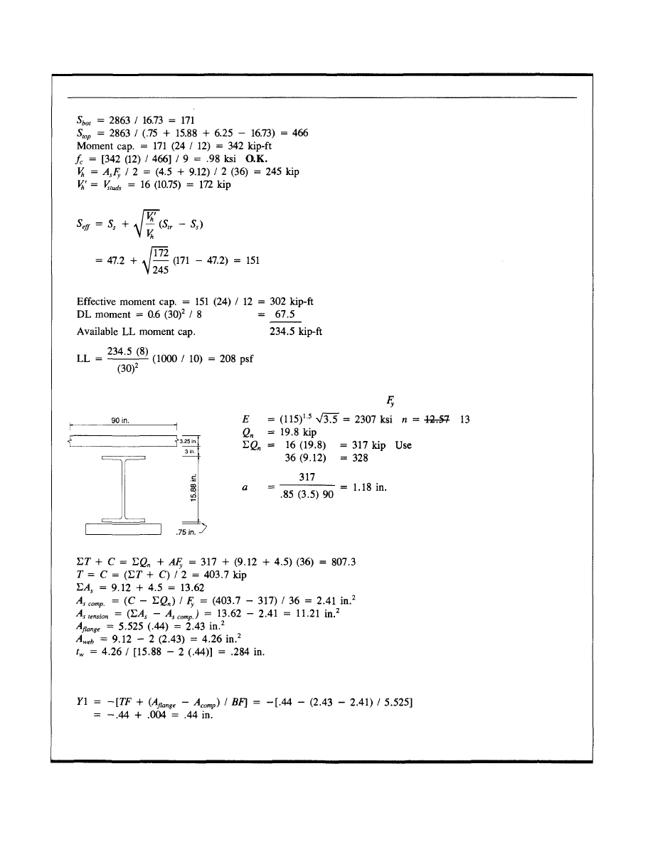
27
COMPOSITE BEAM LOAD CAPACITY ENHANCEMENT (cont.)
LRFD Analysis
Assume PNA is above bottom of top flange.
Take PNA at bottom of top flange.
W16x31 + 6 x ¾-in. cover plate =
36
ksi, with thirty-two ¾-in. dia. studs
© 2003 by American Institute of Steel Construction, Inc. All rights reserved.
This publication or any part thereof must not be reproduced in any form without permission of the publisher.
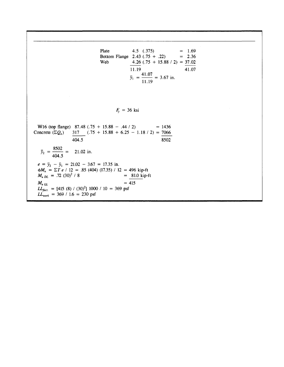
COMPOSITE BEAM LOAD CAPACITY ENHANCEMENT (cont.)
28
Find centroid of steel force:
Centroid of tension force is 3.67 above bottom of cover plate.
LRFD Analysis
W16x31 + 6-in x ¾-in. cover plate
Find centroid of compressive force (in terms of compressive force).
with thirty-two ¾-in. dia. studs
© 2003 by American Institute of Steel Construction, Inc. All rights reserved.
This publication or any part thereof must not be reproduced in any form without permission of the publisher.
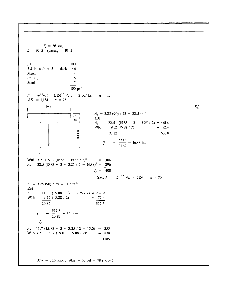
COMPOSITE BEAM LONG TERM DEFLECTION
29
Typical Filler Beam
W16x31
with thirty-two ¾-in. dia. studs
Find moment of inertia for short term loading (i.e., full value of
Compute
Find moment of inertia for long term loading
Compute
Deflection Summary
Assume 10 psf ambient LL for long term deflection
76 psf LL for short term deflection
Loads
© 2003 by American Institute of Steel Construction, Inc. All rights reserved.
This publication or any part thereof must not be reproduced in any form without permission of the publisher.
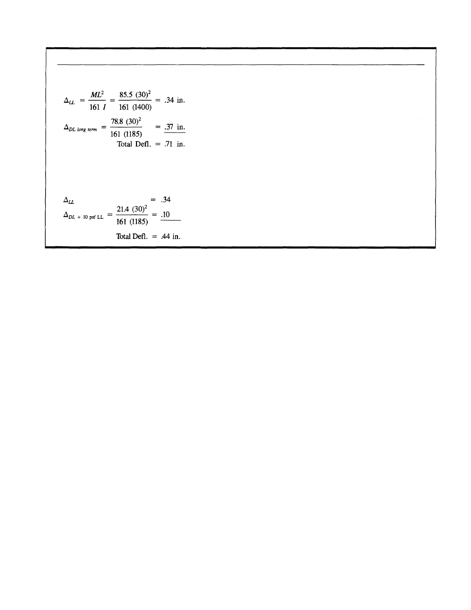
COMPOSITE BEAM LONG TERM DEFLECTION (cont.)
Shored Construction
Unshored Construction
(Assume camber overcomes dead load deflection.)
Long term load causing deflection 9 psf DL + 10 psf LL = 19 psf M = 21.4 kip-ft
30
© 2003 by American Institute of Steel Construction, Inc. All rights reserved.
This publication or any part thereof must not be reproduced in any form without permission of the publisher.
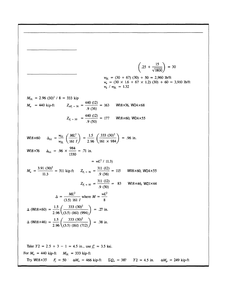
STEEL JOIST TYPICAL BAY
Joist L = 30 ft
Use 22K5 @ 3 ft
Girder
Reduced LL = 50
Simple Span
Use maximum beam depth = 18 in.
Composite Beam Design
Use LRFD Composite Beam Tables, pages 4-36 and 4-49.
31
LL
Part.
3-in. slab
Joist
Ceiling
Misc.
50 x 1.6 = 80
20
38
4 x 1.2 = 80
3
2
117 x 1.37 = 160
Continuous Design (assume max. moment
Conservatively take
Loads
© 2003 by American Institute of Steel Construction, Inc. All rights reserved.
This publication or any part thereof must not be reproduced in any form without permission of the publisher.
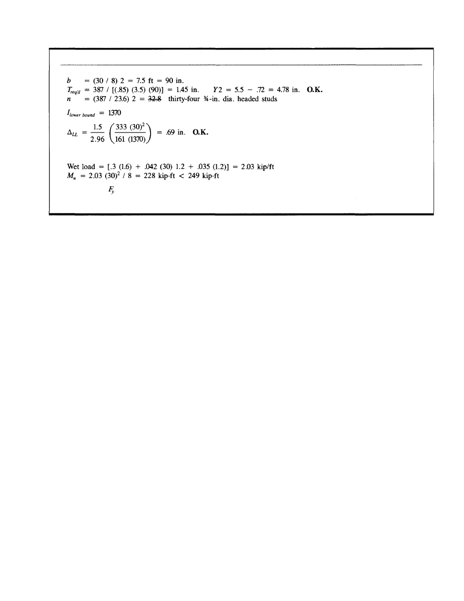
32
STEEL JOIST TYPICAL BAY (cont.)
Check wet load strength. Assume const. LL 0.3 kip/ft*
Use W18x35
= 50 ksi, thirty-four ¾-in. dia. studs.
* Some provision should be made for construction live load. In this case 9K per bay has been assumed.
© 2003 by American Institute of Steel Construction, Inc. All rights reserved.
This publication or any part thereof must not be reproduced in any form without permission of the publisher.
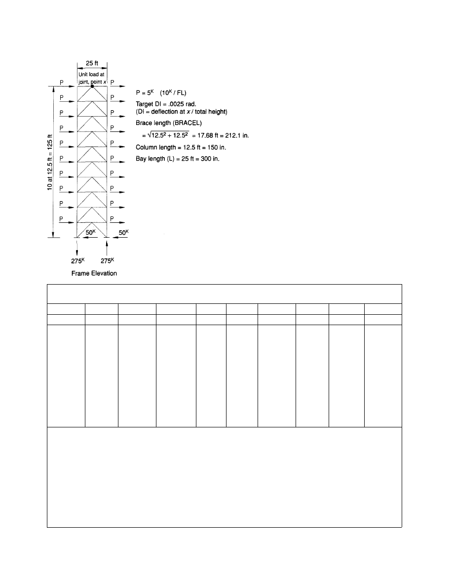
K-FRAME BRACING OPTIMIZATION
Table 1.
Member Loads
Col. No.
Item
FL(I)
10
9
8
7
6
5
4
3
2
1
1
WINDF
0
10
10
10
10
10
10
10
10
10
10
2
STYSHR
0
10
20
30
40
50
60
70
80
90
100
3
STYMOM
0
125
250
375
500
625
750
875
1,000
1,125
1,250
4
COLP
0
5
15
30
50
75
105
140
180
225
5
GIRDP
5
10
15
20
25
30
35
40
45
50
6
BRACEP
7.07
14.14
21.21
28.28
35.36
42.43
49.50
56.57
63.64
70.71
7
COLP1
0
.5
1.0
1.5
2.0
2.5
3.0
3.5
4.0
4.5
8
GIRDP1
0
.5
.5
.5
.5
.5
.5
.5
.5
.5
9
BRACP1
.707
.707
.707
.707
.707
.707
.707
.707
.707
.707
1 — WINDF: Story wind force (kip)
2 — STYSHR: Story wind shear = WINDF (I) + STYSHR (I + 1)
3 — STYMOM: Story moment = STYSHR (I) x HT (I)
4 — COLP: Col. axial load = COLP (I + 1) + STYMOM (I + 1) / L
5 — GIRDP: Girder axial load = STYSHR (I) / 2
6 — BRACEP: Brace axial load = STYSHR (I) / 2 x [brace L / (L / 2)]
7 — COLP1: Col. virtual load = COLP (I + 1) + (1) x HT (I + 1) / L
8 — GIRDP1: Girder virtual load = ½ = .5
9 — BRACP1: Brace virtual load = .5 x [brace L / (L / 2)] = .707
HT (I)
= Story height
L =
Bay
length
(c.t.c. columns)
brace L = Brace length
33
© 2003 by American Institute of Steel Construction, Inc. All rights reserved.
This publication or any part thereof must not be reproduced in any form without permission of the publisher.
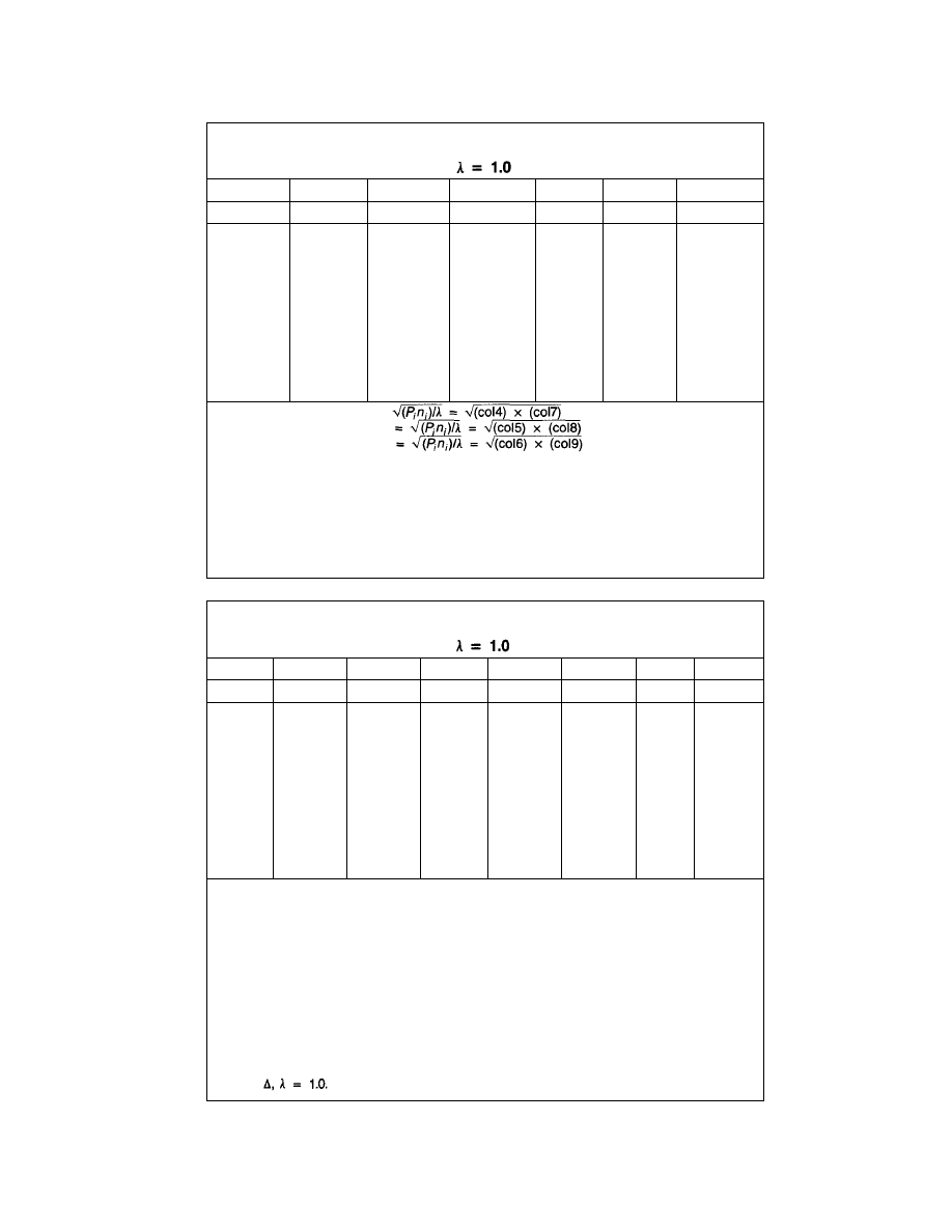
K-FRAME BRACING OPTIMIZATION (cont.)
Table 2.
Member Areas and Strains
Col. No.
Item
FL (I)
10
9
8
7
6
5
4
3
2
1
10
COLAR
0.0
1.58
3.87
6.71
10.0
13.69
17.75
22.14
26.83
31.82
11
GIRDAR
0.0
2.24
2.74
3.16
3.54
3.87
4.18
4.47
4.74
5.00
12
BRACAR
2.24
3.16
3.87
4.47
5.00
5.48
5.92
6.32
6.71
7.07
13
COLD
0.0
.0164
.0200
.0213
.0259
.0283
.0306
.0327
.0347
.0366
14
GIRDD
.0231
.0327
.0401
.0463
.0572
.0567
.0612
.0654
.0694
.0732
15
BRACED
0.0
.0231
.0283
.0327
.0366
.0401
.0433
.0463
.0491
.0572
10 — COLAR: Col. area =
11 — GIRDAR: Girder area
12 — BRACAR: Brace area
13 — COLD: Column strain = [COLP x HT (I)] / (COLAR x E)
= [(col4) x HT (I)] / [(col10) x E]
14 — GIRDD: Girder strain = (GIRP x L / 2) / (GIRDAR x E)
= [(col5) x L / 2] / [(col11) x E]
15 — BRACED: Brace strain = (BRACEP x BRACEL) / (BRACAR x E)
= [(col6) x BRACEL] / [(col12) x E]
E = Young's modulus = 29.0 ksi.
Table 3.
RHOs and Deflections
Col. No.
Item
FL (I)
10
9
8
7
6
5
4
3
2
1
16
COLRHO
0.0
.00011
.00014
.00015
.00017
.00019
.00021
.00022
.00023
.00024
17
SUMROC
.00166
.00155
.00141
.00126
.00109
.00090
.00069
.00047
.00024
0.0
18
GIRRHO
0.0
.00015
.00019
.00022
.00024
.00027
.00029
.00031
.00033
.00034
19
BRARHO
.00022
.00031
.00038
.00044
.00049
.00053
.00058
.00062
.00065
.00069
20
SUMRHO
.00188
.00201
.00198
.00192
.00182
.00170
.00156
.00140
.00122
.00103
21
FLDEL
.282
.302
.297
.288
.273
.255
.234
.210
.183
.155
22
TOTDEL
2.479*
2.197
1.895
1.598
1.310
1.037
.782
.548
.338
.155
16 — COLRHO: Col. floor RHO = 2 x COLD / L = 2 x (col13) / L
17 — SUMROC: Sum of col. RHO — 1st story: SUMROC = (col17) = 0
Above: SUMROC (I) = SUMROC (I - 1) + COLRHO (I)
= (col17) + (col16)
18 — GIRRHO: Girder fl. RHO = GIRDD / HT = (col14) / HT
19 — BRARHO: Brace fl. RHO = BRACED x (2 x brace L) / (L x HT)
= (col15) x (2 x brace L) / (L x HT)
20 — SUMRHO: Sum of RHOs @ FL = SUMROC + GIRRHO + BRARHO
= (col17) + (col18) + (col19)
21 — FLDEL: Floor deflection = SUMRHO x HT = (col20) x HT
22 — TOTDEL: Total floor deflection = FLDEL (I) + TOTDEL (I - 1)
= col21 (I) + col22 (I - 1)
* Max
34
© 2003 by American Institute of Steel Construction, Inc. All rights reserved.
This publication or any part thereof must not be reproduced in any form without permission of the publisher.
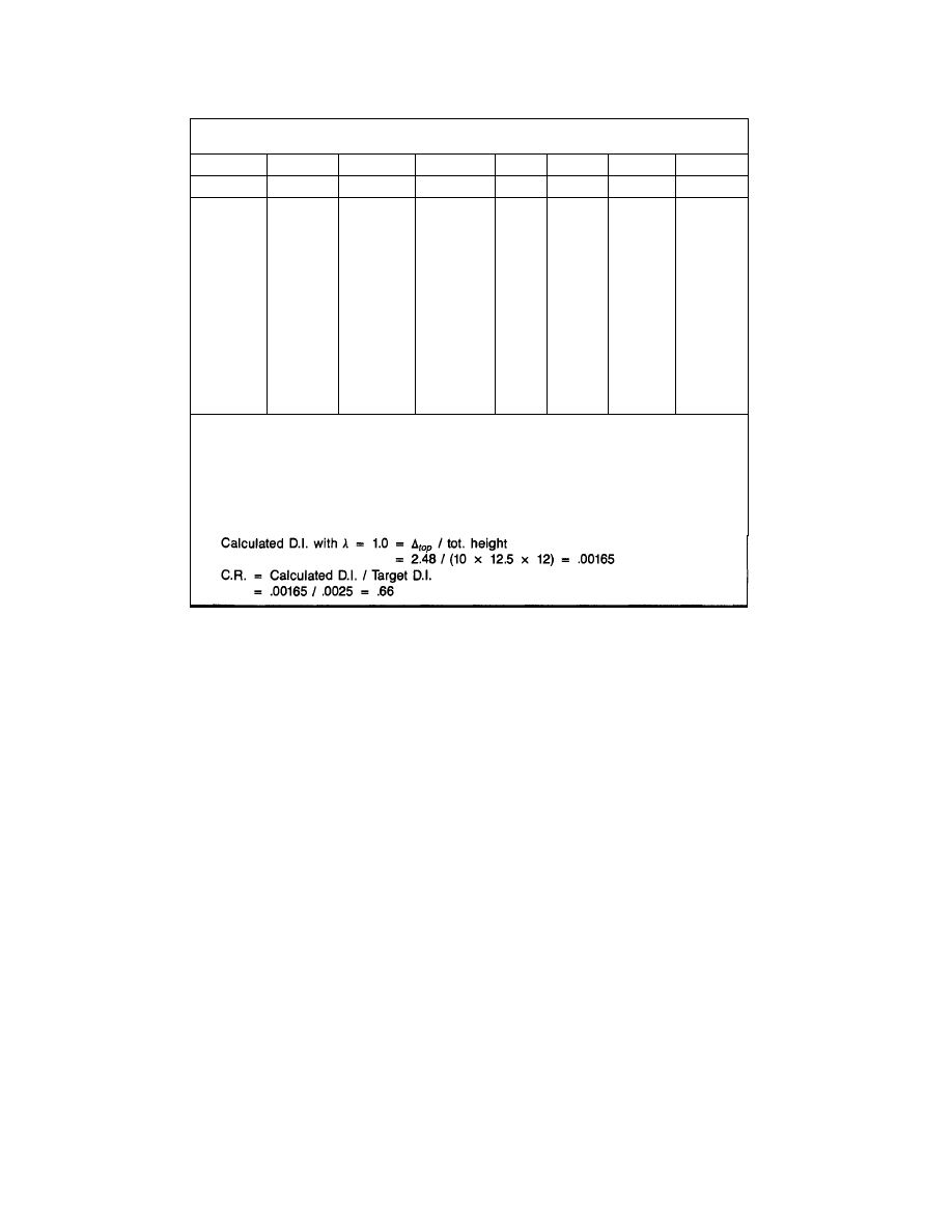
K-FRAME BRACING OPTIMIZATION (cont.)
Table 4.
Optimum Areas
Col. No.
Item
FL (I)
10
9
8
7
6
5
4
3
2
1
23
COLAR
0.0
1.58
3.87
6.71
10.0
13.69
17.75
22.14
26.83
31.82
24
GIRDAR
0.0
2.24
2.74
3.16
3.54
3.87
4.18
4.47
4.74
5.00
25
BRACAR
2.24
3.16
3.87
4.47
5.00
5.48
5.92
6.32
6.71
7.07
26
C.R.
.6
—
—
—
—
—
—
—
—
.66
27
ACOL
0.0
1.04
2.55
4.43
6.60
9.04
11.72
14.61
17.71
21.00
28
AGIRD
0.0
1.48
1.81
2.09
2.34
2.55
2.76
2.95
3.13
3.30
29
ABRAC
1.48
2.09
2.55
2.95
3.30
3.62
3.91
4.17
4.43
4.67
23, 24, 25 — Repeat of columns 10, 11, 12
26 — Correction factor
27 — ACOL: Optimum column area = (col23) x (col26)
28 — AGIRD: Optimum girder area = (col24) x (col26)
29 — ABRAC: Optimum brace area = (col25) x (col26)
Correction factor (CR)
Target D.I. = 0.0025 radians
35
© 2003 by American Institute of Steel Construction, Inc. All rights reserved.
This publication or any part thereof must not be reproduced in any form without permission of the publisher.
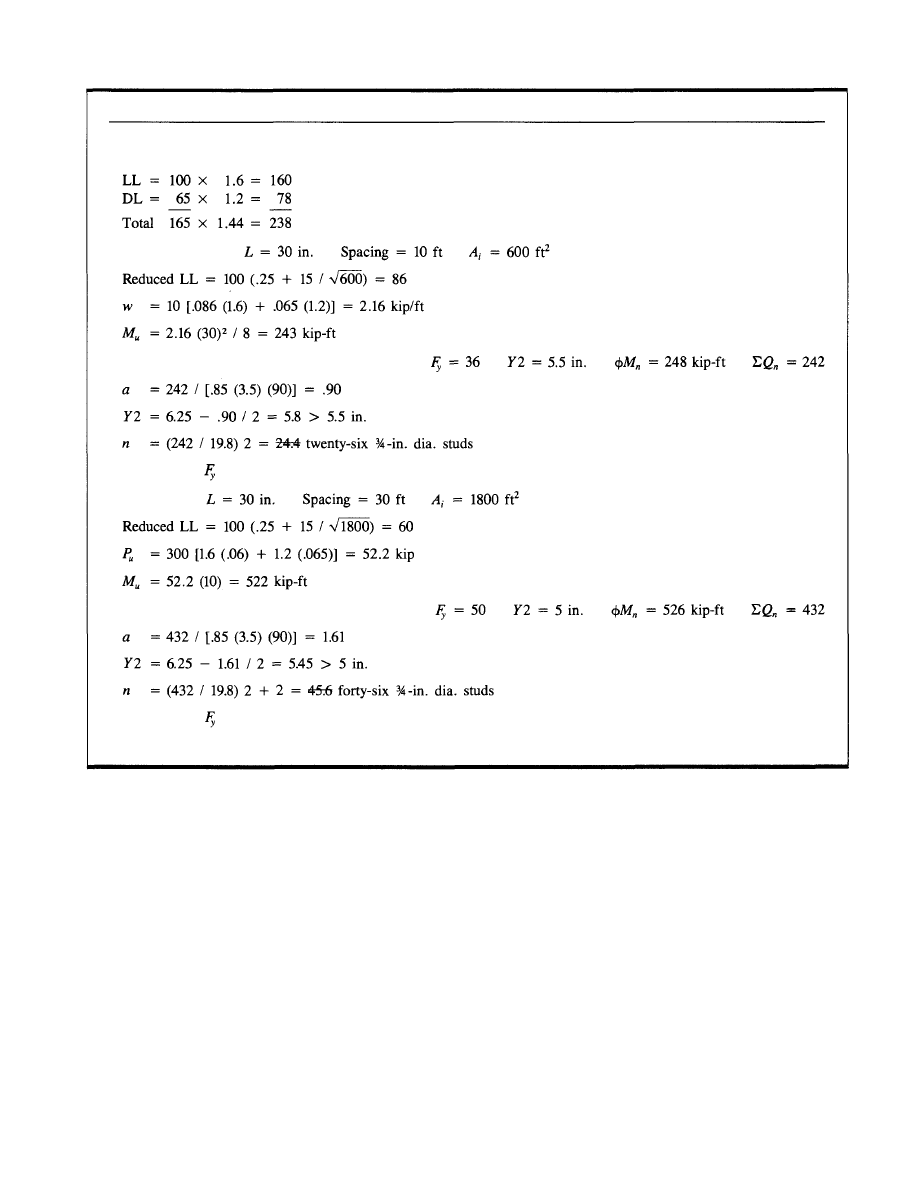
UNBRACED FRAME DESIGN
36
Loads
Typical filler beam:*
From the LRFD Manual (pg. 4-23) try W16x26
Use W16x26
= 36 with twenty-six ¾-in. dia. studs.
Typical girder:
From the LRFD Manual (pg. 4-36) try W18x40
Use W18x40
= 50 ksi with forty-six ¾-in. dia. studs.
* Note: Wet load strength and deflection calculations omitted for brevity.
© 2003 by American Institute of Steel Construction, Inc. All rights reserved.
This publication or any part thereof must not be reproduced in any form without permission of the publisher.
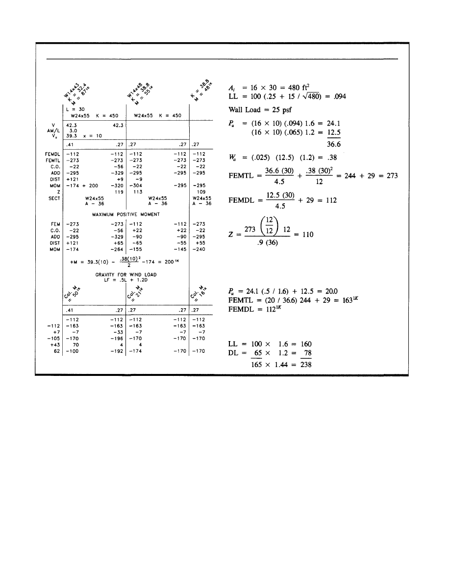
UNBRACED FRAME DESIGN (cont.)
37
Spandrel Beam Loads
For Wind-Gravity Loading
Design Loads
Gravity Girder Moment for Wind Load
Try W24x55 A36
© 2003 by American Institute of Steel Construction, Inc. All rights reserved.
This publication or any part thereof must not be reproduced in any form without permission of the publisher.

UNBRACED FRAME DESIGN (cont.)
Number of Stories
9
1
Total = 10 Stories
Number of Stories
10
Number of Stories
10
TL (psf)
165.0
60.0
Bay: Length (ft)
16.00
Added DL (kips)
9.00
LL (psf)
100.0
30.0
Width (ft)
16.00
Type of LL Reduction: 1984 BOCA Code
Corner Column*
Floor
Roof
9
8
7
6
5
4
3
2
1
Load
24
51
51
51
51
51
51
51
51
51
Red
0
7
14
15
16
16
17
17
17
17
Tot
P
24
68
105
141
176
211
246
280
314
348
DL/TL
.70
.62
.65
.67
.68
.69
.69
.70
.71
.71
Fact P
1.6L + 1.2D
31
92
141
188
234
279
325
370
413
459
0.5L + 1.2D
24
64
100
136
172
207
242
211
312
347
* Loads shown in kips
38
Typical Corner
Working from bottom to top:
© 2003 by American Institute of Steel Construction, Inc. All rights reserved.
This publication or any part thereof must not be reproduced in any form without permission of the publisher.
UNBRACED FRAME DESIGN (cont.)
Typical Spandrel
Working from bottom to top:
Number of Stories
9
1
Total = 10 Stories
Number of Stories
10
Number of Stories
10
TL (psf)
165.0
60.0
Bay: Length (ft)
16.00
Added DL (kips)
9.00
LL (psf)
100.0
30.0
Width (ft)
30.00
Type of LL Reduction: 1984 BOCA Code
Typical Spandrel Column*
Floor
Roof
9
8
7
6
5
4
3
2
1
Load
38
88
88
88
88
88
88
88
88
88
Red
0
20
29
31
32
32
30
29
29
29
Tot
P
37
106
165
222
279
335
394
453
512
572
DL/TL
.63
.60
.63
.65
.66
.67
.67
.67
.67
.67
Fact P
1.6L + 1.2D
50
144
222
298
373
447
524
603
681
761
0.5L + 1.2D
35
97
155
212
269
325
382
440
498
556
* Loads shown in kips
39
© 2003 by American Institute of Steel Construction, Inc. All rights reserved.
This publication or any part thereof must not be reproduced in any form without permission of the publisher.

UNBRACED FRAME DESIGN (cont.)
Basic Wind Speed: 70
Wind Distribution Coefficients
Windward .8
Bent: Spandrel Wind Frame
Parapet: Ht
Width
Area
3.13 76.00 238
Number of Stories: 10
No. of Stories
Story Ht
10
Parapet H = 5.2 kips
Exposure: B
Leeward .5
Penthouse: Ht
Width
.00 .00
Panel Width
Area
76.00 950
Penthouse H = 0 kips
Area
0
Floor
Roof
10
9
8
7
6
5
4
3
2
Floor H
19.9
18.5
18.5
18.5
17.0
14.8
14.8
14.0
12.6
12.3
Sum H
19.9
38.5
57.0
75.5
92.5
107.3
122.1
136.1
148.8
161.1
Vel Press
17
15
15
15
15
12
12
11
10
10
H Top
9.5
9.3
9.3
9.3
7.7
7.4
7.4
6.7
6.2
6.2
H Bot
9.3
9.3
9.3
9.3
7.4
7.4
7.3
6.5
6.2
6.2
Fl Elev
125.00
112.50
100.00
87.50
75.00
62.50
50.00
37.50
25.00
12.50
Total Wind Shear = 167.3
40
12.50
© 2003 by American Institute of Steel Construction, Inc. All rights reserved.
This publication or any part thereof must not be reproduced in any form without permission of the publisher.
UNBRACED FRAME DESIGN (cont.)
Stiffness values (I/L) output are to be multiplied by beam or column length (ft) in order
to get the required member moment of inertia (in.
4
).
Point of contraflexure is assumed to be at mid-height of all columns
E = 29,000 ksi
Number of Stories: 10
Number of Rows of Columns: 6
Story DI (Deflection/Story Ht.) = .0025
Floor
10
9
8
7
6
5
4
3
2
1
Story Ht
12.50
12.50
12.50
12.50
12.50
12.50
12.50
12.50
12.50
12.50
Wind Load
19.90
18.50
18.50
18.50
17.00
14.80
14.80
14.00
12.60
12.30
Sum of
Wind Load
19.90
38.40
56.90
75.40
92.40
107.20
122.00
136.00
148.60
160.90
Vert Load
1639
1350
1235
1293
1293
1293
1293
1293
1293
1293
Sum of
Vert Load
1639
2989
4224
5517
6810
8103
9396
10689
11982
13275
41
© 2003 by American Institute of Steel Construction, Inc. All rights reserved.
This publication or any part thereof must not be reproduced in any form without permission of the publisher.

UNBRACED FRAME DESIGN (cont.)
Floor
10
9
8
7
6
5
4
3
2
1
Factor
3.43
6.62
9.81
13.00
15.93
18.48
21.03
23.45
25.62
27.74
Stiffness (I/L)
16.47
32.94
24.12
31.78
39.43
47.09
54.74
62.40
69.43
76.47
82.59
88.72
94.84
100.97
106.76
112.55
117.77
122.98
128.07
133.16
Moment Magnifier
1.259
1.259
1.250
1.242
1.235
1.228
1.226
1.224
1.225
1.226
1.229
1.233
1.236
1.238
1.241
1.245
1.249
1.252
1.256
1.260
42
© 2003 by American Institute of Steel Construction, Inc. All rights reserved.
This publication or any part thereof must not be reproduced in any form without permission of the publisher.

UNBRACED FRAME DESIGN (cont.)
Column Trial Sections
43
Floor
Roof
9
8
7
6
5
4
3
2
1
Stiff.
32.94
31.78
47.09
62.40
76.47
88.72
100.97
112.55
122.98
133.16
Avg.
37.27
75.86
106.8
128.1
Typ. Col.
466
948
1335
1601
Sect.
14x48
14x90
14x120
14x145
Corner Col.
280
569
801
961
Sect.
14x43
14x61
14x74
14x90
Stiff.
16.47
24.12
39.43
54.74
69.43
82.59
94.84
106.76
117.77
128.07
Girder
494
724
1180
1642
2083
2478
2935
3203
3533
3842
Sect.
—
24x55
24x55
24x76
24x76
24x76
27x94
27x94
27x94
30x99
I
I
I
© 2003 by American Institute of Steel Construction, Inc. All rights reserved.
This publication or any part thereof must not be reproduced in any form without permission of the publisher.
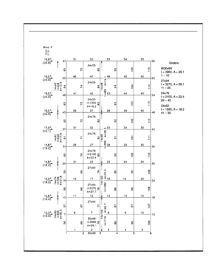
UNBRACED FRAME DESIGN (cont.)
44
Wind Frame Elevation
© 2003 by American Institute of Steel Construction, Inc. All rights reserved.
This publication or any part thereof must not be reproduced in any form without permission of the publisher.
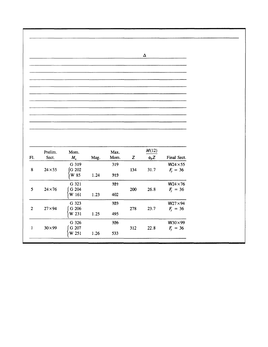
UNBRACED FRAME DESIGN (cont.)
Service Wind Load Deflections
10
9
8
7
6
5
4
3
2
1
61
55
49
43
37
31
25
19
13
7
125.0
112.5
100.0
87.5
75.0
62.5
50.0
37.5
25.0
12.5
3.63
3.19
2.89
2.52
2.20
1.81
1.41
1.06
0.68
0.32
0.0024
0.0024
0.0024
0.0024
0.0024
0.0024
0.0024
0.0024
0.0023
0.0021
Final Girder Design
45
Floor Joint
No. Elev. DI
© 2003 by American Institute of Steel Construction, Inc. All rights reserved.
This publication or any part thereof must not be reproduced in any form without permission of the publisher.
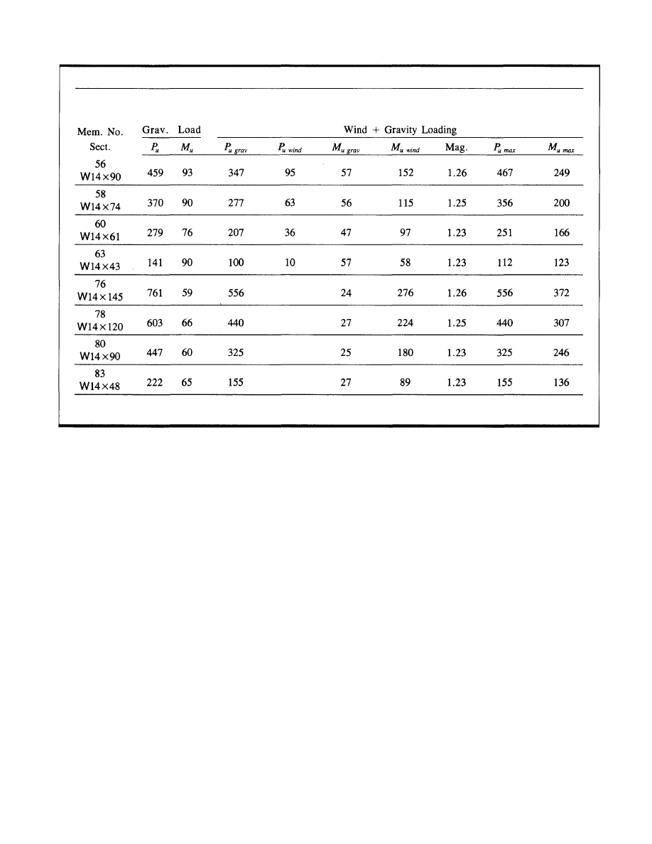
UNBRACED FRAME DESIGN (cont.)
Note: The first four columns (from the top) are corner columns and axial loads are increased under the influence of wind.
46
Final Design Column Loads
© 2003 by American Institute of Steel Construction, Inc. All rights reserved.
This publication or any part thereof must not be reproduced in any form without permission of the publisher.
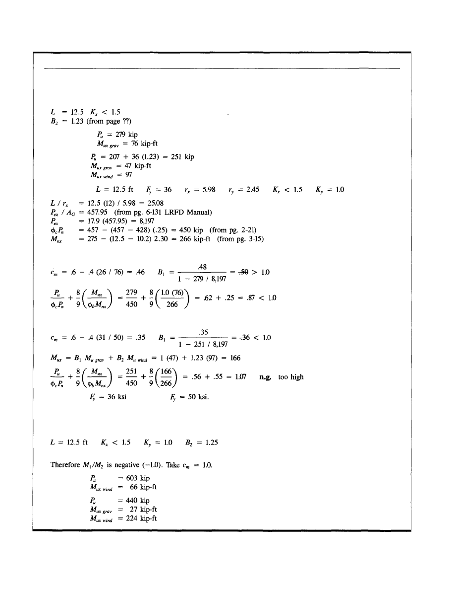
UNBRACED FRAME DESIGN (cont.)
47
Final Column Design
Corner Column — 3rd Lift
Gravity loads:
Wind loads:
Try W14x61
For gravity load
For wind load
Use W14x74
or W14x61
Final Column Design
Spandrel Column — 1st Lift
Under the influence of gravity load column can experience single curvature bending.
Gravity loads:
Wind loads:
© 2003 by American Institute of Steel Construction, Inc. All rights reserved.
This publication or any part thereof must not be reproduced in any form without permission of the publisher.
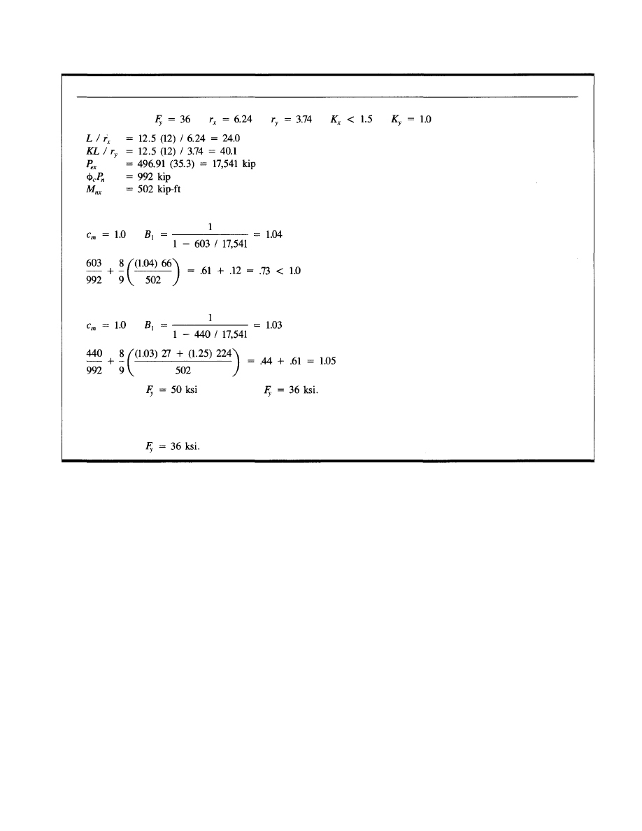
UNBRACED FRAME DESIGN (cont.)
48
Try W14x120
For gravity load
For wind load
Try W14x120
or W14x132
Note: If a W14x132 column is selected, the drift will be reduced. The mill material costs are close; 120 (.28) =
$33.60 / ft vs. 132 (.25) = $33.00 / ft.
Try W14x132
© 2003 by American Institute of Steel Construction, Inc. All rights reserved.
This publication or any part thereof must not be reproduced in any form without permission of the publisher.

DESIGN GUIDE SERIES
American Institute of Steel Construction, Inc.
One East Wacker Drive, Suite 3100
Chicago, Illinois 60601-2001
Pub. No. D 8 0 5 (3M793)
© 2003 by American Institute of Steel Construction, Inc. All rights reserved.
This publication or any part thereof must not be reproduced in any form without permission of the publisher.
Wyszukiwarka
Podobne podstrony:
Fred Saberhagen The Book of the Gods 05 Gods of Fire and Thunder
Fred Saberhagen Book of the Gods 05 Gods of Fire and Thunder
Mussolini's Seizure of Power and the Rise of?scism in Ital
Design Guide 02 Design of Steel and Composite Beams with Web Openings
Design Guide 10 Erection Bracing of Low Rise Structural Steel Frames
02 Modeling and Design of a Micromechanical Phase Shifting Gate Optical ModulatorW42 03
Design Guide 12 Modification of Existing Steel Welded Moment Frame
Eurocode 6 Part 2 1996 2006 Design of Masonry Structures Design Considerations, Selection of Mat
Eurocode 8 Part 1 1998 2004 Design of Structures for Earthquake Resistance General Rules Seism
Eurocode 2 Part 3 2006 UK NA Design of concrete structures Liquid retaining and containing struc
Eurocode 8 Part 5 1998 2004 Design of Structures for Earthquake Resistance Foundations, Retaini
Eurocode 8 Part 4 1998 2006 Design of tructures for Earthquake Resistance Silos, Tanks and Pipe
Eurocode 8 Part 6 1998 2005 Design of Structures for Earthquake Resistance Towers, Masts and Ch
Eurocode 8 Part 5 1998 2004 Design of Structures for Earthquake Resistance Foundations, Retaini
Eurocode 3 Part 3 2 2006 Design of Steel Structures Towers, Masts and Chimneys Chimneys
Statistical seismic response analysis and reliability design of nonlinear structure system
Eurocode 6 Part 2 1996 2006 Design of Masonry Structures Design Considerations, Selection of Mat
Eurocode 3 Part 1 3 2006 UK NA Design of steel structures General rules Supplementary rules for
więcej podobnych podstron