Steel Design Guide Series
Erection Bracing
of Low-Rise Structural Steel Buildings

Steel Design Guide Series
Erection Bracing
of Low-Rise Structured Steel Buildings
James M. Fisher, PhD, P. E.
and Michael A. West, P. E.
Computerized Structural Design
Milwaukee, Wisconsin
A M E R I C A N I N S T I T U T E OF S T E E L C O N S T R U C T I O N
© 2003 by American Institute of Steel Construction, Inc. All rights reserved.
This publication or any part thereof must not be reproduced in any form without permission of the publisher.

Copyright
1997
by
American Institute of Steel Construction, Inc.
All rights reserved. This book or any part thereof
must not be reproduced in any form without the
written permission of the publisher.
The information presented in this publication has been prepared in accordance with rec-
ognized engineering principles and is for general information only. While it is believed
to be accurate, this information should not be used or relied upon for any specific appli-
cation without competent professional examination and verification of its accuracy,
suitablility, and applicability by a licensed professional engineer, designer, or architect.
The publication of the material contained herein is not intended as a representation
or warranty on the part of the American Institute of Steel Construction or of any other
person named herein, that this information is suitable for any general or particular use
or of freedom from infringement of any patent or patents. Anyone making use of this
information assumes all liability arising from such use.
Caution must be exercised when relying upon other specifications and codes developed
by other bodies and incorporated by reference herein since such material may be mod-
ified or amended from time to time subsequent to the printing of this edition. The
Institute bears no responsibility for such material other than to refer to it and incorporate
it by reference at the time of the initial publication of this edition.
Printed in the United States of America
Second Printing: October 2003
© 2003 by American Institute of Steel Construction, Inc. All rights reserved.
This publication or any part thereof must not be reproduced in any form without permission of the publisher.

TABLE OF CONTENTS
ERECTION BRACING OF
LOW RISE STRUCTURAL
STEEL BUILDINGS
1. INTRODUCTION .................. 1
1.1 Types of
Systems . . . . . . . . . . . . . . . . . . . . . . . 1
1.2 Current State of the Art . . . . . . . . . . . . . . . . . . 1
1.3 Common Fallacies . . . . . . . . . . . . . . . . . . . . . . 2
1.4 Use of This Guide . . . . . . . . . . . . . . . . . . . . . . 2
PART 1
DETERMINATION OF BRACING
REQUIREMENTS BY CALCULA-
TION
2. INTRODUCTION TO PART 1 ....... 2
3. CONSTRUCTION PHASE LOADS
FOR TEMPORARY SUPPORTS ....... 2
3.1 Gravity Loads . . . . . . . . . . . . . . . . . . . . . . . . . 3
3.2 Environmental Loads . . . . . . . . . . . . . . . . . . . 3
3.2.1
Wind Loads . . . . . . . . . . . . . . . . . . . . . 3
3.2.2 Seismic Loads . . . . . . . . . . . . . . . . . . . 4
3.3 Stability Loads . . . . . . . . . . . . . . . . . . . . . . . . . 7
3.4 Erection Operation Loads . . . . . . . . . . . . . . . . 7
3.5 Load Combinations . . . . . . . . . . . . . . . . . . . . . 7
4. RESISTANCE TO CONSTRUCTION
PHASE LOADS BY THE PERMANENT
STRUCTURE ........................ 8
4.1 Columns .. . . . . . . . . . . . . . . . . . . . . . . . . . . . 10
4.2 Column Bases . . . . . . . . . . . . . . . . . . . . . . . . 11
4.2.1 Fracture of the Fillet Weld Connecting
the Column to the Base Plate . . . . . . . 11
4.2.2 Bending Failure of the Base Plate .. 13
4.2.3 Rupture of Anchor Rods . . . . . . . . . 15
4.2.4 Buckling of the Anchor Rods . . . . . 15
4.2.5 Anchor Rod Pull or Push Through . 16
4.2.6 Anchor Rod Pull Out . . . . . . . . . . . . 16
4.2.7 Anchor Rod "Push Out" of the
Bottom of the Footing . . . . . . . . . . . 17
4.2.8 Pier Bending Failure . . . . . . . . . . . . 18
4.2.9 Footing Over Turning . . . . . . . . . . . 18
4.3 Tie Members . . . . . . . . . . . . . . . . . . . . . . . . . 24
4.3.1 Wide Flange Beams . . . . . . . . . . . . . . 24
4.3.2 Steel Joists . . . . . . . . . . . . . . . . . . . . . 25
4.3.3 Joist
Girders . . . . . . . . . . . . . . . . . . . . 26
4.4 Use of Permanent Bracing . . . . . . . . . . . . . . . 26
4.5 Beam to Column Connections . . . . . . . . . . . . 27
4.6 Diaphragms . . . . . . . . . . . . . . . . . . . . . . . . . . 27
5. RESISTANCE TO DESIGN LOADS -
TEMPORARY SUPPORTS ...........
27
5.1 Wire Rope Diagonal Bracing . . . . . . . . . . . . 28
5.2 Wire Rope Connections . . . . . . . . . . . . . . . . . 34
5.2.1 Projecting Plate . . . . . . . . . . . . . . . . . 34
5.2.2 Bent Attachment Plate . . . . . . . . . . . . 35
5.2.3 Anchor Rods . . . . . . . . . . . . . . . . . . . 36
5.3 Design of Deadmen . . . . . . . . . . . . . . . . . . . . 39
5.3.1
Surface Deadmen . . . . . . . . . . . . . . . . 39
5.3.2 Short Deadmen
Near Ground Surface . . . . . . . . . . . . . 39
PART 2
DETERMINATION OF BRACING
REQUIREMENTS USING PRE-
SCRIPTIVE REQUIREMENTS
6. INTRODUCTION TO PART 2 ...... 41
7. PRESCRIPTIVE REQUIREMENTS . 41
7.1 Prescriptive Requirements for the Permanent
Construction . . . . . . . . . . . . . . . . . . . . . . . . . 41
7.2 Prescriptive Requirements for Erection Sequence
and Diagonal Bracing . . . . . . . . . . . . . . . . . . 42
REFERENCES . . . . . . . . . . . . . . . . . . . 59
Acknowledgements ................ 60
APPENDIX . . . . . . . . . . . . . . . . . . . . . . 61
© 2003 by American Institute of Steel Construction, Inc. All rights reserved.
This publication or any part thereof must not be reproduced in any form without permission of the publisher.

ERECTION BRACING OF
LOW RISE STRUCTURAL
STEEL BUILDINGS
1. INTRODUCTION
This guide is written to provide useful information
and design examples relative to the design of temporary
lateral support systems and components for low-rise
buildings. For the purpose of this presentation, low-rise
buildings are taken to have the following characteris-
tics:
(1) Function: general purpose structures for such
uses as light manufacturing, crane buildings,
warehousing, offices, and other commercial
and institutional buildings.
(2) Proportions:
(a) height: 60 feet tall or less.
(b) stories: a maximum of two stories.
Temporary support systems are required whenever an
element or assembly is not or has not reached a state of
completion so that it is stable and/or of adequate
strength to support its self-weight and imposed loads.
The need for temporary supports is identified in Para-
graph M4.2 of the AISC Specification for Structural
Steel Buildings and in Section 7 of the AISC Code of
Standard Practice for Steel Buildings and Bridges.
To a great extent the need for this guide on tempo-
rary supports was created by the nature and practice of
design and construction of low-rise buildings. In many
instances, for example, the lateral bracing systems for
low-rise buildings contain elements which are not in the
scope of the steel erector's work. For this reason the
Code of Standard Practice makes a distinction between
Self-Supporting and Non-Self-Supporting framework
as will be discussed later. Other temporary supports
such as shoring and cribbing for vertical loads are not
included in the scope of this guide.
1.1 Types of Systems
Lateral bracing systems for low-rise buildings can
be differentiated as follows:
Braced construction: In this type of system, truss-
like bays are formed in vertical and horizontal
planes by adding diagonals in vertical bays
bounded by columns and struts or in horizontal bays
bounded by beams and girders. In general, braced
construction would be characterized as self-sup-
porting, however, the frames may contain elements
such as a roof deck diaphragm which would change
the frame to a non-self-supporting type.
Rigid Frame Construction: This system uses mo-
ment resisting joints between horizontal and verti-
cal framing members to resist lateral loads by frame
action. In many buildings the rigid frames are dis-
cretely located within the construction to minimize
the number of more costly moment resisting con-
nections. The remainder of the frame would have
simple connections and the frame would be de-
signed to transfer the lateral load to the rigid
frames. Rigid frame construction would also be
characterized as self-supporting, however in the
case of braced construction the framework may
contain non-structural elements in the system
which would make it a non-self-supporting frame.
Diaphragm Construction: This system uses hori-
zontal and/or vertical diaphragms to resist lateral
loads. As stated above horizontal diaphragms may
be used with other bracing systems. Horizontal di-
aphragms are usually fluted steel deck or a concrete
slab cast on steel deck. Vertical diaphragms are
called shear walls and may be constructed of cast-
in-place concrete, tilt-up concrete panels, precast
concrete panels or masonry. Vertical diaphragms
have also been built using steel plate or fluted wall
panel. In
most instances, the elements of dia-
phragm construction would be identified as non-
self-supporting frames.
Cantilever Construction: Also called Flag Pole
Construction, this system achieves lateral load re-
sistance by means of moment resisting base con-
nections to the foundations. This system would
likely be characterized as self-supporting unless
the base design required post erection grouting to
achieve its design strength. Since grouting is usual-
ly outside the erector's scope, a design requiring
grout would be non-self-supporting.
Each of the four bracing systems poses different is-
sues for their erection and temporary support, but they
share one thing in common. All as presented in the proj-
ect Construction Documents are designed as complete
systems and thus all, with the possible exception of Can-
tilever Construction, will likely require some sort of
temporary support during erection. Non-self-support-
ing structures will require temporary support of the
erection by definition.
1.2 Current State of the Art
In high-rise construction and bridge construction
the need for predetermined erection procedures and
temporary support systems has long been established in
the industry. Low-rise construction does not command
a comparable respect or attention because of the low
heights and relatively simple framing involved. Also
the structures are relatively lightly loaded and the fram-
1
© 2003 by American Institute of Steel Construction, Inc. All rights reserved.
This publication or any part thereof must not be reproduced in any form without permission of the publisher.

ing members are relatively light. This has lead to a num-
ber of common fallacies which are supported by anec-
dotal evidence.
1.3 Common Fallacies
1. Low-Rise frames do not need bracing. In fact,
steel frames need bracing. This fallacy is probably a
carryover from the era when steel frames were primarily
used in heavy framing which was connected in substan-
tial ways such as riveted connections.
2. Once the deck is in place the structure is stable.
In fact, the steel deck diaphragm is only one component
of a complete system. This fallacy obviously is the re-
sult of a misunderstanding of the function of horizontal
diaphragms versus vertical bracing and may have re-
sulted in the usefulness of diaphragms being oversold.
3. Anchor
rods and footings are adequate for erec-
tion loads without evaluation. In fact, there are many
cases in which the loads on anchor rods and footings
may be greater during erection than the loads imposed
by the completed structure.
4. Bracing
can
be
removed at any time. In fact, the
temporary supports are an integral part of the frame-
work until it is completed and self-supporting. This
condition may not even occur until some time after the
erection work is complete as in the case of non-self-
supporting structures.
5. The beams and tie joists are adequate as struts
without evaluation. In fact, during erection strut forces
are applied to many members which are laterally braced
flexural members in the completed construction. Their
axially loaded, unbraced condition must be evaluated
independently.
6. Plumbing
up
cables are adequate as bracing
cables. In fact, such cables may be used as part of tem-
porary lateral supports. However, as this guide demon-
strates additional temporary support cables will likely
be needed in most situations. Plumbing a structure is as
much an art as a science. It involves continual adjust-
ment commonly done using diagonal cables. The size
and number of cables for each purpose are determined
by different means. For example, the lateral support
cables would likely have a symmetrical pattern whereas
the plumbing up cables may all go in one direction to
draw the frame back to plumb.
7. Welding
joist bottom chord extensions produces
full bracing. In fact, the joist bottom chords may be a
component of a bracing system and thus welding them
would be appropriate. However, other components may
be lacking and thus temporary supports would be need-
ed to complete the system. If the joists have not been
designed in anticipation of continuity, then the bottom
chords must not be welded.
8. Column
bases
may
be grouted at any convenient
time in the construction process. In fact, until the col-
umn bases are grouted, the weight of the framework and
any loads upon it must be borne by the anchor rods and
leveling nuts or shims. These elements have a finite
strength. The timing of grouting of bases must be coor-
dinated between the erector and the general contractor.
1.4 Use of This Guide
This guide can be used to determine the require-
ments for temporary supports to resist lateral forces, i.e.
stability, wind and seismic. The guide is divided into
two parts. Part 1 presents a method by which the tempo-
rary supports may be determined by calculation of loads
and calculation of resistance. Part 2 presents a series of
prescriptive requirements for the structure and the tem-
porary supports, which if met, eliminate the need to pre-
pare calculations. The prescriptive requirements of Part
2 are based on calculations prepared using the principles
presented in Part 1.
PART 1
DETERMINATION OF BRACING
REQUIREMENTS BY CALCULA-
TION METHOD
2. INTRODUCTION
TO
PART 1
Part 1 consists of three sections. The first deals with
design loads which would be applicable to the condi-
tions in which the steel framework exists during the
construction period and specifically during the period
from the initiation of the steel erection to the removal of
the temporary supports. Sections 4 and 5 deal with the
determination of resistances, both of permanent struc-
ture as it is being erected and of any additional tempo-
rary supports which may be needed to complete the tem-
porary support system. An appendix is also presented
which provides tabulated resistances to various compo-
nents of the permanent structure. This appendix follows
the reference section at the end of the guide.
3. CONSTRUCTION
PHASE LOADS
FOR TEMPORARY SUPPORTS
The design loads for temporary supports can be
grouped as follows:
Gravity loads
Dead loads on the structure itself
Superimposed dead loads
Live loads and other loads from construction
operations
2
© 2003 by American Institute of Steel Construction, Inc. All rights reserved.
This publication or any part thereof must not be reproduced in any form without permission of the publisher.

Environmental loads
Wind
Seismic
Stability loads
Erection operation
Loads from erection apparatus
Impact loads caused by erection equipment
and pieces being raised within the structure
3.1 Gravity Loads
Gravity loads for the design of temporary supports
consist of the self-weight of the structure itself, the self-
weight of any materials supported by the structure and
the loads from workers and their equipment. Self-
weights of materials are characterized as dead loads.
Superimposed loads from workers and tools would be
characterized as live loads. Gravity loads can be distrib-
uted or concentrated. Distributed loads can be linear,
such as the weight of steel framing members, non-uni-
form such as concrete slabs of varying thicknesses or
uniform such as a concrete slab of constant thickness.
Dead loads can be determined using the unit density
and unit weights provided in the AISC Manual of Steel
Construction, (LRFD Part 7, ASD Part 6) and ASCE
7-93, Tables Cl and C2. Dead loads can also be ob-
tained from manufacturers and suppliers.
Live loads due to workers and their equipment
should be considered in the strength evaluation of par-
tially completed work such as connections or beams
which are unbraced. The live load used should reflect
the actual intensity of activity and weight of equipment.
In general, live loads on the order of 20 psf to 50 psf will
cover most conditions.
3.2 Environmental Loads
The two principal environmental loads affecting
the design of temporary supports are wind and seismic
loads. Other environmental loads such as accumulated
snow or rain water may influence the evaluation of par-
tially completed construction but these considerations
are beyond the scope of this guide.
3.2.1 Wind
Loads
Wind loads on a structure are the result of the pas-
sage of air flow around a fixed construction. The load is
treated as a static surface pressure on the projected area
of the structure or structural element under consider-
ation. Wind pressure is a function of wind velocity and
the aerodynamic shape of the structure element. Vari-
ous codes and standards treat the determination of de-
sign and wind pressures slightly differently, however the
basic concept is common to all methods. What follows
is a discussion of the procedure provided in ASCE 7-93
(1) which will illustrate the basic concept.
In ASCE 7-93 the basic design pressure equation
for the main force resisting system for a building is
p = qG
h
C
p
-qh(GC
pi
) Eq.3-1
where
q -
0.00256K(IV)
2
Eq.
3-2
K = velocity pressure coefficient varying with
height and exposure
Exposure classes vary from A (city center) to D
(coastal areas) and account for the terrain
around the proposed structure.
I
= an importance factor which varies with the use
of the building, for design of temporary sup-
ports I may be taken as 1.0 without regard to the
end use of the structure
V = the
basic
wind speed for the area taken from
weather data, usually a 50 year recurrence inter-
val map
G
h
= a factor accounting for gust response varying
with horizontal exposure
C
p
= a factor accounting for the shape of the structure
q
h
= q
taken
at
height,
h
GCpi = a factor accounting for internal pressure
This method or one like it would have been used to
determine the wind forces for the design of the lateral
force resisting system for a structure for which tempo-
rary lateral supports are to be designed.
To address the AISC Code of Standard Practice re-
quirement that "comparable" wind load be used, the
same basic wind speed and exposure classification used
in the building design should be used in the design of the
temporary supports.
The design of temporary supports for lateral wind
load must address the fact that the erected structure is an
open framework and as such presents different surfaces
to the wind.
In ASCE 7-93 the appropriate equation for open
structures is:
p = q
z
G
h
C
f
Eq.
3-3
where
q
z
= q evaluated at height z
G
h
= gust response factor G evaluated at height, h,
the height of the structure
3
© 2003 by American Institute of Steel Construction, Inc. All rights reserved.
This publication or any part thereof must not be reproduced in any form without permission of the publisher.
C
f
= a
force
coefficient accounting for the height and
aerodynamic geometry of the structure or ele-
ment
The current draft of the ASCE Standard "Design
Loads on Structures During Construction" provides a
reduction factor to be applied to the basic wind speed.
This factor varies between 1.0 for an exposure period
more than 25 years and 0.75 for an exposure period of
less than six weeks. The factor for an exposure period
from 6 weeks to one year is 0.8.
To determine a wind design force, the design pres-
sure, p, is multiplied by an appropriate projected area.
In the case of open structures, the projected area is an ac-
cumulated area from multiple parallel elements. The
accumulated area should account for shielding of lee-
ward elements by windward elements. Various stan-
dards have provided methods to simplify what is a rather
complex aerodynamic problem. The elements of the
multiple frame lines can be solid web or open web mem-
bers. Thus, the determination of wind forces requires an
evaluation to determine the correct drag coefficient and
the correct degree of shielding on multiple parallel
members. It also requires the correct evaluation of the
effects of wind on open web members.
This topic has been treated in the following documents:
1. Part
A4.3.3 of the "Low Rise Building Systems
Manual" (12) published by the Metal Building
Manufacturers Association.
2. "Wind
forces on Structures" (18), Paper No. 3269,
ASCE Transactions, published by the American
Society of Civil Engineers.
3. "Standards
for
Load Assumptions, Acceptance and
Inspection of Structures" (16), No. 160, published
by the Swiss Association of Engineers and Archi-
tects.
4. "Design Loads for Buildings" (5), German Indus-
trial Standard (DIN) 1055, published by the Ger-
man Institute for Standards.
Perhaps the most direct method is that given in the cur-
rent draft of the ASCE Standard for Design Loads on
Structures During Construction which states:
"6.1.2. Frameworks
without Cladding
Structures shall resist the effect of wind acting upon
successive unenclosed components.
Staging, shoring, and falsework with regular rect-
angular plan dimensions may be treated as trussed
towers in accordance with ASCE 7. Unless detailed
analyses are performed to show that lower loads
may be used, no allowance shall be given for shield-
ing of successive rows or towers.
For unenclosed frames and structural elements,
wind loads shall be calculated for each element.
Unless detailed analyses are performed, load reduc-
tions due to shielding of elements in such structures
with repetitive patterns of elements shall be as fol-
lows:
1. The loads on the first three rows of elements
along the direction parallel to the wind shall
not be reduced for shielding.
2. The loads on the fourth and subsequent rows
shall be permitted to be reduced by 15 percent.
Wind load allowances shall be calculated for all ex-
posed interior partitions, walls, temporary enclo-
sures, signs, construction materials, and equipment
on or supported by the structure. These loads shall
be added to the loads on structural elements.
Calculations shall be performed for each primary
axis of the structure. For each calculation, 50% of
the wind load calculated for the perpendicular
direction shall be assumed to act simultaneously."
In this procedure one would use the projected area
of solid web members and an equivalent projected area
for open web members. This effective area is a function
of the drag coefficient for the open web member which
is a function of the solidity ratio. For the types of open
web members used in low-rise construction an effective
area (solidity ratio, (p) equal to 30 percent of the proj-
ected solid area can be used.
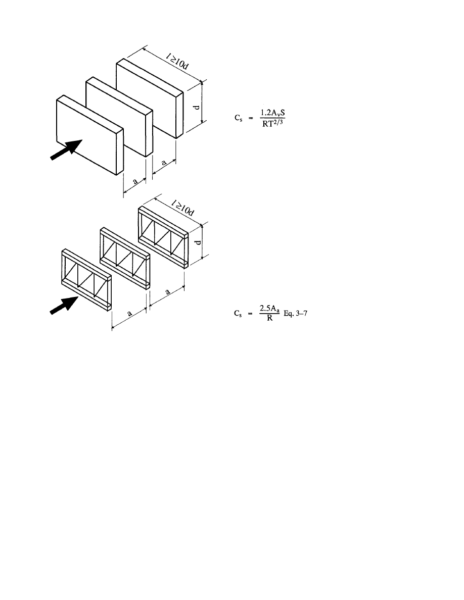
Shielding of multiple parallel elements can be de-
termined using the following equation taken from DIN
1055. See Figures 3.1 and 3.2.
Eq. 3-4
A
where
A = total
factored area
= a
stacking factor taken from Figure 3.2.
n = the
total
number of parallel elements
= the projected area of one element
The stacking factor,
is a function of the element
spacing to the element depth and a solidity ratio,
3.2.2 Seismic
Loads
As indicated in the AISC Code of Standard Prac-
tice, seismic forces are a load consideration in the de-
sign of temporary supports. In general, seismic forces
are addressed in building design by the use of an equiva-
lent pseudo-static design force. This force is a function
of:
1. an assessment of
the site specific seismic likelihood
and intensity,
4
© 2003 by American Institute of Steel Construction, Inc. All rights reserved.
This publication or any part thereof must not be reproduced in any form without permission of the publisher.
For the structures within the scope of this guide it is
unlikely that W would include any loads other than dead
load.
The seismic design coefficient, C
s
, is to be deter-
mined using the following equation:
Eq. 3-6
where
A
v
= a
coefficient
representing the peak velocity re-
lated acceleration taken from a contour map
supplied
S = a
coefficient for site soil profile characteristics
ranging from 1.0 to 2.0
R = a
response
modification factor, ranging from
1.5 to 8.0 depending on the structural system
and the seismic resisting system used
T = the
fundamental
period of the structure which
can be determined using equations provided
ASCE 7-93 states that the seismic design coeffi-
cient, C
s
, need not exceed the value given by the follow-
ing equation:
where
A
a
= a coefficient representing the effective peak ac-
celeration taken from a contour map supplied
R = the response modification factor described
above
For the structures within the scope of this guide the
response modification factor, R, would be 5.0. This val-
ue for R
w
is taken from ASCE 7, Table 9.3-2 and is the
value given for "Concentrically-braced frames". Like-
wise for the majority of regular structures there is not
significant penalty in using the simpler equation given
above to determine C
s
. The range of values in the con-
tour map provided in ASCE 7-93 are 0.05 through 0.40.
Thus, the range of values for C
s
is 0.025 to 0.20. In gen-
eral wind will govern the design of temporary supports
in areas of low seismic activity such as the mid-west.
Seismic forces will likely govern the design on the west
coast. The value of A
a
would be the same value used in
the design of the completed structure. Although this dis-
cussion of the determination of C
s
would apply to most
structures in the scope of this guide, it is incumbent on
the designer of the temporary support system to be
aware of the requirements for seismic design to confirm
that the general comments of this section apply to the
specific structure at hand.
Fig. 3.1 Parameters for Use
with Fig. 3.2
2. the use of the structure,
3. the geometry and framing system type of the struc-
ture,
4. the geological nature of the building site, and
5. the mass, i.e. self-weight of the structure.
Although codes and standards have differing ap-
proaches to seismic design, they are conceptually simi-
lar. The general approach can be seen in the description
of the approach used in ASCE 7-93 which follows.
The general equation for seismic base shear, V, is:
V = C
S
W Eq.3-5
where
C
s
= the
seismic
design
coefficient
W = the total dead load and applicable portions of
other loads
5
© 2003 by American Institute of Steel Construction, Inc. All rights reserved.
This publication or any part thereof must not be reproduced in any form without permission of the publisher.
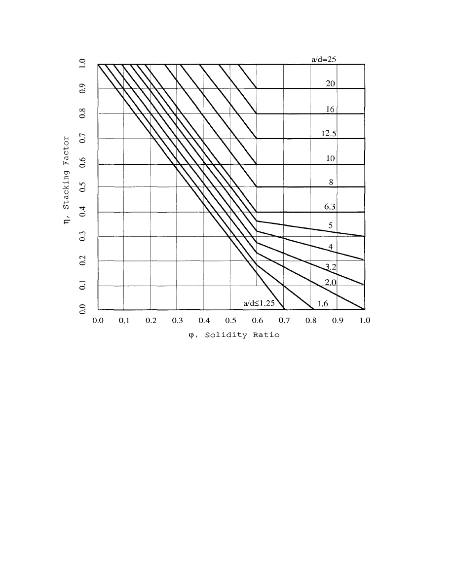
Fig. 3.2 Stacking Factor vs. Solidity Ratio
Based on the foregoing in general terms the pseu-
do-static force for seismic design is:
V = 0.05W to 0.40 W
depending on the structure's geographical location. It
should be noted that in this method the seismic base
shear, V, is a strength level value not an allowable stress
value. For single story buildings this force would be ap-
plied at the roof level. For multi-story buildings, a pro-
cedure is given to distribute the force at each story. In
many instances the distribution will be linear, however
in certain conditions of structure location and height the
distribution will be non-linear with the distribution
skewed to the upper stories. Non-linear distribution
will be required when the period of the structure exceeds
5 seconds. The period of the structure can be deter-
mined from equations given in ASCE-7.
For example, a 60-foot-tall structure located where
A
v
equals 0.4 would have a period T of 0.517 seconds.
Whereas a 60-foot-tall structure located where A
v
equals 0.05 would have a period T of 0.733 seconds.
A 40-foot-tall structure in the two locations would
have periods of 0.382 seconds and 0.540 respectively.
The higher periods in the low end of the A
v
range will
likely be of no consequence since the seismic force will
not likely be the governing force. The reader is referred
to ASCE 7-93 for the detailed presentation of vertical
distribution of seismic forces.
The horizontal distribution of seismic force is an
important consideration when seismic force is resisted
by elements in plan connected by longitudinal dia-
phragms or other horizontal systems. In the design of
temporary supports for lateral loads, each frame line
will generally have its own temporary supports so the
6
© 2003 by American Institute of Steel Construction, Inc. All rights reserved.
This publication or any part thereof must not be reproduced in any form without permission of the publisher.
horizontal distribution would consist of applying the
dead load, W, which is tributary to each frame.
3.3 Stability Loads
Columns supplied within standard mill practice and
erected within tolerance will have an eccentricity be-
tween the line of action of the applied load/column and
the line of action of the supporting resistance. This ec-
centricity produces a force couple or tipping moment
which must be resisted by a righting force, which can be
provided by base fixity, frame action or diagonal braces.
A common approach used in the design of bracing
for stability loads is to apply a horizontal load at each
level or story equal to 2 percent of the supported load. A
righting force of 2 percent is associated with a top of col-
umn displacement of one-fiftieth of the column height.
Since the maximum deviation from plumb per the AISC
Code of Standard Practice is one-five hundredth of the
column height, it can be seen that the 2 percent strength
criteria also accounts for second order forces due to dis-
placement in the bracing under load.
The 2 percent stability load was recommended by
the authors in a previous paper on the subject (11). It has
also been included in the Draft of the ASCE Standard for
Design Loads on Structures During Construction (6).
3.4 Erection Operation Loads
Loads are applied to the steel frame work as a con-
sequence of erection operations. Loads resulting from
hoists, jibs or derricks must be addressed in the bracing
design and in a check of the structure for the specific
reactions from these devices. These calculations must
include the magnitude of lifted loads and the reactions
on the framework.
Raising and securing individual pieces results in in-
cidental loads on the surrounding pieces. These small
loads are resisted by the minimum connections pro-
vided. If
significant prying, pulling or jacking is re-
quired, this should be evaluated prior to initiating these
operations. To account for incidental erection operation
lateral loading on the temporary supports, it is recom-
mended that a lateral load of 100 pounds per foot be ap-
plied to the perimeter of the framework. This was rec-
ommended by the authors in a previous paper (11) and is
included in the draft of the ASCE Standard, Design
Loads on Structures During Construction.
Lastly, the Steel Erection Negotiated Rulemaking
Advisory Committee (SENRAC) has recommended
that: "Column and anchor rod assemblies, including the
welding of the column to the base plate shall be designed
to resist a 300 pound (136.2 kg) eccentric load located
18 inches (.46 m) from the column face in each direction
at the top of the column shaft.".
Extraordinary loads such as those due to collisions
cannot be anticipated in the design and are excluded by
the AISC Code of Standard Practice.
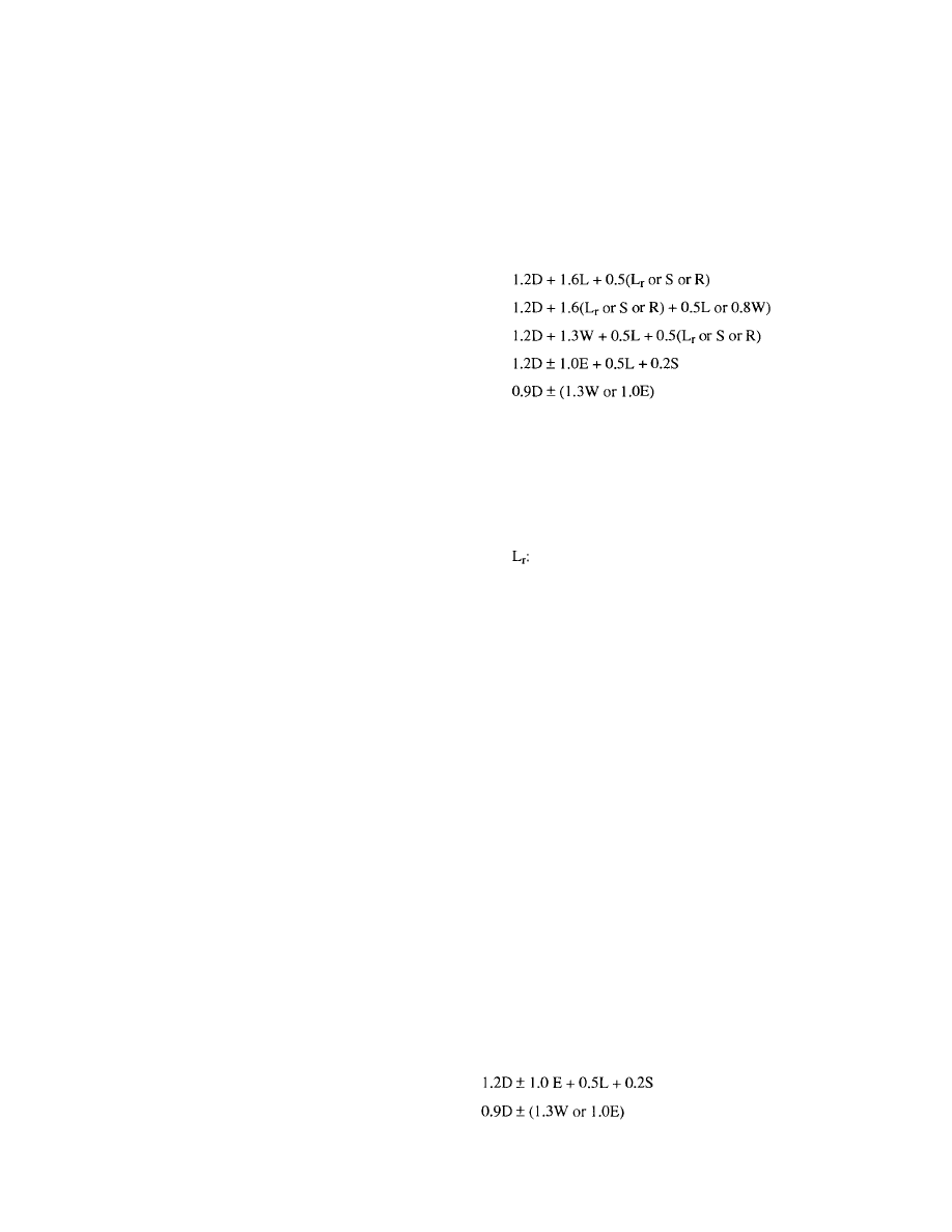
3.5 Load Combinations
Per paragraph A.4.1. of the LRFD Specification the
load combinations to be investigated in design are:
1.4D
The nominal loads to be considered are:
D: dead load due to the weight of the structural
elements and the permanent features on the
structure
L: live load due to occupancy and moveable
equipment
roof live load
W: wind load
S: snow
load
E: earthquake load determined in accordance
with Part I of the AISC Seismic Provisions for
Structural Steel Buildings(15)
R: load
due
to
initial rainwater or ice exclusive of
ponding contribution
Earlier in this guide, the procedure for calculation
of a seismic design base shear and its vertical and hori-
zontal distribution was discussed. Using the provisions
of ASCE-7 which adopts the NEHRP provisions results
in a base shear which is at a ".. .strength level, not an al-
lowable stress level".
Provisions for seismic design in steel are given in
"Seismic Provisions for Structural Steel Buildings"
published by AISC. In Part II - Allowable Stress Design
(ASD) Alternate, the "allowable stress" for members re-
sisting seismic forces ".. .acting alone or in combination
with dead and live loads shall be determined by multi-
plying 1.7 times the allowable stresses in [ASD Specifi-
cation] Sect. D, E, F, G, J and K". Thus for both ASD
and LRFD designs the load factors and combinations in
the LRFD Specification part A4 are appropriate, i.e.
Equations A4-5 and A4-6 which read:
These equations are the same as Equations 5 and 6 in
ASCE 7, paragraph 2.4.2. It should be noted that E is not
7
© 2003 by American Institute of Steel Construction, Inc. All rights reserved.
This publication or any part thereof must not be reproduced in any form without permission of the publisher.

the exact effect of the seismic force due to the seismic
base shear but must be modified by the following equa-
tions taken from ASCE 7, paragraph 9.3.7:
in Equation A4-5: E
and
in Equation A4-6:
E
where
E = the
effect
of
horizontal
and
vertical earthquake-
induced forces
A
v
= the coefficient representing effective peak ve-
locity-related acceleration from ASCE 7
D = the
effect
of
dead load, D
Q
E
= the effect of
horizontal seismic (earthquake-in-
duced) forces
The term 0.5 A
V
D is a corrective term to reconcile
the load factors used in the NEHRP requirements and
the load factors used in the ASCE 7/LRFD require-
ments. This correction is described in detail in the Com-
mentary to ASCE 7, which concludes that the correction
is made separately "...so that the original simplicity of
the load combination equations in Sec. 2 is maintained."
It is also explained in this paragraph taken from the
Commentary to the AISC Seismic Provisions:
"The earthquake load and load effects E in ASCE
7-93 are composed of two parts. E is the sum of the
seismic horizontal load effects and one half of A
v
times the dead load effects. The second part adds an
effect simulating vertical accelerations concurrent
to the usual horizontal earthquake effects."
In forming combinations containing the effects of
stability, the load factors for the load source (D or L)
which induces the PA effect would be used for the load
factor(s) on the effect of stability.
In the authors' earlier paper ( 1 1 ) on this topic the
following ASD combinations were recommended:
a. Stability
loading
b. 0.75
(stability
loading plus wind loading)
These combinations reflected the current ASD Specifi-
cation provision for one-third increases for stresses
computed for combinations including wind loading,
acting alone or in combination with dead and live load.
In this Guide the determination of load and resis-
tance is based on the LRFD Specification. Allowable
stress design is used only when LRFD procedures are
not available or would be inappropriate.
4. RESISTANCE TO CONSTRUCTION
PHASE LOADS BY THE PERMANENT
STRUCTURE
The resistance to loads during construction on the
steel framework is provided by a combination of the per-
manent work supplemented by temporary supports as
needed. The resistance of the permanent structure de-
velops as the work progresses. In a self-supporting
structure the resistance is complete when the erector's
work is complete. In a non-self-supporting structure
resistance will be required after the completion of the
erectors work and will be needed until the other non-
structural-steel elements are in place. During the erec-
tion of both self-supporting and non-self-supporting
frames, conditions will arise which require resistance to
be supplied by the partially completed work. If the re-
sistance of the partially completed work is not adequate,
it must be supplemented by temporary supports.
Elements of the permanent structure which may be
used to resist loads during construction are:
1. Columns
2. Column
Bases
3. Beams
and Joists
4. Diagonal
Bracing
5. Connections
6. Diaphragms
Columns
In general columns will have the same unbraced
length in the partially completed work as in the com-
pleted work so their axial design strength would be the
same during erection as the completed work. The ex-
ceptions would be:
Columns which are free standing on their bases be-
fore other framing and bracing is installed.
Columns supported on leveling nuts or shims prior
to grouting.
Columns which are to be laterally braced by girts or
struts.
Columns which have additional axial load due to
the temporary support system.
Column Bases
The column bases of the permanent structure are an
essential element of both the permanent structure and
the temporary support system. The column bases trans-
fer vertical and lateral loads from the structural steel
framework to the foundation and thence to the ground.
The components of a column base are:
8
© 2003 by American Institute of Steel Construction, Inc. All rights reserved.
This publication or any part thereof must not be reproduced in any form without permission of the publisher.

the base plate and its attachment to the column shaft
the anchor rods
the base plate grout
the supporting foundation.
Base Plate: Column base plates are square or rectangu-
lar plates which transfer loads from the column shaft to
the foundation. In high-rise construction and in other
cases of very high loading, large column bases are some-
times shipped and set separately from the column shafts.
In the case of low-rise and one story buildings, the base
plates are usually shipped attached the column shafts.
The column base reaction is transferred to the column
by bearing for compression forces and by the column to
base plate weld for tension and shear.
Anchor Rods: Anchor rods have in the past been called
anchor bolts. This Design Guide uses the term anchor
rod which has been adopted by AISC in the 2nd edition
of the LRFD Manual of Steel Construction to distin-
guish between bolts, which are generally available in
lengths up to eight inches, and longer headed rods, such
as threaded rods with a nut on the end, and hooked rods.
In the completed construction (with the base plates
grouted) anchor rods are designed to carry tension
forces induced by net tension in the column, base bend-
ing moments and tension induced by shear friction re-
sisting column base shears. During erection operations
and prior to base plate grouting, anchor rods may also
resist compression loads and shears depending on the
condition of temporary support for the column and the
temporary lateral support system. Anchor rods are em-
bedded in the cast-in-place foundation and are termi-
nated with either a hook or a headed end, such as a heavy
hex nut with a tack weld to prevent turning.
Base Plate Grout: High strength, non-shrink grout is
placed between the column base plate and the support-
ing foundation. Where base plates are shipped loose,
the base plates are usually grouted after the plate has
been aligned and leveled. When plates are shipped at-
tached to the column, three methods of column support
are:
1. The
use
of
leveling nuts and, in some cases,
washers on the anchor rods beneath the base
plates.
2. The use of shim stacks between the base plate
bottoms and top of concrete supports.
3. The use of 1/4" steel leveling plates which are
set to elevation and grouted prior to the setting
of columns.
Leveling nuts and shim stacks are used to transfer
the column base reactions to the foundation prior to the
installation of grout. When leveling nuts are used all
components of the column base reaction are transferred
to the foundation by the anchor rods. When shims are
used the compressive components of the column base
reaction are carried by the shims and the tension and
shear components are carried by the anchor rods.
Leveling nuts bear the weight of the frame until
grouting of the bases. Because the anchor rod, nut and
washers have a finite design strength, grouting must be
completed before this design strength would be exceed-
ed by the accumulated weight of the frame. For exam-
ple, the design strength of the leveling nuts may limit the
height of frame to the first tier of framing prior to grout-
ing. Also, it is likely that the column bases would have
to be grouted prior to placing concrete on metal floor
deck.
Properly installed shim stacks can support signifi-
cant vertical load. There are two types of shims. Those
which are placed on (washer) or around (horseshoe) the
anchor rods and shim stacks which are independent of
the anchor rods. Shims placed on or around the anchor
rods will have a lesser tendency to become dislodged.
Independent shims must have a reasonable aspect ratio
to prevent instability of the stack. In some instances
shim stacks are tack welded to maintain the integrity of
the stacks. When shim stacks are used, care must be tak-
en to insure that the stacks cannot topple, shift or be-
come dislodged until grouting. Shims are sometimes
supplemented with wedges along the base plate edges to
provide additional support of the base plate.
Pregrouted leveling plates eliminate the need to
provide temporary means for the vertical support for the
column. The functional mechanisms of the base are the
same in the temporary and permanent condition once
the anchor rod nuts are installed.
The design of base plates and anchor rods is treated
extensively in texts and AISC publications such as the
Manual of Steel Construction and AISC Design Guides
1(7) and 7(10).
Foundations: Building foundations are cast-in-place
concrete structures. The
element
which usually re-
ceives the anchor rods may be a footing, pile cap, grade
beam, pier or wall. The design requirements for cast-
in-place concrete are given in building codes which
generally adopt the provisions of the American Con-
crete Institute standards such as ACI 318 "Building
Code Requirements for Reinforced Concrete and Com-
mentary"(3). The principal parameter in the design and
evaluation of cast-in-place concrete is the 28-day cyl-
inder compression stress, f'
c
. Axial
compressive
strength, flexural strength, shear strength, reinforcing
bar development and the development of anchor rods
are a function of the concrete compressive strength, f'
c
.
Axial tension and flexural tension in concrete elements
is carried by deformed reinforcing bars to which force is
transferred by development of the bar which is a func-
tion of an average bond stress. Bar development is a
function of concrete strength, reinforcement strength,
bar size, bar spacing, bar cover and bar orientation.
9
© 2003 by American Institute of Steel Construction, Inc. All rights reserved.
This publication or any part thereof must not be reproduced in any form without permission of the publisher.

Columns are sometimes supported on masonry pi-
ers rather than concrete piers. In this case the strength of
the piers would be evaluated using ACI 530 "Building
Code Requirements for Masonry Structures" (2) or
another comparable code. Masonry is constructed as
plain (unreinforced) or reinforced. Unreinforced ma-
sonry construction has very low tensile strength and thus
unguyed cantilevered columns would be limited to
conditions where relatively little base moment resis-
tance is required. Reinforced masonry can develop
strengths comparable to reinforced concrete. The ma-
sonry enclosing the grout and reinforcement must be
made large enough to also accommodate and develop
the anchor rods.
In some instances steel columns are erected on
bases atop concrete or masonry walls. In these condi-
tions the side cover on the anchor rods is often less than
it would be in a pier and significantly less than it would
be in the case of a footing. Although not specifically ad-
dressed in this guide, the design strength of the anchor
rod can be determined based on the procedures provided
in this Guide in conjunction with the requirements of
ACI 318 or ACI 530 as appropriate. The wall itself
should be properly braced to secure it against loads im-
posed during the erection of the steel framing.
The erection operation, sequence of the work, reac-
tions from temporary supports and the timing of grout-
ing may cause forces in the anchor rods and foundation
which exceed those for which the structure in its com-
pleted state has been designed. This Guide provides
procedures to evaluate the anchor rods and foundation
for such forces.
One condition of loading of the column base and
foundation occurs when a column shaft is set on the an-
chor rods and the nuts are installed and tightened. Un-
less there is guying provided, the column is a cantilever
from the base and stability is provided by the develop-
ment of a base moment in the column base. This condi-
tion is addressed in detail subsequently in this Guide.
Diagonal cables for temporary lateral support also
induce tensions and shears in the column base which
must be transferred from the column base, through the
anchor rods to the foundation.
Lastly, the structural frame when decked may be
subject to wind uplift which is not counterbalanced by
the final dead load. A net uplift in the column base may
induce forces in the base plates and welds, anchor rods,
and foundation which exceed those for which the struc-
ture in its completed state was designed.
Beams and Joists
Framing members on the column center lines act as
tie members and struts during erection. As such they are
subject to axial forces as well as gravity load bending. In
most cases the axial compression strength of tie mem-
bers and struts will be limited by their unbraced length in
the absence of the flange bracing. The resistance of strut
and tie members must be evaluated with the lateral brac-
ing in place at the time of load application.
Diagonal Bracing
Permanent horizontal and vertical bracing systems
can function as temporary bracing when they are initial-
ly installed. When a bracing member is raised, each end
may only be connected with the minimum one bolt, al-
though the design strength may be limited by the hole
type and tightening achieved. The
bracing design
strength may also be limited by other related conditions
such as the strength of the strut elements or the base con-
nection condition. For example, the strut element may
have a minimum of two bolts in each end connection,
but it may be unbraced, limiting its strength.
Connections
Structural steel frames are held together by a multi-
tude of connections which transfer axial force, shear and
moment from component to component. During erec-
tion connections may likely be subjected to forces of a
different type or magnitude than that for which they
were intended in the completed structure. Also, connec-
tions may have only some of the connectors installed
initially with the remainder to be installed later. Using
procedures presented in texts and the AISC Manual of
Steel Construction the partially complete connections
can be evaluated for adequacy during erection.
Diaphragms
Roof deck and floor deck (slab) diaphragms are fre-
quently used to transfer lateral loads to rigid/braced
framing and shear walls. Diaphragm strength is a func-
tion of the deck profile and gage, attachments to sup-
ports, side lap fastening and the diaphragm's anchorage
to supporting elements, i.e., frames and shear walls.
Partially completed diaphragms may be partially effec-
tive depending on the diaphragm geometry, extent of at-
tachment and the relation of the partially completed sec-
tion to the supporting frames or walls. Partially
completed diaphragms may be useful in resisting erec-
tion forces and stabilizing strut members, but the degree
of effectiveness must be verified in the design of the
temporary support system analysis and design.
4.1 Columns
Exceptions were listed earlier wherein the columns
may not have the same length as they would in the com-
pleted structure. Before using the permanent columns
in the temporary support system the erector must evalu-
ate whether the columns have the required strength in
the partially completed structure.
Specific guidelines for this evaluation are not pres-
ented here, because of the many variables that can oc-
10
© 2003 by American Institute of Steel Construction, Inc. All rights reserved.
This publication or any part thereof must not be reproduced in any form without permission of the publisher.
cur. Basic structural engineering principles must be ap-
plied to each situation.
4.2 Column Bases
Probably the most vulnerable time for collapse in
the life of a steel frame occurs during the erection se-
quence when the first series of columns is erected. After
the crane hook is released from a column and before it is
otherwise braced, its resistance to overturning is depen-
dent on the strength (moment resistance) of the column
base and the overturning resistance of the foundation
system. Once the column is braced by tie members and
bracing cables it is considerably more stable.
It is essential to evaluate the overturning resistance
of the cantilevered columns. Cantilevered columns
should never be left in the free standing position unless it
has been determined that they have the required stability
to resist imposed erection and wind loads.
In order to evaluate the overturning resistance one
must be familiar with the modes of failure which could
occur. The most likely modes of failure are listed below.
It is not the intent of this design guide to develop struc-
tural engineering equations and theories for each of
these failure theories, but rather to provide a general
overview of each failure mode and to apply existing
equations and theories. Equations are provided to obtain
the design strength for each mode based on structural
engineering principles and the AISC LRFD Specifica-
tion.
Modes of Failure:
1. Fracture
of
the
fillet weld that connects the column
to the base plate.
2. Bending failure of the base plate.
3. Tension
rupture of the anchor rods.
4. Buckling
of
the
anchor
rods.
5. Anchor
rod
nut
pulling or pushing through the base
plate hole.
6. Anchor rod "pull out" from the concrete pier or
footing.
7. Anchor
rod
straightening.
8. Anchor
rod
"push out" of the bottom of the footing.
9. Pier
spalling.
10. Pier bending failure.
11. Footing overturning.
For a quick determination of the resistance for each
of the failure modes, tables are presented in the Appen-
dix.
11
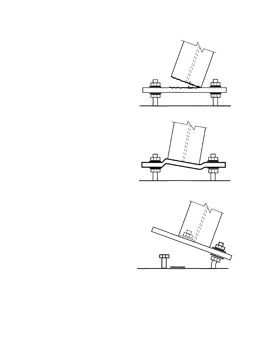
4.2.1
Fracture of the Fillet Weld Connecting the
Column to the Base Plate.
Cantilevered columns are subjected to lateral erec-
tion and wind forces acting about the strong and/or the
weak axis of the column. Weld fractures between the
column base and the base plate are often found after an
erection collapse. In the majority of cases the fractures
Fig. 4.3 Rupture of Anchor Rods
Fig. 4.2 Bending Failure of Base Plate
Figures 4.1 through 4.11 shown below represent each of
the failure modes.
Fig. 4.1 Fracture of Weld
© 2003 by American Institute of Steel Construction, Inc. All rights reserved.
This publication or any part thereof must not be reproduced in any form without permission of the publisher.
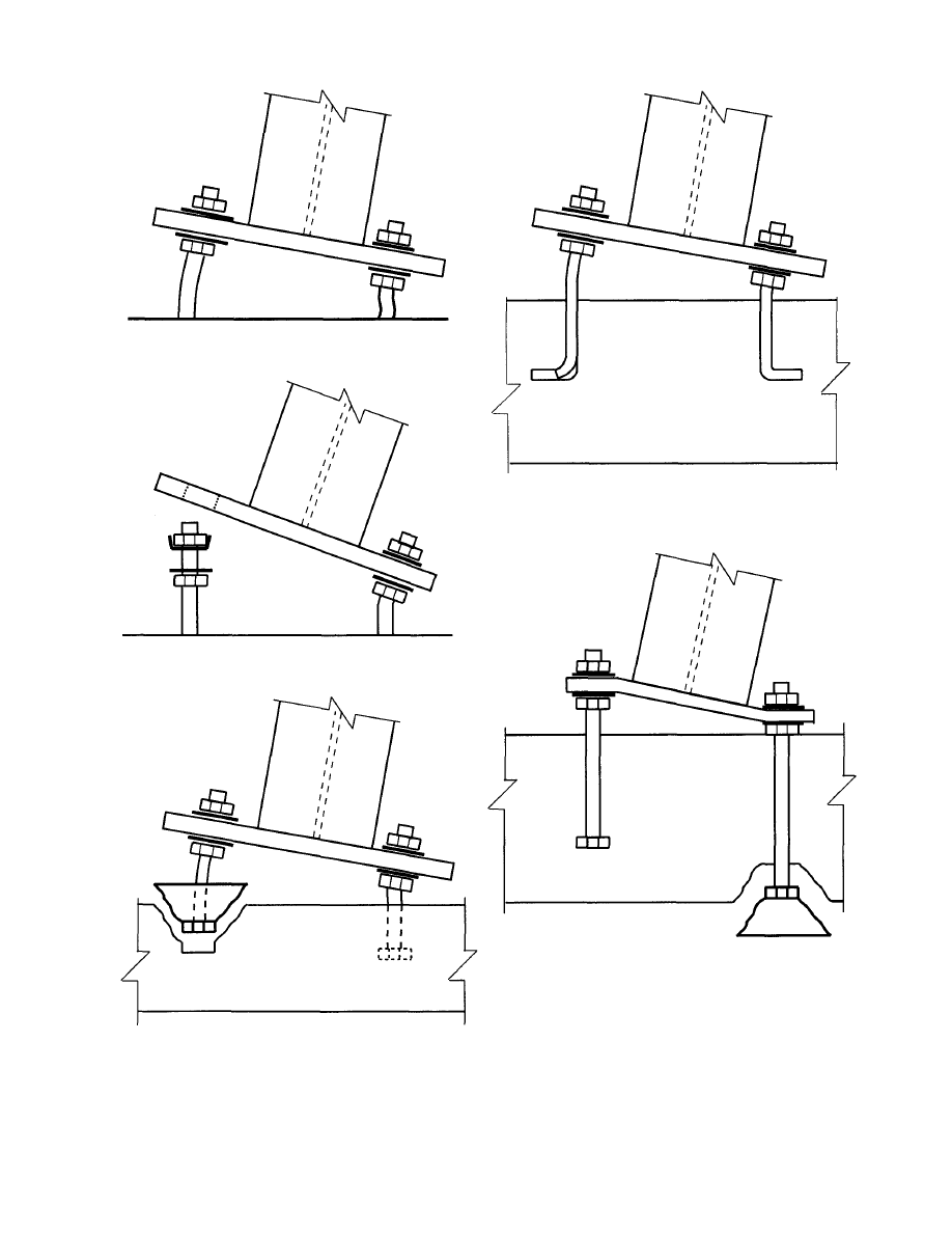
Fig. 4.4 Anchor Rod Buckling
Fig. 4.7 Anchor Rod Straightening
Fig. 4.5 Anchor Rod Pull Through
Fig. 4.6 Anchor Rod Pull Out
Fig. 4.8 Anchor Rod Push Out
are secondary, i.e. some other mode of failure initiated
the collapse, and weld failure occurred after the initial
failure. Fracture occurs when the weld design strength is
exceeded. This normally occurs for forces acting about
the weak axis of the column, because the strength of the
12
weld group is weaker about the weak axis, and because
the wind forces are greater when acting against the weak
axis, as explained earlier.
The design strength of the weld between the col-
umn and the base plate can be determined by calculating
the bending design strength of the weld group. Applied
© 2003 by American Institute of Steel Construction, Inc. All rights reserved.
This publication or any part thereof must not be reproduced in any form without permission of the publisher.
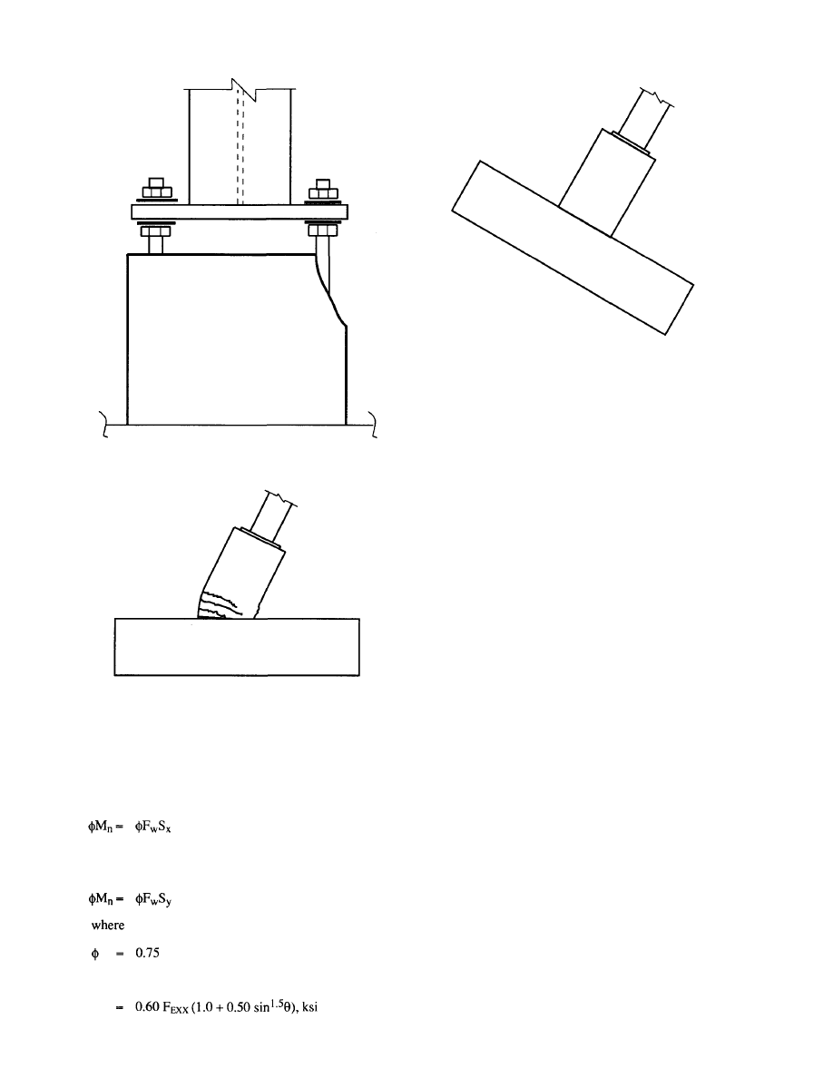
Fig. 4.9 Pier Spalling
Fig. 4.10 Pier Bending Failure
shear forces on the weld are small and can be neglected
in these calculations.
For bending about the column strong axis the de-
sign strength of the weld group is:
Eq. 4-1
For bending about the column weak axis the design
strength of the weld group is:
Eq. 4-2
F
w
= the nominal weld stress, ksi
13
Fig. 4.11 Footing Overturning
= 1.5(0.60) F
E X X
, ksi (for 90° loading)
F
E X X
= electrode classification number, i.e. minimum
specified strength, ksi
S
x
= the
section
modulus of the weld group about its
strong axis, in.
3
S
y
= the
section
modulus of the weld group about its
weak axis, in.
3
4.2.2 Bending Failure of the Base Plate.
Ordinarily a bending failure is unlikely to occur.
Experience has shown that one of the other modes of
failure is more likely to govern. A bending failure re-
sults in permanent bending distortion (yielding) of the
base plate around one or more of the anchor rods. The
distortion allows the column to displace laterally, result-
ing in an increased moment at the column base, and
eventual collapse. The design strength of the base plate
is dependent on several variables, but it primarily de-
pends on the base plate thickness, the support points for
the base plate, and the location of the anchor rods.
The design strength of the base plate can be conser-
vatively determined using basic principles of strength of
materials.
Case A: Inset Anchor Rods - Wide Flange Columns.
Yield line theories can be used to calculate the
bending design strength of the base plate for moments
about the x and y axes. The lowest bound for all possible
yield lines must be determined. The approach used here
is a simplification of yield line theory and is conserva-
tive.
The design strength of the base plate is determined
using two yield lines. Shown in Figure 4.12 are the two
yield line lengths used, b
1
and b
2
- The length b
1
is taken
as two times d
1
, the distance of the anchor rod to the cen-
© 2003 by American Institute of Steel Construction, Inc. All rights reserved.
This publication or any part thereof must not be reproduced in any form without permission of the publisher.
Fig. 4.13 Base Plate with Leveling Nuts
ter of the column web. The length b
2
is taken as the
flange width divided by two. The yield line b
2
occurs as
a horizontal line through the bolt Centerline.
Using the dimensions shown in Figure 4.12, the de-
sign strength for a single anchor rod is:
Eq. 4-3
where
the anchor rod force which causes the base plate
to reach its design strength, kips
the plastic moment resistance based on b
1
in.-
kips
the plastic moment resistance based on b
2
, in.-
kips
Fig. 4.15 Effective Width
Currently the AISC standard detail illustrates weld
only along the flanges, unless shown otherwise on the
contract drawings. The addition of a fillet weld along
one side of the web adds considerable strength to the
14
Fig. 4.14 Base Plate with Shim Stacks
Fig. 4.12 Base Plate Dimensions
= 0.90
Eq. 4-3 is based on d
1
and d
2
being approximately
equal.
After determining the
design strength of the
base plate is determined by multiplying
by the ap-
propriate lever arm, d or g
is multiplied by two if the
base condition consists of two anchor rods in tension).
Eq.4-4
If leveling nuts are used under the base plate the le-
ver arm (d) is the distance between the anchor rods. See
Figure 4.13. If shim stacks are used then the lever arm
(d) is the distance from the anchor rods to the center of
the shim stack. See Figure 4.14. See discussion of the
use of shims at the beginning of this section.
© 2003 by American Institute of Steel Construction, Inc. All rights reserved.
This publication or any part thereof must not be reproduced in any form without permission of the publisher.
connection. Without the web weld only the length b
2
would be used in the strength calculations.
Case B: Outset Rods - Wide Flange Columns
The authors are unaware of any published solutions
to determine base plate thickness or weld design
strength for the base plate - anchor rod condition shown
in Figure 4.15. By examining Figure 4.15 it is obvious
that the weld at the flange tip is subjected to a concentra-
tion of load because of the location of the anchor rod.
The authors have conducted elastic finite element anal-
ysis in order to establish a conservative design proce-
dure to determine the required base plate thickness and
weld design strength for this condition. The following
conclusions are based on the finite element studies:
1. The
effective
width of the base plate, b
e
, should
be taken as 2L.
2. The
maximum
effective width to be used is
five inches.
3. A
maximum
weld
length of two inches can be
used to transmit load between the base plate
and the column section. If weld is placed on
both sides of the flange then four inches of
weld can be used.
4. The base plate thickness is a function of the
flange thickness so as not to over strain the
welds.
In equation format the design strength for a single
anchor rod can be expressed as follows:
Eq. 4-5
Eq. 4-6
Eq. 4-7
Based on the plate effective width:
Based on weld strength:
Based on weld strain:
where
= 0.90
= 0.75
b
e
= the
effective
plate width, in.
L = the distance of the anchor rod to the flange tip,
in.
t =
the
throat
width of the weld, in.
t
p
= the
base
plate
thickness, in.
F
y
= the specified yield strength for the base plate,
ksi
F
w
= the nominal weld stress, ksi
= 0.9
FEXX,
ksi
(90° loading)
FEXX = electrode classification number, ksi
Using the controlling value for
and d:
Eq. 4-8
Case C Outset Rods with hollow structural section
(HSS) columns.
When hollow structural section (HSS) columns are
used, Eq. 4-5 and Eq. 4-7 can be used to calculate
however, if fillet welds exist on all four sides of the col-
umn, then four inches of weld length at the corner of the
HSS can be used for the calculation of
in Eq. 4-6.
Thus:
Eq.4-9
4.2.3 Rupture
of
Anchor
Rods
A tension rupture of the anchor rods is often ob-
served after an erection collapse. This failure occurs
when the overturning forces exceed the design strength
of the anchor rods. Fracture usually occurs in the root of
the anchor rod threads, at or flush with, the face of the
lower or upper nut. Anchor rod rupture may be precipi-
tated by one of the other failure modes. It is generally
observed along with anchor rods pulling out of the con-
crete pier, or footing. Shown in Figure 4.3 is an anchor
rod tension failure. The tension rupture strength for rods
is easily determined in accordance with the AISC speci-
fication.
Eq. 4-10
where
= 0.75
(Table J3.2)
= the
tension
rod
design
strength,
kips
F
n
= nominal
tensile strength of the rod F
t
, ksi
F
t
= 0.75F
U
(Table J3.2)
F
u
= specified
minimum tensile strength, ksi
A
b
= nominal unthreaded body area of the anchor
rod, in.
2
For two anchor rods in tension the bending design
strength can again be determined as:
Eq. 4-11
4.2.4 Buckling of the Anchor Rods
The buckling strength of the anchor rods can be cal-
culated using the AISC LRFD Specification (Chapter
15
© 2003 by American Institute of Steel Construction, Inc. All rights reserved.
This publication or any part thereof must not be reproduced in any form without permission of the publisher.

E). For base plates set using leveling nuts a reasonable
value for the unbraced length of the anchor rods is the
distance from the bottom of the leveling nut to the top of
the concrete pier or footing. When shim stacks are used
the anchor rods will not buckle and this failure mode
does not apply. It is suggested that the effective length
factor, K, be taken as 1.0, and that the nominal area (A
b
)
be used for the cross sectional area.
For anchor rod diameters greater than 3/4 inches
used in conjunction with grout thickness not exceeding
8 inches, the authors have determined that buckling
strength of the anchor rods will always exceed the de-
sign tensile strength of the rods. Thus this failure mode
need not be checked for most situations.
4.2.5 Anchor Rod Pull or Push Through
The nuts on the anchor rods can pull through the
base plate holes, or when leveling nuts are used and the
column is not grouted, the base plate can be pushed
through the leveling nuts. Both failures occur when a
washer of insufficient size (diameter, thickness) is used
to cover the base plate holes. No formal treatise is pres-
ented herein regarding the proper sizing of the washers;
however, as a rule of thumb, it is suggested that the
thickness of the washers be a minimum of one third the
diameter of the anchor rod, and that the length and width
of the washers equal the base plate hole diameter plus
one inch.
Special consideration must be given to base plate
holes which have been enlarged to accommodate mis-
placed anchor rods.
4.2.6 Anchor
Rod
Pull
Out
Shown in Figure 4.6 is a representation of anchor rod
pull out.
This failure mode occurs when an anchor rod (a
hooked rod or a nutted rod) is not embedded sufficiently
in the concrete to develop the tension strength of the rod.
The failure occurs in the concrete when the tensile
stresses along the surface of a stress cone surrounding
the anchor rod exceed the tensile strength of the con-
crete. The extent of the stress cone is a function of the
embedment depth, the thickness of the concrete, the
spacing between the adjacent anchors, and the location
of free edges of in the concrete. This failure mode is
presented in detail in Appendix B of ACI 349-90(4).
The tensile strength of the concrete, in ultimate strength
terms, is represented as a uniform tensile stress of
over the surface area of these cones. By examin-
ing the geometry, it is evident that the pull out strength
of a cone is equal to
times the projected area, A
e
,
of the cone at the surface of the concrete, excluding the
area of the anchor head, or for the case of hooked rods
the projected area of the hook.
The dotted lines in Figure 4.16 represent the failure
cone profile. Note that for the rods in tension the cones
will be pulled out of the footing or pier top, whereas the
cones beneath the rods in compression will be pushed
out the footing bottom. This latter failure mode will be
discussed in the next section.
Depending on the spacing of the anchor rods and
the depth of embedment of the rods in the concrete, the
failure cones may overlap. The overlapping of the fail-
ure cones makes the calculation of A
e
more complex.
Based on AISC's Design Guide 7 the following
equation is provided for the calculation of A
e
which
covers the case of the two cones overlapping.
where
L
d
= the embedment depth, in.
c = the rod diameter for hooked rods, in., and 1.7
times the rod diameter for nutted rods (the 1.7
factor accounts for the diameter of the nut)
s
= the rod spacing, in.
Thus, the design strength of two anchor rods in tension
is:
Eq. 4-13
where
- 0.85
f'
c
= the
specified concrete strength, psi
When the anchor rods are set in a concrete pier, the
cross sectional area of the pier must also be checked.
Conservatively, if the pier area is less than A
e
then the
pier area must be used for A
e
in the calculation of
(Eq.4-13).
Also when anchor rods are placed in a pier the proj-
ected area of the cone may extend beyond the face of the
pier. When this occurs A
e
must be reduced. The pullout
strength can also be reduced by lateral bursting forces.
The failure mode shown in Figure 4.9 is representative
of these failure modes. These failure modes are also dis-
cussed in AISC's Design Guide 7. Conservatively A
e
can be multiplied by 0.5 if the edge distance is 2 to 3 in-
ches.
It is recommended that plate washers not be used
above the anchor rod nuts. Only heavy hex nuts should
be used. Plate washers can cause cracks to form in the
concrete at the plate edges, thus reducing the pull out re-
sistance of the anchor rods. The heavy hex nuts should
16
© 2003 by American Institute of Steel Construction, Inc. All rights reserved.
This publication or any part thereof must not be reproduced in any form without permission of the publisher.
Per ACI 318, (0.70) is the factor for bearing on con-
crete, and the value (2) represents the strength increase
due to confinement.
The design strength obtained from Eq. 4-14 must
be compared to the strength obtained from the failure
cones, Eq. 4-13. The lower value provides the ultimate
strength of the hooked rod to be used in the calculation
for the bending moment design strength associated with
rod pull out.
Eq. 4-15
4.2.7 Anchor
Rod
"Push
Out"
of
the
Bottom
of
the
Footing
Anchor rod push out can occur when the rod is
loaded to the point where a cone of concrete below the
anchor rod is broken away from the footing. This failure
mode is identical to anchor rod pull out but is due to a
compressive force in the rod rather than a tension force.
This failure mode does not occur when shim stacks are
used, when piers are present or when an additional nut is
placed on the anchor rods just below the top of the foot-
ing as shown in Figure 4.17.
Fig. 4.17 Prevention of Push Out
Shown in Figure 4.18 is the individual failure cone
for a nutted anchor rod, and the equation for A
e
. The de-
sign strength for this mode of failure is:
Fig. 4.18 Push Out Cones
Eq. 4-16
where
.75
f'
c
= the
concrete compressive strength, psi
17
SECTION A
Fig. 4.16 Failure Cones
be tack welded to the anchor rods to prevent the rod from
turning during tightening operations.
For hooked anchor rods an additional check must be
made, because hooked rods can fail by straightening and
pulling out of the concrete. When this occurs, the rods
appear almost perfectly straight after failure. To prevent
this failure mode from occurring the hook must be of
sufficient length. The hook pullout resistance can be de-
termined from the following equation:
Eq.4-14
where
Hook Bearing Design Strength, kips
f'
c
= the
concrete compressive strength, psi
the diameter of the anchor rod, in.
the length of the hook, in.
© 2003 by American Institute of Steel Construction, Inc. All rights reserved.
This publication or any part thereof must not be reproduced in any form without permission of the publisher.
The push out design strength for hooked anchor rods is
assumed to equal that of the nutted rod.
4.2.8 Pier
Bending
Failure
The design strength of a reinforced concrete pier in
bending is calculated using reinforced concrete prin-
ciples. The required procedure is as follows:
Determine the depth of the compression area.
C = T
0.85f'
c
ba = F
y
A
s
a
C - 0.85f'
c
ab
d = the
effective
depth of the tension reinforcing
= pier
depth
- cover - 1/2 of the bar diameter
C(d-a/2) Eq.
4-17
In addition, to insure that the reinforcing steel can
develop the moment, the vertical reinforcement must be
fully developed. Based on ACI 318-95 (12.2.2.), the re-
quired development length can be determined from the
equations below. These equations presume that ACI col-
umn ties, concrete cover, and minimum spacing criteri-
on are satisfied.
For the hooked bar in the footing:
Eq. 4-18
For straight bars (#6 bars and smaller) in the pier:
Eq. 4-19
For straight bars (#7 bars and greater) in the pier:
Eq. 4-20
where
1
d h
= the
development
length
of standard hook in ten-
sion, measured from critical section to out-side
end of hook, in. (See Figure 4.19)
1
d
= development
length, in.
f'
c
= specified
concrete strength, psi
d
b
= the bar diameter, in.
If the actual bar embedment length is less than the
value obtained from these equations then the strength
requires further investigation. See ACI 318, Chapter 12.
4.2.9 Footing
Over
Turning
The resistance of a column footing to overturning is
dependent on the weight of the footing and pier, if any,
the weight of soil overburden, if any, and the length of
Fig. 4.19 Development Lengths
the footing in the direction of overturning. During
construction the overburden, backfill, is often not pres-
ent and thus is not included in this overturning calcula-
tion.
Shown in Figure 4.11 is a footing subjected to an
overturning moment.
The overturning resistance equals the weight, W
times the length, L divided by two, i.e.:
Eq. 4-21
where
= 0.9
W = P1+P2
+
P3
P1 = the
weight
of
any
superimposed loads, kips
P2 = the weight
of
the pier, if any, kips
P3 = the weight of the footing, kips
After determining each of the individual design
strengths, the lowest bending moment strength can be
compared to the required bending moment to determine
the cantilevered column's suitability.
Example 4-1:
Determine the overturning resistance of a Wl2X65, free
standing cantilever column. Foundation details are
shown in Figure 4.20, and base plate details are shown in
Figure 4.21.
Given:
Leveling Nuts and Washers
4-3/4" ASTM A36 Hooked Anchor Rods with 12"
Embedment and 4" Hook
Pier 1'-4" x 1'-4" with 4 - #6 Vert, and #3 Ties @ 12" o/c
Footing 6'-0" x 6'-0" x l'-3"
18
© 2003 by American Institute of Steel Construction, Inc. All rights reserved.
This publication or any part thereof must not be reproduced in any form without permission of the publisher.
Fig. 4.20 Foundation Detail
Failure Mode 2: Base Plate Failure
Case B: Inset Anchor Rods - Weak Axis Capacity.
Based on the weld pattern and the geometry provided:
(See Figure 4.12)
Fig. 4.21 Base Plate Detail
No Overburden
Material Strengths:
Plates: 36 ksi
Weld Metal: 70 ksi
Reinforcing Bars: 60 ksi
Concrete: 3 ksi
Solution:
Failure Mode 1: Weld Design Strength
Compute
(Neglecting Web Weld):
Failure Mode 3: Rupture of Anchor Rods
where
Failure Mode 4: Anchor Rod Buckling (Does not gov-
ern). (See Section 4.2.4.)
Failure Mode 5: Anchor Rod Nut Pull Through (Use
proper washers to eliminate this failure mode.)
19
© 2003 by American Institute of Steel Construction, Inc. All rights reserved.
This publication or any part thereof must not be reproduced in any form without permission of the publisher.
Failure Mode 6: Anchor Rod Pullout
= 628 in.
2
Check Pier Area:
A
e
= 16(16) = 256 in.
2
(Controls)
Note that edge distance will not control.
Check Hook Bearing Strength:
(Eq. 4-14)
= 2(0.7)(0.85)(3000)(0.75)(4)
= 10.7
kips
= 21.4 kips for two rods (Controls)
(Eq. 4-15)
= 8.9ft.-kips
Failure Mode 7 : Anchor Rod Push Out (Does not oc-
cur with pier.)
Failure Mode 8 : Pier Bending Resistance
Determine the depth of the compression area:
Failure Mode 9: Footing Overturning
(Eq.4-21)
where
0.9
W = P1+P2
+
P3
P1 = 65(40)7 1000 = 2.6 kips (Column)
P2 = 0.15(1.33)1.33(3) = 0.8 kips (Pier)
P3 = 0.15(1.25)6(6)
=
6.75 kips (Footing)
W = 10.15
kips, L = 6ft.
0.9(10.15)(6/2) = 27.4 ft. - kips
Comparing the above failure modes, the design moment
strength is 8.9 ft.-kips. The governing failure mode
would be anchor rod pull out.
Example 4-2:
Repeat Example 4-1 using outset anchor rods with em-
bedded nuts.
Increase the pier size to 24" x 24" to accommodate the
base plate. Increase the vertical reinforcement to be
8—#6 bars. The distance from the anchor rod to the
flange tip, L equals 2.83 in.
BasePlate 1" x 20" x l'-8"
= 60,000(2)(0.44)/0.85(3000)(16)
= 1.294 in.
C = 0.85f'
c
a
= 0.85(3000)(16)(1.294)71000
= 52.8
kips
= 52.8(13.75-1.294/2)
= 58
ft.-kips
Check Reinforcing Development length:
Req'd length in footing:
C(d-a/2) = 692 in.- kips
(Eq. 4-17)
For the straight bars (#6 bars and smaller) in the pier:
20
(Eq. 4-5)
Failure Mode 2: Base Plate Failure
b
e
= 2L
= 5.66 in. > 5.0 in.
Fig. 4.23 Base Plate Detail
Solution:
Failure Mode 1: Weld Design Strength
kips (Same as Example 4-1)
© 2003 by American Institute of Steel Construction, Inc. All rights reserved.
This publication or any part thereof must not be reproduced in any form without permission of the publisher.
Fig. 4.24 Base Plate Yield Line
= (0.9)(5)(l)
2
(36)/[(4)(5)]
= 16.2
kips
= (0.75)(0.9)(70)(.707)(5/16)(2)
= 20.9
kips
(Eq. 4-6)
(Eq. 4-7)
= (0.9)(50)(.221)(1)
1.5
- 9.94
kips
(Controls)
= 2(9.94)( 16) = 318 in.-kips
= 26.5ft.-kips
Failure Mode 3: Rupture of Anchor Rods
(Eq. 4-8)
14.4 kips/rod ( Same as Example 1)
(Eq.4-11)
= 2(14.4)(
16)= 461 in.-kips
= 38.4
ft.-kips
Failure Mode 4: Anchor Rod Buckling (Does not gov-
ern)
Failure Mode 5: Anchor Rod Nut Pull Over (Use proper
washers)
Failure Mode 6: Anchor Rod Pull Out
(Eq. 4-13)
21
By inspection the pier area will control.
Check Pier Area:
A
e
= 20(20) = 400 in.
2
(Eq. 4-12)
= 2102
in.-kips (Eq.
4-15)
= 175
ft.-kips
Failure Mode 7: Anchor rod "push through" (Does not
occur due to pier)
Failure Mode 8: Pier Bending Resistance
Determine the depth of the compression area:
a = F
y
A
s
/.85f'
c
b
= 60,000(2)(0.44)/0.85(3000)(24)
= 0.863
in.
C = 0.85f
c
ab
= 0.85(3000)(0.863)(24)/1000
52.8
kips
(Eq.4-17)
C(d-a/2)
= 52.8(21.75-0.863/2)
= 1126
in.-kips
= 94
ft.-kips
Check Reinforcing Development length: (Same as Ex.
4-1)
Failure Mode 9: Footing Overturning:
where
(Eq.4-21)
0.9
W = P1+P2
+
P3
P1 = 65(40) / 1000 = 2.6 kips (Column)
P2
0.15(2)(2)(3)=
1.8
kips
(Pier)
P3 = 0.15(1.25)(6)(6)
=
6.75
kips (Footing)
W = 11.15
kips
Comparing the above failure modes, the design moment
strength is 26.5 ft.-kips. The governing failure mode
would be base plate failure.
0.9(11.15)(3) = 30.2 ft.-kips
=
=
© 2003 by American Institute of Steel Construction, Inc. All rights reserved.
This publication or any part thereof must not be reproduced in any form without permission of the publisher.
Example 4-3:
Repeat Example 4-1, using the Tables provided in the
Appendix.
Solution:
Failure Mode 1: Weld Design Strength
From Table 1, for a W12x65
Failure Mode 2: Base Plate Failure
From Table 2, for a W12x65 with an anchor rod spacing
of 5"x5", and abase plate 1"x13"x13"
Failure Mode 3: Rupture of Anchor Rods
From Table 5, for a 3/4" A36 anchor rod the tension ca-
pacity, equals
14.4 kips, thus from:
where
d = 5"
2(14.4)(5)= 144 in.-kips
12 ft.-kips
Failure Mode 4: Anchor Rod Buckling
(Does not govern.)
Failure Mode 5: Anchor Rod Nut Pull Over
To prevent pull over it is suggested that
3/16"x1-1/2"x1-1/2" plate washers be used.
Failure Mode 6: Anchor Rod Pull Out
From Table 10 the concrete pullout design strength for
the 3/4 in. anchor rods spaced 5 inches apart and em-
bedded 12 inches is 57.7 kips/rod. Thus, the total pull-
out design strength for the two rods is 115.4 kips.
Check the design strength based on pier area.
Since hooked rods are used the additional check for
hook straightening must be made.
22
= 2(6.5)(5)/12 = 5.4 ft.-kips
This illustrates the importance of providing sufficient
clear cover or adding the nut as shown in Figure 4.17.
Example 4-4:
Repeat Example 4-2, using the Tables provided in the
Appendix.
Solution:
Based on the above calculation the overturning resis-
tance is 8.9 ft.-kips and is based on anchor rod pullout.
It should be noted that concrete punch out of the anchor
rods is not a failure mode because of the existence of the
concrete pier. To illustrate the use of the tables relative
to punch out, determine the overturning resistance with
no pier. The anchor rods have a 3 inch clearance from
the bottom of the footing.
From Table 14, for the 3/4 in. anchor rods on a 5 in. by 5
in. grid
6.5 kips per rod.
Determine the design strength:
From Table 6, the tension design strength for a 3/4 in.
rod with a 4 in. hook is 10.7 kips. Therefore the moment
resistance is controlled by straightening of the hooked
rods. The moment resistance:
= 2(10.7)(5)=107in.-kips
= 8.9
ft.-kips (controls)
Failure Mode 7: Anchor Rod "Push Out" (Does not oc-
cur due to pier.)
Failure Mode 8: Pier Bending Resistance
The reinforcement ratio for the 16"x16" pier with 4-#6
bars equals 4(0.44)(100)/(16)
2
= 0.69%.
From Table 18 the bending design strength for a pier
with 0.5% reinforcing equals 51.4 ft.-kips.
The development length of the reinforcing must also be
checked. From Table 20, for #6 hooked bars the devel-
opment length is 12 inches. Therefore o.k. For the
straight bar the development length is 33 inches, there-
fore o.k.
Failure Mode 9: Footing overturning
From Table 19, the overturning resistance for the
6'-0"x6'-0"x1'-3" can be conservatively (not including
the weight of the column and pier) based on the table
value for a 6'-0"x6'-0"x 1-2" footing.
18.9ft.-kips
© 2003 by American Institute of Steel Construction, Inc. All rights reserved.
This publication or any part thereof must not be reproduced in any form without permission of the publisher.
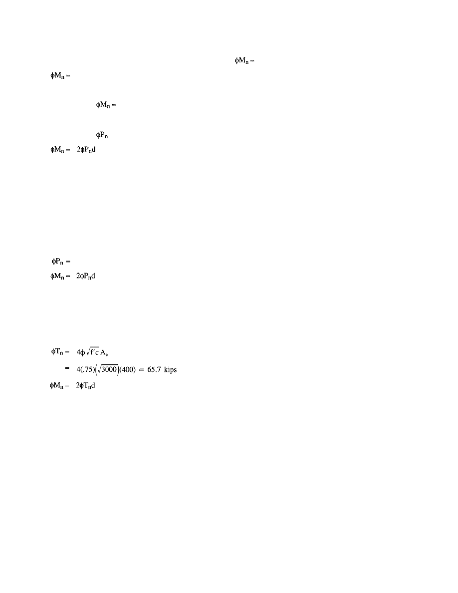
Failure Mode 1: Weld Design Strength
Same as Example 3.
41.7ft.-kips
Failure Mode 2: Base Plate Failure
From Table 3,
26.5 ft.-kips
Failure Mode 3: Rupture of Anchor Rods
From Table 5,
= 14.4 kips
= 2(14.4)(16)
=
461 in.-kips
= 38.4
ft.-kips
Failure Modes: 4 and 5
Same as Example 3.
Failure Mode 6: Anchor Rod Pull Out
From Table 10, for the 3/4 in. anchor rods spaced 16"
o.c. with nutted ends, embedded 12 inches:
82.3 kips/rod
= 2(82.3)(16)
=
2,634 in.-kips
= 219
ft.-kips
Check the design strength based on pier area.
A
e
= 20(20) = 400 in.
2
= 2(65.7)(16) = 2,102 in.-kips
= 175
ft.-kips (controls)
Failure Mode 7: Anchor Rod "push through" (Does not
occur because of pier.)
Failure Mode 8: Pier Bending Resistance
The reinforcement ratio for the 24"x24" pier with 8-#6
bars equals:
8(0.44)(100)/(24)
2
= 0.6%
From Table 18, the bending design strength for the pier
is 147.4 ft.-kips. (Based on a 0.5% reinforcement ratio.)
The development length calculations are the same as in
Example 4-3.
Failure Mode 9: Footing overturning
Same as Example 4-3,
18.9 ft.-kips
Based on the above calculations the overturning resis-
tance equals 18.9 ft.-kips and is controlled by footing
overturning.
Since the controlling failure mode was based on conser-
vative values taken from Table 19, and which do not in-
clude the pier or column weight, a more exact calcula-
tion could be performed as in Example 4-1.
Example 4-5
For the column/footing detail provided in Example 4-1,
determine if a 25 foot and a 40 foot tall column could
safely resist the overturning moment from a 60 mph
wind. Use exposure B conditions.
The reduction factor of 0.75 is not applied to the wind
velocity because this check is for an actual expected ve-
locity.
From Example 4-1, the overturning design strength
equals 8.9 ft.-kips.
Wind Calculations:
F = q
z
G
h
C
f
A
f
where
q
z
= evaluated
at
height
Z
above ground
G
h
= given in ASCE 7 Table 8
C
f
= given
in
ASCE 7 Tables 11-16
A
f
= projected area normal to wind
q
z
- 0.00256K
Z
(IV)
2
K
z
= ASCE
7
Table
6,
Velocity Exposure Coefficient
I
= ASCE 7 Table 5, Importance Factor
V = Basic
wind speed per ASCE 7 para. 6.5.2.
25 foot column calculations:
q
z
= 0.00256(0.46)[(1.0)(60)]
2
= 4.24 psf
F = (4.24)(1.54)(1.5)Af=9.8A
f
psf
A
f
= 12 in. (column
width) = 1.0 ft.
F = 9.8(1.0) = 9.8 psf
F
u
= (1.3)(9.8)
=12.74 psf
M
u
= F
u
h
2
/2 = (12.74)(25)
2
/2 = 3.981 ft.-lbs.
= 3.98
ft.-kips
3.98 < 8.9 o.k.
40 foot column calculations:
23
© 2003 by American Institute of Steel Construction, Inc. All rights reserved.
This publication or any part thereof must not be reproduced in any form without permission of the publisher.
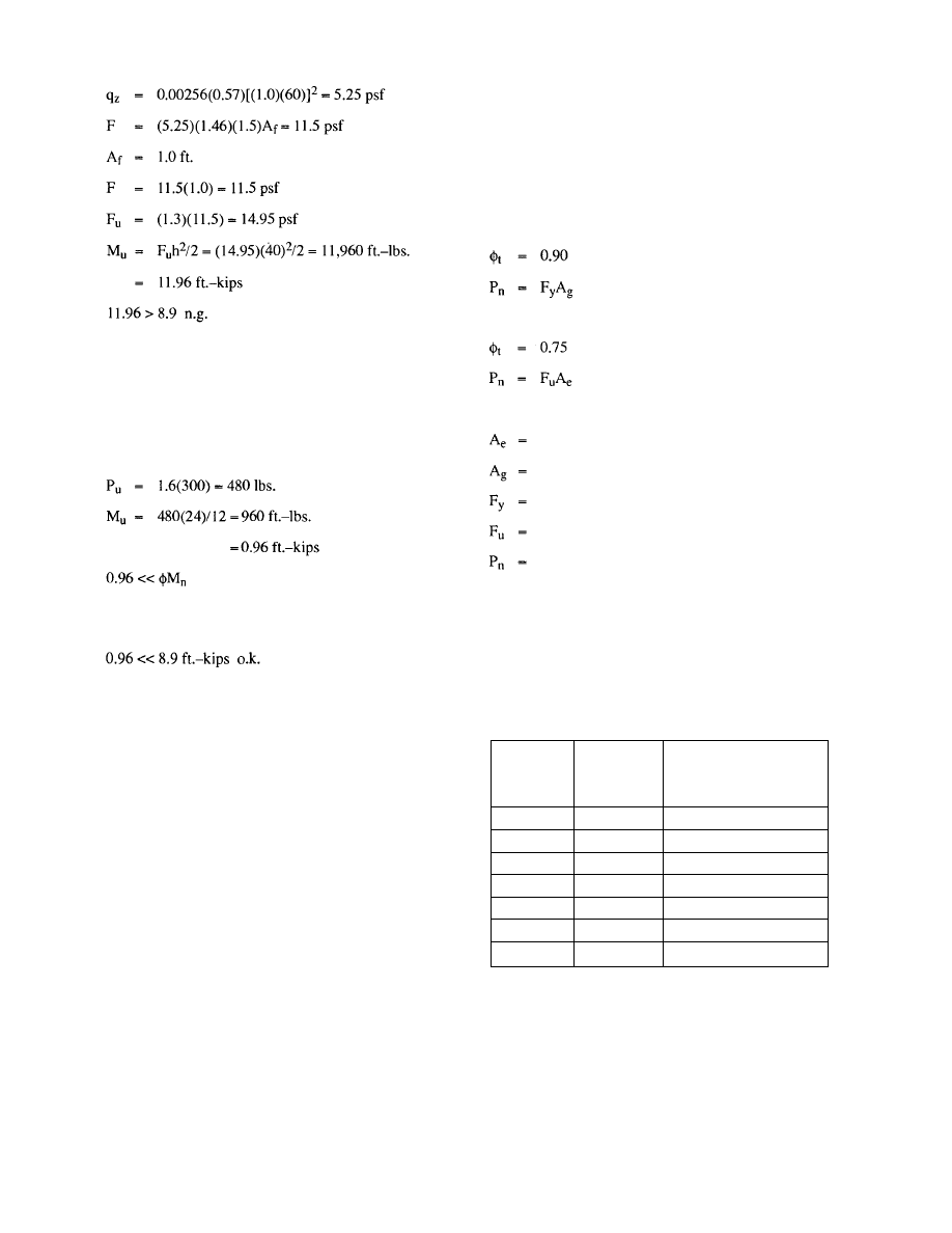
Would the columns described in Example 4-5 safely
support a 300 pound load located 18 inches off of the
column face?
Example 4-6
Factored load:
4.3 Tie Members
During the erection process the members connect-
ing the tops of columns are referred to as tie members.
As the name implies, tie members, tie (connect) the
erected columns together. Tie members can serve to
transfer lateral loads from one bay to the next. Their
function is to transfer loads acting on the partially
erected frame to the vertical bracing in a given bay. Tie
members also transfer erection loads from column to
column during plumbing operations. Typical tie mem-
bers are wide flange beams, steel joists and joist girders.
Since tie members are required to transfer loads,
their design strength must be evaluated. Strength evalu-
ation can be divided into three categories:
A. Tensile Strength
B. Compressive
Strength
C. Connection
Strength
4.3.1 Wide
Flange
Beams
Tensile Design Strength
The tension design strength of any wide flange
beam acting as a tie member will typically not require
detailed evaluation. The design strength in tension will
24
almost always be larger than the strength of the connec-
tion between the tie member and the column. Thus, the
tie member will not control the design of the tie. If the
tensile design strength of a tie member must be deter-
mined, it can be determined as the lesser value of the fol-
lowing:
For yielding in the gross section:
For fracture in the net section:
where
effective net area, in.
2
gross area of member, in.
2
specified minimum yield stress, ksi
specified minimum tensile strength, ksi
nominal axial strength, kips
Compression Design Strength
For compression loading wide flange tie beams can
buckle since they are not laterally supported. Shown in
Table 4.1 are buckling design strengths for the lightest
wide flange shapes for the depths and spans shown in the
Table. These values cannot exceed the connection value
for the type of connection used.
Span
(ft.)
20
25
30
35
40
45
50
Depth
(in.)
14
16
18
21
24
27
30
Compression
Design Strength
(kips)
20
20
25
25
25
60
65
Table 4.1 Wide Flange Design Buckling
Strengths
The compression design strengths for specific wide
flange beams can be determined from the column equa-
tions contained in Chapter E of the AISC Specifications
and the design aids of the LRFD Manual Part 3.
Connection Design Strength
Common connections consist of:
From Example 4-1, the overturning design strength
equals 8.9 ft.-kips.
© 2003 by American Institute of Steel Construction, Inc. All rights reserved.
This publication or any part thereof must not be reproduced in any form without permission of the publisher.
Connection
Type
Beams on Columns
1/4 in. Framing Angles
5/16 in. Framing Angles
3/8 in. Framing Angles
1/4 in. Single-Plate
Shear Connections
3/8 in. Seat
Design
Strength
(kips)
30
10
15
22
30
30
Controlling
Element
Bolts
Framing
Angles
Framing
Angles
Framing
Angles
Bolts
Bolts
Span
(ft.)
20
25
30
35
40
45
50
Joist
Desig-
nation
10K1
14K1
18K3
20K4
20K5
26K5
28K7
Rows of
Bridging
2
2
3
3
4
4
4
Allowable
Load
(kips)
6.0
4.0
4.0
3.5
4.0
4.0
4.0
Span
(ft.)
20
25
30
35
40
45
50
Joist
Desig-
nation
10K1
14K1
18K3
20K4
20K5
26K5
28K7
Rows of
Bridging
2
2
3
3
4
4
4
Design
Strength
(kips)
11.0
7.0
7.0
6.0
7.0
7.0
7.0
1. Beams resting on column tops.
2. Framing
angle connections.
3. Single-Plate
Shear
Connections.
4. Seat
angles.
Presented in Table 4.2 are connection design
strengths for these connections. These strengths are
based on the installation of two 3/4" diameter A325
bolts snug tight in each connection. The controlling ele-
ment is also shown.
(LRFD) are shown in Table 4.3a for several spans with
the joist sizes as shown. Provided in Table 4.3b are the
service load (ASD) values.
Table 4.3a Joist Compression Design Strength
Table 4.3b Joist Compression Allowable Load
Compressive design strengths for other spans and
joist sizes can be obtained from the joist supplier.
Connection Strength
Tie joists are typically connected to column tops us-
ing two ½-inch A307 bolts. Many erectors also weld
the joists to their supports using the Steel Joist Institute's
minimum weld requirements (two
1
/
8
-inch fillet welds
one inch long). Since most joist manufacturers supply
long slotted holes in the joist seats the welding is re-
quired to hold the joists in place. The design shear
strength for the two
1
/
8
-inch fillet welds is 7.4 kips,
based on using E70 electrodes.
It should be remembered that if the connections are
not welded a considerable displacement may occur be-
fore the bolts bear at the end of the slot.
The design shear strength for other weld sizes can
be determined from the AISC LRFD Specification. For
E70 electrodes the design shear strength per inch of
weld length can be calculated by multiplying the fillet
weld size in sixteenths by 1.392.
Table 4.2 WF Connection Strengths
4.3.2 Steel
Joists
Tensile Strength
As for the case of wide flange beams the tensile de-
sign strength for a tie joist will generally not require
evaluation. The connection of the tie joist to the column
is almost always weaker than the tensile design strength
for the joist. If one wants to evaluate the tensile design
strength, it can again be determined from the equation:
It is suggested that only the top chord area be used
for A in the calculation. The area can be determined by
contacting the joist supplier or by physically measuring
the size of the top chord. The yield strength of K and LH
series joists top chords is 50 ksi.
Compressive Strength
Because the compressive design strength of an un-
bridged K-series joist is low, unbridged K-series joists
should not be relied upon to transfer compression forces
from one bay to the next. The unbridged strength is gen-
erally in the 700 to 800 pound range. Once the joists are
bridged they have considerably greater compressive
strength. Approximate compressive design strengths
25
© 2003 by American Institute of Steel Construction, Inc. All rights reserved.
This publication or any part thereof must not be reproduced in any form without permission of the publisher.
4.3.3 Joist
Girders
Tensile Strength
The same comments apply to joist girders as do for
joists acting as tension ties. Connection strengths will
again typically control the design.
Compressive Strength
The design compressive strength of joist girders
can be determined from the AISC LRFD Specification
column equations. Joist girders should be considered as
laterally unbraced until the roof or floor deck has been
secured to the joists. Joists which are not decked may
supply some lateral bracing to the joist girder but the
amount of support cannot be readily determined.
Shown in Table 4.4a are design compressive
strength (LRFD) values for joist girders with the top
chord angles shown. Provided in Table 4.4b are the ser-
vice load (ASD) values. In all cases the minimum avail-
able thicknesses of the angles has been assumed in cal-
culating the values provided in the table.
Connection Strength
Tie joist girders are typically connected to column
tops using two
3
/
4
-inch A325 bolts. The minimum size
SJI welds consist of two ¼-inch fillet welds 2 inches
long. Long slotted holes are generally provided in the
joist girder seats as in the case of joists. The design shear
strength for the two ¼-inch fillet welds is 29.6 kips.
Table 4.4b Joist Girder Service Load
Buckling Strengths (kips)
Example 4-7: (Service Load Design)
This example is done with service loads for easy com-
parison to Example 5-1.
Given: One frame line braced with permanent bracing.
Bays: 6 bays at 40'-0"
Transverse bay: 40'-0" to one side of frame
Have height: 25'-0"
Tie beams: W18X35
Girders: W24X55
Joists: 22K9 @5'-0" o.c.
Columns: W8X31
Permanent bracing: 2(2) < 3 X 3 ½ X ¼ w/(4 )
" dia. A325N Bolts
Permanent brace force: 38 kips
Wind speed: 75 mph
Exposure: B
Determination of wind load:
From ASCE 7 Table 4:
F = q
z
G
h
C
f
A
f
Eq.5-5
where
q
z
= evaluated at height Z above ground
G
h
= given in ASCE 7 Table 8
C
f
= given
in
ASCE 7 Tables 11-16
A
f
= projected
area
normal to wind
q
z
= 0.00256K
Z
(IV)
2
Eq.
3-2
K
z
= ASCE
7
Table 6, Velocity Exposure Coefficient
I =
ASCE
7
Table
5,
Importance Factor
V = Basic wind speed per ASCE 7 para. 6.5.2.
Per the proposed ASCE Standard "V" can be reduced
using the 0.75 factor for an exposure period of less than 6
weeks.
26
Table 4.4a Joist Girder Design Buckling
Strengths (kips)
4.4 Use of Permanent Bracing
The design procedure for temporary bracing can be ap-
plied to permanent bracing used as part of the temporary
bracing scheme. It involves the determination of a de-
sign lateral force (wind, seismic, stability) and con-
firmation of adequate resistance. The design procedure
is illustrated is the following example.
Span
ft.
30
35
40
45
50
55
60
Top
21/2
3
2
2
1
1
-
-
Chord
3
6
4
3
2
2
2
-
Angle
31/2
12
9
7
5
4
4
3
Leg Length, (in.)
4
18
13
10
8
6
5
4
5
43
32
24
19
16
13
11
6
74
55
42
33
27
22
19
Span
ft.
30
35
40
45
50
55
60
Top Chord
2
½
3
1.8 3.5
1.2 2.5
1.2 1.8
0.6 1.2
0.6 1.2
-
1.2
- -
Angle Leg Length, (in.)
3
½
4
7.1
10.6
5.3 7.6
4.1 5.9
2.9 4.7
2.5 3.5
2.5 2.9
1.8 2.5
5 6
25.3 43.5
18.8 32.4
14.1 24.7
11.2 19.4
9.4 15.9
7.6
12.9
6.5
11.2
¾
© 2003 by American Institute of Steel Construction, Inc. All rights reserved.
This publication or any part thereof must not be reproduced in any form without permission of the publisher.
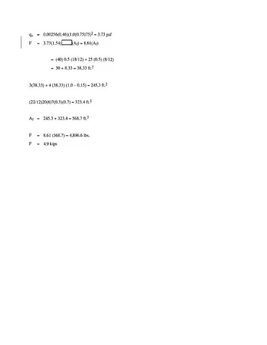
Force in diagonal = 4.9 kips (47.2/40) = 5.8 kips
This force is less than the bracing force of 38 kips for
which the permanent bracing is designed.
One bolt in each angle is adequate to resist the tempo-
rary bracing force in the diagonal. The permanent brac-
ing connections are adequate by inspection.
The roof strut itself is a W24X55 spanning 40 feet. The
strut force is 4.8 kips. Per Tables 4.1 and 4.2, it can be
seen that this member is adequate to carry the strut force.
A check of PA effects is not necessary for permanent di-
agonal bracing used as part of the temporary bracing
scheme.
Lastly, the column on the compression side of the diago-
nally braced bay must be checked.
The column itself is adequate by inspection for the verti-
cal component of the temporary bracing force. This ver-
tical component is 5.8 (25/47.2) = 3.1 kips which is far
less than the column axial capacity.
4.5 Beam to Column Connections
In the typical erection process, the beam to column
connections are erected using only the minimum num-
ber of bolts required by OSHA regulations. This is done
to expedite the process of "raising" the steel in order to
minimize the use of cranes. Final bolting is not done un-
til the structure is plumbed.
In addition to the connection design strength using
the minimum fasteners, additional design strength can
be obtained by installing more fasteners up to the full de-
sign strength. This additional design strength can be in-
corporated in the temporary bracing scheme. Because
of the complexity of integrating final connections in the
temporary supports this topic is not developed in this
guide, however the principles are fully developed in
current literature such as LRFD Manual of Steel
Construction, Volume II (14) and [ASD] Manual of
Steel Construction, "Volume II – Connections" (13).
4.6 Diaphragms
Roof or floor deck can be used during the erection
process to transfer loads horizontally to vertical bracing
locations. The ability of the deck system to transfer
loads is dependent on the number and type of attach-
ments made to the supporting structure and the type and
frequency of the deck sidelap connections. Because of
the number of variables that can occur with deck dia-
phragms in practice, no general guidelines are presented
here. The designer of the temporary bracing system is
simply cautioned not to use a partially completed dia-
phragm system for load transfer until a complete analy-
sis is made relative to the partially completed dia-
phragm strength and stiffness. Evaluation of diaphragm
strength can be performed using the methods presented
in the Steel Deck Institute's "Diaphragm Design Manu-
al" (8).
5. RESISTANCE TO DESIGN LOADS —
TEMPORARY SUPPORTS
The purpose of the temporary support system is to
adequately transfer loads to the ground from their
source in the frame. Temporary support systems trans-
fer lateral loads (erection forces and wind loads) to the
ground. The principal mechanism used to do this is tem-
porary diagonal bracing, such as cables or struts, the use
of the permanent bracing or a combination thereof.
Temporary diagonal struts which carry both tension and
compression or just compression are rarely used. Cable
braces are often used. In cases when the building is
framed with multiple bays in each direction, dia-
phragms are used in the completed construction to trans-
fer lateral loads to rigid frames or braced bays. Before
the diaphragm is installed temporary supports are re-
quired in the frame lines between the frames with per-
manent bracing.
The use of cables to provide temporary lateral brac-
ing in a frame line requires that the following conditions
be met:
1. Functional strut elements (beams, joists, girders) to
transfer the lateral load to the cable braced bay.
2. Functional
transfer
of
the
lateral load into the brac-
ing tension cable and compression column pair.
3. Functional
resistance of the anchorage of the cable
and the column to their respective bases and to the
ground.
27
Calculating:
The area of the frame (A
f
) is computed as follows:
First frame
Thus the total frame area is:
The net area of joists is computed as:
Thus,
F at the level of the roof strut is:
Rev.
3/1/03
© 2003 by American Institute of Steel Construction, Inc. All rights reserved.
This publication or any part thereof must not be reproduced in any form without permission of the publisher.
(1.5)
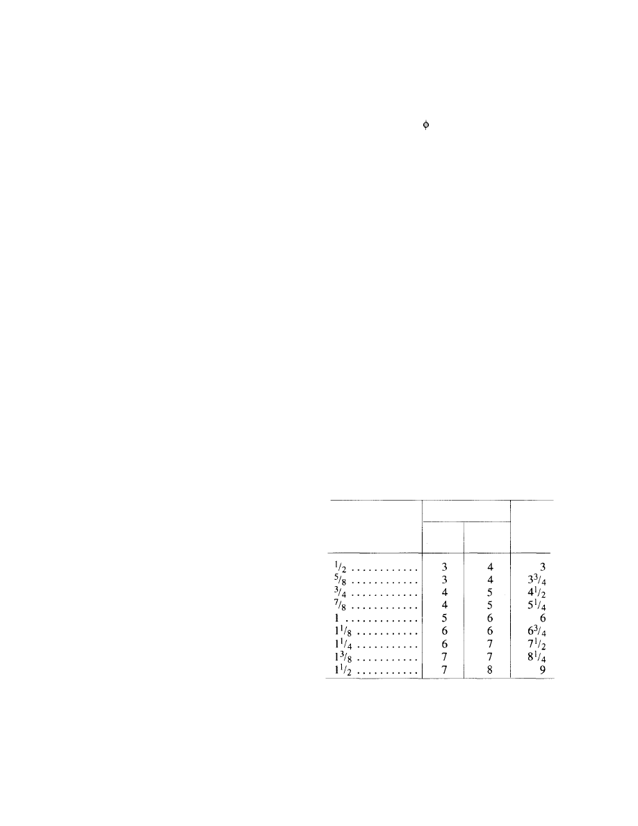
The development of the beams or joists as function-
al strut elements requires a check of their design
strength as unbraced compression elements, since their
stabilizing element, the deck, will not likely be present
when the strength of the struts is required. The strut con-
nections must also be checked since the connections
will likely only be minimally bolted at the initial stage
of loading. The evaluation of strut members is dis-
cussed in detail elsewhere in this Design Guide.
The development of the cable is accomplished by
its attachment to the top of the compression column and
to the point of anchorage at the bottom end. In multi-
tier construction the bottom end would be attached to
the adjacent column. In the lowest story of a multi story
frame or a one story frame, the lower end of the cable
would be attached to the base of the adjacent column or
to the foundation itself.
5.1 Wire Rope Diagonal Bracing
Bracing cables are composed of wire rope and an-
chorage accessories. Wire rope consists of three compo-
nents: (a) individual wires forming strands, (b) a core
and (c) multi-wire strands laid helically around the
core. The wires which form the strands are available in
grades, such as "plow steel", "improved plow steel" and
"extra improved plow steel". Cores are made of fiber,
synthetic material, wire or a strand. The core provides
little of the rope strength but rather forms the center
about which the strands are "laid". Laying is done in
four patterns: regular, left and right and Lang, left and
right. The left and right refer to counter-clockwise and
clockwise laying. Regular lay has the wires in the
strands laid opposite to the lay of the strands. Lang lay
has the wires in the strands laid in the same direction as
the lay of the strands. Most wire rope is right lay, regular
lay. Wire rope is designated by the number of strands,
the number of wires per strands, the strand pattern
(construction), the type of core, type of steel and the
wire finish. The diameter of a wire rope is taken at its
greatest diameter. The wire rope classification is desig-
nated by the number of strands and by the number of
wires per strand.
The strength of wire rope is established by the indi-
vidual manufacturers who publish tables of "Nominal
Breaking Strength" for the rope designation and diame-
ter produced. The safe working load for wire rope is es-
tablished by dividing the Normal Breaking Strength by
a factor of safety. This factor of safety ranges between 6
and 2 depending on how the wire rope is used. The in-
formation presented on wire rope in this guide is taken
from two references: the "Wire Rope Users Manual"
published by the Wire Rope Technical Board (19) and
the "Falsework Manual" published by the State of
California Department of Transportation (Caltrans) (9).
The Wire Rope Technical Board does not set a factor of
safety for wire rope used as temporary lateral supports.
However, the Users Manual does state that "a 'common'
design factor is 5". This design factor is used for slings
and other rigging, but it is unnecessarily conservative
for the diagonal bracing covered in this guide. The au-
thors recommend the use of a factor of safety of 3 for
ASD and the use of = 0.5 for LRFD. The Caltrans
Falsework Manual uses a factor of safety of 2.0 but it ap-
plies to the breaking strength reduced by a connection
efficiency factor. Caltrans assigns the following con-
nection efficiencies:
Sockets-Zinc Type
100%
Wedge Sockets
70%
Clips-Crosby Type 80%
Knot and Clip (Contractor's Knot) 50%
Plate Clamp-Three Bolt Type 80%
Spliced eye and thimble
3/8 inch to 3/4 inch
95%
7/8 inch to 1 inch
88%
Wire rope connections using U-bolt clips (Crosby
type) are formed by doubling the rope back upon itself
and securing the loose or "dead" end with a two part clip
consisting off a U-bolt and a forged clip. Table 5.1 is
taken from OSHA 1926.251. It gives the minimum
number and spacing of clips for various wire sizes. The
spacing is generally six times the wire diameter. Clip
manufacturers give minimum installation torques for
the nuts in their literature. When installing the clips, the
U-bolt is set on the dead (loose) end. The clip is placed
against the live (loaded) side. "Never saddle a dead
horse," as the saying goes.
OSHA CFA 1926.251
TABLE H-20 - NUMBER AND SPACING
OF U-BOLT WIRE ROPE CLIPS
Table 5.1
U-Bolt Wire Rope Clips
The use of wire rope (cables) in diagonal temporary
bracing also requires an assessment of the stiffness of
the braced panel which is primarily a function of the
elongation of the cable under load. This elongation has
two sources: elastic stretch (roughly (PL)/(AE)) and
constructional stretch, which is caused by the strands
28
Improved plow
steel, rope diameter
(inches)
Number of clips Minimum
spacing
(inches)
Drop
forged
Other
material
© 2003 by American Institute of Steel Construction, Inc. All rights reserved.
This publication or any part thereof must not be reproduced in any form without permission of the publisher.
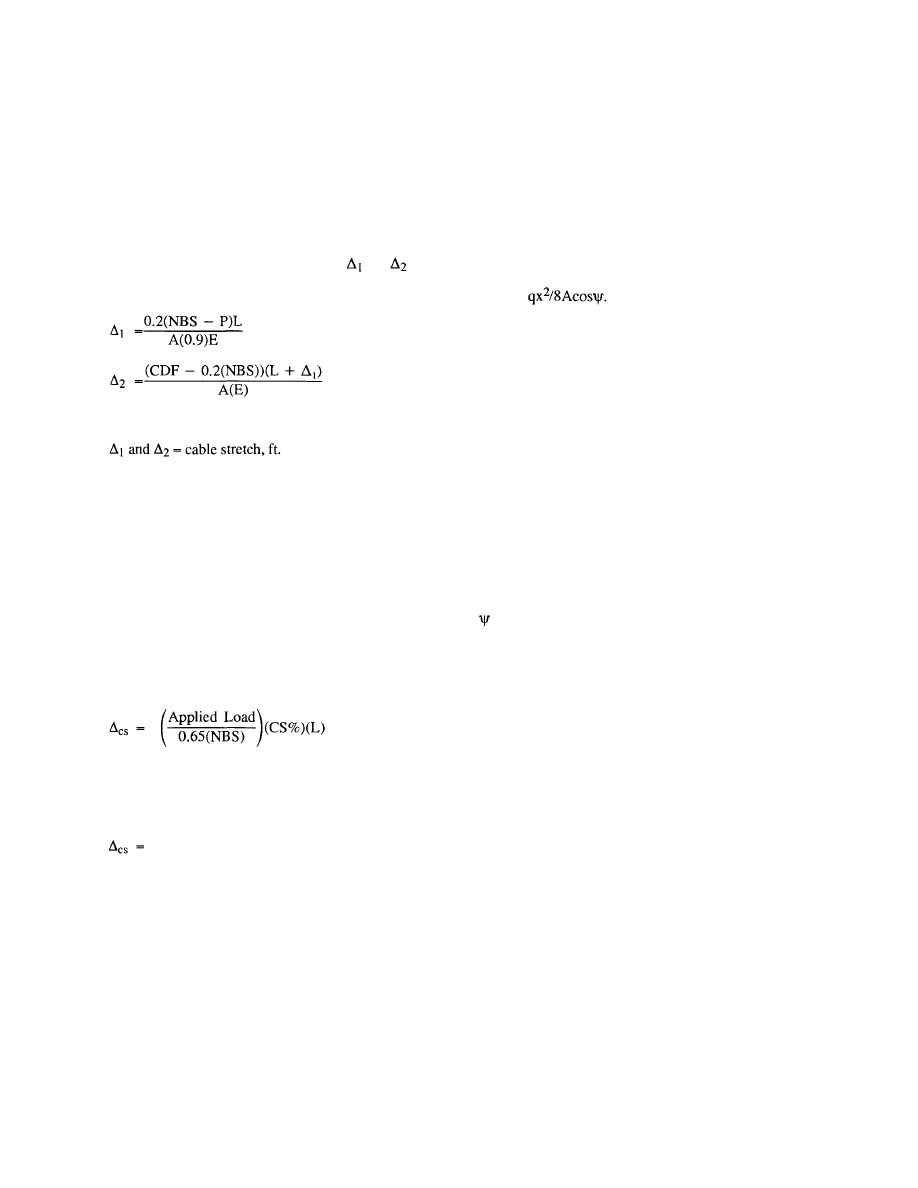
compacting against one another under load. Wire rope
can be pre-stretched to remove some constructional
elongation.
Elastic stretch in cable is not a linear function as
with true elastic materials. The modulus of elasticity
(E) for wire rope varies with load. When the load is less
than or equal to 20 percent of the breaking strength a re-
duced E equal to 0.9E is used in industry practice. When
the cable load exceeds 20 percent of the breaking
strength the elastic stretch is the sum of
and
as de-
fined below.
The cable drape (A) is a vertical distance measured
at mid-bay between the two cable end points.
Drawing up the cable to the maximum allowed
drape induces a force in the cable which can be calcu-
lated from the following equation presented in the
Falsework Manual.
P =
Eq.5-4
where
P = cable
preload
value, lbs.
q = cable
weight, pounds per ft.
x = horizontal
distance between connection points,
ft.
A = cable drape, ft.
= angle
between horizontal and cable (if straight),
degrees
The Caltrans Falsework Manual also recommends
a minimum preload of 500 pounds.
It should be noted that the installers should be cau-
tioned not to overdraw the cable as this may pull the
frame out of plumb or may overload components of the
frame.
The following eight tables (Tables 5.2 through 5.8)
present wire rope data taken from the "Wire Rope Users
Manual" for various classifications, core types and steel
grades. The values for weight and metallic area are la-
beled approximate since the actual values are different
for each manufacturer. The value given for area is that
appropriate to the particular construction identified (S,
Seale; FW, Filler Wire; W, Warington). The Nominal
Breaking Strength given is the industry consensus val-
ue. Galvanized wire is rated at 10 percent less than the
values given for Bright (uncoated) wire. Data for a spe-
cific wire rope (diameter, classification, construction,
core and steel) should be obtained from the manufactur-
er.
29
where
CS% is the constructional stretch percentage supplied
by the manufacturer (usually between 0.75% and 1.0%).
constructional stretch, ft.
L = cable
length, ft.
The load and cable strength are in pounds.
In order for wire rope cables to perform properly it
is necessary to provide an initial preload by drawing
them up to a maximum initial drape. The Caltrans
Falsework Manual provides the following maximum
drapes for these cable sizes:
Cable Size
Maximum Drape (A)
3/8 1
inches
1/2 2
inches
3/4 2-3/4
inches
Eq. 5-3
NBS = Nominal Breaking Strength, lbs.
P = Cable
Preload,
lbs.
CDF = Cable Design Force, lbs.
L = cable
length, ft.
A = net
metallic
area
of
cable, in.
2
E = nominal
modulus of elasticity, psi
Constructional stretch is given by the following formu-
la:
where
Eq. 5-1
Eq.5-2
© 2003 by American Institute of Steel Construction, Inc. All rights reserved.
This publication or any part thereof must not be reproduced in any form without permission of the publisher.
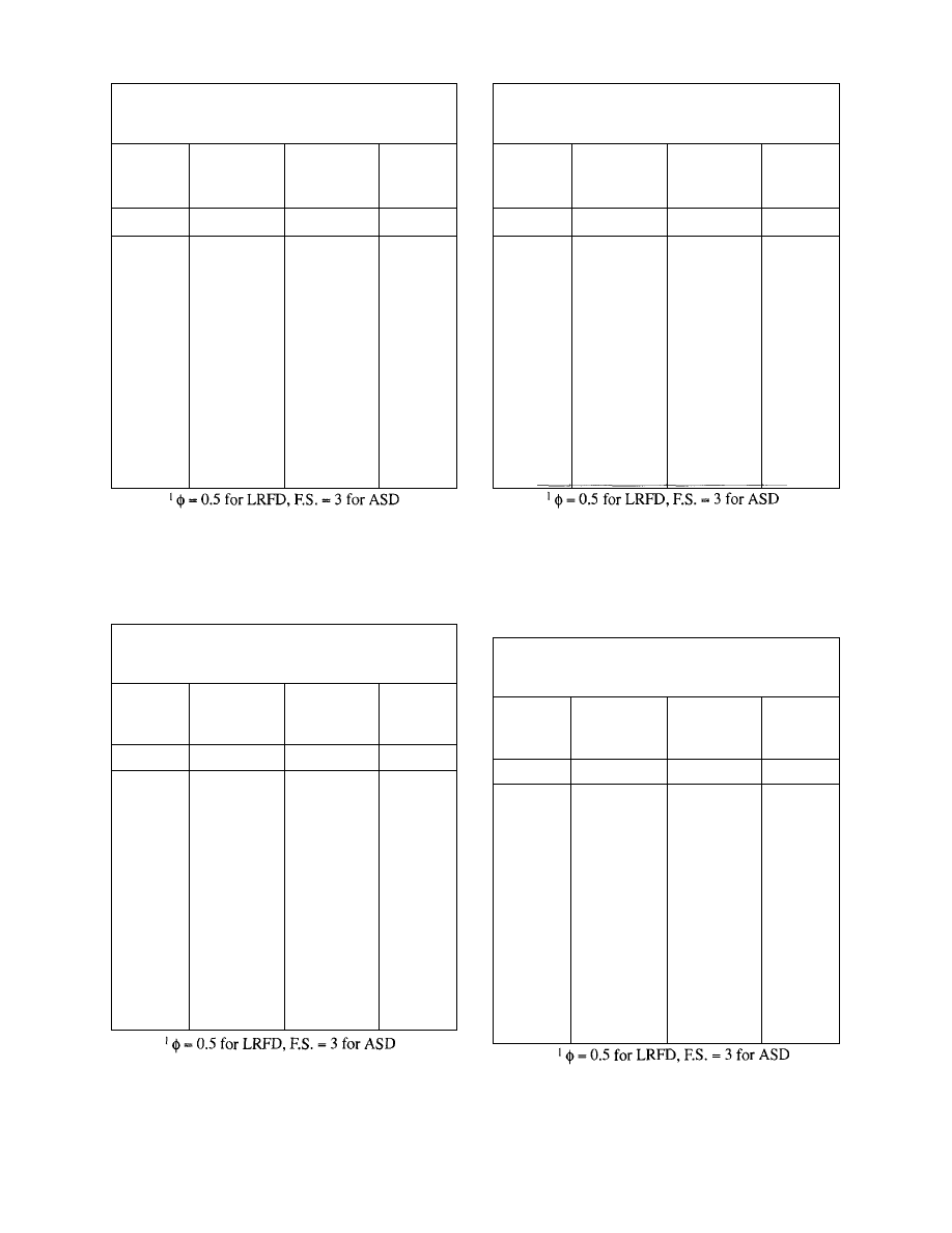
6x19 (S) Classification/Bright (Uncoated),
Fiber Core, Improved Plow Steel,
E = 12,000,000 psi
Nominal
Diameter
inches
3/8
7/16
1/2
9/16
5/8
3/4
7/8
1
Approximate
Weight
lbs./ft.
0.24
0.32
0.42
0.53
0.66
0.95
1.29
1.68
Approximate
Metallic
Area
in.
2
0.057
0.077
0.101
0.128
0.158
0.227
0.354
0.404
Nominal
Breaking
Strength
1
lbs.
12,200
16,540
21,400
27,000
33,400
47,600
64,400
83,600
8x19 (W) Classification/Bright (Uncoated),
Fiber Core, Improved Plow Steel,
E = 9,000,000 psi
Nominal
Diameter
inches
3/8
7/16
1/2
9/16
5/8
3/4
7/8
1
Approximate
Weight
lbs./ft.
0.22
0.30
0.39
0.50
0.61
0.88
1.20
1.57
Approximate
Metallic
Area
in.
2
0.051
0.070
0.092
0.116
0.143
0.206
0.280
0.366
Nominal
Breaking
Strength
1
lbs.
10,480
14,180
18,460
23,200
28,600
41,000
55,400
72,000
6x7 Classification/Bright (Uncoated),
Fiber Core, Improved Plow Steel,
E = 13,000,000 psi
Nominal
Diameter
inches
3/8
7/16
1/2
9/16
5/8
3/4
7/8
1
Approximate
Weight
lbs/ft.
0.21
0.29
0.38
0.48
0.59
0.84
1.15
1.50
Approximate
Metallic
Area
in.
2
0.054
0.074
0.096
0.122
0.150
0.216
0.294
0.384
Nominal
Breaking
Strength
1
lbs.
11,720
15,860
20,600
26,000
31,800
45,400
61,400
79,400
6x37 (FW) Classification/Bright (Uncoated),
Fiber Core, Improved Plow Steel,
E = 11,000,000 psi
Nominal
Diameter
inches
3/8
7/16
1/2
9/16
5/8
3/4
7/8
1
Approximate
Weight
lbs./ft.
0.24
0.32
0.42
0.53
0.66
0.95
1.29
1.68
Approximate
Metallic
Area
in.
2
0.060
0.082
0.107
0.135
0.167
0.240
0.327
0.427
Nominal
Breaking
Strength
1
lbs.
12,200
16,540
21,400
27,000
33,400
47,600
64,400
83,600
Table 5.2 Nominal Breaking Strength
of Wire Rope
Table 5.4 Nominal Breaking Strength
of Wire Rope
Table 5.3
Nominal Breaking Strength
of Wire Rope
Table 5.5
Nominal Breaking Strength
of Wire Rope
30
© 2003 by American Institute of Steel Construction, Inc. All rights reserved.
This publication or any part thereof must not be reproduced in any form without permission of the publisher.
6x19 (S) Classification/Bright (Uncoated),
IWRC, Improved Plow Steel,
E = 15,000,000 psi
Nominal
Diameter
inches
3/8
7/16
1/2
9/16
5/8
3/4
7/8
1
Approximate
Weight
lbs./ft.
0.26
0.35
0.46
0.59
0.72
1.04
1.42
1.85
Approximate
Metallic
Area
in.
2
0.066
0.090
0.118
0.149
0.184
0.264
0.360
0.470
Nominal
Breaking
Strength
1
lbs.
13,120
17,780
23,000
29,000
35,400
51,200
69,200
89,800
6x37 (FW) Classification/Bright (Uncoated),
IWRC, Improved Plow Steel,
E = 14,000,000 psi
Nominal
Diameter
inches
3/8
7/16
1/2
9/16
5/8
3/4
7/8
1
Approximate
Weight
lbs./ft.
0.26
0.35
0.46
0.59
0.72
1.04
1.42
1.85
Approximate
Metallic
Area
in.
2
0.069
0.094
0.123
0.156
0.193
0.277
0.377
0.493
Nominal
Breaking
Strength
1
lbs.
13,120
17,780
23,000
29,000
35,400
51,200
69,200
89,800
Table 5.6 Nominal Breaking Strength
of Wire Rope
Table 5.8 Nominal Breaking Strength
of Wire Rope
6x19 (S) Classification/Bright (Uncoated),
IWRC, Extra Improved Plow Steel,
E = 15,000,000 psi
Nominal
Diameter
inches
3/8
7/16
1/2
9/16
5/8
3/4
7/8
1
Approximate
Weight
lbs./ft.
0.26
0.35
0.46
0.59
0.72
1.04
1.42
1.85
Approximate
Metallic
Area
in.
2
0.066
0.090
0.118
0.149
0.184
0.264
0.360
0.470
Nominal
Breaking
Strength
1
lbs.
15,100
20,400
26,600
33,600
41,200
58,800
79,600
103,400
6x37 (FW) Classification/Bright (Uncoated),
IWRC, Extra Improved Plow Steel,
E = 14,000,000 psi
Nominal
Diameter
inches
3/8
7/16
1/2
9/16
5/8
3/4
7/8
1
Approximate
Weight
lbs./ft.
0.26
0.35
0.46
0.59
0.72
1.04
1.42
1.85
Approximate
Metallic
Area
in.
2
0.069
0.094
0.123
0.156
0.193
0.277
0.377
0.493
Nominal
Breaking
Strength
1
lbs.
15,100
20,400
26,600
33,600
41,200
58,800
79,600
103,400
Table 5.7 Nominal Breaking Strength
of Wire Rope
Table 5.9 Nominal Breaking Strength
of Wire Rope
31
© 2003 by American Institute of Steel Construction, Inc. All rights reserved.
This publication or any part thereof must not be reproduced in any form without permission of the publisher.

Because of the relative flexibility of wire rope due
to its construction, forces can be induced in the bracing
due to the frame's initial lateral displacement. This se-
cond order effect is commonly referred to as a PA effect.
In the case of a cable diagonal in a braced bay the brac-
ing must resist gravity load instability such as might be
induced by out of plumb columns and more importantly
must resist the induced forces when the upper end of the
column is displaced by a lateral force (wind) to a posi-
tion that is not aligned over the column base.
Gravity load stability is usually addressed with a
strength design of the bracing for an appropriate equiva-
lent lateral static force, commonly 2 percent of the sup-
ported gravity load. Other sources have recommended
that a 100 pound per foot lateral load be applied to the
perimeter of the structure to be braced. This stability
check would not normally govern the design of tempo-
rary bracing.
The forces induced by lateral load displacements
are more significant however. Since each increment of
load induces a corresponding increment of displace-
ment, the design of a diagonal cable brace would
theoretically require an analysis to demonstrate that the
incremental process closes and that the system is stable.
If the incremental load/displacement relationship does
not converge, the system is unstable. In general, the
cables braces within the scope of this guide would con-
verge and one cycle of load/displacement would ac-
count for 90% of the PA induced force. In the example
which follows, the induced force is approximately 20%
of the initial wind induced force. Using a factor of safety
of 3, a design which resists the induced wind force plus
one cycle of PA load-displacement should be deemed
adequate.
The design procedure for the design of temporary
diagonal cable bracing is illustrated in the following ex-
ample.
Example 5-1: (Service Load Design)
Given: One
frame line braced with cables.
Bays: 6 bays of 40'-0"
Transverse bays: 40'-0" each side of frame
Have height: 25'-Q"
Tie beams: W18X35
Girders: W24X68
Joists: 22K9 @ 5'-0" o.c.
Columns: W8X40
Wind speed: 75 mph
Exposure: B
Seismic coefficients: A
a
= 0.10, A
v
= 0.10
Wind pressure and seismic base shear per ASCE 7-93
and Proposed ASCE Standard "Design Loads on Struc-
tures During Construction."
Determination of wind load:
From ASCE 7 Table 4:
F = q
z
G
h
C
f
A
f
(Eq.5-5)
where
q
z
= evaluated
at
height Z above ground
G
h
= given in ASCE 7 Table 8
C
f
= given in ASCE 7 Tables 11-16
A
f
= projected
area
normal to wind
q
z
= 0.00256K
Z
(IV)
2
(Eq.
3-2)
K
z
= ASCE
7 Table 6, Velocity Exposure Coefficient
I
= ASCE 7 Table 5, Importance Factor
V = Basic
wind speed per ASCE 7 para. 6.5.2.
Per the proposed ASCE Standard V can be reduced us-
ing the 0.75 factor for an exposure period of less than 6
weeks.
Calculating:
q
z
= 0.00256(0.46)[1.0(0.75)75]
2
= 3.73 psf
F = 3.73(1.54)(1.5)(Af)
=
8.61(A
f
)lbs.
Determination of Af:
The frame in this example has the following surface area
to the wind. There are seven transverse bays. The frame
area for the first frame is equal to the tributary beam area
plus the tributary column area.
First frame: 2(40)(0.5)(18/12) + 25(0.5)(8/12)
= 60.0 + 8.33 = 68.33 sq. ft.
The second through seventh frame have the same area.
The total frame area, including the 0.15 reduction is
thus:
= 3(68.33)+
4(68.33)(1.0-0.15)
= 437.3
sq.ft.
The net effective area of the joists can be computed as
follows. There are seven joists per bay in six bays. The
gross area is:
(22/12)x40x7x6 = 3080 sq. ft.
The effective solid area would be gross projected area
times 0.3 for net area. The
shielding reduction is
where
n
= 7x6 = 42
Thus the total effective area of the joists is:
32
© 2003 by American Institute of Steel Construction, Inc. All rights reserved.
This publication or any part thereof must not be reproduced in any form without permission of the publisher.
3080x0.3x0.7 = 647.8 sq. ft.
The total frame area, A
f
, is
A
f
= 437.3+
646.8 =1084 sq.ft.
F at the level of the roof struts is:
F = 8.61(1084)
=
9333 lbs.
Determination of stability loading:
"Design Loads on Structures During Construction",
proposed ASCE Standard would require a 100 pound
per foot along the 40 foot perimeter or 2 percent of the
total dead load applied horizontally along the structure
edge.
Total vertical supported dead load:
7 columns: 7(40)25 =
7,000 lbs.
7 beams: 7(35)40
- 9,800 lbs.
6 girders: 6 X (68)40 =
16,320 lbs.
Roof framing*: 6(40)40(5) = 48.000 lbs.
Total
81,120 lbs.
*Joists and bundled deck.
In this example the two stability design values would be:
(100)(40) = 4000 lbs.
or
(81,120)(0.02)=1622 lbs.
In this example neither of these forces would govern as
both are less than the wind design force of 9,333 lbs.
Determination of seismic base shear:
V = C
S
W
(Eq . 3-5)
Determine C
s
(Eq. 3-7)
where
A
a
= 0.10 (ASCE 7 Figure 9.1 (Building located in
Kansas City))
R = 5.0
(ASCE 7 Table 9.3-2)
Determine W
W = 81,120
lbs.
per
calculation above.
V = 0.050
(81,120) = 4056 lbs.
Seismic loading does not govern the design.
Design of diagonal cable:
The geometry of the cable for the purposes of this cal-
culation is:
25 feet vertical (column height)
40 feet horizontal (bay width)
Using the Pythagorean theorem, the diagonal length (L)
is 47.2 feet.
The strut force at the brace = 9333 lbs.
The column force component =9333(25/40)=5833 lbs.
The diagonal cable force = 9333 (47.2/40) = 11,013 lbs.
Using a factor of safety of 3.0, the minimum nominal
breaking strength required is:
(11,013)(3) =33,039 lbs.
Based on Table 5.2 data a 3/4 inch diameter wire rope
has the following properties:
Designation: 6x7 FC-IPS
(Fibercore - improved plow steel)
Area: 0.216, in.
2
Wt. per foot: 0.84 lbs. per ft.
Modulus of elasticity: 13,000 ksi (nominal)
CS% = 0.75%
Nominal breaking strength = 45,400 lbs.
Calculation of cable pre-loading to remove drape:
Per Caltrans the maximum cable drape (A) should be
2.375 inches.
The preload required for this maximum drape (A) is
P =
(Eq
.
5-4)
In this example, cosy - (40/47.2) = 0.847
q =
0.84
lbs.
per
foot, cable weight
x = 40
feet,
horizontal
distance
between
cable con-
nections points
p = (0.84)
(40)
2
/8 (2.375/12) (0.847)
= 1002 lbs.
The horizontal and vertical components of the preload
force are 849 pounds and 531 pounds respectively.
Calculation of elastic and constructional stretch:
Elastic stretch:
20% of breaking strength is
0.2(45,400) = 9080 lbs.
which is less than the cable design force.
33
© 2003 by American Institute of Steel Construction, Inc. All rights reserved.
This publication or any part thereof must not be reproduced in any form without permission of the publisher.
Constructional Stretch:
(Eq. 5-3)
Total elongation = 0.18 + 0.13 = 0.31 ft.
Top of column movement:
b' = 47.2
+
0.31
=
47.51ft.
From the law of cosines:
Determine lateral movement of column top:
Determination of force induced by PA:
P = 81,120
lbs.
as determined previously.
Cable force including
effects:
11,013+ 62=11,075 lbs.
Cable force: 11,075 lbs.
Allowable cable force = 45,400/3 = 15,133 > 11,075 lbs.
Therefore, use a 3/4" diameter cable.
5.2 Wire Rope Connections
Wire rope connections can be made in a variety of ways.
If a projecting plate with a hole in it is provided, then a
Spelter Socket, Wedge Socket or Clevis End fitting can
be used. Cables are also secured to columns by wrap-
ping the column, either with a section of wire rope to
which a hook end turnbuckle is attached or with the end
of the diagonal cable itself which is secured by cable
clamps. If cables are wrapped around an element, such
as a column, a positive mechanism should be provided
to prevent the cable from slipping along the column or
beam. Also when cables are terminated by wrapping,
care should be taken to avoid damage to the wire rope by
kinking or crushing. Cables can also be terminated at
the column base by attachment to a plate or angle at-
tached to the anchor rods above the base plate. The plate
or angle must be designed for the eccentric force in-
duced by the diagonal cable force. Cables are tensioned
and adjusted by the use of turnbuckles which can have a
variety of ends (round eye, oval eye, hook and jaw). The
capacities of turnbuckles and clevises are provided in
manufacturer's literature and the AISC Manual of Steel
Construction. Cable and rope pullers (come-a-longs)
are also used.
5.2.7 Projecting
Plate
(Type
A)
The design of a projecting plate from the face of a col-
umn is illustrated in the following example. Design
strengths for various conditions of cable size, type and
angle of cable can be determined from the accompany-
ing tables. The location of the hole can be set at the up-
per corner. This would allow a reuse after the plate had
been flame cut from a column.
Example 5-2
Design a projecting plate attachment (Type A) for the
cable force determined in Design Example 5-1.
34
© 2003 by American Institute of Steel Construction, Inc. All rights reserved.
This publication or any part thereof must not be reproduced in any form without permission of the publisher.
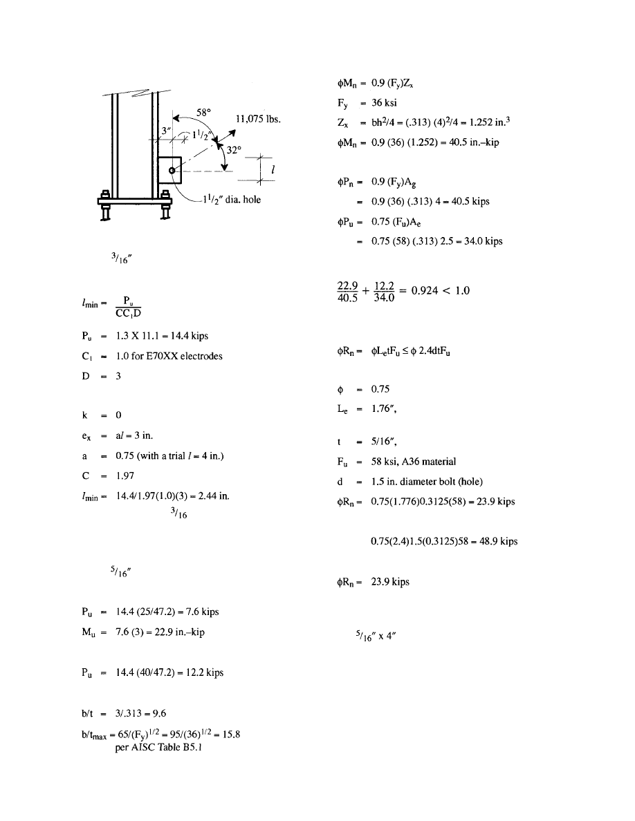
Design of weld to column:
Flexure in plate:
Fig. 5.2.1
Tension in plate:
Checking interaction:
Using
weld fillets along each side of the wing
plate, calculate l
min
per LRFD, 2
nd
ed. Table 8.38.
C is taken from Table 8.38 with:
Check bearing strength at hole per J3.10 of the Specifi-
cation.
Use 4 inches for l and
in. x 4 in. fillet welds each side
of plate.
but not greater than
Design of plate:
Check plate.
Component bending the plate (vertical)
Thus
which is greater than the factored cable force of 14.4
kips
Component tensioning the plate (horizontal)
Check plate b/t (local buckling):
Plate is fully effective
35
The plate and weld can also be found in Table 22 for
the cable type and geometry given.
5.2.2 Bent
Attachment
Plate (Type
B)
Another means of attachment of the diagonal cable to
the column base is a bent plate on one of the column an-
chor rods as illustrated in Figure 5.2.2.
The use of this plate requires extra anchor rod length to
accommodate it. If the plates are to be left in place, they
Use plate.
where
distance from hole centerline to plate
edge
thickness of plate
© 2003 by American Institute of Steel Construction, Inc. All rights reserved.
This publication or any part thereof must not be reproduced in any form without permission of the publisher.
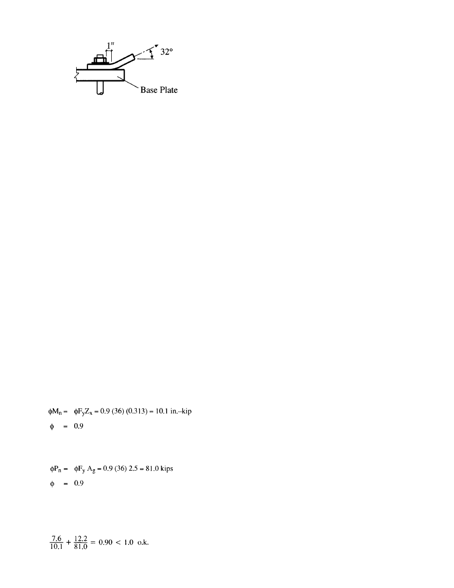
Fig. 5.2.2
must either be in a buried condition or approval must be
obtained if exposed. If the plates are to be removed, the
nut should not be loosened until this can be safely done,
such as when the column and frame are made stable by
other means than full development of all the anchor
rods.
The design of a bent attachment plate (Type B) for cable
attachment is illustrated in the following example. De-
sign strength for various conditions of cable size, type
and angle of cable can be read from the accompanying
tables.
Example 5-3
Design a bent plate attachment (Type B) for the cable
force determined in Design Example 5-1.
Design of bent plate:
Cable force: 11.1 kips at 32° from the horizontal.
As before the force bending the plate is P
u
= 7.6 kips
(vertical) and the force tensioning the plate is P
U
= 12.2
kips.
M
u
= 7.6 (e) = 7.6(1) = 7.6 in.-kip
where
e
= the distance from the bend to the face of the nut
Check a ½ inch thick plate, 5 inches wide
F
y
= 36
ksi
Z
x
= (0.5)
2
5/4 = .313 in.
3
Fy = 36
ksi
A
g
= 0.5 (5) = 2.5 in.
2
Combining flexure and tension:
The strength of the plate at the anchor rod hole and cable
attachment hole can be determined as in the previous ex-
ample.
Use plate ½" x 5".
The attachment plate can also be found in Table 24 for
the cable type and geometry given.
5.2.3 Anchor
Rods
The development of the cable force requires that the an-
chor rods be adequate to transfer the brace force into the
footing and also that the footing be adequate to resist the
brace force acting as a deadman. The adequacy of the
anchor rods in tension is discussed in Part 4 of this
Guide. The anchor rods are also subjected to shear load-
ing. If the base plates are set on pregrouted leveling
plates or are grouted when the cable force is applied then
the procedures presented in AISC Design Guide 7 "In-
dustrial Buildings" can be used. This method is a shear
friction method in which a anchor rod tension is induced
by the shear. If leveling nuts (or shims) are used and
there is no grout at the time of cable force application,
then another procedure must be used. Such a procedure
is found in the 1994 edition of the Uniform Building
Code (17), in Section 1925. This procedure is an ulti-
mate strength design approach and checks both the an-
chor rod and the concrete failure modes. The formulas
of this method are given in the design example which
follows. When leveling nuts (or shims) are used the an-
chor rods are also subject to bending. In the design ex-
ample a check for anchor rod bending is made. The cal-
culation takes as the moment arm, one half of the anchor
rod height since the base of the anchor rod is embedded
in concrete and the top of the anchor rod has nuts above
and below the base plate.
Design Example 5-4 illustrates the procedure for eva-
luating the strength of anchor rods with leveling nuts.
Example 5-4
Check the column anchor rods for the forces induced by
the diagonal cable force determined in Design Example
5-1, using a Type A anchor.
Determine the design strength of four-1 inch diameter
anchor rods with leveling nuts for resistance to the cable
diagonal force.
Grout thickness: 3 in.
Cable diagonal force: 11.1 kips
Vertical component: 11.1 (25/47.2) = 5.9 kips
Horizontal component: 11.1 (40/47.2) = 9.4 kips
Determine net axial load on column:
As determined previously the weight of the frame tribu-
tary to one interior column is:
36
© 2003 by American Institute of Steel Construction, Inc. All rights reserved.
This publication or any part thereof must not be reproduced in any form without permission of the publisher.
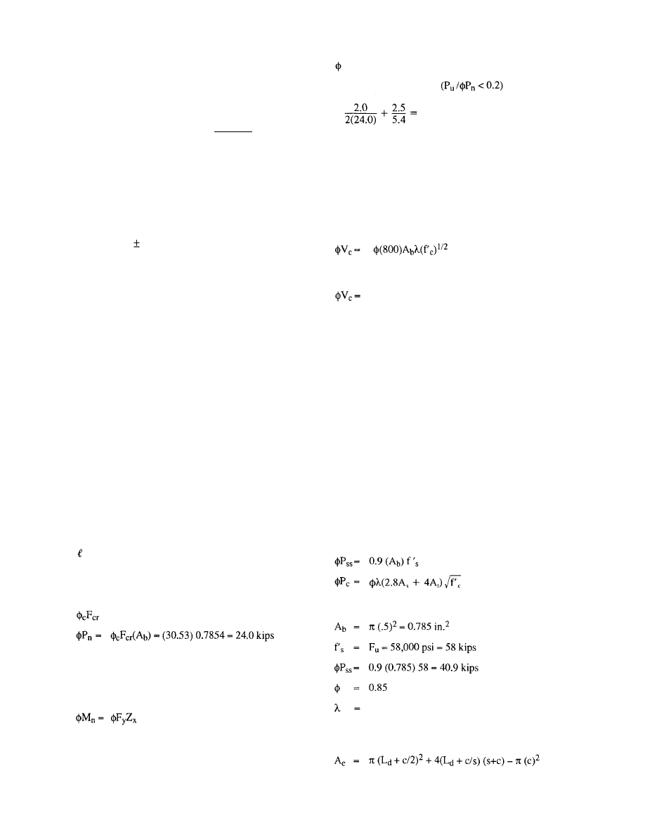
Column: 1(40)25
= 1,000 lbs.
Beams: 2(35)40(0.5)
= 1,400 lbs.
Girders: 2(68)40(0.5) =
2,720 lbs.
Roof framing (40)40(5) = 8.000 lbs.
Total =
13,120
lbs. = 13.1 kips
Gravity load: 13.1 kips lbs.
Wind vertical component: 5.9 kips
Net compression on anchor rods: 7.2 kips
Using load factors per the AISC LRFD Specification:
P
u
= 0.9D 1.3W=0.9 (13.1)-1.3 (5.9) = 4.1 kips
(compression)
P
u
= 1.2D-1.3W=
1.2
(13.1)
-1.3 (5.9) = 8.1 kips
(compression)
V
u
= 1.3(W)
= 1.3 (9.4) = 12.2 kips
Check resistance of (4) 1 in. diameter anchor rods.
Grout thickness is 3 in. Anchor rods have heavy hex lev-
eling nuts and 3/8 in. plate washers. Anchors are spaced
at 10 in. centers and are embedded 12 in.
Anchor rods: ASTM A36
Concrete: f'
c
= 3500 psi
Force to each anchor rod:
Axial: 8.1 ÷ 4 = 2.0 kips (compression)
Shear: 12.2 ÷ 4 = 3.1 kips
Using procedure from Section 4.2.4 for axial load:
k = 1.0
A
b
= 0.7854in.
2
= 3-(0.375+1)= 1.625 in.
r = 0.25
(d)
=
0.25(1) = 0.25 in.
kL/r = 1(1.625)70.25 = 6.5
= 30.53 ksi per LRFD Table 3-36
Bending:
Moment arm = 0.5 (3 - (0.375 + 1)) = 0.81 in.
M
u
= 3.1 (0.81) = 2478 in.-lb. = 2.5 in.-kip
= 0.9 (36) 0.167 = 5.4 in.-kip
where
Z
x
= d
3
/6 = (1)
3
/6 = 0.167 in.
3
F
y
= 36
ksi
= 0.9
Using LRFD Eq. H1-16
0.50 < 1.0 o.k.
It should be noted that the anchor rods must be adequate-
ly developed to resist a punch through failure per Sec-
tion 4.2.5.
Design strength in shear using the procedure and nota-
tion in UBC-94:
V
ss
= 0.75 A
b
f'
s
V
ss
= 0.75(0.785)58 = 34.1 kips
0.85(800)(0.785)(1)(3500)
1/2
(1/1000)
=31.5 kips
V
u
= 3.1 kips
3.1 <31.5 o.k.
In this example the loads, load factors and load com-
binations resulted in a net compressive force on the an-
chor rods. To illustrate the calculation procedure, using
a net tension force the example continues using a P
u
=
8.1 kips tension. All other design parameters remain un-
changed.
Force to each anchor rod:
Axial: 8.1 ÷ 4 = 2.0 kips (tension)
Shear: 12.2 ÷ 4 = 3.1 kips
Using the procedure and notation in UBC-94
Design strength in tension:
where
1.0 for normal weight concrete
(2.8 A
s
+ 4A
t
) represents the surface of a truncated fail-
ure surface cone as presented elsewhere in this guide as:
where
37
© 2003 by American Institute of Steel Construction, Inc. All rights reserved.
This publication or any part thereof must not be reproduced in any form without permission of the publisher.
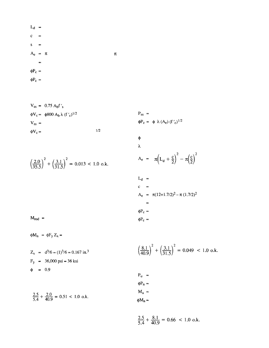
the embedment depth, in.
1.7 (rod diameter)
spacing, in.
(12+1.7/2)
2
+4(12+ 1.7/2)(10+1.7)- (1.7)
2
706.5 in.
2
0.85 (1) 706.5 (4) (3500)
1/2
(1/1000)
142.1 kips
142.1 ÷ 4 = 35.5 kips per rod
Design strength in shear:
0.75(0.785)58 = 34.1 kips
0.85 (800) (0.785) (1) (3500)
(1/1000)
= 31.5 kips
Combining tension and shear per UBC-94, para.
1925.3.4
This establishes the resistance based on the anchor rod
strength and concrete strength at the level of the con-
crete. The rods must also be checked in bending.
Rod in bending and tension.
Moment arm = 0.5(3-1-0.375) = 0.81 in.
3050 x 0.81 in. = 2478 in.-lb.
= 2.5 in.-kip
0.9(36)0.167 = 5.4in.-kip
where
Axial tension is as calculated above.
Combining bending and tension per AISC:
This result can also be found in Table 23 where an allow-
able cable force of 18,114 pounds is given for this geom-
etry, anchor rod and grout combination. This value ex-
ceeds the actual cable force of 11,075 pounds.
Example 5-5
Check the column anchor rods for the forces induced by
the diagonal cable force determined in Design Example
5-1, using a bent plate Type B attachment.
This check is the same as that of Example 5-4 except
that the vertical force component is carried by only the
anchor rod to which the bent plate anchor is secured.
The design for bending and shear is the same.
Axial force: 8.1 kips (one anchor rod only.)
Using the procedure in UBC-94 and section 4.2.5. of
this guide.
Design strength in tension.
40.9 kips as before
where
= 0.85
= 1.0
where
the embedment depth, in.
1.7 (rod diameter)
516.5 in.
2
0.85 (1) 516.5 (4) (3500)
1/2
(1/1000)
103.9 kips
In this case the rod strength governs. The shear strength
is as in Example 5-4 and thus the interaction per
UBC-94 is as follows:
Checking the rod in bending and tension, the bending is
as before. The tension is carried by only one rod.
8.1 kips
40.9 kips, as before
2.5 in.-kips, as before
5.4 in.-kips, as before
Combining bending and tension per AISC:
38
© 2003 by American Institute of Steel Construction, Inc. All rights reserved.
This publication or any part thereof must not be reproduced in any form without permission of the publisher.
This result can also be found in Table 25 where an allow-
able cable force of 13,471 pounds is given for this geom-
etry, anchor rod and grout combination. This value ex-
ceeds the actual cable force of 11,075 pounds.
The footing must also be evaluated to determine its re-
sistance to the cable diagonal force. In this situation the
footing can be evaluated using the procedure developed
for deadmen, which follows.
5.3 Design of Deadmen
On occasion the erector must anchor cable bracing
to a "deadman". A deadman may be constructed on top
of the ground, near the ground surface, or at any depth
within the soil. They may be short in length or continu-
ous.
5.3.1 Surface
Deadmen
The simplest form of a deadman is a mass of dead
weight sitting on top of the ground surface. A block of
concrete is generally used. The anchor resistance pro-
vided by such a deadman is dependent upon the angle
that the bracing cable makes with the deadman and the
location of the bracing cable attachment relative to the
center of gravity of the deadman. As the angle of the
bracing from the horizontal becomes greater, the resis-
tance of the deadman to horizontal sliding reduces.
The resistance to sliding equals the total weight of
the deadman less the upward force from the bracing
cable, times the coefficient of friction between the dead-
man and the soil. A coefficient of friction of 0.5 is gen-
erally used. In equation format:
Eq.5-6
where
= the
nominal
horizontal resistance of the dead-
man
= the
weight
of
the
deadman, lbs.
P = the
required
brace force, lbs.
0.5 = the coefficient of friction
Using a factor of safety of 1.5 for sliding the allowable
resistance is thus:
Eq. 5-7
In addition to satisfying Eq. 5-7 the overturning resis-
tance of the deadman must be checked. This can be ac-
complished by taking moments about the top of the
deadman. A factor of safety of 1.5 is commonly used for
overturning.
5.3.2 Short Deadmen Near Ground Surface
On occasion a deadman may also be buried into the
soil. The deadman must be designed to resist the verti-
cal and horizontal force exerted by the bracing system.
The vertical force is resisted by the weight of the dead-
man. The required weight equals:
where
the weight of the deadman, lbs.
the bracing force, lbs.
the angle measured from the horizontal of the
bracing cable, degrees
1.5 = the factor of safety used for uplift
The horizontal resistance varies depending upon the soil
condition at the site.
Granular Soils
Based on soil mechanics principles the total resis-
tance to sliding can be expressed as:
Eq. 5-9
where
the total nominal horizontal resistance, lbs.
length of the deadman, perpendicular to the
force, ft.
total passive earth pressure, lbs. per lineal ft.
total active earth pressure, lbs. per lineal ft.
coefficient of earth pressure at rest
unit density of the soil, pcf
coefficient of passive earth pressure
coefficient of active earth pressure
depth of the deadman in soil, ft.
angle of internal friction for the soil, degrees
The following values may be used except in unusual sit-
uations:
39
© 2003 by American Institute of Steel Construction, Inc. All rights reserved.
This publication or any part thereof must not be reproduced in any form without permission of the publisher.
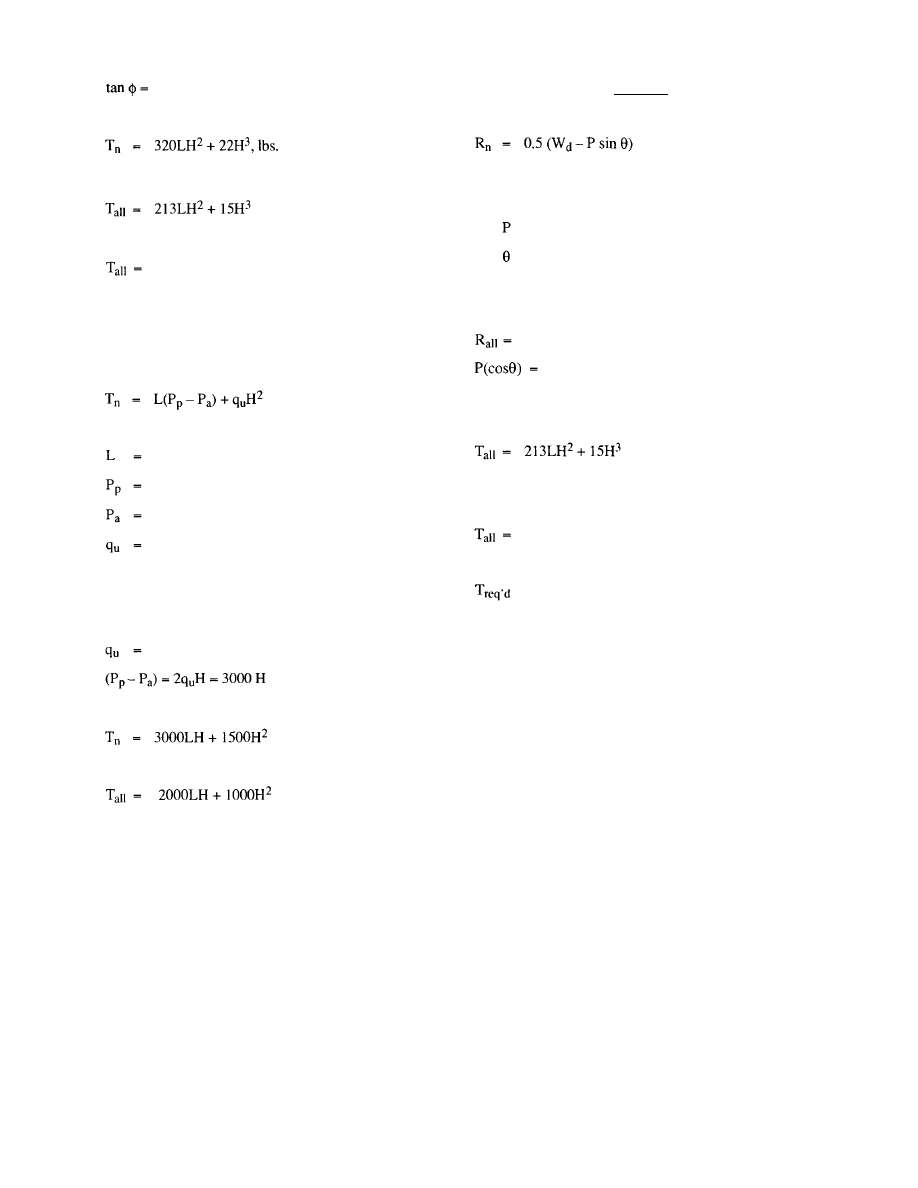
0.6
Thus,
Eq. 5-10
Using a factor of safety of 1.5,
Eq. 5-11
where
the allowable resisting force.
Cohesive Soils
For cohesive soils the ultimate horizontal resis-
tance provided by the deadman can be calculated from
the following equation:
Eq. 5-12
where
the length of the deadman, ft.
total passive earth pressure, lbs. per lineal ft.
total active earth pressure, lbs. per lineal ft.
the unconfined compression strength of the soil,
psf
H = depth of the deadman, ft.
The following values may be used in this equation:
1500 psf (usually conservative)
Thus,
Eq. 5-13
Using a factor of safety of 1.5,
Eq. 5-14
Example 5-6
Check footing as surface deadman.
Footing: 6'-0" x 6'-0" x l'-6"
Soil: Granular type
Calculate weight of footing:
W
d
= 6 x 6 x 1.50 x 0.150 = 8.1 kips
Calculate weight of frame
Column: 25(40) =
1,000 lbs.
Beams: 40(35) =
1,400 lbs.
Girders: 40(68) =
2,720 lbs.
Framing: 40(40)5 = 8.000 lbs.
Total 13,120
lbs.
=
13.1
kips
(Eq. 5-6)
W
d
= 8.1 + 13.1=21.2 kips
From Example 5-1
= 11.1
kips
= 32°
R
n
= 0.5 (21.2 -(11.1 (sin 32°)) = 7.7 kips
Using a factor of safety of 1.5,
0.67(R
n
) = 0.67(7.7) = 5.1 kips
11.1 (cos 32°) = 9.4 kips
5.1 < 9.4 n.g.
Check footing as deadman in ground:
(Eq.5-11)
L = length of deadman, ft.
H =
depth
of
deadman, ft.
213 (6) 1.5
2
+ 15 (1.5)
3
= 2909 lbs. - 2.9 kips
A thicker footing is required
= 9.4 kips
Solving for H
9400 =
213(6)x
2
+ 15(x)
3
x = 2.68ft.
Try a footing: 6'-0" x 6'-0" x 2'-9"
Check overturning. The anchor is attached to the foot-
ing top at the center of the footing:
Overturning moment:
(11.1 sin 32°)(3) + (11.1 cos 32°)(2.75) = 43.5 ft.-kips
Resisting moment:
(6)(6)(2.75)(0.150)(3) + 13.1(3) = 83.8 ft.-kips
Factor of Safety = 89.2/46.6 = 1.9 > 1.5 o.k.
In the foregoing example the size of the footing required
to resist the diagonal cable force was substantially larger
than would be common in the building described else-
where in the examples. The example indicates that the
footing resistance may often be the limiting factor. The
schedule of a construction project may not allow rede-
sign and rebidding to account for changes due to the
erection bracing. In this event the footing and founda-
tions must be taken as a limiting constraint to the erec-
tion bracing design. This condition will result in an in-
crease in the number of diagonal bracing cables
required.
40
© 2003 by American Institute of Steel Construction, Inc. All rights reserved.
This publication or any part thereof must not be reproduced in any form without permission of the publisher.

PART 2
DETERMINATION OF BRACING
REQUIREMENTS USING PRE-
SCRIPTIVE REQUIREMENTS
6. INTRODUCTION TO PART 2
Part 2 presents a series of prescriptive requirements
which if followed eliminates the need to use the calcula-
tion methods, thus simplifying the determination of the
temporary bracing required. The prescriptive require-
ments are:
1. Requirements relating to the permanent
construction, such as bay size, frame layout,
anchor rod characteristics and foundation
characteristics.
2. Requirements
relating
to
the
temporary brac-
ing requirements and minimum requirements
for the sequence of erection and installation of
temporary bracing.
These prescriptive requirements are grouped by ex-
posure category and by size. An illustrative example of
an erection plan incorporating the prescriptive require-
ments is also presented.
7. PRESCRIPTIVE REQUIREMENTS
7.1 Prescriptive Requirements for the Permanent
Construction
Tables 7.1 through 7.24 present prescriptive require-
ments which limit features of the permanent construc-
tion. The features which are critical are:
1. Bay
size.
2. Column
height.
3. Column
size.
4. Base
plate thickness.
5. Pier
size.
6. Footing
size.
7. Column
setting type.
8. Anchor
rod
diameter.
9. Anchor
rod pattern.
10. Anchor rod termination, hooked or nutted.
11. Anchor rod embedment.
12. Anchor rod cover below bottom end.
Three bay sizes are presented: 30-foot, 40-foot
and 50-foot. The column heights presented are:
15-foot, 30-foot and 45-foot. Two types of settings are
presented. The first type loads the anchor rods in com-
pression. This type of base uses leveling nuts. The se-
cond type are those bases which do not transmit com-
pression forces to the anchor rods, namely, pre-grouted
setting plates, shims and anchor rods with an additional
nut installed just below the top surface of the concrete,
as illustrated in Figure 4.17.
If the conditions upon which these tables are based
are present in the construction and the erector follows
the requirements for erection sequence and cable brac-
ing, then no separate analysis for the determination of
temporary supports is required. Both single story and
two story structures are addressed in the tables.
The tables are based on the following parameters:
1. Both
wind exposure categories B and C are tab-
ulated. The exposure category used is to be
that for which the structure is designed.
2. The design wind pressures are those associated
with an 80 mph basic wind speed. The tables
are not be valid for greater speeds. The design
wind speed has been reduced for a six week (or
less) exposure duration as described in para-
graph 3.2.1 of the text. Also a design wind
speed of 35 mph has been used for elements
which are exposed to the wind for a period of
no more than twenty-four hours. This includes
individual columns supported on their bases
and individual beam/column pairs prior to the
installation of tie members. A single row of
beams and columns supported only by their
bases would not meet the limitations of these
tables. In the case of a two story column both
the upper and lower beams may be erected fol-
lowing the limitations cited above for beam/
column pairs.
3. In
calculating
wind forces on frames, 24 inch
deep solid web members and 48 inch deep open
web members were used. Member depths on
the frame lines exceeding these maximums
would invalidate the prescriptive require-
ments. Also, 12 inch deep columns were used.
Greater depth columns would not be valid.
4. With regard to the footings and piers the fol-
lowing parameters are used. The concrete
strength is 3000 psi. This strength is the
28-day cylinder strength which may be
achieved in less than 28 days, but must be con-
firmed by test. The area of reinforcement in
the piers must be at least one half of one percent
of the area of the concrete pier. The factor of
safety against overturning and sliding used is
1.5. In the determination of uplift and over-
41
© 2003 by American Institute of Steel Construction, Inc. All rights reserved.
This publication or any part thereof must not be reproduced in any form without permission of the publisher.
turning resistance, a dead load equal to 4 psf
over the column tributary area plus the footing
weight is used.
5. The
strength
of
the
column
to
base
plate weld is
based on a fillet weld size of 5/16 inch. The
weld must be made to both sides of each flange
and each side of the web. Lesser weld sizes
and/or extents would require calculations as
presented in Part 1.
6. In
several
cases,
hooked anchor rods may be
used per the tables. It is permissible in these
cases to substitute a headed anchor rod with the
same embedment.
7. In the determination of column base moment
strength for columns with setting plates, a mo-
ment arm equal to one half the bolt spacing
plus one half the column flange width is used.
8. In the determination of the diagonal cable
force to be resisted, the degree of base fixity
provided by the column bases is considered.
This has the effect of reducing the required
cable force to be developed.
9. The
tables
require the placement of opposing
pair diagonal cable braces in each frame line in
both orthogonal directions. These braces must
be placed in every fourth bay along the frame
lines in Exposure B conditions and in every
third bay in Exposure C conditions.
10. The diagonal cable brace required for the one
story frames presented is a 1/2 inch diameter
wire rope with a minimum nominal breaking
strength of 21,000 pounds. For the two story
frames, a 5/8 inch diameter wire rope with a
minimum nominal breaking strength of 30,000
pounds is required.
11. The wire rope diagonals can be anchored to the
columns with Type A or Type B anchors as il-
lustrated in Figures 5.2.1 and 5.2.2.
Anchor required for one story frames:
Type A:
Plate thickness =
in.
L = 3 in.
Weld = 3/16 fillets
Grout thickness = 3 in., maximum
TypeB:
Plate thickness -
in.
B = 4 in.
Grout thickness = 2 in., maximum for
in.
diameter anchor rods and 3 in., maximum for
diameters greater than
in.
Anchor required for two story frames:
Type A:
Plate thickness =
in.
L = 4 in.
Weld =
in, fillets
Grout thickness = 2 in., maximum for
in.
diameter anchor rods and 3 in., maximum for
diameters greater than in.
TypeB:
Plate thickness =
in.
B = 5 in.
Grout thickness = 2 in., maximum for
in.
diameter anchor rods and 3 in., maximum for
diameters greater than
in.
Termination of wire rope can be made by wrap-
ping, if the limitations presented in paragraph
5.2 are followed.
7.2 Prescriptive Requirements for Erection Se-
quence and Diagonal Bracing
In addition to the prescriptive requirements for the
permanent structure, there are prescriptive require-
ments for erection sequence and diagonal bracing.
Figure 7.1 illustrates an erection plan with diagonal
bracing in specific bays. It also identifies an initial box
from which the erection is to commence. Figures 7.2
through 7.5 illustrate the build out from the initial box.
The pattern of column, girder, column, girder, tie beam,
x-brace is to be repeated as the erection proceeds. This
limitation on sequence is established to restrict the sur-
face of frame exposed to wind when that portion of the
frame is supported solely by the anchor bolts. The se-
quence given above limits the exposure to one column
and one-half of one beam. In a two story frame, the ex-
posure is limited to one column and one -half each of the
upper and lower beams. The number of braced bays, the
size and strength of wire rope to be used and the anchor-
age required for this wire rope are given in Section 7.1
The erection plan in Figure 7.1 illustrates columns,
girders, tie members and temporary x-braces. This plan
is divided into four erection sequences. Figure 7.1 con-
tains features which are solely illustrative and others
which are prescriptive.
The illustrative features are:
1. Proportion of bay: A square bay is shown and
is required for use of the Tables. The dimen-
sion of the bays are the 30-foot, 40-foot, and
50-foot bays as presented in Tables 7.1
through 7.24. Rectangular bays induce a dif-
ferent set of loads, cable forces and angles and
the prescriptive requirements are not valid. If
the structure to be erected has rectangular bays,
the calculation method must be used.
2. Number
of
bays: An arrangement of five bays
by seven bays is shown. The number of bays in
each direction is not limited.
42
© 2003 by American Institute of Steel Construction, Inc. All rights reserved.
This publication or any part thereof must not be reproduced in any form without permission of the publisher.

3. Columns: A wide flange column is shown.
Pipe and tube columns may also be used.
4. Column
orientation: Any arrangement of col-
umn orientations is permitted.
5. Erection
sequences: Four (I to IV) erection se-
quences are illustrated. The number and pat-
tern of erection sequences is not limited.
6. Starting
point of erection: Erection begins at
the "initial box" in the upper left hand corner of
the plan. The location of the starting point is
not limited; however, at the starting point an
initial box must be formed.
7. Progression
from the initial box: The plan and
the supplementary figures illustrate a progres-
sion from the initial box. This progression fol-
lows this sequence: bay 1-2, B-C, bay 1-2,
C-D, bay 2-3, A-B, etc. The progression from
the initial box can follow any order however it
must follow a bay by bay development in
which beam/column pairs are erected followed
by the erection of the tie members followed by
the installation of the temporary x-brace. This
is illustrated in Figure 7.3, which shows an x-
brace installed between columns C/l and C/2
before the erection proceeds to grid line D.
8. Location
of
x-braces: The
plan shows x-
braces in the exterior bay 1-2. It is not required
that x-braces be located in exterior bays unless
it is necessary to meet the prescriptive require-
ments. X-braces must be located per the pre-
scriptive requirements, namely every third or
fourth bay depending on the exposure catego-
ry, on each frame line, on all four sides of the
initial box and in the bays which proceed out-
ward from the initial box (see Figures 7.2-7.5).
9. Use
of
x-braces: Each opposing cable pair is
shown as an x-brace. The opposing cable pairs
do not necessarily need to be installed as an "x"
except when a single bay is to be braced such as
the four sides of the initial box and the bays
framed out from the initial box (see Figures 7.2
and 7.3).
10. Use of temporary bracing: Figures 7.1 through
7.5 show the use of only temporary bracing.
Permanent bracing may be used; however, this
requires evaluation by the calculation method
(Part 1) to properly determine the interaction
of permanent and temporary bracing.
Lastly, temporary bracing must remain in place un-
til its removal is permitted as provided for in the AISC
Code of Standard Practice.
43
© 2003 by American Institute of Steel Construction, Inc. All rights reserved.
This publication or any part thereof must not be reproduced in any form without permission of the publisher.
Note: Footing thickness given is a minimum which must be
increased to match embedment plus cover in some
cases.
Note: Pier size given is the minimum size required for
strength. A larger pier may be required to match the
column provided.
Note: The anchor rod parameters given are minimums.
Table 7.1 Prescriptive Requirements for
Exposure B, 30 ft. Bays, 15 ft. Column
Height, One Story Frame
Note: Footing thickness given is a minimum which must be
increased to match embedment plus cover in some
cases.
Note: Pier size given is the minimum size required for
strength. A larger pier may be required to match the
column provided.
Note: The anchor rod parameters given are minimums.
Table 7.2 Prescriptive Requirements for
Exposure B, 30 ft. Bays, 30 ft. Column
Height, One Story Frame
44
Exposure Category
Bay Size, ft.
Column Height, ft.
Stories
Column Size
Base Plate, Thickness, in.
Pier Size, in. x in.
Footing Size, ft. x ft. x in.
B
30
15
1
W8X24
0.75
12X12
4.0X4.0X12
Anchor Rods with Leveling Nuts
Anchor Rod, Diameter, in.
Anchor Pattern, in. x in.
Hooked or Nutted
Embedment, in.
Cover Below Anchor, in.
0.75
4X4
3 in. Hook
6
6
Anchor Rods, Base Plate Shimmed or Grouted
Anchor Rod, Diameter, in.
Anchor Pattern, in. x in.
Hooked or Nutted
Embedment, in.
Cover Below Anchor, in.
0.75
4X4
3 in. Hook
6
3
Exposure Category
Bay Size, ft.
Column Height, ft.
Stories
Column Size
Base Plate, Thickness, in.
Pier Size, in. x in.
Footing Size, ft. x ft. x in.
B
30
30
1
W8X31
0.75
12X12
4.5X4.5X12
Anchor Rods with Leveling Nuts
Anchor Rod, Diameter, in.
Anchor Pattern, in. x in.
Hooked or Nutted
Embedment, in.
Cover Below Anchor, in.
0.75
4X4
3 in. Hook
6
6
Anchor Rods, Base Plate Shimmed or Grouted
Anchor Rod, Diameter, in.
Anchor Pattern, in. x in.
Hooked or Nutted
Embedment, in.
Cover Below Anchor, in.
0.75
4X4
3 in. Hook
6
3
© 2003 by American Institute of Steel Construction, Inc. All rights reserved.
This publication or any part thereof must not be reproduced in any form without permission of the publisher.
Exposure Category
Bay Size, ft.
Column Height, ft.
Stories
Column Size
Base Plate, Thickness, in.
Pier Size, in. x in.
Footing Size, ft. x ft. x in.
B
30
45
1
W12X65
1.0
12X12
5.5X5.5X13
Anchor Rods with Leveling Nuts
Anchor Rod, Diameter, in.
Anchor Pattern, in. x in.
Hooked or Nutted
Embedment, in.
Cover Below Anchor, in.
0.875
5X5
4 in. Hook
6
6
Anchor Rods, Base Plate Shimmed or Grouted
Anchor Rod, Diameter, in.
Anchor Pattern, in. x in.
Hooked or Nutted
Embedment, in.
Cover Below Anchor, in.
0.75
5X5
3 in. Hook
6
3
Exposure Category
Bay Size, ft.
Column Height, ft.
Stories
Column Size
Base Plate, Thickness, in.
Pier Size, in. x in.
Footing Size, ft. x ft. x in.
B
40
15
1
W8X24
0.75
12X12
4.0X4.0X12
Anchor Rods with Leveling Nuts
Anchor Rod, Diameter, in.
Anchor Pattern, in. x in.
Hooked or Nutted
Embedment, in.
Cover Below Anchor, in.
0.75
4X4
3 in. Hook
6
6
Anchor Rods, Base Plate Shimmed or Grouted
Anchor Rod, Diameter, in.
Anchor Pattern, in. x in.
Hooked or Nutted
Embedment, in.
Cover Below Anchor, in.
0.75
4X4
3 in. Hook
6
3
Note: Footing thickness given is a minimum which must be
increased to match embedment plus cover in some
cases.
Note: Pier size given is the minimum size required for
strength. A larger pier may be required to match the
column provided.
Note: The anchor rod parameters given are minimums.
Table 7.3 Prescriptive Requirements for
Exposure B, 30 ft. Bays, 45 ft. Column
Height, One Story Frame
Note: Footing thickness given is a minimum which must be
increased to match embedment plus cover in some
cases.
Note: Pier size given is the minimum size required for
strength. A larger pier may be required to match the
column provided.
Note: The anchor rod parameters given are minimums.
Table 7.4 Prescriptive Requirements for
Exposure B, 40 ft. Bays, 15 ft. Column
Height, One Story Frame
45
© 2003 by American Institute of Steel Construction, Inc. All rights reserved.
This publication or any part thereof must not be reproduced in any form without permission of the publisher.
Exposure Category
Bay Size, ft.
Column Height, ft.
Stories
Column Size
Base Plate, Thickness, in.
Pier Size, in. x in.
Footing Size, ft. x ft. x in.
B
40
30
1
W8X31
0.75
12X12
5.0X5.0X12
Anchor Rods with Leveling Nuts
Anchor Rod, Diameter, in.
Anchor Pattern, in. x in.
Hooked or Nutted
Embedment, in.
Cover Below Anchor, in.
0.875
4X4
3 in. Hook
6
9
Anchor Rods, Base Plate Shimmed or Grouted
Anchor Rod, Diameter, in.
Anchor Pattern, in. x in.
Hooked or Nutted
Embedment, in.
Cover Below Anchor, in.
0.75
4X4
3 in. Hook
6
3
Exposure Category
Bay Size, ft.
Column Height, ft.
Stories
Column Size
Base Plate, Thickness, in.
Pier Size, in. x in.
Footing Size, ft. x ft. x in.
B
40
45
1
W12X65
1.0
12X12
5.5X5.5X17
Anchor Rods with Leveling Nuts
Anchor Rod, Diameter, in.
Anchor Pattern, in. x in.
Hooked or Nutted
Embedment, in.
Cover Below Anchor, in.
1.0
5X5
4 in. Hook
6
9
Anchor Rods, Base Plate Shimmed or Grouted
Anchor Rod, Diameter, in.
Anchor Pattern, in. x in.
Hooked or Nutted
Embedment, in.
Cover Below Anchor, in.
1.0
5X5
3 in. Hook
6
3
Note: Footing thickness given is a minimum which must be
increased to match embedment plus cover in some
cases.
Note: Pier size given is the minimum size required for
strength. A larger pier may be required to match the
column provided.
Note: The anchor rod parameters given are minimums.
Table 7.5 Prescriptive Requirements for
Exposure B, 40 ft. Bays, 30 ft. Column
Height, One Story Frame
Note: Footing thickness given is a minimum which must be
increased to match embedment plus cover in some
cases.
Note: Pier size given is the minimum size required for
strength. A larger pier may be required to match the
column provided.
Note: The anchor rod parameters given are minimums.
Table 7.6 Prescriptive Requirements for
Exposure B, 40 ft. Bays, 45 ft. Column
Height, One Story Frame
46
© 2003 by American Institute of Steel Construction, Inc. All rights reserved.
This publication or any part thereof must not be reproduced in any form without permission of the publisher.
Exposure Category
Bay Size, ft.
Column Height, ft.
Stories
Column Size
Base Plate, Thickness, in.
Pier Size, in. x in.
Footing Size, ft. x ft. x in.
B
50
15
1
W8X24
0.75
12X12
4.0X4.0X12
Anchor Rods with Leveling Nuts
Anchor Rod, Diameter, in.
Anchor Pattern, in. x in.
Hooked or Nutted
Embedment, in.
Cover Below Anchor, in.
0.75
4X4
4 in. Hook
6
6
Anchor Rods, Base Plate Shimmed or Grouted
Anchor Rod, Diameter, in.
Anchor Pattern, in. x in.
Hooked or Nutted
Embedment, in.
Cover Below Anchor, in.
0.75
4X4
3 in. Hook
6
3
Exposure Category
Bay Size, ft.
Column Height, ft.
Stories
Column Size
Base Plate, Thickness, in.
Pier Size, in. x in.
Footing Size, ft. x ft. x in.
B
50
30
1
W8X31
0.75
18X18
5.0X5.0X13
Anchor Rods with Leveling Nuts
Anchor Rod, Diameter, in.
Anchor Pattern, in. x in.
Hooked or Nutted
Embedment, in.
Cover Below Anchor, in.
0.875
4X4
4 in. Hook
9
9
Anchor Rods, Base Plate Shimmed or Grouted
Anchor Rod, Diameter, in.
Anchor Pattern, in. x in.
Hooked or Nutted
Embedment, in.
Cover Below Anchor, in.
0.75
4X4
4 in. Hook
9
3
Note: Footing thickness given is a minimum which must be
increased to match embedment plus cover in some
cases.
Note: Pier size given is the minimum size required for
strength. A larger pier may be required to match the
column provided.
Note: The anchor rod parameters given are minimums.
Table 7.7 Prescriptive Requirements for
Exposure B, 50 ft. Bays, 15 ft. Column
Height, One Story Frame
Note: Footing thickness given is a minimum which must be
increased to match embedment plus cover in some
cases.
Note: Pier size given is the minimum size required for
strength. A larger pier may be required to match the
column provided.
Note: The anchor rod parameters given are minimums.
Table 7.8 Prescriptive Requirements for
Exposure B, 50 ft. Bays, 30 ft. Column
Height, One Story Frame
47
© 2003 by American Institute of Steel Construction, Inc. All rights reserved.
This publication or any part thereof must not be reproduced in any form without permission of the publisher.
Exposure Category
Bay Size, ft.
Column Height, ft.
Stories
Column Size
Base Plate, Thickness, in.
Pier Size, in. x in.
Footing Size, ft. x ft. x in.
B
50
45
1
W12X65
1.0
22X22
5.5X5.5X17
Anchor Rods with Leveling Nuts
Anchor Rod, Diameter, in.
Anchor Pattern, in. x in.
Hooked or Nutted
Embedment, in.
Cover Below Anchor, in.
0.75
15X15
3 in. Hook
6
3
Anchor Rods, Base Plate Shimmed or Grouted
Anchor Rod, Diameter, in.
Anchor Pattern, in. x in.
Hooked or Nutted
Embedment, in.
Cover Below Anchor, in.
0.75
15X15
3 in. Hook
6
3
Exposure Category
Bay Size, ft.
Column Height, ft.
Stories
Column Size
Base Plate, Thickness, in.
Pier Size, in. x in.
Footing Size, ft. x ft. x in.
C
30
15
1
W8X24
0.75
12X12
4.0X4.0X12
Anchor Rods with Leveling Nuts
Anchor Rod, Diameter, in.
Anchor Pattern, in. x in.
Hooked or Nutted
Embedment, in.
Cover Below Anchor, in.
0.75
4X4
3 in. Hook
6
6
Anchor Rods, Base Plate Shimmed or Grouted
Anchor Rod, Diameter, in.
Anchor Pattern, in. x in.
Hooked or Nutted
Embedment, in.
Cover Below Anchor, in.
0.75
4X4
3 in. Hook
6
3
Note: Footing thickness given is a minimum which must be
increased to match embedment plus cover in some
cases.
Note: Pier size given is the minimum size required for
strength. A larger pier may be required to match the
column provided.
Note: The anchor rod parameters given are minimums.
Table 7.9 Prescriptive Requirements for
Exposure B, 50 ft. Bays, 45 ft. Column
Height, One Story Frame
Note: Footing thickness given is a minimum which must be
increased to match embedment plus cover in some
cases.
Note: Pier size given is the minimum size required for
strength. A larger pier may be required to match the
column provided.
Note: The anchor rod parameters given are minimums.
Table 7.10 Prescriptive Requirements for
Exposure C, 30 ft. Bays, 15 ft. Column
Height, One Story Frame
48
© 2003 by American Institute of Steel Construction, Inc. All rights reserved.
This publication or any part thereof must not be reproduced in any form without permission of the publisher.

Exposure Category
Bay Size, ft.
Column Height, ft.
Stories
Column Size
Base Plate, Thickness, in.
Pier Size, in. x in.
Footing Size, ft. x ft. x in.
C
30
30
1
W8X31
0.75
12X12
5.0X5.0X12
Anchor Rods with Leveling Nuts
Anchor Rod, Diameter, in.
Anchor Pattern, in. x in.
Hooked or Nutted
Embedment, in.
Cover Below Anchor, in.
0.75
11X11
3 in. Hook
6
6
Anchor Rods, Base Plate Shimmed or Grouted
Anchor Rod, Diameter, in.
Anchor Pattern, in. x in.
Hooked or Nutted
Embedment, in.
Cover Below Anchor, in.
0.75
4X4
4 in. Hook
9
3
Exposure Category
Bay Size, ft.
Column Height, ft.
Stories
Column Size
Base Plate, Thickness, in.
Pier Size, in. x in.
Footing Size, ft. x ft. x in.
C
30
45
1
W12X65
1.0
12X12
6.0X6.0X15
Anchor Rods with Leveling Nuts
Anchor Rod, Diameter, in.
Anchor Pattern, in. x in.
Hooked or Nutted
Embedment, in.
Cover Below Anchor, in.
0.75
15X15
3 in. Hook
6
6
Anchor Rods, Base Plate Shimmed or Grouted
Anchor Rod, Diameter, in.
Anchor Pattern, in. x in.
Hooked or Nutted
Embedment, in.
Cover Below Anchor, in.
0.75
15X15
4 in. Hook
9
3
Note: Footing thickness given is a minimum which must be
increased to match embedment plus cover in some
cases.
Note: Pier size given is the minimum size required for
strength. A larger pier may be required to match the
column provided.
Note: The anchor rod parameters given are minimums.
Table 7.11 Prescriptive Requirements for
Exposure C, 30 ft. Bays, 30 ft. Column
Height, One Story Frame
Note: Footing thickness given is a minimum which must be
increased to match embedment plus cover in some
cases.
Note: Pier size given is the minimum size required for
strength. A larger pier may be required to match the
column provided.
Note: The anchor rod parameters given are minimums.
Table 7.12 Prescriptive Requirements for
Exposure C, 30 ft. Bays, 45 ft. Column
Height, One Story Frame
49
© 2003 by American Institute of Steel Construction, Inc. All rights reserved.
This publication or any part thereof must not be reproduced in any form without permission of the publisher.

Exposure Category
Bay Size, ft.
Column Height, ft.
Stories
Column Size
Base Plate, Thickness, in.
Pier Size, in. x in.
Footing Size, ft. x ft. x in.
C
40
15
1
W8X24
0.75
12X12
4.0X4.0X12
Anchor Rods with Leveling Nuts
Anchor Rod, Diameter, in.
Anchor Pattern, in. x in.
Hooked or Nutted
Embedment, in.
Cover Below Anchor, in.
0.75
4X4
3 in. Hook
6
6
Anchor Rods, Base Plate Shimmed or Grouted
Anchor Rod, Diameter, in.
Anchor Pattern, in. x in.
Hooked or Nutted
Embedment, in.
Cover Below Anchor, in.
0.75
4X4
3 in. Hook
6
3
Exposure Category
Bay Size, ft.
Column Height, ft.
Stories
Column Size
Base Plate, Thickness, in.
Pier Size, in. x in.
Footing Size, ft. x ft. x in.
C
40
30
1
W8X31
0.75
12X12
5.5X5.5X13
Anchor Rods with Leveling Nuts
Anchor Rod, Diameter, in.
Anchor Pattern, in. x in.
Hooked or Nutted
Embedment, in.
Cover Below Anchor, in.
0.75
11X11
3 in. Hook
9
6
Anchor Rods, Base Plate Shimmed or Grouted
Anchor Rod, Diameter, in.
Anchor Pattern, in. x in.
Hooked or Nutted
Embedment, in.
Cover Below Anchor, in.
1.0
4X4
5 in. Hook
9
3
Note: Footing thickness given is a minimum which must be
increased to match embedment plus cover in some
cases.
Note: Pier size given is the minimum size required for
strength. A larger pier may be required to match the
column provided.
Note: The anchor rod parameters given are minimums.
Table 7.13 Prescriptive Requirements for
Exposure C, 40 ft. Bays, 15 ft. Column
Height, One Story Frame
Note: Footing thickness given is a minimum which must be
increased to match embedment plus cover in some
cases.
Note: Pier size given is the minimum size required for
strength. A larger pier may be required to match the
column provided.
Note: The anchor rod parameters given are minimums.
Table 7.14 Prescriptive Requirements for
Exposure C, 40 ft. Bays, 30 ft. Column
Height, One Story Frame
50
© 2003 by American Institute of Steel Construction, Inc. All rights reserved.
This publication or any part thereof must not be reproduced in any form without permission of the publisher.
Exposure Category
Bay Size, ft.
Column Height, ft.
Stories
Column Size
Base Plate, Thickness, in.
Pier Size, in. x in.
Footing Size, ft. x ft. x in.
C
40
45
1
W12X65
1.25
12X12
6.0X6.0X18
Anchor Rods with Leveling Nuts
Anchor Rod, Diameter, in.
Anchor Pattern, in. x in.
Hooked or Nutted
Embedment, in.
Cover Below Anchor, in.
1.0
15X15
3 in. Hook
9
6
Anchor Rods, Base Plate Shimmed or Grouted
Anchor Rod, Diameter, in.
Anchor Pattern, in. x in.
Hooked or Nutted
Embedment, in.
Cover Below Anchor, in.
1.0
15X15
3 in. Hook
9
3
Exposure Category
Bay Size, ft.
Column Height, ft.
Stories
Column Size
Base Plate, Thickness, in.
Pier Size, in. x in.
Footing Size, ft. x ft. x in.
C
50
15
1
W8X24
0.75
12X12
4.5X4.5X12
Anchor Rods with Leveling Nuts
Anchor Rod, Diameter, in.
Anchor Pattern, in. x in.
Hooked or Nutted
Embedment, in.
Cover Below Anchor, in.
0.75
4X4
3 in. Hook
6
3
Anchor Rods, Base Plate Shimmed or Grouted
Anchor Rod, Diameter, in.
Anchor Pattern, in. x in.
Hooked or Nutted
Embedment, in.
Cover Below Anchor, in.
0.75
4X4
3 in. Hook
6
3
Note: Footing thickness given is a minimum which must be
increased to match embedment plus cover in some
cases.
Note: Pier size given is the minimum size required for
strength. A larger pier may be required to match the
column provided.
Note: The anchor rod parameters given are minimums.
Table 7.15 Prescriptive Requirements for
Exposure C, 40 ft. Bays, 45 ft. Column
Height, One Story Frame
Note: Footing thickness given is a minimum which must be
increased to match embedment plus cover in some
cases.
Note: Pier size given is the minimum size required for
strength. A larger pier may be required to match the
column provided.
Note: The anchor rod parameters given are minimums.
Table 7.16 Prescriptive Requirements for
Exposure C, 50 ft. Bays, 15 ft. Column
Height, One Story Frame
51
© 2003 by American Institute of Steel Construction, Inc. All rights reserved.
This publication or any part thereof must not be reproduced in any form without permission of the publisher.
Exposure Category
Bay Size, ft.
Column Height, ft.
Stories
Column Size
Base Plate, Thickness, in.
Pier Size, in. x in.
Footing Size, ft. x ft. x in.
C
50
30
1
W8X31
0.875
12X12
5.5X5.5X17
Anchor Rods with Leveling Nuts
Anchor Rod, Diameter, in.
Anchor Pattern, in. x in.
Hooked or Nutted
Embedment, in.
Cover Below Anchor, in.
0.75
11X11
4 in. Hook
6
6
Anchor Rods, Base Plate Shimmed or Grouted
Anchor Rod, Diameter, in.
Anchor Pattern, in. x in.
Hooked or Nutted
Embedment, in.
Cover Below Anchor, in.
1.0
4X4
5 in. Hook
9
3
Exposure Category
Bay Size, ft.
Column Height, ft.
Stories
Column Size
Base Plate, Thickness, in.
Pier Size, in. x in.
Footing Size, ft. x ft. x in.
C
50
45
1
W12X65
1.25
12X12
6.5X6.5X16
Anchor Rods with Leveling Nuts
Anchor Rod, Diameter, in.
Anchor Pattern, in. x in.
Hooked or Nutted
Embedment, in.
Cover Below Anchor, in.
1.0
15X15
4 in. Hook
6
9
Anchor Rods, Base Plate Shimmed or Grouted
Anchor Rod, Diameter, in.
Anchor Pattern, in. x in.
Hooked or Nutted
Embedment, in.
Cover Below Anchor, in.
1.0
15X15
4 in. Hook
9
3
Note: Footing thickness given is a minimum which must be
increased to match embedment plus cover in some
cases.
Note: Pier size given is the minimum size required for
strength. A larger pier may be required to match the
column provided.
Note: The anchor rod parameters given are minimums.
Table 7.17 Prescriptive Requirements for
Exposure C, 50 ft. Bays, 30 ft. Column
Height, One Story Frame
Note: Footing thickness given is a minimum which must be
increased to match embedment plus cover in some
cases.
Note: Pier size given is the minimum size required for
strength. A larger pier may be required to match the
column provided.
Note: The anchor rod parameters given are minimums.
Table 7.18 Prescriptive Requirements for
Exposure C, 50 ft. Bays, 45 ft. Column
Height, One Story Frame
52
© 2003 by American Institute of Steel Construction, Inc. All rights reserved.
This publication or any part thereof must not be reproduced in any form without permission of the publisher.
Exposure Category
Bay Size, ft.
Column Height, ft.
Stories
Column Size
Base Plate, Thickness, in.
Pier Size, in. x in.
Footing Size, ft. x ft. x in.
B
30
20
2
W8X31
0.75
12X12
5.0X5.0X18
Anchor Rods with Leveling Nuts
Anchor Rod, Diameter, in.
Anchor Pattern, in. x in.
Hooked or Nutted
Embedment, in.
Cover Below Anchor, in.
0.875
4X4
4 in. Hook
9
9
Anchor Rods, Base Plate Shimmed or Grouted
Anchor Rod, Diameter, in.
Anchor Pattern, in. x in.
Hooked or Nutted
Embedment, in.
Cover Below Anchor, in.
0.75
4X4
3 in. Hook
6
3
Exposure Category
Bay Size, ft.
Column Height, ft.
Stories
Column Size
Base Plate, Thickness, in.
Pier Size, in. x in.
Footing Size, ft. x ft. x in.
B
40
30
2
W8X31
0.75
12X12
5.0X5.0X18
Anchor Rods with Leveling Nuts
Anchor Rod, Diameter, in.
Anchor Pattern, in. x in.
Hooked or Nutted
Embedment, in.
Cover Below Anchor, in.
1.0
4X4
5 in. Hook
9
9
Anchor Rods, Base Plate Shimmed or Grouted
Anchor Rod, Diameter, in.
Anchor Pattern, in. x in.
Hooked or Nutted
Embedment, in.
Cover Below Anchor, in.
0.875
4X4
4 in. Hook
6
3
Note: Footing thickness given is a minimum which must be
increased to match embedment plus cover in some
cases.
Note: Pier size given is the minimum size required for
strength. A larger pier may be required to match the
column provided.
Note: The anchor rod parameters given are minimums.
Table 7.19 Prescriptive Requirements for
Exposure B, 30 ft. Bays, 20 ft. Column
Height, Two Story Frame
Note: Footing thickness given is a minimum which must be
increased to match embedment plus cover in some
cases.
Note: Pier size given is the minimum size required for
strength. A larger pier may be required to match the
column provided.
Note: The anchor rod parameters given are minimums.
Table 7.20 Prescriptive Requirements for
Exposure B, 40 ft. Bays, 30 ft. Column
Height, Two Story Frame
53
© 2003 by American Institute of Steel Construction, Inc. All rights reserved.
This publication or any part thereof must not be reproduced in any form without permission of the publisher.
Exposure Category
Bay Size, ft.
Column Height, ft.
Stories
Column Size
Base Plate, Thickness, in.
Pier Size, in. x in.
Footing Size, ft. x ft. x in.
B
50
30
2
W8X31
0.75
12X12
5.0X5.0X18
Anchor Rods with Leveling Nuts
Anchor Rod, Diameter, in.
Anchor Pattern, in. x in.
Hooked or Nutted
Embedment, in.
Cover Below Anchor, in.
1.0
4X4
5 in. Hook
9
9
Anchor Rods, Base Plate Shimmed or Grouted
Anchor Rod, Diameter, in.
Anchor Pattern, in. x in.
Hooked or Nutted
Embedment, in.
Cover Below Anchor, in.
0.875
4X4
4 in. Hook
9
3
Exposure Category
Bay Size, ft.
Column Height, ft.
Stories
Column Size
Base Plate, Thickness, in.
Pier Size, in. x in.
Footing Size, ft. x ft. x in.
C
30
30
2
W8X31
0.75
12X12
5.0X5.0X18
Anchor Rods with Leveling Nuts
Anchor Rod, Diameter, in.
Anchor Pattern, in. x in.
Hooked or Nutted
Embedment, in.
Cover Below Anchor, in.
1.0
4X4
5 in. Hook
9
9
Anchor Rods, Base Plate Shimmed or Grouted
Anchor Rod, Diameter, in.
Anchor Pattern, in. x in.
Hooked or Nutted
Embedment, in.
Cover Below Anchor, in.
0.875
4X4
5 in. Hook
9
3
Note: Footing thickness given is a minimum which must be
increased to match embedment plus cover in some
cases.
Note: Pier size given is the minimum size required for
strength. A larger pier may be required to match the
column provided.
Note: The anchor rod parameters given are minimums.
Table 7.21 Prescriptive Requirements for
Exposure B, 50 ft. Bays, 30 ft. Column
Height, Two Story Frame
Note: Footing thickness given is a minimum which must be
increased to match embedment plus cover in some
cases.
Note: Pier size given is the minimum size required for
strength. A larger pier may be required to match the
column provided.
Note: The anchor rod parameters given are minimums.
Table 7.22 Prescriptive Requirements for
Exposure C, 30 ft. Bays, 30 ft. Column
Height, Two Story Frame
54
© 2003 by American Institute of Steel Construction, Inc. All rights reserved.
This publication or any part thereof must not be reproduced in any form without permission of the publisher.

Exposure Category
Bay Size, ft.
Column Height, ft.
Stories
Column Size
Base Plate, Thickness, in.
Pier Size, in. x in.
Footing Size, ft. x ft. x in.
C
40
30
2
W8X31
1.0
12X12
5.0X5.0X18
Anchor Rods with Leveling Nuts
Anchor Rod, Diameter, in.
Anchor Pattern, in. x in.
Hooked or Nutted
Embedment, in.
Cover Below Anchor, in.
0.75
11X11
3 in. Hook
6
6
Anchor Rods, Base Plate Shimmed or Grouted
Anchor Rod, Diameter, in.
Anchor Pattern, in. x in.
Hooked or Nutted
Embedment, in.
Cover Below Anchor, in.
1.0
4X4
4 in. Hook
9
3
Exposure Category
Bay Size, ft.
Column Height, ft.
Stories
Column Size
Base Plate, Thickness, in.
Pier Size, in. x in.
Footing Size, ft. x ft. x in.
C
50
30
2
W8X31
1.0
12X12
6.0X6.0X14
Anchor Rods with Leveling Nuts
Anchor Rod, Diameter, in.
Anchor Pattern, in. x in.
Hooked or Nutted
Embedment, in.
Cover Below Anchor, in.
0.875
11X11
4 in. Hook
9
9
Anchor Rods, Base Plate Shimmed or Grouted
Anchor Rod, Diameter, in.
Anchor Pattern, in. x in.
Hooked or Nutted
Embedment, in.
Cover Below Anchor, in.
0.875
11X11
4 in. Hook
9
3
Note: Footing thickness given is a minimum which must be
increased to match embedment plus cover in some
cases.
Note: Pier size given is the minimum size required for
strength. A larger pier may be required to match the
column provided.
Note: The anchor rod parameters given are minimums.
Table 7.23 Prescriptive Requirements for
Exposure C, 40 ft. Bays, 30 ft. Column
Height, Two Story Frame
Note: Footing thickness given is a minimum which must be
increased to match embedment plus cover in some
cases.
Note: Pier size given is the minimum size required for
strength. A larger pier may be required to match the
column provided.
Note: The anchor rod parameters given are minimums.
Table 7.24 Prescriptive Requirements for
Exposure C, 50 ft. Bays, 30 ft. Column
Height, Two Story Frame
55
© 2003 by American Institute of Steel Construction, Inc. All rights reserved.
This publication or any part thereof must not be reproduced in any form without permission of the publisher.
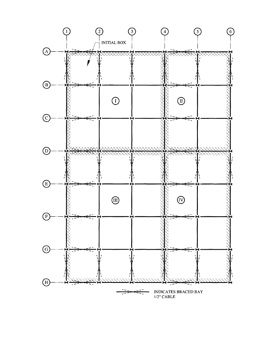
Fig. 7.1 Erection Plan
56
© 2003 by American Institute of Steel Construction, Inc. All rights reserved.
This publication or any part thereof must not be reproduced in any form without permission of the publisher.
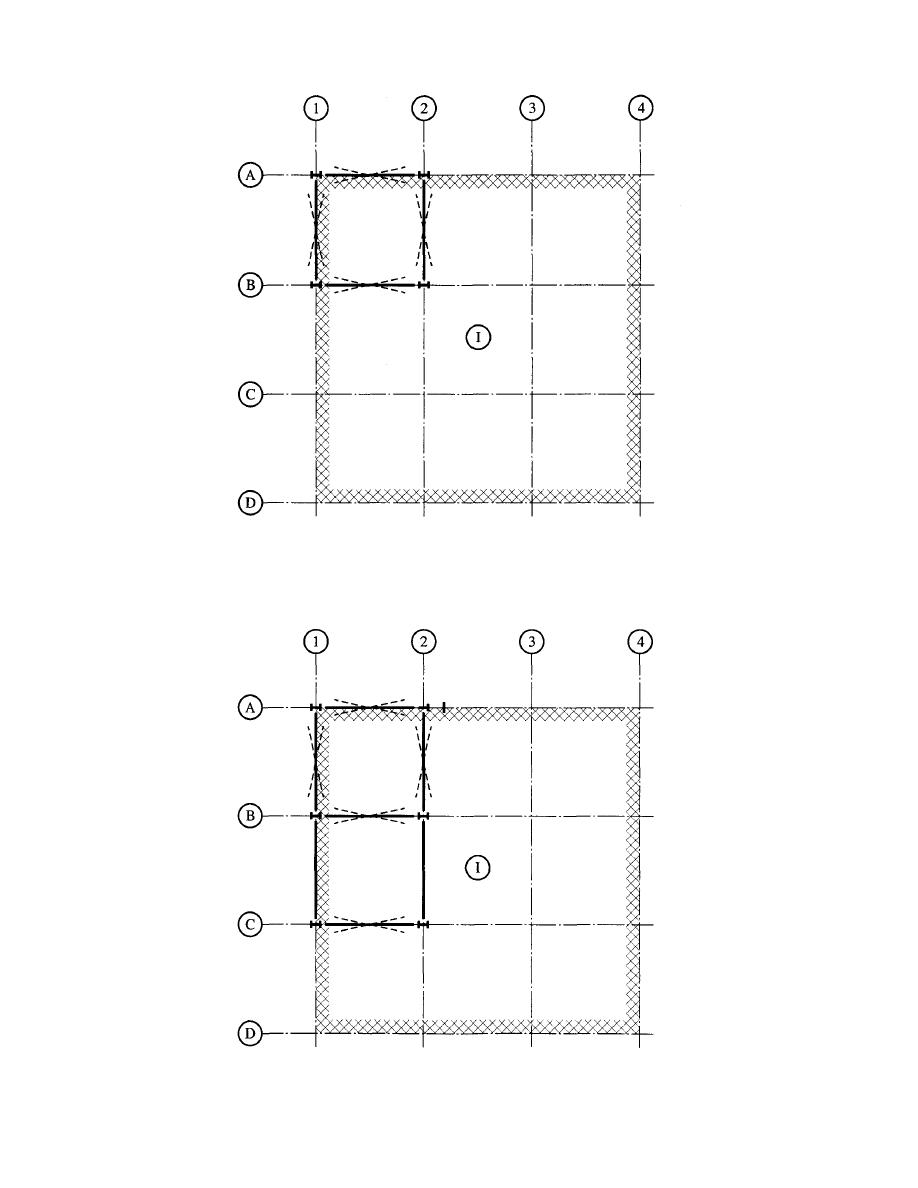
Fig. 7.2 Initial Braced Box
Fig. 7.3 Build Out from Initial Box
57
© 2003 by American Institute of Steel Construction, Inc. All rights reserved.
This publication or any part thereof must not be reproduced in any form without permission of the publisher.
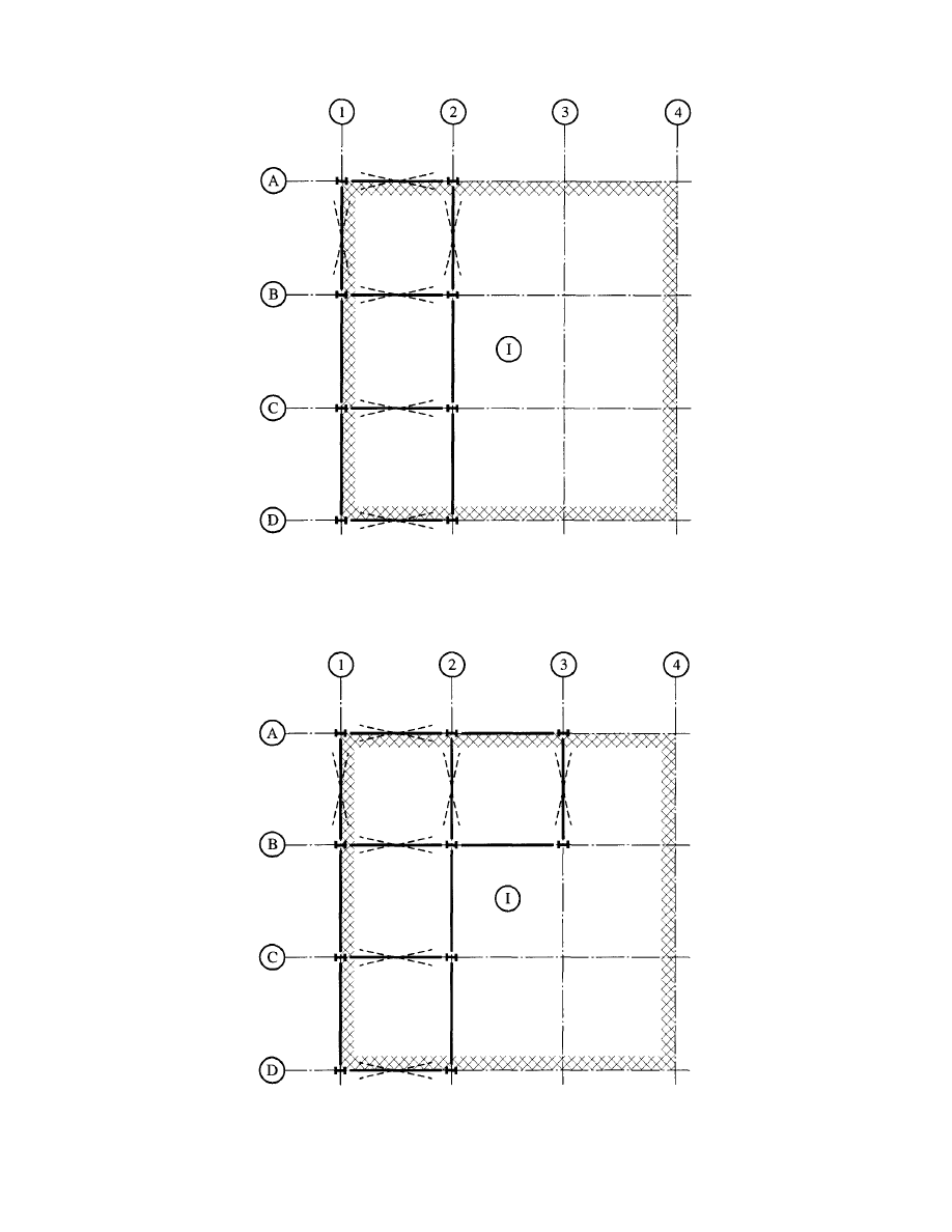
Fig. 7.4 Build Out from Initial Box, Continued
Fig. 7.5 Build Out from Initial Box, Continued
58
© 2003 by American Institute of Steel Construction, Inc. All rights reserved.
This publication or any part thereof must not be reproduced in any form without permission of the publisher.

REFERENCES
1. "American
Society
of
Civil Engineers - Minimum
Design Loads for Buildings and Other Structures",
ASCE7/ANSI A58.1-1993, American Society of
Civil Engineers, New York, New York
2. "Building
Code Requirements for Masonry Struc-
tures", ACI 530, 1992, American Concrete Insti-
tute, Detroit, Michigan
3. "Building
Code Requirements for Reinforced
Concrete", ACI 318, 1995, American Concrete
Institute, Detroit, Michigan
4. "Code
Requirements
for
Nuclear
Safety
Related
Concrete Structures", ACI 349-90, "Appendix B
- Steel Embedments", American Concrete Insti-
tute, Detroit, Michigan, 1990
5.
"Design Loads for Buildings" German Industrial
Standard 1055, 1986, German Institute for Stan-
dards, Berlin, Germany
6. "Design
Loads on Structures During Construc-
tion", proposed American Society of Civil Engi-
neers Standard, 6/95 Draft, American Society of
Civil Engineers, New York, New York
7.
DeWolf, John T. and Ricker, David T., "Column
Base Plates", AISC Steel Design Guide Series, No.
1, 1990, American Institute of Steel Construction,
Chicago, Illinois
8. "Diaphragm
Design Manual", Second Edition,
Steel Deck Institute, Inc., Canton, Ohio, 1987
9.
"Falsework Manual", State of California, Depart-
ment of Transportation, Sacramento, California
10. Fisher,
James M., "Industrial Buildings - Roof to
Column Anchorage", AISC Steel Design Guide
Series, No. 7, 1993, American Institute of Steel
Construction, Chicago, Illinois
11. Fisher,
James M. and West, Michael A., "Erection
Bracing of Structural Steel Frames", Proceedings,
National Steel Construction Conference, Ameri-
can Institute of Steel Construction, 1995
12. "Low
Rise Building Systems Manual", 1986, Met-
al Building Manufacturers Association, Cleve-
land, Ohio
13. "Manual
of
Steel Construction - Volume II -Con-
nections", ASD, 9th Edition/LRFD, 1st Edition,
American Institute of Steel Construction, Chica-
go, Illinois, 1992
14. "Manual
of
Steel Construction - Load and Resis-
tance Factor Design", Vols. I and II, 2nd Edition,
59
American Institute of Steel Construction, Chica-
go, Illinois, 1994
15. "Seismic Provisions for Structural Steel Build-
ings", 1992, American Institute of Steel Construc-
tion, Chicago, Illinois
16. "Standards for Load Assumptions, Acceptance
and Inspections of Structures", 1956, No. 160,
Swiss Association of Engineers and Architects,
Zurich, Switzerland
17. "Uniform
Building Code", Volumes 1-3,1994, In-
ternational Conference of Building Officials,
Whittier, California
18. "Wind Forces on Structures", ASCE Transactions,
Paper No. 3269, American Society of Civil Engi-
neers, New York, New York
19. "Wire Rope Users Manual", 3rd Edition, Wire
Rope Technical Board, Woodstock, Maryland,
1993
© 2003 by American Institute of Steel Construction, Inc. All rights reserved.
This publication or any part thereof must not be reproduced in any form without permission of the publisher.

Acknowledgements
The authors wish to thank the American Institute of
Steel Construction for funding the preparation of this
Guide and the members of the AISC Committee on
Manuals, Textbooks and Codes for their review of the
Guide and their useful comments. Appreciation is due
to Stephen M. Herlache for his assistance in preparing
the many Tables and to Carol T. Williams for typing the
manuscript.
60
© 2003 by American Institute of Steel Construction, Inc. All rights reserved.
This publication or any part thereof must not be reproduced in any form without permission of the publisher.

APPENDIX
Annotated Table of Contents
Table A-l Moment Resistance of Base Plates
with Inset Anchor Rods Based on Weld
Strength
For the column sizes indicated the weak axis mo-
ment resistance for the column to base plate connec-
tion is provided. The failure mode is shown in Figure
4-1. The design strengths are based on Eqs. 4-1 and
4-2 using a
in. weld pattern as shown in Figure
4-21.
Table A-2 Moment Resistance of Base Plates
with Inset Anchor Rods Based on Plate
Strength
Design strengths are provided for the parameters
shown in the table, based on Eqs. 4—3 and 4—4.
Table A-3 Moment Resistance of Base Plates
with Outset Anchor Rods
For the column sizes indicated the design strengths
for the column to base plate connection is provided for
the condition where the anchor rods are outside the
footprint of the column. Due to the configuration of
the anchor rods, the design strengths are applicable to
loads applied about either axis of the column. The de-
sign strength is based on Eq. 4-6 using inch fillet
weld two inches long, and the anchor rod offset from
the flange tip by 2 in. in each direction.
Table A-4 Moment Resistance of Tube Column
Base Plates
For the column sizes and anchor rod spacings
shown the design strength of column base plate is pro-
vided. The tables are based on 4 in. long inch
welds and E70 electrodes and the anchor rod offset
from the flange tip by 2 in. in each direction. The col-
umns are assumed to be welded all around. The design
strengths are based on Eq. 4-9.
Table A-5 Tension Resistance of Anchor Rods
Based on Anchor Rod Strength
Provided in Table A-5 are the tension design
strengths for the A36 anchor rods. The values pro-
vided in the Table are taken directly from the AISC
Manual of Steel Construction. The
failure mode
associated with the Table values is that of anchor rod
fracture as shown in Figure 4-3.
Table A-6 Tension Resistance of Hooked Anchor
Rods Based on Hook Length,
3000
psi
The values provided in Table A-6 are derived from
Eq. 4-14. The values are somewhat conservative in
that no allowance for strength is provided for any bond
between the anchor rod and the concrete. It is the au-
thors opinion that inclusion of the bond strength can be
unconservative since anchor rods are often oily after
the threads are cut. The values provided in Table A-6
are based on a concrete strength of 3000 psi.
Table A-7 Tension Resistance of Hooked Anchor
Rods Based on Hook Length,
4000
psi
Table A-7 is identical to Table A-6 except that a
concrete strength of 4000 psi is used to determine the
provided values.
Table A-8 Tension Resistance of Single Anchor
Rods Based on Concrete Pull Out Ca-
pacity
Presented in Table A-8 are pull out resistance for
the anchor rod sizes and embedment depths shown.
The concrete strength used for the calculations is 3000
psi. The values are for single anchor rods, i.e. no group
action. The values are based on the pull out strength
of the concrete cone, which equals
times the
projected area, of
the
cone at the surface of the con-
crete.
Tables A-9, A-10, A-ll and A-12 Tension Resis-
tance of Two Anchor Rods Based on
Spacing and Embedment
Pull out resistance for a group of two anchor rods
are presented. The Tables are based on a concrete
strength of 3000 psi, and embedment depths equal to
9, 12, 15 and 18 inches. Eq. 4—13 is used to determine
the values.
Table A-13 Compression Resistance of Single An-
chor Rods Based on Concrete Push
Out
Push out values for single anchor rods are pres-
ented in Table A-13. Eq. 4-16 and the failure cone
area shown in Figure 18 are used to calculate the table
values. A concrete strength of 3000 psi is used. The
table values can be used for both hooked rods and
nutted rods.
Table A-14 Compression Resistance of Two An-
chor Rods Based on Concrete Push
Out
Push out values for a group of two anchor rods are
provided. Eq. 4-16 is used to determine the values
61
© 2003 by American Institute of Steel Construction, Inc. All rights reserved.
This publication or any part thereof must not be reproduced in any form without permission of the publisher.

shown. A concrete strength of 3000 psi is used. A
clear cover of 3 inches under the nut or hook of the an-
chor rod is used to determine the push through values
shown.
Tables A-15, A-16 and A-17 Compression Resis-
tance of Two Anchor Rods Based on
Concrete Push Out
Tables A-15, A-16 and A-17 are identical to Table
A-14 with the exception that clear covers of 6, 9 and
12 inches are used respectively.
Table A-18 Concrete Pier Bending Resistance
Bending design strengths are provided for the data
shown in the Table. Eq. 4-17 is used with a concrete
strength of 3000 psi to determine the listed values.
Table A-19 Concrete Footing Overturning Resis-
tance
Overturning resistances are provided for the foot-
ing sizes shown in the Table. The values are based on
Eq. 4-21. Only the dead weight of the footing is used
in determining the values.
Table A-20 Reinforcing Bar Development
Lengths,
3000 psi
The required development length for hooked and
straight reinforcing bars are shown in Table A-20.
Eqs. 18,19 and 20 with a concrete strength of 3000 psi
are used to determine the development lengths.
Table A-21 Reinforcing Bar Development
Lengths, =
4000 psi
Table A-21 is identical to Table A-20 with the ex-
ception that a f
c
of 4000 psi is used in the calculations.
Table A-22 Dimensions of Type A Anchor Plates
and Welds
This table provides plate height, thickness and fil-
let weld size for an A36 plate Type A, for the cable type
and slopes presented. A plate of this geometry and at-
tachment will develop the cable design force using a
minimum factor of safety of 3 in selecting the cable.
The Type A plate is shown in Figure 5.2.1. The table
data was determined using the calculation method in
Example 5-2.
Table A-23 Allowable Cable Force, Type A Plate
Anchor as Limited by Anchor Rod Ca-
pacity
This table provides the maximum Unfactored cable
force for the parameters presented based on the cal-
culation method and material strengths in Example
5-4.
Table A-24 Dimensions of Type B Anchor Plates
and Welds
This table provides the plate width and thickness
for an A36 plate Type B, for the cable types and slopes
presented. A plate of this geometry will develop the
cable design force using a minimum factor of safety of
3 in selecting the cable. The Type B plate is shown in
Figure 5.2.2. The table data was determined using the
calculation method in Example 5-3.
Table A-25 Allowable Cable Force, Type B Plate
Anchor as Limited by Anchor Rod Ca-
pacity
This table provides the maximum Unfactored cable
force for the parameters presented based on the cal-
culation method and material strengths in Example
5-6.
62
© 2003 by American Institute of Steel Construction, Inc. All rights reserved.
This publication or any part thereof must not be reproduced in any form without permission of the publisher.
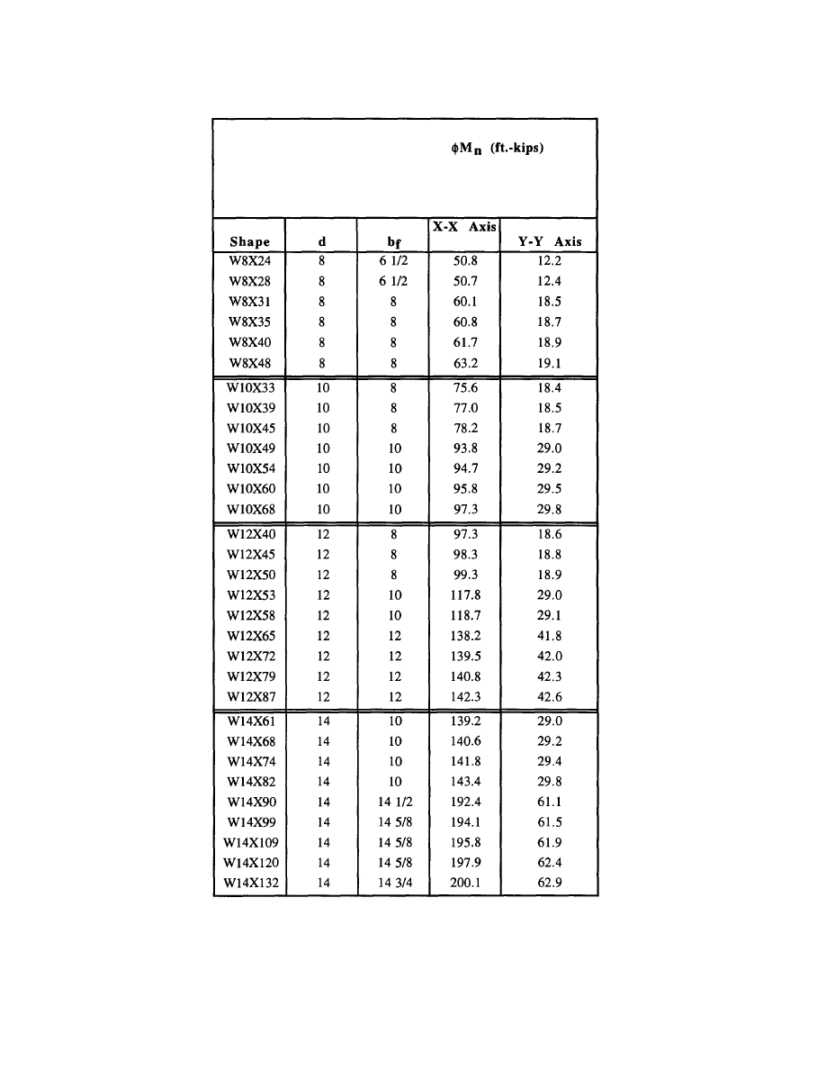
MOMENT RESISTANCE,
Table A-l Moment Resistance of Base Plates with
Inset Anchor Rods Based on Weld Strength
63
BASE PLATES WITH INSET ANCHOR RODS
5/16 inch fillet welds
E70XX Electrode
© 2003 by American Institute of Steel Construction, Inc. All rights reserved.
This publication or any part thereof must not be reproduced in any form without permission of the publisher.
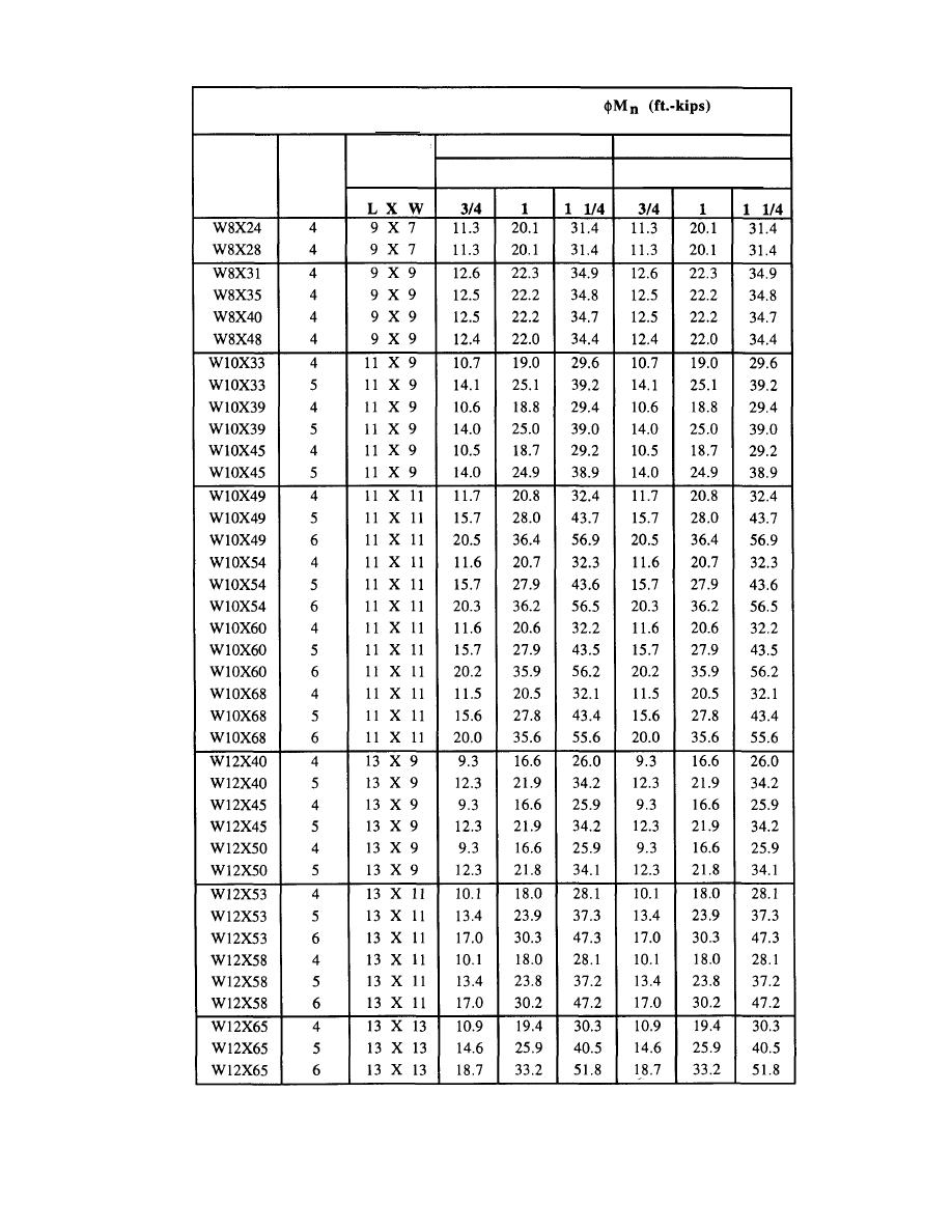
Table A-2 Moment Resistance of Base Plates with
Inset Anchor Rods Based on Plate Strength
64
BASE PLATE BENDING RESISTANCE,
WITH INSET ANCHOR RODS
Shape
Anchor
Rod
Spacing
Base Plate
Plan Size
X-X Axis
Plate Thickness
Y-Y Axis
Plate Thickness
© 2003 by American Institute of Steel Construction, Inc. All rights reserved.
This publication or any part thereof must not be reproduced in any form without permission of the publisher.
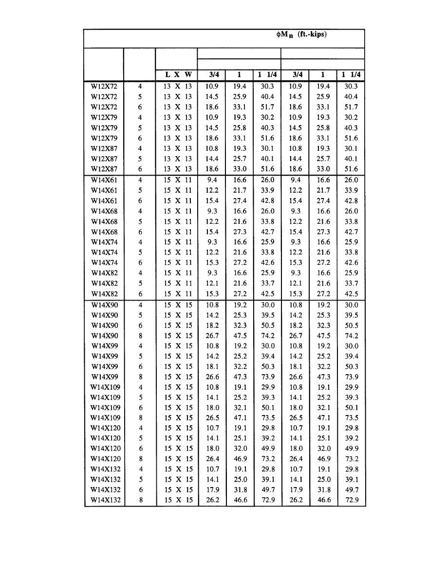
Table A-2 Moment Resistance of Base Plates with
Inset Anchor Rods Based on Plate Strength
65
BASE PLATE BENDING RESISTANCE,
WITH INSET ANCHOR RODS
Shape
Anchor
Rod
Spacing
Base Plate
Plan Size
X-X Axis
Plate Thickness
Y-Y Axis
Plate Thickness
© 2003 by American Institute of Steel Construction, Inc. All rights reserved.
This publication or any part thereof must not be reproduced in any form without permission of the publisher.
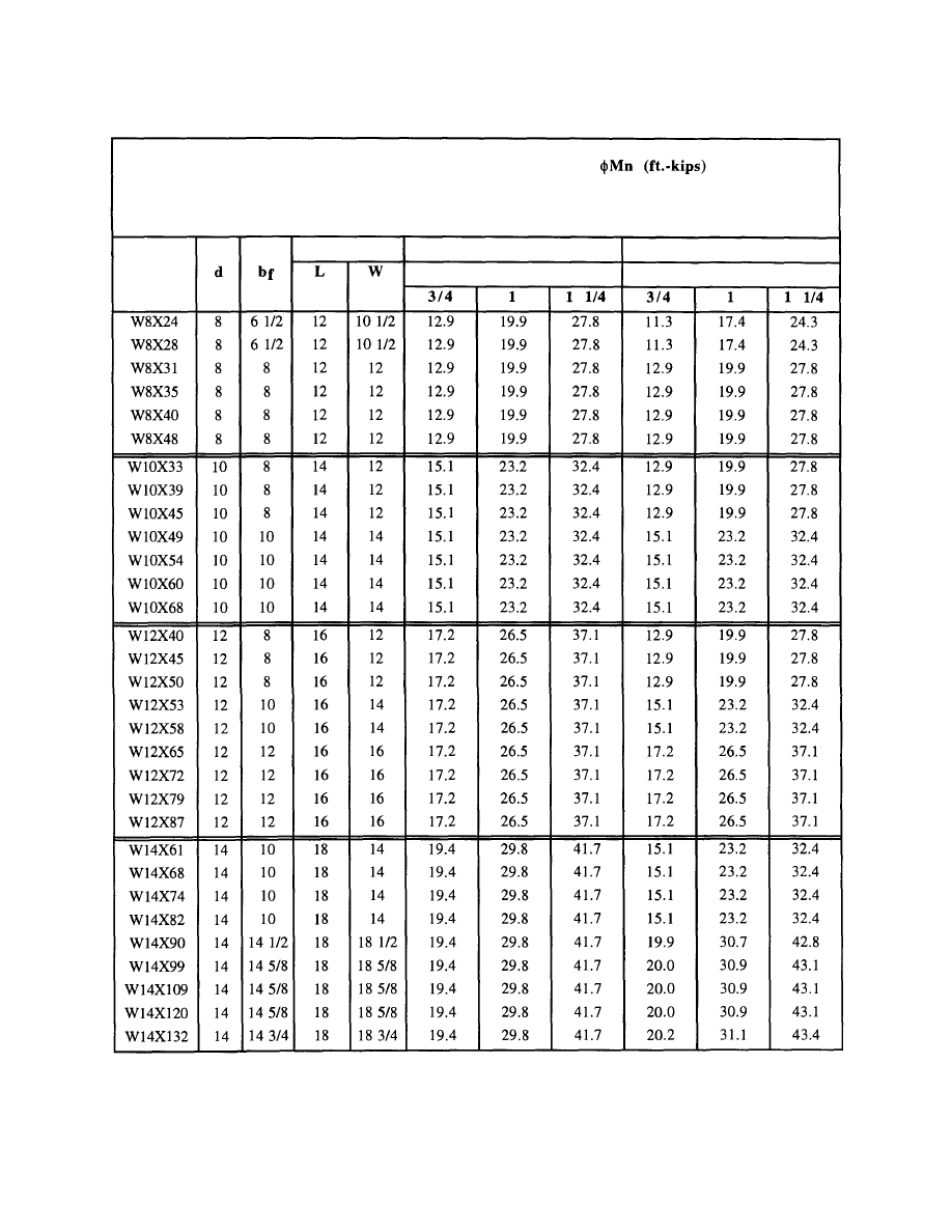
Table A-3 Moment Resistance of Base Plates with
Outset Anchor Rods
66
MOMENT RESISTANCE - OUTSET RODS,
5/16 inch fillet welds
E70XX Electrode
Shape
Rod Pattern
X-X Axis
Plate Thickness
Y-Y Axis
Plate Thickness
© 2003 by American Institute of Steel Construction, Inc. All rights reserved.
This publication or any part thereof must not be reproduced in any form without permission of the publisher.
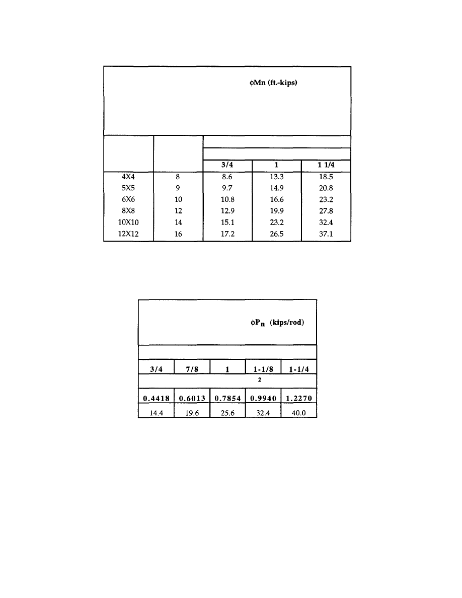
MOMENT RESISTANCE,
Nominal
TS
Size
Anchor
Rod
Spacing
X-X or Y-Y Axis
Plate Thickness
Table A-4 Moment Resistance of Tube Column Base Plates
TENSION RESISTANCE,
Single A36 Anchor Rods
Rod Diameter, in.
Tension Area, in.
Table A-5 Tension Resistance of Anchor Rods Based
on Anchor Rod Strength
67
TUBE COLUMN BASE PLATE
5/16 inch fillet welds
E70XX Electrode
© 2003 by American Institute of Steel Construction, Inc. All rights reserved.
This publication or any part thereof must not be reproduced in any form without permission of the publisher.
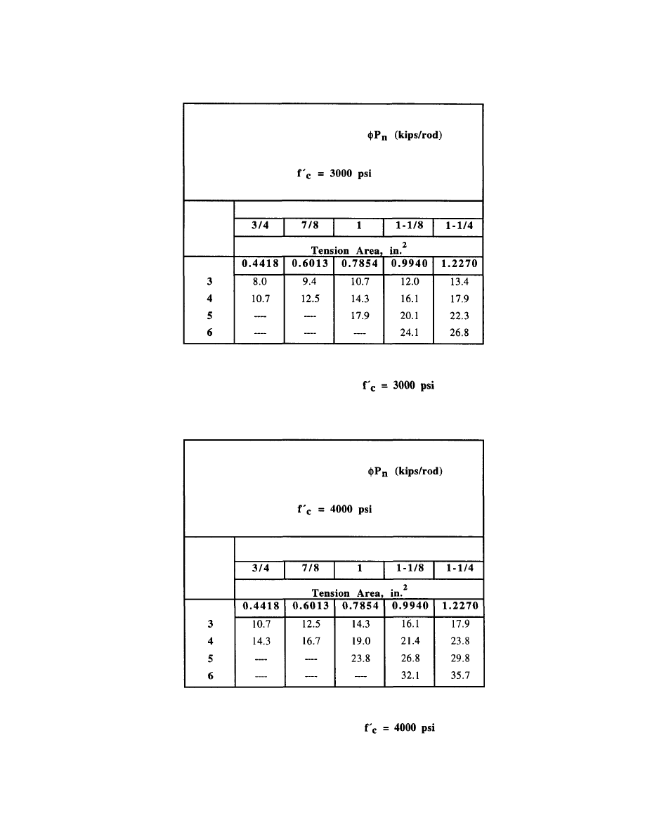
Table A-7 Tension Resistance of Hooked Anchor Rods
Based on Hook Length,
68
TENSION RESISTANCE,
Single A36 Hooked Anchor Rods
Rod Diameter, in.
Hook
Length
in.
Table A-6 Tension Resistance of Hooked Anchor Rods
Based on Hook Length,
TENSION RESISTANCE,
Single A36 Hooked Anchor Rods
Hook
Length
in.
Rod Diameter, in.
© 2003 by American Institute of Steel Construction, Inc. All rights reserved.
This publication or any part thereof must not be reproduced in any form without permission of the publisher.
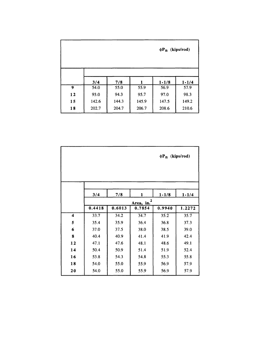
CONCRETE PULL OUT RESISTANCE,
Single Nutted Anchor Rods
Embed.
Depth
Anchor Rod Diameter, in.
Table A-8 Tension Resistance of Single Anchor Rods
Based on Concrete Pull Out Capacity
Table A-9 Tension Resistance of Two Anchor Rods
Based on Spacing and Embedment
69
CONCRETE PULL OUT RESISTANCE,
Anchor Rods in Groups
Embedment Depth = 9 inches
Anchor
Rod
Spacing
in.
Anchor Rod Diameter, in.
© 2003 by American Institute of Steel Construction, Inc. All rights reserved.
This publication or any part thereof must not be reproduced in any form without permission of the publisher.
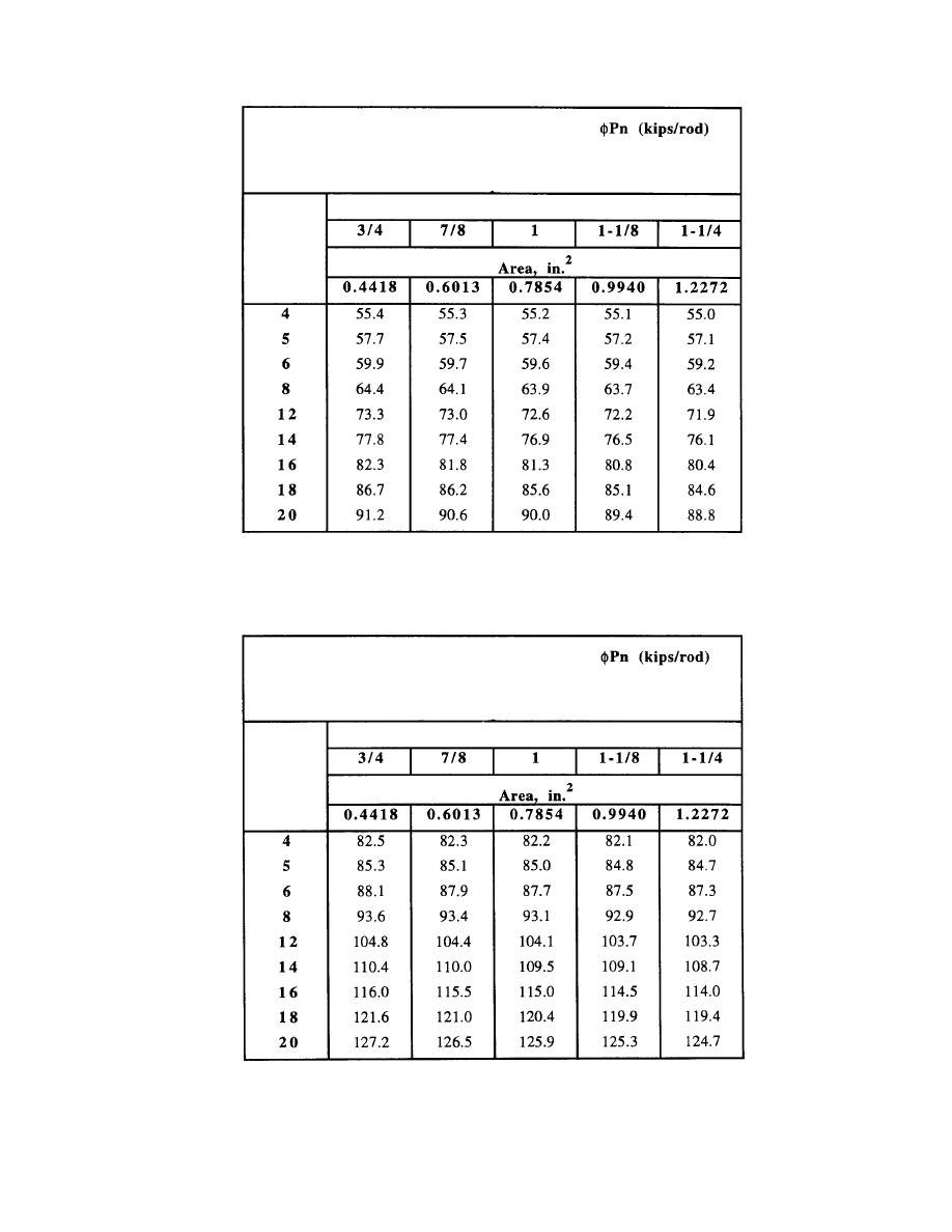
Table A-11 Tension Resistance of Two Anchor Rods Based
on Spacing and Embedment
70
CONCRETE PULL OUT RESISTANCE,
Anchor Rods in Groups
Embedment Depth = 15 inches
Anchor
Rod
Spacing
in.
Anchor Rod Diameter, in.
Table A-10
Tension Resistance of Two Anchor Rods Based
on Spacing and Embedment
CONCRETE PULL OUT RESISTANCE,
Anchor Rods in Groups
Embedment Depth = 12 inches
Anchor
Rod
Spacing
i n .
Anchor Rod Diameter, in.
© 2003 by American Institute of Steel Construction, Inc. All rights reserved.
This publication or any part thereof must not be reproduced in any form without permission of the publisher.
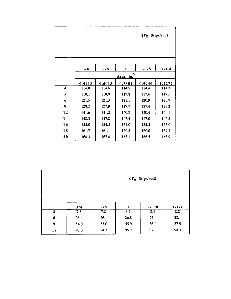
Table A-13 Compression Resistance of Single Anchor
Rods Based on Concrete Push Out
71
PUSH OUT RESISTANCE,
Single Anchor Rods
Anchor Rod Diameter, in.
Clear
Cover, in.
Table A-12 Tension Resistance of Two Anchor Rods Based
on Spacing and Embedment
CONCRETE PULL OUT RESISTANCE,
Anchor Rods in Groups
Embedment Depth = 18 inches
Anchor
Rod
Spacing
in.
Anchor Rod Diameter, in.
© 2003 by American Institute of Steel Construction, Inc. All rights reserved.
This publication or any part thereof must not be reproduced in any form without permission of the publisher.
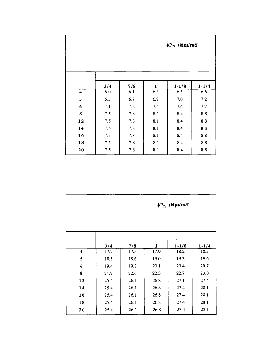
Table A-15
Compression Resistance of Two Anchor Rods
Based on Concrete Push Out
72
Anchor Rod
Spacing, in.
Anchor Rod Diameter, in.
PUSH OUT RESISTANCE,
Group of Two Anchor Rods
Clear Cover = 6 inches
Table A-14
Compression Resistance of Two Anchor
Rods Based on Concrete Push Out
PUSH OUT SHEAR RESISTANCE,
Group of Two Anchor Rods
Clear Cover = 3 inches
Anchor Rod
Spacing, in.
Anchor Rod Diameter, in.
© 2003 by American Institute of Steel Construction, Inc. All rights reserved.
This publication or any part thereof must not be reproduced in any form without permission of the publisher.
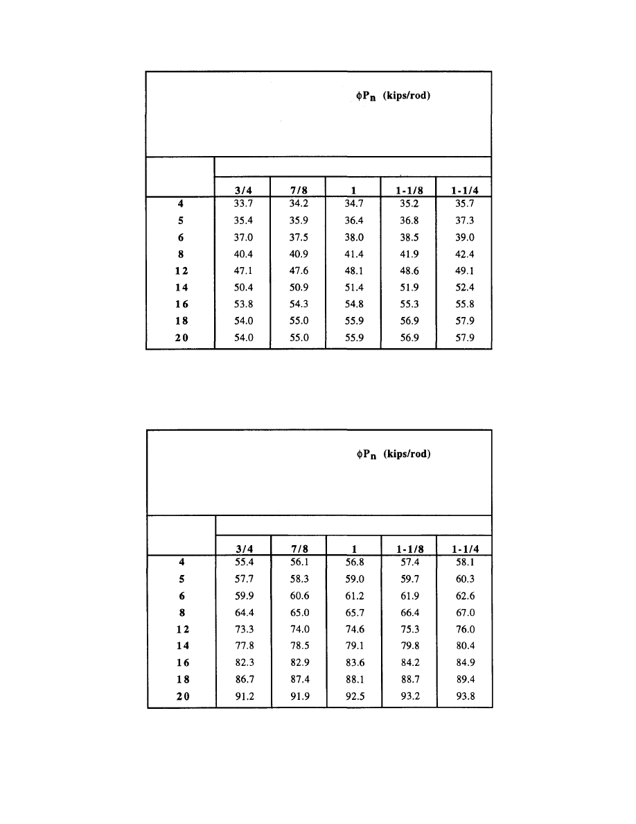
Table A-17
Compression Resistance of Two Anchor Rods
Based on Concrete Push Out
73
PUSH OUT RESISTANCE,
Group of Two Anchor Rods
Clear Cover = 12 inches
Anchor Rod
Spacing, in.
Anchor Rod Diameter, in.
Table A-16 Compression Resistance of Two Anchor Rods
Based on Concrete Push Out
PUSH OUT RESISTANCE,
Group of Two Anchor Rods
Clear Cover = 9 inches
Anchor Rod
Spacing, in.
Anchor Rod Diameter, in.
© 2003 by American Institute of Steel Construction, Inc. All rights reserved.
This publication or any part thereof must not be reproduced in any form without permission of the publisher.
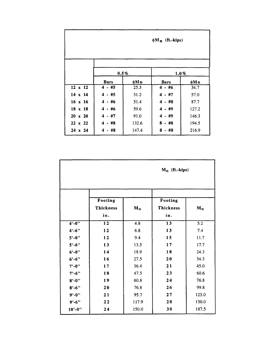
BENDING RESISTANCE,
Single Square Piers
Reinforcing
Size, in.
Table A-18
Concrete Pier Bending Resistance
Table A-19 Concrete Footing Overturning Resistance
74
OVERTURNING RESISTANCE,
Single Square Footings
Size
Thickness Group A
Thickness Group B
© 2003 by American Institute of Steel Construction, Inc. All rights reserved.
This publication or any part thereof must not be reproduced in any form without permission of the publisher.
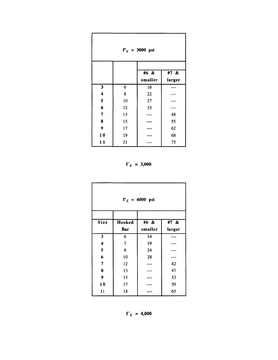
Table A-20 Reinforcing Bar Development Lengths,
Table A-21 Reinforcing Bar Development Lengths,
75
Required Development Length (inches)
Bar
Standard
Straight bars
Required Development Length (inches)
Bar
Size
Standard
Hooked
Bar
Straight bars
© 2003 by American Institute of Steel Construction, Inc. All rights reserved.
This publication or any part thereof must not be reproduced in any form without permission of the publisher.
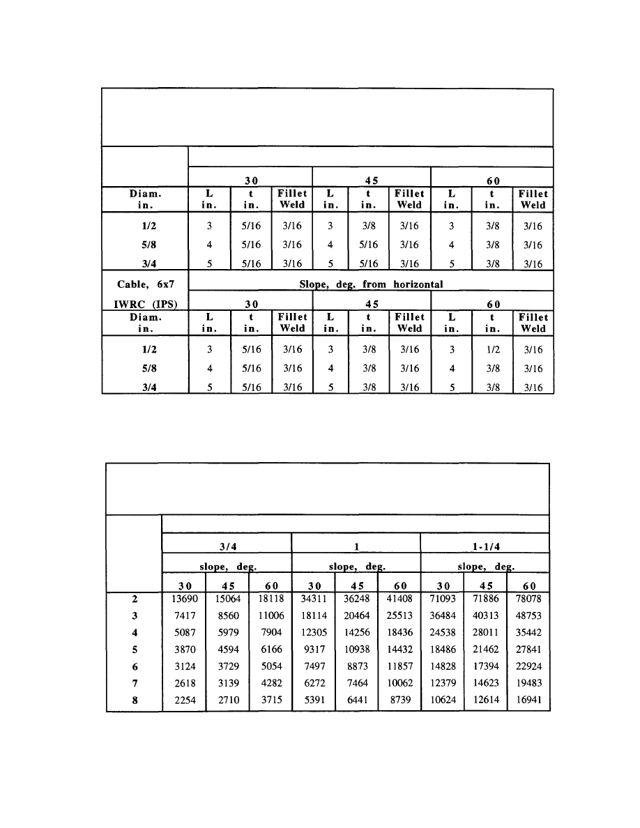
Table A-23
Allowable Cable Force, Type A Plate Anchor
as Limited by Anchor Rod Capacity
76
PLATE ANCHOR
ALLOWABLE CABLE FORCE, P (lbs.)
Anchor Rods in Tension & Bending
Grout
Depth
i n .
Anchor Rod Diameter, in.
Table A-22
Dimensions of Type A Anchor Plates and Welds
PLATE ANCHOR - TYPE A
Plate in Tension & Bending
Slope, deg. from horizontal
Cable, 6x7
FC (IPS)
© 2003 by American Institute of Steel Construction, Inc. All rights reserved.
This publication or any part thereof must not be reproduced in any form without permission of the publisher.
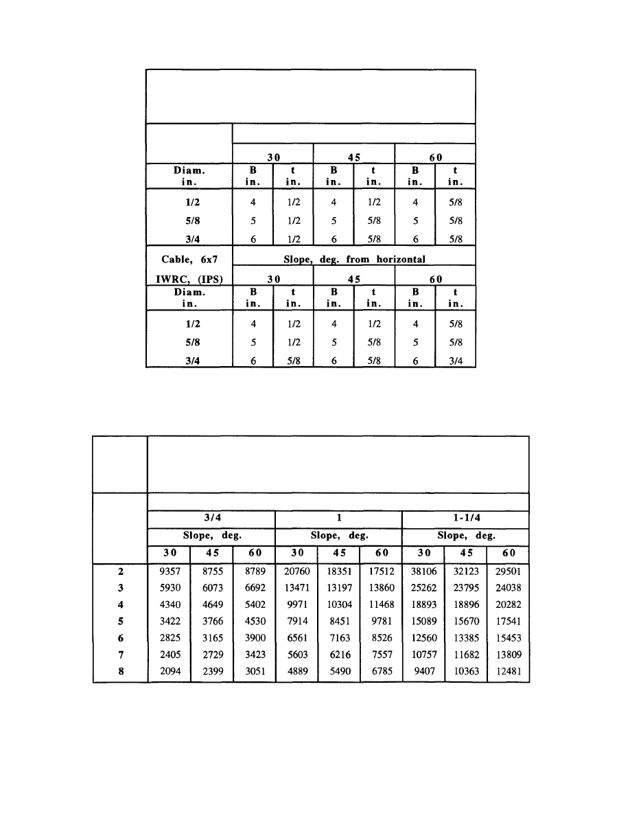
Table A-25 Allowable Cable Force, Type B Plate
Anchor as Limited by Anchor Rod Capacity
77
BENT PLATE ANCHOR
ALLOWABLE CABLE FORCE, P (lbs.)
Anchor Rods in Tension & Bending
Grout
Depth
i n .
Anchor Rod Diameter, in.
Table A-24 Dimensions of Type B Anchor Plate and Welds
BENT PLATE ANCHOR - TYPE B
Plate in Tension & Bending
Cable, 6x7
FC, (IPS)
Slope, deg. from horizontal
© 2003 by American Institute of Steel Construction, Inc. All rights reserved.
This publication or any part thereof must not be reproduced in any form without permission of the publisher.

NOTES:
© 2003 by American Institute of Steel Construction, Inc. All rights reserved.
This publication or any part thereof must not be reproduced in any form without permission of the publisher.

DESIGN GUIDE SERIES
American Institute of Steel Construction, Inc.
One East Wacker Drive, Suite 3100
Chicago, Illinois 60601-2001
Pub. No. D 8 1 0 (5M597)
© 2003 by American Institute of Steel Construction, Inc. All rights reserved.
This publication or any part thereof must not be reproduced in any form without permission of the publisher.
Wyszukiwarka
Podobne podstrony:
Design Guide 17 High Strength Bolts A Primer for Structural Engineers
Design Guide 05 Design of Low and Medium Rise Steel Buildings
Design Guide 03 Serviceability Design Considerations for Low Rise Buildings
Design Guide 02 Design of Steel and Composite Beams with Web Openings
Design Guide 12 Modification of Existing Steel Welded Moment Frame
Design Guide 06 LRFD of W Shapes Encased in Concrete
(10)Bactericidal Effect of Silver Nanoparticles
ESL Seminars Preparation Guide For The Test of Spoken Engl
Design Guide 20 Steel Plate Shear Walls
DESIGN, SIMULATION, AND TEST RESULTS OF A HEAT ASSISTED THREE CYLINDER STIRLING HEAT PUMP (C 3)(1)
Vladimir Lenin Analysis of his Rise to Power
Longman Portfolio Guide 6 10
10 In the?ve of?ullam Pink
IP Telephony Design Guide Alcatel
Progress Database Design Guide
Quantitative dilatometric analysis of intercritical annealing in a low silicon TRIP steel
Cold Space Vehicle Design Guide
Design Guide 14 Staggered Truss Framing Systems
więcej podobnych podstron