
TK-7102H
INSTRUCTION MANUAL
VHF FM TRANSCEIVER
© B62-1596-00 (M)
09 08 07 06 05 04 03 02 01 00
KENWOOD CORPORATION
TK-8102H
UHF FM TRANSCEIVER


i
THANK YOU!
We are grateful you chose KENWOOD for your personal mobile applications. We believe this
easy-to-use transceiver will provide dependable communications to keep personnel operating
at peak efficiency.
KENWOOD transceivers incorporate the latest in advanced technology. As a result, we feel
strongly that you will be pleased with the quality and features of this product.
MODELS COVERED BY THIS MANUAL
The models listed below are covered by this manual:
• TK-7102H:
VHF FM Transceiver
• TK-8102H:
UHF FM Transceiver
NOTICES TO THE USER
◆
Government law prohibits the operation of unlicensed transmitters within the territories under
government control.
◆
Illegal operation is punishable by fine and/or imprisonment.
◆
Refer service to qualified technicians only.
SAFETY: It is important that the operator is aware of, and understands, hazards
common to the operation of any transceiver.
◆
EXPLOSIVE ATMOSPHERES (GASES, DUST, FUMES, etc.)
Turn OFF your transceiver while taking on fuel or while parked in gasoline service stations. Do not
carry spare fuel containers in the trunk of your vehicle if your transceiver is mounted in the trunk area.
◆
INJURY FROM RADIO FREQUENCY TRANSMISSIONS
Do not operate your transceiver when somebody is either touching the antenna or standing within
two to three feet of it, to avoid the possibility of radio frequency burns or related physical injury.
◆
DYNAMITE BLASTING CAPS
Operating the transceiver within 500 feet (150 m) of dynamite blasting caps may cause them to
explode. Turn OFF your transceiver when in an area where blasting is in progress, or where
“TURN OFF TWO-WAY RADIO” signs have been posted. If you are transporting blasting caps in
your vehicle, make sure they are carried in a closed metal box with a padded interior. Do not
transmit while the caps are being placed into or removed from the container.
PRECAUTIONS
Please observe the following precautions to prevent fire, personal injury, and transceiver
damage.
• Do not attempt to configure the transceiver while driving; it is too dangerous.
• Do not modify the transceiver for any reason.
• Do not expose the transceiver to long periods of direct sunlight, nor place it near heating
appliances.
• Do not place the transceiver in excessively dusty, humid, or wet areas, nor on unstable surfaces.
• If an abnormal odor or smoke is detected coming from the transceiver, turn OFF the power
immediately. Contact your KENWOOD dealer.

ii
CONTENTS
UNPACKING AND CHECKING EQUIPMENT ................................... 1
S
UPPLIED
A
CCESSORIES
..................................................................... 1
PREPARATION .................................................................................. 2
T
OOLS
R
EQUIRED
.............................................................................. 2
P
OWER
C
ABLE
C
ONNECTION
............................................................... 2
I
NSTALLING
THE
T
RANSCEIVER
.............................................................. 3
ORIENTATION .................................................................................... 4
F
RONT
P
ANEL
................................................................................... 4
D
ISPLAY
............................................................................................ 5
R
EAR
P
ANEL
..................................................................................... 5
BASIC OPERATIONS ........................................................................ 6
S
WITCHING
P
OWER
ON/ OFF ............................................................. 6
A
DJUSTING
THE
V
OLUME
..................................................................... 6
S
ELECTING
A
C
HANNEL
....................................................................... 6
T
RANSMITTING
................................................................................... 6
R
ECEIVING
........................................................................................ 6
SCAN .................................................................................................. 7
T
EMPORARY
D
ELETE
.......................................................................... 7
R
EVERT
C
HANNEL
.............................................................................. 7
DTMF CALLS ..................................................................................... 8
M
ANUAL
D
IALLING
............................................................................. 8
S
TORING
DTMF N
UMBERS
................................................................. 8
D
IALLING
S
TORED
DTMF N
UMBERS
.................................................... 8
C
LEARING
S
TORED
DTMF N
UMBERS
................................................... 8
R
EDIALLING
....................................................................................... 8
CODE SQUELCH (ID CODE) ............................................................ 9
R
ECEIVING
........................................................................................ 9
T
RANSMITTING
................................................................................... 9
ADVANCED OPERATIONS ............................................................. 10
T
IME
-
OUT
T
IMER
(TOT) .................................................................... 10
B
USY
C
HANNEL
L
OCKOUT
(BCL) ...................................................... 10
T
ALK
-A
ROUND
................................................................................. 10
M
ONITOR
........................................................................................ 10
E
MERGENCY
O
PERATION
................................................................... 11
K
EY
L
OCK
...................................................................................... 11
B
EGINNING
/ E
ND
OF
T
RANSMISSION
ID S
IGNAL
.................................... 11
1
UNPACKING AND CHECKING EQUIPMENT
Note: The following unpacking instructions are for use by your KENWOOD dealer, an authorized
KENWOOD service facility, or the factory.
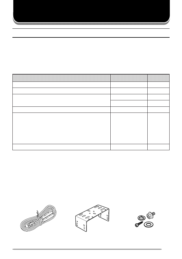
Carefully unpack the transceiver. We recommend that you identify the items
listed in the following table before discarding the packing material. If any items
are missing or have been damaged during shipment, file a claim with the carrier
immediately.
S
UPPLIED
A
CCESSORIES
m
e
t
I
r
e
b
m
u
N
t
r
a
P
y
t
i
t
n
a
u
Q
e
n
o
h
p
o
r
c
i
M
X
X
-
4
2
6
0
-
1
9
T
1
r
e
d
l
o
h
e
n
o
h
p
o
r
c
i
M
X
X
-
4
8
5
1
-
9
1
J
1
e
l
b
a
c
r
e
w
o
p
C
D
X
X
-
9
3
3
3
-
0
3
E
1
)
A
5
1
(
e
s
u
F
•
X
X
-
7
1
0
0
-
1
5
F
2
t
e
k
c
a
r
b
g
n
i
t
n
u
o
M
X
X
-
2
6
6
0
-
9
2
J
1
:
t
e
s
w
e
r
c
S
X
X
-
5
9
3
0
-
9
9
N
1
)
s
e
c
e
i
p
4
(
w
e
r
c
s
g
n
i
p
p
a
t
-
f
l
e
S
•
)
s
e
c
e
i
p
4
(
r
e
h
s
a
w
h
t
i
w
w
e
r
c
s
d
e
d
a
e
h
-
x
e
H
•
)
s
e
c
e
i
p
4
(
r
e
h
s
a
w
g
n
i
r
p
S
•
)
s
e
c
e
i
p
4
(
r
e
h
s
a
w
t
a
l
F
•
l
a
u
n
a
m
n
o
i
t
c
u
r
t
s
n
I
X
X
-
6
9
5
1
-
2
6
B
1
DC power cable
with fuses
Mounting bracket
Screw set
Microphone
Microphone holder

2
Various electronic equipment in your vehicle may malfunction if they are not properly protected from
the radio frequency energy which is present while transmitting. Electronic fuel injection, anti-skid
braking, and cruise control systems are typical examples of equipment that may malfunction. If your
vehicle contains such equipment, consult the dealer for the make of vehicle and enlist his/her aid in
determining if they will perform normally while transmitting.
Note: The following preparation instructions are for use by your KENWOOD dealer, an authorized
KENWOOD service facility, or the factory.
T
OOLS
R
EQUIRED
Note: Before installing the transceiver, always check how far the mounting screws will extend below
the mounting surface. When drilling mounting holes, be careful not to damage vehicle wiring or parts.
The following tools are required for installing the transceiver:
• 6 mm (1/4 inch) or larger electric drill
• 4.2 mm (5/32 inch) drill bit for the self-tapping screws
• Circle cutters
P
OWER
C
ABLE
C
ONNECTION
The transceiver operates in 12 V negative ground systems only! Check the battery polarity and
voltage of the vehicle before installing the transceiver.
1 Check for an existing hole, conveniently located in the firewall, where the
power cable can be passed through.
• If no hole exists, use a circle cutter to drill the firewall, then install a rubber
grommet.
2 Run the two power cable leads through the firewall and into the engine
compartment, from the passenger compartment.
3 Connect the red lead to the positive (+) battery terminal and the black lead to
the negative (–) battery terminal.
• Locate the fuse as close to the battery as possible.
4 Coil and secure the surplus cable with a retaining band.
• Be sure to leave enough slack in the cables so the transceiver can be removed for
servicing while keeping the power applied.
PREPARATION
3
I
NSTALLING
THE
T
RANSCEIVER
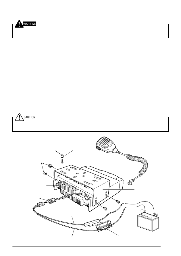
For passenger safety, install the transceiver securely, using the supplied mounting bracket, so the
transceiver will not break loose in the event of a collision.
1 Mark the position of the holes in the dash by using the mounting bracket as a
template. Drill the holes, then attach the mounting bracket using the supplied
self-tapping screws.
• Be sure to mount the transceiver in a location where the controls are within easy
reach of the user and where there is sufficient space at the rear of the transceiver
for cable connections.
2 Connect the antenna and the supplied power cable to the transceiver.
3 Slide the transceiver into the mounting bracket and secure it using the
supplied hex-headed screws.
4 Mount the microphone hanger in a location where it will be within easy reach
of the user.
• The microphone and microphone cable should be mounted in a place where they
will not interfere with the safe operation of the vehicle.
When replacing the fuse in the DC power cable, be sure to replace it with a fuse of the same value.
Never replace a fuse with a fuse that has a higher value.
Hex-headed
screws
DC power cable
Mounting bracket
Antenna
connector
Power input
connector
Fuse
Black cable
Red cable
12 V vehicle
battery
Microphone
Self-tapping screw
Spring
washer
Flat washer
4
ORIENTATION
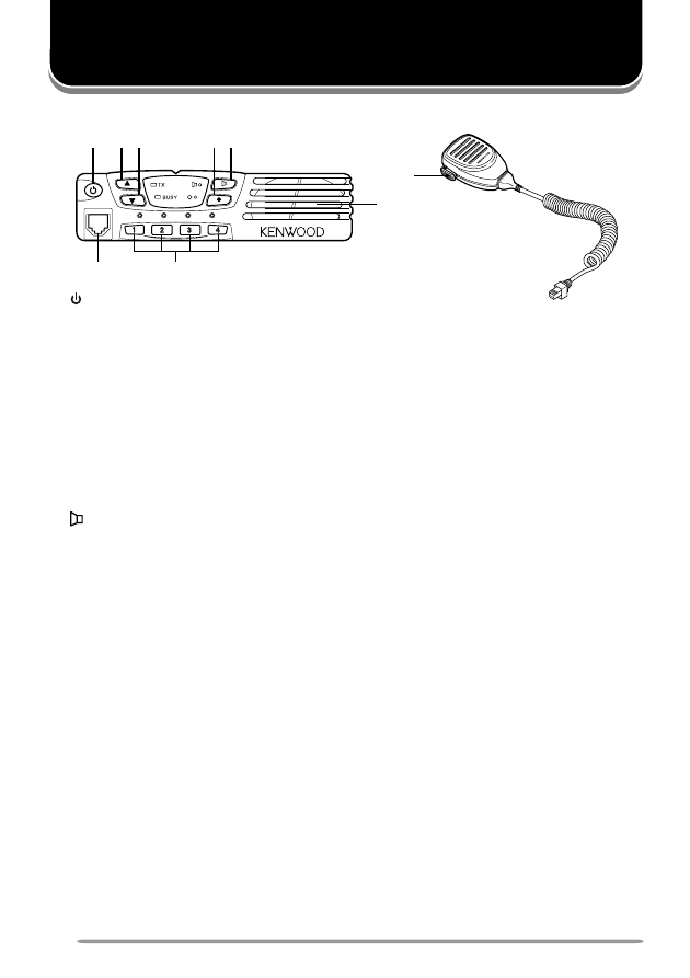
F
RONT
P
ANEL
q
q
q
q
q
(Power) switch
Press to switch the transceiver ON. Press and hold for approximately
1 second to switch the transceiver OFF.
w
w
w
w
w
▲
key
Press to increase the volume level.
e
e
e
e
e
▼
key
Press to decrease the volume level.
r
r
r
r
r
●
key
PF (Programmable Function) key. The default setting of this key is None (no
function). The programmable functions available for this key are listed below.
t
t
t
t
t
key
PF (Programmable Function) key. The default setting of this key is Monitor
(page 10). Other programmable functions available for this key are listed below.
y
y
y
y
y
1 / 2 / 3 / 4 keys
Press to select a channel from 1 to 4.
u
u
u
u
u
Microphone jack
Insert the microphone plug into this jack (the microphone is an optional
accessory).
i
i
i
i
i
Speaker
Internal speaker.
o
o
o
o
o
PTT switch
Press this switch, then speak into the microphone to call a station.
Auxiliary Programmable Functions:
• Emergency
• Scan On/ Off
• Key Lock
• Talk Around
• Monitor
• Temporary Delete
• None (no function)
q
w e
t
r
y
u
i
o
5
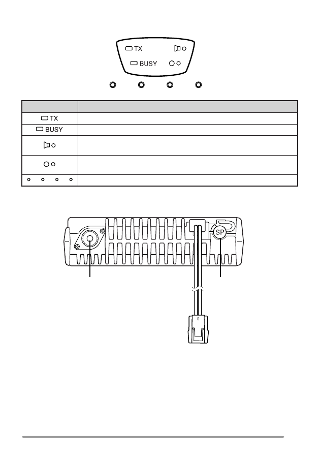
D
ISPLAY
R
EAR
P
ANEL
External
speaker jack
Power input
connector
Antenna connector
r
o
t
a
c
i
d
n
I
n
o
i
t
p
i
r
c
s
e
D
.
g
n
i
t
t
i
m
s
n
a
r
t
e
li
h
w
s
t
h
g
i
L
.
l
e
n
n
a
h
c
d
e
t
c
e
l
e
s
y
l
t
n
e
r
r
u
c
e
h
t
n
o
d
e
t
c
e
t
e
d
s
i
l
a
n
g
i
s
a
n
e
h
w
s
t
h
g
i
L
s
i
y
e
k
g
n
i
d
n
o
p
s
e
r
r
o
c
s
t
i
o
t
n
o
d
e
m
m
a
r
g
o
r
p
n
o
i
t
c
n
u
f
e
h
t
e
li
h
w
s
t
h
g
i
L
.
d
e
t
a
v
i
t
c
a
s
i
y
e
k
g
n
i
d
n
o
p
s
e
r
r
o
c
s
t
i
o
t
n
o
d
e
m
m
a
r
g
o
r
p
n
o
i
t
c
n
u
f
e
h
t
e
li
h
w
s
t
h
g
i
L
.
d
e
t
a
v
i
t
c
a
.
)
4
~
1
(
l
e
n
n
a
h
c
d
e
t
c
e
l
e
s
y
l
t
n
e
r
r
u
c
e
h
t
y
a
l
p
s
i
d
o
t
s
t
h
g
i
L

6
BASIC OPERATIONS
S
WITCHING
P
OWER
ON/ OFF
Press the switch to switch the transceiver ON.
Press and hold the switch for approximately 1 second to switch the
transceiver OFF.
A
DJUSTING
THE
V
OLUME
Press the
▲
key to increase the volume and the
▼
key to decrease the volume.
S
ELECTING
A
C
HANNEL
Select your desired channel by pressing a key from 1 to 4.
T
RANSMITTING
Note: Before transmitting, first monitor the channel to make sure it is not already in use.
1 Select your desired channel by pressing a channel key (1 ~ 4).
• If the channel is busy, wait until it becomes free.
2 Press the microphone PTT switch and speak into the microphone. Release
the PTT switch when you have finished speaking.
• For best sound quality at the receiving station, hold the microphone approximately
1.5 inches (3 ~ 4 cm) from your mouth.
R
ECEIVING
1 Select your desired channel by pressing a channel key (1 ~ 4).
2 When you hear a signal, readjust the volume level if necessary.
3 Respond to the call as described in step 2 of “T
RANSMITTING
”, above.

7
SCAN
To activate the Scan function, press the key programmed as Scan On/ Off.
• The indicator next to the programmed key flashes (“
” or “
”).
When a signal is detected on a channel, the Scan indicator stops flashing. At
this time, both the Scan indicator and the Busy indicator light.
When the signal is no longer present, Scan resumes and the Scan indicator
flashes again.
To stop scanning, press the Scan On/ Off key again.
• The transceiver returns to the channel that was selected before Scan started.
T
EMPORARY
D
ELETE
Depending on how your transceiver has been set up, a key may have been
programmed with the Temporary Delete function. If so, press and hold that
programmed key for approximately 1 second to temporarily remove undesired
channels from the scanning sequence. This allows you to scan only those
channels which you desire. After switching the Scan function OFF, or switching
the transceiver OFF and then ON again, the Scan settings return to normal.
Note: In order for Scan to function, there must be at least 2 channels added to the scanning
sequence. If there are less channels than this, Scan does not operate.
R
EVERT
C
HANNEL
During Scan, pressing the PTT switch to transmit will cause the transceiver to
select the revert channel. Your dealer programs the Revert channel for your
transceiver. Consult your dealer for details.

8
DTMF CALLS
Note: To make DTMF calls, you must have an optional microphone with a DTMF keypad.
M
ANUAL
D
IALLING
Press and hold the PTT switch, then enter the digits on the microphone keypad.
• You can enter the digits 0 ~ 9, A ~ D,
, and #. (A ~ D may be disabled by your dealer.)
• If programmed by your dealer, you do not need to continuously hold the PTT switch;
the transceiver will remain in the transmit state for 2 seconds after releasing each key.
• While transmitting DTMF tones, the microphone is muted.
S
TORING
DTMF N
UMBERS
If Auto Dialling has been activated by your dealer, you can store DTMF numbers
(16 digits maximum) in each of the 9 Auto Dial memory locations (1 ~ 9).
1 Press the microphone # key.
2 Enter the desired digits on the microphone keypad.
• You can enter the digits 0 ~ 9, A ~ D,
, and #.
• When entering “#”, you must first press the PTT switch.
• To cancel, press any key on the transceiver front panel, other than the switch.
3 Press the microphone # key, then enter a memory location number (1 ~ 9).
• If no key is pressed within 10 seconds, the transceiver will return to normal operation.
D
IALLING
S
TORED
DTMF N
UMBERS
1 Press the microphone
key.
2 Enter the desired memory location number (1 ~ 9).
3 Press the PTT switch.
• If programmed by your dealer, no DTMF tone will sound when “D” is transmitted.
“D” is used for a pause time. The pause duration is programmed by your dealer.
C
LEARING
S
TORED
DTMF N
UMBERS
1 Press the microphone # key twice.
• To cancel the process, press any key other than 1 ~ 9.
2 Enter the desired memory location number (1 ~ 9).
R
EDIALLING
1 Press the microphone
key, then press the 0 key.
2 Press the PTT switch.
Note: Switching the transceiver power OFF clears the redial memory.

9
CODE SQUELCH (ID CODE)
Code Squelch is enabled or disabled by your dealer. This function turns the
transceiver squelch OFF only when it receives the DTMF code that has been set
up in your transceiver. Transceivers that do not transmit the correct code will not
be heard. Consequently, you can communicate with a specific party without
listening to other parties using the same channel.
Your dealer may also activate Group Call for your transceiver. This is useful
when you want to send information to a number of units in a fleet. Ask your
dealer for details.
R
ECEIVING
When you receive a signal containing the correct code, Code Squelch turns OFF
and you will hear the call.
• To mute the speaker after Code Squelch turns OFF, press the key programmed as
Monitor.
• Your dealer can program Code Squelch to automatically turn back ON after a specific
time period elapses.
• If Transpond is programmed, an acknowledgment signal is returned to the calling
station. Transpond does not function when you are called with a Group code.
Transpond can send an alert tone or a transceiver ID code.
• If Call Alert is programmed, an alert tone will sound when the correct code is received.
T
RANSMITTING
1 Press and hold the PTT switch.
2 Enter the code of the transceiver you want to call or enter a Group code on
the microphone keypad.
• If desired, you can send codes the same way you make DTMF calls {page 8}.
3 Use the transceiver the same as in a regular call; press the PTT switch to
transmit and release it to receive.
• The called transceiver’s Code Squelch will turn OFF while you are transmitting.
After you stop transmitting, the Code Squelch will turn back ON after a pre-set time
period elapses. This time period is programmed by your dealer.
• When you release the PTT switch, Code Squelch turns OFF. If no signal is
received for a pre-determined time, Code Squelch turns back ON.
• Pressing the key programmed as Monitor at any time will turn the Code Squelch
back ON.

10
ADVANCED OPERATIONS
T
IME
-
OUT
T
IMER
(TOT)
The purpose of the Time-out Timer is to prevent any caller from using a channel
for an extended period of time. If you continuously transmit for a period of time
that exceeds the programmed time, the transceiver will stop transmitting and an
alert tone will sound. To stop the tone, release the PTT switch.
Your dealer can program a warning function to alert you before the TOT expires.
Continuously transmitting for the time specified by your dealer will cause the
warning tone to sound.
B
USY
C
HANNEL
L
OCKOUT
(BCL)
The Busy Channel Lockout feature is activated or deactivated by your dealer.
When activated, BCL prevents you from interfering with other parties who may be
using the same channel that you selected. Pressing the PTT switch while the
channel is in use will cause your transceiver to emit an alert tone and
transmission will be inhibited (you cannot transmit). Release the PTT switch to
stop the tone and return to receive mode.
T
ALK
A
ROUND
You may occasionally experience an interruption in service (due to a power
failure, etc.). During such an occurence, you can continue communication by
using the Talk Around feature, if it has been programmed by your dealer.
Talk Around allows you to communicate directly with other transceivers, without
the use of a repeater. However, if the station you want to contact is too far away,
or there are geographical obstacles in the way, you may not be able to contact
the station.
Toggle Talk Around ON and OFF by pressing the key programmed as Talk Around.
• The indicator corresponding to the Talk Around key lights while the Talk Around function is ON.
• When using Talk Around, the “receive” frequency is used for both transmission and
reception, and the QT/DQT “decode” signalling is used for both encoding and decoding.
M
ONITOR
Press the key programmed as Monitor to turn the transceiver signalling OFF.
While signalling is OFF, you can hear all signals received on your current
channel. With signalling ON, you can hear only signals that match the signalling
programmed in your transceiver. Press the Monitor key again to return to
normal operation.
Press and hold the key programmed as Monitor for 2 seconds to listen to weak
signals that you cannot hear during normal operation, and to adjust the volume
when no signals are present on your selected channel. Press the Monitor key
again to return to normal operation.

11
E
MERGENCY
O
PERATION
There are two Emergency Operation modes: Emergency Operation 1 and
Emergency Operation 2.
Press and hold the key programmed as Emergency to enter Emergency
Operation 1.
• The transceiver will beep unless your dealer has activated “Secret” Emergency
Operation 1.
• The channel will switch to the pre-programmed emergency channel.
While in “Secret” Emergency Operation 1, the Busy indicator lights every
10 seconds, indicating that you are in Emergency Operation 1. When your signal
has been acknowledged, the Busy indicator will light 2 times every 10 seconds.
Press and hold the Emergency key again to enter Emergency Operation 2.
• The transceiver will beep unless your dealer has activated “Secret” Emergency
Operation 2.
While in “Secret” Emergency Operation 2, the transceiver will wait for 1 minute,
then activate the function attached to its control function port. This could be your
car horn or headlights. When the transceiver receives an Emergency Reset
code, it will return to normal operation. Or, if you press and hold the Emergency
key for more than 10 seconds, you can return the transceiver to normal
operation.
If enabled by your dealer, the transceiver can continue Emergency Operation
even while the transceiver power is OFF.
K
EY
L
OCK
Press the key programmed as Key Lock to lock the keys of the transceiver.
Locking the transceiver keys prevents you from accidentally changing the
channel and channel settings. While key lock is active, you can still use the
microphone PTT switch, the (power) switch, and the Emergency, Monitor,
▲
,
and
▼
keys.
Press the Key Lock key again to turn this function OFF.
B
EGINNING
/ E
ND
OF
T
RANSMISSION
ID S
IGNAL
Your dealer can enable or disable the Beginning/ End of Transmission
identification signals. These signals are used to access and release some
repeaters and telephone systems.
A Beginning of Transmission ID Signal is sent when you press the PTT switch.
An End of Transmission ID Signal is sent when you release the PTT switch.
Wyszukiwarka
Podobne podstrony:
Kenwood CRS 155 Owners Manual
Kenwood TS 10 Owners Manual
Kenwood AT 300 Owners Manual
Kenwood CD 2260 M Owners Manual 2
Kenwood 103 CD Owners Manual
Kenwood CT 201 Owners Manual
Kenwood 103 AR Owners Manual
Kenwood Basic M 1 D Owners Manual
Kenwood A 907 Owners Manual
Kenwood AS 7 Owners Manual
Kenwood AS 5 Owners Manual
Bmw 01 94 Business Mid Radio Owners Manual
Alpine MRD M300 Mono ampl Owners Manual
MPC The Kit Owners Manual
Oberheim Prommer Owners Manual
Kenwood KDC PS9080R,8080R Manual
Kenwood KRC V879R,779R Manual
Alpine CDM 7874,7872,7871,CDE 7860 Owners Manual
Bmw 01 94 Business Mid Radio Owners Manual
więcej podobnych podstron