
Prommer User's Guide
Table of Contents
1
Oberheim Prommer
MIDI Sampler/
PROM programmer
USER'S GUIDE

Prommer User's Guide
Table of Contents
2

Prommer User's Guide
Table of Contents
3
Oberheim Prommer
User's
Guide
By Paul J. White
Preliminary Edition, June 1986
CAUTION:
To prevent fire or shock hazard, do not expose this appliance to rain or
moisture. Do not remove cover. No user servicable parts inside. Refer
servicing to qualified service personnel.
WARNING:
This equipment generates and uses radio frequency energy and if not
installed and used properly, i.e., in strict accordance with the instruction
manual, may cause harmful interference to radio communications.
Operation of this equipment in a residential area is likely to cause
interference in which case the user at his own expense will be required to
take whatever measures may be required to correct the interference.
© 1986 - Oberheim - A division of ECC Development Corporation
11650 W. Olympic Blvd. , Los Angeles, CA 90064
All rights reserved. Reproduction in whole or in part is prohibited without
permission.
Oberheim, the Oberheim logo, Prommer, Matrix-12, Stretch, DMX, and DX
are trademarks of ECC Development Corporation.
Drumtraks is a trademark of SEQUENTIAL (Sequential Circuits, Inc.)
Simmons is a trademark of Simmons Electronics Limited
LinnDrum and Linn9000 are trademarks of Linn Electronics, Inc.

Prommer User's Guide
Table of Contents
4
TABLE OF CONTENTS
P A G E
1. Introduction
7
2. Getting started
9
3. Blocks
13
A. Select block
B. Block address
C. Block length
D. Protect
4. Sampling
17
A. Sample rate
B. Sample time display
C. Record trigger threshold
D. How to record a sound
5. Playback modes
21
A. Play mode
B. Loop points
C. Looping guidelines
D. Transpose
E. Fine tune
F. Filter frequency
G. External trigger
H. Retrigger delay
I. Emphasis
J. Idle bypass
6. EPROMs
25
A. Cautions
B. Select PROM type
C. PROM offset
D. Check erasure function
E. Erasing EPROMs
F. Compare data function
G. Program PROM function
H. In case of an error...
I. Program linear function
J. Program setup function
K. Load data function
L. Load linear function
M. Load setup function
N. Run program function
O. Example1: Programming EPROM with block of equal size
P. Example 2: Programming multiple EPROMs with one sound
Q. Example 3: Programming multiple sounds on one EPROM

Prommer User's Guide
Table of Contents
5
7. Block functions
35
A. Copy block function
B. Swap block function
C. Erase block function
D. Erase all function
E. Reverse block function
F. Bit manipulation function
G. Examine memory function
8. Sound modifications
39
A. Envelope function
B. Envelope decay time
C. Envelope start point
D. Mix block function
E. Mix ratio
F. Ring modulate function
G. Stretch function
H. Squash function
9. MIDI
43
A. Channel select
B. Keyboard pitch enable
C. Echo
D. Modes
E. Zones
F. Zone limits
G. Pitch bend range
H. Velocity
I. Pressure
J. Program change enable
K. System exclusive - dump one block
L. System exclusive - dump all blocks
M. Universal sample dump
N. Universal sample dump request
O. Receive data
P. Transmit data
Q. Receive / Transmit example
10. Miscellaneous Information
51
A. Software Version
B. Battery backup system
C. Test programs
D. Bytes & Samples
11. Function Summary
55

Prommer User's Guide
Table of Contents
6
Appendix 1.
Application examples
A. EPROMs and Drum Machines
59
B. Using MIDI Zones
67
Appendix 2.
PROM cross reference
71
Appendix 3.
Prommer MIDI specification
77
Appendix 4.
Warranty
85

Prommer User's Guide
Introduction
7
Chapter
1
-
INTRODUCTION
This guide is intended to describe the operation and general use of the
Oberheim Prommer, a powerful and versatile tool for the modern
musician. The first chapters will describe the basic operation of all
functions and the appendices will provide information on some specific
applications.
Although the Prommer was designed to be very versatile and easy to
use, it is still a complex instrument and will require some learning on the
user's part in order to use it properly. Please read this manual carefully
and keep it with the Prommer for future reference.
WHAT DOES IT DO ?
SAMPLES S O U N D S
The Prommer is a digital audio sampling device, that will convert an audio
signal into digital form and store the digitized signal in its memory. The
Prommer will record at a rate of up to 32,000 samples per second and has
a maximum memory capacity of 65,536 samples. This means that you can
record a sound that is about two seconds long at the fastest sampling
rate. Longer sounds may be sampled by using a slower sampling rate at a
reduced audio bandwidth.
One primary application of the Prommer is sampling drum sounds and
other percussive sound effects.
There is an input for line level signals (with switchable sensitivity of +4 dB
or -10 dB), and a balanced input for a low impedance microphone. A
peak reading LED meter allows monitoring the level of the input signal in
order to set the correct recording level.
BURNS P R O M S
The Prommer is also a PROM programmer. It can program ("burn") most
popular types of EPROMS, PROMS and EEPROMS. This means that
you can make your own custom sound chips to use in your Oberheim
DMX or DX digital drum machine. The Prommer will also program chips for
other brands of drum machines, that is any drum machine that uses
individual sound chips with eight bit companded or linear data format.
PLAYS BACK S O U N D S
The Prommer can play back sounds in memory over a twelve octave pitch
range when used with a MIDI controller, with control over transposition
and fine tuning. Sounds may be looped to add sustain, with adjustable
loop points. An external trigger may be used to play a sound, and a low
pass filter at the output will track the playback rate or can be set to a
selected frequency.
UNDERSTANDS MIDI
MIDI note-on commands can be used to play sounds at different pitches
with velocity and pressure controlling loudness and/or filter frequency.
MIDI pitch wheel information can also control pitch to allow 'bending'
notes. The Prommer can transmit sound data over MIDI to another
Prommer or to another machine that uses a proposed standard MIDI
sample dump. The Prommer can also record received MIDI data directly
into memory and retransmit it on command. This feature is useful for
saving synthesizer patches, drum machine sequences, etc.

Prommer User's Guide
Introduction
8
STORES MULTIPLE S O U N D S
The memory of the Prommer may be divided into 16
blocks
. Each block
may be defined to cover any portion of memory and may even overlap
other blocks. All operations (Record, Play, Program PROM, etc.) take
place only within the
currently
selected
block
. When you record a sound,
for example, sound is recorded only into that part of memory defined by
the current block. This means that you can have as many as 16 different
sounds in memory at one time.
Non-volatile (battery powered) memory is used so all your sounds will be
retained in memory even with the power off.
MANIPULATES SOUND D A T A
Sounds may be modified in several ways including reversing, mixing,
stretching, squashing, and enveloping. These
Sound
Mod
functions
don't take place in real time but actually change the data in memory so
that the change is permanent and the modified sound can be burned
onto a PROM. Data in memory may also be examined and modified
numerically one byte at a time.
AND MORE !
The Prommer has an almost endless variety of possible applications
including (but not limited to) - sampling sounds for drum machines,
copying EPROMs, transferring multiple EPROM sounds to a single
EPROM, drum machine sound editing, transferring sounds from linear
format drum machines to companded format machines and vice-versa,
playing sounds with a keyboard, and MIDI data storage.
Prommer User's Guide
Getting Started
9
Chapter
2
-
GETTING
S T A R T E D
This chapter is designed to be a step by step tutorial look at the Prommer for the
new user. It is not intended to cover all the features of the Prommer, but rather to
familiarize the user with the basic controls and the process of recording and
playing back a sound.
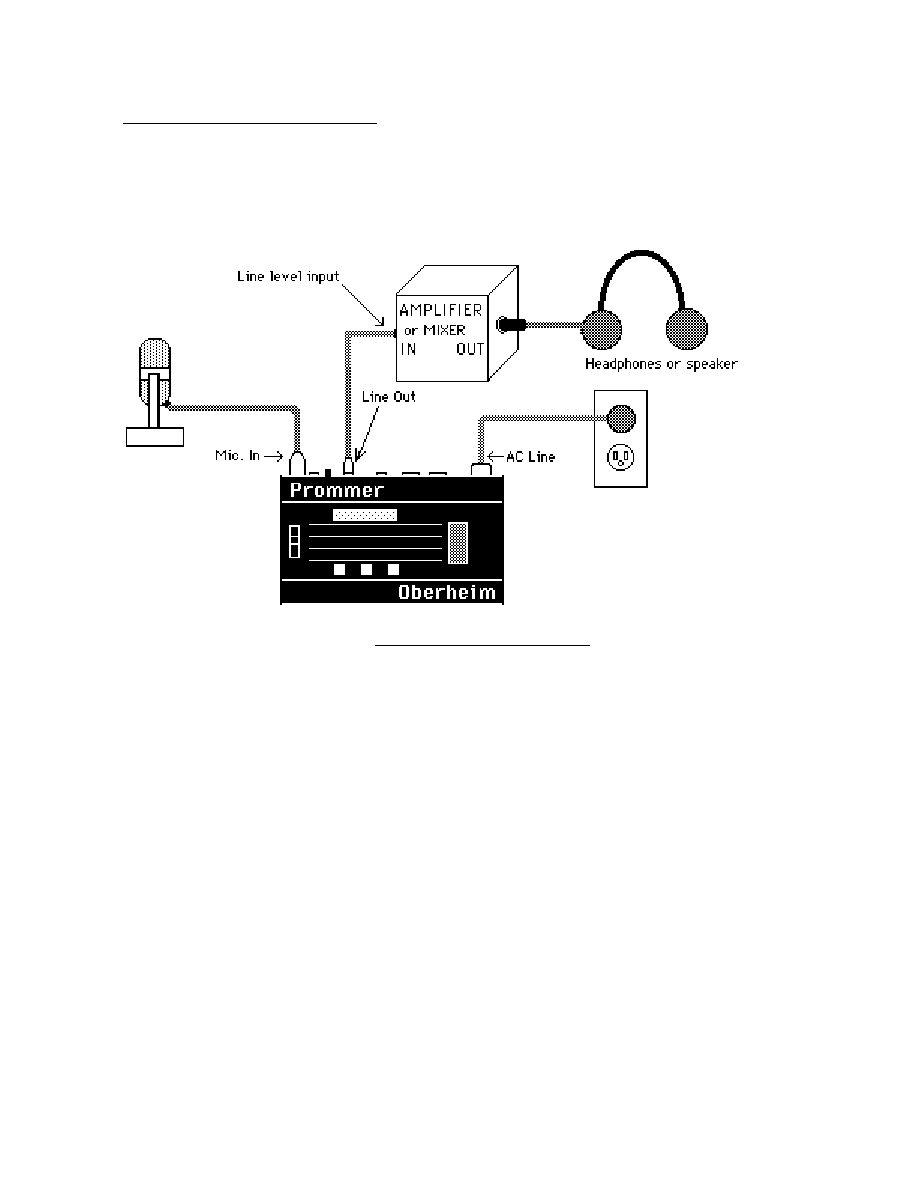
Figure 1 - Basic setup
ABOUT THE S W I T C H E S
The switches that control the Prommer are arranged in three main groups; the
function switches which are arranged in a rectangular pattern in the center of the
front panel, the number pad and data entry switches on the right side of the
panel, and the three raised pushbuttons on the lower part of the front panel -
PLAY, RECORD and EXECUTE.
Most of the function buttons have more than one function and in this manual
these switches will be referred to mainly by their topmost label. Function switches
are grouped by function type into horizontal rows. The top row of buttons deal
with MIDI control of the Prommer. The next row contains EPROM functions, the
row beneath that has Sound Modification functions, and the bottom row contains
sampling, playback and other miscellaneous controls.
Please notice the button just beneath the right side of the function buttons. This
is the PARAMETERS button and is also marked with a plus sign "+". Also notice
that some of the function buttons have labels preceded by a plus sign. This
indicates that this is a Parameter of the Function listed above it and to access the
Parameter, you must first press the desired function button, and then press the
PARAMETERS button.

Prommer User's Guide
Getting Started
10
MAKING YOUR OWN S O U N D S
The following is a step by step explanation of how to get the Prommer to record
and play back a sound and some exercises in using some of the simple functions.
CONNECTING THE PROMMER (See figure 1).
a) Connect the AC cable and plug it in to a suitable source of power. Turn the
Prommer power switch ON and set the input level control all the way down.
b) Connect an amplifier to the Prommer's line output. If you will be using a
microphone, the amplifier output should go to headphones or speakers
physically distant from the microphone in order to reduce the possibility of audio
feedback.
c) Connect a low impedance microphone to the MIC. INPUT of the Prommer using
a standard microphone cable and set the input level switch on the back panel to
+4.
RECORDING A S O U N D
1. Set the record level.
Speak into the microphone and say "Hello" a few times. Watch the LED meter on
the Prommer and raise the INPUT LEVEL control until the yellow LED lights while
you speak.
2. Get ready to record.
a) Press the "SELECT BLOCK" button.
b) Press "1" to select block number 1.
c) Press the "PARAMETERS" button to see the address of block 1.
d) Press "0" to set the address of block 1 to zero.
e) Press the PARAMETERS button again to see the length of block 1.
f) Press "3" and then press "2" to set the length of block 1 to 32k.
g) Press the "SAMPLE RATE" button.
h) Press "CLEAR" to set the sample rate to 32kHz.
i) Press the "SAMPLE RATE" button again to set the record threshold.
j) Press "CLEAR" to set the threshold to -18db.
3. Record a sound.
a) Be quiet.
b) Press and HOLD the "RECORD" button. Display will read
"PRESS PLAY. . .".
c) Press the "PLAY" button and then release both buttons. The display should
read: "RECORDING. . ."
d) Speak into the microphone - "Hello". The display will read
"RECORDING. . .NOW" for about one second.

Prommer User's Guide
Getting Started
11
PLAYING BACK A S O U N D
1. Play the sound normally.
a) Press the "PLAY" button and listen through the headphones. You should be
able to hear the sound you just recorded.
2. Try changing some playback parameters.
a) Press the "SAMPLE RATE" button until the sample rate is displayed. Press
the "<" button and see that the rate changes to 24kHz.
b) Press "PLAY" and hear how the sound has changed. Press the "<" button
again to change the sample rate to 16khz and 12kHz. Press "PLAY" at each
sample rate and listen to how the pitch changes.
c) Set the sample rate back to 32kHz.
d) Press the "TRANSPOSE" button. The display should read
"1 TRANSPOSE= +0".
e) Use the number pad to enter a number between 1 and 48. Press "PLAY". Use
the "+/-" button to change the sign of the transpose value displayed. Press
"PLAY" again. Try entering different values and listening to how the sound
changes each time.
f) Set the transpose back to zero.
MODIFY THE S O U N D
a) Press the "REVERSE" button. The display will read "1 REVERSE *".
b) Press the "EXECUTE" button. The display will read "BUSY. . ." for a moment.
c) Press "PLAY". Hear how the sound plays backwards. Press "EXECUTE"
again. Press "PLAY" and notice that the sound has returned to normal.

Prommer User's Guide
Getting Started
12
PLAYING SOUNDS FROM THE OBERHEIM STOCK E P R O M
An EPROM containing some sample sounds and a demonstration program
comes packaged with the Prommer. Before handling the EPROM, please skip
ahead and read the warnings at the beginning of Chapter 6 (EPROMs).
a) Insert the Oberheim EPROM in the socket on the front panel. Be sure to raise
the lever first, orient the EPROM with its notch toward the rear of the Prommer,
align all the pins correctly and press the lever down to secure it.
b)
Select
the
correct
EPROM
type
.
Press the button labelled PROM SELECT and use the right arrow button (>) to
step through the choices of EPROMs until the display reads:
PROM = 27256, 32K
c)
Load
setup
parameters
from
the
EPROM
.
Press the LOAD DATA button (three times) until the display reads:
LOAD SETUP *
d) Press EXECUTE to load a new set of block parameters from the chip.
e) Press the LOAD button again until the display reads:
x LOAD DATA * ( where x is any number)
f) Use the number pad to enter the number sixteen ( Press [1] and then
press [6] ). This selects block number sixteen.
g) Press EXECUTE. The EPROM data will be loaded into memory.
h)
Play
some
sounds
. Select blocks 1, 2, 3, or 4 and play the sounds. These
sounds are included to demonstrated some of the possible uses of the Prommer.
i)
Run
the
demo
program
. Select block 10. Press the button labelled "RUN
PROGRAM". Now,
press
and
hold
the PARAMETERS button and then press the
EXECUTE button. The program loaded from the Oberheim demonstration
EPROM which is now residing in block 10 is now running. You should see a
message scrolling across the display. Be sure you use the RUN PROGRAM
function ONLY when a block containing a valid PROGRAM is selected.
THIS IS JUST A S A M P L E
There are lots of other things you can do with the Prommer. Feel free to
experiment - and have fun! Read the rest of this guide for complete details on
how all the functions work and please read the warnings at the beginning of the
section on EPROMs before handling any EPROMs.

Prommer User's Guide
Blocks
13
Chapter
3
-
B L O C K S
A
block
is a continuous section of memory which may be located in any part of the
Prommer's available memory. There are sixteen blocks, each of which is user
definable. The currently selected block is the section of memory used for
recording, playback, and all other Prommer functions.
SELECTING A B L O C K
The SELECT BLOCK function is used to select the
current
block
. The sixteen
blocks are numbered 1 through 16. Press the SELECT BLOCK button and the
display will show the current block like this:
1--SELECT B L O C K
You may use the number pad or the arrows to change the current block number at
this time.
DEFINING A B L O C K
To define a block you must specify it's
address
and length
.
The Prommer contains 65,536 bytes of sound storage memory numbered 0
through 65535. For convenience, we usually describe addresses and length in
1K units (one K is equal to 1024), so we say the Prommer has a maximum memory
capacity of
64K
(64 x 1024 = 65536). The reason for using a strange number like
1024 is that the capacities of computer memory chips (like EPROMs) are multiples
of 1024, a result of the binary numbering system used by most computers. So, to
make a sound fit
exactly
on an EPROM, its block length needs to be an exact
multiple of 1024 and 2, 4, 8, etc.
BLOCK A D D R E S S
The
address
of a block is a number describing where the block starts in memory.
To define the address of a block, press the PARAMETERS button (from the
SELECT BLOCK display). The display should now show something like :
1 ADDRESS = 1 6 K
The number on the left of the display is the current block number and the number
on the right is the currently selected starting address for the block shown in
multiples of 1024 (indicated by the letter "K"). The range of addresses is from 0
to 63k or 0 to 65535.
By using the number pad or the arrows, you can change the block address.
Note that the address changes in increments of 1k. If you want to define the
address with high resolution, press the [#] button:
1 ADDRESS = 1 6 3 8 4
The display will now show the address in whole number form and you can use the
number pad or arrows to change it. Press the [#] button again and you will go
back to viewing the address in 1k form. Notice that if you have entered an
address that is not an exact multiple of 1024, a dot will show on the display
between the number and the "K" symbol to remind you.

Prommer User's Guide
Blocks
14
BLOCK L E N G T H
The length
of a block is the number of bytes (samples) in that block. To define
the length of the current block, press the PARAMETERS button again and the
display will show you the length.
1 LENGTH = 8 K
You can change the block length by using the number pad or the arrows. As with
the block address, you can also define the length in high resolution mode, by
pressing the [#] button:
1 LENGTH = 8 1 9 2
Pressing the [#] button again will take you back to the 1k increment length
display.
Block lengths are limited by the end of the Prommer's memory. For example, a
block at address 62k would have a maximum length of 2k. There is also a
minimum block length of 16 bytes for recording and playing back sounds. For any
other purpose, the minimum block length is 1.
If you wish to have two blocks be consecutive in memory, just add the length of
the first block to its address to get the address of the second block. Example: to
have two consecutive 8k blocks, where block #1 starts at address 16k, block #2
should start at address 24k.
See figure 2 on the next page for more information about blocks.
BLOCK PROTECT
Press the PARAMETERS button one more time (from the Block Length display)
and the display will show the
protect status of the current block:
1 U N P R O T E C T E D
By pressing the +/- button, you can toggle the protect status between
PROTECTED and UNPROTECTED.
(The number pad and arrows can be used at this point to change the current
block number, which is displayed at the left. This enables you to quickly check
the status of all blocks.)
When a block is protected, the data in it normally cannot be changed or recorded
over.
However , if one block overlaps another, changing the data in one will
overwrite the data in the other whether it is protected or not. For this reason it is
important to understand the concept and be aware of all overlapping blocks.

Prommer User's Guide
Blocks
15
figure 2 - PICTURE: Block examples goes here. . .

Prommer User's Guide
Blocks
16

Prommer User's Guide
Sampling
17
Chapter
4
-
SAMPLING
SAMPLE R A T E
The SAMPLE RATE function sets the basic sampling rate for recording and
playing a sound. Ther Prommer has four possible recording sample rates -
32kHz, 24kHz, 16kHz, and 12kHz. Each block is assigned its own sample rate.
To set the sample rate for the current block, press the SAMPLE RATE button:
1 RATE = 3 2 K H Z
The number on the left is the current block and the sample rate is shown on the
right. The sample rate may now be changed by using the arrow buttons.
The sample rate determines two things about a sample - the audio bandwidth and
the speed at which memory is filled during recording. A high sample rate will give
you a higher quality recording than a low sample rate, but it will also use up
memory faster. For example, you can record about five and a half seconds in 64k
of memory at the lowest sample rate of 12kHz, but increasing the sample rate to
32kHz gives you only about two seconds of record time for the same amount of
memory.
Sample
rate
/
Block length
bandwidth
4k
8k
16k
32k
64k
12kHz / 4.8kHz
0.34
0.68
1.36
2.73
5.46
16kHz / 6.4kHz
0.25
0.51
1.02
2.04
4.09
24kHz / 9.6kHz
0.17
0.34
0.68
1.36
2.73
32kHz / 12.8kHz
0.13
0.25
0.51
1.02
2.04
Table 1 - Recording time (in seconds)
The sample rate may be important when you record sounds for drum chips - when
choosing a sample rate, consider the fact that most Oberheim DMX and DX drum
voices are designed for sounds originally sampled at 20kHz to 40kHz. For
example, a sound recorded at 12kHz will not play back on a DMX Snare drum
voice at the proper rate (due to limited tuning range). Refer to appendix 1 for
approximate sample rates for various Oberheim drum voices.
RECORDING TIME DISPLAY
If you want to see just how much time is available for recording at the current block
size and selected sample rate, press the PARAMETERS button (from the Sample
Rate display):
16 TIME = 2047 M S
This is the recording time displayed in milliseconds. A millisecond is one
thousandth of a second (2047 milliseconds = 2.047 seconds). To return to the
Sample Rate display, press PARAMETERS again.

Prommer User's Guide
Sampling
18
RECORD TRIGGER T H R E S H O L D
The
record
trigger
threshold
is the input amplitude level that is required to start
the process of recording a sound. To set the record trigger threshold level, press
the SAMPLE RATE button again.
The display will show:
RECORD AT -18 D B
Use the number pad or the arrows to set the threshold level to any value between
0 and -45db. The number displayed corresponds approximately with the level
you see on the LED meter.
When the Prommer is in a "ready to record" condition, the recording will start
when the input signal level exceeds the record trigger threshold. The Prommer
uses a pre-record buffer so that the leading edge of the audio cycle that triggers it
will not be lost. This allows recording data starting with the first zero level crossing
before
the trigger point to eliminate any clicks or thumps that may be caused by
starting a sound at the wrong phase of a cycle.
If you want to be able to record immediately without waiting for the input signal to
trigger, just set the threshold level to its minimum value of -45. Recording will
then start as soon as record mode is entered (see below).
Pressing the SAMPLE RATE button again will take you back to the SAMPLE
RATE display.
RECORDING A S O U N D
To
record
a sound, press and hold the RECORD button. If the current block
length is greater than 15 bytes and the block is not protected, the display will
read:
PRESS PLAY. . .
Still holding the RECORD button, now press the PLAY button. The display will
now read:
RECORDING. . .
Now the Prommer will wait for the input signal to reach the record trigger
threshold. (You may now release both buttons.)
When the input signal becomes loud enough to cross the threshold, the
Prommer will start recording into the current block and the display will read:
RECORDING. . . N O W
Recording will continue until the current block is full.
After you record a sound you can play it back by pressing PLAY. You can re-
record a sound if you want to - just press RECORD and PLAY again.

Prommer User's Guide
Sampling
19
Note: Once the Prommer is in record-ready mode (when the display reads -
"RECORDING. . .") there is no way to leave this mode without recording a sound
unless you turn the power off and then on again. For example, if you forget to
plug in a microphone and you press RECORD and PLAY, the Prommer will ignore
all buttons on the front panel including STOP until a sound has been recorded.
Also, if you accidentally start to record over an unprotected block you wanted to
save, the first part of the block may be erased, even if you do turn the power off
before recording starts. This is because the current block is used as a pre-record
buffer and the first part of it will contain new samples even though the input signal
was less than the record threshold (possibly only a few bytes may be lost).
SETTING THE RECORD LEVEL TO MINIMIZE DISTORTION
Due to the nature of digital recording, you will get the best signal to noise ratio at
the highest recording level possible but when the level is increased beyond a
certain point, the signal will be clipped (distorted) suddenly. This is different from
recording on magnetic audio tape where you have a certain amount of
"headroom" and overload distortion happens gradually. For this reason, it is
important to monitor the record level carefully before and during the recording
process.
A good recording level should be around 0db on the LED peak meter. Anything
higher than about +3db will begin to overload the analog-to-digital converter and
the signal will distort. Sometimes this distortion may be just the thing to give a
drum sound some extra "punch", but usually it is undesirable.
Before recording, check the level by producing the sound you are going to
record a few times and watching the meter. Adjust the input level control until the
meter reads about 0db or +3db at the loudest point. If the level is too high, the
sound will be distorted by clipping, and if too low, the background noise may
become more noticeable.
Although setting the record level with the meter is a good starting point, the most
reliable way to detect overload distortion is by listening
to the output of the
Prommer with I
dle
Bypass
mode OFF. The sound you will then hear is the same
as that which will be recorded, that is, the signal that has been converted from
analog to digital and then back to analog again.
If the sound coming out of the Prommer is distorted even at low levels, the
problem may be that the output level of the Prommer is too high for your amplifier.
Be sure that the Prommer is connected to a
Line
Level input (+4 dBm).
Another possible cause of distortion is in the input section. If the level of the
device connected to the input of the Prommer is too high, the input amplifiers
may be overloaded. Also, be sure the input sensitivity switch on the rear panel is
set for the proper range of input levels (+4 or -10) and if necessary, reduce the
level of the input device.

Prommer User's Guide
Sampling
20

Prommer User's Guide
Playback Modes
21
Chapter
5
-
PLAYBACK
M O D E S
The Prommer is able to play back sounds that have been recorded into it
monophonically (one block at a time). The audio output should be connected to
an amplifier with a volume control or to a line level input of an audio mixing board.
You can play back sounds in three different ways; with the PLAY button on the
front panel, with an external trigger or with a MIDI keyboard or other MIDI
controller.
There are four basic modes for playing back sounds -
normal ,
gated
, loop
, and
gated
/ loop
. The play mode may be set differently for each individual block. To
show the play mode for the current block, press the PLAY MODE button:
1 MODE = N O R M A L
You can use the arrows to select the mode now. The number on the left of the
display is the current block.
NORMAL M O D E
In
normal mode, when you trigger a sound, the current block will play through to
its end unless it is retriggered, or the STOP button is pressed.
GATED M O D E
In
gated
mode, the sound will only play as long as the PLAY button or MIDI key is
depressed. Releasing the key will stop the playback immediately.
LOOP M O D E
Loop
mode will play a sound repeatedly after it is triggered and will only stop when
the STOP button or another key is pressed.
GATED / LOOP M O D E
Gated
/ loop
mode is similar to loop mode except that the looping happens only
as long as the PLAY button or MIDI key is depressed. When the key is released,
the loop will finish playing, and then the remaining part of the sound will play.
LOOP P O I N T S
You may set the loop points for a block so that looping occurs only in a selected
section of the sound.
The section that will repeat is defined by the loop
start
point and the loop
end
point . To access the loop start point, press PARAMETERS (from the Playback
Mode display):
1 LOOP ST.= 0
The CLEAR button will set the loop start point to the start of the block.
Press the PARAMETERS button again to set the loop end point:
1 LP. END = 8 1 9 1
The CLEAR button will set the loop end point to the end of the current block. As
always, the number on the left of the display is the current block. You can use the
number pad to change the start and end points, or you may use the arrows.
Loop points are specified as an offset from the beginning of the current block.
So, no matter where the current block is located in memory, a loop start point of
zero always indicates the beginning of the sound.
Prommer User's Guide
Playback Modes
22
AUTOMATIC ZERO-CROSSING D E T E C T I O N
You may notice that
when
you
use
the
arrows
to
change loop
points
, the
numbers will move in apparently random size steps. What happens is that the
data in memory is scanned until the loop address reaches
the
next
audio
zero
crossing
, that is the point where the audio signal in memory changes from
positive to negative or from negative to positive. This is done to make it easier to
set smooth sounding loop points.
Note: If the current block is empty, and there are no zero crossings, when you
use the arrows the loop point will jump to the maximum or the minimum address
offset for the block.
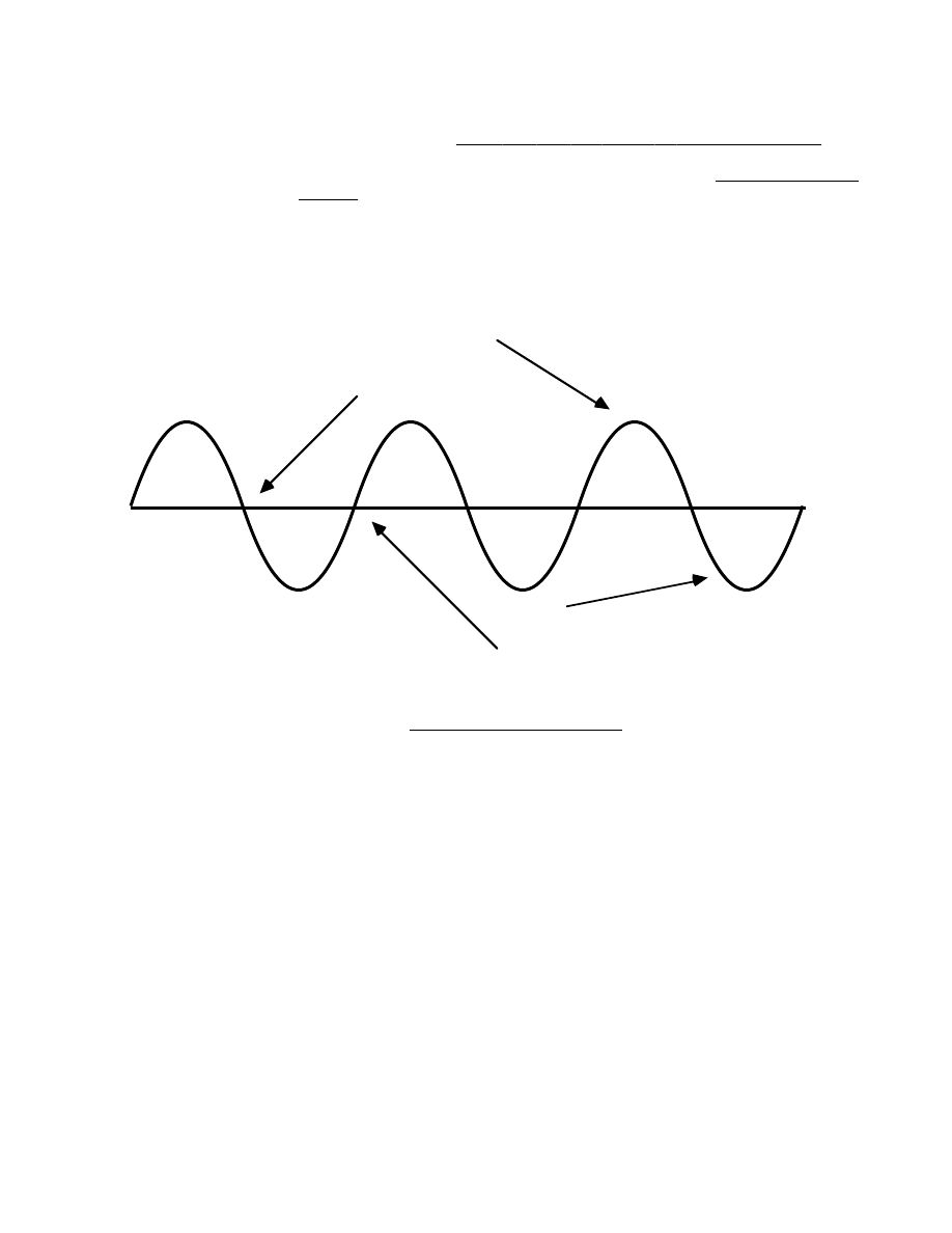
Zero crossing
Zero crossing
Positive part of signal
Negative part of signal
0
+
-
Figure 3 - Zero Crossings
GUIDELINES FOR SETTING LOOP P O I N T S
It will probably take some practice and patience (and a good sample) in order to
get a good sounding loop. With some sounds it is just not possible to find any
good loop points. For example, a sound that continually increases or decreases
in pitch or volume will not loop smoothly. As the playback switches from the end
point of the loop back to the beginning you will hear a sudden change in the pitch
or loudness. However, a sound with even a small amount of sustained timbre can
be looped successfully if you find the right location for the loop points.
If you want a sound that will stop quickly after releasing the PLAY button, set both
the loop start and end points near the end of the block. If you want a sound to
have a long release, set the loop points near the beginning or middle of the
block.
Setting the loop points is usually just a matter of trial and error. Use the number
pad to set the loop points to approximately where you want them, and then use
the arrows to move each loop point to its nearest zero crossing. Now listen to the
sound and alternately try changing the loop start point and then the loop end
point until the loop sounds OK. Notice that if you move a loop point one step
(zero crossing) at a time, every other step will make a bad sounding loop. This is
because at these points, the phase of the signal changes abruptly when the
sound loops back.

Prommer User's Guide
Playback Modes
23
PLAYBACK TRANSPOSITION
The apparent pitch of sounds may be changed by transposing the sample rate for
playback. Press the TRANSPOSE button to view the current transpose value:
1 TRANSPOSE = + 0
Use the number pad or the arrows to set the transpose amount for the current
block in musical semitones. (Example: +12 = transpose up one octave, -5 =
transpose down five semitones, etc.). The transposition is based on the currently
selected sample rate, so playing a sound at a sample rate of 32kHz, transposed
down by -12 will give the same result as playing the sound at a sample rate of
16kHz with zero transposition.
The range of transposition from the front panel is plus or minus 48, which is a
range of eight octaves. There is more range available if you use a MIDI controller
to play the sound. MIDI note number 60 (Middle C) corresponds to the normal
playback rate for the current block including the set transposition. Higher or lower
MIDI notes will play the sound at a chromatically higher or lower pitch respectively.
Note: The Prommer can't actually play data at sample rates faster than 32kHz but
appears to do so by sampling at a lower rate and playing only every other byte of
the sound (or every fourth byte or eighth byte, etc.). This may cause an unusual
change in the timbre of some sounds - especially sounds with large amounts of
high frequency (such as cymbals).
FINE TUNING PLAYBACK
You can also make fine tuning adjustments in the playback of a sound. Press the
TRANSPOSE button again:
FINE TUNE = + 0
There is a fine tune value associated with each block, but the current block
number is not shown in the Fine Tune display. The range of fine tune values is
from -127 to +127. This range covers approximately two semitones, so a fine
tune value of +127 is equivalent to one semitone of up-transposition. Use the
number pad or the arrows to set the fine tune.
OUTPUT FILTER C O N T R O L
The Prommer has a voltage controlled low pass filter in its playback output stage,
and the frequency of the filter normally tracks the playback rate to reduce
sampling noise, but for special effects, you can set the filter frequency to a fixed
point.
Press the TRANSPOSE button again:
1 FILTER = T R A C K
By using the arrows or the number pad, you can enter a value between 1 and 255
for the filter frequency for the current block, with 255 being "wide open" and 1
being the lowest filter cutoff frequency. These numbers are not calibrated to the
actual cutoff frequency and should just be used for reference.
1 FILTER = 1 2 3
You can set the filter back to tracking mode by entering a value of zero or by
pressing the CLEAR button. The filter is also controllable by MIDI pressure and/or
velocity. MIDI control will override the filter setting shown here. See the section
about MIDI for more information.
EXTERNAL TRIGGERING

Prommer User's Guide
Playback Modes
24
As mentioned earlier, the playback of sounds may be triggered with an
external
trigger through the quarter-inch phone jack on the back panel. This trigger may
be a logic signal such as the "click" output of a drum machine, a high level
percussive audio signal, a drum pad output, or a momentary footswitch. To
enable the external trigger, press the EXT. TRIGGER button:
EXT. TRIGGER O F F
Use the +/- button or the arrows to enable the trigger. Use the CLEAR button to
disable the trigger. The trigger polarity may be set to positive or negative ( O N +
or ON- ). If an audio trigger is used you will probably need to set the retrigger
delay. Press the PARAMETERS button now:
RETRIG. DLY.= 0
Use the number pad or arrows to set the retrigger delay. The arrows will
increment or decrement the delay value by 128. The retrigger delay is the
number
of
bytes
that will play after a sound is triggered before a new external
trigger will be recognized. For example, at a playback rate of 32kHz, a retrigger
delay of 3200 will correspond to an actual delay of 1/10 second. If a very
percussive audio signal or a click is used for the trigger, the delay may be set fairly
short and you can retrigger a sound quickly. If a more complex waveform is used,
its level may have to be decreased or a longer delay set to avoid multiple false
triggers.
Note: The external trigger will not work in GATED playback mode.
PRE-EMPHASIS / D E - E M P H A S I S
Each block may be recorded with or without EMPHASIS. This is an equalization
circuit in the Prommer that boosts midrange and high frequencies during
recording (pre-emphasis), and cuts midrange and high frequencies upon
playback (de-emphasis) Press the EXT. TRIGGER button again to see the
EMPHASIS display:
1 EMPHASIS O F F
You can toggle the emphasis mode with the +/- button. Emphasis ON acts as a
sort of noise reduction when used on both input and output. When recording
sounds for drum machines, remember that a sound recorded with pre-emphasis
will not neccessarily sound natural on a drum voice without de-emphasis, but you
can add brightness to a sound by recording it with emphasis ON and playing it
back with emphasis OFF.
IDLE BYPASS M O D E
There is a function called IDLE BYPASS which bypasses the analog-to-digital
converter circuitry in the Prommer whenever a sound is not being played or
recorded. This will eliminate the sampling noise you will normally hear when
monitoring the input with no signal coming in. If you are recording sounds, you
should set the idle bypass mode OFF. This will enable you to hear any clipping
distortion as it happens and make the neccessary adjustments in the input level.
To turn the IDLE BYPASS on or off, press the EXT.TRIGGER button one more
time:
IDLE BYPASS O F F
Use the +/- button or the arrows to toggle the idle bypass mode.
Prommer User's Guide
EPROMs
25
Chapter
6
-
E P R O M s
The Prommer is able to program or "burn" several different types of PROMs
(Programmable Read Only Memories), EPROMs (Eraseable PROMs) and
EEPROMs
(Electrically Eraseable PROMs). See appendix 2 for a full listing of
compatible types.
An EPROM is an integrated circuit chip that can be used for permanent or semi-
permanent data storage. The terms PROM and EPROM will be used
interchangeably throughout this manual - the only difference between them are
the part numbers and the fact that PROMs cannot be erased, while EPROMs may
be erased by exposure to ultraviolet light and then re-programmed. EEPROMs
are a special type of PROM that can be re-programmed without having to be
erased.
You can use EPROMs to permanently store the sounds you have sampled with
the Prommer. Once you have a sound on an EPROM it may be reloaded into the
Prommer at any time or used in a drum machine such as the Oberheim DMX.
All EPROM functions operate only on the currently selected block of memory.
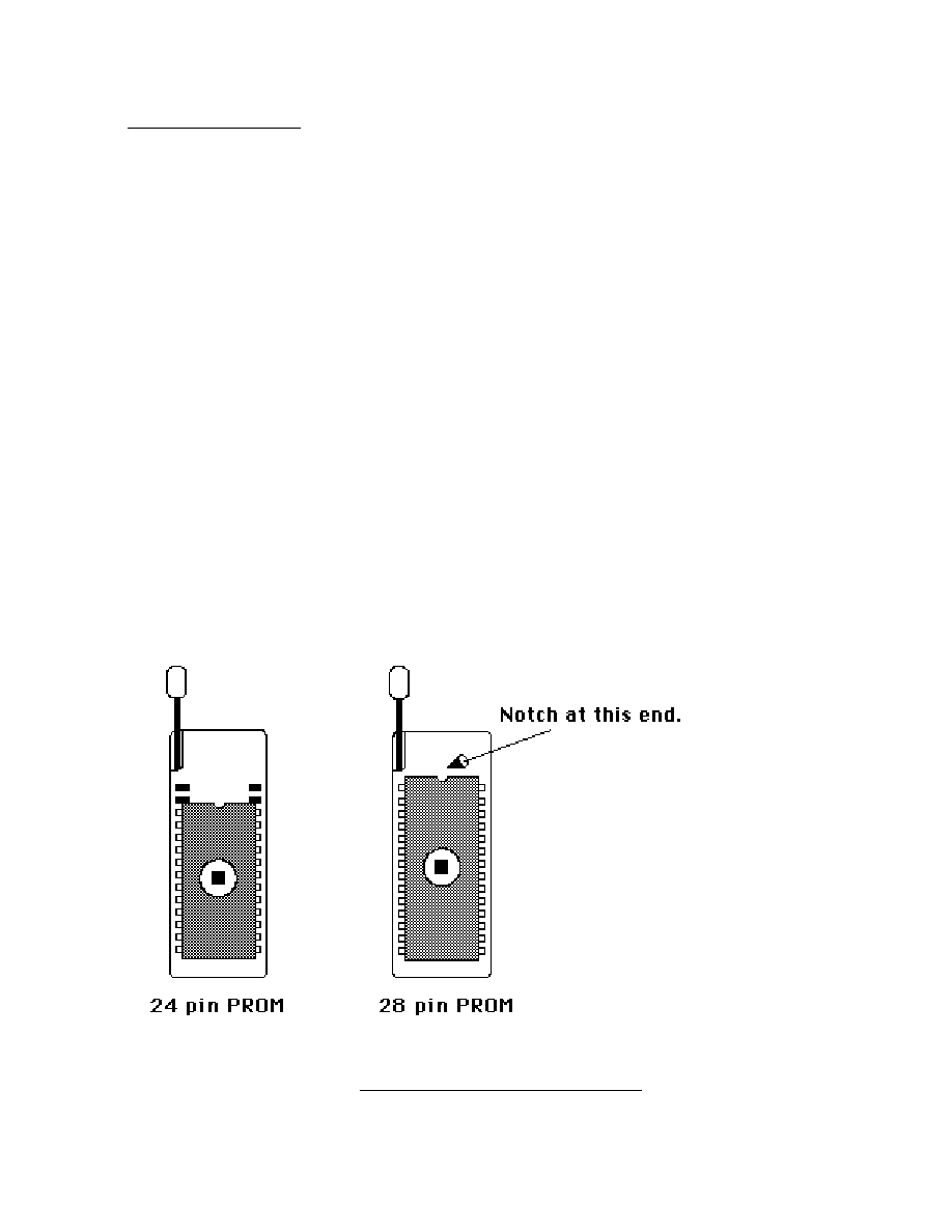
All EPROM operations require a chip installed in the socket on the front panel
according to the diagram in Figure 4 - to install an EPROM, first lift the socket
handle, insert the EPROM (make sure all the pins are straight) and then push the
handle down to secure it. Notice that 24 pin EPROMs must be placed only in the
lower holes of the socket.
Note: DO NOT remove or insert an EPROM while any EPROM operation is in
progress!
Figure
4
-
PROM
Orientation

Prommer User's Guide
EPROMs
26
CAUTIONS
!
1. EPROMs are very sensitive to damage and you should always use great care
and caution in handling them. A major cause of permanent EPROM failure is
static
electricity
damage. You should
always
keep your EPROMs in static
protective foam or tubes when they are not in use. Do not touch an EPROM after
walking across a carpet on a dry day without grounding yourself first to dissipate
any electrical charge.
2. Try not to bend the leads on an EPROM as they are delicate and will break
easily.
3. EPROMs must always be oriented properly in their sockets with the notch in
the end facing the correct way.
VERY
IMPORTANT
NOTE
!
Each type of EPROM requires a different programming
algorithm
and some types
use different pins for different functions. The Prommer must be configured
differently for each type so you must
always
specify what type of EPROM you are
using.
SELECTING THE EPROM T Y P E
To specify an EPROM, press the PROM SELECT button and the display will
show the currently selected PROM type:
PROM= 2764, 8 K
Use the arrows to select the type you will be using.
The display example shown here indicates the part number of the EPROM (2764)
and the size of the EPROM in bytes (8K). The EPROM size is not printed on the
EPROM itself - it is just shown here for reference in comparing block sizes to
EPROM sizes.
Please read the part number of your EPROM carefully and be aware that there
may be differences even in similar part numbers - for example, a 2732 is not the
same as a 2732A and a Toshiba TMM27256D is not the same as an Intel 27256.
Permanent
damage
may
occur if you try to program an EPROM when the wrong
type is selected.
Some EPROM part numbers are followed by a dash and a number (Example:
MBM2764-30). The number following the dash (30) indicates the access time of
the EPROM and can be ignored for most drum machine type applications. Note
that some chips may also be marked with a date code such as 8523 - indicating
that the chip was manufactured in 1985 during the 23rd week of the year. Don't
let this confuse you. The actual part number is usually fairly obvious.

Prommer User's Guide
EPROMs
27
EPROM ADDRESS O F F S E T
Normal program and read operations start at the first address location of the
EPROM and count upward, but you can set a
PROM
offset address if, for
example, you want to program only the second half of an EPROM. While the
display is showing the PROM type, press the PARAMETERS button to display
the PROM offset:
PROM OFFSET= 4 K
Use the number pad or the arrows to set the offset in 1k increments.
Be
sure
to
reset
the
offset
to
zero
for
normal
operation
. Note: the PROM offset is always
reset to zero when the AC power is turned off.
BLANK EPROM VERIFICATION
You can test an EPROM to verify the fact that is blank. Press the CHECK
ERASURE button:
CHECK ERASURE *
This function will test the EPROM in the socket on the front panel to see if all bits
are equal to 1 (ready to be programmed). Press the EXECUTE button to check
erasure. If the EPROM is blank, the display will read OK after a moment. If the
EPROM is not blank, the display will show the address of the first non-blank
location:
ERROR AT 1 0 0 9
ERASING E P R O M S
EPROMs may be erased by exposing them to a source of ultraviolet light. If you
use EPROMs with your Prommer, you will most likely need an EPROM eraser.
Most EPROMs can be erased with 5 to 30 minutes of exposure in an EPROM
eraser. Be sure to follow the manufacturer's instructions when using an eraser
and DO NOT expose your eyes to ultraviolet light.
It is also possible to erase an EPROM by exposing it to sunlight, since the sun
produces ultraviolet light. It may be necessary to leave an EPROM out in the sun
for a day or more, depending on the weather, to completely erase it.
Remember to put an opaque label over the window of any EPROM that you plan
to save to avoid
accidental erasure.
WHAT IS BLANK ?
As far as digital audio is concerned, a blank EPROM is not the same as a silent
one. When a PROM or EPROM is new or erased, each byte of memory is set to all
ones (11111111). If you were to play a blank EPROM in a drum machine you
would hear a loud thump. If for some reason, you want to program a part of an
EPROM with a section of silence, you should program that part with
zeros
, -- don't
just leave it blank.

Prommer User's Guide
EPROMs
28
COMPARING EPROMS WITH M E M O R Y
Data on an EPROM may be compared with the data in the current block. Press
the CHECK ERASURE button again:
1 COMPARE DATA *
Press EXECUTE to compare. If the data in the current block doesn't match the
data in the EPROM exactly, an error message will be displayed.
PROGRAMMING E P R O M S
To program an EPROM, press the PROGRAM PROM button and the display will
read:
1 PROGRAM P R O M *
The number at the left shows the current block number which is the block that will
be programmed onto the EPROM when you press EXECUTE. The current block
may be changed at this point by using the number pad or the arrows.
After having selected the correct EPROM type, and the correct block, be sure
that your EPROM is secured correctly in the socket on the front panel and then
press the EXECUTE button.
The EPROM is checked for erasure at this time and if it is blank, programming will
begin and the display will read:
PROGRAMMING. 3 1
The number in the display is a count-down number provided to indicate the time
remaining before the programming process is complete. The number will start at
different values depending on what size EPROM you are using.
To avoid accidental destruction of data on a previously programmed EPROM, if
the EPROM is
not blank at the time programming starts, the display will read:
ARE YOU SURE. . .
If you wish to continue, press EXECUTE a second time. If not, press the STOP
button to cancel the program command.
After all the data has been programmed, it will be verified one more time, and if all
the data has been programmed correctly, the display will read OK.
You can press the STOP button at any time to interrupt the programming
process, but if you want to restart, you must do so from the beginning.
BLOCK / EPROM LIMITS
If the current block is not equal in size to the EPROM being used, the
programming process will stop as soon as either one reaches its limit. For
example - if you program a 4k block onto an 8k EPROM, the programming
process will stop after the first 4k bytes have been programmed, leaving the
second half of the EPROM blank or unchanged. Or if you program a 16k block
onto an 8k EPROM, only the first half of the block will be programmed.

Prommer User's Guide
EPROMs
29
IN CASE OF A PROGRAMMING ERROR . . .
If an error occurs during the programming process, an error message will show on
the display. You should double check the EPROM type that is selected against
the part number printed on the EPROM. If the EPROM type is correct, you can try
programming the EPROM a second time, in case the error was transient. If the
error happens again, as a last resort, try erasing the EPROM and program it again.
Assuming there is no problem when programming other EPROMs of the same
type, if the error still happens, the EPROM is defective and should be discarded.
If the same error happens when using other EPROMs, the Prommer may have a
hardware problem. If you suspect a hardware problem, contact your nearest
Oberheim Authorized Service Center and do not attempt to program any more
EPROMs.
If you have a problem re-programming an EEPROM (Electrically Eraseable
PROM), you may need to erase it before re-programming. To erase an EEPROM,
first select an unused block of memory the same size as the EEPROM (8k for a
9864 or 2864). Then, using the Prommer's bit function, set up the following
pattern: 11111111. Press EXECUTE and all the data in the block will be set to
ones (the same as an erased EPROM). Now, use the PROGRAM PROM function
to program the EEPROM with this new block. If the programming operation is
successful, the chip should now be blank. Now, try programming the desired
block onto the EEPROM.
LABEL YOUR E P R O M S !
To avoid almost certain confusion, you should always put a label on an EPROM
immediately after it has been programmed and give it a descriptive name such as
"SNARE 31", "STANDUP BASS MID. C", etc. If the sound on the EPROM is
used in the Prommer with looping or emphasis it would be good to write that data
on the label also. If there is not room to write all the necessary information on the
label, you might consider keeping a logbook of all your EPROMs and keep track
of them by name or by an index number and write all the information in the book.
COMPANDED DATA VS. LINEAR D A T A
Sounds are recorded and played in the Prommer in a digital format called eight-bit
companded
. Oberheim and many other drum machines also use this format. The
other eight bit format used in the industry is known as linear . Linear format is the
simplest and most inexpensive to use but has a lower dynamic range than
companded. Companded format is better suited for reproducing audio signals.
The Prommer has the ability to convert data from one format to the other.
PROGRAMMING LINEAR E P R O M S
If you want to program an EPROM for use in a linear drum machine, you can use
the
program linear function. Press the PROGRAM PROM button again and you
will see the display:
1 PROG. LINEAR *
This function works the same as PROGRAM PROM except that just before
programming each byte, the data is converted from companded to linear format.
The data in the Prommer's memory is not changed by the process, only the data
on the EPROM is converted.

Prommer User's Guide
EPROMs
30
Note: If you use the COMPARE DATA function on a chip that has been
programmed as linear, the data will not compare correctly, since the data on the
chip was converted to linear but the data in memory is still companded. However,
immediately after programming, the data is automatically compared in the proper
format, so you can be assured that if the display reads OK after linear
programming, the chip has actually been programmed correctly.
SAVING A PROMMER S E T U P
If you have spent some time setting your Prommer to play several different
sounds from a keyboard with blocks assigned to different zones, and various
transposes for each block, for example, you may want to save these set-up
parameters for later use. You can do this by using the Program Setup Data
function. Press the PROGRAM PROM button again:
PROGRAM SETUP *
If you press EXECUTE now, all block and global parameters currently set in the
Prommer will be programmed onto the EPROM in the socket.
The Program Parameters function does
not check erasure before programming,
so use it with care.
All parameters are saved including block addresses and lengths, loop points, MIDI
zone limits, MIDI channel, and all other mode and status information. A special
code is saved at the beginning of the data to identify it as Prommer Setup Data.
All the data fits in less than 1k bytes, so you can save several Prommer set-ups on
one EPROM by using the PROM offset function. You can save up to eight sets
of parameters in an 8k EPROM or 32 sets in a 32k EPROM.
You may also save setup and sound data on one chip; for example, you can
program the Prommer setup data onto a 27256 EPROM at a zero PROM offset,
and then program a 31K block containing one or more sounds onto the same
EPROM by setting the PROM offset to 1k. (This is how the Oberheim Prommer
Factory Stock sound chip was made.)
LOADING DATA FROM E P R O M S
Data that is already on an EPROM may be loaded into the current block. Press
the LOAD DATA button again to get the display:
1 LOAD DATA *
You can change the current block number (displayed at the left) with the number
pad or the arrows at this point. When you press EXECUTE, the data in the
EPROM in the socket will be copied into the current block (if the block is not
protected). If the block size is smaller than the EPROM, only the first part of the
EPROM data will be loaded. If the block size is larger than the EPROM, the
EPROM data will be loaded into the beginning of the block leaving the remaining
portion undisturbed.

Prommer User's Guide
EPROMs
31
LOADING LINEAR E P R O M S
You can also load linear format data from EPROMs into the Prommer. Press the
LOAD DATA button again:
1 LOAD LINEAR *
This is the same as the load
data
function except that the data is converted from
linear format to companded before storing it in the current block.
LOADING SETUP DATA FROM E P R O M S
To retrieve set-up parameters from an EPROM that were saved using the
Program Setup function, press the LOAD DATA button again:
LOAD SETUP *
When you press EXECUTE, if the data on the EPROM in the socket has the
correct identification code at its beginning, the parameters will be loaded into
memory. Note that this function doesn't affect the sound data at all, just the
settings such as block addresses, zone limits, etc.
FOR SERIOUS PROGRAMMERS O N L Y
An advanced feature of the Prommer is the ability to load a program written in
6809 machine language into memory and run it. For more information please
refer to the Prommer Service Manual. When you press the RUN PROGRAM
button the
run
program
display will appear:
1 RUN P R O G R A M *
If you have loaded a valid 6809 program into the current block, you can start
execution of the program from the first address of the current block, by pressing
and holding the PARAMETERS button and then pressing EXECUTE. If the data
in the current block is not specifically a 6809 program DO NOT TRY TO RUN IT !
Unpredictable results will occur including possible loss of data in memory and
probable "lock-up" of the machine.
INTERNAL EXPANSION E P R O M
There is additional memory space available inside
the Prommer for possible future
program enhancements. If your Prommer was shipped from the factory with an
EPROM installed in this socket, you can access the programs it contains by
pressing the RUN PROGRAM button and then pressing EXECUTE. If no
EPROM is installed here, pressing EXECUTE will have no effect.

Prommer User's Guide
EPROMs
32
EXAMPLES
-
Programming
EPROMs
with
Blocks
of
different
sizes
A
reminder
about
block
and
EPROM
sizes
To see the length of the current block, press the SELECT BLOCK button and
then press PARAMETERS until the Length display appears.
To find the size of an EPROM, press the PROM SELECT button and look at the
EPROM size displayed at the far right. If the PROM size is not displayed, refer to
the EPROM cross reference in appendix 2, or use the part number of the chip as
a reference. PROM manufacturers often refer to the size of PROMs in the device
part number - with the last digits indicating the number of kilo
bit s of storage (a
kilobit is 1024 bits). To find the number of kilo
byte
s available, divide this number
by eight. For example a 27
256
contains 32k of data (256k divided by 8 = 32k).
So, we can say that the size of a 27256 EPROM is 32k.
All references to block length and PROM size in this manual and in Prommer
displays are in
bytes
.
EXAMPLE 1 - EPROM SIZE = BLOCK L E N G T H
The simplest way to program a sound onto an EPROM is to start out with a sound
in a block that is the same size (length) as the selected EPROM type. For
example, if you have a 2764 (8k) EPROM, and an 8k block, simply program the
EPROM directly from the block that contains your sound.
EXAMPLE 2 - MULTI-EPROM S O U N D S
Suppose you have a sound that uses 32k of memory in the Prommer and you
want to put it in a DMX Cymbal 3 voice card which requires four 8k (2764)
EPROMs for a total of 32k. To program your 32k sound onto four 2764s, you
need to set up four other blocks that cover the same portion of memory
containing your sound.
Let's say the sound in block #1 is a 32k block starting at address 0. You can
define four other blocks, each with a length of 8k:
Block #2 - Address 0, Length 8k
Block #3 - Address 8k, Length 8k
Block #4 - Address 16k, Length 8k
Block #5 - Address 24k, Length 8k
Now all you need to do is program your four EPROMs from blocks #2, #3, #4, and
#5 (see figure 5 on the next page).
(Remember to label your EPROMs immediately after programming so they don't
get mixed up.)
Prommer User's Guide
EPROMs
33
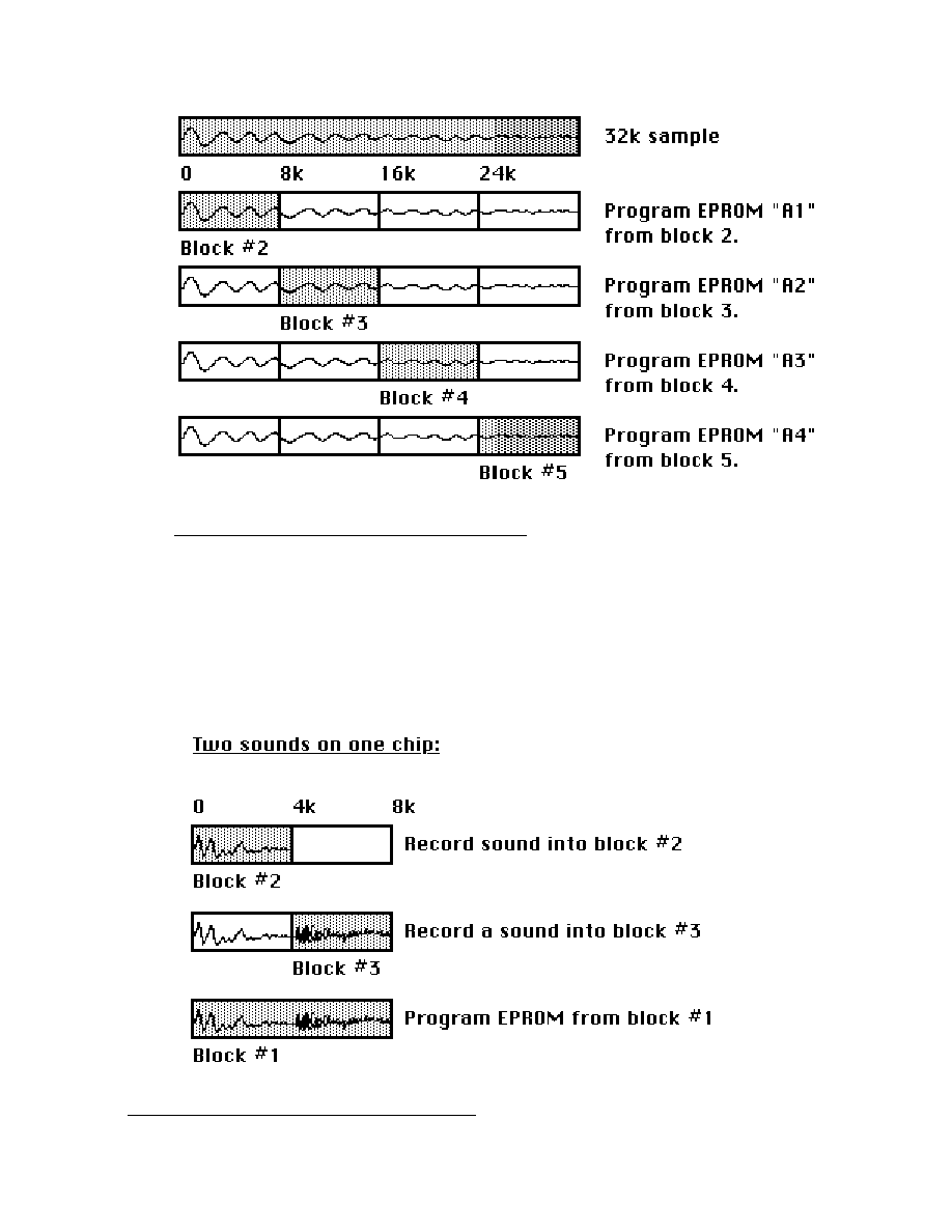
Figure
5
-
One
Sound
on
Four
Chips
EXAMPLE 3 - MULTIPLE SOUNDS ON ONE E P R O M
If you want to put two sounds on one chip for the PERC position in your DX (two
4k sounds on one 8k chip), there are at least two ways to do it. One way is to
record the separate sounds into the Prommer in two sequential blocks, and then
define a block that covers both of these and program the EPROM from this third
block as shown in figure 6.
Figure
6
-
Two
Sounds
on
One
Chip

Prommer User's Guide
EPROMs
34
Another way to do this is to program the block that will be the first of the two
sounds into your EPROM, and then set the
PROM
offset and program the
second sound into the second half of the EPROM. For example, let's say you
have two 4k sounds that you want to put on an 8k EPROM. Program the first
sound normally onto a 2764 with the PROM offset equal to zero. Since the
current block is only 4k in length, the programming process will only program the
first half of the EPROM, leaving the second half blank. Now, set the PROM offset
to 4k and program the second block into the same 2764.
(Don't forget to reset the PROM offset back to zero after you finish!)
PICTURE HERE : two sounds in one EPROM

Prommer User's Guide
Block Functions
35
Chapter
7
-
BLOCK
F U N C T I O N S
There are several functions available to manipulate blocks of memory in
the Prommer. The functions operate in the following way. Press the
appropriate function button until the display shows the desired function.
Next, select the correct parameters for the function to operate with, and
then press EXECUTE. Please notice that in
all Prommer displays,
whenever you see an asterisk (*), it means that you must press the
EXECUTE button in order to perform the indicated function.
COPYING B L O C K S
The contents of blocks may be copied from one place to another in
memory. Press the COPY BLOCK button:
1 COPY TO 2 *
The number on the left is the current block (source), and the number on
the right is the destination block for the copy operation. You can change
the destination block number with the number pad or the arrows. (To
change the source block, you will have to go to the SELECT BLOCK
display and change the current block and then come back to the COPY
BLOCK display.)
This function will copy the data in the currrent block into the destination
block when you press EXECUTE (if the destination block is not
protected). Only the sound data is copied - all parameters such as loop
points, transpose, etc. are unchanged in the destination block. The two
blocks must be equal in length - you will get an error message if you try to
copy to a block that is not the same size as the source:
NOT EQUAL S I Z E .
If the two blocks involved in the copy operation overlap, the overlapped
part of the source block will be changed by the data that is copied into the
secondary block.
EXCHANGING BLOCKS
There is also a function that will
exchange
the contents of two blocks of
memory. If you press the COPY BLOCK button again, the display will
read:
1 SWAP WITH 2 *
The number on the right (the secondary block) may be changed with the
number pad or the arrows.
This
swap
function will exchange the contents of two blocks of equal
length (blocks 1 and 2 in this example). As with
copy
, the swap function
only exchanges sound data - all other block parameters are unchanged.
In addition to being equal in length, the blocks must not overlap. If you try
to swap overlapping blocks you will see the error message:
BLOCKS O V E R L A P .
When an error message appears, press any key to return to normal
operation.

Prommer User's Guide
Block Functions
36

Prommer User's Guide
Block Functions
37
ERASING A B L O C K
You can erase the sound data in a block with the
erase
block
function.
Press the COPY BLOCK button again:
1 ERASE BLOCK *
At this point you may change the current block with the number pad or
the arrows. Press EXECUTE to erase the sound data memory in the
current block (all bytes equal to 0). Block parameters remain unchanged.
ERASING EVERYTHING
You can erase
all memory including all blocks, and reset all parameters to
their default values - press COPY BLOCK again:
ERASE ALL *
If
you
are
sure
you
want
to
erase
everything
, press EXECUTE now.
REVERSING S O U N D S
You can make a sound play backwards by reversing it. To access the
reverse
function press the REVERSE button:
2 REVERSE *
Pressing the EXECUTE button now will reverse the data in the current
block (displayed at the left). You can return the sound to normal by
reversing it once more.
NUMBER CRUNCHING
Notice that when the Prommer is executing a function the display reads:
BUSY. . . .
This means that it is busy making the calculations required to make the
change in the data. Since some of these functions require a
considerable amount of "number crunching" (calculation), they may take
from a few seconds to more than a minute to execute, depending on the
function and the amount of data involved. You can stop a function before
it is finished with the STOP button, but there is no way to start again at the
point where you stopped, so you would have to start from the beginning
if you wanted to continue.
WARNING
NOTE: Before using any of the following functions, it is advised that you
make a copy of your sound in another part of memory, if possible, since
the effects of some of these functions are not reversible.

Prommer User's Guide
Block Functions
38
BIT FUNCTION
The
bit function can be used for special effects or other purposes. Press
the REVERSE button again to see the bit display:
2 BIT - - - - - - - - *
The number on the left is the current block. The asterisk on the right
indicates that this is a function that requires you to press the EXECUTE
button before any action will be taken. The eight dashes correspond to
the eight bits in a data byte, with the most significant bit on the left. A
blinking cursor showing the position of the currently selected bit can be
moved left and right with the arrow buttons.
The bit function, when executed, will modify every byte of data in the
current block according to the image displayed in the following manner; If
there is a dash ("-") displayed (select with CLEAR button), there will be no
change to the bits at that position. If an "X" is displayed (+/- button) the
data at that position will be logically inverted. If a "1" or "0" is displayed
(select with 1 or 0 buttons), the bit at that position will set to one or to
zero, respectively. (See the table below).
Bit
display
Select
with:
Result
after
EXECUTE
-
CLEAR
No Change
X
+/-
Invert bit
1
1
Set bit to 1
0
0
Set bit to 0
One application of this function is to introduce distortions to a sound by
setting certain bits to one or zero, or by inverting bits.
2 BIT - X -1- - 01 *
Another application is phase inversion; by inverting only the most
significant bit (the sign bit) you can invert the polarity of a sound.
2 BIT X - - - - - - - *
If you have modified a sound with a bit pattern containing only "X"s and "-
"s you can return the sound to normal by applying the same pattern a
second time. If you have applied a pattern containing any zeros or ones,
there is no way to return to the original data unless you made a copy of
the block before starting.

Prommer User's Guide
Block Functions
39
DISPLAYING M E M O R Y
The Prommer will allow you to examine and modify memory one byte at a
time. Press the REVERSE button again and the
examine
memory
display will appear:
1, 4321 = 1 2 9 .
The number on the far left is the current block. The number just to the
right of the comma is an absolute memory address, and the data byte
located at that address is displayed at the far right. The arrows are used to
increment or decrement the address. The CLEAR button will reset the
address to the start of the current block.
The address is always displayed in decimal and may also be entered
numerically by pressing the [#] button. The data will blank out, and you
can now use the number pad to enter a different address.
Press the [#] button again to return to examining data.
DATA DISPLAY F O R M A T
The data may be displayed in one of three different formats - absolute
value, hexadecimal, or sign & magnitude.
To select the display format, press the PARAMETERS button:
DISPLAY ABS. V A L .
Use the arrows or the +/- button to rotate between the three formats.
Absolute value format (identified by a decimal point after the data) shows
the decimal value of the eight bit data in memory. Sign & magnitude
format interprets the lower seven bits of data as a decimal number and the
eighth bit as a sign (0=positive, 1=negative). This mode is useful for
examining sound data. Hexadecimal mode (number base 16) is handy for
examining MIDI data and is identified by the letter H to the right of the
data.
Press PARAMETERS again to return to examining memory.
MODIFYING MEMORY
In the absolute value and sign & magnitude display modes, you may
modify the data that is currently displayed by using the number pad and
the +/- button to enter a new value directly.
Note: The protect status of a block is NOT checked before data is
modified with this function.

Prommer User's Guide
Sound Modifications
39
Chapter
8
-
SOUND
MODIFICATIONS
The Prommer has several
sound
modification
features which change the data
stored in memory.
ENVELOPING A S O U N D
One of these is the
envelope
function which will modulate the current block with a
decay envelope. Suppose you have recorded a drum sound and there is a
sudden cut-off of the sound at the end of the block. You can use the envelope
function to make the cut-off more gradual. Press the ENVELOPE button to see
the display:
2 ENVELOPE *
Pressing the EXECUTE button now will modify the currrent block. However, you
will probably want to set the
envelope
parameters
before you go on.
ENVELOPE DECAY P A R A M E T E R S
Press the PARAMETERS button now to set the
decay
time
:
DECAY TIME= 3 3
Pressing the PARAMETERS button one more time will display the
decay
start
point :
START PT.= 0 / 1 0 0
The number pad and arrows may be used to change the envelope parameters.
Press the ENVELOPE button again to go back to the envelope display.
The decay of the envelope can be described as a linear decay from the specified
start point to the end of the current block. The start point is specified as a fraction
of the length of the current block - 0/100 means that the envelope will start at the
beginning of the sound, 99/100 means that it will start almost at the end of the
sound.
A low value for the decay time will give a fast cutoff, and a high value will provide a
long gradual envelope.
Applying an envelope to a block two or more times increases the effect and
makes the decay exponential rather than linear.
See Figure 8 for some examples of the effects of envelopes on sounds.
HOW TO GET AN ATTACK E N V E L O P E
In addition to a decay envelope, you can get the effect of an
attack
envelope
in
the following way: First reverse the block, then apply a decay envelope, and then
reverse the block a second time.
TECHNICAL NOTE ABOUT DECAY T I M E
For the technically inclined reader, the decay time can be defined as follows;
D=decay time, X starts at 255. The current address is set to the start point and is
incremented by one until it reaches the end of the block, while the linear
equivalent value of the sound data at the current address is multiplied by X/256,
and every D bytes, X is decremented by one (until it reaches zero).

Prommer User's Guide
Sound Modifications
40
PICTURE HERE : Figure 8 - Envelope example

Prommer User's Guide
Sound Modifications
41
MIXING SOUNDS IN M E M O R Y
The sounds in two blocks may be mixed together into one block. Press the MIX
BLOCKS button:
1 MIX WITH 2 *
The current block is displayed at the left and the secondary block is shown at the
right. You can change the secondary block with the number pad or the arrows.
Pressing EXECUTE now will mix the current block with the secondary block at the
currently set mix ratio (see below) and
store
the
result in
the
current
block
.
MIX RATIO
The two blocks can be mixed in equal parts, or a different
mix
ratio
may be set.
Press PARAMETERS to display the current mixing ratio:
MIX RATIO= 3 / 4
Use the number pad or the arrows to change the ratio numerator. The numerator
of the fraction (3 in this example) refers to the amount of the CURRENT block to
mix and the denominator (4 in this example) refers to the amount of the
SECONDARY block to mix. Notice that the denominator always equals four. The
numerator may range from zero to sixteen. If you mix two blocks at a mix ratio of
0/4, the secondary block will be copied into the current block at
half its original
volume level.
A
mix
ratio
of
4/4
will
mix
equal
parts
of both blocks.
RING MODULATION
Press the MIX BLOCKS button again until you see the RING MOD. display:
1 RING MOD. 2
The
ring
modulate
function is like the MIX function except instead of
summing
two
blocks together, the blocks are
multiplied
together and then scaled down,
causing an effect known as Ring Modulation. If you press EXECUTE now, the
current block will be multiplied together with the secondary block and the result
stored in the current block.
The current mix ratio also applies to blocks being ring modulated and can be set
by pressing the PARAMETERS button as described above.

Prommer User's Guide
Sound Modifications
42
STRETCHING AND SQUASHING
You can double the length of the current block with the
stretch
function. Press
the STRETCH button:
2 STRETCH *
When you press EXECUTE, this function will stretch the current block to twice its
original length. The block length parameter is doubled automatically. Bytes from
the original block are spread out to occupy every other address of the new block
and the spaces between are filled with the average value of the data on either
side.
WARNING: The protect status of the memory
following
the current block is NOT
checked before the stretch function is executed.
Press STRETCH again to access the
squash
function:
2 SQUASH *
This function is the opposite of stretch - it will shorten the current block to half it's
original length, copying every other byte of the original block to the new block.
The new block is located at the same start address as the original block and the
leftover part of the original block is not disturbed.
Press EXECUTE to perform the function.
When you play back a block that has been stretched, you will hear that the pitch is
an octave lower. Squashing a block will raise the apparent pitch by one octave.
You should understand that when you squash a block you will lose half of the
information contained in the original block, and that stretching it out again will only
fill in the gaps with approximated data. Squashing and then stretching a block will
act as a sort of low pass filter.

Prommer User's Guide
MIDI
43
Chapter
9
-
MIDI
MIDI is a standardized digital communication interface common to many electronic
musical instruments. MIDI commands and messages are transmitted serially over
a cable between MIDI transmitters and receivers. The commands include such
functions as Note-On, Note-Off, Pitch Bend, Program Change, etc.
The Prommer is capable of receiving and transmitting several types of MIDI
information. Note-On commands received by the Prommer from a keyboard, for
example, can play back sounds at a pitch relative to the note played. For a
complete description of how the Prommer implements MIDI, see appendix 3.
BASIC C H A N N E L
The Prommer may be set to receive voice messages on any one of sixteen MIDI
channels. To select the channel for the Prommer, press the MIDI CHANNEL
button. The display will show the current MIDI receive channel:
MIDI CHAN. = O M N I
OMNI means that the Prommer will recognize MIDI data on
all sixteen channels.
To select a single channel, use the number pad to enter a number from 1 to 16:
MIDI CHAN. = 1 2
If a single channel number is set, the Prommer will only recognize data that is
received on that channel. Enter zero or press CLEAR to reset to OMNI mode.
MIDI PITCH C O N T R O L
Press the MIDI CHANNEL button again to see the next parameter:
3 KEY. PITCH O N
The keyboard control of playback pitch may be toggled ON or OFF with the +/-
button. The current block is displayed on the left and may be changed at this time
with the number pad or the arrows.
The
keyboard
pitch
enable
option is provided so that each block may be set to
allow the MIDI controller (keyboard) to trigger the sound and control the playback
pitch, or to trigger the sound with the pitch control "turned off" so the sound will
always play at it's normal pitch regardless of which key is played. When the
keyboard pitch is enabled, middle C (MIDI note number 60) will play the sound in
the current block at its normal pitch (which is determined by the basic sample rate,
transpose, and fine tune values for the current block), and notes above or below
middle C will play the sound at a correspondingly higher or lower pitch.
MIDI E C H O
Press the MIDI CHANNEL button again to set the
echo
mode:
MIDI ECHO O F F
Use the +/- button to select one of three echo modes - ON, OFF, or SPL x.
MIDI echo ON will take everything that is received at the MIDI IN connector and
echo (retransmit) it through the MIDI OUT connector.
Echo OFF will not echo anything.
SPL is used as an abbreviation for spillover. Use the number pad or arrows to
change the spillover number.

Prommer User's Guide
MIDI
44
Spillover echo will retransmit all information except note-on messages. A note-on
message is only retransmitted (spilled over) if a block is currently in the process of
being played. This feature will allow you to connect two or more Prommers in
series and play them polyphonically from a MIDI keyboard. To do this, you need to
set the spillover number for each unit in the chain to the number of units
remaining "down the chain" from it. The spillover number is used to determine
how many note-ons to echo while a note is playing before "robbing" the Prommer
of its note and retriggering it with the latest note-on number. See figure 9 for an
example of using spillover echo.
EXAMPLE OF USING MULTIPLE PROMMER UNITS TOGETHER POLYPHONICALLY
By using spillover echo mode, many Prommers may be linked together to play
sounds polyphonically. Using MIDI cables as shown, connect the units together.
Set all units to the same MIDI channel, and set the spillover echo number for each
unit to the number of Prommers to the right of the selected one (as shown in the
picture). The last unit in the chain should have "ECHO OFF". Load the sound(s)
that will be played into the first unit in the chain and then execute a MIDI "DUMP
ALL" command to copy the sounds into the other units.
PICTURE HERE: Figure 9 - Spillover example

Prommer User's Guide
MIDI
45
MIDI BLOCK SELECT M O D E S
There are three basic MIDI modes of operation for the Prommer. Press the MIDI
MODE button to see the currently selected mode.
One of the following three messages will be displayed. The mode may be
changed by using the +/- button or the arrows.
MIDI ZONE M O D E
MIDI
zone
mode
is the most commonly used mode and can be used to allocate
different sections of the keyboard to different blocks (sounds). In this mode if a
MIDI note is received that is outside of the zone limits for the current block, the
limits of each other block are tested until a block is found that the note will fit in.
This new block becomes the current block and is played.
This mode may be used to assign different blocks to different areas of the
keyboard or even to single MIDI note numbers.
BLOCK=CHAN. M O D E
Block-equals-channel
mode
uses the received MIDI channel number to select the
current block. The basic MIDI channel should be set to OMNI in order to use this
mode.
VELO. ZONE M O D E
Velocity
zone
mode
is similar to MIDI zone mode, except the zone limits are
tested against the note-on
velocity
rather than the note-on
number , so the block
is changed according to the velocity of a note.
Z O N E S
Each block may be assigned to a particular range of note numbers or velocity
values. This range is called a
zone
, and is defined by its upper and lower limits.
To view the zone limits for the current block, press the PARAMETERS button
now:
1 LOWER LIM.= 0
Continue pressing the PARAMETERS button to switch between upper and
lower limits:
1 UPPER L I M . = 1 2 7
The arrows may be used to change the current block (displayed at the left). The
number pad may be used to set the limit value. The CLEAR button will reset the
limit to a default value (0 for lower limits, 127 for upper limits). Press the MIDI
MODE button again to get back to the mode display.
The limits may also be set with an external MIDI keyboard connected to the
Prommer. Press
and
hold
the PARAMETERS button so that the display shows
the limit you want to set and then press a key on the keyboard. The limit will now
be set to the value of the key just pressed. The range of limits is 0 to 127 which is
also the range of MIDI notes.
If you want a block
not to play by MIDI, set both the upper and lower limits for that
block to zero.
To set normal operation, select MIDI zone mode and set the lower limits for all
blocks to zero, and set all upper limits to 127. This will enable all blocks to play via
MIDI and the current block will not be changed by MIDI notes. See appendix 1 for
a few examples of the many ways to use MIDI zones.
PITCH BENDING

Prommer User's Guide
MIDI
46
The pitch bender on a MIDI controller can be used to control the playback pitch of
a block. Press the BEND RANGE button :
BEND RANGE = 0
To enable the pitch lever (pitch wheel), use the arrows or number pad to enter a
non-zero value for the bend range. Bend range is specified in semitones, so a
value of 12 will give one octave of bend (up or down). The maximum bend range
is 36 (three octaves).
MIDI VELOCITY AND PRESSURE R O U T I N G
MIDI note-on velocity may be used to control the loudness level or the filter
frequency during playback. To select a destination for MIDI velocity, press the
BEND RANGE button again:
VELOCITY V C F
Use the arrows or the +/- button to select velocity OFF, VCA (Voltage
Controlled Amplifier), or VCF (Voltage Controlled Filter). Increasing velocity will
increase the volume level or raise the output filter frequency.
MIDI pressure (after-touch) information may also be used to control volume level
or filter frequency. Press the BEND RANGE button one more time:
PRESSURE O F F
Use the arrows or the +/- button to select the pressure destination (OFF, VCA,
or VCF).
Both Channel Pressure and Polyphonic Key Pressure are recognized, and if
both are transmitted by the controller, the Prommer will try to respond to both
types. If possible, enable only one type of pressure at a time on the transmitter.
REMOTE BLOCK S E L E C T I O N
The program (patch) selection controls on a MIDI controller may be used to select
the current block of the Prommer. Press the BEND RANGE button again:
PROG. CHANGE O F F
Use the arrows or the +/- button to turn the program change enable ON or OFF.
When program change is
on
, selecting a program number on the controller will
select the block with the same number on the Prommer. Numbers higher than
sixteen will set the block by modulo 16 (program #17 selects block #1, program
#18 selects block #2, etc.).

Prommer User's Guide
MIDI
47
MIDI DATA T R A N S F E R
MIDI may be used in various ways to transfer sound data between machines using
MIDI's
system
exclusive
feature. The Prommer supports two different system
exclusive formats used for transferring sounds. The first is used only for
transferring sounds between two Oberheim Prommers and transfers all
parameters and sound data associated with a block. The other format is a
"universal" type of sample dump based on a proposed standard that transfers
sound data in linear format and includes only the following parameters: sample
number, sample rate, sample length, loop start address, loop end address, and
loop type.
PROMMER SOUND D U M P
The Prommer sound transfer uses a single MIDI cable in an "open loop" system.
To transfer a sound from one Prommer to another, connect the MIDI cable from
MIDI Out of the sending unit to MIDI In of the receiving unit. Press the BLOCK
DUMP button:
1 SYSTEMX D U M P *
The number on the left is the current block which is the block that will be
transmitted in Prommer system exclusive format when you press EXECUTE. The
dump will transfer all data associated with the current block including sound data,
block number, block start address and length, loop start and end points, zone
limits, sample rate, playback mode, transpose, fine tune, filter frequency, and
protect, emphasis, and MIDI pitch disable status.
Press EXECUTE to start the transmission. The display should read:
STOP TO CANCEL. . .
Pressing the STOP button will interrupt the data transfer. The receiving Prommer
will automatically accept the data as it comes in unless the current block is
protected, or a recording is in progress. There is no interruption in regular
operation while the data is being received, except that if a sound is playing, you
will hear it slow down considerably during reception.
You can transmit all 16 blocks in Prommer System Exclusive format. Press the
BLOCK DUMP button again:
SYSX DUMP ALL *
System exclusive
Dump
All will transfer all blocks and block parameters over MIDI.
Notice that if there are overlapping blocks defined, some data will be transmitted
more than once. Since it takes several seconds to transmit sound data, a system
exclusive dump-all may take several minutes if there is much overlapping data.
After all blocks have been transmitted, global parameters - MIDI mode, Bend
Range, Program Change Enable, MIDI Channel, Velocity and Pressure
Destinations, and External Trigger parameters - are also transferred.
Press EXECUTE to start the transfer:
STOP TO CANCEL. 1
The number displayed on the right is the current block and you will see it
automatically incremented as blocks are transmitted one at a time.
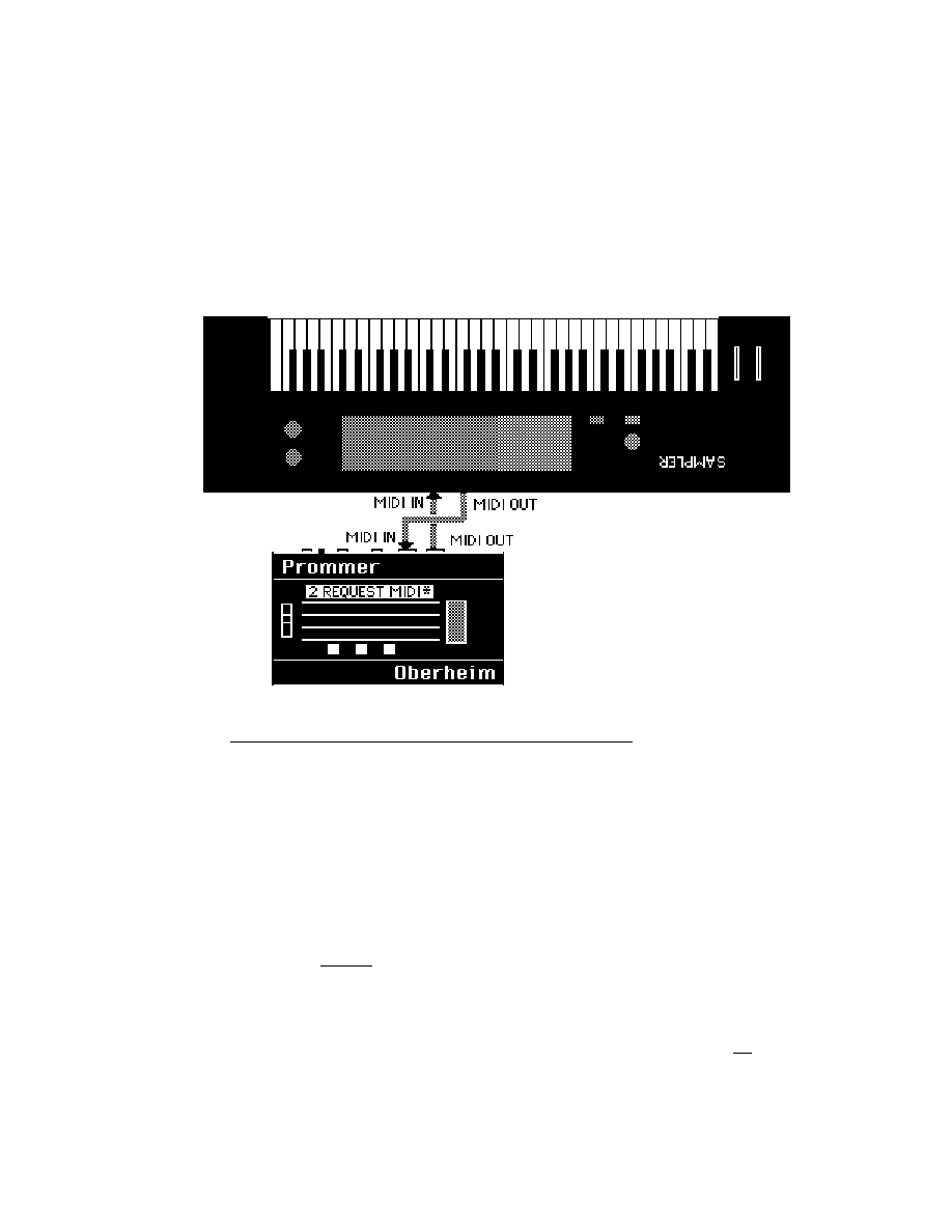
Prommer User's Guide
MIDI
48
UNIVERSAL SAMPLE D U M P
The Universal sample dump system is designed to use MIDI In and MIDI Out on
each machine to provide "handshaking" between the two machines involved in
the transfer (see figure 10). Although both connections are not absolutely
necessary, for improved speed and error correction this "closed loop" system
may be used. If a single connection is used ("open loop") the cable should be
connected from the sender's MIDI Out to the receiver's MIDI In.
Figure
10
-
Closed
Loop
Communication
To prepare to transmit a sample in universal format, press the SOUND DUMP
button again:
2 MIDI DUMP *
Press EXECUTE to start transmission of the current block. If a closed loop system
is used and the receiving machine is not ready to accept data, it may send a
CANCEL command and the Prommer will stop transmitting. Otherwise, the
Prommer will continue sending until the transmission is complete.
To
receive
Universal MIDI data, the Prommer must be prepared to accept the data.
Press the BLOCK DUMP button one more time:
2 REQUEST M I D I *
After you press EXECUTE, the Prommer will turn MIDI Echo
off and transmit a
"Dump Request" command, requesting the sample with the same number as the
current block. The Prommer will then wait for incoming data. If a closed loop
system is being used and the other machine is not ready to transmit, it may send a

Prommer User's Guide
MIDI
49
CANCEL command over MIDI and the Prommer will stop waiting and return to
normal operation, restoring whatever echo mode was previously set.
The Prommer will also quit if the current block is protected or if you press the
STOP key. If an open loop system is used, after pressing EXECUTE to start the
REQUEST MIDI function, you must start transmission on the other machine by
pressing the proper switches. The sample number transmitted by the other
machine is ignored and the incoming data is stored in the current block.
MIDI DATA S T O R A G E
Another feature of the Prommer is the ability to store MIDI data in memory
exactly
as it is received. This is useful for storing synthesizer patches that are transmitted
in their own MIDI system exclusive format. Press the RECEIVE DATA button to
prepare to receive MIDI data in the current block:
3 RECEIVE D A T A *
Be sure the current block is long enough to receive the expected amount of data.
When you press EXECUTE to start receiving, you have about five seconds to
start transmitting from your synthesizer. Any time during reception, if five
seconds pass with no data received over MIDI, the Prommer will automatically
cancel the receive data mode. You may also cancel receive mode by pressing the
STOP button. The display will then show the number of bytes that were
received:
OK- 1234 B Y T E S .
This number is stored as two bytes in the first two memory locations of the current
block. The actual data received starts at the third location.
MIDI DATA TRANSMISSION
To retransmit this kind of MIDI data
do
not use the system exclusive dump - use
the
transmit
data
function. Press the RECEIVE DATA button again:
1 TRANS DATA *
Warning
- do not try to transmit data that was not originally received using the
RECEIVE DATA function ! Sending non-MIDI data out over MIDI may have
unpredictable results on any units connected to the Prommer's MIDI Out
connector.
When you are ready to transmit, press the EXECUTE button and the first two
bytes of the current block will be read to determine the number of bytes to
transmit. The data will now be transmitted starting with the data at the third
address of the current block. After transmission is complete, the display will
indicate the number of bytes that were transmitted.
RECEIVE / TRANSMIT DATA E X A M P L E
The Prommer may be used with any synthesizer or drum machine that can
transmit and receive program (patch) data on MIDI to save and recall patches on
EPROMs. Each type of machine will vary slightly, but the procedure is basically
the same as described here with the Oberheim Matrix-12 synthesizer as an
example.
The amount of data transmitted in a "Patch Dump" will vary from machine to
machine, so before starting, make sure there will be enough room in the current
block to receive all the data - set block #1 to address=0 and length=64k.

Prommer User's Guide
MIDI
50
With MIDI Out of the Matrix-12 connected to MIDI In of the Prommer, select the
RECEIVE DATA function on the Prommer. When the synthesizer has been
prepared to transmit its patches (Master page / MIDI / SEND ALL ), press
EXECUTE on the Prommer. You now have five seconds to start transmission of
the Matrix-12 patches by pressing the START button. Now, just wait until the
synthesizer has completed its transmission, and then when no MIDI data is
received after five seconds, the Prommer will cancel the Receive mode
automatically.
Note: If your synthesizer sends active sensing status or controller data
continuously on MIDI, the Prommer won't stop receiving until the current block is
full, unless you press STOP after the patch dump is complete. If possible, turn off
active sensing and controllers before starting a patch dump to the Prommer.
When the dump is complete, or the current block is full, the display will show the
number of bytes received. Add two to this number to get the total number of
bytes you need to save on EPROM(s). In the case of the Matrix-12, the display
read:
OK - 64207 B Y T E S .
Add 2 to get 64209, and divide this number by 1024 to see how many "k" of
EPROM space will be needed. This amount of data (62.7k) will require a single
64k EPROM (27512), two 32k EPROMs (27256) or four 16k EPROMs (27128),
etc.
Let's assume that you have two blank 27256's handy, and will use them to store
your Matrix-12 patches. Set up two more blocks in the Prommer; Block #2
starting at address 0 with length = 32k, and Block #3 starting at address 32k with
length = 32k.
Set the EPROM type to 27256 and program block #2 into one of the EPROMs
and label it "Matrix-12 patches part 1 of 2". This EPROM now contains the first
half of the patch data and the total number of bytes in the patch dump coded into
its first two bytes. Now, program block #3 into the other EPROM and label it
"Matrix-12 patches part 2 of 2". This EPROM contains the final part of the patch
data.
To load the patches back into the synthesizer, the process is basically reversed.
Set up three blocks in the Prommer; Block #1 at address 0 with length = 64k,
block #2 at address 0 with length = 32k, and block #3 at address 32k with length =
32k.
Select block #2 and load the data from the EPROM labelled "part 1 of 2". Select
block #3 and load "part 2 of 2".
Connect the Prommer MIDI Out to the Matrix-12 MIDI In. Make sure the
synthesizer is ready to receive system exclusive patch data and then select block
#1 as the current block on the Prommer. Select the TRANSMIT DATA function
and press EXECUTE. The Prommer then will read the first two bytes of the
current block to find out how many bytes of data to transmit, and then will transmit
the data over MIDI to the synthesizer exactly as it was originally received.
Note: The Prommer does not save any timing information with received data, and
will retransmit it as fast as possible. To avoid some of the problems this might
cause in other machines, a 20 millisecond pause is inserted after every EOX
(F7H) byte that is encountered during transmission. This gives the receiving
machine time to do any necessary computations between multiple system
exclusive messages.

Miscellaneous
Prommer User's Guide
Information
51
Chapter
10
-
MISCELLANEOUS
INFORMATION
SOFTWARE REVISION N U M B E R
To display the current version of software that is installed in your Prommer,
immediately after turning on the power, press and hold the 3, 5 and 7 buttons.
BATTERY BACKUP M E M O R Y
The random access memory (RAM) in the Prommer is powered by a lithium battery
when the AC power is off. So, whatever sounds were in the Prommer when you
last turned off the power will still be there when you turn the power on again. The
battery should last more than a year before it starts to run down, but when the
battery does eventually fail, the Prommer will lose data when the power is turned
off and the next time the power is turned back on, the display will read:
CHECK B A T T E R Y
The CHECK BATTERY message will appear immediately after turning on the AC
power if there has been a major loss of memory. When this message appears,
contact your local Oberheim Authorized Service Center to get a replacement
battery installed.
IN CASE OF A P R O B L E M
On rare occasions computer based products like the Prommer will unexpectedly
"lock up" or cease functioning. This can be caused by surges in the AC power
line or static electricity shocks (especially static shocks caused when touching the
EPROM socket). If the Prommer locks up, it can usually be restarted without any
loss of memory by simply turning the power off and then on again. If the unit
remains locked up, there is a failsafe method of restarting it - hold the CLEAR
button down while turning on the power. ALL data in memory will be erased and
all parameters will be set to default values. Since this erases all sounds in memory,
it is recommended that you save your important sounds and other data on
EPROMs or some other permanent storage device soon after recording them.
If the Prommer seems to behave in an otherwise unexpected manner, be sure to
check all parameters that could be related to the problem before assuming that it
is broken. If there is an obvious problem, contact your nearest Oberheim
Authorized Service Center.
TEST P R O G R A M S
There are some functions not normally available in the Prommer that are accessed
in the following way:
1. Turn off the AC power.
2. Hold down both the PLAY and RECORD buttons.
3. Turn the power on again.
As long as the PLAY and RECORD buttons are held down the display will read:
TEST PROGRAMS. . .

Miscellaneous
Prommer User's Guide
Information
52
After releasing all switches, the first of eight
test
progams
used to verify operation
of the Prommer will be displayed. Most of these are of interest only to the service
technician, however the first one may be used to set the brightness of the
vacuum fluorescent display:
DISPLAY I N T E N S .
Press the arrows to increase or decrease the intensity of the display. When the
intensity is at an acceptable level, press STOP. The Prommer will remember this
value and use it to set the brightness of the display in the future (until you change
the value again).
You may press EXECUTE to start any of the tests, or just keep pressing STOP
until the display reads:
OBERHEIM P R O M M E R
At this point, normal operation is resumed.
Important note: Be sure that the PROM socket on the front panel is
empty
before
executing any of the test programs.
For more information regarding these test programs, please refer to the Prommer
Service Manual.
ABOUT BYTES AND S A M P L E S
The term
byte
is used frequently in this guide and should be explained for those
unfamiliar with computer teminology. A byte is defined as a group of eight
bits
of
information. A bit is a binary digit that has only two possible values - zero or one. A
byte has 256 (2 to the 8th power) possible values, or combinations of ones and
zeros.
Memory in the Prommer is arranged in bytes. Each byte of memory can be
located by a unique 16 bit address. The range of addresses is from zero to
65535 (2 to the 16th power possible addresses).
When a sound is sampled by the Prommer, each sample (one byte per sample) is
stored at a new memory address. Each sample is coded into eight bits, and the
number stored as a byte represents an instantaneous voltage level
corresponding to the input signal at the time the sample was taken. Upon
playback, these numbers are read back out of memory, and converted back into a
voltage, one at a time at a steady sample rate.
If you could look directly into a memory location at random you might see the
following group of eight bits :
10011100
This binary number could be interpreted in several different ways. The decimal
equivalent to this number is 152, in sign & magnitude form it is -28, and in
Hexadecimal it is equal to 9C. All three interpretations are equally valid.
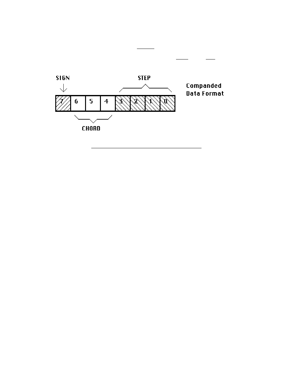
Miscellaneous
Prommer User's Guide
Information
53
COMPANDED D A T A
The Prommer stores
samples
in a sort of Sign/Magnitude format known as
companded. The most significant bit is the sign and the other bits represent the
magnitude of the sample in two parts - the
chord
and the
step
values.
Figure
11
-
Companded
Data
Format
Briefly, the chord value represents one of eight possible ranges of output levels,
each range being twice as large as the next lowest. The step value represents
one of 16 equal divisions within the selected chord.

Miscellaneous
Prommer User's Guide
Information
54

Prommer User's Guide
Summary of Functions
55
Oberheim Prommer - Summary of Functions
SELECT BLOCK
Select the current block number (1 - 16).
-parameters-
BLOCK ADDRESS - Select the beginning memory address for the current block.
BLOCK LENGTH - Select the length of the current block.
BLOCK PROTECT - Select protect status for the current block.
SAMPLE RATE
Select the sample rate for recording (12kHz, 16kHz, 24kHz, 32kHz).
-parameters-
RECORD TIME - Display the recording time available in the current block at the
selected sample rate.
RECORD TRIGGER THRESHOLD
Select the level of sound that will trigger recording ( -45 - 0 dB).
T R A N S P O S E
Select the playback transpose amount for the current block (-48 - +48
semitones).
FINE TUNE
Select the playback fine tune amount for the current block (-127 - +127).
SET FILTER
Select tracking filter or fixed filter for playback. For fixed filter select filter value (1 -
255).
PLAY MODE
Select playback mode (Normal, Gated, Loop, Gated/Loop).
-parameters-
LOOP START POINT - Select address offset for beginning of playback loop.
LOOP END POINT - Select address offset for end of playback loop.
EXTERNAL TRIGGER
Select external trigger (On/positive trigger, On/negative trigger, Off).
E M P H A S I S
Select Record and Playback emphasis (On, Off).
IDLE BYPASS
Select Idle Bypass mode (On, Off).
COPY BLOCK
Select destination block for copy operation. Press [EXECUTE] to copy.
SWAP BLOCKS
Select secondary block for swap operation. Press [EXECUTE] to swap.
ERASE BLOCK
Press [EXECUTE] to set all bytes of the current block to zero.
ERASE ALL
Press [EXECUTE] to clear ALL of the memory in the Prommer and reset default
parameters.

Prommer User's Guide
Summary of Functions
56
R E V E R S E
Press [EXECUTE] to reverse the order of the current block.
BIT - - - - - - - - *
Use arrows to move cursor. Use [0], [1], [CLEAR], [+/-] keys to select pattern for
each bit. Press [EXECUTE] to mask memory with displayed pattern (current block
only).
EXAMINE MEMORY
Display memory. Address shown is absolute memory address. Use number pad
to modify data (except in HEX display mode). Use arrows to change address or
press [#] and enter address directly.
-parameters-
DISPLAY MODE - Select data display mode for examine function (Hexadecimal,
Sign & magnitude, Absolute).
E N V E L O P E
Press [EXECUTE] to calculate an envelope for the current block.
-parameters-
DECAY TIME - Select decay time for envelope operation (0 - 99).
START POINT - Select envelope start point (0/100 - 99/100).
MIX BLOCKS
Select secondary block to mix with the current block. Press [EXECUTE] to add
blocks together in the current block.
-parameters-
MIX RATIO - Select the mix ratio between the blocks to be mixed :
Current Block / Secondary Block (0/4 - 16/4).
RING MODULATE BLOCKS
Select secondary block to modulate with the current block. Press [EXECUTE] to
multiply blocks together with the scaled result in the current block.
-parameters-
MIX RATIO - Same as for mixing blocks.
STRETCH BLOCK
Press [EXECUTE] to stretch the current block to double its original size,
averaging data to fill in new bytes.
SQUASH BLOCK
Press [EXECUTE] to squash the current block to half its original size, discarding
every other byte.
SELECT PROM
Use arrows to select appropriate EPROM or PROM type.
-parameters-
PROM OFFSET - Select EPROM address offset in 1K increments.
CHECK ERASURE
Press [EXECUTE] to test EPROM for erasure.
COMPARE DATA
Press [EXECUTE] to compare EPROM data with data in current block.
PROGRAM PROM
Press [EXECUTE] to program EPROM with data from the current block.
PROGRAM LINEAR

Prommer User's Guide
Summary of Functions
57
Press [EXECUTE] to program EPROM in linear format with data from the current
block.
PROGRAM SETUP
Press [EXECUTE] to program EPROM with all block and playback parameters for
entire unit. Data requires less than 1k of storage on EPROM.
LOAD DATA
Press [EXECUTE] to load data from EPROM into current block.
LOAD LINEAR
Press [EXECUTE] to load linear data from EPROM and convert to companded in
the current block.
LOAD SETUP
Press [EXECUTE] to load block parameters, etc. for entire unit from EPROM.
RUN PROGRAM
Hold PARAMETERS button and press [EXECUTE] to run 6809 program starting
at the first address of current block. Press [EXECUTE] only to run program out of
expansion EPROM (internal).
MIDI CHANNEL
Select basic MIDI channel for reception (OMNI, 1-16).
KEY PITCH ENABLE
Select MIDI pitch control of playback (On, Off) for current block.
MIDI ECHO
Select echo of incoming MIDI over MIDI OUT (On, Off, Spillover N [1
≤
N
≤
99] ).
MIDI MODE
Select MIDI playback mode (Keyboard zone, Velocity zone, Block=Channel).
-parameters-
ZONE UPPER LIMIT - Select upper MIDI zone limit for current block.
ZONE LOWER LIMIT - Select lower MIDI zone limit for current block.
BEND RANGE
Select the bend range for MIDI pitch wheel controller (0 - 36 semitones up/down).
V E L O C I T Y
Select destination for MIDI Note On velocity (Off, VCA, VCF).
P R E S S U R E
Select the destination for MIDI pressure (Off, VCA, VCF).
PROGRAM CHANGE
Select MIDI program change control of current Block number (On, Off).
SYSTEM EXCLUSIVE DUMP
Press [EXECUTE] to dump all sound data and parameters in the current block
over MIDI in Prommer system exclusive format.
SYSTEM EXCLUSIVE DUMP ALL
Press [EXECUTE] to dump all blocks and parameters over MIDI in Prommer
system exclusive format.
MIDI DUMP

Prommer User's Guide
Summary of Functions
58
Press [EXECUTE] to transmit the current block in "universal" MIDI linear sample
format.
REQUEST MIDI
Press [EXECUTE] to transmit a "dump request" and wait for incoming "universal"
MIDI sample data.
RECEIVE DATA
Press [EXECUTE] to enable transfer of MIDI data directly into the current block.
Function will time out after five seconds of inactivity. First two bytes of block will
contain the number of bytes received.
TRANSMIT DATA
Press [EXECUTE] to transfer data in the current block directly out over MIDI. First
two bytes of block must contain the number of bytes to transmit.
R E C O R D
Press RECORD and PLAY to record sound into the current block.
P L A Y
Press PLAY to play the sound in the current block.
S T O P
Press STOP to halt sound playback, or any operation in progress.

Prommer User's Guide
Appendix 1 - Examples
59
Prommer Application
Examples

Prommer User's Guide
Appendix 1 - Examples
60
APPENDIX 1 - PART A
DRUM MACHINES AND E P R O M S
One of the primary reasons for Oberheim's introduction of the Prommer was the
demand by DMX and DX owners for a way to create new sounds for their drum
machines. This section of the User's Guide will try to explain how the Prommer
can help you do that.
Basically, the process of creating a new drum machine sound is very simple;
sample a sound with the Prommer, burn an EPROM, and put the EPROM in the
drum machine. However, there are some complications to this process.
You may want to modify the sound before burning an EPROM, or you may want to
put two sounds on one EPROM. You may want to tailor the sound for a particular
type of drum machine voice circuit, or you might even need to modify the drum
machine voice configuration to match the desired drum sound.
If you own a drum machine other than an Oberheim, you need to find out whether
or not it uses individually replaceable sound chips, what sort of data format is
used, and what the capacities of the sound chips are. If your machine does not
use individual sound chips that are pin-compatible with any of the PROMs listed in
appendix 2, you will not be able to use the Prommer to make new sound chips.
The Prommer is also limited to programming only 8-bit data formats (companded
or linear). If your machine uses 8-bit linear format, see the chapter on EPROMs
for information on how to burn a chip in linear format. All Oberheim drum
machines use companded format data.
If you own a DX or DMX, see the tables in this section for information on
suggested sample rates and EPROM capacities for different drum voices.
1.
Sampling
a
sound
If you are going to record a live sound with a microphone, find a quiet place to
work, (with as little background noise as possible) and connect the microphone to
the Mic. Input of the Prommer. If you are recording from tape or disk, you can use
the Line Input. After selecting the appropriate sample rate, monitor the output of
the Prommer with the Idle Bypass
off and set the record level.
Select a block and set its length to match the capacity of the drum voice you
intend to use for your new sound.
Now, record the sound and play it back. If neccessary, record the sound again
until it sounds right. If the sound is slightly too long for the block, you may use the
envelope function to reduce any sudden cutoff, use a slower sample rate, or you
may have to consider using a different type of drum voice with a greater capacity.
2.
Burning
an
EPROM
Once you have a sample that you are satisfied with, you can program it into an
EPROM (or multiple EPROMs). Handle EPROMs with care and be certain to set
the Prommer for the same type of EPROM that you will be using. (If you have a
linear format drum machine, don't forget to use the Program Linear function.)
Another consideration when making sound chips is that some DX and DMX
voices have a hardware circuit that creates an envelope. This will affect the sound
in such a way that the sound you heard on the Prommer will not neccessarily be
the same on the drum machine. The best type of drum voice for playing Prommer
sounds is one without any enveloping, and with a wide tuning range.

Prommer User's Guide
Appendix 1 - Examples
61
DX and DMX standard EPROM types
DX Note: DX voices have a wider tuning range than most DMX voices.
V o i c e
EPROM
Capacity
Sample rate
Comments
DX Bass
2764
8k
24kHz
3 volume levels, envelope
DX Snare
2764
8k
32kHz
3 volume levels
DX Hi-hat
2764
8k
24kHz
Envelope on 1 & 2
DX Tom
2764
8k
12kHz-32kHz
3 Pitches
DX Cymbal
(DX serial #D4441 & lower)
2764 (x4)
32k
24kHz
Uses 4 EPROMS for 32k total
3 volume levels
DX Cymbal
(DX serial #H45001 & higher)
27256 (x2)
64k
24kHz
Uses two 32k ROMs - 2 sounds
1 & 2 - two volume levels
DX Perc
2764
8k
24kHz
2 sounds on 1 EPROM (4k each)
DMX
DMX Bass
2732
4k
24kHz
3 volume levels, envelope
DMX Snare
2732
4k
32kHz
3 volume levels
DMX Hi-hat
2732
4k
24kHz
Envelope on 1 & 2
DMX Toms
(old type)
2732
4k
12kHz
3 Pitches, envelope
DMX Toms
MK II Voice
2764
8k
12kHz
Envelope, jumpers select one or two
EPROMS, 2732 or 2764
DMX Cymbal #2
2732 (x8)
32k
24kHz
8 EPROMs for two16k sounds
DMX Cymbal #3
2764 (x8)
64k
24kHz
8 EPROMs for two 32k sounds
DMX Perc1
2732
4k
24kHz
2 sounds on one EPROM (2k each)
DMX Perc2
2732
4k
16kHz
2 sounds on one EPROM (2k each)
Note: Voices with a hardware envelope are not suitable for most sounds sampled with the Prommer. The
envelope will cut off about half of the sound, making only very percussive sounds usable.

Prommer User's Guide
Appendix 1 - Examples
62
Linn 9000
Note: All Linn 9000 sound chips are 8k (2764 type) EPROMs. All voices have a wide tuning range,
sample rates of 24kHz or 32kHz should be OK.
Voice board name
Individual outputs
Sound Length
# of chips
Notes
BASS / SNARE
Sidestick
8k
1
Snare
8k
1
Bass
8k
1
HI-HAT
Hi-hat
16k
2
Adjustable decay envelope
TOM-TOMS
Tom 4
8k
2
2 identical chips used for
Tom 3
...
...
alternating playback,
Tom 2
...
...
Filter envelope, 4 pitches.
Tom 1
...
...
CYMBALS
Ride 2
32k
4
Ride 1
32k
4
CYMBALS
Crash 2
48k
6
2 pitches
Crash 1
...
...
CONGAS
Conga 2
8k
2
2 ident. chips, 2 pitches,
Conga 1
...
...
Filter Envelope
PERCUSSION
Claps
8k
1
Cowbell
8k
1
Cabasa
8k 1
Tamborine
8k 1

Prommer User's Guide
Appendix 1 - Examples
63
Linn Drum
Note: All Linn Drum sound chips are 4k (2732 type) EPROMs. The basic sample rate is approximately
24kHz and not individually tunable per voice with the exception of the Snare, Toms, and Congas
No. of EPROMs /
Block size
Drum Voice
Location
Comments
1
4k
Bass drum
BASS
2 volume levels
1
4k
Cabasa
CBSA
2 volume levels
1
4k
Claps
CLPS
2
8k
Conga
CGA1-2
2 tunable pitch levels
1
4k
Cowbell
CWBL
8
32k
Crash Cymbal CRS1-8
4
16k
Hi-hat
HAT1-4
3 levels - 1 "open" (no envelope), 2
8
32k
Ride Cymbal
RID1-8
2 volume levels
1
4k
Side stick
SSTK
1
4k
Snare
SNAR
3 volume levels
(Side stick and Snare are
tunable together)
1
4k
Tamborine
TAMB
2 volume levels
2
8k
Tom
TOM1-2
2 tunable pitch levels
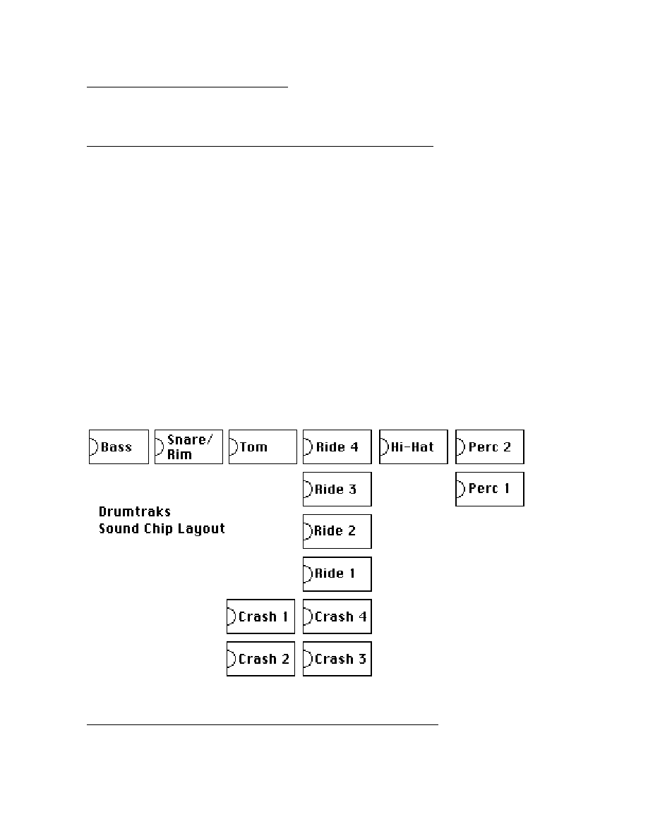
Prommer User's Guide
Appendix 1 - Examples
64
Sequential Circuits, Inc. Drumtraks
With the exception of the Bass drum chip which is a 2732 type, all EPROMs in the Drumtraks are 2764
types.
Channel
Standard Voice
EPROMs
Tuning Range
Notes
1
Bass
2732
7.7kHz-18kHz
Single 4k sound.
2
Snare/
1/2 2764
8.6kHz-22kHz
Two sounds on one 8k chip - First 4k
Rimshot
1/2 2764
12kHz-22kHz
is Snare, second 4k is Rimshot.
3
Tom 1
2764
2.6kHz-13kHz
Same 8k chip plays at two different
Tom 2
2.3kHz-13kHz
pitches.
4
Crash cymbal
4 x 2764
4kHz-25kHz
One 32k sound on four 8k chips.
Ride cymbal
4 x 2764
5.5kHz-25kHz
One 32k sound on four 8k chips.
5
Closed Hi-Hat
2764
8.3kHz-16kHz
Closed Hi-Hat is open Hi-hat with
Open Hi-Hat
envelope.
6
Claps/
1/2 2764
4kHz-14kHz
Two sounds on one 8k chip - First 4k
Tamborine
1/2 2764
4kHz-14kHz
is Claps, second 4k is Tamborine.
Cowbell/
1/2 2764
5kHz-25kHz
Two sounds on one 8k chip - FIrst 4k
Cabasa
1/2 2764
4kHz-14kHz
is Cowbell, second 4k is Cabasa.
Figure 12 - S.C.I. Drumtraks

Prommer User's Guide
Appendix 1 - Examples
65
SIMMONS DRUM MACHINES
All Simmons drums that use digital drum sounds (EPROMs) use 8 Bit Linear data
format. At the date of this writing, the following Simmons machines have actually
been tested at Oberheim for compatibility with the Prommer.
SIMMONS S D S - 1
The SDS-1 is a drum pad with an EPROM sound generating circuit built into it. A
switch selects either an 8k sound or a 16k sound (2764 or 27128). As with all
Simmons machines, the data format is linear and several controls are available for
changing the playback parameters of pitch, envelope, etc.
SIMMONS S D S - 9
The SDS-9 has provisions for three digital sound chips (Linear Format) played
with the Snare, Rim A and Rim B controls. The chips may be 2764 or 27128
types (8k or 16k) and several controls are available for modifying the playback
parameters of the sounds.

Prommer User's Guide
Appendix 1 - Examples
66
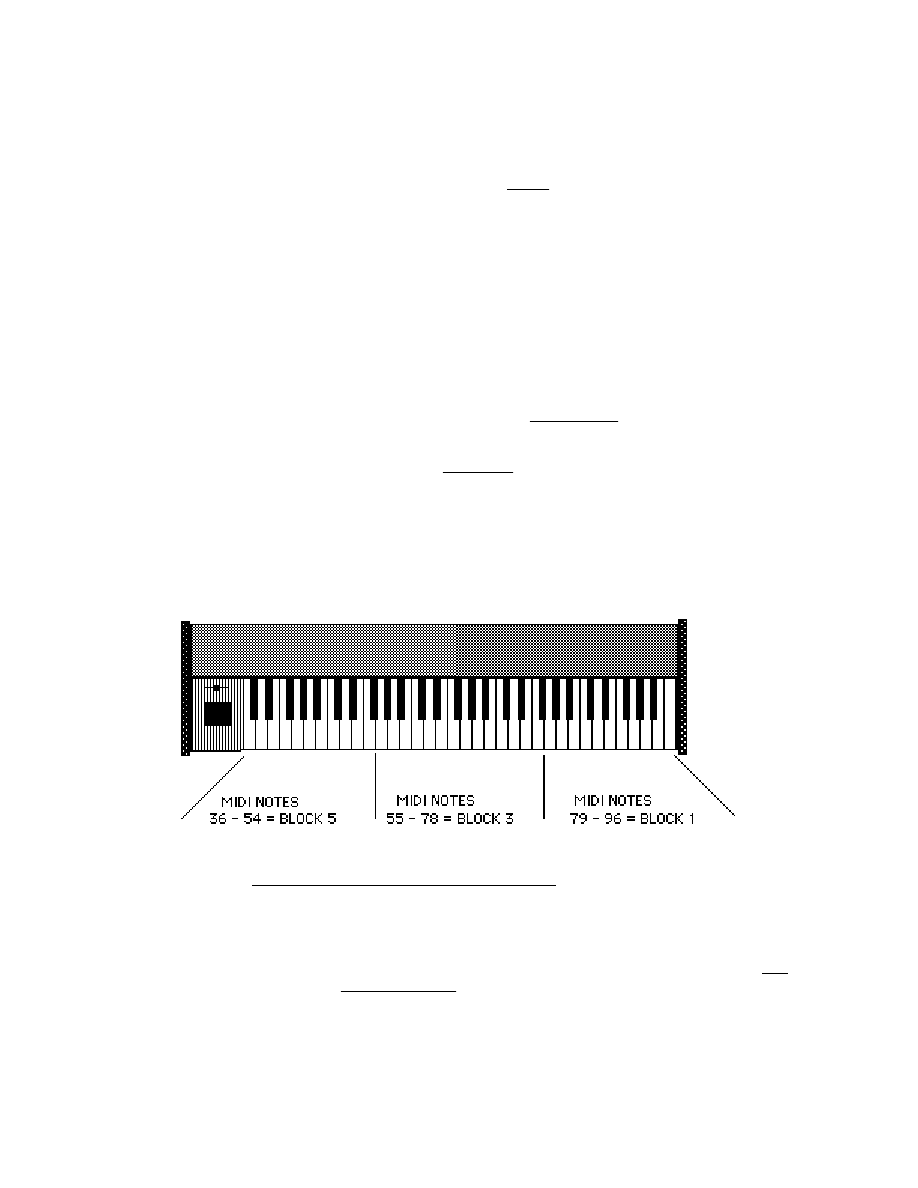
Prommer User's Guide
Appendix 1 - Examples
67
APPENDIX 1 - PART B
USING MIDI Z O N E S
The creative possibilities for using the Prommer with a MIDI keyboard are almost
limitless. An understanding of
zones
is an important key to acheiving these
capabilities. This section will discuss ways of playing notes on a keyboard to
trigger sounds in the Prommer and also change blocks (sounds).
R E Q U I R E M E N T S
To begin with, it will be assumed that you have a keyboard or other controller
capable of transmitting MIDI information including velocity and pressure. Velocity
and pressure are not necessary for playing sounds, but can add dynamic control
of sounds by modulating the VCF and VCA. Velocity also has another use, as will
be discussed later.
Connect the MIDI Output of the keyboard to the MIDI Input of the Prommer.
MIDI ZONE M O D E
With the MIDI Mode on the Prommer to MIDI ZONE MODE, playing a note on the
keyboard will play the sound in the
current
block
at a pitch relative to the note
played based on the current sample rate, transpose and fine tune settings of the
block.
By carefully setting the
zone limits
for each block, you can select a different block
when a note is played that falls outside the zone limits for the current block.
For example, suppose you have three sounds in the Prommer in blocks 1, 3 and
5 and you want to play each of these sounds in a different range depending on
what part of the keyboard you play (see the picture below).
Figure
13
-
MIDI
Zone
Example
To do this, you must set the zone limits for each of the blocks involved, and also
in order to keep the other blocks from playing, you must set the upper
and
lower
limits of
all
unused
blocks
to zero.
For Block 1, set the lower limit to 79 and the upper limit to 127. For Block 3, set
the lower limit to 55 and the upper limit to 78, and for Block 5, set the lower limit to
0 and the upper limit to 54.
Now, select Block 1 and press middle C on the keyboard (MIDI note 60). Notice
that the block number on the display changes to 3 and you hear Block 3 play.

Prommer User's Guide
Appendix 1 - Examples
68
Press keys in other parts of the keyboard and see what happens - notes on the
lower part of the keyboard play Block 5, notes in the middle play Block 3, and
higher notes play Block 1.
Here is what was actually happening when you first pressed middle C: The
current block was Block 1, and the note played (60) was outside of the zone limits
for the block (79-127). Since the note didn't fit within the limits for Block 1, the
limits for the next block, Block 2, were checked against note number 60. Block 2
had both limits set to zero, so again, the note didn't fit within the limits of the
block, and the next block was checked. Block 3 had its limits set to 55 and 78 and
since 60
does
fit within this range, Block 3 became the current block and was
played. This checking process happens every time a new MIDI note is played.
Three blocks were used just as an example here, but if you like, you can control
as many as sixteen blocks from the keyboard, each in its own zone.
SIMULATING A MIDI DRUM MACHINE
Here is one example of using several drum sounds in the Prommer to simulate a
MIDI drum machine. A typical MIDI controlled drum machine uses MIDI notes in a
specific range to play its drums, with each MIDI note in that range assigned to a
different sound. Let's assume that the Prommer has 12 different sounds in
blocks 1 through 12 that you want to play from the range of MIDI notes 36 through
47. Start by setting the zone limits for each of the blocks to its respective MIDI
note - both upper and lower limits should be the same.
Next set both zone limits for unused blocks 13 through 16 to zero, and finally, set
the Key Pitch Enable for all blocks OFF, so all drum sounds will play at their
normal pitches.
Now, playing any key below MIDI note 36 or above 47 will have no effect, and
every key between 36 and 47 will play a different block.
OVERLAPPING Z O N E S
Zones may overlap also. Suppose you have two sounds in the Prommer that you
want to play from the keyboard and the limits for one are set to 37 - 96 and the
other to 36 - 95. With all other block zone limits set to zero, playing a note
anywhere on the keyboard between notes 37 and 95 will play whichever of the
two blocks is currently selected. You can then switch from one block to the other
by playing the highest key (96) or the lowest key (36). Playing note 36 while in
the block with the [37 - 96] limits will switch to the next available block, in this case,
the one with [36 - 95] limits. Playing note 96 then will select the other block.
UNDEFINED Z O N E S
If there are any "holes" in the arrangement of zones (that is a place on the
keyboard that has
no
blocks assigned to it) , and you play a note in this range, the
Prommer will not play any block.

Prommer User's Guide
Appendix 1 - Examples
69
MIDI VELOCITY ZONE M O D E
When the MIDI mode is changed to "VELO. ZONE MODE", all the zone limits that
were set for ranges of the keyboard now will apply to ranges of MIDI Note-On
velocities
. The permissible range of MIDI velocities is the same as for MIDI notes;
0 - 127. If you were to use the setup shown in the picture above, with Velocity
Zone mode selected, blocks 1, 3 or 5 would play depending on how fast you
strike the key on the keyboard. A light touch would play Block number 5, a
moderate stroke would play Block 3, and a fast depression would play Block 1.
You may also divide the ranges of keyboard velocities among up to sixteen
different blocks, but it is difficult to have precise control over velocity, so it is best
to limit the number of blocks controlled by velocity to a maximum of about four.
Also be aware that some types of keyboards are not capable of sending every
possible value of velocity over MIDI.
An example of using Velocity Zone mode might be the case where you have
three samples of the same note from an electric bass guitar. The first sample is a
note that was played softly, the second sample was played a little louder and the
third sample was "popped", or played with great emphasis. Assuming these
samples are in blocks 1, 2 and 3 respectively, you can set the zone limits as
follows: Block #1 limits = 0 - 45, Block #2 limits = 46 - 75, Block #3 limits = 76 -
127, and blocks #4 through #16 limits = 0 - 0.
Now, you can play the bass from the keyboard with dynamic control. A way to
further enhance the control of this sound is to set the MIDI Velocity destination to
VCF, so the velocity also controls the brightness of the sound as well as the
actual sample played.

Prommer User's Guide
Appendix 1 - Examples
70

Prommer User's Guide
Appendix 2
EPROM Cross Reference
71
Oberheim Prommer
EPROM Cross Reference

Prommer User's Guide
Appendix 2
EPROM Cross Reference
72
EPROM COMPATIBILITY
2K EPROMs ( 2 7 1 6 )
Programming of 2716 types is not supported by the Prommer, however, 2716s
may be loaded
into memory by setting the Prommer for a 2732 or 2732A PROM
type. Select a 2k length block and use the LOAD DATA or LOAD LINEAR
function.
4K EPROMS ( 2 7 3 2 )
4K
EPROMs
are
used in
the
:
Oberheim DMX
Linn Drum
S.C.I. Drumtraks
8K EPROMS ( 2 7 6 4 )
8K
EPROMs
are
used in
:
Oberheim DMX
Oberheim DX
Oberheim Stretch
Linn 9000
S.C.I Drumtraks
Simmons SDS-1
(Linear format data)
Simmons SDS-9 (Linear format data)
16K EPROMS ( 2 7 1 2 8 )
16K
EPROMs
are
used in
:
Simmons SDS-1 (Linear format data)
Simmons SDS-9 (Linear format data)
32K EPROMS ( 2 7 2 5 6 )
32K
EPROMs
are
used in
:
Oberheim DX cymbal (serial #H45001 and later)
Oberheim Stretch cymbal
EPROM PROGRAMMING INFORMATION
EPROM type
Capacity
Program Voltage
Algorithm
2732
4k
25
Slow
2732A
4k
21
Slow
2764
8k
21
Fast
2764A
8k
12.5
Fast
27128
16k
21
Fast
27128A
16k
12.5
Fast
27256
32k
12.5
Fast
27256D
32k
21
Fast
27512
64k
12.5
Fast
Am9864
8k
5
Fast
2864A
8k
5
Slow
4k PROMS
Manufacturer
Part #
Type
Select PROM type

Prommer User's Guide
Appendix 2
EPROM Cross Reference
73
AMD
AM2732
*
EPROM
2732
AM2732A
*
EPROM
2732A
Fujitsu
MBM2732A
*
EPROM
2732A
MBM27C32A
EPROM
2732A
MBM2732
*
EPROM
2732
Hitachi
HN27C32
EPROM
2732
HN27C32A EPROM
2732A
HN462732
*
EPROM
2732
HN482732A
*
EPROM
2732A
Intel
2732
EPROM
2732
2732A
*
EPROM
2732A
P2732A
PROM
2732A
Mitsubishi
M5L2732K
EPROM
2732
M5L2732A
EPROM
2732A
National
NMC2732
EPROM
2732
NMC27C32
EPROM
2732
NEC
D2732D
*
EPROM
2732
D2732A
*
EPROM
2732A
SGS
M2732A
*
EPROM
2732A
Texas Inst.
TMS 2732JL
*
EPROM
2732
TMS 2732A
EPROM
2732A
Toshiba
TMM2732D
*
EPROM
2732
TMM2732A
EPROM
2732A
* These types of PROMs have been tested at Oberheim and are known to work
with the Prommer.

Prommer User's Guide
Appendix 2
EPROM Cross Reference
74
8K PROMS
Manufacturer
Part #
Type
Select PROM type
AMD
AM2764
EPROM
2764
AM2764A
EPROM
2764A
AM2864BDC
*
EEPROM
AM9864
AM9864DC
* EEPROM
AM9864
Fujitsu
MBM2764
*
EPROM
2764
MBM27C64
EPROM
2764
Hitachi
HN27C64G
EPROM
2764
HN482764G
*
EPROM
2764
HN482764P
PROM
2764
Intel
2764
EPROM
2764
2764A
EPROM
2764A
P2764
PROM
2764
P2764A
PROM
2764A
Mitsubishi
M5L2764K
EPROM
2764
NEC
D2764
EPROM
2764
SEEQ
DQ5133
*
EPROM
2764
DQ5133H
EPROM
2764
SGS
2764
EPROM
2764
S-MOS
SPM2864C
*
EEPROM
2864C
Texas Inst.
TMS 2764
*
EPROM
2764
Toshiba
TMM2764D
EPROM
2764
* These types of PROMs have been tested at Oberheim and are known to work
with the Prommer.

Prommer User's Guide
Appendix 2
EPROM Cross Reference
75
16K PROMS
Manufacturer
Part #
Type
Select PROM type
AMD
AM27128
EPROM
27128
AM27128A
EPROM
27128A
Fujitsu
MBM27128
*
EPROM
27128
Hitachi
HN27C128
EPROM
27128
HN4827128
EPROM
27128
Intel
27128
EPROM
27128
D27128A
*
EPROM
27128A
Mitsubishi
M5L 27128K
*
EPROM
27128
NEC
D27128
EPROM
27128
SEEQ
5143
EPROM
27128
S-MOS
SPM 27128H
EPROM
27128
SPM 27128C
PROM
27128
Texas Inst.
TMS 27128
EPROM
27128
Toshiba
TMM 27128D
EPROM
27128
TMM 24128P
PROM
27128
* These types of PROMs have been tested at Oberheim and are known to work
with the Prommer.

Prommer User's Guide
Appendix 2
EPROM Cross Reference
76
32K PROMS
Manufacturer
Part #
Type
Select PROM type
AMD
AM27256DC
*
EPROM
27256
Fujitsu
MBM27256
EPROM
27256
MBM27C256
EPROM
27256
General Inst.
27256
EPROM
27256
Hitachi
HN27C256G
EPROM
27256
HN27256G
*
EPROM
27256
HN4827256
EPROM
27256
Intel
D27256
*
EPROM
27256
Mitsubishi
M5L27256
*
EPROM
27256
NEC
D27256
EPROM
27256
D27C256D
*
EPROM
27256D
Oki
27256
EPROM
27256
Toshiba
TMM27256D
*
EPROM
27256D
TMM24256P
PROM
27256D
64K PROMS
Manufacturer
Part #
Type
Select PROM type
AMD
AM27512
*
EPROM
27512
Intel
27512
EPROM
27512
* These types of PROMs have been tested at Oberheim and are known to work
with the Prommer.

Prommer User's Guide
Appendix 3
MIDI Specification
77
Prommer MIDI Specification

Prommer User's Guide
Appendix 3
MIDI Specification
78
PROMMER MIDI IMPLEMENTATION
TRANSMITTED DATA - CHANNEL VOICE MESSAGES
-None-
RECEIVED DATA - CHANNEL VOICE MESSAGES
Status byte
Data bytes
(See notes 1-7)
1000nnnn
0kkkkkkk
Note Off event
0xxxxxxx
Note Off velocity
-Ignored-
1001nnnn
0kkkkkkk
Note On Event
0vvvvvvv
Note On velocity
(vvvvvvv = 0 : Note Off)
1010nnnn
0kkkkkkk
Polyphonic Key Pressure
0vvvvvvv
Pressure value
1011nnnn
0ccccccc
Control change (see Channel Mode msgs.
below)
0xxxxxxx
Control value (ignored)
1100nnnn
0xxxpppp
Program Change
pppp = Block number - 1
1101nnnn
0vvvvvvv
Channel Pressure
vvvvvvv = Pressure value
1110nnnn
0vvvvvvv
Pitch Bend Change LSB
0vvvvvvv
Pitch Bend Change MSB
RECOGNIZED RECEIVE DATA - CHANNEL MODE MESSAGES
1011nnnn
01111011
All Notes Off command
00000000
1011nnnn
01111100
OMNI mode off - Basic channel reverts to last
se
00000000
(All Notes Off)
1011nnnn
01111101
OMNI mode on
00000000
(All notes off)

Prommer User's Guide
Appendix 3
MIDI Specification
79
SYSTEM EXCLUSIVE MESSAGES
PROMMER SYSTEM EXCLUSIVE
SOUND DUMP REQUEST FORMAT (Received)
MIDI Data:
Description:
11110000
System exclusive status byte
00010000
Oberheim ID number
00000101
Prommer ID number
00000000
Command byte 1 : block dump request
0000pppp
Command byte 2 : requested block number - 1
11110111
EOX (End system exclusive data)
PROMMER SOUND DUMP FORMAT (transmitted and received)
11110000
System exclusive status byte
00010000
Oberheim ID number
00000101
Prommer ID number
00000001
Single block sound transfer code
0000pppp
Transmitted block number - 1 (0 - 15)
--------------------------------------------------------------
Note:
Data bytes are sent as four bit nybbles, most significant
nybble sent first (MSN also identified by bit 6 = 1).
--------------------------------------------------------------
(Block Parameters)
0100dddd , 0000dddd
Start address MSB
0100dddd , 0000dddd
Start address LSB
0100dddd , 0000dddd
Block length MSB
0100dddd , 0000dddd
Block length LSB
0100dddd , 0000dddd
Loop start point address offset MSB
0100dddd , 0000dddd
Loop start point address offset LSB
0100dddd , 0000dddd
Loop end point address offset MSB
0100dddd , 0000dddd
Loop end point address offset LSB
0100dddd , 0000dddd
Zone upper limit
0100dddd , 0000dddd
Zone lower limit
0100dddd , 0000dddd
Miscellaneous status:
Bit 7 = Data protected (1) / unprotected (0)
Bit 6 = Pre-emphasis on (1) / off (0)
Bit 5-2 = undefined
Bit 1,0 =
00 sample rate 32kHz
01 sample rate 24kHz
10 sample rate 16kHz
11 sample rate 12kHz
0100dddd , 0000dddd
Playback mode

Prommer User's Guide
Appendix 3
MIDI Specification
80
Bit 7 =
Gated play mode
Bit 6 =
Loop play mode
Bit 5 =
MIDI pitch disable
Bit 4 - 0 =
undefined
0100dddd , 0000dddd
Playback pitch transpose amount
Range = +/- 48 semitones
0100dddd , 0000dddd
Playback pitch fine tune value
Range = -127 to +127
0100dddd , 0000dddd
Playback filter frequency control
0 = Tracking filter
1 - 255 = fixed frequency
0100dddd , 0000dddd
(Future expansion)
0100dddd , 0000dddd
(Future expansion)
0100dddd , 0000dddd
(Future expansion)
0100dddd , 0000dddd
(Future expansion)
0100dddd , 0000dddd
(Future expansion)
(Sound data)
0100dddd , 0000dddd
Sound data starts here
…
…
0100dddd , 0000dddd
Last byte of sound data
11110111
End system exclusive status byte
PROMMER GLOBAL PARAMETER DUMP (Transmitted and received)
The global parameter dump is transmitted automatically after a "System
Exclusive Dump ALL" command.
11110000
System exclusive status byte
00010000
Oberheim ID number
00000101
Prommer ID number
00000011
Parameter Dump code
0100xxxx, 0000xxdd
MIDI mode: 0= keyboard zone,
1=Block/Channel mode, 2=velocity zone
010000dd, 0000dddd
Bend Range [0
≤
d
≤
36]
0100xxxx, 0000xxxd
Program Change Enable: 1=Enabled
0100mxxx , 0000dddd
MIDI Channel (d): 0-15, OMNI mode (m): 1=on
0100xxxx , 0000xxdd
MIDI Velocity destination:0=off, 1=VCA,
2=VCF
0100xxxx , 0000xxdd
MIDI Pressure destination:0=off, 1=VCA,
2=VCF
0100xxxx , 0000xxxd
Idle Bypass Mode: 0=off, 1=on
0100pxxx, 0000xxxd
Ext. trigger enable(d): 1=enabled,
0=disabled
Ext. trigger polarity (p): 1=positive,
0=negative
0100dddd , 0000dddd
Ext. trigger delay MSB
0100dddd , 0000dddd
Ext. trigger delay LSB
11110111
EOX (End system exclusive data)

Prommer User's Guide
Appendix 3
MIDI Specification
81
UNIVERSAL SAMPLE DUMP SYSTEM MESSAGES
DUMP REQUEST: (transmitted and received)
11110000 F0H
System exclusive status byte
01111110 7EH
Universal ID number
0ddddddd - -
Channel number - currently set to Basic channel
on
transmission and ignored on reception.
00000000 03H
Dump Request command byte
0ddddddd - -
Sample Number (LSB) (Block number)
0ddddddd - -
Sample Number (MSB) (zero transmitted,
ignored on
reception)
11110111 F7H
EOX
ACKNOWLEDGE (ACK): (transmitted and received)
Acknowledge is used for handshaking in a closed loop system to signal
acceptance of the header or a packet of information.
11110000 F0H
System exclusive status byte
01111110 7EH
Universal ID number
0ddddddd - -
Channel number
01111111 7FH
ACK command byte
0ddddddd - -
Packet number - Packet number that is being
acknowle
11110111 F7H
EOX
NOT ACKNOWLEDGED (NAK): (transmitted and received)
NAK is used to signal an that an error in reception has occured and that
the indicated packet should be retransmitted.
11110000 F0H
System exclusive status byte
01111110 7EH
Universal ID number
0ddddddd - -
Channel number
01111110 7EH
NAK command byte
0ddddddd - -
Packet number
11110111 F7H
EOX
CANCEL (CAN): (transmitted and received)
Cancels a transmission in progress.
11110000 F0H
System exclusive status byte
01111110 7EH
Universal ID number
0ddddddd - -
Channel number
01111101 7DH
Cancel command byte
0ddddddd - -
Packet number
11110111 F7H
EOX

Prommer User's Guide
Appendix 3
MIDI Specification
82
WAIT: (Received)
Causes the Prommer to suspend transmission until an ACK is received.
11110000 F0H
System exclusive status byte
01111110 7EH
Universal ID number
0ddddddd - -
Channel number
01111100 7CH
Wait command byte
0ddddddd - -
Packet number
11110111 F7H
EOX
SAMPLE DUMP HEADER: (transmitted and received)
Precedes an actual sample dump.
11110000 F0H
System exclusive status byte
01111110 7EH
Universal ID number
0ddddddd - -
Channel number - Currently set to Basic Channel
on
transmission, ignored on reception.
00000001 01H
Sample Dump Header command byte
0ddddddd - -
Sample Number (LSB)
0ddddddd - -
Sample Number (MSB)
000ddddd - -
Sample Format (Number of significant bits; 8 -
28)
0ddddddd - -
Sample period in nanoseconds (LSB)
0ddddddd - -
sample period
0ddddddd - -
sample period (MSB)
0ddddddd - -
Sample length in words (LSB)
0ddddddd - -
sample length
0ddddddd
sample length (MSB)
0ddddddd - -
Sustain Loop Start Point word number (LSB)
0ddddddd - -
sustain loop start point
0ddddddd - -
sustain loop start point (MSB)
0ddddddd - -
Sustain Loop End Point word number (LSB)
0ddddddd - -
sustain loop end point
0ddddddd - -
sustain loop end point (MSB)
0000000d 0 or 1
Loop Type (0= forward only, 1=
backward/forward)
11110111 F7H
EOX

Prommer User's Guide
Appendix 3
MIDI Specification
83
DATA PACKET: (transmitted and received)
As many packets as are necessary to send the entire sample are
transmitted. Packet numbers start at zero and increment by one. After
packet numbers reach 7FH, they start again at zero. The checksum is the
exclusive-OR of all bytes in the packet with the exception of the F0H
sytem exclusive status byte, the EOX status byte and the checksum
itself. Each packet contains exactly 120 data bytes - any unused bytes in
the last packet are filled with zeros. Each word of data is transmitted in
two's complement linear format - left justified in 2, 3, or 4 bytes - 7 bits per
byte. The number of bytes per word depends on the Sample Format
described in the Sample Header.
11110000 F0H
System exclusive status byte
01111110 7EH
Universal ID number
0ddddddd - -
Channel number
00000010 02H
Packet command byte
0ddddddd - -
Running packet count (current packet number)
0ddddddd (120 data bytes)
0ddddddd - -
Checksum of previous 124 bytes
11110111 F7H
EOX
PROMMER REMOTE KEY SYSTEM EXCLUSIVE FORMAT (received)
11110000 System exclusive status byte
00010000 Oberheim ID number
00000101 Prommer ID number
00000010 Command byte : Key stroke(s) follow
0ddddddd 1-15 Data bytes : Key codes (see note 8)
. . . .
Allow time for Prommer to empty key queue
0ddddddd
before sending more key code data bytes.
11110111 F7H
EOX (End system exclusive data)
Note 1: nnnn = Basic Channel -1 (0000 = Channel 1, 0001 = Channel 2,
etc.)
Note 2: kkkkkkk = Note number
Note 3: xxxx = Don't care
Note 4: ccccccc = Controller number
Note 5: vvvvvvv = Value
Note 6: dddd = Data
Note 7: pppp = Program or block number -1

Prommer User's Guide
Appendix 3
MIDI Specification
84
Note 8:
Table of key codes
00H
0
01H
1
02H
2
03H
3
04H
4
05H
5
06H
6
07H
7
08H
8
09H
9
0AH
#
0BH
+/-
0CH
Left Arrow [<]
0DH
CLEAR
0EH
Right Arrow [>]
0FH
PLAY
10H
External Trigger display
11H
Play Mode display
12H
Transpose display
13H
Sample Rate display
14H
Select Block display
15H
EXECUTE
16H
PARAMETERS
17H
RECORD
18H
Stretch display
19H
Mix Blocks display
1AH
Envelope display
1BH
Reverse display
1CH
Copy Block display
1DH
MIDI Mode display
1EH
MIDI Bend Range display
1FH
STOP
20H
Run Program display
21H
Load Data display
22H
Program PROM display
23H
Verify Erasure display
24H
Select PROM display
25H
MIDI Channel display
26H
MIDI Block Dump display
27H
Receive MIDI display
28H
Null
29H
Compare Data display
2AH
PROM Offset display
2BH
Program Linear display
2CH
Transmit Data display
2DH
Filter Frequency display
2EH
Erase Block display
2FH
Erase All display
30H
Examine RAM display
31H
Program Setup display
32H
MIDI Velocity display
33H
Idle Bypass display
34H
Emphasis display
35H
Loop Start display
36H
Loop End display
37H
Ring Modulation display
38H
Mix Ratio display
39H
Swap Blocks display
3AH
Bit Manipulation display
3BH
Record Trigger
Threshold
3CH
Envelope Decay Rate
3DH
Envelope Decay Start
Point
3EH
Data Display Mode
3FH
Memory Protect display
40H
MIDI Program Change
41H
Display Sample Time
42H
Fine Tune display
43H
MIDI Echo display
44H
Block Address display
45H
Block Length display
46H
Zone Lower Limit display
47H
Zone Upper Limit display
48H
Load Setup display
49H
External Trigger Holdoff
4AH
MIDI Pressure display
4BH
Load Linear Data display
4CH
Universal MIDI Dump
4DH
Squash Block display
4EH
Block Address whole num.
4FH
Block Length whole
num.
50H
MIDI Pitch enable display
51H
MIDI Dump All Blocks
disp.
52H
Request Universal Dump
7FH
Immediate EXECUTE (for RUN PROGRAM)

Prommer User's Guide
Appendix 4
Warranty
85
IF YOU HAVE A PROBLEM
W A R R A N T Y
The staff at E.C.C. / Oberheim wish to thank you for purchasing an Oberheim
product and hope that you will remain a long-time Oberheim player. We are
confident that your instrument will provide you with years of excellent service as
each unit is thoroughly tested and inspected before it leaves the factory. The
Owner's Manual was written to be logical and comprehensive so that you will be
able to get the most out of your Oberheim.
Although we have taken great care in manufacturing your Oberheim instrument
and preparing thorough documentation in the manual, products at this level of
technology may require servicing. The following Warranty Policy outlines your
rights and responsibilities, and also lists several limitations of coverage and
important exclusions. We strongly recommend that you read the following policy
statements carefully and refer to the procedure at the end in obtaining service for
your Oberheim product should it ever be needed.
OBERHEIM LIMITED CUSTOMER WARRANTY
(Non-Transferable)
Oberheim, a Division of E.C.C. Development Corporation, warrants its products,
when purchased in the United States of America from an Authorized Oberheim
Dealer, to be free from defects in materials or workmanship for a period of 12
months from the date of purchase. Warranty service is effective and available to
the original purchaser ONLY, and only upon completion and return of the
Oberheim Warranty Registration card within 14 days of the date of purchase.
Warranty coverage is valid for Factory-Authorized updates to Oberheim products
when their installation is performed by an ECC / Oberheim Authorized Service
Center and a properly completed Warranty Certificate is returned to the factory
within 14 days of installation.
To obtain service under this Warranty, the product must, upon discovery of the
defect, be properly packed and shipped to the nearest Oberheim Authorized
Service Center. The party requesting Warranty service must provide proof of
original ownership and date of purchase of the product, or date of installation of
the update, by supplying to the Oberheim Authorized Service Center either the
Warranty Registration Sticker applied to the unit itself, or the sales receipt /
installation receipt. In the event that both have been lost or misplaced, the
Service Center shall, at the Service Center's or owner's expense, contact
Oberheim to verify the Warranty status of the product.
If the Warranty has been verified, Oberheim will, without charge for parts or labor,
either repair or replace the defective part(s). If the Warranty cannot be verified, the
entire cost of the repair in parts and labor is the responsibility of the product's
owner.
PRICES AND SPECIFICATIONS ARE SUBJECT TO CHANGE WITHOUT NOTICE
WHAT IS COVERED

Prommer User's Guide
Appendix 4
Warranty
86
ECC / Oberheim warrants that it will make all necessary adjustments, repairs or
replacements at no cost to the original owner within the first 12 months from the
purchase date if:
1. The product fails to perform its specified functions due to failure of one or more
of its components.
2. The product fails to perform its specified functions due to defects in
workmanship.
3. The product is maintained and operated by the owner in strict accordance with
the written instuctions for proper maintenance and use as specified in the
Owner's Manual.
___________________________________________________________________
WHAT IS NOT C O V E R E D
Before purchasing and using, the owner shall determine the suitability of the
product for his/her intended use, and the owner assumes all risk and liability
whatsoever in connection therewith. Oberheim shall not be liable for any injury,
loss or damage, direct or consequential, arising out of the use or inability to use
the product.
The Warranty provides only the benefits specified and does not cover defects or
repairs needed as a result of acts beyond the control of Oberheim including but
not limited to:
1. Damage caused by abuse, accident or negligence.
Oberheim will not cover under warranty any EPROM, Sound C h i p
or Voice Card damaged or destroyed as a result of the owner's mis-
handling, or the improper removal and installation into t h e
Prommer or DMX, DX or Stretch Digital Drum Machines.
2. Any tampering, alteration or modification of the product's mechanical or
electronic components.
3. Failure to operate the product in strict accordance with the procedures written
in the Owner's Manual.
4. Repairs performed by unauthorized persons.
5. Damage caused by fire, smoke, falling objects, water or liquids etc. or natural
events such as rain, earthquakes, floods, lightning, tornadoes, storms, etc.
6. Damage caused by operation on improper voltages.
IMPORTANT NOTICE: The warranty is VOID if the product is
electronically or mechanically modified, altered or tampered with i n
any way.
Oberheim shall not be liable for costs involved in packing or preparing the product
for shipping with regards to time, labor or materials, shipping and freight costs, or
time and expenses involved in transporting the product to and from an Oberheim
Authorized Service Center, an Oberheim Authorized Dealer or the Oberheim

Prommer User's Guide
Appendix 4
Warranty
87
Factory. If a suitable shipping container is unavailable, a replacement carton may
be purchased from Oberheim.
Oberheim will not cover under Warranty an apparent malfunction that is
determined to be in fact user error, or the owner's inability to use the product.
Oberheim will not cover under Warranty an apparent malfunction that is
inaccurately or inadequately described by the owner to the Service Center at the
time of repair.
THE
DURATION OF ANY OTHER WARRANTIES, W H E T H E R
IMPLIED OR EXPRESS, INCLUDING BUT NOT LIMITED TO T H E
IMPLIED WARRANTY OF MERCHANTABILITY, IS LIMITED TO T H E
DURATION OF THE EXPRESS WARRANTY HEREIN.
Oberheim hereby excludes incidental and consequential damages, including but
not limited to:
1. Loss of time
2. Inconvenience
3. Delay in performance of the Warranty
4. The loss of use of the product
5. Commercial loss
6. Breach of any express or implied warranty, including the Implied Warranty of
Merchantability, applicable to this product.
Oberheim shall not be liable for damage or loss resulting from the negligent or
intentional acts of the shipper or his contract affiliates. The owner of the product
should contact the shipper for proper claims procedures in the event of damage
or loss resulting from shipment.
HOW TO OBTAIN WARRANTY S E R V I C E
If you have reason to believe that your Oberheim product is malfunctioning or
otherwise not operating properly, do the following:
STEP 1:
CONTACT YOUR NEAREST ECC / OBERHEIM SERVICE C E N T E R
Telephone them as soon as the problem is discovered. Be prepared to discuss
the problem as completely and accurately as possible. A current roster of
Authorized Service Centers is included with the Owner's Manual.
The Service Center will let you know when the repair can be scheduled, the
approximate number of days it will take to complete the repair and if the required
parts are in stock or if they need to be ordered.
Take the failed unit to the Service Center along with the sales receipt as the
Service Center will need to verify the Warranty. If you have returned your Warranty
Card, the Warranty Verification Sticker affixed to the bottom panel of your unit is
sufficient to prove warranty status.
The Service Center will then inspect the product and take the necessary steps to
complete the repair.
If the product continues to malfunction or another problem different from the
original problem occurs, contact the service center IMMEDIATELY so that the
problem can be resolved without delay or futher complications.
STEP 2. CONTACT
YOUR
ECC / OBERHEIM D E A L E R

Prommer User's Guide
Appendix 4
Warranty
88
If you feel that your problem has not been resolved, contact the Oberheim Dealer
where the product was purchased. It will be most expedient if you discuss the
matter personally with the salesperson who sold you the instrument. By making
the salesperson aware of your situation, they will be in a better position to assist
you in getting the problem resolved.
STEP 3:
CALL OR WRITE TO THE OBERHEIM F A C T O R Y
If you believe that the problem is still unresolved after you have contacted the
Service Center and Dealer, contact the Oberheim factory. In an attempt to resolve
your problem, we will work with your local Service Center or Dealer to review and
verify the information and facts. Based on these facts, we will advise or consult
with the Service Center or Dealer as appropriate.
Written correspondence should be addressed to:
OBERHEIM
Division of E.C.C. Development Corporation
Customer Services Department
11650 Olympic Boulevard
Los Angeles, CA 90064
Every attempt will be made to respond to your letter as quickly as possible.
If you would prefer to contact the Oberheim factory by telephone, a Service
Representative will be available to assist you. Our telephone hours are from 1:00
PM to 4:00 PM West Coast Time, Monday through Friday only. The Customer
Services Department can be reached at 213-479-4851. Collect calls cannot be
accepted.
When calling the ECC / Oberheim offices:
√
Have your instrument and amplifier turned on and in front of you when you are
on the phone. You should also have your Owner's Manual with you.
√
Tell the receptionist that you are having a problem with your Oberheim product
and ask to speak to a Service Representative.
√
Be prepared to provide the following information:
1. Your name.
2. The model of the product.
3. The product's Serial Number.
4. The name of the Dealer from where it was purchased.
5. The exact date of purchase.
6. A complete description of the problem.
When writing to Oberheim, please also include your full address, telephone
number and the best time to call should it be necessary to call you rather than
answer your letter.

Prommer User's Guide
Specifications
OBERHEIM PROMMER SPECIFICATIONS
Inputs
Microphone input: balanced low impedance XLR connector
Line input: unbalanced high impedance - 1/4 phone jack
Input sensitivity switch selectable:
Line input : +4dB / -10dB
Mic. input : -46dB / -60dB (Ref. 0dB = .775vrms)
External Trigger: AC coupled
Sensitivity: 200mv rms at 1kHz
Trigger response time: 3 milliseconds
MIDI Input: 5 pin DIN socket
Meter
Peak reading LED meter graduated in 3 db steps
Clipping level = +3
Outputs
Unbalanced output - 1/4 inch phone jack
Output level = +3dB ( 4vp-p) for 0db meter reading
MIDI Output: 5 pin DIN socket
Signal to noise ratio
Bypass mode on: 58db
Display
16 Character Alphanumeric Vacuum Fluorescent
Memory capacity
65536 (64K) bytes in16 User definable Blocks
Sampling Rates
12kHz, 16kHz, 24kHz, 32kHz
Maximum Recording time
5.46 seconds
Sampling Format
8 Bit Companding
Power requirements
115vac 18 watts

Prommer User's Guide
EPROM Log
Prommer EPROM Log
EPROM NAME:
EPROM type:
Block size:
Data offset:
Description of sound or data:
Performance data
Sample rate:
Transpose:
Fine tune:
Filter setting:
Emphasis:
Loop mode:
Loop start:
Loop end:
N o t e s :
Programmer's name:
Creation date:
Prommer EPROM Log
EPROM NAME:
EPROM type:
Block size:
Data offset:
Description of sound or data:
Performance data
Sample rate:
Transpose:
Fine tune:
Filter setting:
Emphasis:
Loop mode:
Loop start:
Loop end:
N o t e s :
Programmer's name:
Creation date:
Wyszukiwarka
Podobne podstrony:
Oberheim Prommer Service Manual
Oberheim Prommer Service Manual
Bmw 01 94 Business Mid Radio Owners Manual
Alpine MRD M300 Mono ampl Owners Manual
MPC The Kit Owners Manual
Alpine CDM 7874,7872,7871,CDE 7860 Owners Manual
Bmw 01 94 Business Mid Radio Owners Manual
Pioneer CS 53 Owners Manual
Kenwood CRS 155 Owners Manual
Nec NDT 42 Owners Manual
Yamaha AX 890 Owners Manual
Gibson LP Standard 2010 Owners Manual 1 0
Pioneer BDP 208DBK Owners Manual
Nec N8151 32B Owners Manual
Yamaha AX 10 Owners Manual
Kenwood Basic M 1 D Owners Manual
Cessna 172 owners manual
więcej podobnych podstron