EN
DE
FR
ES
IT
SE
R
ALPINE ELECTRONICS, INC.
Tokyo office: 1-1-8 Nishi Gotanda,
Shinagawa-ku,
Tokyo 141-8501, Japan
Tel.: (03) 3494-1101
ALPINE ELECTRONICS OF AMERICA, INC.
19145 Gramercy Place, Torrance,
California 90501, U.S.A.
Tel.: 1-800-ALPINE-1 (1-800-257-4631)
ALPINE ELECTRONICS OF CANADA, INC.
Suite 203, 7300 Warden Ave. Markham,
Ontario L3R 9Z6, Canada
Tel.: 1-800-ALPINE-1 (1-800-257-4631)
ALPINE ELECTRONICS FRANCE S.A.R.L.
(RCS PONTOISE B 338 101 280)
98, Rue De La Belle Etoile, Z.I. Paris Nord Il
B.P. 50016 F-95945, Roissy, Charles De Gaulle
Cedex, France
Tel.: 01-48 63 89 89
ALPINE ELECTRONICS OF U.K., LTD.
13 Tanners Drive, Blakelands, Milton Keynes
MK14 5BU, U.K.
Tel.: 01908-61 15 56
ALPINE ELECTRONICS DE ESPAÑA, S.A.
Portal De Gamarra 36, Pabellón 32
01013 Vitoria (Alava)-Apdo. 133, Spain
Tel.: 34-45-283588
ALPINE ELECTRONICS OF AUSTRALIA PTY. LTD.
6-8 Fiveways Boulevarde Keysborough,
Victoria 3173, Australia
Tel.: (03) 9769-0000
ALPINE ELECTRONICS GmbH
Kreuzerkamp 7-11 40878 Ratingen, Germany
Tel.: 02102-45 50
ALPINE ITALIA S.p.A.
Via C. Colombo 8, 20090 Trezzano Sul Naviglio
MI, Italy
Tel.: 02-48 47 81
CDM-7874R
CDM-7872R
CDM-7871R
CDE-7860R
Designed by ALPINE Japan
Printed in China (Y)
68P01434K85-O
• OWNER'S MANUAL
Please read before using this equipment.
• BEDIENUNGSANLEITUNG
Lesen Sie diese Bedienungsanleitung bitte vor
Gebrauch des Gerätes.
• MODE D'EMPLOI
Veuillez lire avant d’utiliser cet appareil.
• MANUAL DE OPERACIÓN
Léalo antes de utilizar este equipo.
• ISTRUZIONI PER L’USO
Si prega di leggere prima di utilizzare il
attrezzatura.
• ANVÄNDARHANDLEDNING
Innan du använder utrustningen bör du läsa
igenom denna användarhandledning.
FM/MW/LW/RDS CD Receiver
Meiyi Printing Factory, Dalian, China
No. 28 Chang Qing Street, Xi Gang District, Dalian, China
CHM-S630
• CD changer for CDM-7874R/
CDM-7872R/CDM-7871R
• CD-Wechsler für CDM-7874R/
CDM-7872R/CDM-7871R
• Changeur CD pour CDM-7874R/
CDM-7872R/CDM-7871R
• Cambiador de CD para
CDM-7874R/CDM-7872R/CDM-7871R
• Cambia CD per CDM-7874R/
CDM-7872R/CDM-7871R
• CD-växlare för CDM-7874R/
CDM-7872R/CDM-7871R
CHA-1214
CHA-S634
Alpine CD Changers Give You More!
More musical selections, more versatility, more convenience.
The CHA-S634 is a high-performance 6-disc changer with a new M DAC, CD-R/RW PLAY BACK, MP3 PLAY BACK and CD TEXT.
The CHA-1214 Ai-NET model holds 12 discs, and the CHM-S630 M-Bus model is a super-compact 6-disc changer with a CD-R/RW
PLAY BACK.
NOTE
The CHA-S634 model can be connected to the M-Bus model Head Unit using the optional M-Bus/Ai-NET compatible cable. (KCA-130B)
Von Alpine CD-Wechslern haben Sie mehr!
Mehr Musikauswahl, mehr Vielseitigkeit, mehr Komfort.
Der CHA-S634 ist ein Hochleistungs-Wechsler für 6 CDs mit dem neuen M-DAC, mit CD-R/RW- und MP3-Wiedergabefunktion und
mit CD-TEXT. Der CHA-1214 ist ein Ai-NET-Modell für 12 CDs. Der M-Bus-kompatible CHM-S630 ist ein superkompakter Wechsler
für 6 CDs mit CD-R/RW-Wiedergabefunktion.
HINWEIS
Das Modell CHA-S634 kann mit einem M-Bus-/Ai-NET-kompatiblen Kabel (KCA-130B) an das zusätzlich erhältliche M-Bus-Hauptgerät
angeschlossen werden.
Changeurs de CD Alpine : vous avez le choix!
Plus de sélections musicales, plus de souplesse, plus de confort.
Le modèle CHA-S634 est un changeur 6 disques ultra performant équipé des nouvelles fonctions M DAC, CD-R/RW PLAY BACK,
MP3 PLAY BACK et CD TEXT. Le modèle CHA-1214 Ai-NET contient 12 disques. Le modèle CHM-S630 M-Bus est un changeur 6
disques super compact doté de la fonction CD-R/RW PLAY BACK.
REMARQUE
Le modèle CHA-S634 peut être raccordé à l’appareil principal du modèle M-Bus en option à l’aide du câble compatible
M-Bus/Ai-NET (KCA-130B).
¡Los cambiadores Alpine de CD le ofrecen más!
Más selecciones musicales, más versatilidad y más ventajas.
CHA-S634 es un cambiador de seis discos de alto rendimiento con nuevo M DAC, CD-R/RW PLAY BACK, MP3 PLAY BACK y CD
TEXT. El modelo CHA-1214 Ai-NET alberga 12 discos y el modelo CHM-S630 M-Bus es un cambiador de seis discos de tamaño
reducido con un CD-R/RW PLAY BACK.
NOTA
El modelo CHA-S634 se puede conectar a la unidad principal del modelo opcional M-Bus utilizando el cable compatible M-Bus/Ai-NET. (KCA-130B)
I caricatori CD Alpine danno di più!
Più scelta, più versatilità, più comodità.
Il modello CHA-S634 è un caricatore a 6 dischi ad elevate prestazioni dotato di un nuovo M DAC, CD-R/RW PLAY BACK, MP3 PLAY
BACK e CD TEXT. Il modello CHA-1214 Ai-NET è in grado di contenere 12 dischi, il modello CHM-S630 M-Bus è un caricatore a 6
dischi ultra compatto dotato di un CD-R/RW PLAY BACK.
NOTA
Il modello CHA-S634 può essere collegato all’unità principale modello M-Bus mediante il cavo M-Bus/Ai-NET compatibile (KCA-130B).
Alpines CD-växlare ger mer!
Fler musikval, mer variation, större bekvämlighet.
C
HA-S634 är en växlare för 6 skivor med mycket höga prestanda och en ny M D/A-omvandlare samt uppspelning av CD-R/RW, MP3
och CD TEXT. CHA-1214 Ai-NET rymmer 12 skivor. CHM-S630 M-Bus är en mycket kompakt växlare med kapaciteten 6 skivor med
uppspelning av CD-R/RW PLAY BACK.
OBS!
CHA-S634 kan inte anslutas till M-Bus Huvudenhet (tillval) med en M-Bus/Ai-NET-kompatibel kabel. (KCA-130B)

1
-EN
Contents
Operating Instructions
WARNING
WARNING .................................................. 2
CAUTION ................................................... 2
PRECAUTIONS ......................................... 2
Basic Operations
Detaching the Front Panel .................................. 4
Attaching the Front Panel .................................. 4
Initial System Start-Up ...................................... 4
Turning Power On and Off ................................ 5
Adjusting Volume/Balance
(Between Left and Right)/Fader
(Between Front and Rear) .............................. 5
Turning Loudness On/Off .................................. 5
Audio Mute Function ......................................... 5
Setting the Bass Control .................................... 6
Setting the Treble Control .................................. 6
Radio Operations
Manual Tuning ................................................... 7
Automatic Seek Tuning ..................................... 7
Manual Storing of Station Presets ..................... 8
Automatic Memory of Station Presets ............... 8
Tuning to Preset Stations ................................... 8
RDS Operations
Setting RDS Reception Mode and Receiving
RDS Stations .................................................. 9
Recalling Preset RDS Stations ........................... 9
Receiving RDS Regional (Local) Stations ...... 10
Receiving Traffic Information .......................... 10
PTY (Programme Type) Tuning ...................... 10
Receiving Traffic Information While Playing
CD or Radio .................................................. 11
Priority News ................................................... 11
CD Player Operation
Inserting/Ejecting Disc .................................... 12
Normal Play and Pause .................................... 13
Music Sensor (Skip) ......................................... 13
Fast Forward and Backward ............................ 13
Repeat Play ...................................................... 13
M.I.X. (Random Play) ..................................... 13
Scanning Programmes ..................................... 14
Controlling CD Changer (Optional)
(CDM-7874R/CDM-7872R/CDM-7871R
only) .............................................................. 14
SETUP Operation
Subwoofer On and Off ..................................... 15
Adjusting Source Signal Levels ....................... 15
Changing Audio Level Display Pattern ........... 15
Setting the AUX Mode
(CDM-7874R/CDM-7872R/CDM-7871R
only) .............................................................. 16
Switching the Tuner Mode ............................... 16
Information
In Case of Difficulty ........................................ 17
Specifications ................................................... 19
Installation and Connections
Precautions ....................................................... 20
Installation ....................................................... 21
Connection ....................................................... 22
ENGLISH
2
-EN
WARNING
This symbol means important instructions.
Failure to heed them can result in serious
injury or death.
DO NOT OPERATE ANY FUNCTION THAT TAKES YOUR
ATTENTION AWAY FROM SAFELY DRIVING YOUR
VEHICLE.
Any function that requires your prolonged attention
should only be performed after coming to a complete stop.
Always stop the vehicle in a safe location before
performing these functions. Failure to do so may result in
an accident.
KEEP THE VOLUME AT A LEVEL WHERE YOU CAN
STILL HEAR OUTSIDE NOISE WHILE DRIVING.
Failure to do so may result in an accident.
DO NOT DISASSEMBLE OR ALTER.
Doing so may result in an accident, fire or electric shock.
USE ONLY IN CARS WITH A 12 VOLT NEGATIVE
GROUND.
(Check with your dealer if you are not sure.) Failure to do
so may result in fire, etc.
KEEP SMALL OBJECTS SUCH AS BATTERIES OUT
OF THE REACH OF CHILDREN.
Swallowing them may result in serious injury. If
swallowed, consult a physician immediately.
USE THE CORRECT AMPERE RATING WHEN
REPLACING FUSES.
Failure to do so may result in fire or electric shock.
DO NOT BLOCK VENTS OR RADIATOR PANELS.
Doing so may cause heat to build up inside and may result
in fire.
USE THIS PRODUCT FOR MOBILE 12V APPLICATIONS.
Use for other than its designed application may result in
fire, electric shock or other injury.
DO NOT PLACE HANDS, FINGERS OR FOREIGN
OBJECTS IN INSERTION SLOTS OR GAPS.
Doing so may result in personal injury or damage to the
product.
WARNING
CAUTION
This symbol means important instructions.
Failure to heed them can result in injury or
material property damage.
HALT USE IMMEDIATELY IF A PROBLEM APPEARS.
Failure to do so may cause personal injury or damage to
the product. Return it to your authorized Alpine dealer or
the nearest Alpine Service Centre for repairing.
PRECAUTIONS
Temperature
Be sure the temperature inside the vehicle is between
+60°C (+140°F) and –10°C (+14°F) before turning your
unit on.
Moisture Condensation
You may notice the CD playback sound wavering due to
condensation. If this happens, remove the disc from the
player and wait about an hour for the moisture to
evaporate.
Damaged Disc
Do not attempt to play cracked, warped, or damaged
discs. Playing a bad disc could severely damage the
playback mechanism.
Maintenance
If you have problems, do not attempt to repair the unit
yourself. Return it to your Alpine dealer or the nearest
Alpine Service Station for servicing.
FR
ES
DE
SE
IT
3
-EN
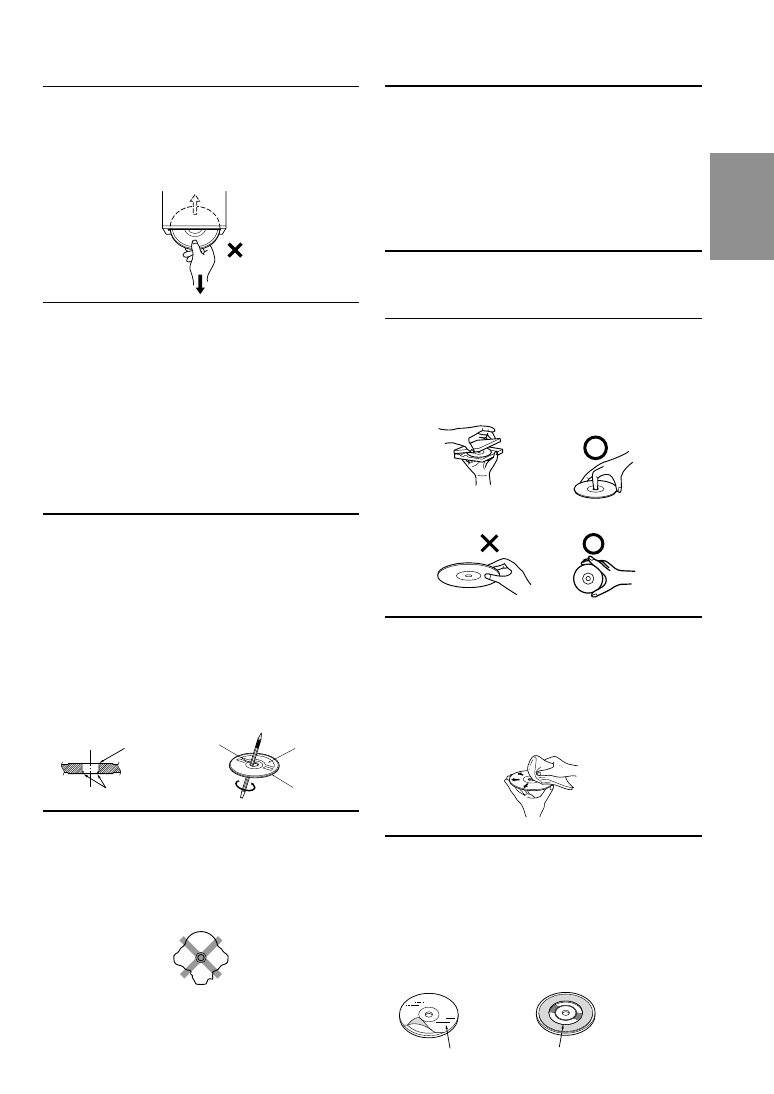
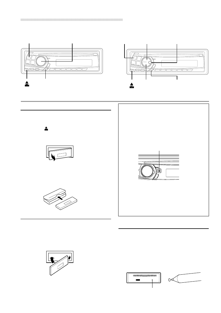
Never Attempt the Following
Do not grip or pull out the disc while it is being pulled
back into the player by the automatic reloading
mechanism.
Do not attempt to insert a disc into the unit when the unit
power is off.
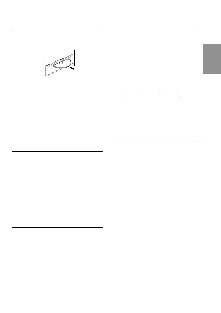
Inserting Discs
Your player accepts only one disc at a time for playback.
Do not attempt to load more than one disc.
Make sure the label side is facing up when you insert the
disc. Your player will automatically eject any disc that is
inserted incorrectly. If the player continues to eject a
correctly inserted disc, push the Reset switch with a
pointed object such as a ballpoint pen.
Playing a disc while driving on a very bumpy road may
result in skips, but this will not scratch the disc or damage
the player.
New Discs
As a protective measure to prevent the CD from jamming,
the CD player will automatically eject discs with irregular
surfaces or inserted incorrectly. When a new disc is
inserted into the player and ejected after initial loading,
using your finger, feel around the inside of the centre hole
and outside edge of the disc. If you feel any small bumps
or irregularities, this could inhibit proper loading of the
disc. To remove the bumps, rub the inside edge of the hole
and outside edge of the disc with a ballpoint pen or other
such instrument, then insert the disc again.
Irregular Shaped Discs
Be sure to use round shape discs only for this unit and
never use any special shape discs.
Use of special shape discs may cause damage to the
mechanism.
Installation Location
Make sure the CDM-7874R/CDM-7872R/CDM-7871R/
CDE-7860R will not be installed in a location subjected
to:
• Direct sun and heat
• High humidity and water
• Excessive dust
• Excessive vibrations
Handling the Detachable Front Panel
• Do not expose to rain or water.
• Do not drop or apply shock.
Correct Handling
Do not drop the disc while handling. Hold the disc by its
edge so that no fingerprints are left on the surface. Do not
affix tape, paper, or gummed labels to the disc. Do not
write on the disc.
Disc Cleaning
Fingerprints, dust, or soil on the surface of the disc could
cause the CD player to skip. For routine cleaning, wipe
the playing surface with a clean, soft cloth from the centre
of the disc to the outer edge. If the surface is heavily
soiled, dampen a clean, soft cloth in a solution of mild
neutral detergent before cleaning the disc.
Disc Accessories
There are various accessories available on the market for
protecting the disc surface and improving sound quality.
However, most of them will influence the thickness and/or
diameter of the disc. Using such accessories can cause the
disc to be out of standard specifications and may create
operational problems. We recommend not using these
accessories on discs played in Alpine CD players.
Centre
Hole
Bumps
Centre
Hole
Transparent Sheet
Disc Stabilizer
C O R R E C T
I N C O R R E C T
C O R R E C T
New
Disc
Outside
(Bumps)
4
-EN
Detaching the Front Panel
1
Press and hold the POWER button for at least 3
seconds to turn off the power.
2
Press the
(Release) button at lower left corner
until the front panel pops out.
3
Grasp the left side of the front panel and pull it out.
NOTES
• The front panel may become hot in normal usage
(especially the connector terminals), this is not a
malfunction.
• To protect the front panel, place it in the supplied
carrying case.
Attaching the Front Panel
1
First, insert the right side of the front panel into
the main unit. Align the groove on the front panel
with the projection on the main unit.
2
Push the left side of the front panel until it locks
firmly into the main unit.
NOTE
Before attaching the front panel, make sure that there is
no dirt or dust on the connector terminals and no
foreign object between the front panel and the main unit.
• Controllable With Remote Control
(CDM-7874R/CDM-7872R/CDM-7871R only)
This unit can be controlled with an optional
Alpine remote control. For details, consult your
Alpine dealer.
Point the optional remote control transmitter at
the remote control sensor.
• Connectable to Remote Control Interface Box
(CDM-7874R/CDM-7872R/CDM-7871R only)
You can operate this unit from the vehicle's
control unit when an Alpine Remote Control
Interface Box (optional) is connected. For
details, contact your Alpine dealer.
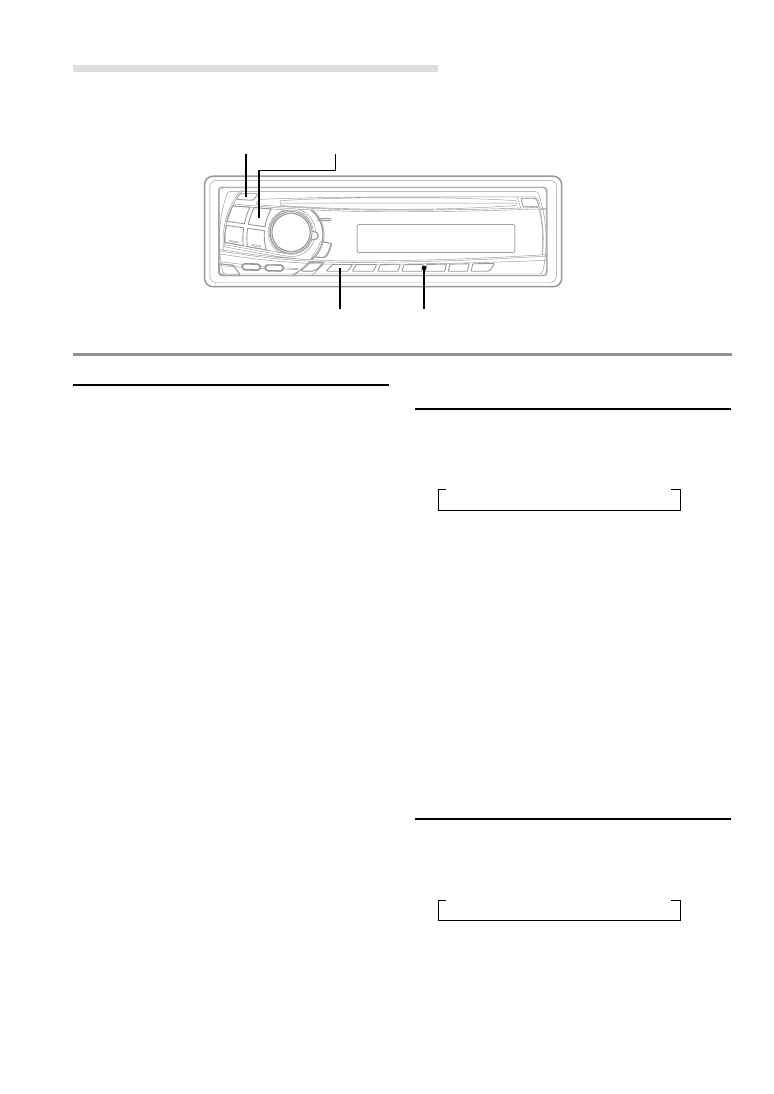
Initial System Start-Up
1
Immediately after installing or applying power to
the unit, it should be initialized. To do this, first,
remove the detachable front panel. Behind the
front panel, to the right of the connector, there is
a small hole. Using a pencil or other pointed
object, press the Reset switch mounted behind
this hole to complete the initialization procedure.
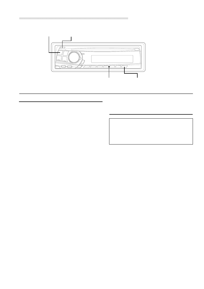
Basic Operations
2
1
1
2
1
Reset switch
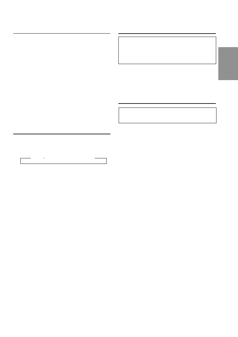
MODE / LOUD (Rotary encoder)
(CDM-7874R only)
POWER
(CDM-7874R)
MODE / LOUD
1
(CDM-7872R)
(CDM-7871R)
(CDE-7860R)
Remote control sensor
MUTE
POWER
MUTE
FR
ES
DE
SE
IT
5
-EN
Turning Power On and Off
1
Press the POWER button to turn on the unit.
NOTE
The unit can be turned on by pressing any other button
except the eject c button.
The volume level gradually increases to the
previous level you were listening to before the
unit was turned off.
Press and hold the POWER button again for at
least 3 seconds.
NOTE
The very first time the power is turned on, the volume
will start from level 12, and the LOUD function will be
on in the tuner mode.
Adjusting Volume/Balance
(Between Left and Right)/Fader
(Between Front and Rear)
1
Press the MODE button repeatedly to choose
the desired mode.
Each press changes the modes as follows:
Volume: 0 ~ 35
Balance: L15 ~ R15
Fader: R15 ~ F15
Subwoofer: 0 ~ +15
NOTES
• If the Rotary encoder (CDM-7874R only) is not
rotated or the
5 or 6 button (CDM-7872R/CDM-
7871R/CDE-7860R only) is not pressed in 5 seconds
after selecting the BALANCE and FADER modes, the
unit automatically sets in the VOLUME mode.
• *When the subwoofer is set to ON, the level of the
subwoofer can be adjusted.
2
Rotate the Rotary encoder (CDM-7874R only)
or press the
5 and 6 buttons (CDM-7872R/CDM-
7871R/CDE-7860R only) until the desired sound
is obtained in each mode.
Turning Loudness On/Off
Loudness introduces a special low- and high-
frequency emphasis at low listening levels. This
compensates for the ear's decreased sensitivity
to bass and treble sound.
1
Press and hold the LOUD button for at least
2 seconds to activate or deactivate the loudness
mode. The display shows "LOUD ON" when the
loudness mode is activated.
Audio Mute Function
Activating this function will instantly lower the
volume level by 20 dB.
1
Press the MUTE button fto activate the MUTE
mode. The audio level will decrease by about 20
dB.
Pressing the MUTE button again will bring the
audio back to its previous level.
→ VOL → SUB-W* → BAL → FAD
6
-EN
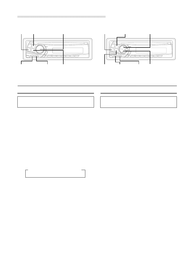
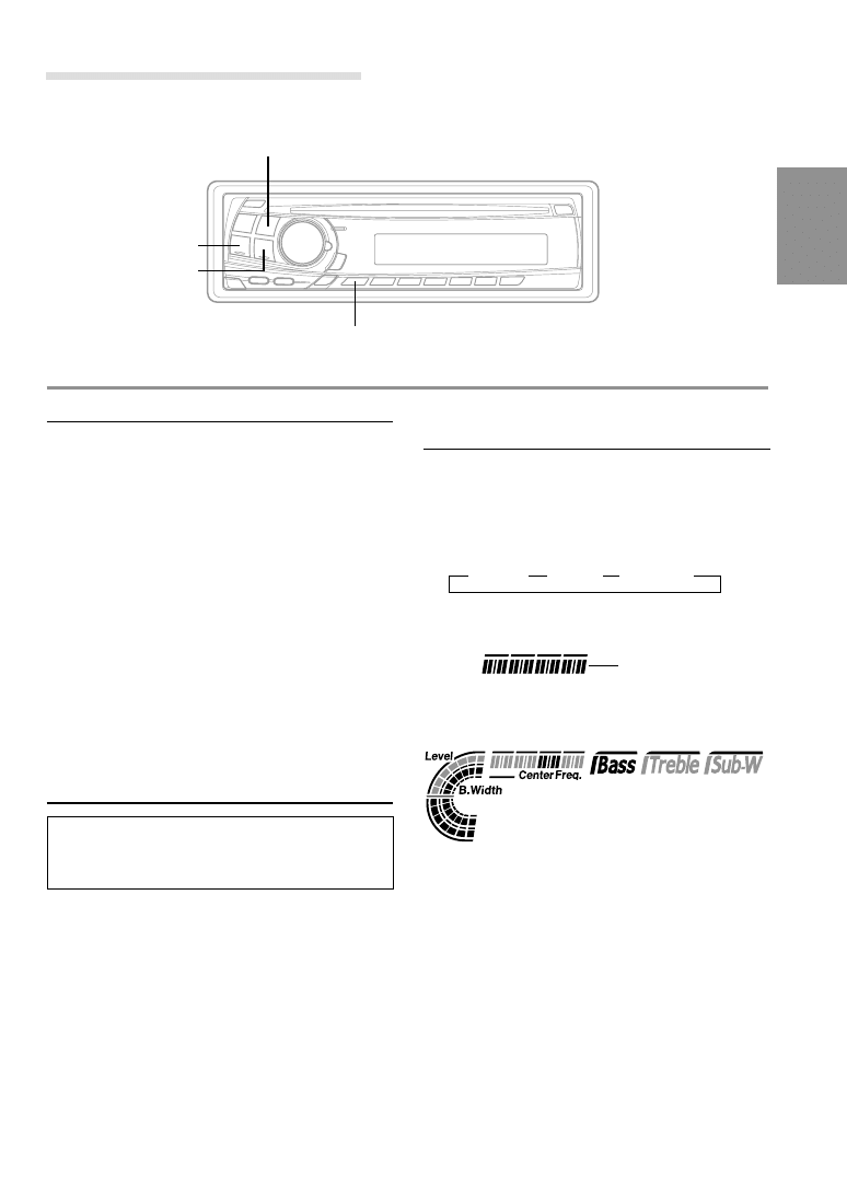
Basic Operation
BAND
f UP
g DN
BASS C.
TREBLE C.
1
2
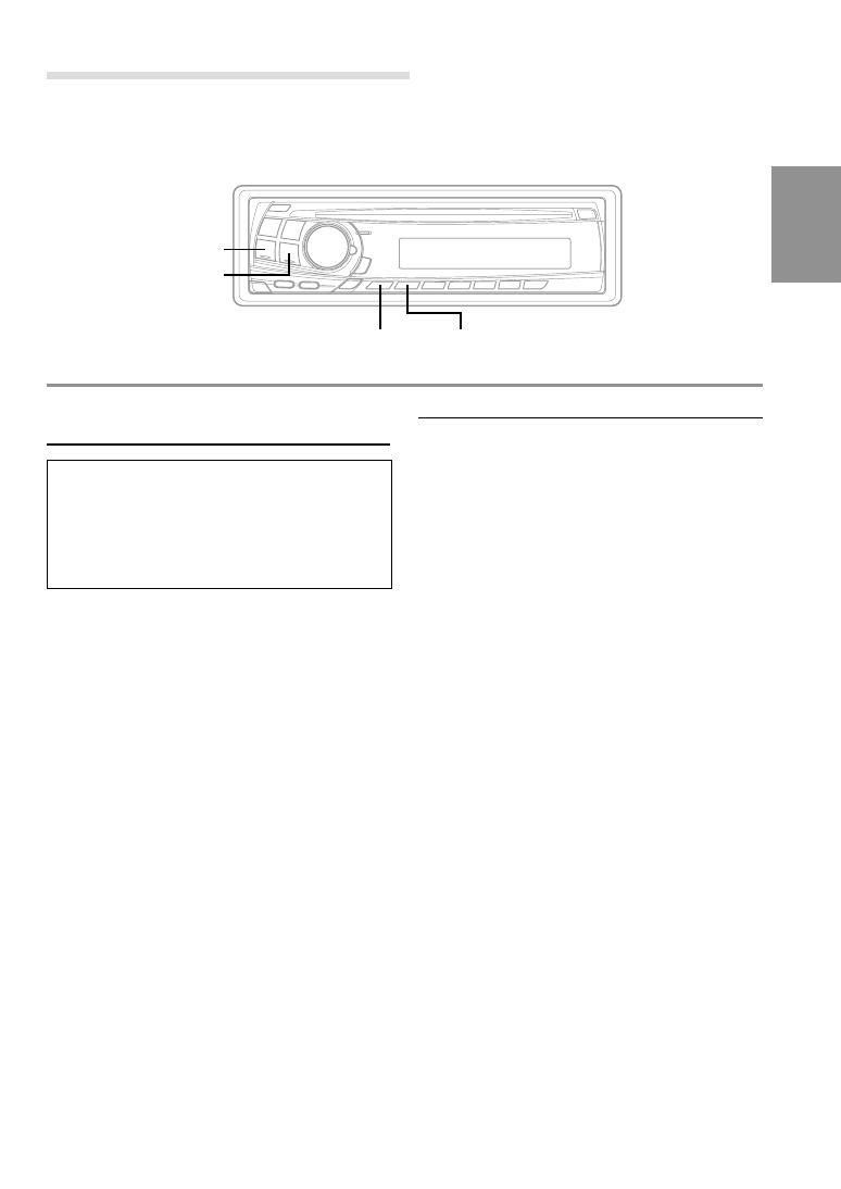
Setting the Bass Control
You can change the Bass Frequency emphasis
to create your own tonal preference.
1
Press the BASS C. button to turn on the Bass
setting mode.
2-1
Setting the Bass frequency:
Press the g DN or f UP button to select
the desired Bass centre frequency.
60Hz
↔ 80Hz ↔ 100Hz ↔ 200Hz
Emphasizes the displayed Bass frequency
ranges.
2-2
Setting the Bass Band Width (Q-Factor):
Press the BAND button to select the desired
Bass Band Width.
Changes the displayed frequency's band width
to narrow or wide.
2-3
Setting the Bass Level:
Rotate the Rotary encoder (CDM-7874R only)
or press the
55555 or 66666 button (CDM-7872R/CDM-
7871R/CDE-7860R only) to select the desired
Bass Level (-7~+7).
You can emphasize or weaken the bass
frequency.
NOTES
• If no buttons are pressed within 5 seconds, the Bass
control setting will be turned off automatically.
• The settings of the Bass Level will be individually
memorized for each source (FM, MW (LW) and CD)
until the setting is changed. Once you set Bass
frequency and Bass Band Width for one of sources
(FM, MW (LW) and CD), this setting becomes
effective for all those sources.
Setting the Treble Control
You can change the Treble Frequency emphasis
to create your own tonal preference.
1
Press the TREBLE C. button to turn on the
Treble setting mode.
2-1
Setting Treble frequency:
Press g DN or f UP button to select the
desired Treble centre frequency.
10kHz
↔ 12.5kHz ↔ 15kHz ↔ 17.5kHz
Emphasizes the displayed Treble frequency
ranges.
2-2
Setting Treble Level:
Rotate the Rotary encoder (CDM-7874R only)
or press the
55555 or 66666 button (CDM-7872R/CDM-
7871R/CDE-7860R only) to select the desired
Treble Level (-7~+7).
You can emphasize the treble frequency.
NOTES
• If no buttons are pressed within 5 seconds, the Treble
control setting will be turned off automatically.
• The settings of the Treble Level will be individually
memorized for each source (FM, MW (LW) and CD)
until the setting is changed. Once you set Treble
frequency for one of sources (FM, MW (LW) and
CD), this setting becomes effective for all those
sources.
→ WIDE1 → WIDE2→ WIDE3 → WIDE4
(Wide)
←
→(Narrow)
...........................
Rotary encoder
(CDM-7874R only)
(CDM-7872R)
(CDM-7871R)
(CDE-7860R)
BAND
f UP
g DN
BASS C.
TREBLE C.
(CDM-7874R)
7
-EN
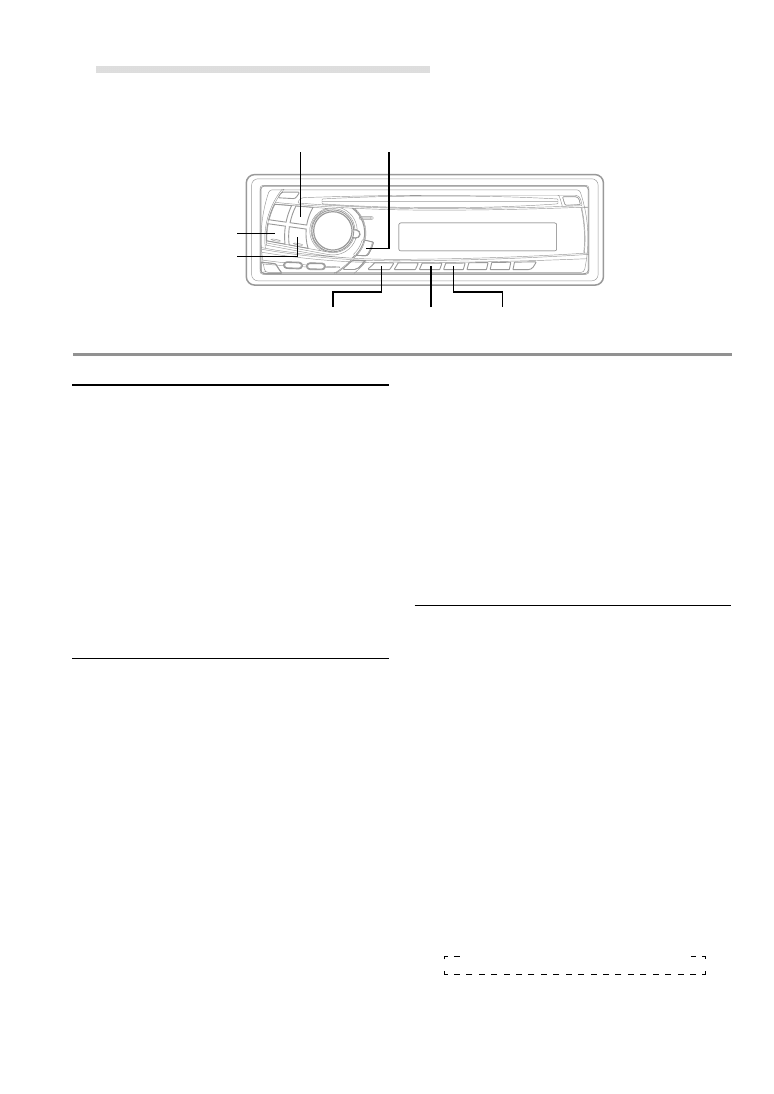
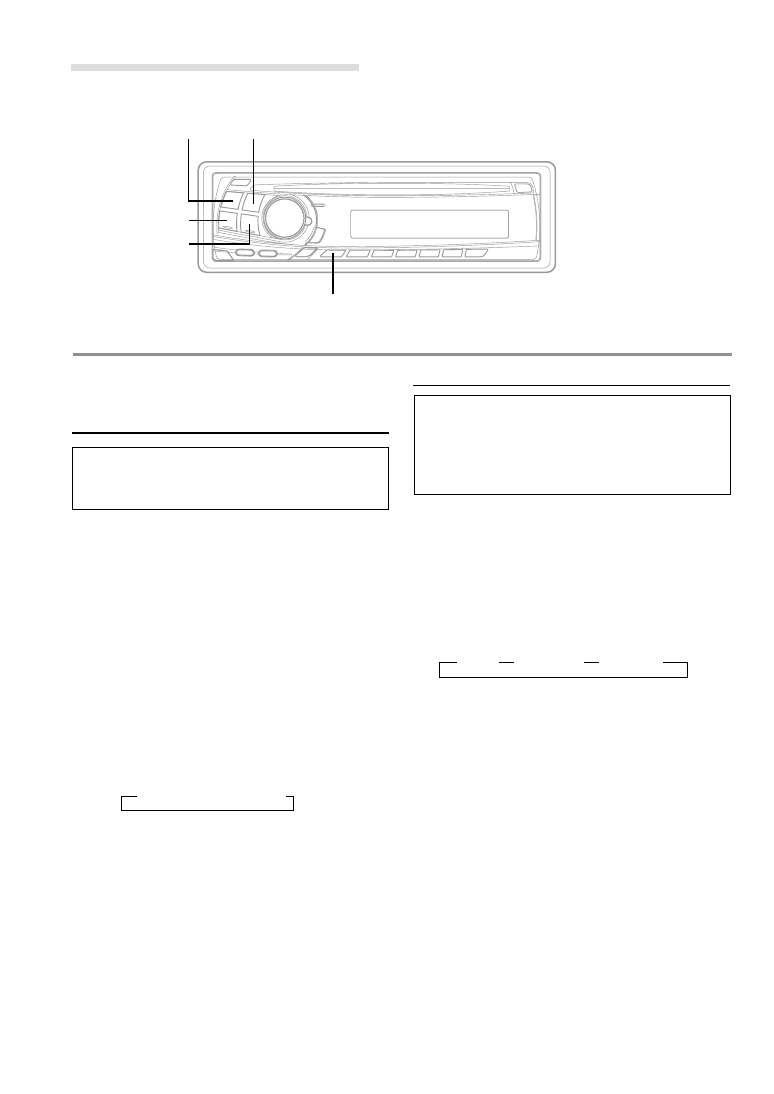
Radio Operations
TUNE
SOURCE
f UP
g DN
BAND
Manual Tuning
1
Press the SOURCE button to select the radio
mode.
2
Press the BAND button repeatedly until the
desired radio band is displayed.
Each press changes the band:
3
Press the TUNE button repeatedly until "DX
SEEK" and "SEEK" disappear from the display.
NOTE
The initial mode is DX SEEK.
4
Press the g DN or f UP button to move
downward or upward one step respectively until
the desired station frequency is displayed.
NOTE
The ST indicator appears on the display when a Stereo
FM station is tuned in.
Automatic Seek Tuning
1
Press the SOURCE button to select the radio
mode.
2
Press the BAND button repeatedly until the
desired radio band is displayed.
Each press changes the band:
3
Press the TUNE button to illuminate the DX and
SEEK indicators in the display.
The SEEK indicator illuminates. With the DX
mode activated, both strong and weak stations
will be tuned in the Auto-Seek operation.
Press again to return to the local mode. The DX
indicator will turn off and the SEEK indicator will
illuminate for a few seconds. Now, only strong
stations will be tuned.
4
Press the g DN or f UP button to
automatically seek a station downward or
upward respectively.
The unit will stop at the next station it finds.
Press the same button again to seek the next
station.
→ F1(FM1) → F2(FM2) → MW → LW
→ F1(FM1) → F2(FM2) → MW → LW
8
-EN
Manual Storing of Station Presets
1
Select the radio band and tune in a desired radio
station you wish to store in the preset memory.
2
Press the F button so that the "FUNC" indicator
light goes out. Press and hold the Preset
buttons (1 through 6) that you want to store the
station on for at least 2 seconds.
The selected station is stored. The display shows
the band, preset No. with a triangle (
9) and
station frequency memorized.
3
Repeat the procedure to store up to 5 other
stations onto the same band.
To use this procedure for other bands, simply
select the band desired and repeat the
procedure.
A total of 24 stations can be stored in the preset
memory (6 stations for each band; FM1, FM2,
MW and LW).
NOTE
If you store a station in a preset memory which already
has a station, the current station will be cleared and
replaced with the new station.
Automatic Memory of Station
Presets
1
Press the BAND button repeatedly until the
desired radio band is displayed.
Each press changes the band:
2
Press and hold the A.ME button for at least 2
seconds.
The tuner will automatically seek and store 6
strong stations in the selected band in order of
signal strength.
The frequency on the display continues to
change while the automatic memory is in
progress.
When the automatic memory has been
completed, the tuner goes to the station stored
in the preset location No. 1.
NOTE
If no stations are stored, the tuner will return to the
original station you were listening to before the auto
memory procedure began.
Tuning to Preset Stations
1
Press the BAND button repeatedly until the
desired band is displayed.
Each press changes the band:
2
Press the F button so that the "FUNC" indicator
light goes out. Then press the station preset
button that has your desired radio station in
memory.
The display shows the band, preset number with
a triangle and frequency of the station selected.
→ F1(FM1) → F2(FM2) → MW → LW
→ F1(FM1) → F2(FM2) → MW → LW
Radio Operations
BAND
A. ME
F
Preset buttons
(1 through 6)
9
-EN
Setting RDS Reception Mode and
Receiving RDS Stations
The RDS (Radio Data System) is a radio
information system using the 57 kHz subcarrier
of regular FM broadcast. The RDS allows you to
receive a variety of information such as traffic
information, station names, and to automatically
re-tune to a stronger transmitter that is
broadcasting the same programme.
1
Press the F button so that the "FUNC" indicator
lights up.
2
Press the AF button to activate the RDS mode.
3
Press the g DN or f UP button to tune in
the desired RDS station.
NOTE
When the BAND button is pressed and held for more
than 2 seconds while a station name is displayed, the
display shows the station frequency for 5 seconds.
4
Press the AF button again to deactivate the RDS
mode.
5
Press the F button to activate the normal mode.
The "FUNC" indicator light goes out.
Tips
The RDS digital data includes the followings:
PI
Programme Identification
PS
Programme Service Name
AF
List of Alternative Frequencies
TP
Traffic Programme
TA
Traffic Announcement
PTY
Programme Type
EON
Enhanced Other Networks
RDS Operations
F
g DN
f UP
AF
Recalling Preset RDS Stations
1
Press the F button so that the "FUNC" indicator
lights up.
2
Press the AF button to activate the RDS mode.
3
Press the F button to activate the normal mode.
The "FUNC" indicator light goes out.
4
Make sure that the "FUNC" indicator light goes
out, then press the preset button in which your
desired RDS station is preset.
If the preset station's signal is weak, the unit
automatically searches and tunes to a stronger
station in the AF (Alternative Frequencies) list.
5
If the preset station and the stations in the AF list
cannot be received:
Press the same preset button again within 5
seconds to have the unit search for a station in
the PI (Programme Identification) list.
If there are still no stations receivable in the
area, the unit displays the frequency of the
preset station and the preset indicator
disappears.
If the signal level of the Regional (Local) station
being tuned becomes too weak to receive,
press the same preset button to tune in a
Regional station in other district.
NOTE
For presetting the RDS stations, refer to the Radio
Operation section. The RDS stations can be preset in
the F1 and F2 bands only.
10
-EN
Receiving RDS Regional (Local) Stations
1
Press and hold the SETUP button for at least 3
seconds to activate the setting mode.
2
Press the g DN or f UP button to select
the REG mode.
3
Press the BAND button to turn on or off the REG
(Regional) mode.
In the REG OFF mode, the unit automatically
keeps receiving the related local RDS station.
4
Press the SETUP button to deactivate the setting
mode.
Receiving Traffic Information
1
Press the T.INFO button repeatedly until the
T.INFO indicator appears in the display.
2
Press the g DN or f UP button to select
your desired traffic information station. When a
traffic information station is tuned in, the TP
indicator lights up.
Traffic information is heard only when it is being
broadcast. If traffic information is not being
broadcast, the unit is set in the standby mode.
When a traffic information broadcast begins, the
unit automatically receives it and the display
shows "TRF-INFO" for a few seconds and
returns to the PS display.
When the traffic information broadcast is over, the
unit will automatically set in the standby mode.
NOTES
• If the traffic information broadcast signal falls below a
certain level, the unit remains in the receiving mode
for 1 minute. If the signal remains below a certain
level for over 1 minute, the "T.INFO" indicator blinks.
• If you do not want to listen to the traffic information
being received, lightly press the T.INFO button to
skip that traffic information message. The T. INFO
mode will remain in the ON position to receive the
next traffic information message.
• If the volume level is changed while receiving traffic
information, the changed volume level will be
memorized. When traffic information is received next
time, the volume level will be automatically adjusted
to the level memorized.
PTY (Programme Type) Tuning
1
Press the F button so that the "FUNC" indicator
lights up.
2
Press the PTY button to activate the PTY mode,
while the unit is in Radio (FM receiving) mode.
The Programme Type of the station being
currently received will be displayed for 5 seconds.
• If there is no receivable PTY broadcast, "NO
PTY" will be displayed for 5 seconds.
• If no RDS station can be received, the display
shows "NO PTY."
NOTE
If no button is pressed within 5 seconds after pressing
the PTY button, the PTY mode will be automatically
cancelled.
3
Press the g DN and f UP buttons within 5
seconds after activating the PTY mode to
choose the desired programme type while the
PTY (programme type) is being displayed. Each
press scrolls the programme type by one.
LIGHT M
← CLASSICS → OTHER M
RDS Operations
T.INFO
g DN
f UP
SETUP/F
NEWS
BAND
PTY

11
-EN
Priority News
This function allows you to preset to give priority
to the News programme. You will never miss the
News programme as the unit automatically gives
priority to the News programme whenever it
begins broadcasting, and interrupts the
programme you are currently listening. This
feature is functional when your unit is set to a
mode other than the LW and MW modes.
1
Press the F button so that the "FUNC" indicator
lights up while the unit is in Radio (FM receiving)
mode.
2
Press the NEWS button to activate the
PRIORITY NEWS mode.
"NEWS" lights up in the display.
• To disable the PRIORITY NEWS function,
press the NEWS button.
NOTE
In the PRIORITY NEWS function, unlike in the T.INFO
function, the volume does not increase automatically.
3
Press the F button to activate the normal mode,
while the unit is in Radio (FM receiving) mode.
The "FUNC" indicator light goes out.
4
Press the PTY button within 5 seconds after
selecting the programme type to start searching
for a station in the selected programme type.
The chosen programme type indicator blinks during
searching and lights when a station is found.
If no PTY station is found, "NO PTY" will be
displayed for 2 seconds.
5
Press the F button to activate the normal mode.
The "FUNC" indicator light goes out.
Receiving Traffic Information While
Playing CD or Radio
1
Press the T.INFO button repeatedly until the
T.INFO indicator appears in the display.
2
Press the g DN and f UP buttons to
select a traffic information station if necessary.
• When a traffic information broadcast starts,
the unit automatically mutes the CD player/
changer or the regular FM broadcast.
• When the traffic information broadcast
finishes, the unit automatically returns to the
original source play before the traffic
information broadcast began.
When traffic information stations cannot be
received:
In the tuner mode:
When the TP signal can no longer be received
for over 1 minute, the "T.INFO" indicator blinks.
In the CD mode:
When the TP signal can no longer be received,
the traffic information station of another
frequency will be selected automatically.
NOTE
The receiver is equipped with the EON (Enhanced
Other Networks) function in order to keep track of
additional alternate frequencies to the AF list. The EON
indicator appears while an RDS EON station is being
received. If the station being received does not
broadcast the traffic information, the receiver
automatically tunes in the related station that
broadcasts the traffic information when it occurs.
3
Press the T.INFO button to deactivate the Traffic
Information mode.
The "T.INFO" indicator disappears.
12
-EN
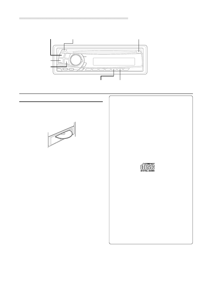
CD Player Operation
- / J
SOURCE
c
Inserting/Ejecting Disc
1
Insert a CD half way into the slot with the label
side facing up. The player automatically draws
the disc into the disc compartment.
The Disc indicator appears to show that a disc
is loaded.
NOTE
Three-inch (8cm) CD's can be used.
2
Press the c button when you want to eject the
CD.
NOTES
• If the CD is not removed for several seconds after it
has been ejected, the player automatically draws the
CD into the compartment to protect the CD.
• Do not insert or remove a CD when loading or
ejecting a CD, as malfunction may result.
About the usable discs.
We recommend using only compact discs containing
the marks shown below.
You can play CD-Rs (CD-Recordable)/CD-RWs (CD-
ReWritable) for audio use on this unit. You can not also
play CD-Rs/CD-RWs containing MP3 formatted audio
files.
• Some of the following CDs may not play on this unit:
Flawed CDs, CDs with fingerprints, CDs exposed to
extreme temperatures or sunlight (e.g., left in the car
or this unit), CDs recorded under unstable conditions,
CDs not designed for audio use, CDs on which a
recording failed a re-recording was attempted.
On handling Compact Discs (CD/CD-R/
CD-RW)
• Do not touch the surface.
• Do not expose the disc to direct sunlight.
• Do not affix stickers or labels and do not write on the
surface.
• Clean the disc when it is dusty.
• Make sure that there are no bumps around thedisc.
• Do not use commercially available disc accessories.
Do not leave the disc in the car or the unit for a
long time. Never expose the disc to direct sunlight.
Heat and humidity may damage the CD and you may
not be able to play it again.
g DN
f UP
M.I.X.
REPEAT
13
-EN
Normal Play and Pause
1
Insert a CD. The CD player begins playback from
the first track on the disc.
The display shows the track number and
elapsed time of the track being played. When
the last track is played back the player returns
to the first track.
2
If a disc is already loaded in the CD player, press
the SOURCE button to select the CD mode.
3
Press the -/J button to temporarily stop CD
playback.
To resume playback, press the -/J button
again.
Music Sensor (Skip)
1
Momentarily press the g DN button once
during CD play to return to the beginning of the
current track. If you wish to access a track further
back, repeatedly press until you reach the
desired track.
Press the f UP button once to advance to the
beginning of the next track. If you wish to access
a track further ahead, press repeatedly until the
desired track is reached.
NOTE
The music sensor feature is functional in the play or
pause mode.
Fast Forward and Backward
1
Press and hold the g DN or f UP button
to quickly move backward or forward until you
reach the desired section of the track.
Repeat Play
1
Press the REPEAT button to play back
repeatedly the track being played.
The RPT indicator appears and the track will be
played repeatedly.
Press the REPEAT button again to deactivate
the repeat play.
NOTES
• If a CD Changer is connected and the RPT ALL
mode is selected, the unit repeatedly plays back all
tracks on the disc selected (CDM-7874R/CDM-
7872R/CDM-7871R only).
• In case a 6-disc CD changer is connected (CDM-
7874R/CDM-7872R/CDM-7871R only):
Press the F button so that the "FUNC" indicator
lights up, then go to step 1.
Press the F button to return to the normal mode.
The "FUNC" indicator light goes out.
M.I.X. (Random Play)
1
Press the M.I.X. button in the play or pause
mode.
The M.I.X. indicator will illuminate and the tracks
on the disc will be played back in a random
sequence.
To cancel M.I.X. play, press the M.I.X. button again.
NOTE
In case a 6-disc CD changer is connected (CDM-
7874R/CDM-7872R/CDM-7871R only):
Press the F button so that the "FUNC" indicator lights
up, then go to step 1.
Press the F button to return to the normal mode.
The "FUNC" indicator light goes out.
RPT
RPT ALL
(OFF)
→
→
→
14
-EN
Scanning Programmes
1
Press the SCAN button to activate the Scan
mode.
The first 10 seconds of each track will be played
back in succession.
To stop scanning, press the SCAN button to
deactivate the Scan mode.
NOTE
In case a 6-disc CD changer is connected (CDM-
7874R/CDM-7872R/CDM-7871R only):
Press the F button so that the "FUNC" indicator lights
up, then go to step 1.
Press the F button to return to the normal mode.
The "FUNC" indicator light goes out.
Controlling CD Changer (Optional)
(CDM-7874R/CDM-7872R/CDM-
7871R only)
If an optional Alpine 6-disc CD Changer is
connected to the 8-pin DIN connector (M-Bus) of
the CDM-7874R/CDM-7872R/CDM-7871R, you
can control the CD Changer using the CDM-
7874R/CDM-7872R/CDM-7871R.
NOTE
The CD controls on the CDM-7874R/CDM-7872R/
CDM-7871R for the CD Changer operation are
functional only when the CD Changer is interconnected
with the CDM-7874R/CDM-7872R/CDM-7871R.
1
Press the SOURCE button to activate the CD
Changer.
The display shows "changer", the disc number
and track number.
NOTE
To start play or pause play, press the :/J button.
2
Make sure that the "FUNC" indicator light goes
out, then press the Preset buttons to select the
desired disc loaded in the CD Changer.
NOTES
• After selecting the desired disc, you can operate in
the same way as for the CD player.
For details, please see the CD Operation section.
• If the "FUNC" indicator is illuminated the Disc
Select buttons become nonfunctional.
CD Player Operation
- / J
SOURCE
Preset
SCAN
15
-EN
Subwoofer On and Off
1
Press and hold the SETUP button for at least 3
seconds.
2
Press the g DN or f UP button to select
the SUB-W mode.
3
Press the BAND button to select Subwoofer ON
or OFF.
4
After setting is completed, press the SETUP
button to return to normal mode.
NOTES
• Initial mode is "Subwoofer ON."
• Set to "Subwoofer OFF" unless the subwoofer is
used.
• When the subwoofer is turned on, the subwoofer
output level can be adjusted. For more details, refer
to the Adjusting Volume/Balance/Fader.
Adjusting Source Signal Levels
If the difference in volume level between the CD
player and FM radio is too great, adjust the FM
signal level as follows.
1
Press and hold the SETUP button for at least 3
seconds.
2
Press the g DN or f UP button to select
the FM LV (FM LEVEL) mode.
3
Press the BAND button to select the FM signal
level HI (High) or LO (Low) to make the signal
levels between the FM band and CD player
closer.
4
Press the SETUP button to return to normal
mode.
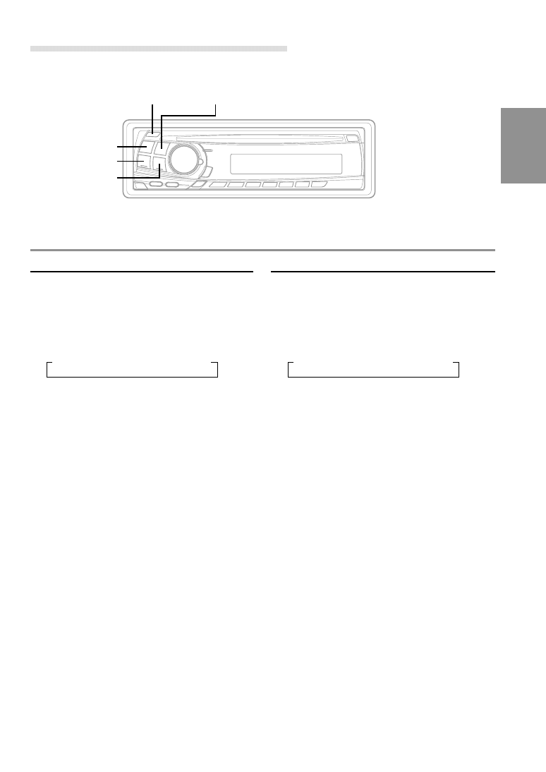
Changing Audio Level Display
Pattern
1
Press the SETUP button for at least 3 seconds.
2
Press g DN or f UP button to select the
DISP mode.
3
Press BAND button to switch the display pattern.
DISP1:
Lights the Volume indicator.
DISP2:
Lights the mode and value bars to show the
settings in the Bass engine display.
NOTE
The last mode set will remain in effect. The mode and
value bars light and show the Bass engine settings.
DISP OFF:
Turns off the light in Bass engine display.
If you set DISP OFF, the Volume indicator, Audio
Level indicator, and Bass engine displays are not
lit at all times.
4
Press the SETUP button to return to normal
mode.
Example settings:
Bass center frequency: 100 Hz
Bass band width: WIDE1
Bass level: - 6
→ DISP1 → DISP2 → DISP OFF
SETUP Operation
BAND
f UP
g DN
SETUP
Volume indicator
16
-EN
Switching the Tuner Mode
The CDM-7874R/CDM-7872R/CDM-7871R/CDE-
7860R incorporates the MAX TUNE Pro for the
highest quality tuner audio. Moreover, you can
choose between 3 settings to suit your own
personal sound preferences usage.
1
Press and hold the SETUP button for at least 3
seconds.
2
Press the g DN or f UP button to select
NORMAL.
3
Press the BAND button to switch the TUNER
mode.
NORMAL: Standard setting
HI-FI: Sound quality priority setting
STABLE: Noiseless priority setting
NOTES
• The initial setting at the factory is "NORMAL."
• If you find the sound is very noisy while listening to
the tuner in the HI-FI mode, we recommend you
change to the NORMAL mode.
4
When the setting is completed, press the SETUP
button to return to the normal mode.
→ HI-FI → NORMAL → STABLE
SETUP Operation
Setting the AUX Mode
(CDM-7874R/CDM-7872R/CDM-
7871R only)
You can input TV/video sound by connecting an
optional "M-Bus V-Link" (M-Bus/RCA interface
cable KCM-122B) to this component.
1
Press and hold the SETUP button for at least 3
seconds.
2
Press the g DN or f UP button to select
the AUX mode.
3
Press the BAND button to toggle the mode
between AUX ON and AUX OFF.
4
Press the SETUP button to return to normal
mode.
5
To adjust the volume, etc., first press the
SOURCE button and select the AUX mode, then
make the necessary adjustment.
→ TUNER → CD → AUX
NOTE
When AUX ON is selected, a CD Changer cannot be
used.
BAND
f UP
g DN
SETUP
SOURCE

17
-EN
Information
In Case of Difficulty
If you encounter a problem, please turn the power
off, then on again. If the unit is still not functioning
normally, please review the items in the following
checklist. This guide will help you isolate the
problem if the unit is at fault. Otherwise, make
sure the rest of your system is properly connected
or consult your authorized Alpine dealer.
Basic
No function or display.
• Vehicle's ignition is off.
- If connected following instructions, the unit will not
operate with the vehicle's ignition off.
• Improper power lead connections.
- Check power lead connections.
• Blown fuse.
- Check the fuse on the battery lead of the unit; replace
with the proper value if necessary.
• Internal micro-computer malfunctioned due to
interference noise etc.
- Press the Reset switch with a ballpoint pen or other
pointed article.
Radio
Unable to receive stations.
• No antenna or open connection in cable.
- Make sure the antenna is properly connected;
replace the antenna or cable if necessary.
Unable to tune stations in the seek mode.
• You are in a weak signal area.
- Make sure the tuner is in the DX mode.
• If the area you are in is a primary signal area, the
antenna may not be grounded and connected properly.
- Check your antenna connections; make sure the
antenna is properly grounded at its mounting
location.
• The antenna may not be the proper length.
- Make sure the antenna is fully extended; if
broken, replace the antenna with a new one.
Broadcast is noisy.
• The antenna is not the proper length.
- Extend the antenna fully; replace it if it is broken.
• The antenna is poorly grounded.
- Make sure the antenna is grounded properly at its
mounting location.
CD
CD Player/Changer (CDM-7874R/CDM-7872R/
CDM-7871R only) not functioning.
• Out of operating temperature range +50˚C (+120˚F) for
CD.
- Allow the vehicle's interior (or trunk) temperature to
cool.
CD playback sound is wavering.
• Moisture condensation in the CD Module.
- Allow enough time for the condensation to evaporate
(about 1 hour).
CD insertion not possible.
• The CD is already in the CD player.
- Eject the CD and remove it.
• The CD is being improperly inserted.
- Make sure the CD is being inserted following
instructions in the CD Player Operation section.
Unable to fast forward or backward the CD.
• The CD has been damaged.
- Eject the CD and discard it; using a damaged CD in
your unit can cause damage to the mechanism.
CD playback sound skips due to vibration.
• Improper mounting of the unit.
- Securely re-mount the unit.
• Disc is very dirty.
- Clean the disc.
• Disc has scratches.
- Change the disc.
• The pick-up lens is dirty.
- Do not use a commercial available lens cleaner disc.
Consult your nearest ALPINE dealer.
CD playback sound skips without vibration.
• Dirty or scratched disc.
- Clean the disc; damaged disc should be replaced.
Error displays (built-in CD player only)
• Mechanical error
- Press the c button. After the error indication
disappears, insert the disc again. If the above-
mentioned solution does not solve the problem,
consult your nearest ALPINE dealer.

18
-EN
HI TEMP
ERROR
Indication for CD
• Protective circuit is activated due to high temperature.
- The indicator will disappear when the temperature
returns to within operation range.
• Mechanism error.
1. Press the c button and eject the CD.
If not ejecting, consult your Alpine dealer.
2. When the error indication remains after ejecting,
press the c button again.
If the error indication still does not turn off after pressing
the c button for a few times, consult your Alpine dealer.
Note
When the "ERROR" is displayed:
In case that the disc cannot be ejected by pressing the c
button, press the Reset switch (refer to page 4) and press the
c button again.
If not ejecting, consult your Alpine dealer.
• No CD is inserted.
- Insert a CD.
Indication for CD Changer
(CDM-7874R/CDM-7872R/CDM-7871R
only)
• Protective circuit is activated due to high temperature.
- The indicator will disappear when the temperature
returns to within operation range.
• Malfunction in the CD Changer.
- Consult your Alpine dealer. Press the magazine eject
button and pull out the magazine.
Check the indication. Insert the magazine again.
If the magazine cannot be pulled out, consult your
Alpine dealer.
• Magazine ejection not possible.
- Press the magazine eject button. If the magazine does
not eject, consult your Alpine dealer.
NO DISC
HI TEMP
ERROR - 01
NO MAGZN
NO DISC
• No magazine is loaded into the CD Changer.
- Insert a magazine.
• No indicated disc.
- Choose another disc.
Information

19
-EN
Specifications
FM TUNER SECTION
Tuning Range
87.5 – 108.0 MHz
Mono Usable Sensitivity
0.7 µV
Alternate Channel Selectivity 80 dB
Signal-to-Noise Ratio
65 dB
Stereo Separation
35 dB
MW TUNER SECTION
Tuning Range
531 – 1,602 kHz
Sensitivity (IEC Standard)
25.1 µV/28 dB
LW TUNER SECTION
Tuning Range
153 – 281 kHz
Sensitivity (IEC Standard)
31.6 µV/30 dB
CD SECTION
Frequency Response
5 – 20,000 Hz (±1 dB)
Wow & Flutter (% WRMS)
Below measurable limits
Total Harmonic Distortion
0.008% (at 1 kHz)
Dynamic Range
95 dB (at 1 kHz)
Signal-to-Noise Ratio
105 dB
Channel Separation
85 dB (at 1 kHz)
PICKUP
Wave Length
795 nm
Laser power
CLASS I
CAUTION
CLASS 1
LASER PRODUCT
(Bottom side of player)
GENERAL
Power Requirement
14.4 V DC
(11–16 V allowable)
Maximum Power Output
50 W x 4 (CDM-7874R
only)
45 W
× 4 (CDM-7872R/
CDM-7871R/CDE-7860R
only)
Output Voltage
2 V/10k ohms
Bass
±14 dB at 60 Hz
Treble
±14 dB at 10 kHz
Weight
1.5 kg (3 lbs. 5 oz)
CHASSIS SIZE
Width
178 mm (7")
Height
50 mm (2")
Depth
155 mm (6-1/8")
NOSEPIECE SIZE
Width
170 mm (6–3/4")
Height
46 mm (1-13/16")
Depth
20 mm (25/32")
Due to continuous product improvement, specifications and
design are subject to change without notice.
20
-EN
Installation and Connections
Before installing or connecting the unit, please
read the following and pages 2 and 3 of this
manual thoroughly for proper use.
Warning
MAKE THE CORRECT CONNECTIONS.
Failure to make the proper connections may result in fire
or product damage.
USE ONLY IN CARS WITH A 12 VOLT NEGATIVE
GROUND.
(Check with your dealer if you are not sure.) Failure to do
so may result in fire, etc.
BEFORE WIRING, DISCONNECT THE CABLE FROM
THE NEGATIVE BATTERY TERMINAL.
Failure to do so may result in electric shock or injury due
to electrical shorts.
DO NOT SPLICE INTO ELECTRICAL CABLES.
Never cut away cable insulation to supply power to other
equipment. Doing so will exceed the current carrying
capacity of the wire and result in fire or electric shock.
DO NOT DAMAGE PIPE OR WIRING WHEN
DRILLING HOLES.
When drilling holes in the chassis for installation, take
precautions so as not to contact, damage or obstruct pipes,
fuel lines, tanks or electrical wiring. Failure to take such
precautions may result in fire.
DO NOT USE BOLTS OR NUTS IN THE BRAKE OR
STEERING SYSTEMS TO MAKE GROUND
CONNECTIONS.
Bolts or nuts used for the brake or steering systems (or
any other safety-related system), or tanks should NEVER
be used for installations or ground connections. Using
such parts could disable control of the vehicle and cause
fire etc.
DO NOT INSTALL IN LOCATIONS WHICH MIGHT
HINDER VEHICLE OPERATION, SUCH AS THE
STEERING WHEEL OR GEARSHIFT.
Doing so may obstruct forward vision or hamper
movement etc. and results in serious accident.
Caution
HAVE THE WIRING AND INSTALLATION DONE BY
EXPERTS.
The wiring and installation of this unit requires special
technical skill and experience. To ensure safety, always
contact the dealer where you purchased this product to
have the work done.
USE SPECIFIED ACCESSORY PARTS AND INSTALL
THEM SECURELY.
Be sure to use only the specified accessory parts. Use of
other than designated parts may damage this unit internally
or may not securely install the unit in place. This may cause
parts to become loose resulting in hazards or product failure.
ARRANGE THE WIRING SO IT IS NOT CRIMPED OR
PINCHED BY A SHARP METAL EDGE.
Route the cables and wiring away from moving parts (like
the seat rails) or sharp or pointed edges. This will prevent
crimping and damage to the wiring. If wiring passes through
a hole in metal, use a rubber grommet to prevent the wire's
insulation from being cut by the metal edge of the hole.
DO NOT INSTALL IN LOCATIONS WITH HIGH
MOISTURE OR DUST.
Avoid installing the unit in locations with high incidence
of moisture or dust. Moisture or dust that penetrates into
this unit may result in product failure.
Precautions
• Be sure to disconnect the cable from the (–) battery post
before installing your CDM-7874R/CDM-7872R/CDM-
7871R/CDE-7860R. This will reduce any chance of damage
to the unit in case of a short-circuit.
• Be sure to connect the colour coded leads according to the
diagram. Incorrect connections may cause the unit to
malfunction or damage to the vehicle's electrical system.
• When making connections to the vehicle's electrical
system, be aware of the factory installed components (e.g.
on-board computer). Do not tap into these leads to provide
power for this unit. When connecting the CDM-7874R/
CDM-7872R/CDM-7871R/CDE-7860R to the fuse box,
make sure the fuse for the intended circuit of the CDM-
7874R/CDM-7872R/CDM-7871R/CDE-7860R has the
appropriate amperage. Failure to do so may result in
damage to the unit and/or the vehicle. When in doubt,
consult your ALPINE dealer.
• The CDM-7874R/CDM-7872R/CDM-7871R/CDE-7860R
uses female RCA-type jacks for connection to other units
(e.g. amplifier) having RCA connectors. You may need an
adaptor to connect other units. If so, please contact your
authorized ALPINE dealer for assistance.
• Be sure to connect the speaker (–) leads to the speaker (–)
terminal. Never connect left and right channel speaker
cables to each other or to the vehicle body.
IMPORTANT
Please record the serial number of your unit in the
space provided below and keep it as a permanent
record. The serial number plate is located on the
bottom of the unit.
SERIAL NUMBER:
INSTALLATION DATE:
INSTALLATION TECHNICIAN:
PLACE OF PURCHASE:
21
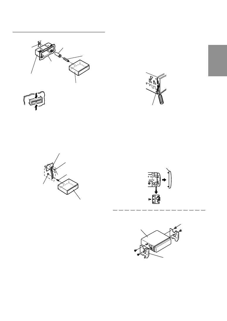
-EN
Lock pin
3
Slide the CDM-7874R/CDM-7872R/CDM-7871R/
CDE-7860R into the dashboard. When the unit is
in place, make sure the locking pins are fully
seated in the down position. This can be done by
pressing firmly in on the unit while pushing the
locking pin down with a small screwdriver. This
ensures that the unit is properly locked and will
not accidentally come out from the dashboard.
Install the Detachable Front Panel.
Removal
1
Remove the detachable front panel.
2
Use a small screwdriver (or similar tool) to
push the locking pins to the “up” position (see
Fig. 3). As each pin is unlocked, gently pull out
on the unit to make sure it does not re-lock
before unlocking the second pin.
3
Pull the unit out, keeping it unlocked as you do so.
<JAPANESE CAR>
Front frame
Dashboard
Installation
1
Remove the Detachable Front Panel (refer to
page 4). Slide mounting sleeve from main unit
(see Removal Procedure below). Slide the
mounting sleeve into the dashboard.
2
When your vehicle has the Bracket, mount the
long hex bolt onto the rear panel of the CDM-
7874R/CDM-7872R/CDM-7871R/CDE-7860R
and put the Rubber Cap on the hex bolt. If your
vehicle does not have the Mounting Support,
reinforce the head unit with the metal mounting
strap (not supplied). Connect all the leads of the
CDM-7874R/CDM-7872R/CDM-7871R/CDE-
7860R according to details described in the
CONNECTIONS section.
NOTE
For the screw
∗, provide a proper screw to the chassis
installing location.
Rubber Cap
(Included)
Bracket
Mounting sleeve
(Included)
CDM-7874R/CDM-7872R/
CDM-7871R/CDE-7860R
Hex Bolt
(Included)
∗
Metal Mounting Strap
Screw
Bolt Stud
Hex Nut (M5)
CDM-7874R/CDM-7872R/
CDM-7871R/CDE-7860R
Screws (M5
× 8)
(Included)
CDM-7874R/CDM-7872R/
CDM-7871R/CDE-7860R
Mounting Bracket
No Pressure Here
No Pressure Here
22
-EN
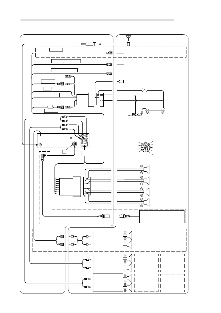
Installation and Connections
Ignition Key
Battery
Subwoofers
Rear Left
Front Left
Front Right
Rear Right
Speakers
A
DIN Connector PIN Configuration
(CDM-7874R/CDM-7872R/CDM-7871R only)
Amplifier
ISO Antenna Plug
Antenna
To power antenna
To vehicle phone
To amplifier or equalizer
Connection
(Pink/Black)
AUDIO INTERRUPT IN
(Blue/White)
REMOTE TURN-ON
(Red)
IGNITION
(Black)
GND
(Blue)
POWER ANT
(Yellow)
BATTERY
Green
Green/Black
White
White/Black
Grey/Black
Grey
Violet/Black
Violet
(Orange)
DIMMER
(CDM-7874R/CDM-7872R only)
Amplifier
Amplifier
Rear (CDM-
7874R only)
Front (CDM-
7874R/CDM-
7872R only)
Rear or
Subwoofers*
(CDM-7872R
only)
Rear or
Subwoofers*
(CDM-7871R/
CDE-7860R
only)
CD changer
(Sold separately)
To the instrument cluster
illumination lead
(CDM-7874R/CDM-7872R/CDM-7871R only)
Rch
Sig Gnd
Lch
Data Ground
Data Bus
Battery
Shield Ground
lgnition
Power Supply Ground
A
=
7
1
4
6
5
3
2
9
!
8
+
,
-
.
~
)
;
/
:
(
&
#
$
"
<
%
>
>
>
(CDM-7874R only)

23
-EN
1 ISO Antenna Convertor Plug
2 Dimmer Lead (Orange)
This lead may be connected to the vehicle’s
instrument cluster illumination lead. This will enable
the vehicle’s dimmer control to dim the backlighting
of the unit.
3 Audio Interrupt In Lead (Pink/Black)
Connect this lead to the Audio Interface output of a
cellular phone which provides ground shorting when
a call is received.
If a device having the interrupt feature is connected,
audio will be automatically muted whenever the
interrupt signal is received from the device.
4 Remote Turn-On Lead (Blue/White)
Connect this lead to the remote turn-on lead of your
amplifier or signal processor.
5 Switched Power Lead (Ignition) (Red)
Connect this lead to an open terminal on the vehicle’s
fuse box or another unused power source which
provides (+) 12V only when the ignition is turned on
or in the accessory position.
6 Ground Lead (Black)
Connect this lead to a good chassis ground on the
vehicle. Make sure the connection is made to bare
metal and is securely fastened using the sheet metal
screw provided.
7 Power Antenna Lead (Blue)
Connect this lead to the +B terminal of your power
antenna, if applicable.
NOTE
This lead should be used only for controlling the
vehicle's power antenna. Do not use this lead to turn on
an amplifier or a signal processor, etc.
8 Fuse Holder (15A)
9 Battery Lead (Yellow)
Connect this lead to the positive (+) post of the
vehicle’s battery.
! ISO Power Supply Connector
" Antenna Receptacle
Connect to the supplied ISO antenna convertor plug.
# Remote Control Interface Connector (CDM-
7874R/CDM-7872R/CDM-7871R only)
To remote control interface box.
$ Front Output RCA Connectors (CDM-7874R/
CDM-7872R only)
RED is right and WHITE is left.
$ Rear/Subwoofer* Output RCA Connectors
(CDM-7871R/CDE-7860R only)
RED is right and WHITE is left.
*
When Subwoofer is set to OFF: Output is from Rear
speakers.
When Subwoofer is set to ON: Output is from Subwoofer.
% Rear Output RCA Connectors (CDM-7874R
only)
RED is right and WHITE is left.
% Rear/Subwoofer* Output RCA Connectors
(CDM-7872R only)
RED is right and WHITE is left.
*
When Subwoofer is set to OFF: Output is from Rear
speakers.
When Subwoofer is set to ON: Output is from Subwoofer.
& Power Supply Connector
( DIN Connector (CDM-7874R/CDM-7872R/CDM-
7871R only)
Connect this to the DIN connector on the CD changer.
) Left Rear (+) Speaker Output Lead (Green)
~ Left Rear (–) Speaker Output Lead (Green/
Black)
+ Left Front (+) Speaker Output Lead (White)
, Left Front (–) Speaker Output Lead (White/Black)
- Right Front (–) Speaker Output Lead (Grey/
Black)
. Right Front (+) Speaker Output Lead (Grey)
/ Right Rear (–) Speaker Output Lead (Violet/
Black)
: Right Rear (+) Speaker Output Lead (Violet)
; ISO Connector (Speaker Output)
< DIN Extension Cable (Included with CD changer)
NOTE
Older Alpine CD changer came with standard, straight
type DIN connectors. In installations where an L-type
connector would simplify installation, the Alpine 4910
02
Adaptor can be used (sold separately).
= Subwoofer Output RCA Connectors (CDM-
7874R only)
RED is right and WHITE is left.
> RCA Extension Cable (sold separately)
To prevent external noise from entering the audio system.
• Locate the unit and route the leads at least 10 cm away from the car harness.
• Keep the battery power leads as far away from other leads as possible.
• Connect the ground lead securely to a bare metal spot (remove any paint, dirt or grease if necessary) of the car
chassis.
• If you add an optional noise suppressor, connect it as far away from the unit as possible. Your Alpine dealer carries
various noise suppressors, contact them for further information.
• Your Alpine dealer knows best about noise prevention measures so consult your dealer for further information.
For details on how to set the Subwoofer to ON/OFF, see "Subwoofer On and Off" on page 15.

24
-EN
Tips der Polizei:
[ Stellen Sie Ihr Fahrzeug stets gut sichtbar ab.
[ Verschließen Sie Türen, Fenster, Schiebedach und Kofferraum immer, auch bei nur kurzer Abwesenheit.
[ Lassen Sie keine Wertsachen sichtbar im Auto liegen.
[ Wird Ihr Fahrzeug aufgebrochen, wenden Sie sich sofort an die nächste Polizeidienststelle.
[ Belassen Sie Ihr Fahrzeug nach einem Aufbruch im Originalzustand.
[ Informieren Sie sich über technische Sicherungsmöglichkeiten bei einer Kriminalpolizeilichen
Beratungsstelle.
Gerät 1
Modell-Nr.:
Hersteller:
Seriennummer:
A
L
Kaufdatum:
Preis:
Händlerstemple

Fahrzeugmarke:
Typ:
Amtl. Kennzeichen:
Name des Halters:
Straße:
Wohnort:
Bitte füllen Sie diesen Pass vollständig aus und bewahren Sie ihn
außerhalb des Fahrzeugs auf:
Im Falle eines Diebstahls wird für Sie die Schadensabwicklung mit der
Versicherung einfacher, und Sie erleichtern der Polizei die Fahndung
nach den Tätern.
R
Car Audio and Navigation Systems
GERÄTE-PASS
AUDIO SYSTEME
Wyszukiwarka
Podobne podstrony:
Alpine MRD M300 Mono ampl Owners Manual
Alpine PXA H510 Digital Audio Processor Owners Manual
Bmw 01 94 Business Mid Radio Owners Manual
MPC The Kit Owners Manual
Oberheim Prommer Owners Manual
Bmw 01 94 Business Mid Radio Owners Manual
Pioneer CS 53 Owners Manual
Kenwood CRS 155 Owners Manual
Nec NDT 42 Owners Manual
Yamaha AX 890 Owners Manual
Gibson LP Standard 2010 Owners Manual 1 0
Pioneer BDP 208DBK Owners Manual
Nec N8151 32B Owners Manual
Yamaha AX 10 Owners Manual
Kenwood Basic M 1 D Owners Manual
Cessna 172 owners manual
więcej podobnych podstron