Shock Waves (1997) 7: 135–145
Shock waves in molecular solids: ultrafast vibrational spectroscopy
of the first nanosecond
J. Franken, S.A. Hambir, D.E. Hare, D.D. Dlott
School of Chemical Sciences, University of Illinois at Urbana-Champaign, Box 01-6 CLSB, 600 S. Mathews Ave., Urbana, IL 61801, USA
Received 28 October 1996 / Accepted 12 November 1996
Abstract. A novel technique which uses a microfabricated
shock target array assembly is described, where the pas-
sage of a shock front through a thin (0
.5 µm) polycrystalline
layer and the subsequent unloading process is monitored in
real time with ultrafast coherent Raman spectroscopy. Us-
ing a high repetition rate laser shock generation technique,
high resolution, coherent Raman spectra are obtained in
shocked anthracene and in a high explosive material, NTO,
with time resolution of
∼ 50 ps. Spectroscopic measure-
ments are presented which yield the shock pressure (up to
5 GPa), the shock velocity (
∼ 4 km/s), the shock front rise-
time (
t
r
< 25 ps), and the temperature (∼ 400
◦
C). A brief
discussion is presented, how this new technique can be used
to determine the Hugoniot, the equation of state, the entropy
increase across the shock front, and monitor shock induced
chemical reactions in real time.
Key words: Vibrational spectroscopy, Picosecond spectros-
copy, Laser-driven shock, Polycrystalline solids
1 Introduction
Vibrational spectroscopy is a powerful technique for inves-
tigating shock wave dynamics in molecular solids (Schmidt
1983). Vibrational spectroscopy can be used as an instanta-
neous probe of the temperature, pressure and composition
of a shocked material (Schmidt 1983). Until recently, all vi-
brational spectroscopic measurements of shock phenomena
have been limited in time resolution to a few tens of ns
(e.g. Holmes 1985; Moore 1991; Pangilinan 1994; Schmidt
1983; Schmidt 1987; Schmidt 1991; Trott 1988; Yoo 1989;
Yoo 1996). We have developed a new method which extends
the time resolution of vibrational spectroscopy of shocked
materials to better than 100 ps (Hambir 1996). In order to
achieve such unprecedented time resolution, it is not enough
simply to use a laser with a short pulse (Hambir 1996). Two
other significant obstacles must be overcome. First, some
method has to be used which probes only a very thin layer
behind the shock front. In 100 ps, shock waves in condensed
Correspondence to: D.D. Dlott, e-mail: d-dlott@uiuc.edu
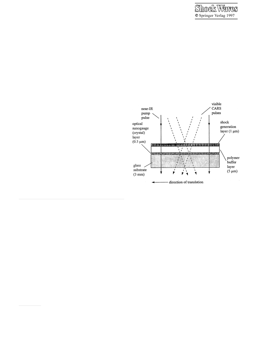
Fig. 1. Schematic diagram of the shock target array assembly. The CARS
pulses probe a volume at the center of the near-IR pump pulse. After each
shock event, the target array is translated to expose a fresh volume. A single
target array has
∼ 10
6
identical shock elements, and it contains a few mg
of polycrystalline sample material
matter propagate only a short distance, say 0
.4 µm for a typi-
cal shock velocity of 4 km/s, which is less than a wavelength
of visible light. The probe technique used must have high
spatial resolution, since any technique with spatial resolu-
tion worse than a wavelength will greatly degrade the time
resolution. Second, the arrival time of the shock front at the
region being probed must be highly reproducible and known
very accurately.
Our solution to these problems involves a microfabri-
cated shock target array assembly which contains a very thin
layer, termed an optical nanogauge (Lee 1994; Lee 1995).
The shock target array technique is diagrammed schemat-
ically in Fig. 1. The term nanogauge refers to the sub-
micrometer thickness of the layer or alternatively a time
response better than a nanosecond. We launch a shock wave
with an exploding shock generation layer (Hambir 1996;
Hare 1995a) pumped by an intense picosecond duration
near-infrared (near-IR) laser pulse. Only modest laser en-
ergies (
∼ 125 µJ) are needed to produce sizable (5 GPa)

136
shock waves. The shock front propagates first through a thin
polymer buffer layer and subsequently through the optical
nanogauge layer. In the present work, the nanogauge is a
thin layer of a polycrystalline molecular solid. At various
times after the shock pulse is launched, a pair of laser pulses
is used to generate a multiplex broadband coherent Raman
(CARS) spectrum (Eesley 1981; Hare 1994) of the shocked
region. The array has a large area consisting of
∼ 10
6
iden-
tical shock elements. It is scanned through the laser pulses
using a motorized positioner, so that every laser shot hits a
fresh identical target element. This scheme provides efficient
signal averaging at a high repetition rate (typically
∼ 100
shocks per second), giving extremely high signal-to-noise
vibrational spectra.
In a recently submitted paper (Hambir 1996), we de-
scribed this technique and its application to the study of
2.6 GPa shock waves in crystalline anthracene. We showed
that high resolution CARS spectra could be obtained which
allowed for the first time the detailed study of the vibrational
lineshape. We showed that the frequency shift of the most
intense anthracene CARS transition could be used for in-
stantaneous determination of the shock pressure. The shock
wave velocity was determined using a series of target arrays
with different thickness buffer layers. The risetime of the
shock front and the steepening of the risetime as the shock
passed through the buffer layer were measured.
In the previous work (Hambir 1996), the risetime of the
shock front
t
r
≈ 400 ps, which was greater than the shock
front transit time through the optical nanogauge,
t
tr
≈ 125 ps.
Since then we have made considerable improvements in the
shock generation technique, resulting in shock fronts whose
risetime
t
r
is considerably less than the shock transit time
t
tr
≈ 125 ps. As shown below in Section III, this extremely
desirable situation gives rise to a qualitatively different re-
sponse of the nanogauge, permitting us to monitor the prop-
agation of the shock front through the nanogauge in real
time. The shock pressures we can generate at high repetition
rates have been improved to
∼ 5.0 GPa. Finally, improve-
ments in array fabrication methods have been made so that
nearly almost any polycrystalline molecular material may
now be studied, including technologically significant mate-
rials such as high explosives. We illustrate this point with
shock spectroscopy of the insensitive high explosive NTO
(3-nitro-1,2,4-triazol-5-one) (Beardall 1966).
2 Experimental section
The laser system, consisting of a Nd:YAG laser and two dye
lasers, has been described in detail previously (Hambir 1996;
Hare 1994). The shock generation layer is pumped by 150 ps
duration near-IR (
λ = 1.064 µm) pulses of 120 µJ energy, fo-
cused to a 100
µm diameter spot. We produce a shock front
which remains planar at all relevant times (Hambir 1996),
since in the experiments the front propagates at most a few
µm through the target array. Broadband multiplex CARS
spectra are obtained by focusing the dye laser pulses to a
50
µm diameter spot at the center of the shocked volume.
The duration of the dye laser probe pulses is
∼ 50 ps. CARS
spectra are obtained over a frequency region of
∼ 150 cm
−1
,
limited by the spectral bandwidth of the broadband dye laser.
The displayed spectra represent the average of
∼ 5000 laser
shots, acquired using a CCD detector with an integration
time of 60 s. The crystalline nanogauge materials used here
have relatively sharp and intense CARS transitions, which
makes them easy to detect against a background due to the
buffer layer and glass. However a spectral correction tech-
nique can be employed (Hambir 1996), which uses reference
spectra obtained from otherwise identical target arrays with-
out nanogauge layers, to remove spectral contributions from
the buffer layer and the glass, leaving only the contribution
from the crystal nanogauge layer.
Fabrication of an anthracene array was discussed previ-
ously (Hambir 1996). Here we concentrate on the improved
shock generation layer, and illustrate how materials other
than anthracene can be incorporated, using NTO as a spe-
cific example.
The substrates are slabs of float glass 10
× 10 × 0.3 cm
3
.
The nominal 0
.5 µm thick crystalline layers were applied by
spraying an acetone solution of the nanogauge material with
an air brush (Badger Corp.), to produce a relatively dense
layer of sub micrometer polycrystals (Hambir 1996). The
buffer layer polymer, nominally 5
µm thick, was deposited
over the crystals by spin coating. The choice of buffer mate-
rial is dictated by the solubility of the crystal layer, since the
buffer deposition process must not dissolve the underlying
crystal layer. For anthracene, which is insoluble in water, the
buffer layer was applied using an aqueous solution of poly-
vinyl alcohol (PVA). For NTO, which is soluble in water but
insoluble in chloroform, the buffer layer was applied using
a chloroform solution of poly-methyl acrylate (PMMA).
The shock layer consisted of PMMA doped with a near-
IR absorbing dye, IR-165 (Exciton Corp., Dayton, Ohio). A
solution of PMMA described previously (Hambir 1996) was
used, except the PMMA concentration was reduced to 5 vol-
ume percent. The IR-dye concentration was 30 mg/ml. After
spinning at 1500 RPM for 25s, a layer is produced with
a thickness of 1
.2 ± 0.1 µm. In some experiments, shock
layers were fabricated with an addition of a high explosive
to boost the shock pressure. The explosive used was RDX
(hexahydro-1,3,5-trinitro-1,3,5-triazine), which was added to
the shock layer solution at a concentration of 35 mg/ml. The
use of high explosive additives in shock generation layers
will be discussed in more detail in a subsequent paper. Note
that in its entirety, a single shock target array assembly con-
tains no more than a few mg of explosive materials.
3 Response of anthracene to shock
Anthracene (C
14
H
10
) and its close relative naphthalene
(C
10
H
8
) serve as model systems for molecular solids, and
their properties have been studied extensively (Dlott 1988;
Kitaigorodskii 1973). In this discussion, we focus primar-
ily on the use of the
ν
6
anthracene vibrational transition,
at nominal Raman shift of 1404 cm
−1
, which arises from
an intensely Raman-active totally symmetric ring stretch-
ing mode (Abasbegovic 1964), to determine the pressure
P
of the shock front and the temperature
T behind the front
(Hambir 1996). The idea is that the frequency shift
∆ν of
this transition can be used to determine the pressure, and the
137
spectral peak width
∆ can be used to determine the tempera-
ture. Of course there will always be some cross-talk between
these two variables, which we believe under conditions used
here to be minimal for this particular system (Hambir 1996).
We have studied the
ν
6
Raman transition as a function of
pressure at ambient temperature, and as a function of temper-
ature at ambient pressure (Hambir 1996). When anthracene
is compressed, the frequency shifts to the blue (Hambir
1996; Nicol 1975). When anthracene is heated at constant
pressure, a small frequency redshift is observed (Hambir
1996). That redshift does not indicate an explicit depen-
dence of
∆ν on temperature. Instead it can be explained
as a consequence of thermal expansion (Hambir 1996; Hess
1980). Heating the anthracene causes the crystal to expand,
and the density to decrease. By knowing the coefficient of
volume expansion and the dependence of frequency shift
on density, it can be shown that the temperature dependent
redshift is almost totally due to the density change (Hess
1980). Thus the shift
∆ν is primarily dependent on the an-
thracene intermolecular separation, that is the density, and
any temperature-dependence of the shift is actually due to
the temperature dependence of the density.
The spectral width
∆ is a measure of the rate of vibra-
tional dephasing processes (Dlott 1988). Our experiments
showed that when anthracene is compressed at constant
T ,
∆ does not change, but when anthracene is heated, ∆ in-
creases with increasing temperature (Hambir 1996). Thus
∆
is independent of
P , depending only on T . A more detailed
discussion of mechanisms of temperature dependent vibra-
tional dephasing in molecular solids can be found in Dlott
(1988).
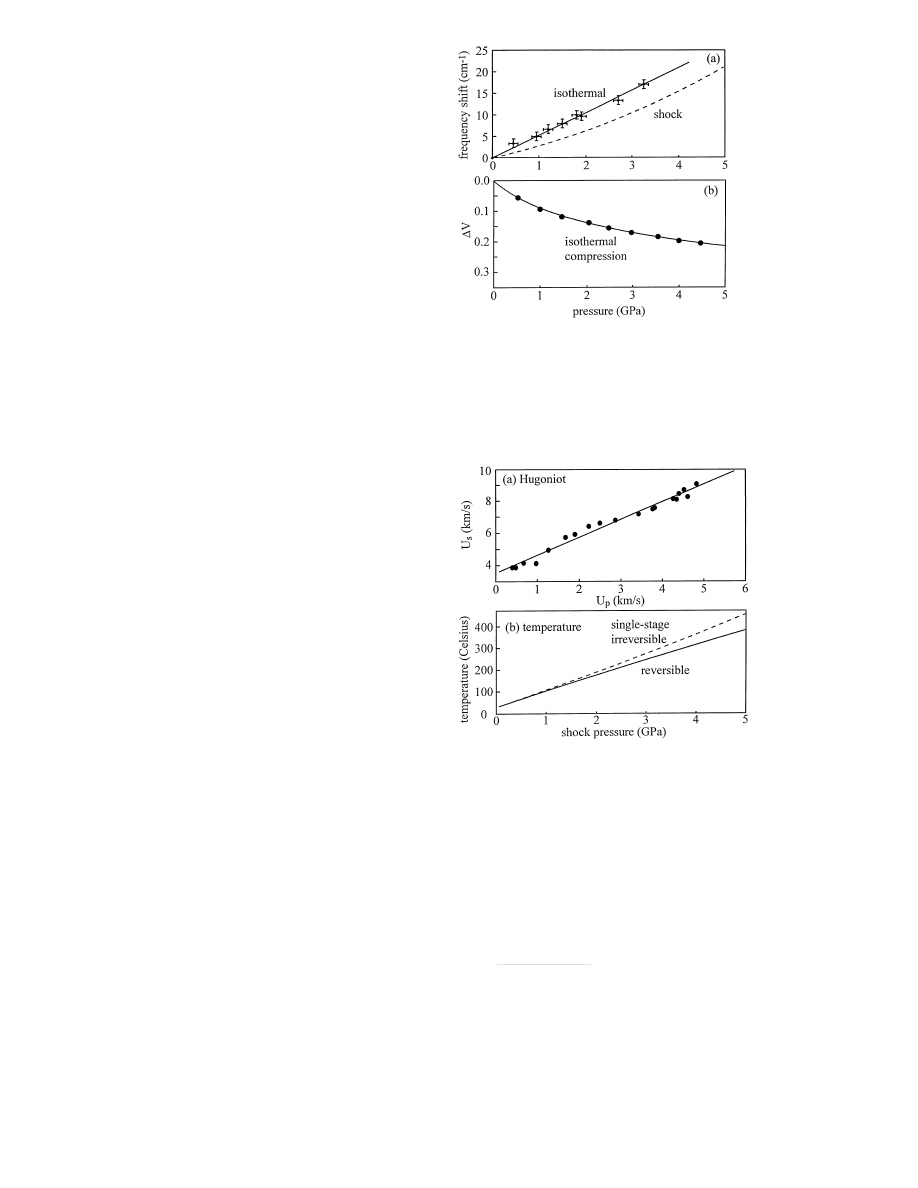
Figure 2a is a plot of the isothermal frequency blueshift
of anthracene
ν
6
versus
P at ambient temperature. This
data, taken from Hambir (1996), was obtained by compres-
sion in a diamond anvil apparatus with a hydrostatic pres-
sure medium. The blueshift is an apparently linear func-
tion of pressure which is fit by the relation, shift (cm
−1
) =
5
.28P (GPa).
To relate isothermal compression data to shock compres-
sion experiments, we rely on the ansatz that the frequency
shift depends on density alone. We use published data on an-
thracene to determine the relationships between isothermal
compression and density, and between density and shock
pressure.
First we convert the isothermal shift vs. pressure data
to shift vs. density. That is accomplished using the isother-
mal compression data of Vaidya (1971), which is plotted in
Fig. 2b. A smooth curve is fit to their data, using a Mur-
naghan equation (Vaidya 1971),
P
isoth
= (1
− ∆V )
−β
+
A ,
(1)
where
∆V is the fractional volume change, ∆V = (V
0
−
V
1
)
/V
0
. For anthracene
ν
6
, the best fit to the data gave the
parameters
β = 7.4 and A = 1.0. The smooth fit to the
compressibility data is shown in Fig. 2b.
Shock Hugoniot data are usually given in the form
(Marsh 1980),
U
s
=
b + mU
p
,
(2)
where
U
s
is the shock velocity and
U
p
the particle velocity.
In Fig. 3a we plot the anthracene Hugoniot data of Warnes
Fig. 2. a Experimental measurements (crosses) of the peak blueshift
∆ν
of the anthracene
ν
6
vibrational transition at ambient temperature and at
the indicated pressures, taken from Hambir (1966). The dashed curve is
a calculation of the relationship between shock pressure and
ν
6
frequency
blueshift. b Experimental measurements (points) of the isothermal change in
relative volume,
∆V , at the indicated pressures, taken from Vaidya (1971).
The smooth curve is a fit to the Murnaghan equation
Fig. 3. a Experimental shock Hugoniot data on anthracene, taken from
Warnes (1970), with the best (linear) fit to Eq. 2. b Calculation of adia-
batic temperature jump (initial temperature
T
0
= 25
◦
C) in anthracene for a
reversible compression (solid line) and for a fast single-stage compression
(dashed line)
(1970). These data were fit to Eq. (2) using the parameters,
b = 3.54 km/s and m = 1.11, as shown in Fig. 3a. Now we
know the shift
∆ν for a given ∆V , and the corresponding
shock pressure corresponding to this
∆V is given by (Marsh
1980),
P
sh
=
b
2
∆V
V
0
(
m∆V − 1)
2
.
(3)
The computed relationship between peak shift
∆ν and
shock pressure is plotted in Fig. 2a. The shock pressure
needed to produce a given peak shift is greater than the
isothermal pressure, due to the temperature increase across
the shock front.
138
The temperature increase across the shock front is given
by (Zel’dovich 1966),
T
1
=
T
0
exp(
Γ ∆V ) + ∆T
irr
,
(4)
where
Γ is the Gr¨uneisen parameter. In Eq. 4, the first term
is the temperature increase for a reversible adiabatic com-
pression and the second term is the additional temperature
increase due to the irreversible entropy increase across the
shock front. This latter term is dependent on the path. It is
maximal for a fast single-stage compression, and for a multi-
stage or very slow compression it tends to zero (Zel’dovich
1966). In our experiments, the crystal nanogauge layer at
T
0
is first subjected to a fast adiabatic irreversible (shock)
compression, followed by a slower adiabatic reversible ex-
pansion (Hare 1995b). As discussed in Sect. 6.2, immediately
after the compression and expansion processes, the temper-
ature of the nanogauge layer is very nearly
T
0
+
∆T
irr
.
Shock temperature calculations are notoriously unreli-
able, so the calculation here is presented for now merely
as a reasonable estimate of the temperature. In the usual
manner, we assume
Γ is independent of T , and that Γ in-
creases linearly with volume, so the ratio
Γ/V is a constant
(Zel’dovich 1966; Tokmakoff 1993). We do not know
Γ for
anthracene, but the value for naphthalene
Γ = 4 (Kitaigorod-
skii 1973) is a reasonable first guess. In Fig. 3b, we plot the
reversible adiabatic temperature increase versus shock pres-
sure. This calculation uses the temperature-dependent heat
capacity (Tokmakoff 1993) given in Domalski (1984). Using
an expression given in Tokmakoff (1993), we also compute
and plot in Fig. 3b the temperature increase for single-stage
irreversible shock compression of anthracene.
4 Simulations of Raman spectra
It is important to keep in mind that the CARS probe provides
a snapshot with an
∼ 50 ps time window, of the entire crystal
nanogauge layer. When the rising shock front is within the
crystal layer, the CARS spectrum reflects the instantaneous
distribution of pressures in the layer (Hambir 1996). In this
section we present a brief qualitative description of shock
propagation through the target array, and some simulations
of time-dependent CARS spectra needed to understand the
experiments.
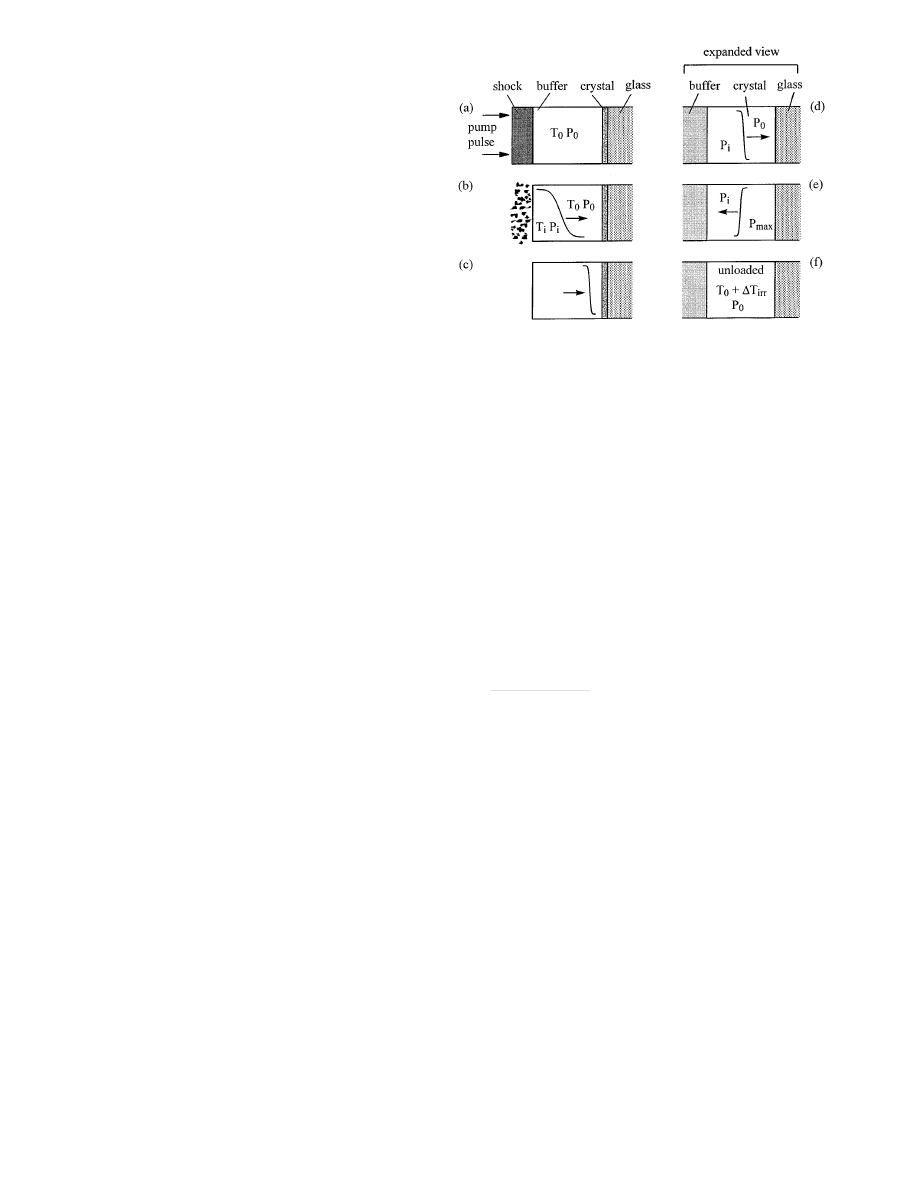
Figure 4 is a schematic representation of the processes
involved in the shock wave experiment. In Fig. 4a, the 150 ps
duration near-IR pump pulse heats the shock generation layer
so fast the volume has almost no time to increase, result-
ing in a sudden pressure jump. Most of the pressure rise
in the shock generation layer is due to thermochemical de-
composition of the PMMA polymer (Hare 1995a) and, if
present, the RDX. The rapid expansion of the shock gener-
ation layer launches a shock into the buffer layer. As shown
in Fig. 4b, the shock layer then ablates away. With the im-
proved shock layer design used here, the initial risetime of
the shock front is probably comparable to the pump pulse du-
ration of
∼ 150 ps. However as the shock propagates through
the buffer layer (Fig. 4c), the front steepens up (Cottet 1982;
Hambir 1996), so the risetime of the shock front incident
on the nanogauge layer can be shorter than the pump pulse
duration.
Fig. 4a–f. Schematic representation of processes involved in the shock
technique. After the shock generation layer is pumped a, the layer ablates,
launching a slower rise time shock into the buffer layer b. The shock front
steepens c. In the expanded view (d–f), the incident shock with pressure
P
i
moves through the crystal nanogauge layer initially at
T
0
, P
0
d. After
reflection from the glass substrate e, the pressure behind the reflected front
increases to
P
max
. After the shock unloads f, the crystal nanogauge layer
has been subjected to an irreversible two-stage shock compression and a
reversible expansion. The final temperature is
T
0
+
∆T
irr
The layers of the array are reasonably well matched in
shock impedance (e.g. PMMA, PVA, anthracene) except for
the glass substrate, which has a much larger impedance. The
crystal layer adjacent to the glass sees a two-step shock
(Hambir 1996) (Figs. 4d,e) consisting of an incident shock
of pressure
P
i
and a reflected shock with pressure
P
r
. After
the two-step shock the steady shock load is
P
max
=
P
i
+
P
r
(Fig. 4e). The pressure
P
r
of a shock reflected from an inter-
face between materials with shock impedances
Z
a
and
Z
b
is (Cagnoux 1987),
P
r
=
P
i
[(
Z
a
/Z
b
)
− 1]
(
Z
a
/Z
b
) + 1
,
(5)
where
P
i
is the incident pressure, and the shock impedance
Z = ρc, where ρ is the density and c the acoustic velocity.
For anthracene and glass,
Z
glass
/Z
anth
≈ 7 (Marsh 1980),
so the reflected shock pressure is
P
r
≈ 0.75P
i
. In subse-
quent discussions, it will be essential to remember there
are three pressures in the experiment:
P
0
the ambient pres-
sure,
P
i
the pressure of the incident shock front, and
P
max
,
the pressure behind the reflected shock front. In our system
P
i
≈ 0.57P
max
.
As described in Sect. 3, after the cycle of irreversible
shock compression and reversible unloading, the tempera-
ture in the crystal nanogauge layer is about
T
0
+
∆T
irr
(Eq. 4).
Ultimately the crystal layer cools back to ambient temper-
ature via thermal conduction to the substrate, which occurs
on the 10
µs time scale (Hambir 1996).
The simulated spectra are computed in two limiting
cases. In the first case, the crystal layer is subjected to a
shock with a risetime in the fast limit, where
t
r
t
tr
. In the
second case the crystal layer is subjected to a shock with
risetime in the slow limit
t
r
> t
tr
. The specific parameters
used here are
t
tr
= 120 ps and
t
r
= 10 ps (fast) or
t
r
= 400 ps
139
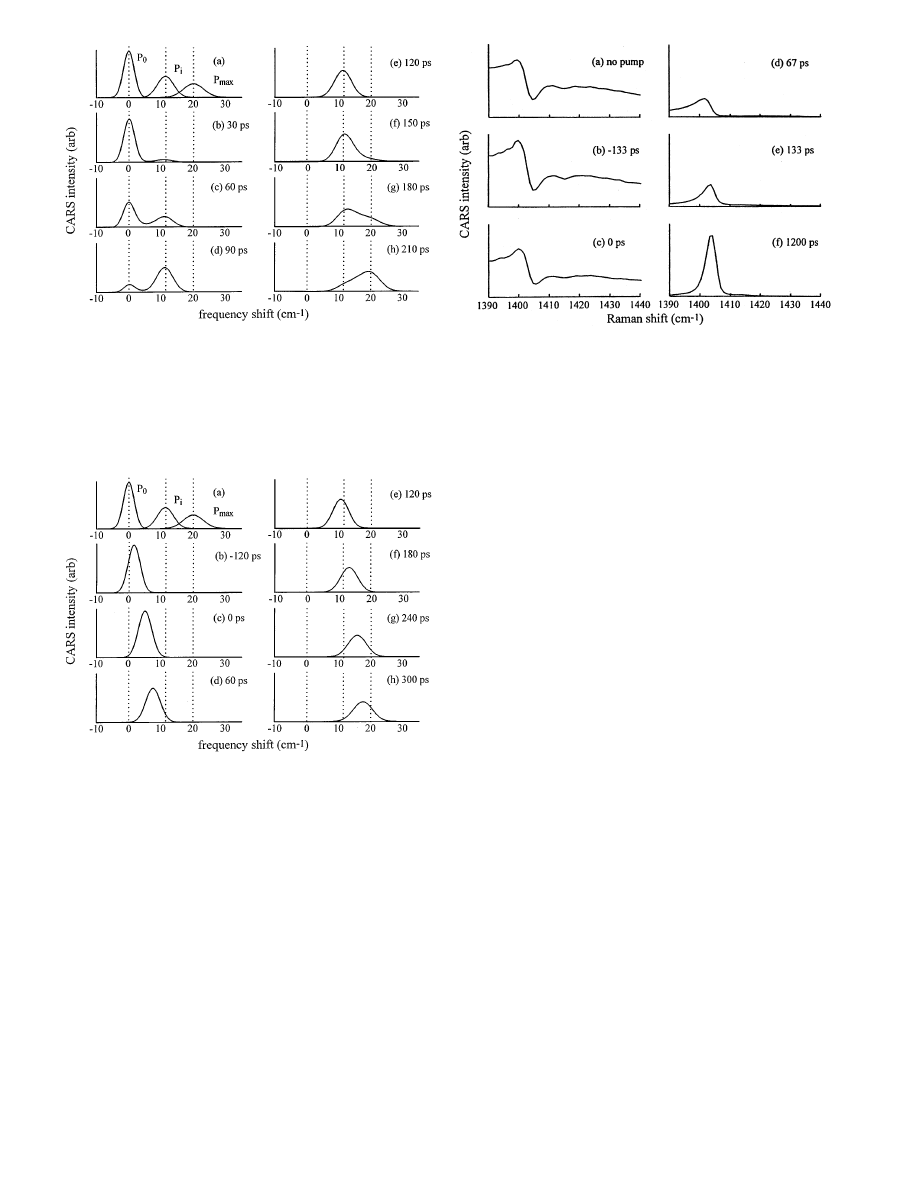
Fig. 5a–h. Simulations of CARS spectra of a crystal nanogauge where the
shock front risetime
t
r
= 10 ps and the shock transit time
t
tr
= 120 ps. Time
t = 0 denotes the arrival of the shock front midpoint at the nanogauge layer
surface. The reference spectra in (a) correspond to material at
P
0
, at the
incident shock pressure
P
i
and at the maximum shock pressure
P
max
. At
all times, the spectra are essentially superpositions of the three reference
spectra. By following the time variation in the peak areas, the velocity of
the shock through the nanogauge can be determined. At long times (not
shown) the spectrum becomes identical to the
P
max
spectrum in (a)
Fig. 6a–h. Simulations of CARS spectra of a crystal nanogauge where the
shock front risetime
t
r
= 400 ps and the shock transit time
t
tr
= 120 ps. Time
t = 0 denotes the arrival of the shock front midpoint at the nanogauge layer
surface. The reference spectra in (a) correspond to material at
P
0
, at the
incident shock pressure
P
i
and at the maximum shock pressure
P
max
. This
is a nearly reversible compression process. In a reversible compression, the
spectrum moves smoothly from zero peak shift to the maximum value. At
long times (not shown) the spectrum becomes identical to the
P
max
spectrum
in (a)
(slow). The simulation method has been discussed previ-
ously (Hambir 1996). In brief, the main assumptions and
simplifications are: (1) motivated by the Gaussian tempo-
ral envelope of the pump pulse, the pressure rise at the
shock front is taken to be an error function with risetime
t
r
; (2) time zero denotes the instant when the midpoint of
the shock front reaches the surface of the crystal nanogauge
layer; (3) the maximum shock load
P
max
= 5
.0 GPa, and the
incident shock pressure
P
i
= 2
.85 GPa; (4) the shock is as-
Fig. 7a–f. Experimental spectra of an anthracene target array during the
early stages of shock generation. Time
t = 0 denotes the arrival of the
150 ps duration near-IR pump pulse at the array. In (a–c) the spectrum
is a superposition of a broad component due to near-IR dye and a sharp
component due to the anthracene
ν
6
vibrational transition. After
∼ 1 ns
f, the dye layer has ablated away and the spectrum consists mainly of
anthracene
ν
6
with only a small contribution from the buffer layer polymer
and the glass substrate
sumed to travel across the crystal layer at a constant velocity
which is the average of the incident and reflected velocities,
which can be calculated from the anthracene Hugoniot to
be
U
s
= 4
.35 km/s; (5) the vibrational spectrum at any loca-
tion in the crystal is described by a Gaussian spectral line-
shape function
G
g
(
∆ν, ∆) where ∆ν and ∆ are the peak
location and width; (6) the peak shift depends solely on
P ;
(7) the peak width depends solely on
T ; (8) the pressure
and temperature dependence of the lineshape are modeled
by making the shift
∆ν and width ∆ both increase linearly
with pressure (this pressure dependence of
∆ is a simple
way of modeling the dependence of
∆ on T , since T de-
pends on
P ); (9) the CARS spectrum of the entire layer is
obtained by integrating the spectral contributions from ev-
ery location in the layer and squaring (Eesley 1981; Hambir
1996) the result; (10) as suggested by Fig. 8, the peak shift
at
P
max
is
∆ν
max
= 20 cm
−1
and the peak width ranges from
∆ = 4 cm
−1
at
P
0
to
∆
max
= 7
.5 cm
−1
at
P
max
.
The fast risetime simulation is shown in Fig. 5. In Fig. 5a,
three reference spectra are shown, corresponding to the
CARS spectrum of a crystal layer entirely at pressures
P
0
,
P
i
or
P
max
. As the peak shifts with higher pressure, it also
broadens due to higher temperature. Consequently the max-
imum peak amplitude decreases as the peak broadens. Since
the shock risetime
t
r
is so short (
t
r
= 10 ps in this simula-
tion), the spectrum at any time is essentially a superposition
of the three reference spectra. The shock front enters the
crystal layer at time
t = 0. During the 120 ps period it runs
through the crystal layer (Figs. 5b–e), the intensity of the
P
0
peak decreases and the intensity of the
P
i
peak increases.
Knowing the thickness of the layer, one can thus compute
the shock velocity from these spectra, keeping in mind the
spectral intensities are proportional to the square of the frac-
tion of the layer ahead of and behind the shock front (Eesley
1981; Hambir 1996). When the shock reflects from the glass
140
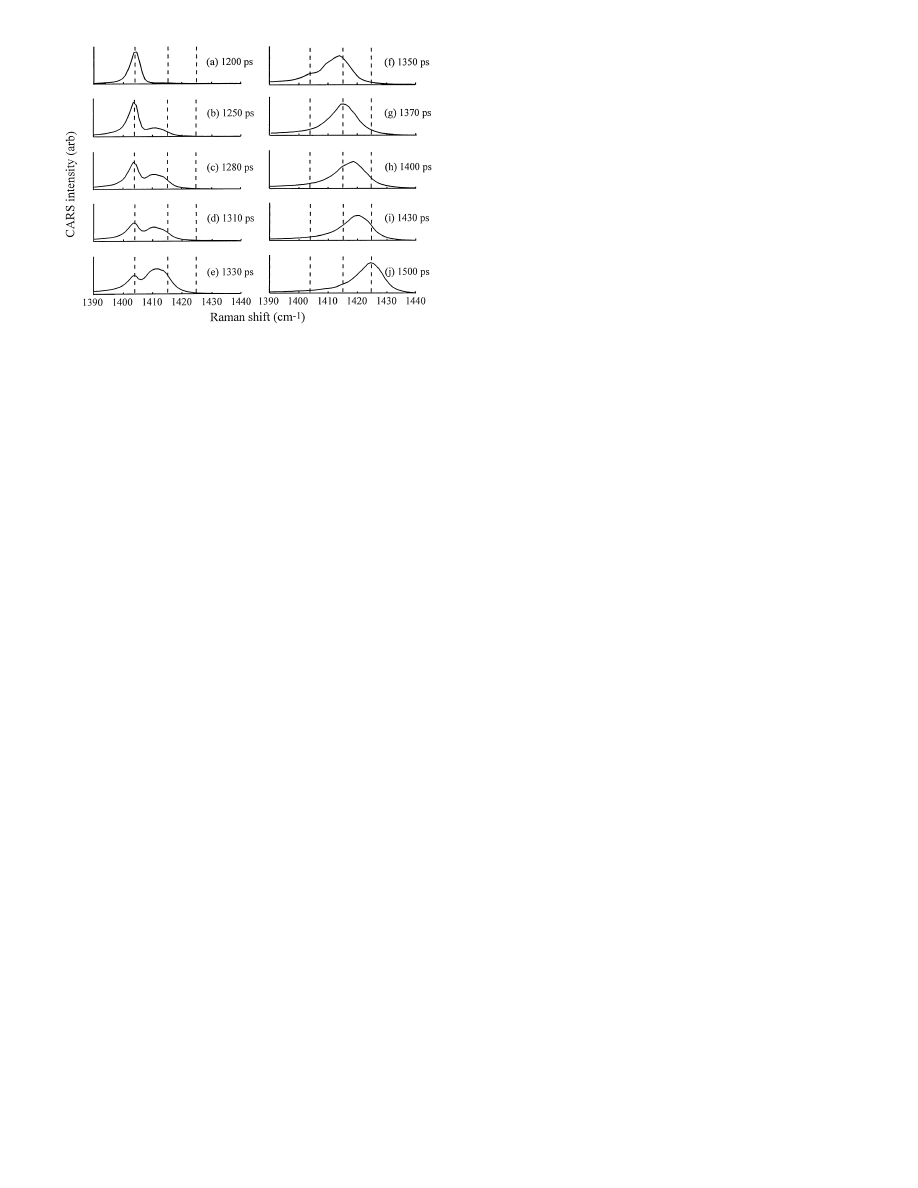
Fig. 8a–j. Experimental spectra of an anthracene target array as the shock
front passes through the anthracene layer. a Before shock. b At 1250 ps,
(time
t = 0 denotes the arrival of the pump pulse at the array) the first
traces of the
P
i
peak are seen, indicating the front has just entered the
anthracene layer. (b–f) As the front moves into the anthracene layer, the
intensity of the
P
0
peak (
∼ 1404 cm
−1
) declines and the intensity of the
P
i
peak (
∼ 1414 cm
−1
) grows. (g–j) As the reflected front moves back
through the layer, the intensity of the
P
i
peak declines and the
P
max
peak
(
∼ 1424.5 cm
−1
) grows. The round trip time through the 0
.5 µm thick
crystal layer (b–j) is
∼ 250 ps
substrate and returns through the layer, the spectra become
a superposition of
P
i
and
P
max
peaks. Because these peaks
represent shocks moving through higher temperature mate-
rial, the two peaks are broadened by the higher temperatures
and are in practice not very well resolved. After the reflected
shock front exits the crystal layer, the spectrum (not shown)
becomes identical to the
P
max
spectrum in Fig. 5a.
The slow risetime simulation is shown in Fig. 6. In
Fig. 6a, the three reference spectra corresponding to
P
0
,
P
i
and
P
max
are shown again. In this simulation, the shock front
risetime
t
r
= 400 ps, is considerably longer than the shock
transit time through the layer
t
tr
= 120 ps. Therefore the pres-
sure throughout the layer is at all times almost equal to the
external driving pressure. The compression process in this
case is nearly, but not quite (Hambir 1996), reversible. In a
reversible compression (or expansion) process, the pressure
is the same everywhere through the layer, and the pressure
rise in the layer tracks along with the pressure rise at the
shock front. Therefore the spectra in Fig. 6 are not really su-
perpositions of the three reference spectra
P
0
,
P
i
and
P
max
.
Instead the spectral peak moves smoothly and continuously
between
P
0
and
P
max
as the pressure in the crystal layer
slowly rises.
5 Experimental results
5.1 Shock generation layer
Figure 7 shows CARS spectra of the shock target array dur-
ing the early stages of shock generation. In the simulations,
t = 0 indicates arrival of the shock front at the nanogauge
layer. In the experiments, we do not know this shock arrival
time as accurately as we know the arrival of the peak of the
near-IR pump pulse at the target array, so when we refer
to experiments,
t = 0 denotes the arrival of the pump pulse.
(We will see below the pump pulse arrival at the target array
precedes the arrival of the shock front at the nanogauge by
∼ 1.25 ns). The spectrum of the array with no pump pulse
(Fig. 7a) or prior to the arrival of the pump pulse (Fig. 7b)
is mainly a superposition of a broad feature attributed to
electronic states of the near-IR dye (Hambir 1996), and a
narrower contribution from the anthracene
ν
6
Raman tran-
sition. These contributions are evidently out of phase, so
anthracene
ν
6
appears as a dip in the dye background. Once
the pump pulse begins to strongly heat the layer, the dye con-
tribution decreases (Figs. 7d,e). The decrease is attributed to
two causes. First, the dye may be decomposing or otherwise
reacting (e.g. electron transfer) with the other constituents
of the shock layer. Second, the shock layer is vaporizing,
and the vapor is leaving the target array at hypersonic ve-
locity (Hambir 1996). After about one ns (Fig. 7f), the shock
front has not yet reached the crystal nanogauge layer but the
spectral contribution of the near-IR dye layer is totally ab-
sent, indicating the shock generation layer has ablated away
(as in Fig. 4b). In other words we are using a disappearing
shock generation layer (Hambir 1996), which greatly aids
our ability to obtain high quality spectra.
5.2 Shock transit through the crystal nanogauge
In Fig. 8a, the shock has not yet quite reached the crystal
nanogauge layer. In Fig. 8b, at
t = 1250 ps, we see a small
contribution growing in from the peak representing pres-
sure
P
i
, indicating the shock front has just arrived at the
nanogauge. Since the buffer layer (Fig. 4a) is
∼ 5 µm thick,
this arrival time gives a rough estimate of the shock veloc-
ity through the buffer layer of
∼ 4 km/s (∼ 4 µm/ns). As
the shock front continues to move through the crystal layer,
the
P
0
peak intensity decreases and the
P
i
peak intensity
increases (Figs. 8b–f). By
t = 1370 ps, the P
0
peak has en-
tirely vanished, indicating the shock front has just reached
the glass substrate at the end of the nanogauge layer. Thus
the incident shock transit time through the 0
.5 µm thick layer
is 120
± 30 ps (the error bar is due in this case solely to the
spacing between adjacent time frames), which gives an es-
timate for the incident shock velocity of
U
s
= 4
.2 km/s. At
t = 1500 ps, the maximum shock load is attained, indicating
the shock front has just exited the nanogauge layer, which
gives a shock retransit time of
≈ 120 ps and a round trip
time of 2
t
tr
= 240 ps.
The experimental data (Fig. 8) is qualitatively quite simi-
lar to the simulations of the fast risetime case (Fig. 5), except
that the arrival time of the shock at the nanogauge layer (de-
noted
t = 0 in the simulations) is t ≈ 1250 ps in the experi-
ment. The most significant difference between the simulation
and the experiment is that the actual anthracene Raman line-
shape is not the simple Gaussian used in the simulations, but
instead has an asymmetric lineshape with an extended tail
to the red edge (e.g. Fig. 8a).
The unshocked anthracene spectral peak is centered at
1404 cm
−1
. The shock frequency shift for material behind
the incident shock front is
∆ν ≈ 10 cm
−1
(c.f. Fig. 8e,f), for
which Fig. 2 gives an incident shock pressure
P
i
= 2
.8 GPa.
141
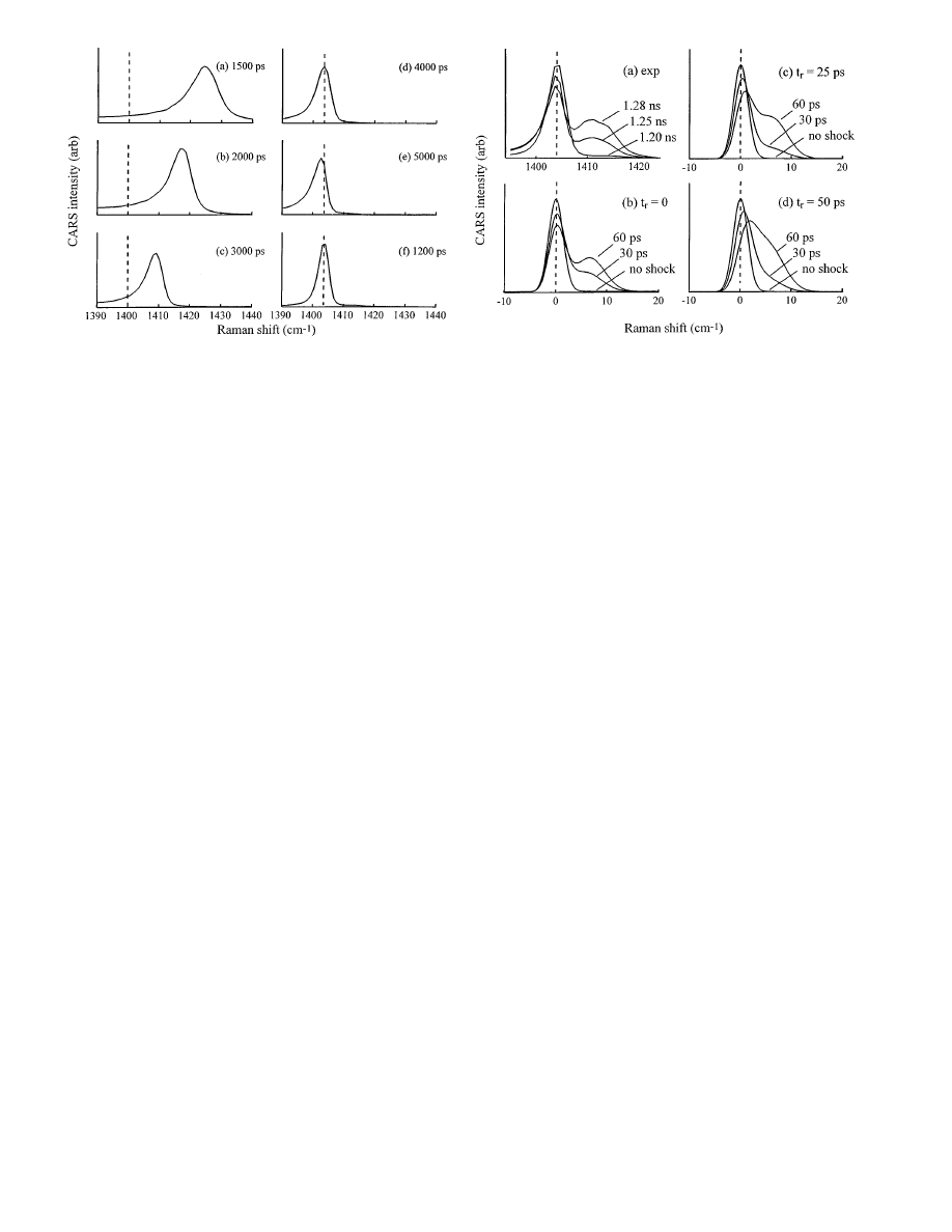
Fig. 9a–f. Experimental spectra of an anthracene target array during shock
unloading. During this reversible process, the peak moves smoothly from
its maximum blueshift (
∼ 20.5 cm
−1
) back toward zero blueshift. After
unloading (e) the peak is somewhat broader and slightly redshifted relative
to the unshocked spectrum (f). The temperature increase in the anthracene
crystal layer after the cycle of irreversible shock loading and reversible
unloading is found from the redshift and width of the spectrum in (e) to be
∆T
irr
= 70
± 20 deg
The maximum frequency shift is
∆ν ≈ 20.5 cm
−1
(c.f.
Fig. 8g), for which Fig. 2 gives a maximum shock pres-
sure
P
max
= 4
.8 GPa. Thus the measured ratio between the
incident shock pressure (2.8 GPa) and the reflected shock
pressure (2.0 GPa),
P
r
/P
i
≈ 0.7. That is, within experimen-
tal error, equal to the value
P
r
/P
i
= 0
.75 given by Eq. 5
for literature values of
Z
glass
/Z
anth
. According to Fig. 3b,
the anthracene temperature behind the incident shock front
T
i
≈ 200
◦
C, and behind the reflected shock
T
max
≈ 380
◦
C.
The accuracy of this temperature determination is discussed
in more detail in Sect. 6.3.
5.3 Shock unloading
In contrast to the shock loading process, shock unloading
occurs via rarefaction wave propagation, and it is intrinsi-
cally a reversible process (Zel’dovich 1966). Figure 9 shows
spectra during the unloading process. At
t = 1500 ps, the
crystal layer is under its maximum load. The maximum
loading period lasts for a few hundred ps. Unloading oc-
curs over an
∼ 3000 ps time period. Figure 9 shows the
time dependent spectra during unloading are characteristic
of a reversible process (c.f. Fig. 6). That is to say the spec-
tral peak moves smoothly and continuously from the maxi-
mum blueshift back toward zero frequency shift. A multiple
peak spectrum such as seen during irreversible shock loading
(Fig. 8) is not seen, because the pressure during unloading
is approximately equal everywhere within the crystal layer.
5.4 Irreversible temperature increase
Figures 9e and f permit us to compare the spectrum of the
crystal layer before shock (Fig. 9f) and immediately after
Fig. 10. a Shock spectra of an anthracene target array before shock (1.20 ns),
∼ 30 ps after the shock front has entered the nanogauge layer (1.25 ns)
and
∼ 60 ps after the front entered the layer (1.28 ns). The P
0
peak at
∼ 1404 cm
−1
shows no discernible blueshift. (b–d) Simulations of the
spectrum at the indicated values of the shock front risetime
t
r
. In the sim-
ulations,
t = 0 indicates the arrival of the front at the nanogauge. That
corresponds to
∼ 1.25 ns in the experiments. The blueshift of the P
0
peak
increases with increasing
t
r
. Comparison of the data a to the simulated
spectra show the experimental shock front risetime
t
r
< 25 ps
the cycle of irreversible shock compression and reversible
unloading back to ambient pressure
P
0
(Fig. 9e). After the
loading and unloading process, the spectrum is broader and
slightly redshifted compared to the ambient spectrum before
shock. The width has increased from 3.9 to 5
.0 cm
−1
and
the redshift is 1
.5 cm
−1
. From our prior study of anthracene
temperature dependence (Hambir 1996), these features are
known to be characteristic of hot anthracene at ambient pres-
sure. The width increase is due to an increase in the rates
of vibrational dephasing processes and the redshift is due to
a lower density caused by thermal expansion. We can esti-
mate
∆T
irr
by comparing the width and shift to the values
obtained by CARS spectroscopy of anthracene in a heated
optical cell (Hambir 1996). Both the shift and width are con-
sistent with a value
∆T
irr
= 70
± 20 deg. Since the entire
process of compression and unloading occurred in
< 4 ns,
both processes were adiabatic. There simply was not enough
time for any heat loss from the crystal nanogauge layer to its
surroundings. Using the experimental measurement of
∆T
irr
to determine the entropy increase across the shock front, and
to assess the accuracy of our shock temperature determina-
tions is discussed below in Sect. 6.2.
5.5 Shock front risetime
The spectra in Fig. 8 allow us to estimate the shock front
risetime in the crystal nanogauge layer. Figs. 10b–d are sim-
ulations of spectra at early times, just before the front has
entered the nanogauge layer (denoted “no shock”) and when
it is 1/4 and 1/2 of the way through the layer (30 and 60 ps),
using spectral shift and width parameters obtained from the
experimental data in Fig. 8. Initially there is only a
P
0
peak
at
∆ν = 0, but as the shock enters the crystal layer, a new
peak representing pressure
P
i
grows in. If we look only at
142
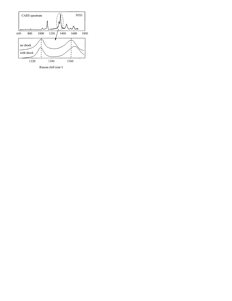
Fig. 11. (top) CARS spectra of a nanogauge composed of the crystalline
insensitive high explosive NTO. The peak intensities were not corrected for
the apparatus response. (bottom) Blow up of the spectrum near 1350 cm
−1
showing two nearby NTO vibrational transitions. At maximum shock load,
the peaks shift in opposite directions
the
P
0
peak, Fig. 10 shows this peak blueshifts slightly when
a finite risetime shock front passes through the crystal layer,
and the magnitude of this blueshift increases with increas-
ing risetime
t
r
. When the shock front rises instantaneously,
the nanogauge layer consists solely of material at
P
0
and
P
i
, there are two peaks at
P
0
and
P
i
, and the
P
0
peak does
not blueshift at all. For a finite risetime shock front, there
will be some material at pressures intermediate between
P
0
and
P
i
. The longer this risetime, the larger is the region of
intermediate pressures. The effect of the intermediate pres-
sure region is to cause the
P
0
transition to blueshift a bit,
and the
P
i
transition to redshift a bit. In addition, the spec-
tral region between the two peaks in Fig. 10 begins to fill
in as
t
r
increases, but we cannot reliably use this feature
of the simulations to determine
t
r
because the lineshapes in
the simulations do not exactly match the experimental line-
shapes.
When we look at the experimental data (Fig. 10a), we
see the
P
0
transition shows no discernible blueshift as the
shock moves through the nanogauge layer. That indicates
an almost total absence of material at pressures between
P
0
and
P
i
. Thus the shock front in the crystal nanogauge layer
has a very step rise. Comparing the experimental data with
the simulations indicate the shock front risetime
t
r
< 25 ps.
Notice this method will not work well with a very thick
nanogauge layer, because CARS gives the spectrum of the
entire layer, and in a thick layer, the fraction of material at
the shock front will be very small.
5.6 Energetic materials
Figure 11 shows ps CARS data obtained using a shock tar-
get array assembly where the nanogauge was a thin poly-
crystalline layer of the insensitive energetic material NTO.
The top panel shows the CARS spectrum of a thin layer of
NTO. That spectrum was obtained using 4 different dyes in
the broadband dye laser, and splicing the 4 spectra (Hare
1995b). The relative intensities were not corrected in the
splicing procedure. In the lower panel, an expanded view of
the most intense peaks in the NTO spectrum is shown with-
out shock, and at the maximum shock loading condition.
The two nearby peaks are nicely resolved. These two vi-
brational transitions respond quite differently to shock. The
higher frequency transition shows a larger blueshift and the
lower energy transition shows a smaller redshift under shock
loading. The extent of shock loading seen here is somewhat
less than in anthracene, because the shock generation layer
was an older design, and NTO has a somewhat greater shock
impedance than the PMMA buffer layer.
6 Discussion
Our new technique generates ultrahigh time resolution vi-
brational spectra, which allows us to probe the fast response
of molecular materials to shock waves with unprecedented
detail. With this technique we can study a wide variety of
materials, including polycrystalline materials, which are of-
ten problematic (Trott 1988), since polycrystalline materials
scatter light. In these initial demonstration experiments, we
have obtained a time resolution (tens of ps) which is about
three orders of magnitude better than the prior state of the
art in shock wave vibrational spectroscopy. In addition, we
have developed a novel method of measuring very short
(
< 25 ps) shock front risetimes in solids based on Raman
lineshape analysis. We now can monitor the subnanosecond
propagation and reflection of the shock front in real time,
which permits direct measurements of the velocity. The high
resolution of our CARS spectra allows for spectroscopic de-
termination of
T and P behind the shock front. The magni-
tude of irreversible heating induced by shock compression
can also be measured by exploiting the nanosecond cycle of
shock loading and unloading.
While we have demonstrated the versatility of our ap-
proach, we have not yet measured physical quantities with
the high precision associated with more conventional, well-
developed shock technologies. We have considerable opti-
mism for our ability to greatly improve this precision, since
shock target arrays are easily fabricated, and the shock gen-
eration system operates reproducibly at an extremely high
repetition rate of
∼ 100 shocks/s and > 10
6
shocks/day.
In the rest of this section, we discuss briefly how these
techniques can be used to measure the important properties
of shock waves in solids. We also discuss some possibilities
for future work based on our unique ability to investigate the
very fast response of microscopic targets to shock waves.
6.1 Measuring the Hugoniot
Hugoniot is a term used to describe a series of relationships
involving the variables
U
s
,
U
p
,
∆V and P (Marsh 1980).
In our spectroscopy experiments, it is most convenient to
measure the quantities
U
s
and a spectral shift
∆ν which can
be used to find
∆V or P . A Hugoniot can then be obtained
by varying
P , which is easily accomplished by varying the
intensity of the pump laser pulses.
In anthracene, we have a reasonable way of determin-
ing
∆V and P from spectral shifts, since the Hugoniot and
isothermal compression curve was available in the literature.
We will not necessarily know the relationship between the

143
spectrum and
P for an arbitrary unknown material. To over-
come this difficulty, we propose fabricating a target array
in which the shock pressure is determined by first passing
the shock front through a standard nanogauge layer such as
anthracene, before the front enters the unknown layer. We
could account for the shock reflection due to impedance mis-
match at the unknown layer by measuring the pressure of
the reflected shock in the standard layer.
The unique features of this proposed Hugoniot determi-
nation method are that physical properties are determined
on the sub nanosecond time scale, and the quantity of mate-
rial needed is of mg order. The high speed of this measure-
ment could potentially introduce qualitatively new ideas into
Hugoniot measurements. In energetic material studies, it is
often desired to know the Hugoniot of the unreacted mate-
rial, and with our method we should be able to investigate
many energetic materials before they have had time to react
significantly. Carrying this idea a bit further, we might con-
sider investigating the Hugoniot of materials in metastable
states which persist for at least a few hundred ps. In our
reflection geometry, we can investigate the Hugoniot of ma-
terials which have been previously shocked to pressure
P
i
,
by studying the propagation of the reflected shock through
previously shocked material. Other examples which come
immediately to mind are partially reacted explosives, or ma-
terials in electronically excited states.
6.2 Entropy increase
It is difficult with conventional methods to determine the
entropy increase across the shock front. In our experiments,
the crystal nanogauge layer initially at (
T
0
, V
0
) is subjected
to the following thermodynamic cycle:
(
P
0
, T
0
, V
0
)
shock (irrev)
−→ (P
max
, T
max
, V
min
)
unloading (rev)
−→
(
P
0
, T
0
+
∆T
irr
, [1 + α∆T
irr
]
V
0
)
slow cooling
−→ (P
0
, T
0
, V
0
)
,
where
α is the coefficient of volume thermal expansion. The
total entropy change of the crystal nanogauge layer in this
cycle
∆S
cycle
= 0, and the entropy change for the reversible
unloading step
∆S
rev
= 0 as well, so the entropy decrease
of the layer in the third slow cooling step is exactly equal
in magnitude to the entropy increase across the shock front.
As described in Sect. 5.4, the value of
∆T
irr
can be deter-
mined by CARS spectroscopy immediately after the crystal
nanogauge layer unloads. The entropy increase across the
shock front is given in terms of
∆T
irr
as (Zel’dovich 1966),
∆S =
T
0
+
∆T
irr
Z
T
0
C
p
T
dT .
(6)
The quantity
∆S in Eq. 6 can be measured with extremely
high accuracy using conventional techniques of constant
pressure differential scanning calorimetry. In our experi-
ment, where
∆T
irr
= 70
± 20 deg, we find ∆S = 44 ±
10 J/mol/deg.
6.3 Equation of state
Equation of state (EOS) describes a series of relationships
between the temperature
T and the pressure or volume
(Zel’dovich 1966). In our previous work (Hambir 1996),
we discussed the possibility of determining the higher tem-
perature behind the shock front from CARS spectra of the
shocked hot material. The difficulty with that approach is
knowing how the spectrum depends on
T and P for quite
large values of
T and P behind the shock front. In some
cases, it is possible to obtain calibration data by measuring
the CARS spectrum of sample material in a heated diamond
anvil pressure apparatus. However such determinations be-
come problematic if the sample material decomposes at high
temperatures.
Here we describe another way of determining the EOS,
which relies primarily on calibration data already obtained
(Hambir 1996) under mild conditions of
T and P . First
the value of
∆T
irr
is determined spectroscopically as de-
scribed above. Notice that
∆T
irr
is determined by comparing
a CARS spectrum after shock unloading, when the pressure
is
P
0
, to calibration spectra at
P
0
easily obtained by rela-
tively gentle heating of the sample at ambient pressure. It
can be shown for a shock which takes a known path (e.g.
a single-stage shock), that the value of the Gr¨uneisen pa-
rameter
Γ can be determined if ∆T
irr
is known (Tokmakoff
1993). Combining such a determination of
Γ with a Hugo-
niot generates an EOS, which is accurate provided
Γ does
not vary much with
T or V . A more accurate EOS could
be generated, to account the temperature or volume depen-
dence of
Γ , by measuring ∆T
irr
at many different values of
the shock pressure.
To illustrate how this might work, consider the tem-
perature calculation in Fig. 3b. This calculation assumed a
value of
Γ = 4, based on low temperature measurements
of naphthalene (Kitaigorodskii, 1973). For a single-stage
4.8 GPa shock, Fig. 3b predicts a value of
∆T
irr
= 60 deg.
That is, of course, an upper limit to
∆T
irr
, since the ac-
tual experiment is a two-stage shock. Since the experimental
value was
∆T
irr
= 70 deg, that indicates our initial guess of
Γ = 4 was somewhat too low. That is not surprising, be-
cause anthracene differs from naphthalene in being a larger,
more flexible molecule with more lower frequency vibra-
tions. Having more lower frequency vibrations tends to in-
crease the value of
Γ (Tokmakoff 1993). Doing a more de-
tailed study of the dependence of
∆T
irr
on shock pressure
would allow us to further improve the anthracene EOS. In
the absence of these detailed measurements, we can still
conclude at the present time that the temperature values in
Fig. 3b and the values given in Sect. 5.2 are evidently a bit
too low.
6.4 Shock risetime
The shock front risetime depends on the details of dissipative
processes occurring at the front (Graham 1993; Zel’dovich
1966). Measurements of the risetime provide deep insight
into the fundamental mechanisms of shock compression. In
fluids, the risetime is ordinarily thought to be quite fast (Har-
ris 1982; Leung 1985). In molecular dynamics simulations

144
of shocks in solids, shock fronts only a few molecules wide
have been seen (Holian 1980). But in studies of shock propa-
gation through real solid materials of finite dimensions (typ-
ically mm or more), shock fronts develop a complicated
structure which occurs on the 10
−9
–10
−6
s time scale (Gra-
ham 1993). Our measurement shows for the first time that a
shock front with an extremely short risetime of
< 25 ps (the
width of the shock front is less than 100 nm) can propagate
through a dense polycrystalline material, at least over a quite
short (0
.5 µm) length scale.
6.5 Future directions
The shock target array technique is extremely flexible. In our
laboratory, we have already constructed and investigated ar-
rays with crystal nanogauges of anthracene and naphthalene,
and energetic materials RDX, PETN, NTO and TATB. Thus
there appear to be no fundamental reasons our studies can-
not be extended to a wide variety of interesting molecular
materials.
By fabricating more sophisticated layered structures, we
can exert more control over the shock process. For exam-
ple, we could eliminate the complications of the two-stage
shock by placing the crystal nanogauge layer between two
impedance matched layers. That could be accomplished by
replacing the glass window with a Plexiglas window, or by
adding an impedance-matched polymer layer between the
crystal layer and the glass.
Another possibility involves structures with more than
a single nanogauge layer. With vibrational spectroscopy it
is possible to monitor well-resolved vibrational transitions
of several materials simultaneously. For example, imagine a
target array consisting of an anthracene nanogauge followed
by a thin layer of unknown material against a glass window.
The shock would pass first through the anthracene, allowing
its velocity, pressure and risetime to be determined. Then
the shock would do a round trip through the unknown ma-
terial and subsequently return back through the anthracene,
where its velocity, pressure and risetime could again be mea-
sured. One could thus investigate how passing through the
unknown material affected these properties. If the unknown
is an explosive or otherwise reactive material, energy re-
leased during shock induced initiation could increase the
shock velocity. If the unknown was porous or had an oth-
erwise complicated mechanical response, that effect on the
risetime could be investigated. Clearly there are many pos-
sibilities for future work in these areas.
It is greatly desired to determine the first steps in shock
wave initiation of energetic materials. Vibrational spec-
troscopy is the most suitable method of studying fast, multi-
component chemical reactions in situ. We have not yet seen
any initiation chemistry, because the duration of our shock
waves is quite short and we have so far studied only in-
sensitive materials. The duration of shock loading could be
increased by using thicker shock generation layers, which
would have to be pumped by more powerful lasers than we
currently have available, but more sensitive energetic mate-
rials can be studied in the future.
Acknowledgements. This research was supported by National Science Foun-
dation grant DMR 94-04806, US Army Research Office contract DAAH04-
96-1-0038, and Air Force Office of Scientific Research contract F49620-94-
1-0108. Measurements of layer thicknesses were carried out in the Center
for Microanalysis of Materials, University of Illinois, which is supported
by the US Department of Energy under grant DEFG02-91-ER45439. We
acknowledge with gratitude our collaborators in static high pressure cal-
ibration studies, from Prof. Eric Chronister’s group at the University of
California, Riverside.
References
Abasbegovic N, Vukotic N, Colombo L (1964) Raman spectrum of an-
thracene. J. Chem. Phys. 41:2575
Beardall DJ, Botcher TR, Wight CA (1996) Explosive thermal decomposi-
tion mechanism of NTO. In: Brill TB, Russell TP, Tao WC, Wardle;
RB (eds) Decomposition, combustion, and detonation chemistry of en-
ergetic materials, Mat. Res. Soc. Proc. 418, Materials Research Society,
Pittsburgh, pp 379–384
Cagnoux J, Chartagnac P, Hereil P, Perez M (1987) Lagrangian analysis.
Modern tool of the dynamics of solids. Ann. Phys. Fr. 12:451
Cottet F, Romain JP (1982) Formation and decay of laser-generated shock
waves, Phys. Rev. A 25:576
Domalski ES, Evans WH, Hearing ED (1984) Heat capacities and entropies
of organic compounds in the condensed phase, J. Phys. Chem. Ref. Dat.
13, suppl. No. 1
Dlott DD (1988) Dynamics of Molecular Crystal Vibrations. In: Yen W (ed)
Laser Spectroscopy of Solids II. Springer Verlag, Berlin, pp 167–200
Eesley GL (1981) Coherent Raman Spectroscopy, Pergamon, Oxford
Graham RA (1993) Solids under high-pressure shock compression. Me-
chanics, physics and chemistry. Springer-Verlag, New York
Hambir SA, Franken J, Hare DE, Chronister EL, Baer BJ, Dlott DD (1996)
Ultrahigh time resolution vibrational spectroscopy of shocked molec-
ular solids. J. Appl. Phys. (submitted 10/96)
Hare DE, Dlott DD (1994) Picosecond coherent Raman study of solid-state
chemical reactions during laser polymer ablation. Appl. Phys. Lett.
64:715
Hare DE, Franken J, Dlott DD (1995a) Coherent Raman measurements of
polymer thin film pressure and temperature during picosecond laser
ablation. J. Appl. Phys. 77:5950
Hare DE, Franken J, Dlott DD (1995b) A new method for studying picosec-
ond dynamics of shocked solids: application to crystalline energetic
materials Chem. Phys. Lett. 244:224
Harris P, Presles H-N (1982) The shock induced electrical polarization of
water. J. Chem. Phys. 77:5157
Hess LA, Prasad PN (1980) Vibrational dephasing in organic solids: tem-
perature dependence of a Raman active localized internal mode of
naphthalene. J. Chem. Phys. 72:573
Holian BL, Hoover WG, Moran B, Straub GK (1980) Shock-wave structure
via nonequilibrium molecular dynamics and Navier-Stokes continuum
mechanics. Phys. Rev. A 22:2798
Holmes NC, Nellis WJ, Graham WB, Walrafen GE, (1985) Spontaneous
Raman scattering from shocked water. Phys. Rev. Lett. 55:2433
Kitaigorodskii AI (1973) Molecular Crystals and Molecules, Academic,
New York
Lee IYS, Hill JR, Dlott DD (1994) Ultrafast microscopy of shock waves
using a shock target array with an optical nanogauge. J. Appl. Phys.
75:4975
Lee IYS, Hill JR, Suzuki H, Baer BJ, Chronister EL, Dlott DD (1995)
Molecular dynamics observed 60 picoseconds behind a solid-state
shock front. J. Chem. Phys 103:8313
Leung KP, Doukas AG, Jones PH, Papadimitriou D, Alfano RR, Harris P
(1985) Shock-front-stimulated optical scattering in water. Phys. Rev.
B 31:8329
Marsh SP (1980) LASL Shock Hugoniot Data. University of California,
Berkeley
Moore DS, Schmidt SC, Shaw MS, Johnson JD (1991) Coherent anti-Stokes
Raman spectroscopy of shock-compressed liquid nitrogen. J. Chem.
Phys. 90:1368

145
Nicol M, Vernon M, Woo JT (1975) Raman spectra and defect fluores-
cence of anthracene and naphthalene crystals at high pressures and
low temperatures, J. Chem. Phys. 63:1992
Pangilinan GM, Gupta YM (1994) Time-resolved Raman measurements in
nitromethane shocked to 140 kbar. J. Phys. Chem. 98:4522
Schmidt SC, Moore DS, Shaner, JW (1983) Raman spectroscopies in shock-
compressed materials. In: Asay JR, Graham RA, Straub GK (eds)
Shock waves in condensed matter - 1983, Elsevier, Amsterdam, 1984,
pp 293–302
Schmidt SC, Moore DS, Shaw MS (1987) Vibrational spectroscopy of fluid
N
2
up to 34 GPa and 4400 K. Phys Rev. B 35:493
Schmidt SC, Schiferl D, Zinn AS, Ragan DD, Moore DS (1991) Calibration
of the nitrogen vibron pressure scale for use at high temperatures and
pressures. J. Appl. Phys. 69:2793
Tokmakoff A, Fayer MD, Dlott DD (1993) Chemical reaction initiation and
hot spot formation in shocked energetic molecular materials. J. Phys.
Chem. 97:1902
Trott WM, Renlund AM (1988) Single-pulse Raman scattering study of
triaminotrinitro-benzene under shock compression. J. Phys. Chem.
92:5921
Vaidya SN, Kennedy GC (1971) Compressibility of 18 organic solids to 45
kbar. J. Chem. Phys. 55:987
Warnes RH (1970) Shock wave compression of three polynuclear aromatic
compounds. J. Chem. Phys. 53:1088
Yoo CS, Gupta YM, Horn PD (1989) Pressure-induced resonance Raman
effect in shocked carbon disulfide. Chem. Phys. Lett. 159:178
Yoo CS, Holmes NC, Souers PC (1996) Detonation in shocked homoge-
neous high explosives. In: Brill TB, Russell TP, Tao WC, Wardle RB
(eds) Decomposition, combustion, and detonation chemistry of ener-
getic materials, Mat. Res. Soc. Proc. 418, Materials Research Society,
Pittsburgh, pp 397–406
Zel’dovich YB, Raiser YP (1966) Physics of shock waves and high-
temperature hydrodynamic phenomena, Academic, New York
Wyszukiwarka
Podobne podstrony:
Proton Magnetic Resonance Spectroscopy of the Medial Prefrontal Cortex in Patients With Deficit Schi
Freedom in the United States Analysis of the First Amendme
Military men figured prominently in the leadership of the first English
ALASTAIR GALBRAITH MATT DE GENARRO Long Wires in Dark Museums Vol 2 CD (Table Of The Elements) XER1
Microsoft Word Spectre of the Black Rose Sam
Chapman The Interpretation of Certain Verses of the First Chapter of Genesis in the Light of Paleont
Spectral intensity measurement for soot formation of benzene behind reflected shock waves
The evolution of brain waves in altered states
MR spectroscopic studies of the brain in psychiatric disorders
Black Holes & Gravitational Waves in String Cosmology(1998)
The Spectre of Shakespeare in Rosencrantz and Guildenstern are Dead
autismo prevalence of disorders of the autism spectrum in a population cohort of children in south t
Spectrum of ATM Gene Mutations in a Hospital based Series of Unselected Breast Cancer Patients
WD Gann on The Law of Vibration Prepared in Honor of the 9 th Anniversary of the Foundung of Gann S
Possibility of acceleration of the threshold processes for multi component gas in the front of a sho
Jacobsson G A Rare Variant of the Name of Smolensk in Old Russian 1964
Functional improvements desired by patients before and in the first year after total hip arthroplast
Congressional Research Services, 'NATO in Afghanistan, A Test of the Transatlantic Alliance', July 2
The?uses of the Showa Restoration in Japan
więcej podobnych podstron