78
Home Power #21 • February / March 1991
The Basics- Site Survey
could be described as windy, based on these observations, then
consider an alternative to wind power.
Using a Recording Anemometer
If you feel your site is windy, and you are serious about installing a
wind turbine, then install a recording anemometer. In some areas,
a check with the local weather station might be sufficient to
determine average wind speeds. Wind data from airports is not
very applicable to wind power sites because airports are
intentionally located at sites with minimum winds. Don't consider
wind power without a thorough measurement of the wind speed at
your specific location. In most cases, four months should be the
minimum recording interval and one year is preferred. If you are
going to spend a lot of hard earned money on a wind system, this
extra eight months could mean the difference between a good
investment and a bad one.
Proper Tower Placement
Although a recording anemometer is a very accurate instrument, its
output information will be accurate at a specific location. In areas
of rolling hills or tree cover, the wind speeds can vary 30% or more
between sites only 100 feet apart. The location of an anemometer
on a specific site, as well as height above the ground and any
obstruction, is critical to recording the highest winds available. On
level land with no nearby obstacles, a 40 foot tower should be the
minimum height for your anemometer or turbine. It is essential to
measure wind speed at the actual height you plan on installing your
turbine. Obstacles or short towers are only robbing you of power. If
you are considering placing your turbine on a hill to gain wind
speed, place the turbine high enough on the hill to enter the
smooth undisturbed wind stream.
Installing a wind turbine is not a matter of simply erecting a tower
and putting a generator on top. Only through accurate wind speed
data on your particular site can you hope to install a wind system
that is capable of supplying the power you need.
Larry Elliott
Specifying Wind Systems
Editor's Note: The following wind survey concept arose between
Mick and I during a phone conversation. It bears so much
relevance that I have included it here. RP.
Alternatives to a Recording Anemometer
Average Wind Speed
While average wind speed is meaningful, there are other wind
parameters that are just as meaningful. Other wind parameters
worth knowing are maximum wind speed, number of days (hours)
between winds of greater than 10 mph. Number of consecutive
days (hours) where the wind is in excess of 10 mph, and the times
of year where the either wind or not wind periods occur. All this
data is not available from garden variety recording anemometers.
A recording anemometer that will take all the data mentioned
above will cost a bundle. Such anemometers are more computer
than wind sensor and cost between $2,000 and $4,000. I offer the
following alternative.
Install a Small Wind Machine
For the cost of a detailed recording anemometer, you can install a
working small wind machine. Consider that a Whisper 1000 or a
Windseeker can be installed at about the same cost as a
sophisticated recording anemometer. With the addition of an
accumulative Ampere-hour meter (about $200), this setup not only
provides real and hard data about wind powered electric
generation, but also supplies power at the same time.
What if I don't really have a site suitable for wind?
It is much easier to sell a working wind machine than a
sophisticated recording anemometer. If your site turns out not to
have appreciable wind power potential, you can more easily get
your money out of a wind machine. If your wind site has potential,
then you have a great head start on your wind electric system.
Access
Mick Sagrillo, Lake Michigan Wind and Sun, 3971 E. Bluebird
Road, Forestville, WI 54213 • 414-837-2267.
Homebrew
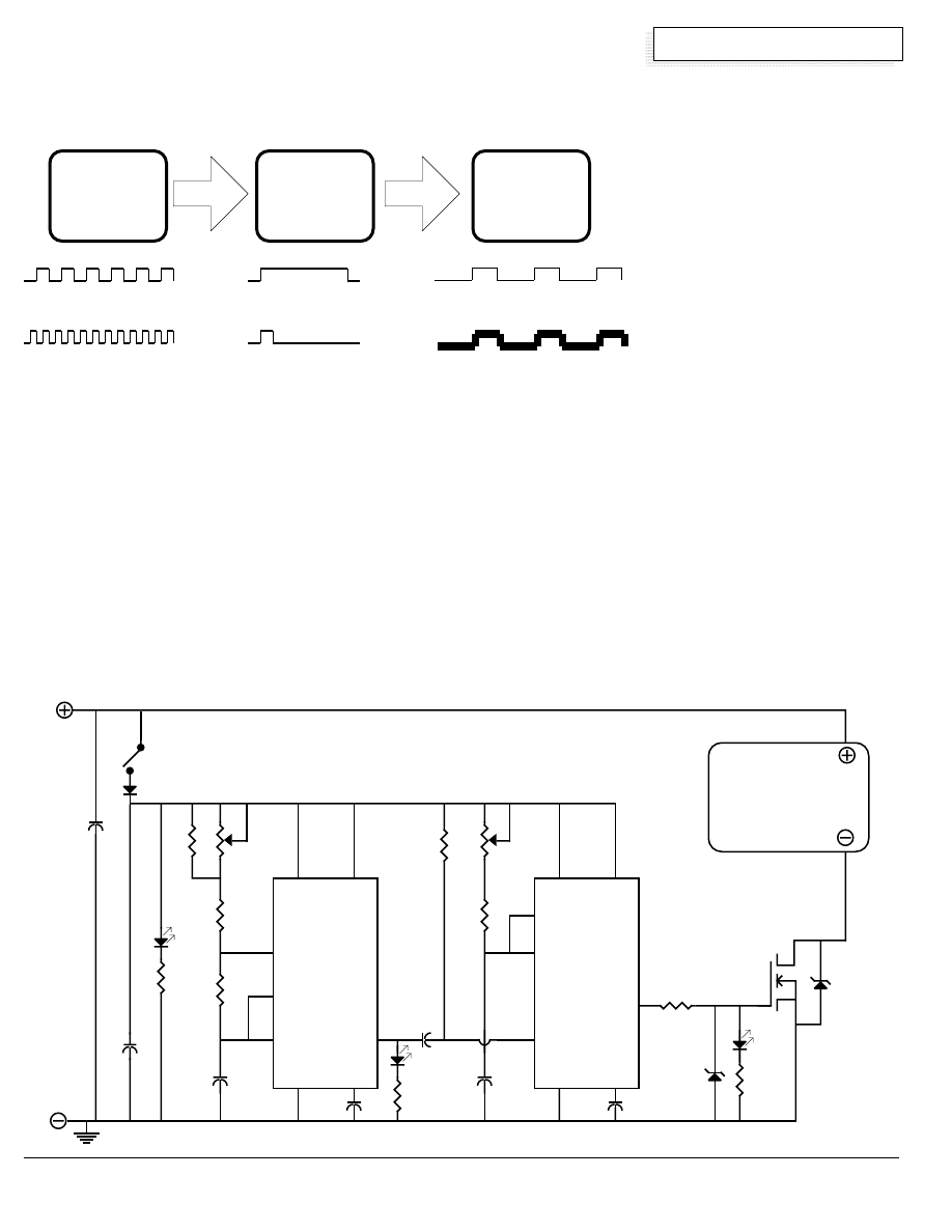
Build a Time Machine
Richard Perez
This electronic device is a time machine. It makes precisely timed
pulses of electricity. The pulses can occur as often as you wish
and last for as long as you wish. Some of the many applications
for this device are: a super efficient 12 VDC motor speed
controller, an high efficiency electronic rheostat for DC power
control, and an electric fence charger that keeps pesky critters
where you want them. All of this and more from precisely timed
electronic switching!
A Time Machine?
You bet. This circuit uses two NE555 electronic timers to make
custom tailored pulses of electricity. The first NE555 timer, U1, is
operated astable as an oscillator, or in techie lingo– a multivibrator,
or in nerd terms– a flip-flop. U1 determines how often the pulses
occur. There could be one pulse every ten seconds or thousands
of pulses per second. The second NE555 timer, U2, determines
the amount of time that the pulse spends ON, or in other words,
the duration of the pulse. U2 is operated as a slave to U1. U2
only emits a pulse when U1 says to do so. U2 is operated in
monostable mode, as a "one-shot" multivibrator. The pulse
produced by U2 may have a duration of seconds, or may have a
period as short as microseconds. The resulting pulse train is fed
to a power amplifier that switches the load. And that's the whole
point of this device, chopping electricity into pulses in order to
control power.
79
Home Power #21 • February / March 1991
Homebrew
So who needs pulses?
Using pulses of electricity can solve many power control problems
in 12 VDC systems. For example, consider controlling the speed
of an electric motor. The most common method of controlling 12
VDC electric motors is to insert a resistor in series with the motor.
This indeed limits the motor's speed by reducing the amount of
power available to the motor. It also wastes gobs of power in the
resistor.
Another way of controlling the motor is to rapidly switch its power
ON and OFF. The major advantage switching is a vast reduction
in power consumption. When the electronic switch is OFF, then
virtually no power is used. In this switching scenario, the amount
of power the motor uses is proportional to its speed. The slower
the motor rotates, the less power it uses. Compare this to the
resistor power control method where power consumption remains
relatively constant regardless of
motor speed.
Notes on the Time Machine
C1 is the timing capacitor for U1, the
astable multivibrator. Increasing the
value (amount of capacitance) of C1
will decrease the frequency of the
pulses that the Time Machine
produces. C2 is the timing capacitor
for U2, the monostable multivibrator.
Increasing the capacitance of C2 will
result in pulses of longer duration.
The table below shows the values for
C1 and C2 and the resulting timing
parameters for this circuit. Since the
NE555 uses a resistor/capacitor
timing chain, these times versus
values for C1 and C2 are correct only for the resistor networks
shown in the Time Machine's schematic. If you vary the resistors
in the NE555 timing chains, then the time parameters (frequency
and duration) of the resulting pulse will also change.
Power control often requires custom tailored pulses. Consider that
the pulses used for motor speed control need to be synchronized
with the rotational dynamics of the motor. And consider that these
rotational dynamics change with the type of motor, the number of
poles within the motor's windings, and the motor's speed. That is
why the Time Machine shines. It can provide whatever pulsation is
required.
Flying the Time Machine
The timing chains of both U1 and U2 contain potentiometers. By
adjusting these potentiometers, the timing parameters of the
resulting pulses changes. If you use the specified
TIMER U1
SETS
THE
FREQUENCY
TIMER U2
SETS
THE
DURATION
OR
OR
POWER
AMPLIFIER
SWITCHES
THE POWER
TO
THE TIME MACHINE
using precision pulses to control power
POS.
11
to
16
VDC
INPUT
NEG.
C2
DURATION
CAP.
IRFZ40
N CHANNEL
FET
6
7
2
1
8
4
3
U1
NE555
astable
6
7
1K
Ω
10 K
Ω
100
Ω
1K
Ω
18V
0.01µF.
5
1K
Ω
22V.
5W.
1N4001
0.01µF.
1
5
3
2
0.001µF.
250
K
Ω
270
K
Ω
3.9 K
Ω
3.9 K
Ω
100
K
Ω
8.2
K
Ω
0.1
µF.
1000
µF.
C1
FREQ.
CAP.
8
4
U2
NE555
monostable
THE
LOAD
12 VDC AT
25 AMPS.
+
THE TIME MACHINE
©1991 Richard Perez
Designed by Richard Perez

80
Home Power #21 • February / March 1991
Homebrew
resistor/potentiometer networks shown in the schematic, then your
Time Machine will produces pulses as per the Timing Table shown
above. This means that the pulses can occur as slowly as very ten
seconds (0.1 Hz.), or as rapidly as one hundred thousand times per
second (100 kHz.). This also means that the pulse can last as long
as ten seconds, or as short as ten millionths of a second (10 µs.).
And this covers the frequency and pulse duration ranges needed to
efficiently control even the most odd-ball DC motor. The same
approach to time related power control can be applied to 12 Volt
incandescent lighting, recharging small and large batteries, and
even driving transformers to produce higher voltages.
The Timing Capacitors
If you know the range of frequency (C1) and the range of pulse
duration (C2), then you can select the appropriate timing capacitors
for each function. The potentiometers allow you to fine tune the
Time Machine within the timing ranges of the selected capacitors. I
built several models of the Time Machine with six pole rotary
switches that select the appropriate capacitor for for C1 or C2. I
used Radio Shack two-pole, six position, non-shorting rotary
switches (RS #275-1386). This allows the Time Machine to
produce all the frequency and pulse duration ranges on the table
without resoldering capacitors to the circuit. I didn't include the
rotary switches in the schematic because they are not required for
operation and complicates the device for dedicated applications. If
you are building the Time Machine for experimentation, or if you
don't really know what frequency and duration ranges you require,
then use the rotary switches and install all the capacitors.
Use tantalum or polystyrene capacitors as C1 and C2 if you can
get them. Disk ceramics will work OK, but are not as stable. Use
electrolytic capacitors for the 1µF., 10µF., and 100µF. timing
capacitors.
Other Time Machine Components
The two NE555 timers produce the pulse train which is fed form pin
3 of U2 to a semiconductor acting as a switch. Over the years I
have built Time Machines with every sort of power output design
imaginable. The output network using the IRFZ40 works very well
and will transfer 50 Amperes of current. The IRFZ40 is an
International Rectifier HEXFET®, N-channel, Field Effect
Transistor rated at 125 Watts, 50 Volts, 51 Amperes continuous at
25°C., and surge to 160 Amperes. The IRFZ40 comes in a
standard tab mounted TO-220 case. This amazing FET has an ON
resistance of 0.028
Ω
, and that's low enough to switch prodigious
amounts of current with heating up the FET. The output section
using the IRFZ40 is negative leg processing. Note that the load is
hardwired to positive and controlled via switching its negative line.
This works well in most applications and allows the use of
inexpensive, high-current FETs. However, the IRFZ40 will not
survive a direct short circuit of its output. I've blown up several
during R&D and by mis-wiring. However, once installed and
operating I have never had one fail.
I got my IRFZ40 from Digi-Key, 701 Brooks Ave. South, Thief River
Falls, MN 56701-0677 • 800-344-4539. They sell the IRFZ40 for
$6.12 each or for $36.75 for ten. Digi-Key has a $5.00 surcharge
on orders under $25.
All resistors are 1/4 Watt unless otherwise noted. All capacitors
are 25 Volt rated minimum and 50 Volt is better. All LEDs are
optional, but they look pretty flashing away. Also, they provide
information about the operation of each of the Time Machines
timers.
Using the Time Machine
Use it where you can control power via switching. I have
recharged a six volt car battery from my 12 Volt system using the
Time Machine. I have recharged all variety of lead-acid gel cells
and small nicad cells using the Time Machine. I have controlled
the speed of brush -type DC motors, up to 1/2 horsepower. I have
pulsed the input of transformers to provide high voltage for
applications like fluorescent light tubes. That's right, the Time
Machine's pulses can operate transformers and produce a variety
of voltages. I even set the Time Machine at 60 Hz, and pulsed a
transformer to produce 60 Hz., 120 Vrms, square-wave alternating
current,creating a rough–and–ready inverter.
The utility of the Time Machine is limited only by the user's
imagination. For example, consider its specialized application as
an electric fence.
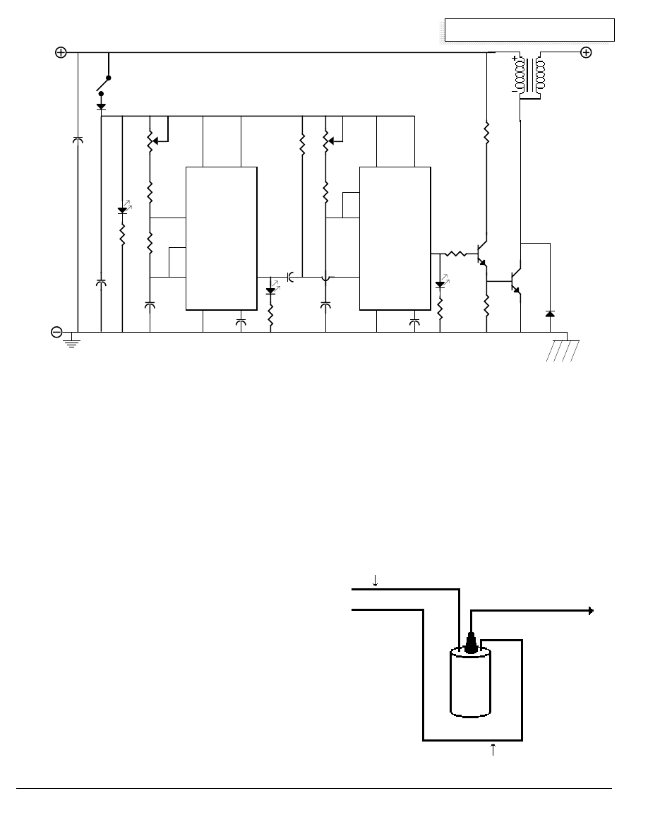
An Electric Fence is Born!
Nine years ago, we faced a serious equine problem. Karen's
horse, an intelligent and sometimes foolhardy Arabian mare named
Oozie, kept escaping. She had no respect for barbed wire.
Oozie's two pervious encounters with barbed wire resulted in
serious cuts, on-site visits by the Vet, and much of Karen' gray hair.
We really needed to keep the horse in her 35 acre pasture without
allowing her to injure herself on barbed wire.
Karen installed over one mile of electric fence to corral her horsie
friend. We went to town and bought a commercial electric fence
charger powered by a car battery. This did the job. High voltage
electricity made a believer of Oozie where the barbed wire failed.
And best of all- no more barbed wire cuts. Everyone was happy
until the fence charger broke.
The first fence charger lasted about two months and died. We
bought another and it lasted about three months. With both
chargers, I was far from pleased with their high power
consumption. The car battery would last only about three weeks
before being totally discharged. These electric fencers were not
built to last and they were power pigs. There had to be a better
way.
I remembered my Time Machine. I considered that an automotive
ignition system used switched pulses into the ignition coil to
produce high voltage. I set about adapting the Time Machine as an
electric fence charger. Since I didn't want to wind my own coil, I
just used an old automotive coil I had on hand. The circuit is a
specific adaptation of the Time Machine and its schematic follows
below.
The only major difference between the Electric Fence and the Time
Machine is the output amplifier. The Electric Fence uses a two
PULSE
C1 or C2
PULSE
FREQUENCY
in µF.
DURATION
10 kHz. to 100 kHz.
0.001 µF.
10 µs. to 100 µs.
1 kHz. to 10 kHz.
0.01 µF.
100 µs. to 1 ms.
100 Hz. to 1kHz.
0.1 µF.
1 ms. to 10 ms.
10 Hz. to 100 Hz.
1.0 µF.
10 ms. to 100 ms.
1 Hz. to 10 Hz.
10 µF.
100 ms. to 1 s.
0.1 Hz. to 1 Hz.
100 µF.
1 s. to 10 s.
TIMING CHART
values of C1 and C2 for the Time Machine
81
Home Power #21 • February / March 1991
Homebrew
stage silicon power amplifier using a 2N2222A and a 2N3055
bipolar transistors. I used this design because it is very rugged
and will survive the incredible high voltage transients that
accompany electric fences. This design has been running here at
Agate Flat since 1982, and for many of my neighbors since 1985.
It works efficiently (average current drain is about 3 Amp-hours per
day) and has survived all variety of lightning storms. The exact
automotive ignition coil you use is not important. I have used
everything from a six volt VW coil to a high energy 12 Volt coil from
a late 1970s Ford. They all work well enough, producing over
20,000 volts on the fence.
In order to function properly every electric fence needs a good
ground. Consider several grounding rods if your soil is dry. Drive
the rods as far as you can into the ground and use at least 8
gauge wire between the charger and the ground rod.
Using the Electric Fence
U1 controls how often the pulses of electricity occur on the fence.
Using the resistors on the schematic the pulses can occur as often
as about 50 pulses per second and as infrequently as one pulse
every two seconds. If you are training livestock to an electric
fence, then keep the frequency high. After the livestock is wary of
the fence, turn the frequency down and save power. U2 controls
the amount of power contained within the pulse. You can adjust
the amount of power to suit your ground conditions (dry ground
has higher resistance and requires more power). I turn our fence
up during the Summer and down during the Winter. You can
adjust the power to suit the length of your fence. We've charged
up over five miles of fence in dry conditions. If you adjust the
amount of power, then you will consume no more power than you
need. BE CAREFUL HERE! Karen once disconnected the
majority of our electric fence and I forgot to reduce the Electric
Fence's power output to compensate. Oozie got across the
super-hot fence and the shock knocked this 1,000 pound horse off
of her feet. She spent the next few hours not feeling at all well.
So, listen up, here comes the caution notice!
CAUTION:
THIS ELECTRIC FENCE MAKES
HIGH VOLTAGE!!!
The basics of safety apply here. Don't let your body get between
the high voltage output of the coil and ground. I did this once and it
0.1 µF.
6
7
2
1
8
4
3
U1
NE555
astable
6
7
1K
Ω
10 K
Ω
330
Ω
0.01µF.
5
POS.
11
to
16
VDC
INPUT
NEG.
1K
Ω
1N4004
0.01µF.
1
5
3
2
0.001 µF.
50
K
Ω
4.7 K
Ω
4.7 K
Ω
50
K
Ω
2.2
K
Ω
0.1
µF.
1000
µF.
4.7 µF.
8
4
U2
NE555
monostable
+
2N222A
2N3055
1 K
Ω
20
Ω
5 W.
180
Ω
1N4004
AUTO
IGNITION
COIL
HIGH
VOLTAGE
TO
ELECTRIC
FENCE
GOOD EARTH GROUND
ELECTRIC FENCE
©1991 Richard Perez
Designed by Richard Perez
CAUTION: THIS DEVICE MAKES HIGH VOLTAGE
Battery terminal on the Ignition Coil is
connected directly to 12 VDC
Auto
Ignition
Coil
HIGH VOLTAGE
to electric fence
Distributor terminal on the Ignition Coil
is switched by the Electric Fence
82
Home Power #21 • February / March 1991
Homebrew
knocked me across the room. Turn the fence OFF if you are doing
repairs. Don't grab ahold of the fence if you are wearing wet boots,
no shoes, or are otherwise grounded. It will shock you. The pulse
emitted by the Electric Fence is high in voltage, but limited in power
because the pulses duration is very short (a few milliseconds).
While many critters and a few foolish humans have tangled with the
fence and gotten shocked plenty, no lifeform has been really
injured. We have noticed that this Electric Fence will kill weeds
that touch it. This is great because vegetation across the fence will
short it out and render it inoperative for shocking livestock. Since
the amount of power is controlled and low, the Electric Fence will
not burn these weeds, hence no fire danger.
ACCESS
Author: Richard Perez, C/O Home Power, POB 130, Hornbrook,
CA 96044 • 916-475-3179.
Time Machine parts: Those interested in mil-spec glass-epoxy,
pre-drilled printed circuit boards for the Time Machine should
contact Bob-O Schultze at Electron Connection, POB 203,
Hornbrook, CA 96044 or call 916-475-3401. Bob-O also has
completely assembled and tested models of the Electric Fence and
Time Machine. Contact him for specifics.
Above: Karen and her friend, Oozie, discuss electric fences. While Oozie is a
notorious escape artist, the electric fence keeps her where she should be.
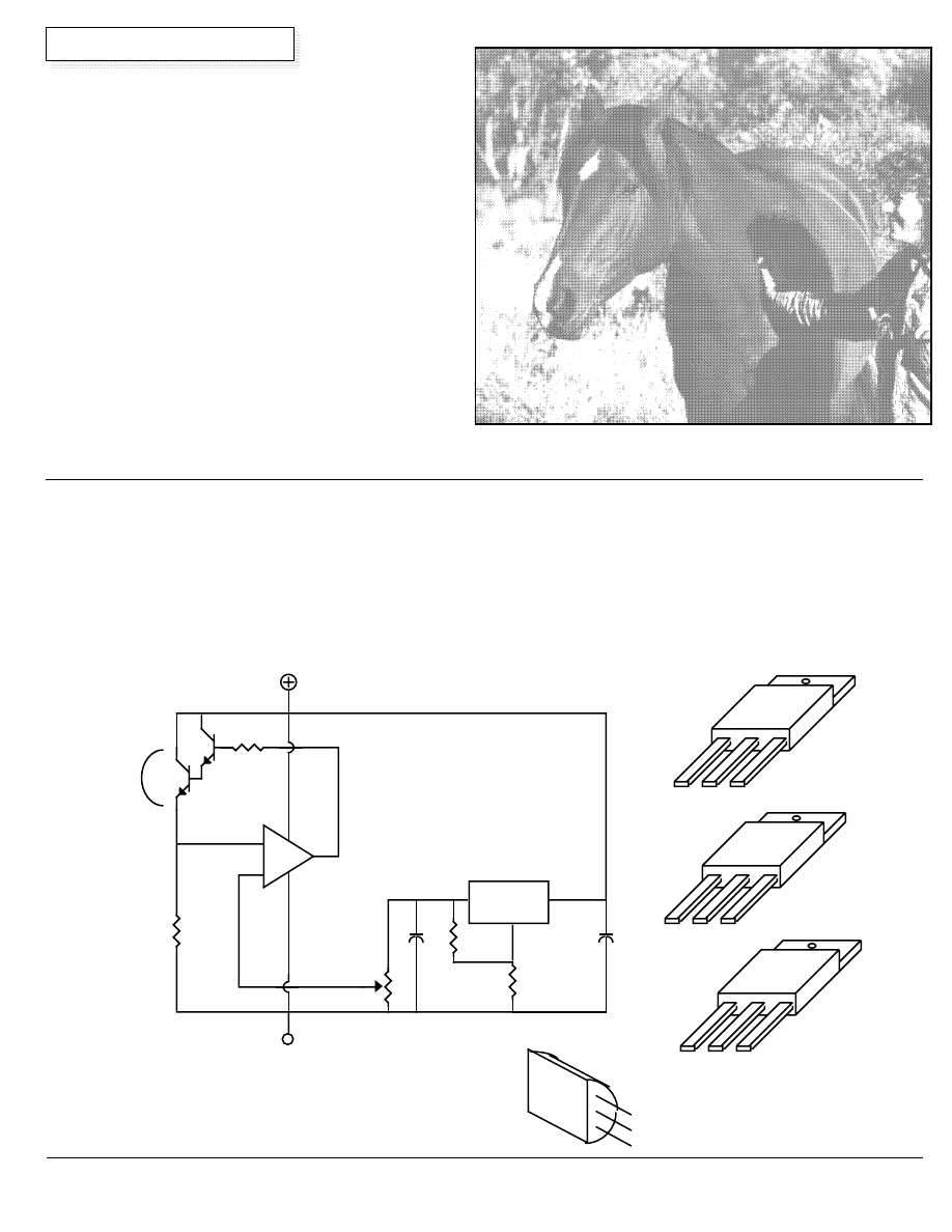
Build a Constant Current Source
Jeff Damm
The best way to recharge Nickel-Cadmium batteries is with a
constant current source. My motivation for designing the circuit in
this article was that I wanted a variable current source which had
the flexibility to charge a variety of different size "NiCads". I also
wanted it to be reproduced easily and relatively inexpensive. Many
hours of tinkering finally produced the circuit shown in figure 1.
Figure 1 is a schematic of the components required to make an
adjustable constant current source from readily available
components. Charging a battery with this circuit is accomplished
by placing the circuit between a positive voltage source ( or current
source, i.e. a PV panel) and the positive terminal of the battery to
be charged. The amount of charging current is set with R2, the 10k
potentiometer. The current is linearly variable between essentially
zero amps and up to 1 amp. More current can be obtained by
lowering the value of the 1 ohm sense resistor.
IN
ADJ
OUT
LM317
G
D
S
IRF511
D
C
B
E
TIP31
C
E
C
B
2N
3904
100
Ω
220
Ω
1k
Ω
LM317
LM358
IN
ADJ
OUT
1
Ω
-
+
HEAT
SINK
Q1
Q2
U1
U2
8
1
4
3
2
R1
10k
Ω
CURRENT
SET
+Vin
Vout
.1µF
.1
µF
R2
Figure1
Wyszukiwarka
Podobne podstrony:
Home Power Magazine Issue 032 Extract p78 Me And My Panel
Home Power Magazine Issue 109 Extract pg22 Making Sense of Solar Electricity Costs
Home Power Magazine Issue 095 Extract p22 Solar Electric Grid Tie
Home Power Magazine Issue 057 Extract p62 Food Dehydrator
Home Power Magazine Issue 072 Extract p34 Solar Hot Air Collectors
Home Power Magazine Issue 032 Extract p22 Whats An Inverter
Home Power Magazine Issue 063 Extract p42 Solar charge controller for Medium Power Applications
Home Power Magazine Issue 109 Extract p12 Off Grid Living In The City
Home Power Magazine Issue 055 Extract p72 Surge Arresters For Lightning And EMP Protection
Home Power Magazine Issue 039 Extract p74 Exceltechs 1000 Watt Sine Wave Inverter
Home Power Magazine Issue 037 Extract p22 Solar Cooker Contest
Home Power Magazine Betting the Farm Wind Electricity Pays Off
Home Power Magazine Before Generating Electricity, Calculate The Load You Will Need (Analysi
Home Power Magazine 024 Extract p26 p30 All Solar Panels Ever Tested
Home Power Magazine Extract Low Voltage Battery Disconnect
Home Power Magazine Extract Installation Basics For Solar Domestic Water Heating Systems Part 2
Home Power Magazine Extract ThermoElectric Generators
Home Power Magazine Extract Installation Basics For Solar Domestic Water Heating Systems Part 1
więcej podobnych podstron