EPSON Stylus Color 440/640/740
Color ink jet printer
4009667
®

Notice:
All rights reserved. No part of this manual may be reproduced, stored in a retrieval system, or transmitted in any form or by any means,
electronic, mechanical, photocopying, recording, or otherwise, without the prior written permission of SEIKO EPSON CORPORATION.
The contents of this manual are subject to change without notice.
All effort have been made to ensure the accuracy of the contents of this manual. However, should any errors be deteced, SEIKO
EPSON would greatly appreciate being informed of them.
The above not withstanding SEIKO EPSON CORPORATION can assume no responsibility for any errors in this manual or the
consequences thereof.
EPSON is a registered trademark of SEIKO EPSON CORPORATION.
General Notice:
Other product names used herein are for identification purpose only and may be trademarks or registered trademarks
of their respective owners. EPSON disclaims any and all rights in those marks.
Copyright © 1996 SEIKO EPSON CORPORATION. Printed in Japan.

PRECAUTIONS
Precautionary notations throughout the text are categorized relative to 1)Personal injury and 2) damage to equipment.
DANGER
Signals a precaution which, if ignored, could result in serious or fatal personal injury. Great caution should be exercised in
performing procedures preceded by DANGER Headings.
WARNING
Signals a precaution which, if ignored, could result in damage to equipment.
The precautionary measures itemized below should always be observed when performing repair/maintenance procedures.
DANGER
1. ALWAYS DISCONNECT THE PRODUCT FROM THE POWER SOURCE AND PERIPHERAL DEVICES PERFORMING ANY
MAINTENANCE OR REPAIR PROCEDURES.
2. NOWORK SHOULD BE PERFORMED ON THE UNIT BY PERSONS UNFAMILIER WITH BASIC SAFETY MEASURES AS DICTATED FOR
ALL ELECTRONICS TECHNICIANS IN THEIR LINE OF WORK.
3. WHEN PERFORMING TESTING AS DICTATED WITHIN THIS MANUAL, DO NOT CONNECT THE UNIT TO A POWER SOURCE UNTIL
INSTRUCTED TO DO SO. WHEN THE POWER SUPPLY CABLE MUST BE CONNECTED, USE EXTREME CAUTION IN WORKING ON
POWER SUPPLY AND OTHER ELECTRONIC COMPONENTS.
WARNING
1. REPAIRS ON EPSON PRODUCT SHOULD BE PERFORMED ONLY BY AN EPSON CERTIFIED REPAIR TECHNICIAN.
2. MAKE CERTAIN THAT THE SOURCE VOLTAGES IS THE SAME AS THE RATED VOLTAGE, LISTED ON THE SERIAL NUMBER/
RATING PLATE. IF THE EPSON PRODUCT HAS A PRIMARY AC RATING DIFFERENT FROM AVAILABLE POWER SOURCE, DO NOT
CONNECT IT TO THE POWER SOURCE.
3. ALWAYS VERIFY THAT THE EPSON PRODUCT HAS BEEN DISCONNECTED FROM THE POWER SOURCE BEFORE REMOVING OR
REPLACING PRINTED CIRCUIT BOARDS AND/OR INDIVIDUAL CHIPS.
4. IN ORDER TO PROTECT SENSITIVE MICROPROCESSORS AND CIRCUITRY, USE STATIC DISCHARGE EQUIPMENT, SUCH AS
ANTI-STATIC WRIST STRAPS, WHEN ACCESSING INTERNAL COMPONENTS.
5. REPLACE MALFUNCTIONING COMPONENTS ONLY WITH THOSE COMPONENTS BY THE MANUFACTURE; INTRODUCTION OF
SECOND-SOURCE ICs OR OTHER NONAPPROVED COMPONENTS MAY DAMAGE THE PRODUCT AND VOID ANY APPLICABLE

PREFACE
This manual describes basic functions, theory of electrical and mechanical operations, maintenance and repair procedures of Stylus Color 440/640/
740. The instructions and procedures included herein are intended for the experienced repair technicians, and attention should be given to the
precautions on the preceding page. The chapters are organized as follows:
CHAPTER 1.
PRODUCT DESCRIPTIONS
Provides a general overview and specifications of the product.
CHAPTER 2.
OPERATING PRINCIPLES
Describes the theory of electrical and mechanical operations of the product.
CHAPTER 3.
TROUBLESHOOTING
Provides the step-by-step procedures for troubleshooting.
CHAPTER 4.
DISASSEMBLY AND ASSEMBLY
Describes the step-by-step procedures for disassembling and assembling the product.
CHAPTER 5.
ADJUSTMENTS
Provides Epson-approved methods for adjustment.
CHAPTER 6.
MAINTENANCE
Provides preventive maintenance procedures and the lists of Epson-approved lubricants and
adhesives required for servicing the product.
APPENDIX
Provides the following additional information for reference:
• Connector pin assignments
• Electric circuit boards components layout
• Exploded diagram
• Electrical circuit boards schematics
REVISION STATUS
Rev.
Date
Page(s)
Contents
A
1998/07/15
All
First Release
B
1998/09/30
Page 188
Pages 195 to 212
The exploded diagrams and part list for the Stylus Color 740 has been added.

Product Description
Features .................................................................................................. 9
Specifications ........................................................................................ 11
Printing Specification........................................................................ 11
Paper Specification .......................................................................... 15
Printing Area..................................................................................... 17
Ink Cartridge Specifications.............................................................. 20
Environmental Condition .................................................................. 22
Electric Specification ........................................................................ 23
Reliability .......................................................................................... 23
Safety Approvals .............................................................................. 23
Acoustic Noise.................................................................................. 24
CE Marking....................................................................................... 24
Input Data Buffer .............................................................................. 24
Interface................................................................................................. 25
Parallel Interface (Forward Channel) ............................................... 25
Parallel Interface (Reverse Channel) ............................................... 27
Serial Interface (for Stylus Color 640, 740) ...................................... 31
Control Panel......................................................................................... 32
Indicators (LEDs).............................................................................. 32
Panel Functions................................................................................ 33
Printer Condition and Panel Status .................................................. 34
Error Status ........................................................................................... 35
Ink Out.............................................................................................. 35
Paper Out ......................................................................................... 35
Paper Jam ........................................................................................ 35
No Ink-Cartridge ............................................................................... 36
Maintenance Request ...................................................................... 36
Fatal Errors....................................................................................... 36
Printer Initialization ................................................................................ 37
Initialization Settings.............................................................................. 37
Main Components ................................................................................. 38
Printer Mechanism ........................................................................... 38
C206 Main-B Board (Stylus Color 440) ............................................ 39
C256 Main Board (Stylus Color 640)................................................ 39
C257 Main Board (Stylus Color 740)................................................ 40
Power Supply Board
C206 PSB/PSE (Stylus Color 440, 640)
C257 PSB/PSE (Stylus Color 740)................................................... 40
C206 PNL Board (Stylus Color 440, 640)......................................... 41
C209 PNL Board (Stylus Color 740)................................................. 41
Operating Principles
Overview................................................................................................ 43
Printer Mechanism............................................................................ 44
Electrical Circuit Operating Principles.................................................... 56
C206 PSB/PSE and C257 PSB/PSE Power Supply Board (for Stylus Color
440, 640, 740) .................................................................................. 57
C206 Main-B, C255 Main (for Stylus Color 440) .............................. 60
C256 Main (for Stylus Color 640) ..................................................... 62
C257 Main, (for Stylus Color 740) .................................................... 64
Troubleshooting
Troubleshooting ..................................................................................... 82
Unit Level Troubleshooting .................................................................... 85
Printer does not operate at power on. .............................................. 85
Error is detected ............................................................................... 86
Failure occurs during printing ........................................................... 86
Printer does not feed paper correctly. .............................................. 87
Control panel operation is abnormal................................................. 87
Unit Repair of Power Supply Board ....................................................... 88
Unit Repair of the Main Board ............................................................... 91
Repair of the Printer Mechanism ........................................................... 96
Disassembly and Assembly
Overview.............................................................................................. 100
Precautions for Disassembling the Printer ..................................... 100
Tools............................................................................................... 101
Specification for Screws ................................................................. 102
Service Checks After Repair .......................................................... 103

Disassembly Procedures..................................................................... 104
Removing the Housing ................................................................... 105
Removing the Board Assembly ...................................................... 106
Removing the Operation Panel ...................................................... 108
Disassembling the Printer Mechanism ........................................... 109
Adjustment
Overview.............................................................................................. 130
Required Adjustments .................................................................... 130
Adjustment Tools Required ............................................................ 131
Adjustment........................................................................................... 132
Parallelism Adjustment................................................................... 132
Adjustment by Adjustment Program............................................... 134
Maintenance
Overview.............................................................................................. 154
Cleaning ......................................................................................... 154
Service Maintenance...................................................................... 154
Lubrication...................................................................................... 155
Appendix
Connector Summary............................................................................ 161
Connector Summary (Stylus Color 440/640).................................. 162
Connector Summary for Stylus Color 740...................................... 166
EEPROM Address Map....................................................................... 169
EEPROM ADDRESS Map (Stylus Color 440/640)......................... 169
EEPROM Address Map (Stylus Color 740).................................... 174
Circuit Board Component Layouts....................................................... 178
Exploded Diagrams ............................................................................. 188
Part List ............................................................................................... 198
Part List for Stylus Color 440/640.................................................. 198
Part List for Stylus Color 740......................................................... 200
Circuit Diagrams .................................................................................. 202

PRODUCT DESCRIPTION

EPSON Stylus Color 440/640/740
Revision A
Chapter 1
Product Description
9
1.1 FEATURES
EPSON Stylus Color 440/640/740 are designed for PC users at home
and low price for hat high performance. Also, Stylus Color 440 printer
has the same high color print quality (720 X 720dpi) as Stylus ProXL,
and Stylus Color 640,740 have the same high color print quality (1440 X
720) as Stylus Color 600 and Stylus Pro 5000. The major printer
features are;
High color print quality
720 (H) x 720 (V) dpi printing (for Stylus Color 440)
1440 (H) X 720 (V) dpi printing (for Stylus Color 640,740)
4 color printing (YMCBk)
Traditional and New Microwave
Black 64 nozzles, CMY 21 nozzles (for Stylus Color 440)
Black 64 nozzles, CMY 32/color nozzles (for Stylus Color 640)
Black 144 nozzles, CMY 48/color nozzles (for Stylus Color 740)
Built-in auto sheet feeder
Holds 100 cut-sheets (55g/m
2
)
Holds 10 envelopes
Holds 10 transparency films
Holds 65 special papers
High-speed print
200 cps (for Stylus Color 440, 740)
Normal 200 cps, Draft 400 cps (only for Stylus Color 640)
By using head drive frequency 14.4KHz, printing speed is twice
faster
than Stylus Color.
Compact size
429mm (W) x 231mm (D) x 155mm (H) (for Stylus Color 440)
429mm (W) x 231mm (D) x 157mm (H) (for Stylus Color 640)
429mm (W) x 261mm (D) x 157mm (H) (for Stylus Color 740)
Weight : 5.2Kg (for 3 models)
Acoustic noise
Approximately 45 dB (for Stylus Color 440)
Approximately 47 dB (for Stylus Color 640, 740)
Interface
Bi-directional parallel I/F IEEE-1284 level 1 device (for 3
models)
Serial I/F up to 1800 bps (only for Stylus Color 640)
USB
One unit combined black and CMY head
Windows exclusive (for Stylus Color 440, 640)
Standard, NLSP, 5 Scaleable fonts (only for Stylus Color 740)
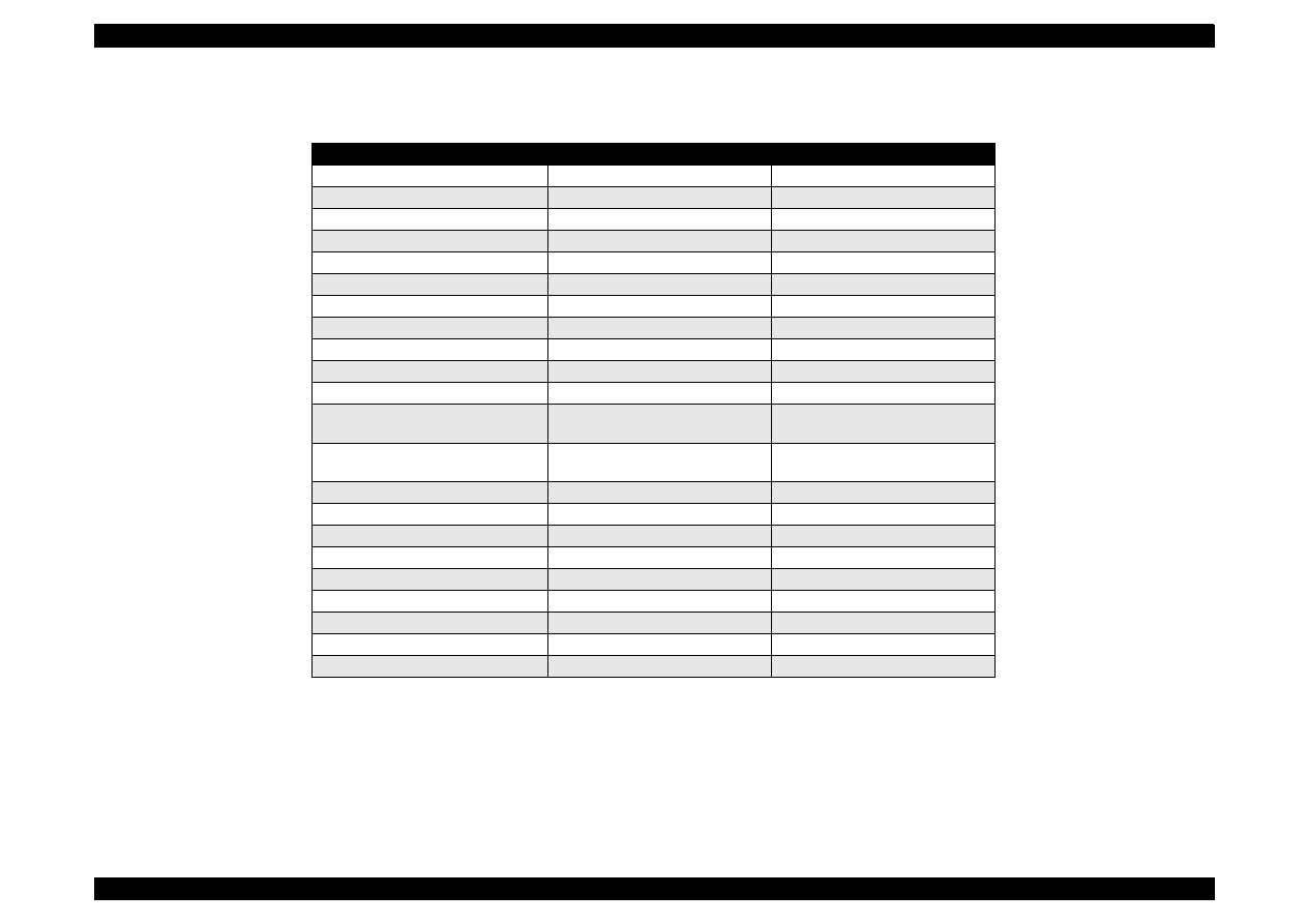
See Table 1-1 in the following page for the consumable list.
EPSON Stylus Color 440/640/740
Revision A
Chapter 1
Product Description
10
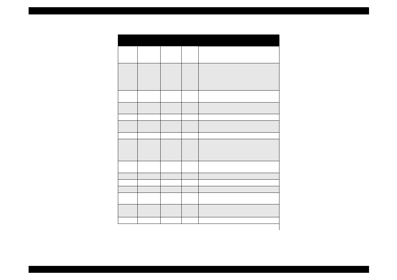
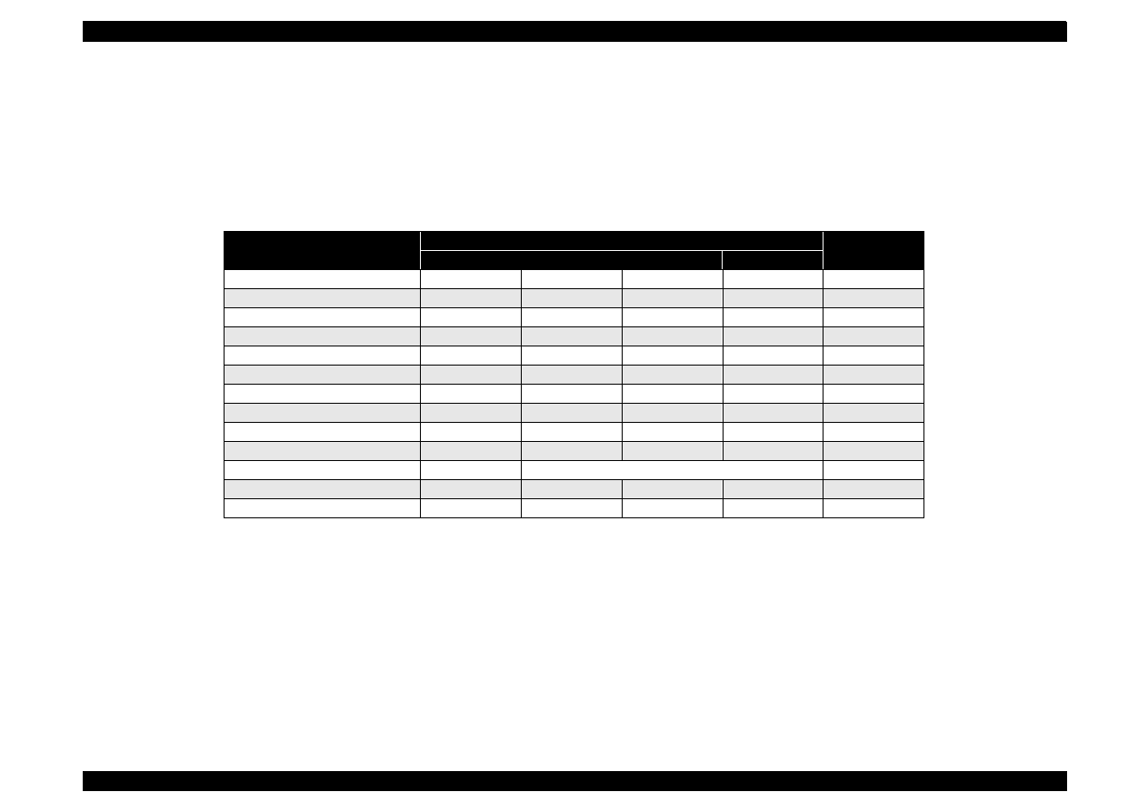
Table 1-1. Consumables Available for Stylus Color 440/640/740
Items
Codes
Remarks
Black Ink Cartridge
S020189
Stylus Color 740
Black Ink Cartridge
S020187
Stylus Color 440,640
CMY Ink Cartridge
S020191
Stylus Color 440,640,740
CMY Ink Cartridge
EPSON 360 dpi Ink Jet Paper
S041025
Size: A4 (200 sheets)
EPSON 360 dpi Ink Jet Paper
S041059
Size: A4 (100 sheets)
EPSON 360 dpi Ink Jet Paper
S041060
Size: Letter (100 sheets)
Photo Quality Ink Jet Paper
S041026
Size: A4 (200 sheets)
Photo Quality Ink Jet Paper
S041061
Size: A4 (100 sheets)
Photo Quality Ink Jet Paper
S041062
Size: Letter
Photo Quality Ink Jet Paper
S041067
Size: Legal
Photo Quality Glossy Paper (New
Release)
S041126
Size: A4
Photo Quality Glossy Paper (New
Release)
S041124
Size: Letter
Photo Quality Glossy Film
S041071
Size: A4
Photo Quality Glossy Film
S041124
Size: Letter
Photo Quality Glossy Film
S041107
Size: A6
Ink Jet Transparencies
S041063
Size: A4
Ink Jet Transparencies
S041064
Size: Letter
Photo Quality Ink Jet Card
S041054
Size: A6
Photo Quality Ink Jet Card
S041121
Size: 5 x 8 inches
Photo Quality Ink Jet Card
S041122
Size: 10 x 8 inches
Photo Quality Self Adhesive Sheet
S041106
Size: A4
EPSON Stylus Color 440/640/740
Revision A
Chapter 1
Product Description
11
1.2 Specifications
This section describes each specification for Stylus Color 440, 640, and
740.
1.2.1 Printing Specification
Print method
On demand ink jet (MACH type. One unit combined with black
and CMY head)
Nozzle configuration
Black 64 nozzles, CMY 21 nozzles (for Stylus Color 440)
Black 64 nozzles, CMY 32/color nozzles (for Stylus Color 640)
Black 144 nozzles, CMY 48/color nozzles (for Stylus Color 740)
Print direction
Bi-direction with logic seeking
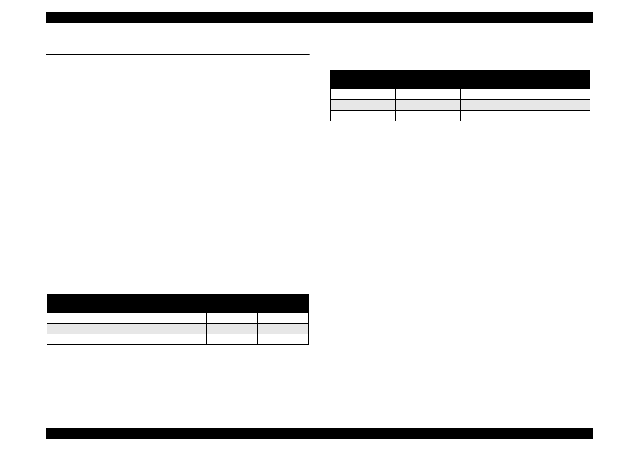
Print speed and Printable columns, character pitch and print quality
Refer to Table 1-2 and Table 1-3.
Table 1-2. Character Mode Speed
Table 1-3. Graphic Mode Speed
Nozzle Configuration:
Refer to Figure 1-1 for Stylus Color 440.
Refer to Figure 1-2 for Stylus Color 640.
Refer to Figure 1-3 for Stylus Color 740.
Model Name
Character
Pitch
Printable
Column
LQ Speed
Draft Speed
Stylus Color 440
10
80
200 CPS
---
Stylus Color 640
10
80
200 CPS
400 CPS
Stylus Color 740
10
80
200 CPS
---
Horizontal
Resolution
Printable Area
Available dot
CR Speed
180 dpi
8.26
1488
20 IPS
360 dpi
8.26
2976
20 IPS
720 dpi
8.26
5952
20 IPS
EPSON Stylus Color 440/640/740
Revision A
Chapter 1
Product Description
12
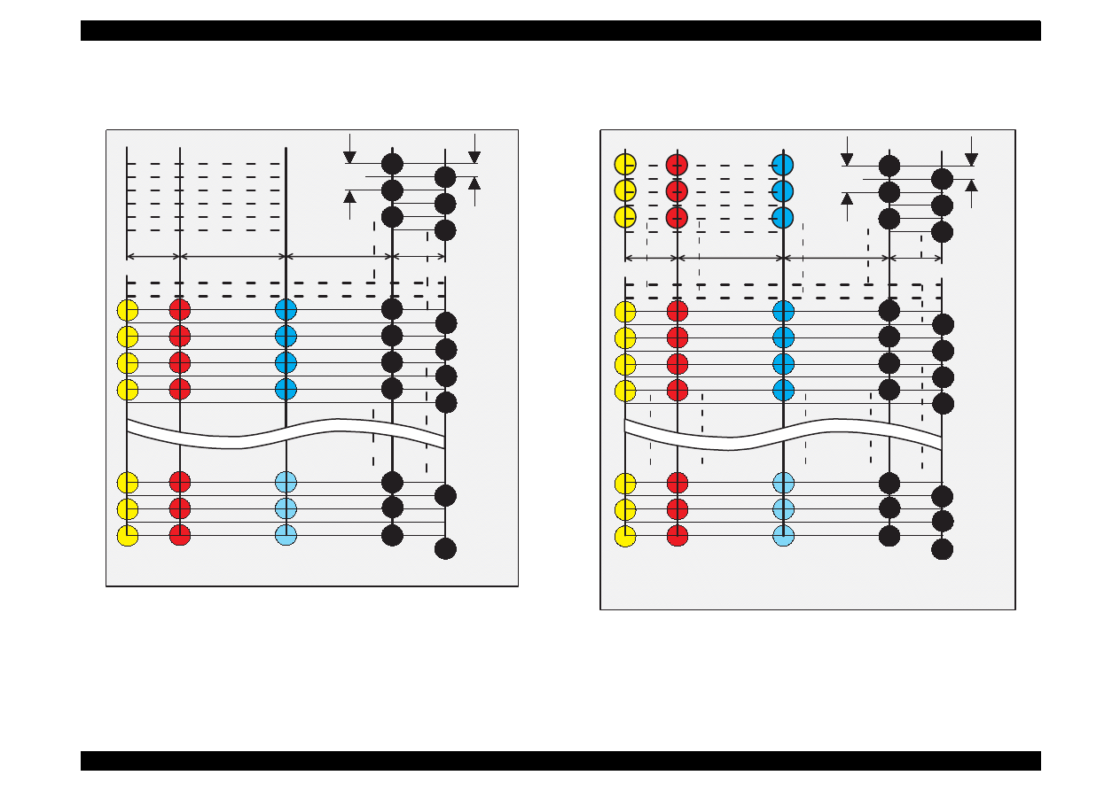
Figure 1-1. Nozzle Configuration for Stylus Color 440
Figure 1-2. Nozzle Configuration for Stylus Color 640
(B2)
#27
#1
#2
#3
#5
C2
C3
C4
Y2
Y3
Y4
(C)
(M)
(Y)
90DPI
180DPI
#23
#24
Y20
Y21
#60
#62
#64
#59
#61
#25
#26
2.2578 mm
7.9022 mm
10.16 mm
2.2578 mm
(B1)
#63
C1
C19
C20
C21
M 1
M 2
M 19
M 20
M 21
M 3
M 4
Y1
Y19
#4
#6
#29
(B2)
#27
#1
#2
#3
#5
C13
C14
C15
(C)
(M)
(Y)
90DPI
180DPI
#23
#24
#60
#62
#64
#59
#61
#25
#26
2.2578 mm
7.9022 mm
10.16 mm
2.2578 mm
(B1)
#63
C12
C30
C31
C32
#4
#6
#29
C1
C2
C3
M13
M14
M15
M12
M30
M31
M32
M1
M2
M3
Y13
Y14
Y15
Y12
Y30
Y31
Y32
Y1
Y2
Y3
EPSON Stylus Color 440/640/740
Revision A
Chapter 1
Product Description
13
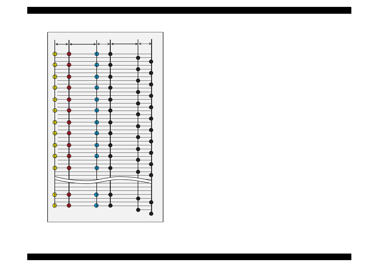
Figure 1-3. Nozzle Configuration for Stylus Color 740
Feeding method
Friction feed with ASF
Line spacing
1/6 inches or programmable at 1/360 inches (only for Stylus
Color 440)
1/6, 1/8 inches or programmable at 1/360 inches (for Stylus
Color 640,740)
Paper path
Cut-sheet ASF (Top entry)
Feeding speed
<Stylus Color 440, 640>
190 ms (1/3 inch)
2.0 inches/seconds (continuous)
<Stylus Color 740>
110 ms (10.16 mm)
114.3 mm/second (Continuous)
Ink supply
Exclusive ink cartridge (Black and CMY)
(B2)
#1
(C)
(M)
(Y)
(B1)
#2
#3
#4
#7
#10
#13
#16
#19
#22
#25
#28
#31
#5
#8
#11
#14
#17
#20
#23
#26
#29
#32
#6
#9
#12
#15
#18
#21
#23
#26
#29
#32
#139
#140
#141
#142
#143
#144
#1
#2
#3
#4
#5
#6
#7
#8
#9
#10
#11
#1
#2
#3
#4
#5
#6
#7
#8
#9
#10
#11
#47
#48
#2
#3
#4
#5
#6
#7
#8
#9
#10
#11
#1
#47
#48
#47
#48
(B3)
32/360"
112/360"
32/360"
112/360"
32/360"

EPSON Stylus Color 440/640/740
Revision A
Chapter 1
Product Description
14
Paper holding capacity of Hopper
Size:
Index card
∼
Legal
Thickness:
Less than 8mm
Paper capacity:
100 Cut sheets
10 Envelopes
65 Coated papers (360 dpi)
65 Coated papers (720 dpi)
20 Glossy papers, Photo Paper
10 Transparent sheets
30 Index cards
1 Panoramic Photo Paper, Iron-On Cool Peel
Transfer Paper, and Photo Sticks,
Glossy Film, Self Adhesive
Character tables:
2 international character sets (Not Opened)
<Stylus Color 440, 640>
PC437 (US, Standard Europe)
PC850 (Multilingual)
Typeface
Bit map LQ font:
EPSON Courier 10CPI
<Stylus Color 740>
Standard version:11 character tables
Italic table, PC437 (US Standard, Europe), PC 850
(Multilingual), PC860 (Portuguese), PC861 (Icelandic), PC863
(Canadian-French), PC865 (Nordic), Abicomp, BRASCII,
Roman 8, ISO Latin 1
NLSP Version:
30 character tables
Italic table, PC437, PC437 Greek, PC 850, PC852, PC853, PC855,
PC857, PC860, PC861, PC865, PC866, ISO8859-7, ISO Latin 1T,
Bulgaria, ic), PC774, Estonia, ISO 8859-2, PC866-LAT, PC866 UKR,
PC AR864, PC APTEC, PC708, PC720, Hebrew7
*1
Hebrew8
*1
,
PC862
*1
NOTE:
*1
is not opened. These character tables can not be selected in
the default setting mode.
Typeface
Bit map LQ font:
EPSON Roman
10 CPI, 12 CPI, 15 CPI, Proportional
EPSON Sans Serif
10 CPI, 12 CPI, 15 CPI, Proportional
EPSON Courier
10 CPI, 12 CPI, 15 CPI
EPSON Prestige
10 CPI, 12 CPI, 15 CPI
EPSON Script
10 CPI, 12 CPI, 15 CPI
Scaleable font:
EPSON Roman
10.5pt., 8pt. to 32 pt. (every 2 pt. unit)
EPSON Sans Serif
10.5pt., 8pt. to 32 pt. (every 2 pt. unit)
EPSON Roman T
10.5pt., 8pt. to 32 pt. (every 2 pt. unit)
EPSON Sans Serif H 10.5pt., 8pt. to 32 pt. (every 2 pt. unit)
NOTE: The above typeface has 4 variations individually as follows;
EPSON Roman, EOSON Roman bold
EPSON Roman Italic, EPSON Roman bold Italic
Control code
<Stylus Color 440, 640>
ESC/P Raster
EPSON Remote command
<Stylus Color 740>
ESC/P2 and ESC/P Raster
EPSON Remote command

EPSON Stylus Color 440/640/740
Revision A
Chapter 1
Product Description
15
1.2.2 Paper Specification
This section describes the printable area and types of paper that can be
used in this printer.
1.2.2.1 Cut Sheet
[Size]
A4:
[Width 210mm (8.3”) x Length 297mm (11.7”)]
Letter:
[Width 216mm (8.5”) x Length 279mm (11.0”)]
B5:
[Width 182mm (7.2”) x Length 257mm (10.1”)]
Legal:
[Width 216mm (8.5”) x Length 356mm (14.0”)]
Statement:[Width]139.7mm (5.5”) x Length 215.9mm (8.5”)]
Exclusive: [Width 190.5mm (7.5”) x Length 254mm (10”)]
[Thickness]
0.08mm (0.003”) - 0.11mm (0.004”)
[Weight]
64g/m
2
(17Ib.) - 90g/m
2
(24Ib.)
[Quality]
Exclusive paper, Bond paper, PPC
1.2.2.2 Transparency, Glossy Paper
[Size]
A4:
[Width 210mm (8.3”) x Length 297mm (11.7”)]
Letter:
[Width 216mm (8.5”) x Length 279mm (11.0”)]
[Thickness]
0.075mm(0.003”) - 0.085mm(0.0033”)
NOTE: Transparency printing is only available at normal temperature.
1.2.2.3 Envelope
[Size]
No.10 Width 241mm (9 1/2”) x Length 104.8mm (4 1/8”)
DL Width 220mm (8.7”) x Length 110mm (4.3”)
C6 Width 162mm (6.4”) x Length 114mm (4.5”)
[Thickness]
0.16mm (0.006”) - 0.52mm (0.02”)
[Weight]
45g/m
2
(12Ib.) - 75g/m
2
(20Ib.)
[Quality]
Bond paper, Plain paper, Air mail
NOTE 1 Envelope printing is only available at normal temperature.
NOTE 2 Keep the longer side of the envelope horizontally at setting.

EPSON Stylus Color 440/640/740
Revision A
Chapter 1
Product Description
16
1.2.2.4 Index Card
[Size]
A6 Index card:
Width 105mm (4.1”) x Length 148mm (5.8”)
A5 Index card:
Width 148mm (5.8”) x Length 210mm (8.3”)
5x8” Index card:
Width 127mm (5.0” x Length 203mm (8.0”)
10x8” Index card:
Width 127mm (5.0”) x Length 203mm (8.0”)
[Thickness]
: Less than 0.23mm (0.0091”)
EPSON Stylus Color 440/640/740
Revision A
Chapter 1
Product Description
17
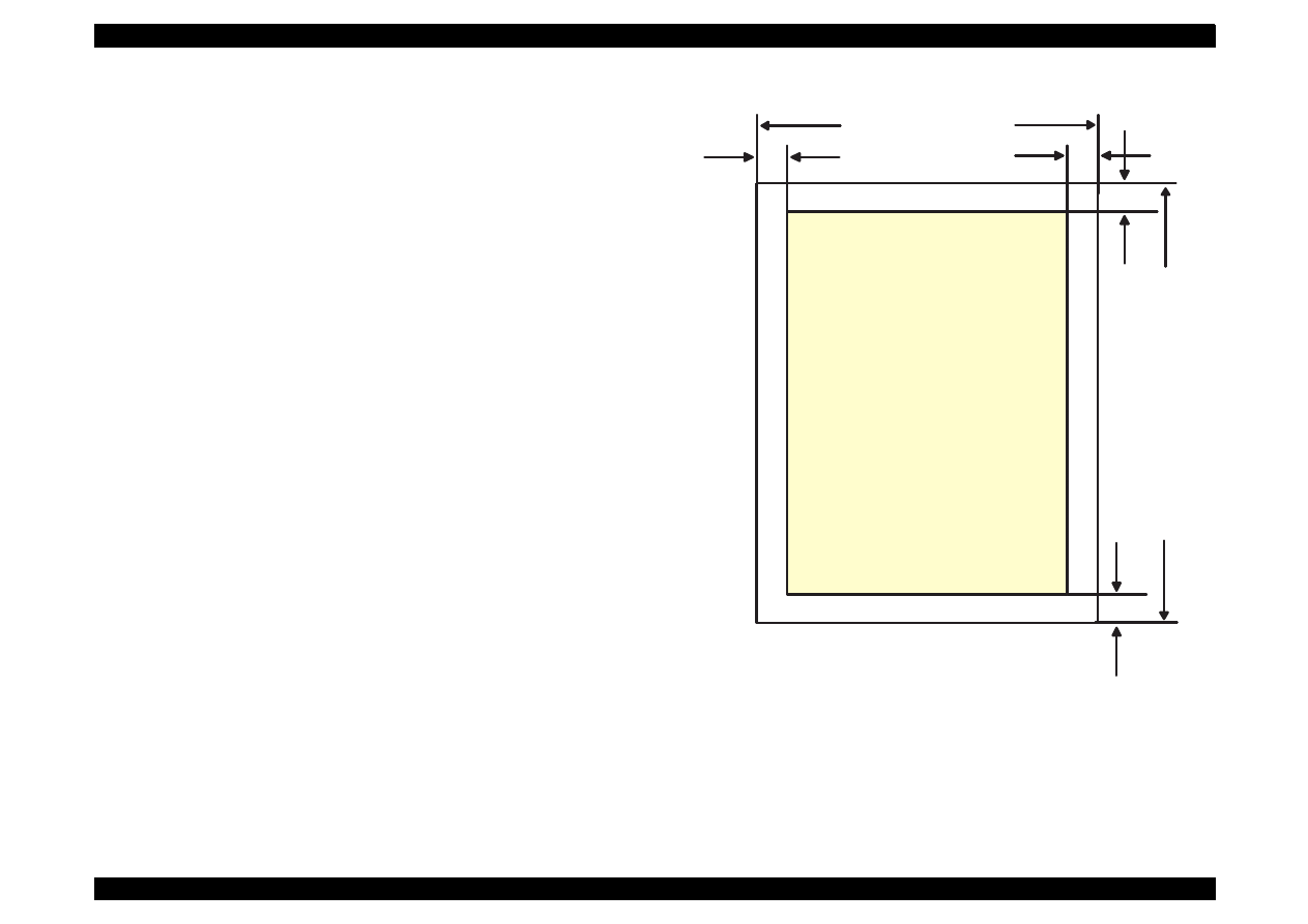
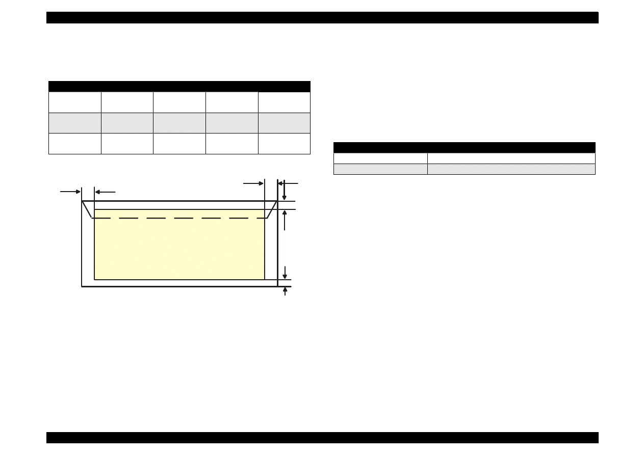
1.2.3 Printing Area
[Cut Sheet]
See Figure 1-4 in the right column and the tables in the following page
for the printable areas for Raster Graphics mode and Character mode.
NOTE: Character mode is only suitable for Stylus Color 740.
Figure 1-4. Printable Area for Cut sheet
PW
RM
LM
BM
TM
PL
Printable
Area
EPSON Stylus Color 440/640/740
Revision A
Chapter 1
Product Description
18
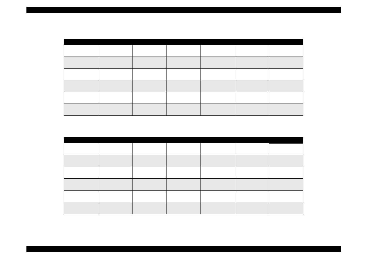
Table 1-4. Raster Graphics Mode (for 3 models)
Paper Size
PW
PL
LM
RM
TM
BM/min.
A4
210 mm (8.3”)
297 mm (11.7”)
3 mm (0.12”)
3 mm (0.12”)
3 mm (0.12”)
14 mm(0.54”)
3 mm (0.12”)
Letter
216 mm (8.5”)
279 mm (11.0”)
3 mm (0.12”)
9 mm (0.35”)
3 mm (0.12”)
14 mm (0.54”)
3 mm (0.12”)
B5
182 mm (7.2”)
257 mm (10.1”)
3 mm (0.12”)
3 mm (0.12”)
3 mm (0.12”)
14 mm (0.54”)
3 mm (0.12”)
Legal
216 mm (8.5”)
356 mm (14.0”)
3 mm (0.12”)
9 mm (0.35”)
3 mm (0.12”)
14 mm (0.54”)
3 mm (0.12”)
Statement
139.7 mm (5.5”)
215.9 mm (8.5”)
3 mm (0.12”)
3 mm (0.12”)
3 mm (0.12”)
14 mm (0.54”)
3 mm (0.12”)
Exclusive
190.5 mm (7.5”)
254 mm (10”)
3 mm (0.12”)
3 mm (0.12”)
3 mm (0.12”)
14 mm (0.54”)
3 mm (0.12”)
Table 1-5. Character Mode (only for Stylus Color 740)
Paper Size
PW
PL
LM
RM
TM
BM/min.
A4
210mm (8.3”)
297mm (11.7”)
3mm (0.12”)
3mm (0.12”)
3mm (0.12”)
14mm (0.54”)
3 mm (0.12”)
Letter
216mm (8.5”)
279mm (11.0”)
3mm (0.12”)
9mm (0.35”)
3mm (0.12”)
14mm (0.54”)
3 mm (0.12”)
B5
182mm (7.2”)
257mm (10.1”)
3mm (0.12”)
3mm (0.12”)
3mm (0.12”)
14mm (0.54”)
3 mm (0.12”)
Legal
216mm (8.5”)
356mm (14.0”)
3mm (0.12”)
9mm (0.35”)
3mm (0.12”)
14mm (0.54”)
3 mm (0.12”)
Statement
139.7mm (5.5”)
215.9mm (8.5”)
3mm (0.12”)
3mm (0.12”)
3mm (0.12”)
14mm (0.54”)
3 mm (0.12”)
Exclusive
190.5mm (7.5”)
254mm (10”)
3mm (0.12”)
3mm (0.12”)
3mm (0.12”)
14mm (0.54”)
3 mm (0.12”)
EPSON Stylus Color 440/640/740
Revision A
Chapter 1
Product Description
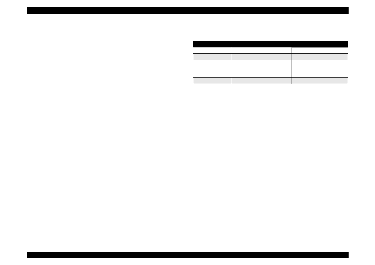
19
[Envelope]
Table 1-6 and Figure 1-5 show the printable area for envelopes.
Table 1-6. Envelopes Margin
Figure 1-5. Printable Area for Envelopes
1.2.3.1 Adjust Lever Setting
The adjustment lever located on the right side (dark blue) under the
printer cover needs to be set to the proper position according to the
paper you print. (Refer to the Table 1-7.) Also, if there is any dirt caused
by friction on the way or wrinkled paper, this can be prevented by
changing the lever position to rear position (marked with “+”) in spite of
paper types.
Table 1-7. Adjust Lever Setting
NOTE: Return the adjust lever to the zero position, which is normal
position, after you finish printing on all media. Leaving the lever
in the plus position may cause the printed image to have gaps
on other media.
Paper Size
LM
RM
TM
BM/min.
#10
28 mm (1.10”)
3 mm (0.12”)
3 mm (0.12”)
14 mm (0.54”)
3 mm (0.12”)
DL
7 mm (0.28”)
3 mm (0.12”)
3 mm (0.12”)
14 mm (0.54”)
3 mm (0.12”)
C6
3 mm (0.12”)
3 mm (0.12”)
3 mm (0.12”)
14 mm (0.54”)
3 mm (0.12”)
RM
TM
LM
Printable
Area
BM
Lever Position
Clearance between head and platen
Plus Position
1.04 mm
Zero Position
1.74 mm (+0.7 mm)
EPSON Stylus Color 440/640/740
Revision A
Chapter 1
Product Description
20
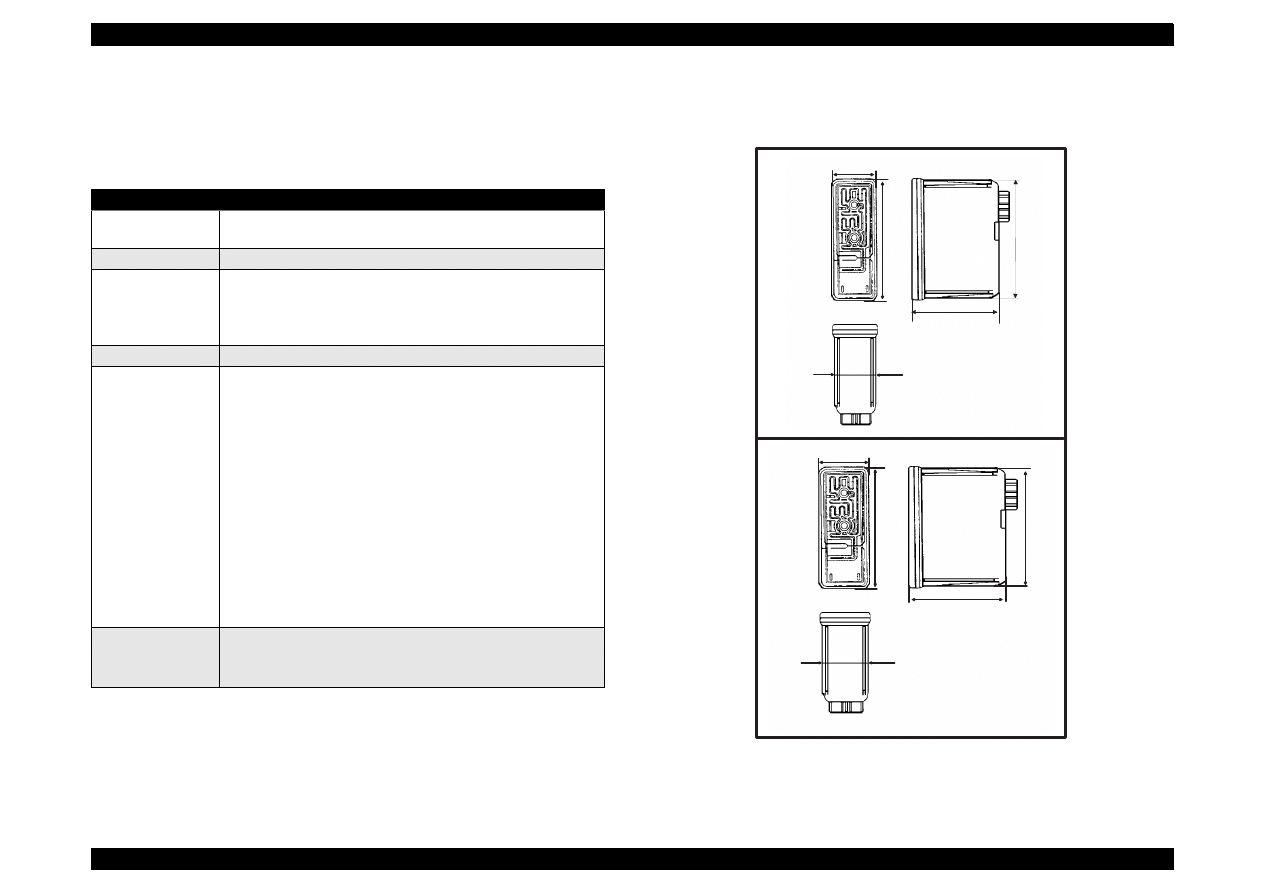
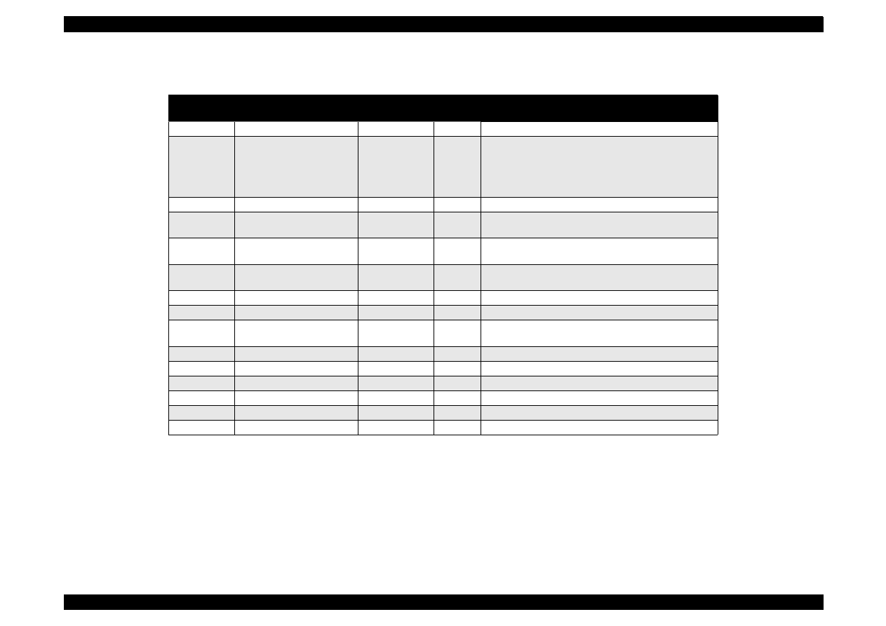
1.2.4 Ink Cartridge Specifications
[Black Ink Cartridge]
Figure 1-6. Black Ink Cartridge Appearance
Table 1-8. Black Cartridge Specifications
Items
Specifications
Type
Exclusive Cartridge for Stylus Color 440, 640
Exclusive Cartridge only for Stylus Color 740
Color
Black
Print Capacity
<Stylus Color 440,640>
540 pages / A4 (ISO/IEC 10561 Letter Pattern at 360 dpi)
<Stylus Color 740>
900 pages / A4 (ISO/IEC 10561 Letter Pattern at 360 dpi)
Validity
2 years (sealed in package) / 6 months (out of package)
Environmental
conditions
• Temperature
- Storage: -20
°
C~40
°
C (within a month at 40
°
C)
- Packing storage: -30
°
C~40
°
C (within a month at 40
°
C)
- Transit: -30
°
C~60
°
C (within 120 hours at 60
°
C and within
a month at 40
°
C)
• Humidity
5% to 85% (without condensation)
Note:
Ink freezes below -3
°
C, but it returns to normal after 3 hours at
room temperature. (25
°
C)
• Dimension
<Stylus Color 440,640>
19.8 mm (W) X 52.7 mm (D) X 38.5 mm (H)
<Stylus Color 740>
27.8 mm (W) X 52.7 mm (D) X 38.5 mm (H)
Weight
Total Ink Cartridge: 30 g
Total Ink: 16.4 +/-0.5 g
Consumable Ink weight: more than 12.1 g
1 8 . 3
3 8 . 5
5 1 . 2
1 9 . 8
5 2 . 7
2 7 . 8
5 2 . 7
3 8 . 5
5 1 . 2
2 6 . 3
1 8 . 3
3 8 . 5
5 1 . 2
1 9 . 8
5 2 . 7
f o r S t y l u s C o l o r 4 4 0 , 6 4 0
f o r S t y l u s C o l o r 7 4 0
EPSON Stylus Color 440/640/740
Revision A
Chapter 1
Product Description
21
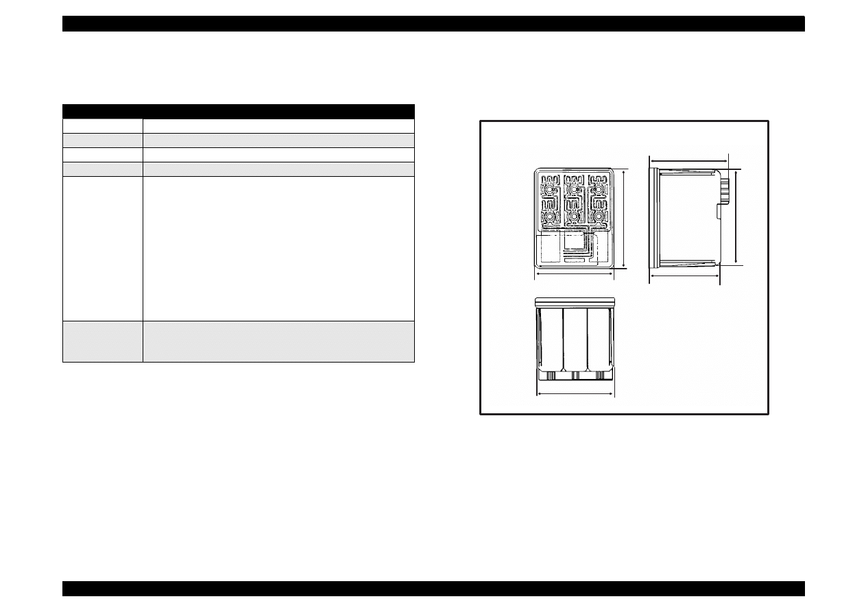
[Color Ink Cartridge]
Figure 1-7. Color Ink Cartridge
Table 1-9. Color I/C Specifications
Items
Specifications
Type
Exclusive Cartridge for Stylus Color 440, 640, 740
Color
CMY
Print Capacity
300 pages / A4 (360 dpi, 5% duty each colors)
Validity
2 years (sealed in package) / 6 months (out of package)
Environmental
conditions
• Temperature
- Storage: -20
°
C~40
°
C (within a month at 40
°
C)
- Packing storage: -30
°
C~40
°
C (within a month at 40
°
C)
- Transit: -30
°
C~60
°
C (within 120 hours at 60
°
C and within a
month at 40
°
C)
• Humidity
5% to 85% (without condensation)
Note:
Ink freezes below -3
°
C, but it returns to normal after 3 hours at
room temperature. (25
°
C)
• Dimension
42.9 mm (W) X 52.7 mm (D) X 38.5 mm (H)
Weight
Total Ink Cartridge: 67 g
Total Ink: 12.8 +/-0.5 g/colors
Consumable Ink weight: more than 9.6 g/colors
4 1 . 4
3 8 . 5
5 1 . 2
4 3 . 2
4 2 . 9
5 2 . 7
EPSON Stylus Color 440/640/740
Revision A
Chapter 1
Product Description
22
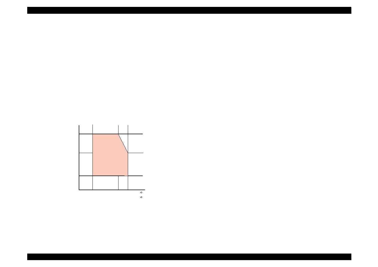
1.2.5 Environmental Condition
Temperature
Operating :10 to 35
°
C (Refer to Figure 1-8 for condition)
Non-operating:-20 to 60
°
C (with shipment container)
NOTE: 1 month at 40
°
C and 120 hours at 60
°
C
Humidity
Operating:
20% ~ 80% RH
(without condensation Refer to Figure 1-8 for condition)
Non-operating:
5% ~ 85% RH
(without condensation and with shipment container)
Figure 1-8. Temperature / Humidity of Range
Resistance to shock
Operating:
1G, within 1 ms
X,Y,Z directions
Non-operating:2G, within 2 ms
X,Y,Z directions (with shipment container)
Resistance to vibration
Operating:
0.15G (Operating)
Non-operating:0.50G (Non-Operating)
NOTE 1:During non-operating, make sure that the head is capped.
NOTE 2:During the transport, make sure that the head is capped and
ink cartridge is installed to the printer.
NOTE 3: If the head is not capped at the power-off state, turn the power
on with installed ink cartridge and turn off the power after
confirming that Power on operation is completed and the head
is capped.
NOTE 4: Ink will be frozen less than -3
°
C environment, however it
will be usable after placing it more than 3 hours at 25
°
C.
Humidity
(% RH)
80%
55%
20%
10
27
35
50
( C )
80
95 ( F )
Guaranteed
Area

EPSON Stylus Color 440/640/740
Revision A
Chapter 1
Product Description
23
1.2.6 Electric Specification
[120V version]
[Rated voltage]
AC120V
[Input voltage range]
AC99
∼
132V
[Rated frequency range] 50
∼
60Hz
[Input frequency range]
49.5
∼
60.5Hz
[Rated current
0.4A (Max. 0.5A)
[Power consumption]
Approx.15W (ISO/IEC 10561 Letter pattern)
Energy Star compliant
[Insulation Resistance]
10M ohms min.
(between AC line and chassis, DC 500 V)
[Dielectric strength]
AC1000 V rms. 1 minute or AC1200 Vrms.
1 second (between AC line and chassis)
[220
∼
240V version]
[Rated voltage]
AC220V
∼
240V
[Input voltage range]
AC198
∼
264V
[Rated frequency range] 50
∼
60Hz
[Input frequency range]
49.5
∼
60.5Hz
[Rated current]
0.2 A (Max. 0.3A)
[Power consumption]
Approx.15W (ISO/IEC 10561 Letter pattern)
Energy Star compliant
[Insulation Resistance]
10M ohms min.
(between AC line and chassis, DC500V)
[Dielectric strength]
AC1500 V rms.
1 minute (between AC line and chassis)
1.2.7 Reliability
[Total print volume]
Stylus Color 440:
10,000 pages (A4, Letter)
Stylus Color 640:
25,000 pages (A4, Letter)
Stylus Color 740:
75,000 pages (A4, Letter)
[Print head life]
Stylus Color 440:
2000 million dots/nozzle
Stylus Color 640:
2000 million dots/nozzle
Stylus Color 740:
4000 million dots/nozzle
1.2.8 Safety Approvals
[120V version]
Safety standard
UL1950 with D3
CSA22.2 No.950 with D3
EMI
FCC part 15 subpart B class B
CSA C108.8 class B
[220
∼
240V]
Safety standard
EN 60950 (VDE,NEMKO)
EMI
EN55022 (CISPR Pub.22) class B
AS/NZS 3548 class B

EPSON Stylus Color 440/640/740
Revision A
Chapter 1
Product Description
24
1.2.9 Acoustic Noise
Stylus Color 440:
Approximately 45 dB
Stylus Color 640,740: Approximately 47 dB
1.2.10 CE Marking
[220
∼
240 V version]
Low Voltage Directive 73/23/EEC:EN60950
EMC Directive 89/336/EEC
:EN55022 Class B
:EN61000-3-2
:EN61000-3-3
:EN50082-1
:IEC801-2
:IEC801-3
:IEC801-4
1.2.11 Input Data Buffer
10 K byte (for Stylus Color 440)
32 K byte (for Stylus Color 640)
64 K byte (for Stylus Color 740)

EPSON Stylus Color 440/640/740
Revision A
Chapter 1
Product Description
25
1.3 Interface
This printer provides parallel interface as standard.
1.3.1 Parallel Interface (Forward Channel)
[Transmission mode] 8 bit parallel, IEEE-1284 compatibility mode
[Synchronization]
By /STOPBE pulse
[Handshaking]
BY BUSY and /ACKLG signal
[Signal level]
TTL compatible level
[Adaptable connector]57-30360 (amphenol) or equivalent
BUSY signal is set high before setting either/ERROR low or PE high
and held high until all these signals return to their inactive state.
BUSY signal is at high level in the following cases.
During data entry (see Data transmission timing)
When input data buffer is full
During -INIT signal is at low level or during hardware
initialization
During printer error (See /ERROR signal)
/ERROR signal is at low level when the printer is in one of the following
states.
Printer hardware error (fatal error)
Paper-out error
Paper-jam error
Ink-out error
PE signal is at high level during paper-out error.
See Table 1-10 in the following page which shows the signal and
connector pin assignments for parallel interface (forward channel *1). In
case of these signals, twist pair line is used and returning side is
connected to signal GND.
*1: Forward channel is the mode when the ordinary data such as an order
to print is sent from the PC to the printer.
EPSON Stylus Color 440/640/740
Revision A
Chapter 1
Product Description
26
Table 1-10. Parallel I/F Forward Channel
Pin No.
Signal
Name
Return
GND Pin
In/Out
Functional Description
1
/STROBE
19
I
The strobe pulse. Read-in of data is
performed at the falling edge of this
pulse.
2-9
DATA0-7
20-27
I
The DATA0 through DATA7 signals
represent data bits 0 to 7, respectively.
Each signal is at high level when data is
logical 1 and low level when data is
logical 0.
10
/ACKNLG
28
O
This signal is a negative pulse indicating
that the printer can again accept data.
11
BUSY
29
O
A high signal indicates that the printer
cannot receive data.
12
PE
28
O
A high signal indicates paper-out error.
13
SLCT
28
O
Always at high level when the printer is
powered on.
14
/AFXT
30
I
Not used.
31
/INIT
30
I
The falling edge of a negative pulse or a
low signal on this line causes the printer
to initialize. Minimum 50 us pulse is
necessary.
32
/ERROR
29
O
A low signal indicates printer error
condition.
36
/SLIN
30
I
Not used.
18
Logic H
----
O
Pulled up to +5V via 3.9K ohm resistor.
35
+5V
----
O
Pulled up to +5V via 3.9K ohm resistor.
17
Chassis
GND
----
---
Chassis GND.
16,33,
19-30
GND
----
---
Signal GND.
15,34
NC
----
---
Not connected.
Note) In and Out refer to the direction of signal flow from the printer’s point of view.
EPSON Stylus Color 440/640/740
Revision A
Chapter 1
Product Description
27
1.3.2 Parallel Interface (Reverse Channel)
[Transmission mode]
IEEE-1284 nibble mode
[Synchronization]
Refer to the IEEE-1284 specification
[Handshaking]
Refer to the IEEE-1284 specification
[Data trans. timing]
Refer to the IEEE-1284 specification
[Signal level]
IEEE-1284 level 1 device
TTL compatible level
[Adaptable connector]
57-30360 (amphenol) or equivalent
[Extensibility request]
The printer responds affirmatively when
the extensibility request values are 00H or
04H, that mean;
00H:
Request Nibble Mode Reverse Channel Transfer.
04H:
Request device ID; Return Data using Nibble Mode Rev
Channel Transfer.
NOTE: The printer sends following device ID string when it is requested.
Table 1-11. Details of Device ID
NOTE: [00H] denotes a hexadecimal value of zero. MDL value depends on the
EEPROM setting.
NOTE: MDL value depends on the EEPROM setting. Model name can be changed by
changing a certain address in the EEPROM.
Table 1-12 shows pin assignment for reverse channel (*3). In these
case of signals, twist pair line is used and returning side is connected to
Signal GND.
*3: Reverse channel is the mode that any data is transferred from the
printer to the PC.
00H
3CH
Contents
MGF
EPSON;
Production Maker
CMD
ESCPL2,BDC;
Command system
MDL
Stylus[SP]Color[SP] 440;
Stylus[SP]Color[SP] 640;
Stylus[SP]Color[SP] 740;
Model name
CLS
PRINTER;
Class
EPSON Stylus Color 440/640/740
Revision A
Chapter 1
Product Description
28
Table 1-12. Parallel I/F Reverse Channel
Pin No.
Signal Name
Return GND
Pin
In/Out
Functional Description
1
HostClk
19
I
Host clock signal.
2-9
Data0-7
20-27
I
The DATA0 through DATA7 signals represent data
bits 0 to7, respectively. Each signal is at high level
when data is logical 1 and low level when data is
logical 0. These signals are used to transfer the 1284
extensibility request values to the printer.
10
PrtClk
28
O
Printer clock signal.
11
PtrBusy, Data Bit-3,7
29
O
Printer busy signal and reverse channel transfer data
bit 3 or 7.
12
AckData Req, DataBit-2,6
28
O
Acknowledge data request signal and reverse channel
transfer data bit 2 or 6.
13
Xflag, DataBit-1,5
28
O
X-flag signal and reverse channel transfer data bit 1 or
5.
14
HostBusy
30
I
Host busy signal.
31
/INIT
30
I
Not used.
32
/DataAvail, DataBit-0,4
29
O
Data available signal and reverse channel transfer
data bit 0 or 4.
36
1284-Active
30
I
1284 Active Signal
18
Logic-H
----
O
Pulled up to +5V via 3.9K ohm resister.
35
+5V
----
O
Pulled up to +5V via 3.3K ohm resister.
17
Chassis GND
----
---
Chassis GND.
16,33, 9-30
GND
----
---
Signal GND.
15,34
NC
----
---
Not connected.
Note) In/Out refers to the direction of signal flow from the printer’s point of view.
EPSON Stylus Color 440/640/740
Revision A
Chapter 1
Product Description
29
The following are the points to note when using the parallel Interface.
NOTE 1:“Return GND pin” in the table means twist pair return and is
used for all control signals except for Logic H,+5V, Chassis,
GND and NC. In this twist pair return, returning side is
connected to GND (16,33, 19-30 pin) for twist pair return. Also,
these cables are shielded wires and it is effective to connect to
each chassis GND in the PC and printer for electrostatic noise.
NOTE 2:Conditions for Interface are based on TTL level. Rise and fall time
should be within 0.2
µ
s.
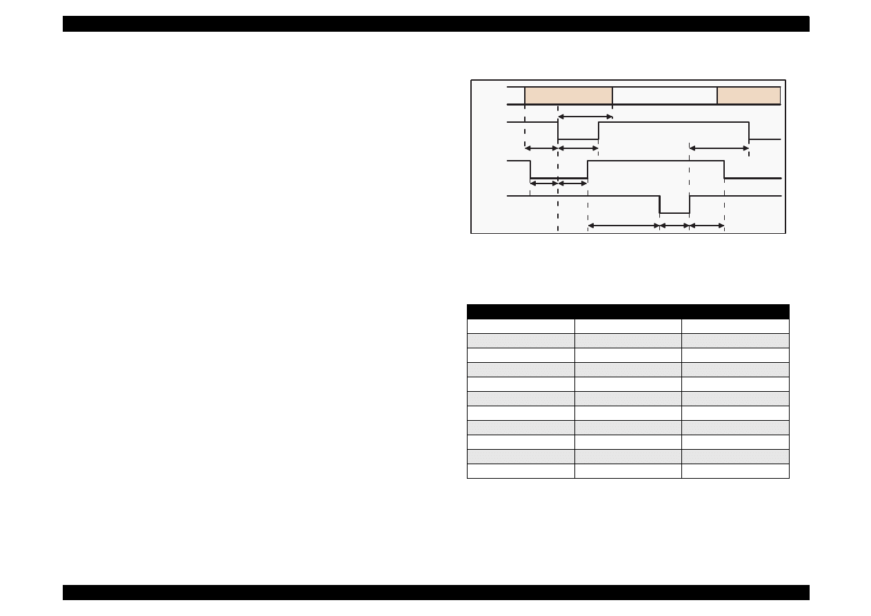
NOTE 3:Refer to Figure 1-9 for transmission timing of each signals.
NOTE 4:Do not perform data transmission ignoring /ACK or BUSY
signal. (Perform the data transmission after confirming that /
ACK and BUSY signals are Low.)
NOTE 5:It is possible to perform the printing test including interface circuit
without using equipment from outside when 8-bit data signal
(20-27 pin) is set to appropriate word code and connect them
forcefully to /ACK and /STRB.
Figure 1-9. Data Transmission Timing for Forward Channel
Table 1-13.
Maximum and Minimum Timing for Data Transmission
* Rise and fall time of every output signal.
** Rise and fall time of every input signal. Typical timing for the tack
parameter is shown below.
Parameter
Minimum
Maximum
tsetup
500ns
---
thold
500ns
---
tstb
500ns
---
tready
0
---
tbusy
---
500ns
tt-out*
---
120ns
tt-in**
---
200ns
treply
0
---
tack
500ns
10us
tnbusy
0
---
tnext
0
---
Byte Data n
Byte Data n+1
Thold
Tsetup
Tstrb
Tnext
Tready
Tbusy
Treply
Tack
Tnbusy
Data
/STROBE
BUSY
/ACKNLG
EPSON Stylus Color 440/640/740
Revision A
Chapter 1
Product Description
30
Table 1-14. Typical Tack Timing
Table 1-15. Signal level for TTL (IEEE-1284 level 1 device)
NOTE: A low logic level on the Logic H signal is 2.0V or less when the printer is
powered off and this signal is equal or exceeding 3.0V when the printer is
powered on. The receiver shall provide an impedance equivalent to 7.5K ohm
to ground.
1.3.2.1 Prevention Hosts from Data Transfer time-out
Generally, hosts abandon data transfer to peripherals when a peripheral
is in the busy state for dozens of seconds continuously. To prevent
hosts this kind of time-out, the printer receives data very slowly, several
bytes per minute, even if the printer is in busy state. This showdown is
started when the rest of the input buffer becomes several hundreds of
bytes. Finally, the printer is in the busy state continuously when the
input buffer is full.
1.3.2.2 Auto Interface Selection (for Stylus Color 640, 740)
Manual Selection:
One of two interfaces can be selected by the default setting mode.
Automatic Selection:
The automatic interface selection is enabled by the default setting
mode. In this automatic interface selection mode, the printer is
initialized to the idle state scanning which interface receives data
when it is powered on. Then the interface that receives data first is
selected. When the host stops data transfer and the printer is in the
stand-by state for the seconds, the printer is returned to the idle
state. As long as the host sends data or the printer interface is busy
state, the selected interface is let as it is.
Following explains conditions of other interfaces when a particular
interface is selected.
When the parallel interface is not selected, the interface gets
into BUSY state. At this time, LH signal is set to “L”. That means
blocking power supply and no responds from 1284. Therefore, it
is necessary for the host, which requires Reverse transfer, to
check LH state.
When the serial interface is not selected, the interface sets the
DTR signal MARK.
When the printer is initialized or returned to the idle state,
Parallel interface becomes the ready condition and DTR of serial
interface becomes SPACE (Low) condition and reset off-line bit
of Main Status Register (MNSTS)to, option interface.
Parallel I/F Mode
Typical Tack Timing
High speed
2us (for Stylus Color 440,640)
1us (only for Stylus Color 740)
Normal speed
4us (for Stylus Color 440,640)
3us (only for Stylus Color 740)
Parameters
Minimum
Maximum
COndition
VOH*
---
5.5V
VOL*
-0.5V
---
IOH*
---
0.32mA
VOH = 2.4V
IOL
---
12mA
VOL = 0.4V
CO
---
50pF
VIH
---
2.0V
VIL
0.8V
---
IIH
---
0.32mA
VIH = 2.0V
IIL
---
12mA
VIL = 0.8V
CI
---
50pF
EPSON Stylus Color 440/640/740
Revision A
Chapter 1
Product Description
31
1.3.3 Serial Interface (for Stylus Color 640, 740)
[Standard]
Based on RS-423
[Synchronization]
Synchronous
[Bit Rate]
Approx.1800Kbps
[Handshaking]
X-ON/X-OFF, DTR Protocol
[Word Format]
Data Bit= 8 bits
Parity Bit= None
Start Bit= 1 bit
Stop Bit= 1 bit
[Connector]
8-pin mini-circular connector
[Recommended Cable]Apple System Peripheral-8 Cable
Table 1-16. Pin Assignment
Table 1-17. X-On/X-Off and DTR Status
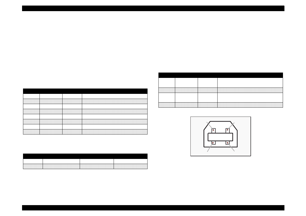
1.3.3.1 USB Interface (Only for Stylus Color 740)
[Standard]
Universal Serial Bus Specifications Rev. 1.0
Universal Serial Bus Device Class Definition
for Printing Device Version 1.0
[Bit Rate]
12 M bps
[Data Encoding]
NRZI
[Connector]
USB Series B
[Recommended Cable Length]
2 meters
Table 1-18. Pin Assignment
Figure 1-10. USB Pin Assignment
Pin No.
Signal Name
I/O
Description
1
SCLK
O
Synchronous clock signal
2
CTS
I
Clear To Send
3
TXD-
O
Transmit Data (-)
4
SG
I
(Signal Ground)
5
RXD-
I
Receive Data (-)
6
TXD+
O
Balanced Transmit Data (+)
7
DTR
O
Data Terminal Ready
8
RXD+
I
Balanced Receive Data (+)
State
Buffer Space
X-ON/X-OFF
DTR
Busy
Less than 3072 bytes
Send X-OFF code
OFF
Ready
More than 5120 bytes
Send X-ON code
ON
Pin No.
Signal Name
I/O
Description
1
Vcc
----
Cable power, Maxi. power consumption
is 100 mA
2
-Data
Bi-D
Data
3
+Data
Bi-D
Data, pull up to +3.3 V via 1.5 K ohms
resistor
4
Ground
----
Cable Ground
Pin #1
Pin #2
Pin #3
Pin #4
EPSON Stylus Color 440/640/740
Revision A
Chapter 1
Product Description
32
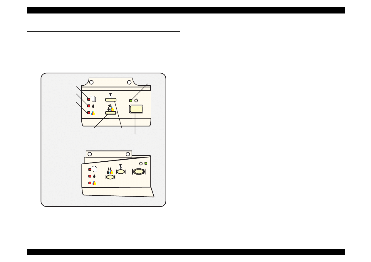
1.4 Control Panel
Since Stylus Color 440, 640, 740 does not require many buttons since
printer driver can start various settings and motions. Therefore, there
are only 2 non-lock type push switches, 1 lock type push switch and 4
LEDs. Figure 1-11 shows control panel of Stylus Color 440/640/740.
Figure 1-11. Control Panel Over Viewing
1.4.1 Indicators (LEDs)
(1) Power
Lights when the operate switch is “ON”, and AC power is supplied.
(2) Paper out
Lights during the paper-out condition, and blinks during the paper-
jam condition.
(3) Ink Out (Black)
Lights during no Black ink condition, and blinks during the Black
ink low condition.
(4) Ink Out (Color)
Lights during no Color ink condition, and blinks during the Color ink
low condition.
Paper Out LED
Ink Out(Bk)LED
Ink Out(CMY)LED
Power LED
Cleaning Switch
(Ink maintenance)
Load/Eject Switch
Power on Switch
Stylus Color 440, 640
Stylus Color 740
EPSON Stylus Color 440/640/740
Revision A
Chapter 1
Product Description
33
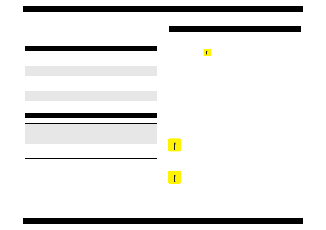
1.4.2 Panel Functions
Refer to Table 1-19 to Table 1-21.
Table 1-19. Panel Functions
Table 1-20. Panel Function with Power On
NOTE 1:You can check the 1) firmware version, 2) protection counter
and 3) nozzle check pattern by performing this function.
NOTE 2:The code pages for Stylus Color 440, 640 are not opened.
NOTE 3:Since Stylus Color 740 have 2 specifications both the standard
and NLSP version, user can select some parameter and a
character table by communicating with the printed list.
NOTE 4:After you enter this EEPROM reset mode, go to Table 1-21.
Table 1-21. EEPROM Reset
NOTE 5:Before you press the Load / Eject switch, be sure to enter the
EEPROM reset mode, referring to Table 1-20.
Switch
Function
Load/Eject
(within 2 sec.)
1. Loads or ejects a paper.
2. When the carriage is on the I/C replacement position, return
the carriage to the capping position.
Load/Eject
(for 2 sec.)
1. Starts the I/C replacement sequence.
Cleaning
(for 2 sec.)
1. Starts the printhead cleaning sequence.
2. In case it’s in the ink low or ink out condition, starts the I/C
replacement sequence.
Cleaning
(within 2 sec.)
1. When carriage is on the I/C replacement position, return the
carriage to the capping position.
Switch
Function
Load/Eject
1) Starts the status print.
(*1)
Cleaning
<Stylus Color 440, 640>
Changes the code page.
(*2)
<Stylus Color 740>
Enters the Default setting mode.
(*3)
Load/Eject
+
Cleaning
Enters the EEPROM Reset mode. (The Load/Eject LED blinks
for a few seconds.)
(Used only for resetting the maintenance error.)
(*4)
Switch
Function
Cleaning
Resets the EEPROM.
(*5)
1. While the Load/Eject LED is blinking (for about 2 seconds),
press down the Cleaning switch for 10 seconds.
The following steps vary depending on the printer.
2.
[Stylus Color 440/640]
After 10 seconds, both Bk and CMY ink LEDs come
ON
simultaneously.
[Stylus Color 740]
After 10 seconds, Load/Eject, Bk and CMY ink LEDs all
blink
simultaneously.
3.
[Stylus Color 440/640]
Confirming the both LEDs are
ON
, release the Cleaning
switch. The printer automatically starts initialization
operation to reset the specified addresses in the EEPROM.
[Stylus Color 740]
Confirming all 3 LEDs are
blinking
, release the Cleaning
switch. The printer automatically starts initialization
operation to reset the specified addresses in the EEPROM.
C A U T I O N
You can reset the below addresses in a EEPROM by
performing the EEPROM Reset operation.
1. 1) Timer Counter (Power Off time) IC value
2. I/F selection returns to Auto
3. Protection Counter value
C A U T I O N
Even though you repeat the EEPROM reset operation,
it does not perform initialization but only resets the
EEPROM addresses. Wheater or not to permorm
initialization depends on the power off time monitored
by the timer IC.
C A U T I O N
EPSON Stylus Color 440/640/740
Revision A
Chapter 1
Product Description
34
1.4.3 Printer Condition and Panel Status
Table 1-22 shows printer condition and panel status. Since the table
shows various error status and also indicates printer status, it enables
you to find appropriate repair ways.
Table 1-22. Printer Condition and LED Status
Printer Status
Indicators
Priority
Power
Ink Out (Black)
Ink Out (CMY)
Paper Out
Power on condition
---
---
---
---
9
Ink Sequence mode
On
---
---
---
6
I/C replacement mode
Blink
---
---
---
5
Data processing
Blink
---
---
---
8
Paper out
Blink
---
---
On
4
Paper jam
---
Off
Off
Blink
3
No I/C, Ink out (bk)
---
On
---
---
7
Ink level low (bk)
---
Blink
---
---
7
No I/C, Ink out (CMY)
---
---
On
---
7
Ink level low (CMY)
---
---
Blink
---
7
Enters the EEPROM Reset
---
ON (for 3 seconds)
---
Maintenance Request
Blink
Blink
Blink
Blink
2
Fatal Error
Blink
On
On
Blink
1

EPSON Stylus Color 440/640/740
Revision A
Chapter 1
Product Description
35
1.5 Error Status
When following status occur, the printer goes to the error status and
stops taking data, setting the /ERROR signal in the interface as “Low”,
and Busy signal as “High”. At this time, the printer goes to non printable
status. Refer to Section 1.4.3 for more details of LED Panel indicators
during the various error status.
1.5.1 Ink Out
When the printer runs out the most part of the ink of any one color, it
warns ink-low and keeps printing. When the printer runs out the whole
ink of any one color, it stops printing and indicates ink-out error. User is
requested to install a new ink-cartridge in this state. A ink-cartridge once
taken out should never be used again. Re-installation of the cartridge
not filled fully upsets the ink level detection and may cause a serious
problem in the print head as a result.
The following explains the warning sign above.
[Step 1]
After the cartridge is once taken out, bubbles come in from the ink
supply hole located at the top of cartridge and are absorbed into the
head during printing. AS a result, the head is unable to discharge ink
properly. Also, inevitable entry of bubbles created during installation of
a new ink cartridge can be absorbed to ink itself since the ink in the
cartridge is deaerated during the production process. However, this
ability for absorption can last only about one hour after the cartridge is
installed.
[Step 2]
Even after the bubble absorbing ability described above stops, there is
problem about entering bubbles as long as the ink cartridge is installed
in the printer. However, if the ink cartridge which does not have
absorbing ability any more is once removed from the printer, new
coming bubbles into the cartridge will never disappear naturally. These
bubbles may cause not only printing malfunction but also thickening ink.
This thickened ink goes into the head and clogs ink path in the head or
nozzle and may cause serious head damage.
[Step 3]
As standard specification for Stylus Color 400, ink consumption counter
is reset when the ink cartridge is removed. If an ink cartridge is removed
and re-installed unnecessarily the value on the ink consumption monitor
which the user can check will be wrong and printer may keep printing
even though the ink cartridge is installed empty. This may cause head
damage.
1.5.2 Paper Out
When the printer fails to load a sheet after power on operation including
timer-cleaning is done and Load/Eject button on the FF command or
operation panel is pressed, it goes into a paper out error.
1.5.3 Paper Jam
When the printer fails to eject a sheet even after feeding motion is
completed or Load/Eject button on the FF command or operation panel
is pressed, it goes into a paper jam error.
C A U T I O N
Never use the ink cartridge that has been removed.

EPSON Stylus Color 440/640/740
Revision A
Chapter 1
Product Description
36
1.5.4 No Ink-Cartridge
Following reasons can be the causes when printer goes this error
mode.
1. When the printer is turned on for the first time. (This is a normal
error state and it returns to the normal state after installing an ink
cartridge according to the ink cartridge exchange operation.)
2. Ink cartridge exchange operation is done correctly. After the position
of carriage is moved by exchange operation, if the cleaning switch is
pushed without installing ink cartridge or if the carriage returns to
the home-position automatically without doing any operation, it is
considered as handling mistake. However, it returns to normal state
by performing ink exchange operation again and installing cartridge
correctly.
3. If “No ink-cartridge error” appears even after the ink cartridge is
installed, the printer must be something wrong and around the
sensor area in the carriage need to be repaired.
4. If sometimes printer can print normally but also sometimes “No ink-
cartridge error” appears, the printer must be something wrong.
(Same reason as above)
1.5.5 Maintenance Request
When the total quantity of ink wasted through the cleanings and flushing
reaches to the limit, printer indicates this error and stops. The absorber
in the printer enclosure is needed to be replaced with new one by a
service person. The ink quantity that is absorbed by the absorber
(waste ink pad) is monitored by the software counter as “total ink
counter”. This counter is added by point system and absorber’s
maximum ability is set at the following reference value.
Stylus Color 440 Maximum Counter Point:
21000 Point
Stylus Color 640 Maximum Counter Point:
19800 Point
Stylus Color 740 Maximum Counter Point:
40900 Point
NOTE: Since 1 point of counter point equals 0.02 ml, the actual ink
amount becomes;
Stylus Color 440 Maximum Ink Capacity:
420 ml
Stylus Color 640 Maximum Ink Capacity:
396 ml
Stylus Color 740 Maximum Ink Capacity:
818 ml
1.5.6 Fatal Errors
When the printer detects fatal errors such as carriage control error or
CG access error, it enters a fatal error mode, as described below.
1) Carriage control Error:
Parallel adjustment malfunction
Home-position malfunction
Timing belt tension malfunction, shortage of lubricant on the
carriage guide shaft, etc.
2) CG Access Error:
Short circuit, etc.

EPSON Stylus Color 440/640/740
Revision A
Chapter 1
Product Description
37
1.6 Printer Initialization
Stylus Color 440, 640, 740 have three kinds of initialization methods.
Following explains each initialization.
[1.Power-on initialization]
This printer is initialized when turning the printer power on, or printer
recognized the cold-reset command (remote RS command). When
printer is initialized, following action is performed.
(a) Initializes printer mechanism.
(b) Clears input data buffer.
(c) Clears print buffer.
(d) Sets default values.
[2.Operator initialization]
This printer is initialized when turning the printer power on again within
10 seconds from last power off, or printer recognize the /INIT signal
(negative pulse) of parallel interface. When printer is initialized,
following action is performed.
(a) Cap the printer head.
(b) Eject a paper.
(c) Clears input data buffer.
(d) Clears print buffer.
(e) Sets default values.
[3. Software initialization]
The ESC@ command also initialize the printer. When printer is
initialized, following action is performed.
(a) Clears print buffer.
(b) Sets default values.
1.7 Initialization Settings
Stylus Color 440, 640, 740 initializes following settings when the
initialization is performed. Also, if the user changes the settings in the
Panel setting mode, Default setting or Remote command setting, values
or settings which are possible to be stored are initialized as initialization
settings.
Page position:
Page heading location for current page
Line spacing:
1/6 inch
Right margin position: 80 lines
Left margin position:
First
line
Character pitch:
10CPI
Printing mode:
Text mode (Not Raster graphics mode)

EPSON Stylus Color 440/640/740
Revision A
Chapter 1
Product Description
38
1.8 Main Components
Stylus Color 440, 640, 740 have following major units. Also, it is one of
the major characteristics that the bottom of the Printer mechanism
serves as the Lower case at the same time. Each unit from 2) to 5) are
simply explained below:
1) Upper Case
2) Printer Mechanism
3) Main Control Board
Stylus Color 440:C206 Main-B Board, C255 Main Board
Stylus Color 640:C256 Main Board
Stylus Color 740:C257 Main Board
4) Power Supply Board
Stylus Color 440:C206 PSB/PSE Board
Stylus Color 640:C206 PSB/PSE Board
Stylus Color 740:C257 PSB/PSE Board
5) Control Panel Board
Stylus Color 440:C206 PNL Board
Stylus Color 640:C206 PNL Board
Stylus Color 740:C209 PNL Board
1.8.1 Printer Mechanism
Like the previous printer mechanism such as for Stylus Color 400, 600,
and Stylus Photo, one of the major characteristics of Stylus Color 440,
640, 740 is that the printers have no Engage/Disengage mechanism to
change between the pump mechanism and paper feeding mechanism.
In stead, this change-over control is done by the distinction between
turning direction of PF/Pump motor and position of present carriage
unit. Also, another major characteristic is that printhead is on unit
combining black and color.
EPSON Stylus Color 440/640/740
Revision A
Chapter 1
Product Description
39
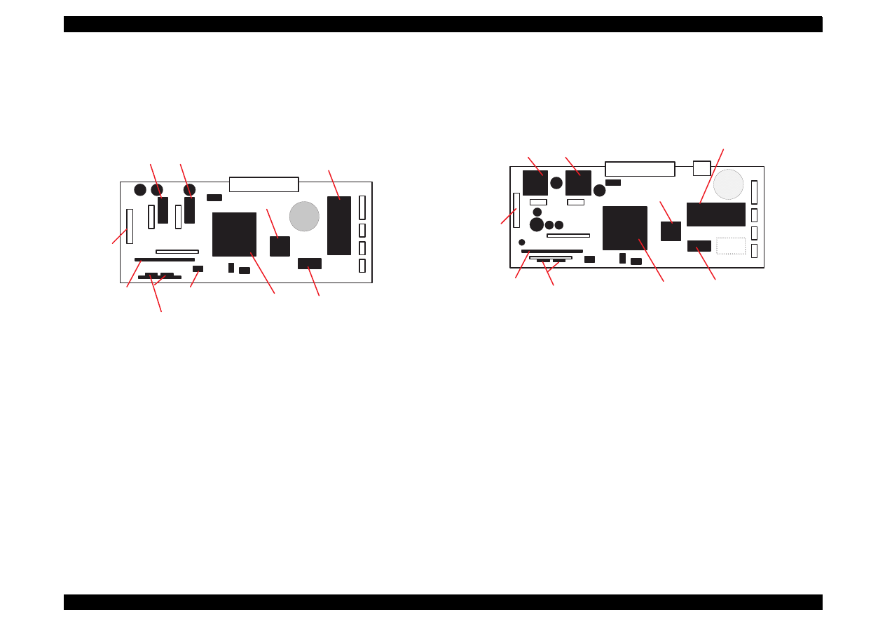
1.8.2 C206 Main-B Board (Stylus Color 440)
C206 Main-B board controls Stylus Color 440 and consists of following
major electric elements. This board will be changed to new board called
C255 Main board.
Figure 1-12. C206 Main-B Major Electric Elements
1.8.3 C256 Main Board (Stylus Color 640)
C256 Main board controls Stylus Color 640 and consists of following
major electric elements.
Figure 1-13. C256 Main Board Major Electric Elements
C N 1
B a t t 1
I C 7 ( H e a d )
C N 6
C N 7
I C 4 ( 4 M D - R A M )
I C 1 ( C P U )
I C 1 4 ( P F )
I C 1 5 ( C R )
I C 3 ( P - R O M )
I C 2 ( A s i c )
C N 1 0
Q 7 , Q 9 ( H e a d )
C N 8
E E P R O M
( I C 1 1 )
C N 3
C N 5
C N 4
C N 1 1
I C 1 4 ( P F )
I C 2 ( A s i c )
C N 1
C N 2
B a t t 1
I C 1 5 ( C R )
C N 1 0
I C 7 ( H e a d )
Q 7 , Q 9 ( H e a d )
C N 8
C N 6
C N 7
C N 3
C N 5
C N 4
C N 1 1
I C 1 6 ( P - R O M )
I C 6
I C 5 ( 4 M D - R A M )
I C 1 ( C P U )
EPSON Stylus Color 440/640/740
Revision A
Chapter 1
Product Description
40
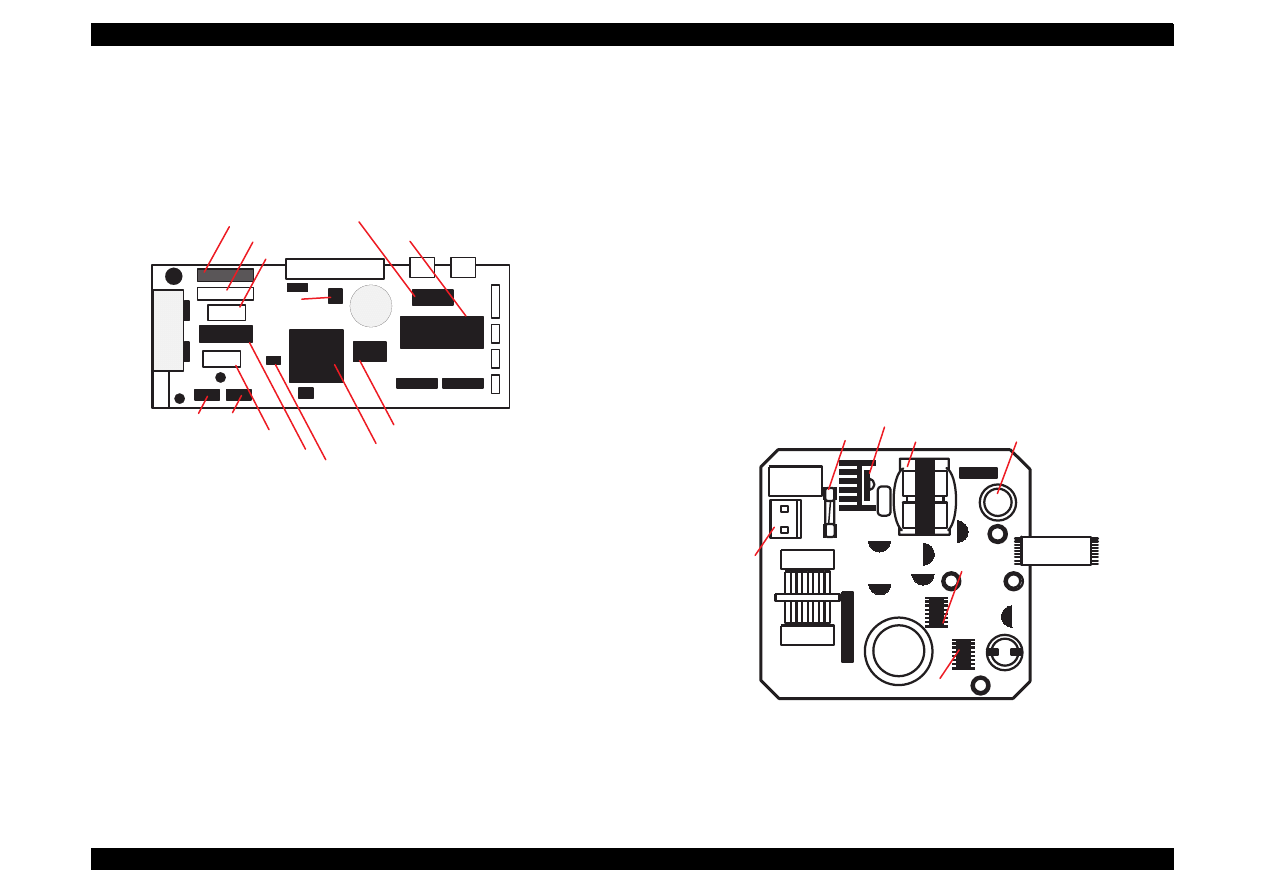
1.8.4 C257 Main Board (Stylus Color 740)
C257 Main board controls Stylus Color 640 and consists of following
major electric elements.
Figure 1-14. C257 Main Board Major Electric Elements
1.8.5 Power Supply Board
C206 PSB/PSE (Stylus Color 440, 640)
C257 PSB/PSE (Stylus Color 740)
In the electric boards for Stylus Color 440, 640, 740, a switching
regulator method is used and supplies stable logic and power voltages
constantly. Also, since this C206/C257 PSB board ha secondly type
switch for its circuit system, it is possible to keep supplying electricity to
the C206main-B/C255/C256/C257 main control board for 30 seconds
even after the power switch is turned off. Using this time difference,
even when mis-operation is done by the user such as turning off the
power during the middle of printing work, it prevents thickened ink from
attaching around the nozzle plate by transferring the head to cap
position.
Figure 1-15. C206/C257 PSB/PSE Board Major Electric Elements
H T 1
C N 9
C N 7
I C 1 4 ( H e a d )
C N 8
I C 1 1 ( C R )
I C 1 2
I C 1 3
I C 2 ( A s i c )
I C 1 ( C P U )
I C 3 ( P - R O M )
I C 6 ( C G : o n l y f o r N L S P )
B a t t 1
C N 1
C N 3 C N 2
I C 4
I C 5
( 4 M D R A M x 2 )
I C 7 ( E E P R O M )
( P F D r i v e )
I C 1 5
( R e g u r a t o r )
C N 3
C N 5
C N 4
C N 1 1
Fuse(F1)
Q1(FET)
Trans(T1)
C51
CN2
IC51
PC1
C11
Filter(L1)
CN1
EPSON Stylus Color 440/640/740
Revision A
Chapter 1
Product Description
41
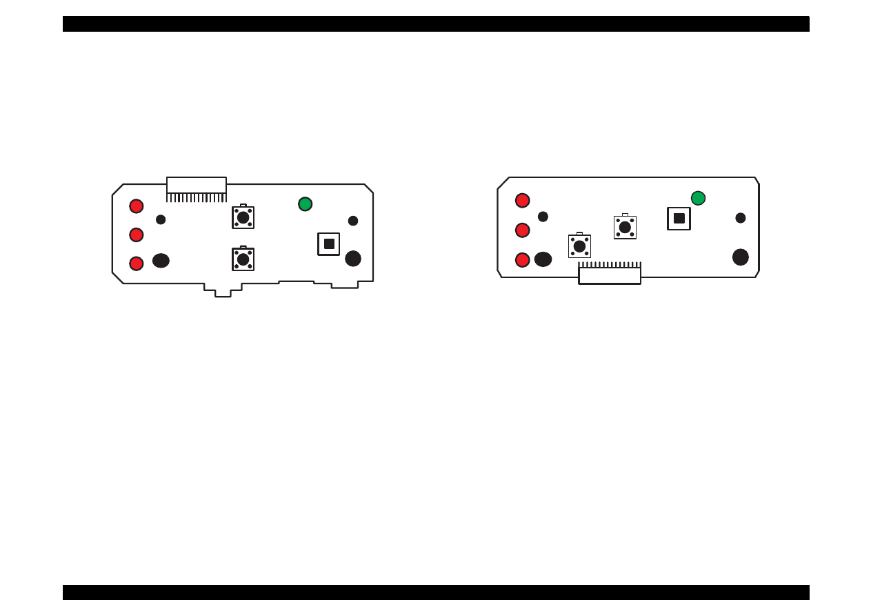
1.8.6 C206 PNL Board (Stylus Color 440, 640)
Panel board (C206 PNL board) is located in the panel case where is in
the right bottom of the front printer and consists of 3 switches, 4 LEDs
and 1 connector.
Figure 1-16. C206 PNL Board
1.8.7 C209 PNL Board (Stylus Color 740)
Panel board (C209 PNL board) is located in the panel case where is in
the right bottom of the front printer and consists of 3 switches, 4 LEDs
and 1 connector.
Figure 1-17. C209 PNL Board
SW0
SW2
SW1
LED4
LED0
LED1
LED2
CN1
SW0
SW2
SW1
LED4
LED0
LED1
LED2

OPERATING PRINCIPLES

EPSON Stylus Color 440/640/740
Revision A
Chapter 2
Operating Principles
43
2.1 Overview
This section describes the operating principles of the printer mechanism
and the electric circuit board.
Electronic Boards for Stylus Color 440 are;
Main:
C206 Main-B, C255 Main Board
Power Supply:
C206 PSB,PSE Board
Panel:
C206 PNL Board
Electronic Boards for Stylus Color 640 are;
Main:
C256 Main Board
Power Supply:
C206 PSB,PSE Board
Panel:
C206 PNL Board
Electronic Boards for Stylus Color 740 are;
Main:
C257 Main Board
Power Supply:
C257 PSB,PSE Board
Panel:
C209 PNL Board
EPSON Stylus Color 440/640/740
Revision A
Chapter 2
Operating Principles
44
2.1.1 Printer Mechanism
Like previous EPSON Ink Jet printers such as Stylus Color 400, 600,
Photo, Photo 700, Photo EX, the printer mechanism of Stylus Color
440/640/740 does not have an exclusive mechanism to change over
paper feeding and pumping operation. In stead, this control is done by
the turning direction of paper feed/pump motor and position of the
carriage at that time. Also, the print heads of these printers combine the
black and CMY heads in one unit. The followings indicate the nozzle
configurations of these 3 models.
Stylus Color 440:
Black Nozzle:
64 nozzles(90 dpi x 2 rows in staggered)
CMY Nozzle:
21 nozzles/colors(90 dpi x 1 row)
Stylus Color 640:
Black Nozzle:
64 nozzles(90 dpi x 2 rows in staggered)
CMY Nozzle:
32 nozzles/colors(90 dpi x 1 row)
Stylus Color 740:
Black Nozzle:
144 nozzles(120 dpi x 3 rows in staggered)
CMY Nozzle:
48 nozzles/colors(120 dpi x 1 row)
Among these printers, the Stylus Color 640 and 740 can print 1440 (H)
x 720(V) resolution like Stylus Color 800 and Pro5000. On the other
hand, the Stylus Color 440 can print real 720 dpi(720 (H) x 720(V))
resolution like Stylus Pro XL.
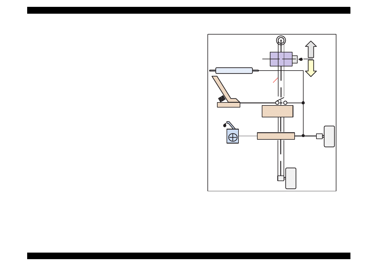
Figure 2-1 in the in the right column shows the outline of the printer
mechanism.
Figure 2-1. Printer Mechanism Block Diagram
Carriage Motor
Paper Feed
Motor
Pump Position
Paper Load
Trigger Lever
Carriage Unit
(Print Head Unit)
Hopper
Drive
Pump
Drive
Timing
Belt
PF Roller Drive
EPSON Stylus Color 440/640/740
Revision A
Chapter 2
Operating Principles
45
2.1.1.1 Printing Mechanism
Basic principles of the print head which plays major role of printing
mechanism is the same as previous models; on demand type MACH
head method, but there is some difference in the resolution. (Refer to
figure1-1)
Also, unlike Stylus Color IIs, 820, 200 automatic correction type, in
order to fix the dispersion of mufti layer piezo electric element which is
used for driving each nozzles, it is necessary to input the VH value
written on the side of print head by using exclusive program when you
replace print head, control board, or the printer mechanism.(However,
there are no resistor array to decide the VH voltage on the main control
board.) Following explains print head.
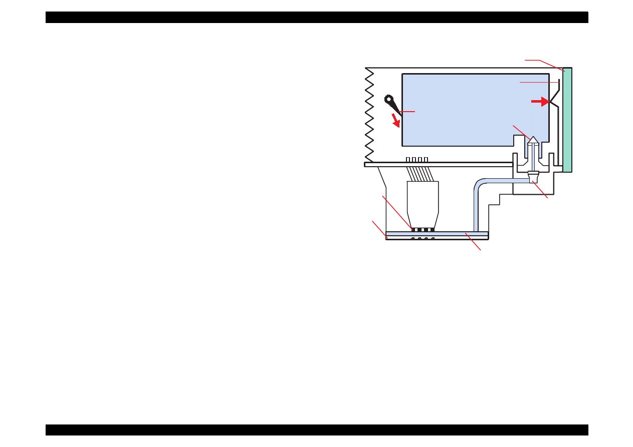
PZT
PZT is an abbreviation of Piezo Electric Element. Print signal from
the PSB/PSE board is sent through the driver board on the print
head unit and to the PZT. Then, the PZT pushes the top cavity
which has ink stored, and make the ink discharge from each nozzle
located on the nozzle plate.
Cavity Set
Ink which is absorbed from ink cartridge go through the filter and will
be stored temporarily in this tank, which is called “cavity” until PZT is
driven.
Nozzle Plate
The board with nozzle holes on the printer head surface is called
Nozzle Plate.
Filter
When the ink cartridge is installed, if any dirt or dust around the
cartridge needles are absorbed into the head inside, there is a great
possibility of causing nozzle clog and disturbance of ink flow and
finally causing alignment failure and dot-missing. In order to prevent
this, filter is set at cartridge needle below and ink is once filtered
here.
Figure 2-2. Print Head Sectional Drawing
I/C Sensor's actuator
Stylus Color 440,640
I/C Sensor's actuator
Stylus Color 740
(Ink Cartridge)
Nozzle Selector Board
Needle
Nozzle Plate
PZT
Cavity
Filter
EPSON Stylus Color 440/640/740
Revision A
Chapter 2
Operating Principles
46
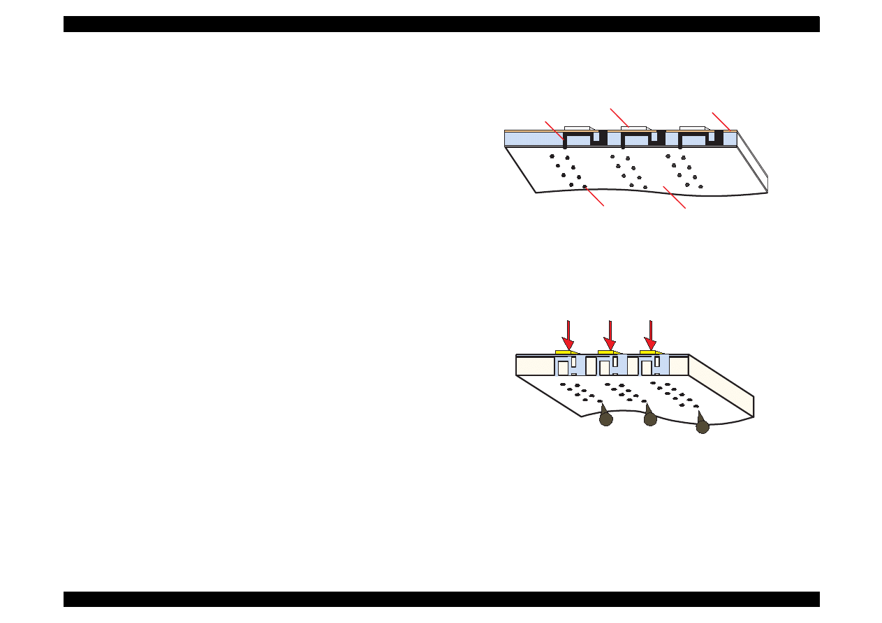
2.1.1.2 Printing Process
Following figures show the sectional drawings of normal state and
ejecting state of the printhead.
1. Normal State:
When the print signal is not output, PTZ also does not move in the
waiting state (normal state). (Refer to Figure 2-3.)
2. Ejecting State:
When the print signal is output from the C206 main-B/C255/C256/
C257 main board, IC (IR2C72C:Nozzle Selector) located on the
Print head unit latches the data once by 1-byte unit. Appropriate
PZT latched by nozzle selector is pushed into the cavity by applying
common voltage from the main board. By this operation, ink that is
stored in the cavity pops out from nozzles. (Refer to figure 2-4.)
Figure 2-3. Print Head Normal State
Figure 2-4. Print Head Ejecting State
Nozzle
Nozzle Plate
Cavity
PZT
Ink Course
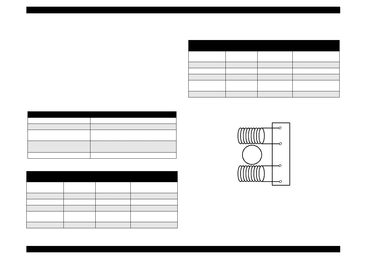
EPSON Stylus Color 440/640/740
Revision A
Chapter 2
Operating Principles
47
2.1.1.3 Carriage Mechanism
Carriage mechanism is to drive the carriage with print head mounted
from left to right or vice versa. The carriage drive motor in these printers
are a 4-phase, 200-pole, stepping motor and is driven by 1-2 phase, 2-2
phase and W1-2 phase drive method for Stylus Color 440, 460, and by
2-2 phase 1-2 phase, W1-2 phase, 2W1-2 phase and 4W1-2 phase
drive method for Stylus Color 740. This stepping motor allows the
carriage to move freely to
the particular positions which is necessary for various operation, such
as paper feeding, ink absorbing, flashing, ink exchange and cleaning
operations. The tables below show carriage motor specifications and
motor controls at each mode.
Table 2-1. Carriage Motor Specifications
Table 2-2. Motor Control at Each Modes (Stylus Color 440, 640)
Table 2-3. Motor Control at Each Modes (Stylus Color 740)
Figure 2-5. CR (PF) Motor Internal Circuit Diagram
Items
Description
Motor type
4-Phase/200-pole Stepping motor
Drive voltage Range
42VDC
±
5%
Internal coil resistance
7.8 Ohms
±
10%(per phase under 25
°
C
environment)
Driving Speed(frequency)
Range[csp(Hz)]
5(60)
∼
340(4080)
Control method
Bi-Pola Drive
Printing mode
Drive Speed
[CPS]
Drive frequency
[PPS]
Drive method
High Speed Skip
340
4080
W1-2, 2-2,1-2
phase drive*
Normal Printing
200
2400
W1-2, 2-2 phase drive
Capping
80
960
W1-2, 2-2 phase drive
Wiping
40
480
W1-2, 2-2 phase drive
Cap
(Valve Release)
20
240
W1-2, 2-2 phase drive
Withdrawal of cap
5
60
W1-2, 2-2 phase drive
Printing mode
Drive Speed
[CPS]
Drive frequency
[PPS]
Drive method
High Speed Skip
340
4080
W1-2, 2-2,1-2
phase drive*
Normal Printing
200
2400
W1-2, 2-2 phase drive
Capping
80
960
2W1-2, 2-2 phase drive
Wiping
40
480
2W1-2, 2-2 phase drive
Cap (Valve
Release)
20
240
4W1-2, 2-2 phase drive
Withdrawal of cap
5
60
4W1-2, 2-2 phase drive
Rotor
1
2
3
4
A
/A
B
/B
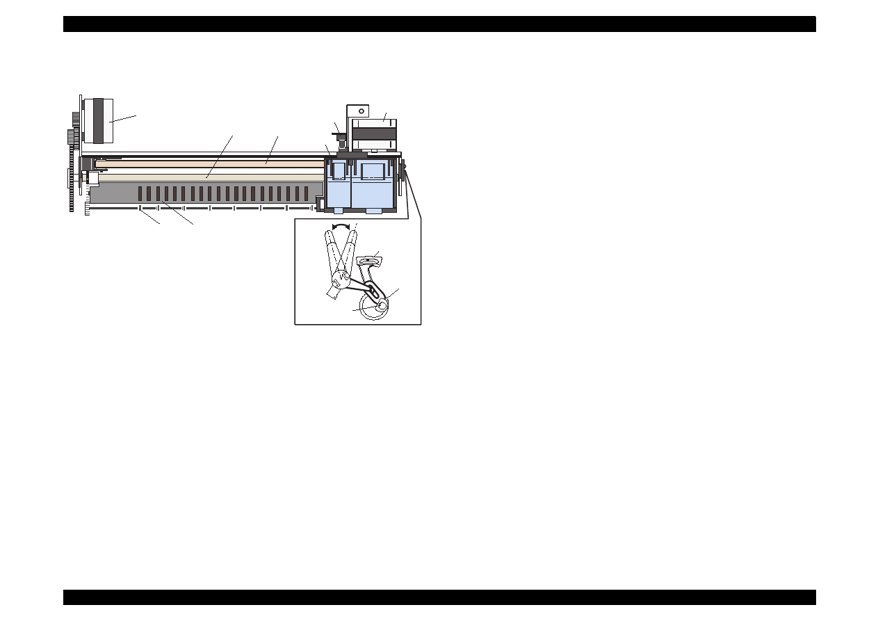
EPSON Stylus Color 440/640/740
Revision A
Chapter 2
Operating Principles
48
See Figure 2-6 which shows the carriage mechanism.
Figure 2-6. Carriage Mechanism (Top view)
The printhead, a core of the printing mechanism, is stored in the
carriage unit. When the adjustment lever is moved up and down, this
printhead maintains the printhead tilt in a flexible and adjustable
structure, using a tilt adjustment mechanism. Also, the parallelism
adjustment lever, mounted on the left and right sides of the carriage
guide shaft, adjusts parallelism between the platen and shaft when the
shaft is installed to the printer mechanism. After this adjustment is
completed, moving PG adjustment lever changes space between the
platen surface and the print head surface to one of two possibilities:
either 1.04 mm or 1.74mm. It is possible to vary the space between
platen surface and print head by rotating the shafts of the carriage guide
shaft which itself is decentralized, with the operation of PG lever. This is
the mechanism that the user can use to adjust the appropriate PG value
according to the printing result or any other environmental conditions
such as paper curl.
Carriage lock mechanism is to prevent the carriage from being left at an
uncapped position for a long time because of vibration during the printer
transport or mishandling by the users. If the carriage is left uncapped for
long time, ink on the print head surface gradually becomes thick. As a
result, the nozzle will be unable to discharge ink.
To make matters worse, the holes (crater) of nozzle may be completely
clogged by the thick ink and it may not be able to return to the normal
condition just by cleaning operation. In order to prevent this, printer
goes to carriage lock state at the following conditions. (See the following
page.)
After Power OFF operation:
If the power is turned off on the way of printing or any other
performance, carriage lock will be performed in the end after
completing initialize operation.
After power ON operation:
After power is turned on and automatic P-On Cleaning is performed,
then carriage lock will be performed. P-On Cleaning is an automatic
head cleaning that is performed when the power is turned on. The
timer IC always calculates printer’s power OFF time by the power of
lithium battery mounted on the C206 Main-B/C255/C256/C257 Main
board. P-on cleaning function automatically selects the cleaning
level according to the time which the printer is not in
used.
After Eject the paper:
After Load/Eject button is pressed and the paper is ejected, if the
data is not input, the printer performs carriage lock and goes to
standby state. However, if the paper is loaded to the printer inside
by Load/Eject button, the printer does not perform carriage lock
operation.
Carriage home position Sensor
Carriage Motor
Timing Belt
PF Roller
Paper Feed Motor
Eject Roller
Paper guide(Front)
Carriage Unit
Front Side
Rear Side
Parallelism
Adjust Lever
Carriage
Guide Shaft
Fixing Bush
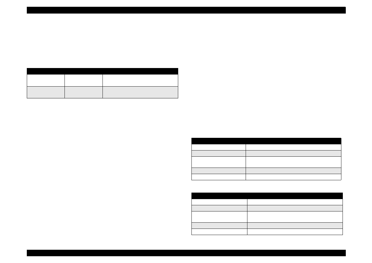
EPSON Stylus Color 440/640/740
Revision A
Chapter 2
Operating Principles
49
2.1.1.3.1 Platen Gap Adjust Mechanism and Parallel adjustment
Mechanism
This mechanism can be set by the users and can prevent various
problems related to low image density or print with any dirt by changing
the positions of PG lever according to the paper types.
Table 2-4.
Platen Gap Adjust Lever Setting
It is a major premise that parallel adjustment is done correctly for the
space between head and platen (PG adjustment value above) which
can be changed by platen gap adjustment. Parallel adjustment should
be done when the serviceman mounts the carriage guide shaft on the
printer mechanism during the production process or repair service. In
the adjustment, the space between parallel adjustment lever and gage
should be 1.04 mm.
2.1.1.4 Paper Feed Mechanism and Pump Mechanism
Mechanisms that send the paper in the hopper to inside the printer and
perform constant paper feed in order to perform printing on the sent
paper are called paper feed mechanism as generic name. In the Stylus
Color 440/640/740, 4 phase hybrid type pulse motor is used in the PF
motor as a motive power motor as a motive power of the paper
mechanism and driving is done at 2-2, 1-2 phase drive method for
Stylus Color 440, 640 and at 2W1-2, W1-2, 1-2 and 2-2 phase drive
method for Stylus Color 740. This motor is not only used as a power
source for paper feed mechanism but also used as power source of
pump mechanism which is necessary for print head cleaning. By using
this pulse motor, it becomes possible to use high speed driver or
intermittent drive for the various paper feeds and pump operations such
as paper feed, slight paper feed, high and low speed absorption of
pump operations. Following tables show PF motor specifications and
control method at each mode.
Table 2-5.
PF Motor Specifications (Stylus Color 440, 640)
Table 2-6. PF Motor Specifications (Stylus Color 740)
Paper
Lever Position
PG adjustment value
All Media
Front
0 mm
(1.04mm between head and platen)
If you find any print
problems
Rear
0.7mm
(1.07mm between head and platen)
Item
Description
Motor type
4-phase/48-pole Stepping motor
Drive voltage
42VDC
±
5%
Coil Resistance
7 Ohms
±
10%(per 1 phase under 25
°
C
environment)
Drive frequency [Hz]
100-1990 Hz
Control method
Bi-Pola Drive
Motor type
4-phase/200-pole Stepping motor
Drive voltage
42VDC
±
5%
Coil Resistance
8.8hms
±
10%(per 1 phase under 25
°
C
environment)
Drive frequency [Hz]
100-3240 Hz
Control method
Bi-Pola Drive
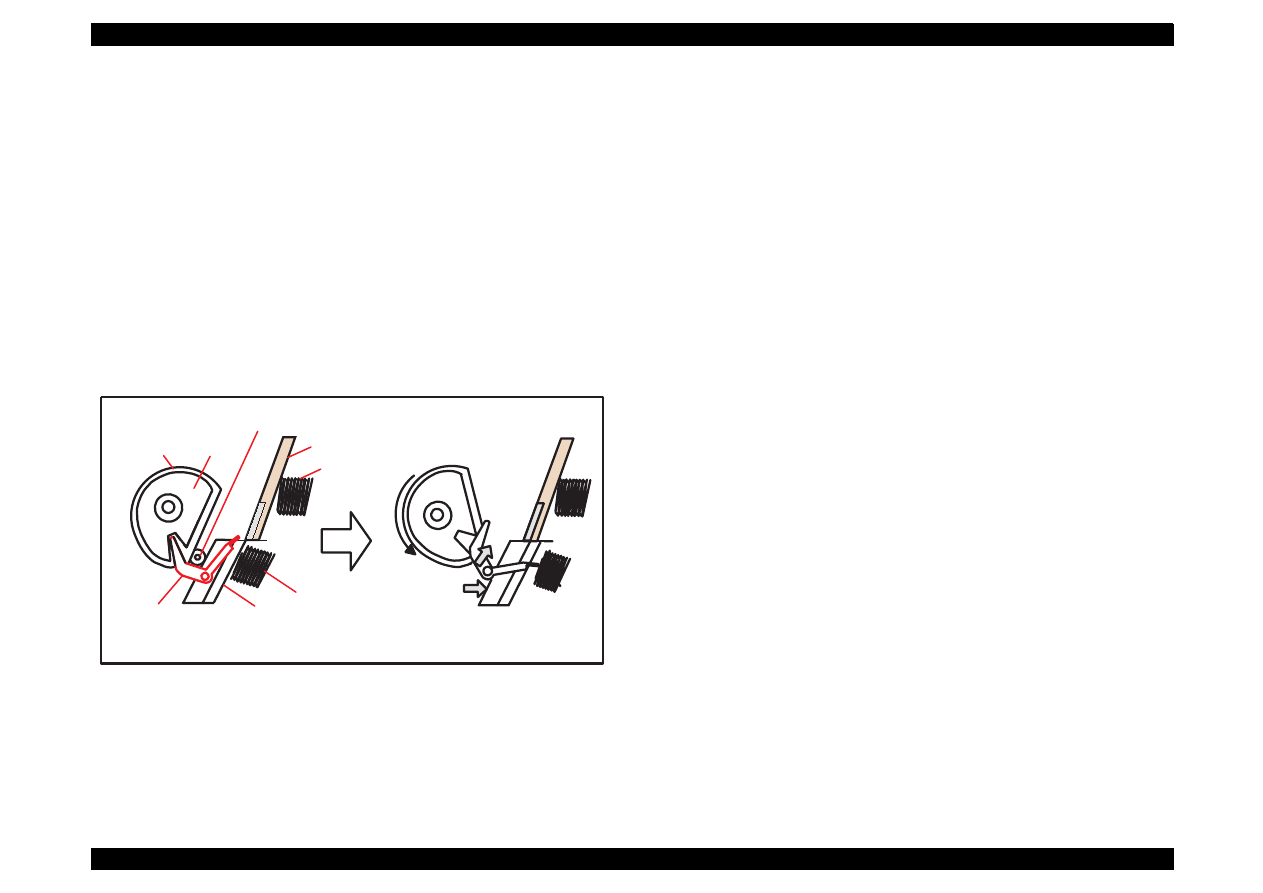
EPSON Stylus Color 440/640/740
Revision A
Chapter 2
Operating Principles
50
Papers on the ASF (auto-sheet-feeder) supplied by the user are carried
to the printer inside by paper pick up sequence. Unlike the previous
models, ASF of Stylus Color 440/640/740 has mufti feed prevention
mechanism. Following explains this function and figure below shows its
mechanism.
[1. Multi-feed prevention mechanism]
When the Load/Eject button is pressed, reversed rotation of PF motor is
performed. The return lever resets papers which are already in the out
of stand by position in the stand by position and make it possible to
perform stable paper feeding by picking up the paper again. Following
explains process of multi-feed prevention step by step. Refer to the
figure above and confirm its operation.
Figure 2-7. ASF Unit Operation
[Step 1]
When the load/Eject switch is pressed or printing order is input from
the PC, PF motor rotates counterclockwise and makes the CAM
rotate towards direction of 1 in the figure above.
[Step 2]
When the CAM covers the notch by the return lever, that position is
considered as home position, being monitored by ASF sensor.
[Step 3]
When the CAM rotates toward 1 in the figure above, the return lever
is pushed by the notch of CAM and falls towards 2. At this time, the
return lever moves to direction 3 by this motion, and push down the
pad which is waiting in the below part. At this time, friction of pinch
roller and pad will be canceled.
[Step 4]
The papers which are out of stand by position by the previous paper
feed motion are returned to the paper stand by position by flip over
strength of return lever. After this, PF motor rotates clockwise and
the printer goes to pick up sequence.
In the paper pick up mechanism of Stylus Color 440/640/740, same
mechanism as Stylus Color 400, 600, Photo, Photo EX are applied. This
mechanism changes adjoined lines of gear by colliding trigger lever with
carriage unit and convey the motive power on the platen to the ASF side
(paper roller). The figure below shows mechanism with explanation.
Return Lever
Pad spring
Hopper spring
Hopper
Pintch Roller
D-Cut Roller
CAM
[Standby state]
[Returning state]
1)
2)
2)
Pad
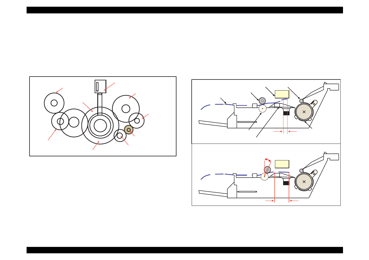
EPSON Stylus Color 440/640/740
Revision A
Chapter 2
Operating Principles
51
[2. Paper pick up mechanism]
When the Load/Eject switch is pressed or printing order is input, the
carriage unit moves until the left edge and collides with paper pick up
trigger lever. When the carriage collides with this trigger level, a
planetary gear located on the same axis is also pushed at the same
time and conveys the motive power on the platen to the adjoined gear
line side for ASF drive.
Figure 2-8. Paper Pick up Mechanism
[3. Paper feed mechanism]
After papers in the ASF receive controls from pick up and multi feed
prevention mechanism, they are sent to the printer inside. The papers
picked up by paper roller in the ASF goes to between platen and roller
support. Also, the eject roller pushes out the paper completely until the
end and the roller support drops the paper in the eject tray. The eject
roller is driven with an eject paper notched roller as pair where is
located on the paper eject roller.
Paper eject notched roller solves the deflection of paper that is in the
between platen eject notched roller and paper eject roller and always
keep a certain space between print head and paper surface. For an
unique point, the securing angle of Eject Notched Roller has been
changed by 5 degrees compared with the previous products. Due to this
change, the bottom margins of these printers are expanded from 14 mm
to 3 mm.
Figure 2-9. Paper Feed Mechanism
ASF Roller Drive Gear
Planetary Gear
ASF Roller Transmission Gear
Platen Roller Drive Gear
Platen Roller Transmission Gear
PF Motor Pinion Gear
Eject Roller
Transmission Gear
Eject Roller Drive Gear
Paper Pick Up
Trigger Lever
Eject Notched Roller
Eject Roller
PF Roller
Support Roller
Paper
Print Head
Bottom Margin 3 mm
Touch on the print head surface.
[Previous]
[Stylus Color 440,640,740]
Platen
Steady
5 degrees
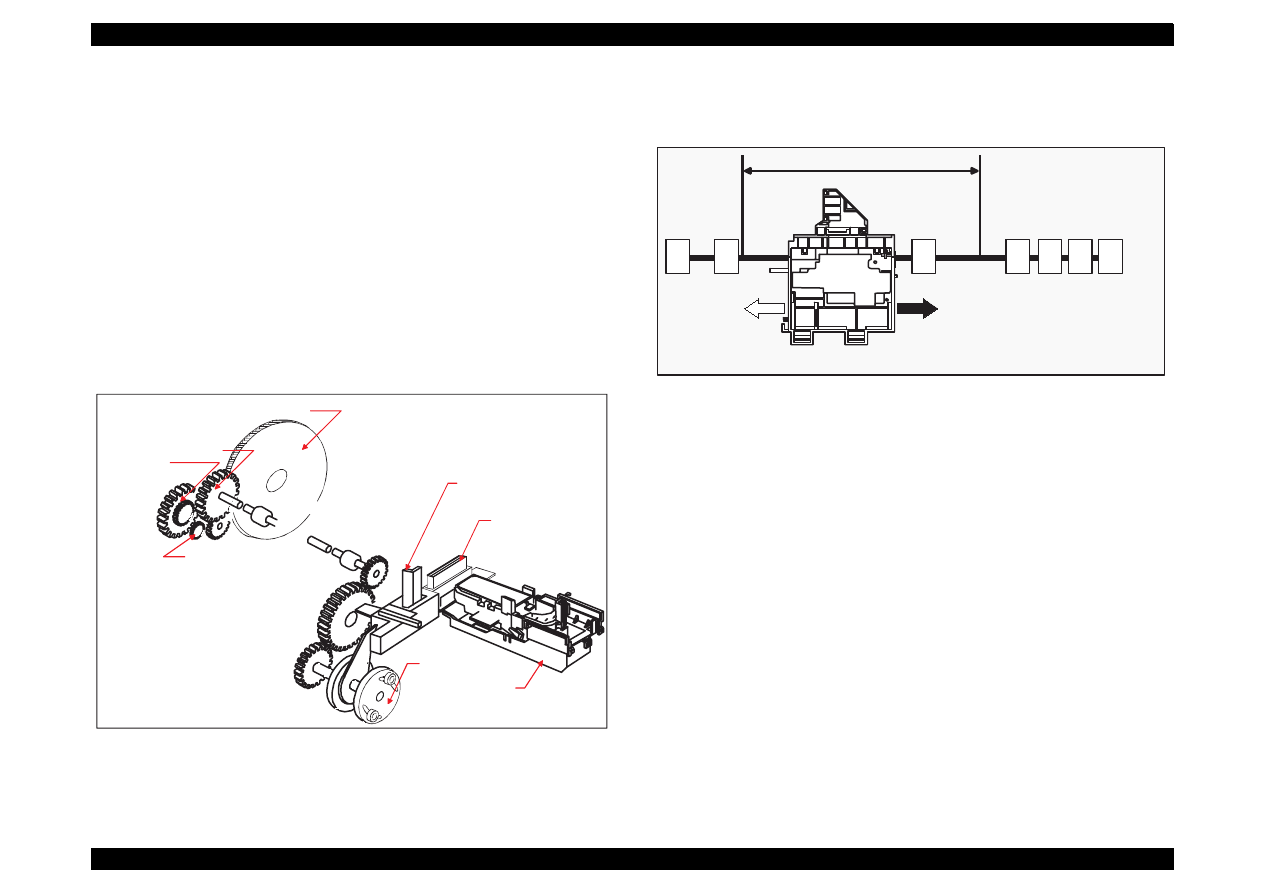
EPSON Stylus Color 440/640/740
Revision A
Chapter 2
Operating Principles
52
2.1.1.5 Ink System
Ink system mechanism consists of 1)cap mechanism, 2)pump
mechanism, carriage lock mechanism, 4)waste ink absorber and 5)ink
sequence. Out of these mechanism, from 1) to 4) are physical
mechanism and parts which are mounted on the printer mechanism and
5) ink sequence is performed automatically by firmware. Also, unlike
previous models, since Stylus Color 440/640/740 has no engage/
disengage mechanism to change over pump mechanism and paper
feed mechanism, it is one of the major characteristics that pump and
platen are always at work whenever the PF motor is driven. The figure
below shows head positions when the ink system and various ink
sequence are performed.
Figure 2-10. Ink System Mechanism
Figure 2-11.
Major Ink Sequence Position on Carriage Working Area
PF Roller Drive Gear
Eject Roller
Drive Gear
Eject Roller
TransmissionGear
PF(Pump) Motor
Pinion Gear
Pump Roller
Cap Unit
Cleaner Blade
Carriage Lock Lever
A
B
C
D
E
F
G
Printable Area
2976 dot(360-dpi)
A: Dummy Pumping Position(CRHP)
B: Ink Dischage Position
C: Flashing Position
D: Wiping Complete/Rubbing start Position
E: I/C Replacement Position
F: ASF Pick up Position
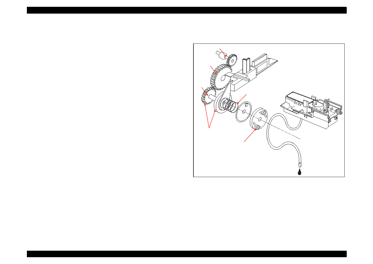
EPSON Stylus Color 440/640/740
Revision A
Chapter 2
Operating Principles
53
2.1.1.6 Pump, Carriage Lock, Head Cleaner Mechanism
In the Stylus Color 440/640/740, there is no switch or mechanism to
change over the pump/paper feed mechanism. Therefore, whenever
the paper feed/pump motor rotate, pump drive roller in the pump unit
inside rotates. However, ink absorption/non ink absorption are
separated by the roller rotational direction. Also, even if the pump driver
rotates toward ink absorption and the carriage position is in the false
absorption position, only driving in the pump mechanism is performed
and actual ink attraction is not done. Figure 5-2 shows process of
conveying motive power to the pump drive roller.
See Figure 1-12. The process of conveying the motive power to the
paper eject roller by rotating the pinion of PF motor is descried in figure
2-10. This motive power is conveyed to the Gear C through the Gear B.
In the figure above, although the lever in order to drive Gear C, carriage
lock, head cleaner mechanism is shown separately, it is constructed as
one unit. Since the engagement of these two parts depends on the
tension of the compression spring, if the lever is burdened, only Gear C
and pump roller rotate and no more motive power is conveyed to the
lever part.
Figure 2-12. Pump Mechanism Power Transmission Process
Axis of Paper
Eject Roller
Gear A
Gear B
Gear C
Actually, these parts
are one unit.
Compression
Spring
Pump Drive Roller
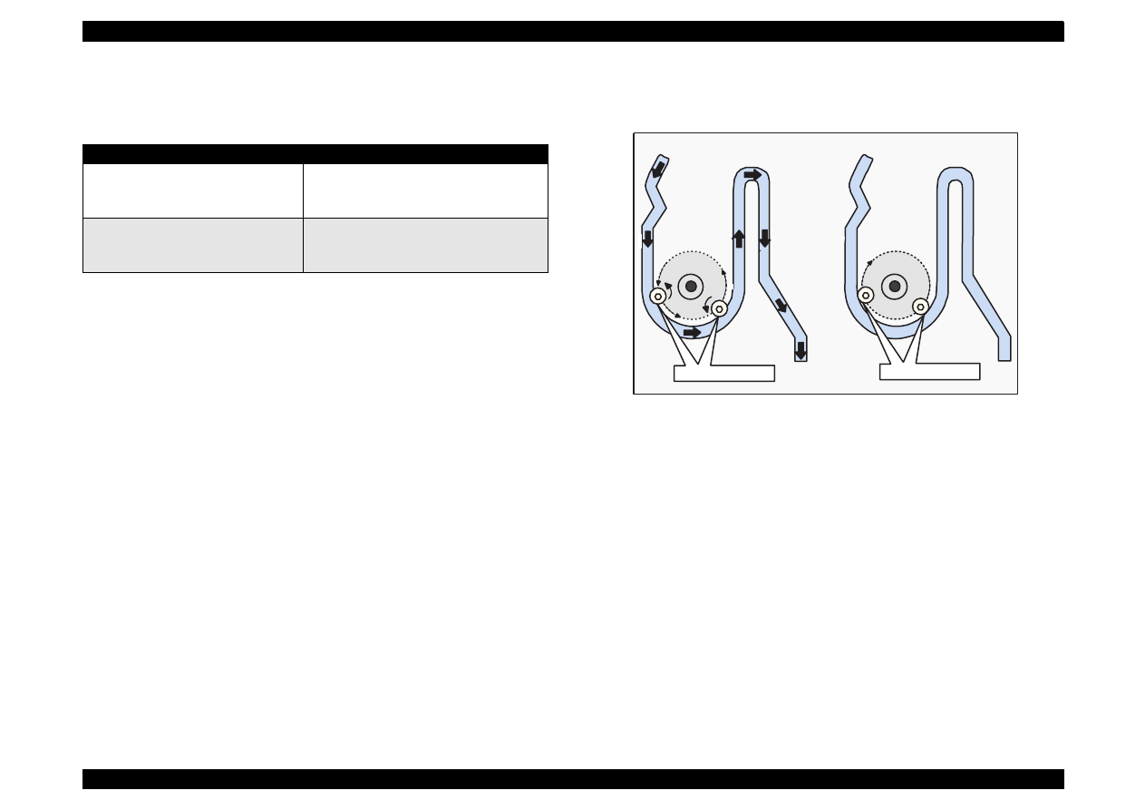
EPSON Stylus Color 440/640/740
Revision A
Chapter 2
Operating Principles
54
The table below shows PF/Pump motor rotational direction and pump
system operation.
Table 2-7.
Relationship between Pump Motor Rotation and it’s Work
Refer to Figure 1-13 in the right column which shows the pump
operations at clockwise and counterclockwise rotation.
In the ink absorptive operation such as cleaning, flushing and initial ink
charge except for printing operation, ink in the ink cartridge drains to the
waste ink absorber(pad) through the cap by the pump unit drive. In case
of printing and flashing drive, ink is popped out by the PZT in the print
head, but in case of absorptive operation such as cleaning and initial ink
charge, ink absorption is performed only by the pump drive without PZT
drive after the head surface is adhered to the cap. The next page
explains cap mechanism and relation between printer operation and
cap.
Figure 2-13. Pump Roller Rotation and it’s Operation
PF/Pump motor rotational direction
Pump unit operation
Clockwise (CW)
forward rotation
1)Release from the Pump pressure welding
2)Head cleaner reset
3)Carriage lock reset
Counterclockwise (CCW)
backward rotation
1)Rotation towards pump pressure welding
2)Head cleaner set
3)Carriage lock set
Tube pressured
Tube released
CW Rotation
CCW Rotation
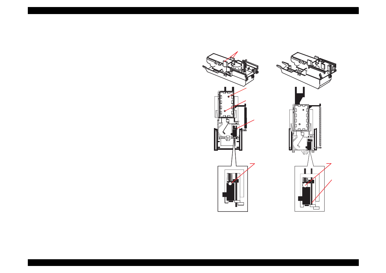
EPSON Stylus Color 440/640/740
Revision A
Chapter 2
Operating Principles
55
2.1.1.6.1 Cap Mechanism
In the cap mechanism, in order to prevent ink from being thickened on
the head surface, it is controlled that the head surface stays adherent to
the rubber frame of the cap surface when the power is off. The absorber
is spread in the cap and can hold a certain amount of ink which is
absorbed from the head without draining it to the waste ink pad. Also, in
the bottom of absorber, there are two valves in order to control
adhesion of head and cap surface, and one exit to drain ink to the waste
ink pad. If the carriage is out of HP (in this case, in the printable area or
paper feed position), the valves on the cap mechanism stays in the
position A in the figure above and are always closed. In this condition,
the carriage collides with flag, actual ink absorption and slight ink
absorption are performed. Also, by moving the carriage to further right
side and colliding the flag for opening the valves with the frame,
negative pressure is released in the state that head surface and cap are
adhered. This makes it possible for ink on the nozzle plate surface to be
ready for leaving from the cap in the stable condition.
Figure 2-14. Cap Mechanism and Operation Principle
A
B
Flag for Carriage
Ink Eject Valve
Negative pressure
Valve
Close state
Release state
Flag for frame
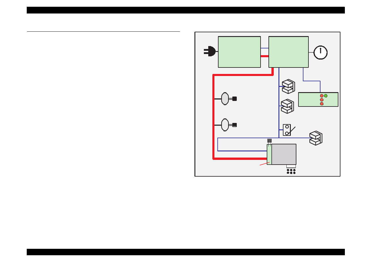
EPSON Stylus Color 440/640/740
Revision A
Chapter 2
Operating Principles
56
2.2 Electrical Circuit Operating Principles
Stylus Color 440/640/740 contains the following three electric circuit
boards.
Electronic Boards for Stylus Color 440 are;
Main:
C206 Main-B, C255 Main Board
Power Supply:
C206 PSB,PSE Board
Panel:
C206 PNL Board
Electronic Boards for Stylus Color 640 are;
Main:
C256 Main, Main Board
Power Supply:
C206 PSB,PSE Board
Panel:
C206 PNL Board
Electronic Boards for Stylus Color 740 are;
Main:
C257 Main, Main Board
Power Supply:
C257 PSB,PSE Board
Panel:
C209 PNL Board
Refer to Figure 2-15 for the major connection of the 3 boards and their
roles.
Figure 2-15. Electric Circuit of Stylus Color 440, 640, 740
PF MOTOR
(Pump Motor)
CR Motor
C206 PSB/PSE Board
C257 PSB/PSE Board
+5 V DC
AC Input
INK END counter
and P-off time
counter
PE Sensor
BCO/CCO Sensor
ASF Lever
Position Sensor
Print Head
+42 V DC
Head Drive Board
CRHP Sensor
Thermistor
12
6
3
9
1
2
4
5
7
8
10
11
C206 Main-B
C255 Main
C256 Main
C257 Main
+5 V DC
+42 V DC
C206 PNL
C209 PNL
LED
+5 V DC
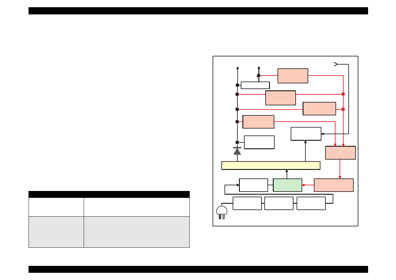
EPSON Stylus Color 440/640/740
Revision A
Chapter 2
Operating Principles
57
2.2.1 C206 PSB/PSE and C257 PSB/PSE Power
Supply Board (for Stylus Color 440, 640, 740)
There are 2 types of power supply boards for Stylus Color 440/640/740.
The main components of the boards are the same, but the +5V
regulator ICs which create steady +5V are different. These boards are
power supply board with a RCC switching regulator, which generates
+42VDC for drive part and +5VDC for logic part to drive the printer. One
of the major characteristic of this board is that the same secondary
switch is used as Stylus Color series printer. By using this switch, the
following difference can be seen as superficial phenomena compared
with products applied with primary switch method, such as Stylus Color
IIs, II and Stylus 800/1000 series printer. The table below shows
application of voltages generated by C206 PSB/PSE board.
1. Even if the switch is turned off during the middle of printer operation,
since the driving power is turned off after the carriage goes back to
the carriage lock position, the possibility of clogging ink nozzle will
be decreased.
2. If the switch is turned off when the papers in the printer are still
being carried except for the papers in the hopper, the same
operation mentioned above is performed and the driving power is
turned off after the paper is completely ejected.
Table 2-8. Application of DC Voltage
Figure 2-16 shows block diagram of C206 PSB/PSE board. The
process from the input of AC voltage to the output of 42 V DC and 5 V is
explained in the following pages.
Figure 2-16. C206/C257PSB, PSE Board Block Diagram
Voltage
Application
+42VDC
CR Motor
PF/Pump Motor
Head driving power supply
+5VDC
Power supply for logic control
System control signal
Sensor circuit power supply voltage
LED panel drive power supply
Nozzle selector control signal power supply voltage
F1
C11
L1,R1-2
C1-C4
DB1
TRANS(T1)
Over Current
Protection
Filter Circiut
Full Wave
Rectifier circuit
Smoothing
Circuit
Main Switching
Circuit
Q1
Abnormal
Feed back circuit
Q2,Q3,Q31
Photo
Coupler
PC1
D51
AC Input
Smoothing
Circuit
C51
+42VDC Line
Constant Control
ZD81-86,ZD51
Power Drop
Delay Circuit
C84,Q84
+42VDC Line
Over Voltage
Limitation
ZD52,87
+5V Regulator
IC51
+42 VDC
+5 VDC
+5VDC Line
Over Voltage
Limitation
PSC Signal
from Main board
ZD53
+42VDC Lin Drop
Limitation Circuit
ZD90

EPSON Stylus Color 440/640/740
Revision A
Chapter 2
Operating Principles
58
1) Regardless of the state of power switch (On or OFF), the voltage is
always applied in the primary side of the power supply board from
the moment or at the state that AC-plug is plugged in. At this time,
F1 plays a role of preventing AC100V from coming into the F1. L1
and R1-R2 also prevent high harmonic wave noise generated in the
RC circuit filter which consist of C1
∼
C4 and R1
∼
R2 from going out,
and eliminate the noise from outside here.
2) The AC is full-wave rectified by diode bridge DB1, and converted to
x AC in voltage by smoothing electrolytic capacitor C11.
3) The pressured up direct current makes Q1 On through the starting
resistor R31 and starts the primary side of the circuit.
4) When the primary side is On state, the energy(current) led by the
electromagnetic induction through the trans (T1) does not flow to the
secondary side since the diode(D51) on the secondary side is
installed in the opposite direction.
5) When the energy which is charged in the trans is reaching the
saturated state, the voltage which makes the Q1 On becomes weak
gradually. At the point that this voltage drops at the certain voltage,
C13 absorbs the current in the opposite direction and Q1 is quickly
shut off by the resulting sharp drop.
6) When the primary side is turned off, the energy charged in the T1 is
opened according to the diode(D51) direction which is installed on
the secondary side. Basically, 42 V DC is output by these circuit
operations and the number of T1 spiral coil.
7) +5VDC is generated by pressured down this +42VDC as power
supply. IC51 pressures down the +42VDC and generates precise
+5VDC by chopping off the output, forming the standard santooth
wave form by the outer RC integration circuit.
The C206 PSB/PSE board has various control circuits to stop output if
malfunction on the power supply board, on the main board or on the
duty of printer mechanism happen. Following explains each control and
protection circuits.
+42V Line Constant Voltage Control Circuit:
The output level of the +42V line is monitored by a detection circuit
consisting of seven Zener diodes. This circuit prevents voltage from
dropping for constant output voltage.
+5V Line Over voltage Protection Circuit:
This protection circuit is in the same line as +42V over voltage
protection circuit is located. The output voltage level of the +5V line
is monitored by a Zener diode. This circuit shuts down the circuit
operation forcefully when the voltage level exceeds +9V.
+42VDC Line Drop Limitation Circuit:
This protection circuit is in the same line as +42V over voltage
protection circuit is located. The output voltage level of the +42V line
is monitored by a Zener diode. This circuit shuts down the circuit
operation forcefully when the voltage level drops +36V.
+42VDC Line Over voltage Circuit:
This circuit is in the same line as +5V line over voltage protection
circuit is located. The output level is monitored by two Zener diodes.
If the voltage level exceeds +48VDC, this circuit stops circuit
operation forcefully.
+5V Line Constant Voltage/Constant Current Control Circuit:
The output current is monitored by a +5VDC generation switching
control IC(IC51), which also monitors the output voltage. This
information is input to the internal comparator and stabilizes +5V
line. Operation of the secondary side switch is explained in the
following page.
2

EPSON Stylus Color 440/640/740
Revision A
Chapter 2
Operating Principles
59
When the power is turned on, Q1 repeats ON/OFF automatically
along with the increase and decrease of energy on the trans coil
at the primary side. While the power is being on, PSC signal is
input to the power supply board from the C206 Main-B/C255/
C256/C257 Main board.
This signal turns Q84 on and it becomes possible to discharge
energy between 8-9 of T1. At this time, even if the power is
turned off, the electrolytic capacitor keeps Q84 on for a while. By
this electrolytic capacitor, output is hold at least 30 seconds
even after the power is turned off. This time helps the printer to
complete the P-Off operation.
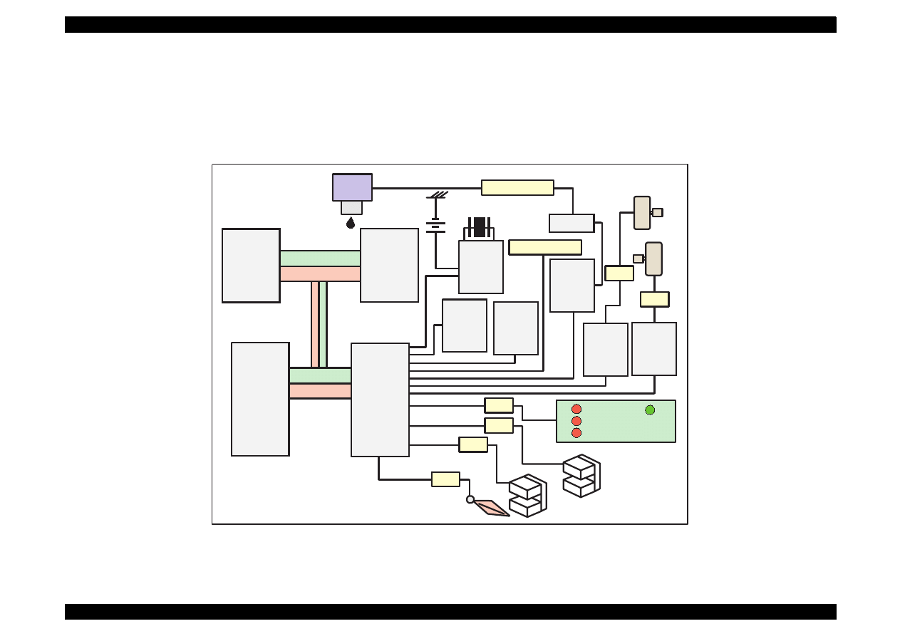
EPSON Stylus Color 440/640/740
Revision A
Chapter 2
Operating Principles
60
2.2.2 C206 Main-B, C255 Main (for Stylus Color 440)
Various DC voltage generated on the C206 PSB/PSE board is added
various signals in order to drive the printer function on the C206 main-B,
C255 main, board the drive of CR/PF (Pump) motor and printing head is
performed. Following figure shows the circuit diagram for Stylus Color
440.
Figure 2-17.
C206 Main-B, C255 Main Board Block for Stylus Color 440
TPM95C061
(IC1)
P-ROM
(IC3)
Address
Data
Address
Data
Reset IC
(IC9)
CR1
Timer
Counter
(IC5)
Batt1
EEPROM
(IC11)
CN1 Parallel
Common
Driver
(IC6)
Q7&Q9
Head
CN8 HD FFC
Motor
Driver
(IC14)
Motor
Driver
(IC15)
PF Motor
CR Motor
CN6
CN7
C206 PNL
CN3
CN11
ASF Sensor
CN5
HP Sensor
CN4
PE Sensor
E05B44
(IC2)
D-RAM
(IC4)

EPSON Stylus Color 440/640/740
Revision A
Chapter 2
Operating Principles
61
[CPU]
The 16-bit CPU which is mounted on Stylus Color 440 is running at
25Mhz. Gate array manages most of controls and monitors. Likewise
the Stylus Color, the D-RAM is applied for RAM which is used as work
area for receiving data and developing the data and CPU manages its
control such as CE, RAS/CAS controls.
[Gate Array]
E05B44 controls the following functions.
Motor control
Each motor performs data transmission that motives Micro-Step.
Head voltage control
In the ink jet printers, drive voltage wave form (trapezoidal wave
form) in order to drive PZT is formed in the various shapes
according to the types of the printers. Therefore, it is necessary to
form appropriate drive form for each head. Head voltage control
forms necessary wave form for each control signals and outputs
them.
EEPROM control
The correction value to eliminate the error of each printers at
production process is installed in the fixed address of IC. When the
power is turned off, the contents set by users is written instantly, and
is red to the RAM when the power is turned on.
Sensor Data
The sensor detects information at the various conditions, which is
necessary for the printer operation. The gate array recognizes
signals and changes over to the next control.
Timer Data
The timer IC that uses lithium battery as power source monitors how
long the power is off. When the power is turned on, it is changed to
appropriate cleaning level according to the time that the power is off.
Parallel I/F control
With the use of IEEE1284 Nibble mode, it became possible not only
to receive the data from the host but also to return various
information which the printer possesses to the host.
[Common Driver IC]
The trapezoidal wave form circuit for the head drive is HIC, an
improvement from the previous discrete structure. Because of this, it is
not necessary to adjust the adjustable VR on the board during
production process. Various electric charge/discharge control signals
are all processed in the HIC.
[CR/PF Motor Drive Circuit]
Constant current drive is performed by the HIC. Out of this, only CR
Motor is controlled for Micro-Step control and HIC becomes possible to
flow the appropriate current value at each steps. (PF Motor has only 1-
2, 2-2 phase drive method). Also, bipolar drive is performed on the 4
cables individually.
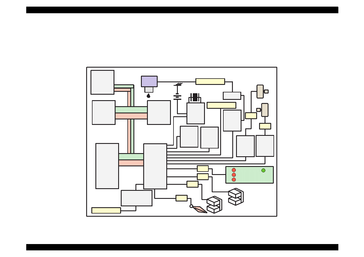
EPSON Stylus Color 440/640/740
Revision A
Chapter 2
Operating Principles
62
2.2.3 C256 Main (for Stylus Color 640)
Various DC voltage generated on the C206 PSB/PSE board is added
various signals in order to drive the printer function on the C256 main
board, and the drive of CR/PF (Pump) motor and printing head is
performed. Following figure shows the circuit diagram for Stylus Color
640.
Figure 2-18. C256 Main Board Block for Stylus Color 640
TPM95C061
(IC1)
Address
Data
Address
Data
Reset IC
(IC9)
CR1
Timer
Counter
(IC10)
Batt1
EEPROM
(IC11)
CN1 Parallel
Common
Driver
(IC7)
Q7&Q9
Head
CN8 HD FFC
Motor
Driver
(IC14)
Motor
Driver
(IC15)
PF Motor
CR Motor
CN6
CN7
C206 PNL
CN3
CN11
ASF Sensor
CN5
HP Sensor
CN4
PE Sensor
E05B43
(IC2)
Transceiver
(IC16)
CN2 Serial
P-ROM
(IC3)
D-RAM
(IC5)
M-ROM
(IC6)

EPSON Stylus Color 440/640/740
Revision A
Chapter 2
Operating Principles
63
[CPU]
The 16-bit CPU which is mounted on Stylus Color 640 is running at
25Mhz. Gate array manages most of controls and monitors. Likewise
the Stylus Color, the D-RAM is applied for RAM which is used as work
area for receiving data and developing the data and CPU manages its
control such as CE, RAS/CAS controls.
[Gate Array]
E05B43 controls following functions.
Motor control
Each motor performs data transmission that motives Micro-Step.
Head voltage control
In the ink jet printers, drive voltage wave form (trapezoidal wave
form) in order to drive PZT is formed in the various shapes
according to the types of the printers. Therefore, it is necessary to
form appropriate drive form for each head. Head voltage control
forms necessary wave form for each control signals and outputs
them.
EEPROM control
The correction value to eliminate the error of each printers at
production process is installed in the fixed address of IC. When the
power is turned off, the contents set by users is written instantly, and
is red to the RAM when the power is turned on.
Sensor Data
The sensor detects information at the various conditions, which is
necessary for the printer operation. The gate array recognizes
signals and changes over to the next control.
Timer Data
The timer IC that uses lithium battery as power source monitors how
long the power is off. When the power is turned on, it is changed to
appropriate cleaning level according to the time that the power is off.
Serial I/F Control
The gate array receives serial data through the transceiver IC.
Parallel I/F control
With the use of IEEE1284 Nibble mode, it became possible not only
to receive the data from the host but also to return various
information which the printer possesses to the host.
[Common Driver IC]
The trapezoidal wave form circuit for head drive is became to HIC from
the previous discrete structure. Because of this, it is not necessary to
adjust the adjustable VR on the board during production process.
Various electric charge/discharge control signals are all processed in
the HIC.
[CR/PF Motor Drive Circuit]
Constant current drive is performed by the HIC. Out of this, only CR
Motor is controlled for Micro-Step control and HIC becomes possible to
flow the appropriate current value at each steps. (PF Motor has only 1-
2, 2-2 phase drive method). Also, bipolar drive is performed on the 4
cables individually.
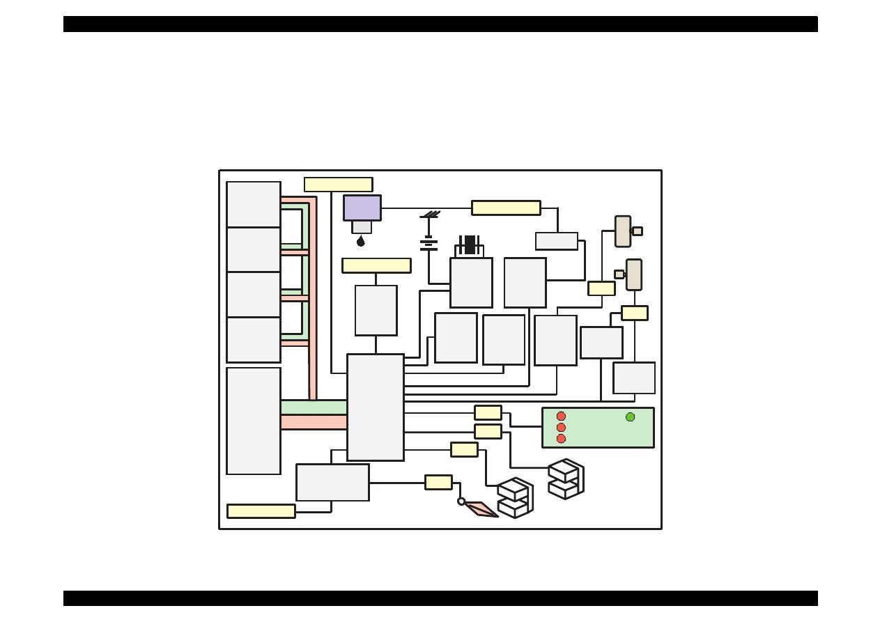
EPSON Stylus Color 440/640/740
Revision A
Chapter 2
Operating Principles
64
2.2.4 C257 Main, (for Stylus Color 740)
Various DC voltage generated on the C257 PSB/PSE board is added
various signals in order to drive the printer function on the C257 main
board the drive of CR/PF (Pump) motor and printing head is performed.
Following figure shows the circuit diagram for Stylus Color 740.
Figure 2-19. C257 Main Board Block for Stylus Color 740
Address
Data
Reset IC
(IC9)
CR1
Timer
Counter
(IC8)
Batt1
EEPROM
(IC7)
CN1 Parallel
Q2&Q3
Head
CN9 HD FFC
PF Motor
CR Motor
CN7
C209 PNL
CN11
CN6
ASF Sensor
CN4
HP Sensor
CN5
PE Sensor
Transceiver
(IC10)
CN2 Serial
Motor
Driver
(IC13)
Common
Driver
(IC14)
CN8
Motor
Driver
(IC12)
Buffer
(IC9)
CN3 USB
P-ROM
(IC3)
D-RAM
(IC4)
M-ROM
(IC6)
D-RAM
(IC5)
Motor
Driver
(IC11)
C90A05
(IC1)
E05B588
(IC2)

EPSON Stylus Color 440/640/740
Revision A
Chapter 2
Operating Principles
65
[CPU]
The 16-bit CPU which is mounted on Stylus Color 740 is running at
24Mhz. Gate array manages most of controls and monitors. Likewise
the Stylus Color, the D-RAM is applied for RAM which is used as work
area for receiving data and developing the data and CPU manages its
control such as CE, RAS/CAS controls.
[Gate Array]
E05B588 controls following functions.
Motor control
Each motor performs data transmission that motives Micro-Step.
Head voltage control
In the ink jet printers, drive voltage wave form (trapezoidal wave
form) in order to drive PZT is formed in the various shapes
according to the types of the printers. Therefore, it is necessary to
form appropriate drive form for each head. Head voltage control
forms necessary wave form for each control signals and outputs
them.
EEPROM control
The correction value to eliminate the error of each printers at
production process is installed in the fixed address of IC. When the
power is turned off, the contents set by users is written instantly, and
is red to the RAM when the power is turned on.
Sensor Data
The sensor detects information at the various conditions, which is
necessary for the printer operation. The gate array recognizes
signals and changes over to the next control.
Timer Data
The timer IC that uses lithium battery as power source monitors how
long the power is off. When the power is turned on, it is changed to
appropriate cleaning level according to the time that the power is off.
Serial I/F Control
The gate array receives serial data through the transceiver IC.
Parallel I/F control
With the use of IEEE1284 Nibble mode, it became possible not only
to receive the data from the host but also to return various
information which the printer possesses to the host.
USB I/F Control
The transceiver circuit which control the USB interface has been
incorporated into this gate array.
[Common Driver IC]
The trapezoidal wave form circuit for head drive is became to HIC from
the previous discrete structure. Because of this, it is not necessary to
adjust the adjustable VR on the board during production process.
Various electric charge/discharge control signals are all processed in
the HIC.
[CR/PF Motor Drive Circuit]
Constant current drive is performed by the HIC. Out of this, only CR
Motor is controlled for Micro-Step control and HIC becomes possible to
flow the appropriate current value at each steps. (PF Motor has only 1-
2, 2-2 phase drive method). Also, bipolar drive is performed on the 4
cables individually.
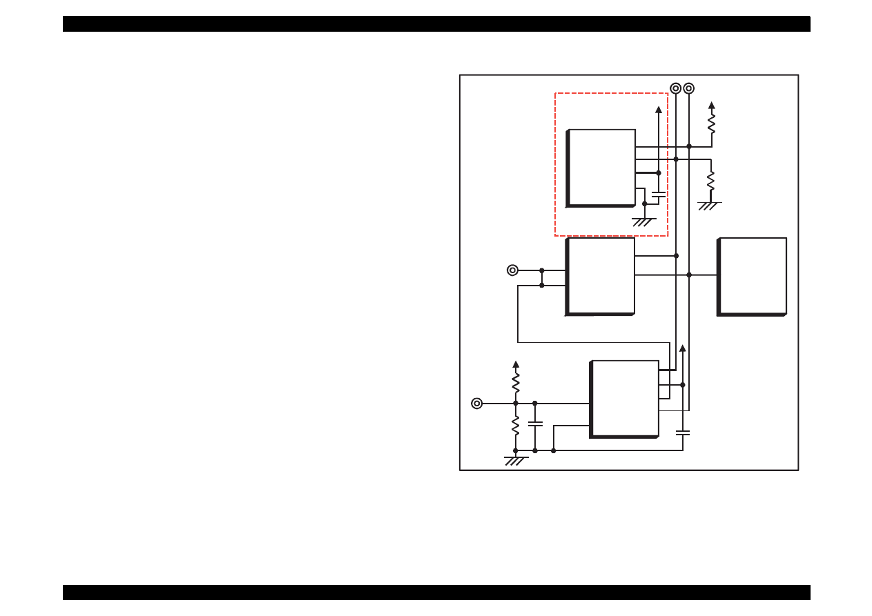
EPSON Stylus Color 440/640/740
Revision A
Chapter 2
Operating Principles
66
2.2.4.1 Reset Circuits
[C206 Main-B, C255 Main for Stylus Color 440]
The reset circuit prevents the CPU from running away, which is caused
by the unstable voltage in the logic line during the power ON/OFF
operation. And reset IC(IC9) monitors level of power voltage at the over
loading or malfunction on the circuit and manages the printer to operate
normally, keeping the damage to the printer minimum during the
abnormal situations. On the C206 main-B and C255 main board.
Figure 2-20. Reset Circuit for Stylus Color 440
PST592D
(IC8)
Vcc
Vout
NRES
GND
+5V
C47
R138
+5V
R1
/RESET
TMP95C061
(IC1)
P85
E05B44
(IC2)
/RESET
174
30
16
1
2
3
4
M62030
(IC9)
VCC
2
4
R6
+42V
R10
+5V
NC8
NC5
OUT
/NMI
10
P84
15
5
6
7
8
GND
IN
Not mounted
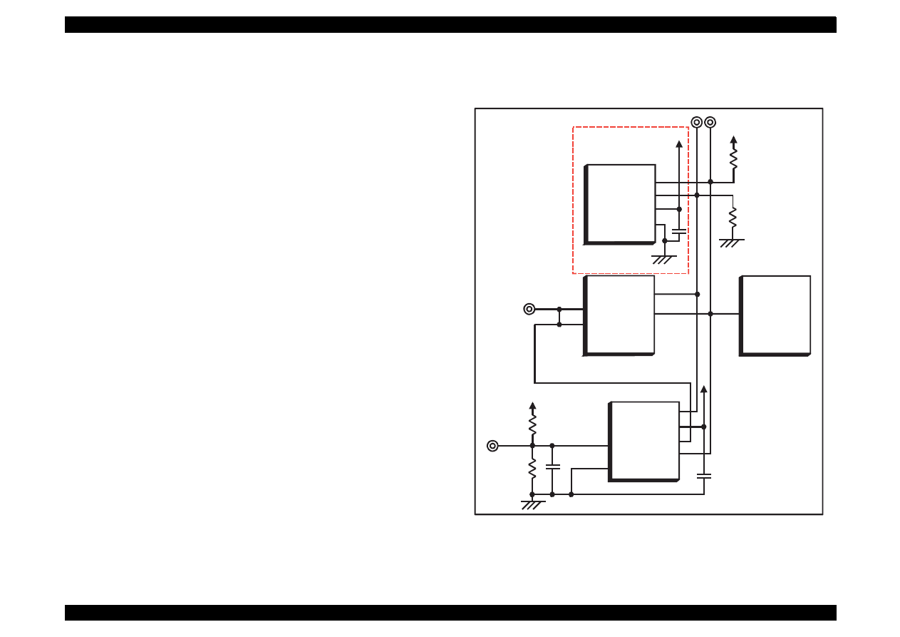
EPSON Stylus Color 440/640/740
Revision A
Chapter 2
Operating Principles
67
[C256 Main for Stylus Color 640]
The reset circuit prevents the CPU from running away, which is caused
by the unstable voltage in the logic line during the power ON/OFF
operation. And reset IC(IC9) monitors level of power voltage at the over
loading or malfunction on the circuit and manages the printer to operate
normally, keeping the damage to the printer minimum during the
abnormal situations. On the C256 main board.
Figure 2-21. Reset Circuit for Stylus Color 640
PST592D
(IC8)
Vcc
Vout
NRES
GND
+5V
C47
R138
+5V
R1
/RESET
TMP95C061
(IC1)
P85
E05B43
(IC2)
/RESET
174
30
16
1
2
3
4
M62030
(IC9)
VCC
2
4
R6
+42V
R10
+5V
NC8
NC5
OUT
/NMI
10
P84
15
5
6
7
8
GND
IN
Not mounted
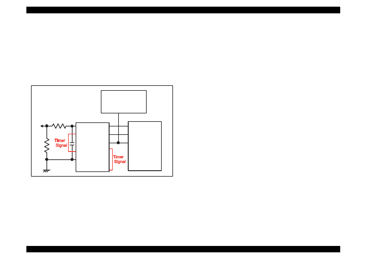
EPSON Stylus Color 440/640/740
Revision A
Chapter 2
Operating Principles
68
[C257 Main for Stylus Color 640]
The reset circuit prevents the CPU from running away, which is caused
by the unstable voltage in the logic line during the power ON/OFF
operation. And reset IC(IC8) monitors level of power voltage at the over
loading or malfunction on the circuit and manages the printer to operate
normally, keeping the damage to the printer minimum during the
abnormal situations. On the C257 main board. The IC 8 has 2 functions
both the timer counter and creating a reset signal.
Figure 2-22. Reset Circuit for Stylus Color 740
2.2.4.2 Sensor Circuits
The following sensor circuits are mounted in the Stylus Color 440/640/
740 and selects appropriate operations based on the returned status.
ASF Sensor (Photo):
An ASF sensor detects the position of return lever when the power
is turned on, and causes the paper to be picked up by the pick up
roller from the normal initial condition. (Refer to section 2.1.1.3 for
detail.)
PE Sensor (Photo):
A PE sensor determines if there is paper in the printer. Based on the
signal form this sensor, a particular paper edge treatment such as
Micro-weave printing is performed.
HP Sensor (Photo):
A HP sensor detects the carriage home position. It is used for
managing printing position and cleaning, etc.
Thermistor Sensor
A thermistor sensor keeps stable printing quality, changing PZT
drive voltage(VH) slightly according to changes of environmental
temperature.
Cartridge Sensors:
Cartridge sensors are built into the Bk, CMY cartridge on the
carriage unit respectively to determine if the cartridge is installed or
not when it is exchanged or the power is turned on. In case of Stylus
Color 440/640/740, the counter is reset at every time the cartridge is
removed.
/NMI
MRES
/RESET
IC 1
C90A05
/RES
B1
10
3
2
29
24
25
+42
VIN
VDD
VBK
GND
/VDT
FRST
/RST
CE
SCLK
DATA
IC 8
RTC-9810
IC 2
E05B588
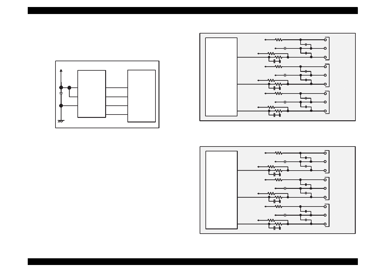
EPSON Stylus Color 440/640/740
Revision A
Chapter 2
Operating Principles
69
The following three figures show the sensor circuits. Out of the data
such as EPW with IEEE 1284 Nibble mode to be returned to the host,
the data to indicate ink consumption is calculated and managed by the
counter of the firmware. Therefore, it is omitted here.
Figure 2-23. Figure 5-23. Sensor Circuit for Stylus Color 440
Figure 2-24. Figure 5-24. Sensor Circuit for Stylus Color 640
Figure 2-25. Sensor Circuit for Stylus Color 740
+5V
8
6
5
AT93C46
(IC11)
Vcc
GND
ORG
E05B44
(IC2)
127
128
126
125
1
2
3
4
CS
SK
DI
DO
ECS
ECK
ECO
ECI
IC 2
E05B43
+5V
+5V
CN11
CN5
CN4
ASF
HP
PE
PE
GND
PEV
HP
GND
HPV
ASF
GND
ASFV
+5V
+5V
+5V
+5V
+5V
+5V
+5V
206
SW4
204
SW5
202
SW6
IC 2
E05B588
+5V
+5V
CN4
CN5
CN6
ASF
HP
PE
PE
GND
PEV
HP
GND
HPV
ASF
GND
ASFV
+5V
+5V
+5V
+5V
+5V
+5V
+5V
97
SWA0
98
SWA1
99
SWA2
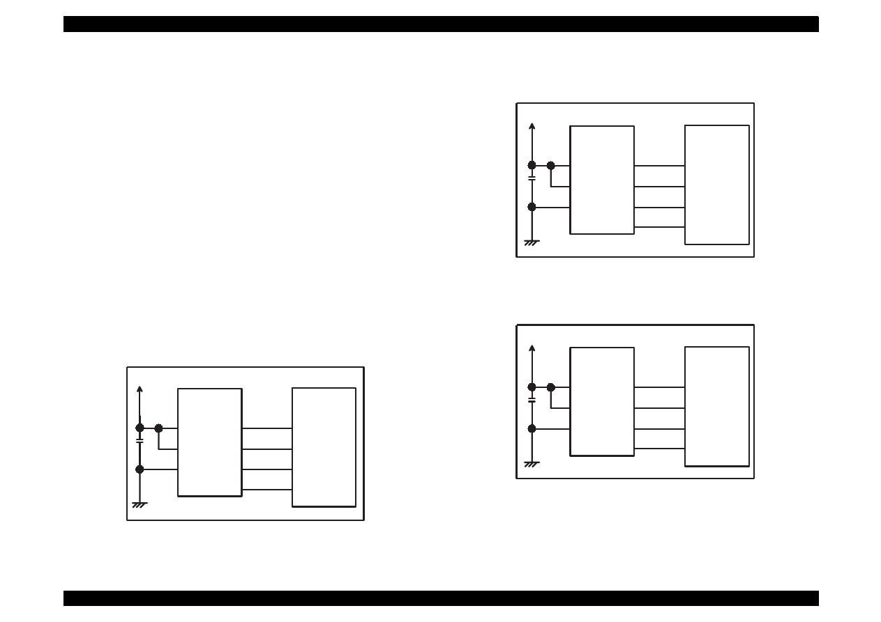
EPSON Stylus Color 440/640/740
Revision A
Chapter 2
Operating Principles
70
2.2.4.3 EEPROM Control Circuits
The EEPROM of Stylus Color 440/640/740 has following contents. Gate
array controls operations of reading data when the power is on and
writing data when the power is off.
Ink consumption (Bk, CMY)
CL counter (Various cleaning operations that are previously
done are memorized)
Destination information
Information of various adjustment values (Bi-D, VH voltage, etc.)
CPSI pass word
Other various setting values by the user
EEPROM is connected to the Gate array by 4 lines and performs
following functions. The figure below shows EEPROM control circuit.
CS:
Chip selection signal
CK:
Data synchronism clock pulse
DI:
Data writing line (serial data) at power off.
DO:
Data reading line (serial data) at power on.
Figure 2-26. EEPROM Control Circuit for Stylus Color 440
Figure 2-27. EEPROM Control Circuit Stylus Color 640
Figure 2-28. EEPROM Control Circuit for Stylus Color 740
+5V
8
6
5
AT93C46
(IC11)
Vcc
GND
ORG
E05B44
(IC2)
127
128
126
125
1
2
3
4
CS
SK
DI
DO
ECS
ECK
ECO
ECI
+5V
8
6
5
AT93C46
(IC11)
Vcc
GND
ORG
E05B43
(IC2)
130
129
128
127
1
2
3
4
CS
SK
DI
DO
ECS
ECK
ECO
ECI
+5V
8
6
5
AT93C46
(IC7)
Vcc
GND
ORG
E05B588
(IC2)
206
205
204
203
1
2
3
4
CS
SK
DI
DO
EECS
EECK
EECO
EECI
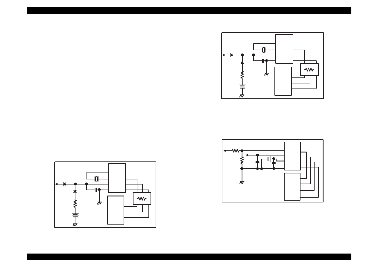
EPSON Stylus Color 440/640/740
Revision A
Chapter 2
Operating Principles
71
2.2.4.4 Timer Circuit
A lithium battery is mounted on the main board and calculates how long
the printer is not used. The timer IC starts counting with oscillation
motivated by the crystal oscillator using this battery as a power source.
The following figures show connection of the Timer circuit. The
followings explain about operation of this circuit.
When the printer is on, power is supplied to the Timer IC by
applying +5V quickly through the D1.
This power is also used for the power to oscillator. The
oscillation wave form is input to XI terminal.
Since the oscillation wave form of CR1 is analog wave form, it is
processed into the pulse form in the Timer IC.
When the printer is turned on, the Timer IC outputs power off
time as serial data to the gate array.
Once the printer is turned off, 3VDC of BAT1(lithium battery) is
supplied as power source for the Timer IC through D7.
Since +5V at the power on is higher than +3V of the lithium
battery, the power is not being consumed from the lithium
battery.
Figure 2-29. Timer Control Circuit for Stylus Color 440
Figure 2-30. Timer Counter Circuit for Stylus Color 640
Figure 2-31. Timer Counter Circuit for Stylus Color 740
+5
Batt1
D7
D1
C4
0.1u
S-3510ANF
(IC5)
X I
X O
2
3
VCC
GND
8
4
5
6
7
123
121
124
CR1
E05B44
(IC2)
TCE
TCLK
TDATA
RM7
CS
/SCK
/SIO
+5
Batt1
D1
D4
C4
0.1u
S-3510ANF
(IC10)
XI
XO
2
3
VCC
GND
8
4
5
6
7
125
123
126
CR3
E05B43
(IC2)
TCE
TCLK
TDATA
RM7
CS
/SCK
/SIO
+42
RTC-9810
(IC8)
Vin
9
7
8
5
6
4
CE
SCLK
Data
Vdd
Vbk
GND
20
21
23
E05B588
(IC2)
TMCS
TMCK
TMDATA
/RST
2
25
+5
14
Batt1

EPSON Stylus Color 440/640/740
Revision A
Chapter 2
Operating Principles
72
2.2.4.5 DRAM Control
In the Dynamic RAM control, output and formation of CAS and RAS
control signals become necessary in addition to the output of CS signal.
The CPU not only controls that but also perform the output of CS signal
of P-ROM. Refresh timing is performed in the CAS Before RAS.
2.2.4.6 Print Head Control Circuit
The print head control circuit of Stylus Color 440/640/740 has following
characteristics.
Common wave form circuit became one HIC.
Slight vibration mode is added.(when the CR motor is
accelerating)
High speed drive 14.4Khz (trapezoidal wave form
Big Nozzle configuration (resolution in the vertical
direction)90dpi
(However, black nozzle is 2 lines structure)
Also, Stylus Color 440/640/740 does not have Micro-dot control as dot
shooting control, but there are two types; Normal-dot and Normal dot-
2dot.Normal-dot-2dot was called Dual Firing in the Stylus Color IIs/820.
These setting/change are controlled automatically by setting of the
printer driver that is determined by the user. The followings are required
conditions to perform the normal-dot 2-dot.
At the OHP, Normal sheet setting (360X360 dpi)
At the ordinary paper and resolution 360X360 dpi setting
The control circuit is considered as 2 divided parts; 1) trapezoidal wave
form generation circuit (common drive circuit) to drive PZT in the head,
and 2) Nozzle-selector drive circuit to determine which nozzle should be
used. The Nozzle-Selector is attached to the head unit just like the
previous models. The common drive circuit is hybridized as one HIC
and mounted on the main control board.
See the following pages for the head drive circuit block diagrams for
each printer.
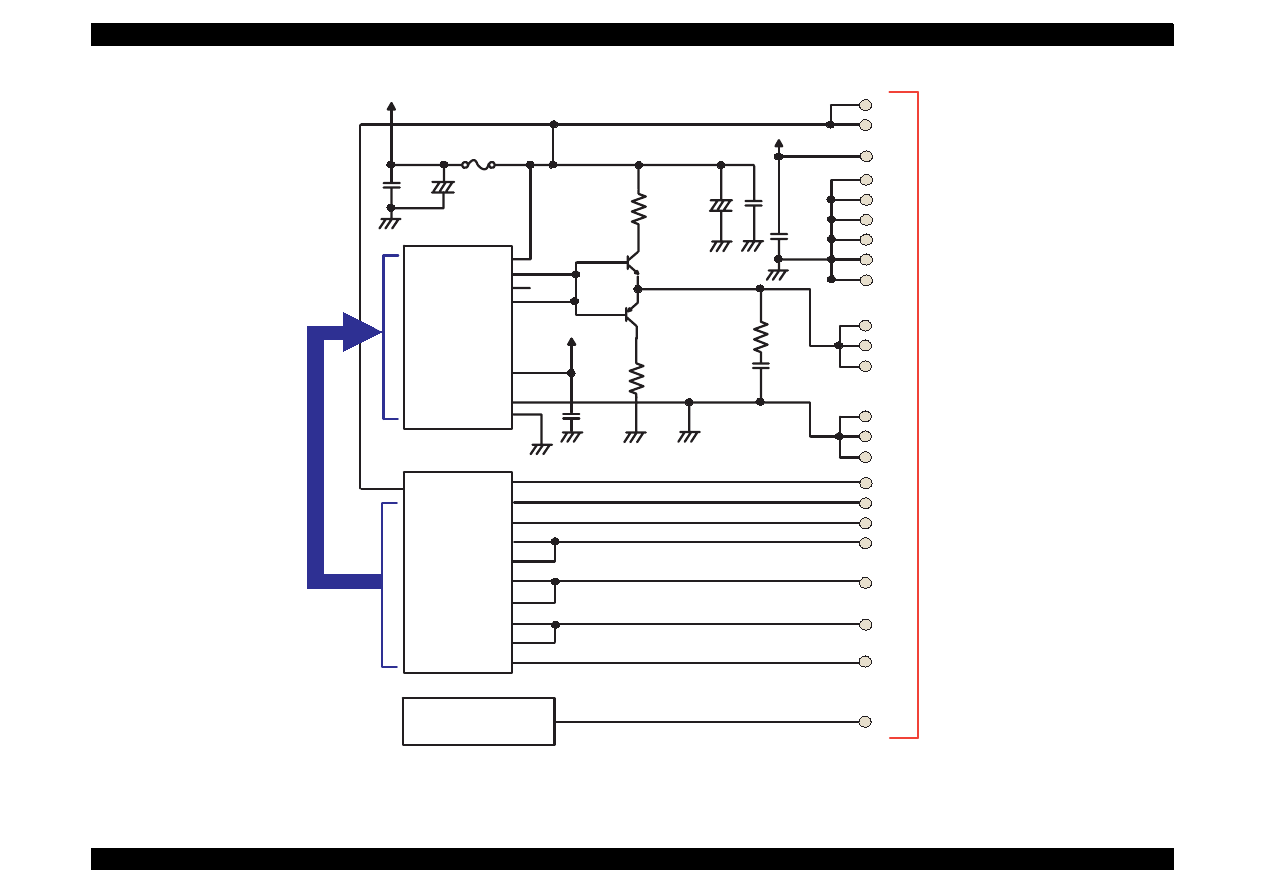
EPSON Stylus Color 440/640/740
Revision A
Chapter 2
Operating Principles
73
Figure 2-32. Head Drive Circuit for Stylus Color 440
H8D2813(IC6)
XOVM
CTB
COM
DTB
GND
GND
25
1
20
+5
F1
+42
22
23
VHV
VHV
+5
GND
GND
GND
GND
GND
GND
VDD
15
14
12
10
8
6
4
COM
COM
COM
19
21
20
GND2
GND2
GND2
16
18
17
E05B44(IC2)
VHCTL
2
4
6
199
CCO
LAT
SI1
SI2
CLK
NCHG
BCO
THM
1
2
5
9
7
11
3
13
200
198
SW7
SW8
90
LP
99
100
BIEN
BHSO
YCMHSO
97
96
YCMIEN
ICLK
BCHCLK
/NCHG
93
92
89
TMP95C061(IC1)
AN0
20
CN8
CHG
KC1
ND1
ND2
MD1
MD2
Data
CLK
/STB
/CLR
VRF
VK
CHG
KC1
ND1
ND2
MD1
MD2
Data
CLK
/STB
/CLR
VRF
VK
VHCTL
Vcc
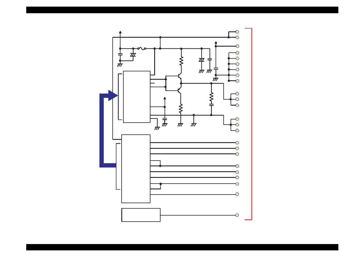
EPSON Stylus Color 440/640/740
Revision A
Chapter 2
Operating Principles
74
Figure 2-33. Head Driver Circuit for Stylus Color 640
H8D2813(IC7)
XOVM
CTB
COM
DTB
GND
GND
25
1
20
+5
F1
+42
22
23
VHV
VHV
+5
GND
GND
GND
GND
GND
GND
VDD
15
14
12
10
8
6
4
COM
COM
COM
19
21
20
GND2
GND2
GND2
16
18
17
E05B43(IC2)
VHCTL
2
4
6
199
CCO
LAT
SI1
SI3
CLK
NCHG
BCO
THM
1
2
5
11
7
13
3
15
201
199
SW7
SW8
92
LP
HSO3
101
ICLK
HCLK
/NCHG
94
95
91
TMP95C061(IC1)
P84
15
CN8
CHG
KC1
ND1
ND2
MD1
MD2
Data
CLK
/STB
/CLR
VRF
VK
CHG
KC1
ND1
ND2
MD1
MD2
Data
CLK
/STB
/CLR
VRF
VK
VHCTL
Vcc
SI2
9
HSO2
99
HSO1
97
HSOIEN
96
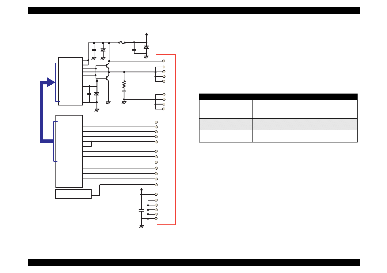
EPSON Stylus Color 440/640/740
Revision A
Chapter 2
Operating Principles
75
Figure 2-34. Head Drive Circuit for Stylus Color 740
[Common drive circuit]
The shape of trapezoidal wave form will be different according to the
printing operation, slight vibrations at the non-printing nozzle and
waiting condition. However, the IC6(for Stylus Color 440), IC7(for Stylus
Color 640), IC14(for Stylus Color 740) generates all wave forms as
drive wave forms by resistance(electric) welding control of common
voltage drive control signal that is output from the IC2(gate array) in the
figure above.
Table 2-9.
Specifications of H8D2813/CXA20995 for Stylus Color 440, 640, 740
This common voltage trapezoidal wave form can be observed anytime
after the +5V rises even if there is printing data or not. (Q7:3-pin,Q9:3-
pin for Stylus Color 440 and Q2: 3-pin, Q3: 3-pin for Stylus Color 640,
740)
[Nozzle Selector Drive Circuit]
In order to motivate the print head to carry out printing, it is necessary to
transmit the printing data to the appropriate nozzles, which becomes
direct signals to drive PZT. This data transmission is performed by the
serial method, however the data output for each black and CMY head is
transmitted by the parallel method.
CXA20996(IC14)
VCC45
Vcc45_2
NPNB
FB
PNPB
VOUTGND
F1
E05B588(IC2)
VHCTL
22
20
CCO
LAT
CLK
BCO
THM
1
2
5
14
11
3
190
SWC0
184
HLAT
IECLK
AN0
105
A0
A1
A2
A3
CLK1
CLK2
/FLOOR
/RST
DATA
DCLK
/E
HWA0
HWA1
HWA2
HWA3
HWCLK1
HWCLK2
/HWFLR
/HWRST
HWSDATA
HWSCLK
/HWSLAT
SI1
12
174
HNCHG
+42
23
18
16
22
21
20
19
26
25
24
23
GND2
GND2
GND2
GND2
COM
COM
COM
COM
VHV
27
VCC5
+5
24
14
SWC1
189
173
NCHG
16
HCLK
175
176
HSI1
SI2
HSI2
177
10
SI3
HSI3
178
8
SI4
9
179
HSI4
SI5
HSI5
180
7
SI6
HSI6
181
TMP95C061(IC1)
GND
GND
GND
GND
GND
+5
GND
18
17
15
13
6
4
CN9
Items
COntents
Drive Power Voltage
42
±
5%
Starts supplying after 5V rises and be stabilized./
Stops supplying before +5V drops.
Final Drive Element
2SC3746(for charging),
2SA1469(for discharging)
Operation at the Reset
Off on the both charging and discharging sides.
Supplies drive power source.
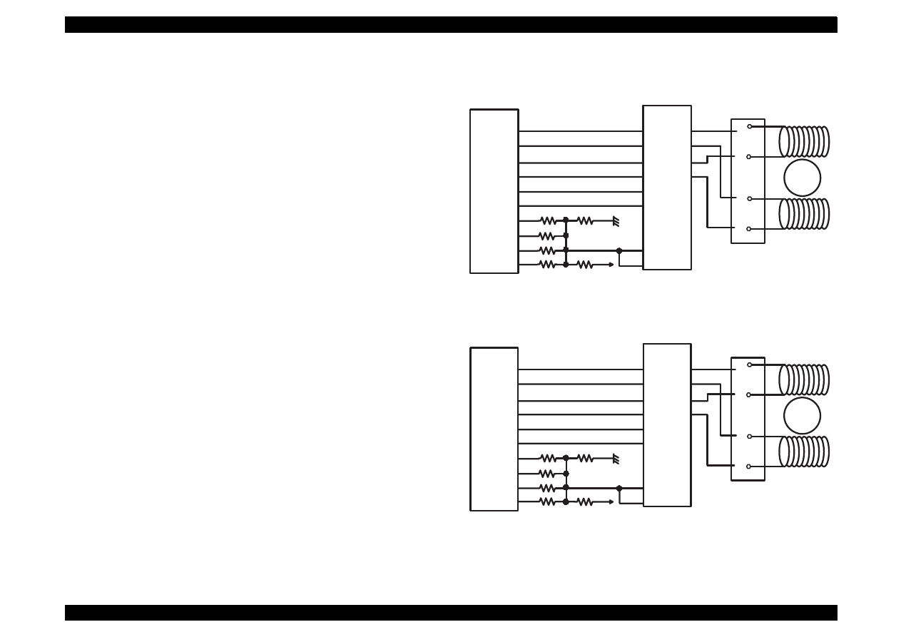
EPSON Stylus Color 440/640/740
Revision A
Chapter 2
Operating Principles
76
2.2.4.7 PF (Pump) Motor Drive Circuit
IC15(LB1845) on C206 Main-B, C255 Main board, IC15(UDN2917) on
C256 Main board, and IC12/13(A3956) on C257 Main board are used
for driving PF (Pump) motor. In the IC, Bi-pola drive PWM current
control type is performed, making it possible to provide stable current to
each phase of motor. Also, it makes possible to change over the
reference voltage as drive current settings by making few combinations
using current setting ports(input). However, firmware does not support
Micro-step in the Stylus Color 440/640/740. The figures below show
connection diagram of PF (Pump) motor drive circuit.
Figure 2-35. PF (Pump) Motor Drive Circuit for Stylus Color 440
Figure 2-36. PF (Pump) Motor Drive Circuit for Stylus Color 640
E05B44
(IC2)
PFAPH
PFA1
PFA0
PFBPH
PFB2
PFB0
PFV0
PFV1
PFV2
PFV3
59
58
57
46
47
48
49
LB1B45
(IC15)
PH1
I11
25
23
I01
22
50
PH2
18
56
I12
20
55
I02
21
Vref1
Vref2
26
17
+5
Out1A
Out1B
Out2A
Out2B
7
6
9
8
Rotor
A
/A
B
/B
1
3
2
4
CN7
E05B43
(IC2)
PFA0
PFA1
PFA0
PFB1
PFB2
PFAPH
PFV0
PFV1
PFV2
PFV3
57
58
55
46
47
48
49
56
56
59
+5
Rotor
A
/A
B
/B
1
3
2
4
CN7
UDN2917
(IC15)
I10
I11
2
1
I20
23
I21
24
PH1
43
PH2
26
Vref1
Vref2
44
25
Out1A
Out1B
Out2A
Out2B
6
3
18
21
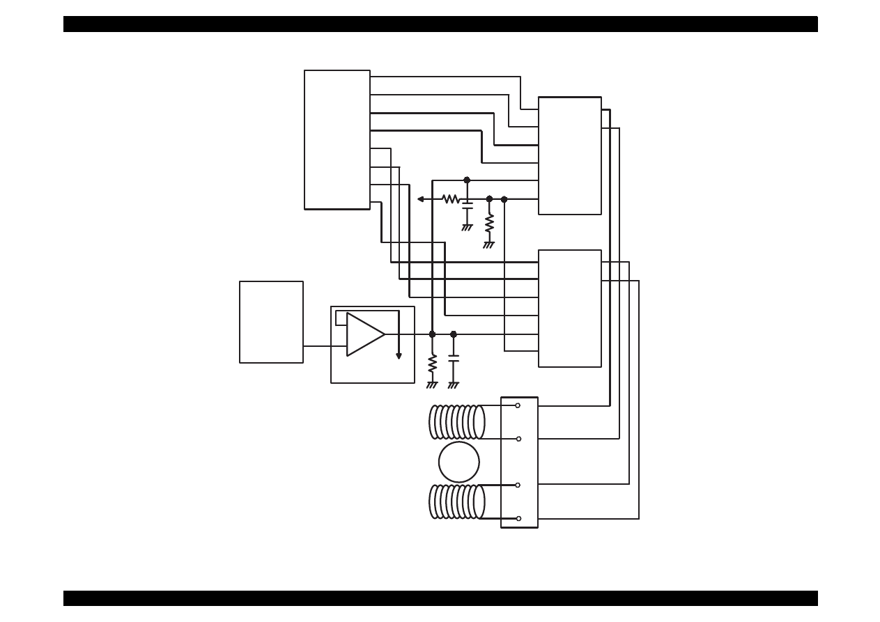
EPSON Stylus Color 440/640/740
Revision A
Chapter 2
Operating Principles
77
Figure 2-37. PF (Pump) Motor Drive Circuit for Stylus Color 740
+5
M6252(IC16)
-
+
7
6
5
C90A05
(IC1)
112
DA1
D0
D1
D2
PHASE
REF
PFD
A3956(IC13)
OUTA
OUTB
VBB
VCC
Current
Detection
D0
D1
D2
PHASE
REF
PFD
A3956(IC13)
OUTA
OUTB
VBB
VCC
4
5
6
7
E05B588(IC2)
PFIB0
PFIB1
PFIB2
PFPHAB
PFIA0
PFIA1
PFIA2
PFPHAA
8
9
10
11
14
9
8
7
2
1
14
9
8
7
2
1
10
15
Rotor
A
/A
B
/B
1
3
2
4
CN8
10
15
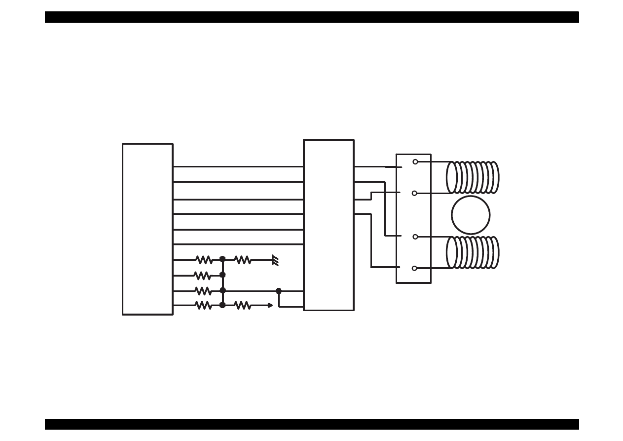
EPSON Stylus Color 440/640/740
Revision A
Chapter 2
Operating Principles
78
2.2.4.8 CR Motor Drive Circuit
IC14(LB1845) on C206 Main-B, C255 Main board, IC14(UDN2917) on
C256 Main board, and IC11(LB1847) on C257 Main board are used for
driving CR motor. In the IC, Bi-pola drive PWM current control type is
performed, making it possible to provide stable current to each phase of
motor. The figures below show carriage motor drive circuit.
Figure 2-38. Carriage Motor Drive Circuit for Stylus Color 440
E05B44
(IC2)
PFAPH
CRA1
CRA0
CRBPH
CRB1
CRB0
CRV0
CRV1
CRV2
CRV3
77
76
75
46
47
48
49
LB1B45
(IC14)
PH1
I11
25
23
I01
22
74
PH2
18
73
I12
20
72
I02
21
Vref1
Vref2
26
17
+5
Out1A
Out1B
Out2A
Out2B
7
6
9
8
Rotor
A
/A
B
/B
1
3
2
4
CN6
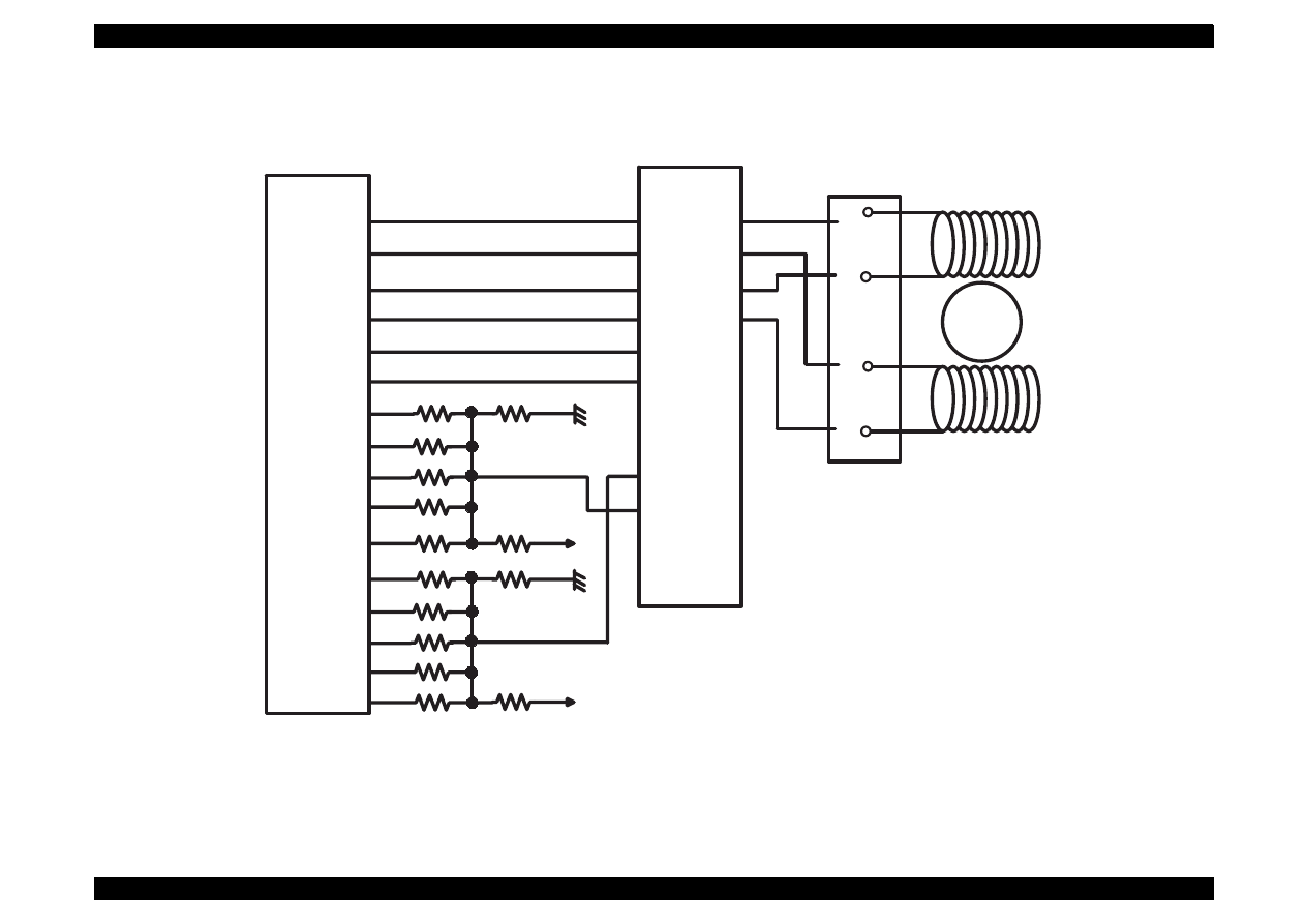
EPSON Stylus Color 440/640/740
Revision A
Chapter 2
Operating Principles
79
Figure 2-39. Carriage Motor Drive Circuit for Stylus Color 640
E05B43
(IC2)
CRA0
CRA1
CRA0
CRB1
CRAPH
CRBPH
MTBV0
MTBV1
MTBV2
MTBV3
MTBV4
75
76
75
60
61
62
63
73
77
74
Rotor
A
/A
B
/B
1
3
2
4
CN5
UDN2917
(IC15)
I10
I11
2
1
I20
23
I21
24
PH1
43
PH2
26
Vref1
Vref2
44
25
Out1A
Out1B
Out2A
Out2B
6
3
18
21
64
+5
65
66
67
70
71
+5
MTAV0
MABV1
MTAV2
MTAV3
MTAV4
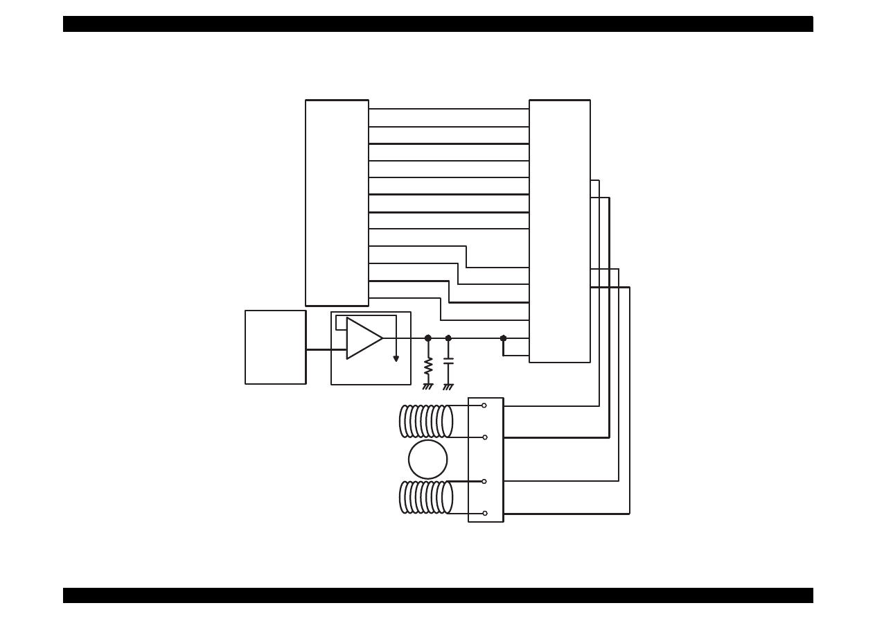
EPSON Stylus Color 440/640/740
Revision A
Chapter 2
Operating Principles
80
Figure 2-40. Carriage Motor Drive Circuit for Stylus Color 740
M6252(IC15)
-
+
1
2
3
C90A05
(IC1)
111
DA0
Current
Detection
E05B588(IC2)
Rotor
A
/A
B
/B
1
3
2
4
CN7
CRENBA
CRENBB
CRPHAA
CRPHAB
192
201
191
202
CRIA0
CRIA1
CRIA2
CRIA3
CRIB0
CRIB1
CRIB2
CRIB3
IA1
IA2
IA3
IA4
IB1
IB2
IB3
IB4
PHASE1
PHASE2
ENBL1
ENBL2
Vref1
Vref2
LB1847(IC11)
17
2
13
26
16
27
25
24
23
22
18
19
20
21
193
194
195
196
200
199
198
197
OUTA
OUTA-
OUTB
OUTB-
7
6
9
8

TROUBLESHOOTING
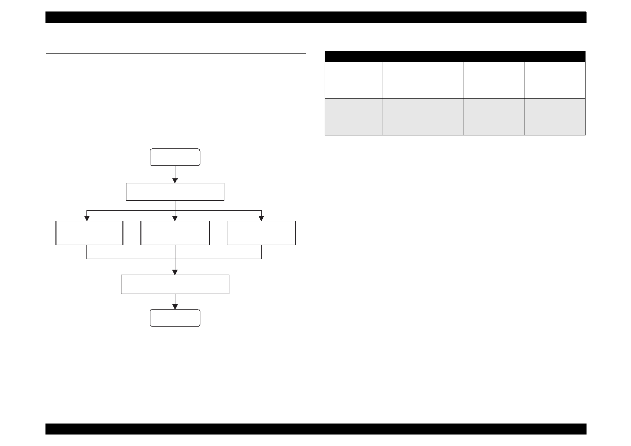
EPSON Stylus Color 440/640/740
Revision A
Chapter 3
Troubleshooting
82
3.1 Troubleshooting
The printer may exhibit different symptoms for the same problem, which
makes troubleshooting more difficult. This section, however, provides
simple and effective ways to facilitate troubleshooting.
The following flowchart illustrates the main steps of the trouble shooting
process.
Figure 3-1. Troubleshooting Process Flowchart
Table 3-1. M otor Resistance and M easurem ent Procedure
* Main board refers to the following:
Stylus Color 440: C206Main-B, C255Main
Stylus Color 640: C256Main
Stylus Color 740: C257Main
See the following page for Table 3-2, “Sensor Check” and Table 3-3,
“Printer Condition and Panel Status”.
START
END
Unit Level Troubleshooting
Unit Repair
(PSB/PSE)
Unit Repair
(Main board)
Disassemble and Adjustment
Unit Repair
(Printer Mechanism)
Motor Name
Location
Check Point
Resistance
CR Motor
• Stylus Color 440/640
CN6 (Main board *)
• Stylus Color 740
CN7 (Main board *)
Pins 1 & 3,
Pins 2 & 4
7.8 Ohms
±
10%
PF (Pump) Motor
• Stylus Color 440/640
CN7 (Main board *)
• Stylus Color 740
CN8 (Main board *)
Pins 1 & 3,
Pins 2 & 4
7.8 Ohms
±
10%
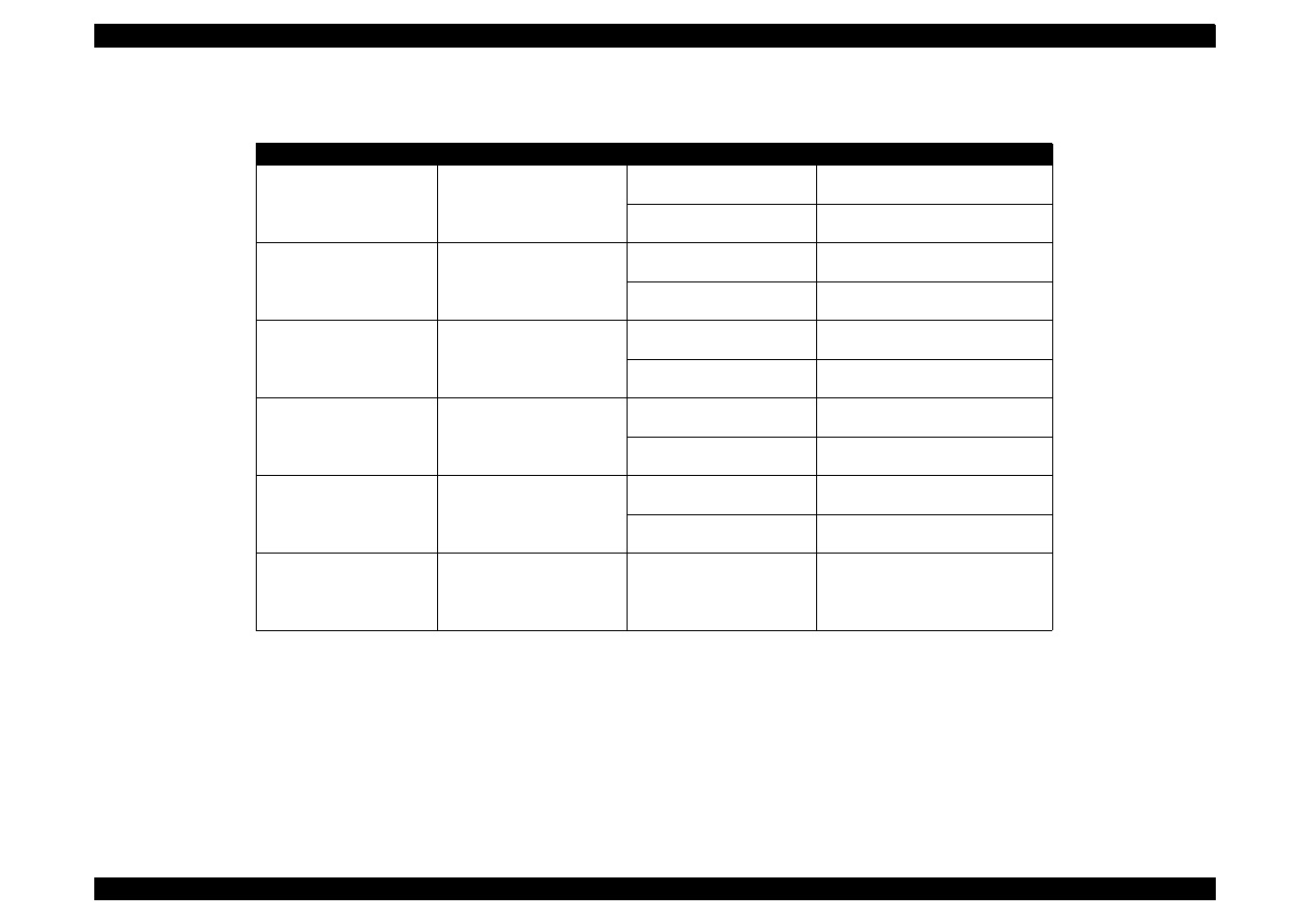
EPSON Stylus Color 440/640/740
Revision A
Chapter 3
Troubleshooting
83
Table 3-2. Sensor Check
Sensor Name
Location
Signal Level
Sensor Status
Paper End Senior
• Stylus Color 440/640
CN4/Pins 1 & 2
Open: less than 0.7 V
Paper loaded
• Stylus Color 740
CN5/Pins 1 & 2
Close: more than 2.4 V
No paper
Carriage Home Position
Sensor
• Stylus Color 440/640
CN5/Pins 1 & 2
Open: less than 0.7 V
Home position
• Stylus Color 740
CN4/ Pins 1 & 2
Close: more than 2.4 V
Out of home position
ASF Phase Sensor
• Stylus Color 440/640
CN11/Pins 1 & 2
Open: less than 0.7 V
Home position
• Stylus Color 740
CN6/ Pins 1 & 2
Close: more than 2.4 V
Out of home position
Black Cartridge Sensor
• Stylus Color 440/640
CN8/ Pins 1 & 18
On: 0V
Black cartridge out
• Stylus Color 740
CN9/Pins 1 & 19
Off: more than 2.4 V
Black cartridge installed
Color Cartridge Sensor
• Stylus Color 440/640
CN8/ Pins 2 & 18
On: 0V
Color cartridge out
• Stylus Color 740
CN9/Pins 2 & 19
Off: more than 2.4 V
Color cartridge installed
Thermistor
• Stylus Color 440/640
CN8/ Pins 3 & 18
Analog data
Change the VH voltage of charge
pulse for common driver circuit
• Stylus Color 740
CN9/ Pins 2 & 19
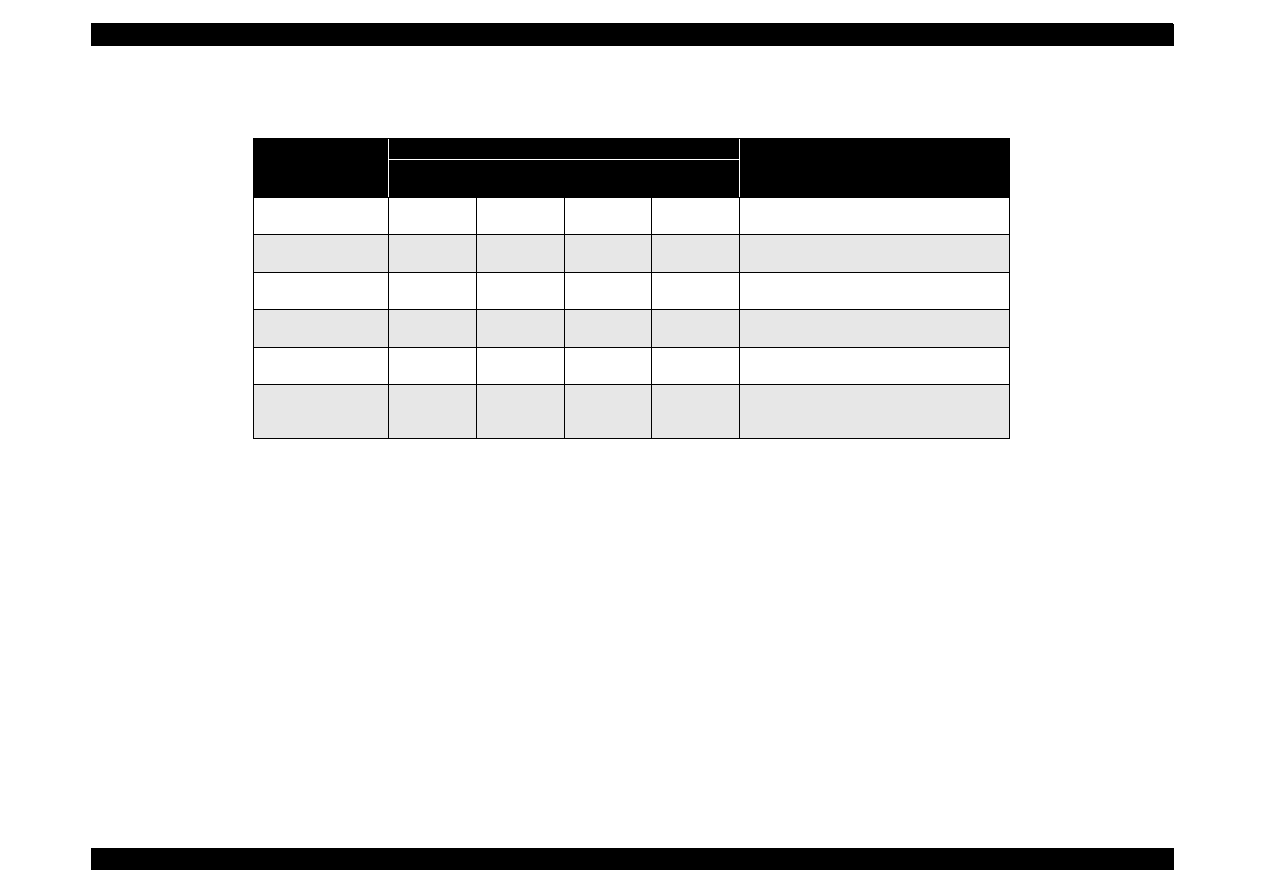
EPSON Stylus Color 440/640/740
Revision A
Chapter 3
Troubleshooting
84
Table 3-3. Printer Condition and Panel Status
Error Status
Indicators
Recovery
Power
Ink out
(Black)
Ink Out
(Color)
Paper Out
Paper Out
---
---
---
On
Load paper by pressing the load/eject
button.
Paper jam condition
---
Off
Off
Blink
Eliminate a paper then press the load/eject
button.
No Ink cartridge or
Ink end (black)
---
On
---
---
Install a new black ink cartridge by pressing
the load/eject button for 3 seconds.
No Ink cartridge or
Ink end (color)
---
---
On
---
Install a new color ink cartridge by pressing
the load/eject button for 3 seconds.
Maintenance
request
Blink
Blink
Blink
Blink
Change the waste ink drain tank and reset
the EEPROM.
Fatal error
Blink
On
On
Blink
Turn the printer off and on again. If the
printer does not recover, repair the
appropriate part.
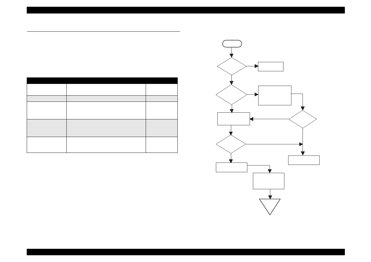
EPSON Stylus Color 440/640/740
Revision A
Chapter 3
Troubleshooting
85
3.2 Unit Level Troubleshooting
When a problem occurs, you can identify the defective unit according to
the symptoms exhibits. The table below lists the symptoms of certain
problems. Once the problem is identified, refer to the flowchart that
corresponds to the problem.
3.2.1 Printer does not operate at power on.
Flowchart 1
Table 3-4. Symptom and Problem
Symptom
Problem
Flowchart No.
Printer does not
operate at power on.
LEDs do not light.
Printer mechanism does not operate.
Flowchart 1
Error is detected
Error is indicated by LED indication.
Flowchart 2
Failure occurs
during printing.
Printing is not performed.
Abnormal printing (missing dot, etc.)
Print quality is poor.
Flowchart 3
Printer does not
feed paper correctly.
No paper is fed.
Paper feed is irregular.
Paper jam occurs.
Flowchart 4
Control panel
operation is
abnormal.
No response to button access.
Flowchart 5
Is AC
power voltage
normal?
YES
Is the
fuse(F1) of
power supply
Is the
output voltage
of power supply
normal?
Exchange the main
board.
NO
Input normal
power supply.
NO
Exchange the fuse.
Disconnect CN10 in
the main board and
turn the power on
again.
YES
Check output voltage
of CN2 in the power
supply board.
Exchange the power
supply board
Check the motor and
head. Refer to the
repair item of the
printer mechanism.
START
END
YES
NO
board
opened?
YES
Is the
fuse opend
again?
NO

EPSON Stylus Color 440/640/740
Revision A
Chapter 3
Troubleshooting
86
3.2.2 Error is detected
Flowchart 2
3.2.3 Failure occurs during printing
Flowchart 3
START
Check the error
message.(Refer to
Table 3-3)
Is it a carriage
error?
Is it an ink
cartridge
error?
Maintenance Error
Replace the waste
ink absorber and reset
the counter.
(Refer to 1.4.2)
NO
NO
Turn off the printer,
and move the carriage
by hand.
Yes
Replace the ink-
cartridge with a
new one.
Yes
Does the error
appear again?
Check the ink cartridge
sensor and replace
the head if it's ubnormal.
END
Does the carriage
move smoothly?
Yes
Check CR motor.
Replace the main
board if there is no
problem.
Is the problem
solved?
Refer to Section 3.4
"Repair of the printer
mechanism".
END
NO
Yes
NO
Yes
NO
START
Is printing
carried out
O.K?
Is print
quality
normal?
Is the
problem
solved?
Perform printing
adjustment.
(Refer to Chapter5)
Replace the ink
cartridge with a new
one and perform
self-test.
Is the
problem
solved?
Refer to 3.4 2Repair of
the printer-mechanism".
Is the
END
END
Are all
cables connected
to the main
board?
Perform cleaning
Connect them.
Is the
Refer to 3.4 "Repair of
the printer-mechanism".
Is the
END
Replace the Main
board
NO
YES
NO
NO
YES
YES
NO
YES
YES
NO
YES
NO
YES
NO
YES
Perform self-
test printing
problem
solved?
problem
solved?
problem
solved?
NO
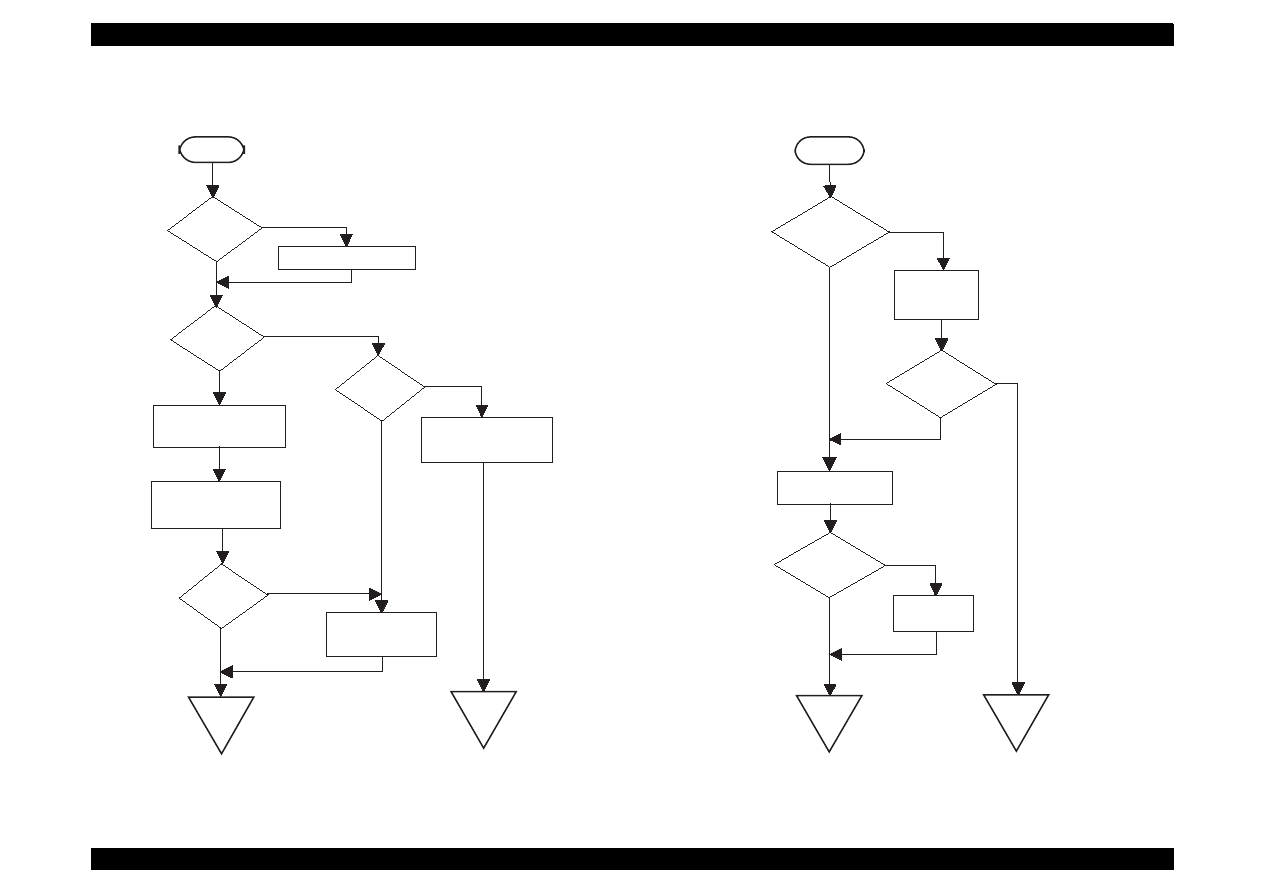
EPSON Stylus Color 440/640/740
Revision A
Chapter 3
Troubleshooting
87
3.2.4 Printer does not feed paper correctly.
Flowchart 4
3.2.5 Control panel operation is abnormal.
Flow Chart 5
START
Is
paper set
in the ASF
correctly?
Do
the PF roller
and platen
rotate?
Remove any obstruction
in the paper path if
there is any.
Clean the roller of
paper path.
Is the
Is the
PF motor
running?
Refer to Section 3.4
"Repair of the printer
mechanism".
END
Check the PF motor.
If there is no problem,
replace the main board.
END
NO
YES
NO
YES
YES
NO
Set the paper correctly
NO
problem
solved?
START
Is the
control panel
connected
correctly?
Connect the
control panel
correctly.
Is the
problem
solved?
Replace the control
panel.
Is the
problem
solved?
END
Replace the
main board.
END
YES
NO
NO
YES
NO
YES

EPSON Stylus Color 440/640/740
Revision A
Chapter 3
Troubleshooting
88
3.3 Unit Repair of Power Supply Board
Note:
The power supply board equipped with each printer is as follows:
S
tylus Color 440: C206 PSB/PSE
Stylus Color 640: C206 PSB/PSE
Stylus Color 740: C257 PSB/PSE
This section describes the problems related to the power supply board.
The table below provides various symptoms, likely causes, and
checkpoints. The checkpoints refer to waveforms, resistance, and other
values to check to evaluate the operation of each component.
EPSON Stylus Color 440/640/740
Revision A
Chapter 3
Troubleshooting
89
Table 3-5. Repair of the C206/C257 PSB/PSE Board
Symptom
Condition
Cause
Checkpoint
Solution
The printer does
not operate at all.
+42V line is dead.
F1 is open.
Check F1 by using a
tester.
Replace F1.
Transformer coils are open.
Check the waveform at the drain of Q1.
Replace T1.
Switching FET (Q1) is
dead.
Check drain side.
Replace Q1.
Feed back transistor (Q2,
Q3) are dead.
Check collector side.
Replace Q2 or Q3.
+42 V line is abnormal.
Check the following parts.
• ZD87, ZD83
• ZD51, ZD81–ZD86
• PC1
Replace suitable
parts.
EPSON Stylus Color 440/640/740
Revision A
Chapter 3
Troubleshooting
90
(Continued)
The printer does
not operate at all.
+5V line is dead.
IC51 (L4962E/FA3635P) is
dead.
Note:
• L4962 is used for Stylus
Color 440/640.
• FA3635P is used for
Stylus Color 740.
Stylus Color 440/640:
• Check the oscillation
(Pin 5) waveform of
IC51.
(Pin 5)
• Check the switching
(Pin 7) waveform of
IC51.
(Pin 7)
Replace IC51.
IC51 (L4962E/FA3635P) is
dead.
Note:
• L4962 is used for Stylus
Color 440/640.
• FA3635P is used for
Stylus Color 740.
Stylus Color 740:
• Check the switching
(Pin 8) waveform of
IC51.
(Pin 8)
Replace IC51.
Table 3-5. Repair of the C206/C257 PSB/PSE Board
Symptom
Condition
Cause
Checkpoint
Solution

EPSON Stylus Color 440/640/740
Revision A
Chapter 3
Troubleshooting
91
3.4 Unit Repair of the Main Board
Note:
The Main board equipped with each printer is as follows:
Stylus Color 440:
C206MAIN-B, C255MAIN
Stylus Color 640:
C256MAIN
Stylus Color 740:
C257MAIN
This section describes the problems related to the main controller
board. The table below provides various symptoms, likely causes, and
checkpoints. The check points refer to waveforms, resistance, and other
values to check to evaluate the operation of each component.
EPSON Stylus Color 440/640/740
Revision A
Chapter 3
Troubleshooting
92
Table 3-6. Unit Repair of Main Board
Symptoms
Condition
Cause
Check Point
Solution
The printer does not
operate at all.
(Continues to the next
page.)
CPU does not operate.
(Continues to the next
page.)
The reset circuit does not
operate.
Stylus Color 440, 640:
Check the waveform of the
+5V and /Reset signal
(IC9=Pin 7, 6-pin)
Replace IC9.
Stylus Color 740:
Check the waveform of the
+5V and /Reset signal
(IC8=2-pin, Pin 7)
Replace IC8.
Control ROM, D- RAM,
and Mask ROM are not
selected correctly or it’s
dead.
(Continues to the next
page.)
Stylus Color 440:
If you can not find the waveform at 88-pin of IC1, the IC1 is
dead, and if you can not find it at 20-pin of IC3 or 26-pin of
IC4, the IC3 or IC4 is dead.
Stylus Color 440:
Replace IC1, IC3, or IC4.
Stylus Color 640:
If you can not find the waveform at 97-pin of IC1, the IC1 is
dead, and if you can not find it at 13-pin of IC3, the IC3 is
dead. If you can not find the waveform at 98, 99-pin of IC1,
the IC1 is dead, and if you can not find it at 27-pin of IC5, and
at 14-pin of IC6, the IC5 or IC6 is dead.
Stylus Color 640:
Replace IC1, IC3, IC5, or IC6
EPSON Stylus Color 440/640/740
Revision A
Chapter 3
Troubleshooting
93
(Continued)
The printer does not
operate at all.
(Continued)
CPU does not operate.
(Continued)
Stylus Color 740:
• If you can not find the waveform at 2, 128, 127-pin of IC1,
the IC1 is dead, and if you can not find the waveform at 85-
pin of IC2, the IC2 is dead.
• If you can not find the waveform at 13-pin of IC3, the IC3 is
dead.
• If you can not find the waveform at 27-pin of IC4 or IC5, the
IC4 or IC5 is dead.
• If you can not find the waveform at 14-pin of IC6, the IC6 is
dead.
Stylus Color 740:
• Replace IC1, or IC2.
• Replace IC3.
• Replace IC4 or IC5.
• Replace IC6.
Stylus Color 440:
CRU2 is dead.
Stylus Color 640:
CR2 is dead.
Stylus Color 740:
CR1 or IC2 is dead.
Stylus Color 440, 640:
Check the waveform at
27,28-pin of IC1.
Stylus Color 740:
Check the waveform at
118 or 119-pin of IC2.
And check the output
waveform at 91-pin of
IC2.
Stylus Color 440, 640:
Replace CRU2 or CR2.
Stylus Color 740:
Replace CR1 or IC2.
The carriage does not
operate normally.
(Continues to the next
page.)
Carriage motor does not
operate at all or it occurs a
abnormal noise.
(Continues to the next
page.)
IC2 is dead.
Stylus Color 440:
Check the waveform at
25, 18 pin of IC14.
Stylus Color 640:
Check the waveform at
43, 26 pin of IC14.
Stylus Color 740:
Check the waveform at
27, 16 pin of IC11.
Replace IC2.
Table 3-6. Unit Repair of Main Board
Symptoms
Condition
Cause
Check Point
Solution
EPSON Stylus Color 440/640/740
Revision A
Chapter 3
Troubleshooting
94
(Continued)
The carriage does not
operate normally.
(Continued)
Carriage motor does not
operate at all or it occurs a
abnormal noise.
Stylus Color 440, 640:
IC14 is dead.
Stylus Color 740:
IC11 is defective.
Stylus Color 440:
Check the waveform at 6-9
pin of IC14.
Stylus Color 640:
Check the waveform at 3, 6,
18, 21 pin of IC14.
Stylus Color 740:
Check the waveform at 6-9
pin of IC11.
Stylus Color 440, 640:
Replace IC14.
Stylus Color 740:
Replace IC11.
Printing is abnormal.
Printing is not execute.
Trapezoidal waveform
does not output.
Stylus Color 440:
Check the trapezoidal waveform at 3-pin of Q7 or Q9 on
C206Main-B, C255 main board.
Stylus Color 640:
Check the trapezoidal waveform at 3-pin of Q7 or Q9 on
C256 Main board.
Stylus Color 740:
Check the trapezoidal waveform at 3-pin of Q2 or Q3 on
C257 Main board.
Stylus Color 440:
Replace IC6, Q7, or Q9.
Stylus Color 640:
Replace IC7, Q7, or Q9.
Stylus Color 740:
Replace IC14, Q2, or Q3.
IC2 is dead.
Stylus Color 440, 640:
Check the clock signal of
trapezoidal from IC2. (at
80 pin of IC2)
Stylus Color 740:
Check the clock signal of
trapezoidal from IC2. (at
174 pin of IC2)
Replace IC2.
Table 3-6. Unit Repair of Main Board
Symptoms
Condition
Cause
Check Point
Solution
EPSON Stylus Color 440/640/740
Revision A
Chapter 3
Troubleshooting
95
Paper feed operation is
abnormal.
Paper feed motor does not
work.
IC2 is dead.
Stylus Color 440:
Check the waveform at
25, 18 pin of IC14.
Stylus Color 640:
Check the waveform at
43, 26 pin of IC16.
Stylus Color 740:
Check the waveform at
Pin 7 of IC12 and IC13.
Replace IC2
Stylus Color 440, 640:
IC15 is dead.
Stylus Color 740:
IC12 or IC13 is
dead.
Stylus Color 440:
Check the output
waveform of at 6-9 pin of
IC15.
Stylus Color 640:
Check the output
waveform of at 3,
6,18,21pin of IC15.
Stylus Color 740:
Check the output
waveform of at 10, 15
pin of IC12 and IC13.
Stylus Color 440, 640:
Replace IC15
Stylus Color 740:
Replace IC12, IC13.
Table 3-6. Unit Repair of Main Board
Symptoms
Condition
Cause
Check Point
Solution
EPSON Stylus Color 440/640/740
Revision A
Chapter 3
Troubleshooting
96
3.5 Repair of the Printer Mechanism
This section provides instruction for repairing the printer mechanism. It
describes various problems, symptom, likely causes, checkpoints, and
solutions. Select appropriate symptom from the table and check each
parts and its function as described in the checkpoint.
Table 3-7. Repair of the Printer Mechanism
Symptom
Condition
Cause
Check Point
Solution
Abnormal pump
mechanism operation
Abnormal PF motor
operation when the
power is turned on.
Foreign substances are
loaded in the PF gears.
Manually drive the platen drive gear and
check it if it rotates normally.
Remove any foreign substances.
The PF motor is defective.
(Refer to Table5-1)
Check the inner coil resistance and see if
there is any disconnection of the coil.
Exchange the PF motor.
Ink is not absorbed or is
poorly absorbed.
Used ink does not go
through the waste ink
tube.
The pump tube is crashed.
Check the tube visually.
Fix the crashed part by the airgun.
Capping rubber is
damaged or deformed.
Check the capping rubber visually.
Replace the cap mechanism.
The tube is out of the cap.
Check if the tube is out of the cap visually.
Connect the tube properly.
Pump bulb is not closed at
absorption.
Check the bulb operation visually.
Replace the cap mechanism.
Abnormal carriage
operation.
Abnormal carriage
operation at power on.
Foreign substance in the
CR drive gear.
Check visually if there is any substances or
not.
Remove any foreign substances.
CR motor is defective.
Check the inner coil resistance and see if
there is any disconnection of the coil.
Replace the CR motor.
Abnormal carriage
operation during
printing.
Carriage movement is not
smooth.
Check whether the carriage moves
smoothly when moved manually.
Clean and lubricate the carriage
guide axis.
Check tension of the timing belt.
Adjust tension mechanism or
exchange it.
Check if there is any foreign substances in
the carriage path.
Remove any foreign substances.
Printing is not
performed.
The carriage moves,
but no printing is
performed.
Head FFC is out of
connection.
Check if the head FFC on the board or
carriage is connected surely.
Connect the FFC properly.
The FFC is disconnected
inside.
Check the FFC by using a tester.
Replace the FFC.
I/C is defective.
Install a new I/C and perform the self-test.
Replace I/C.
Head unit is defective.
If the condition does not improve even after
2or 3 times cleaning operation, replace the
head unit and perform the self-test.
Replace the head unit.
EPSON Stylus Color 440/640/740
Revision A
Chapter 3
Troubleshooting
97
Abnormal printing
Only a particular dot
causes abnormal
printing.
Print head surface is not
clean.
(dot missing)
Perform the cleaning operation several
times and check printing.
Perform the cleaning.
The head unit is defective.
Perform the cleaning operation several
times and check printing.
If condition does not improve even
after the cleaning, replace the head.
Capping absorber is
touching the head surface.
Check the head absorber visually.
Replace the head absorber if it is
deformed.
A dot is not printed
occasionally.
Print head surface is not
clean. (dot-missing)
Perform the cleaning operation several
times and check printing.
Perform the cleaning.
The head FFC is
disconnected inside.
Check the FFC by using a tester.
Replace the head FFC.
The head FFC is out of
connection.
Check if the head FFC on the board or
carriage is connected surely.
Connect the FFC properly.
The head unit is detective.
Perform the cleaning operation several
times and check printing.
If condition does not improve even
after the cleaning, replace the head.
I/C is defective.
Install the new I/C and perform self-test.
Replace I/C.
Black specks or dots.
The head FFC is out of
connection.
Check if the head FFC on the board or
carriage is connected surely.
Connect the FFC properly.
The head unit is detective.
Check connection with the head FFC.
Replace the head if there is no
connection problem with the FFC.
A vertical line is not
aligned.
Bi-directional alignment is
not adjusted.
Perform Bi-D adjustment.
Refer to Chapter4.
White line appears in
the image data.
Head angle is not correct.
Perform head angle adjustment.
Refer to Chapter4.
Platen gap is not correct.
Perform platen gap adjustment.
Refer to Chapter4.
Dot shooting direction is
tilted because head
surface is not clean
Perform the cleaning operation several
times and check printing.
Perform the cleaning operation.
I/C is defective.
Install a new I/C and perform the self-test.
Replace I/C.
Head unit is defective.
Perform the cleaning operation several
times and check printing.
Replace the head unit.
Table 3-7. Repair of the Printer Mechanism
Symptom
Condition
Cause
Check Point
Solution
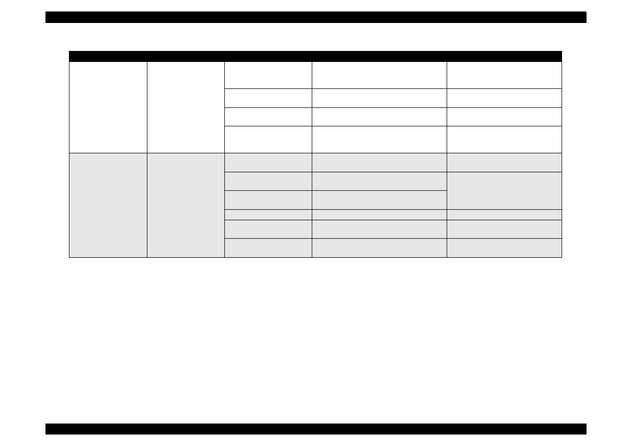
EPSON Stylus Color 440/640/740
Revision A
Chapter 3
Troubleshooting
98
Abnormal paper
feeding.
Paper is not fed.
Friction of the PF roller.
Check if the PF roller rotates when paper is
not fed.
Clean the PF roller by the cleaning
sheet. Replace the PF roller if it
does not recover.
Abnormal operation of the
hopper.
Check movement of the ASF hopper
visually.
Replace ASF.
Malfunction of ASF drive
change-over.
Check if the ASF gear rotates visually.
Replace gears of the ASF drive
change-over.
Friction of the PF roller.
Check if the PF roller slips during paper
feeding.
Clean the PF roller by the cleaning
sheet. Replace the PF roller if it
does not recover.
Printer stops during
initialization.
Fatal error appears.
ASF sensor is defective.
Check the signal level of the ASF sensor.
(Refer to Table 5-2)
Replace ASF sensor.
PE sensor is defective.
Check the signal level of the PE sensor.
(Refer to Table 5-2)
Replace PE sensor.
HP sensor is defective.
Check the signal level of the HP sensor.
(Refer to Table 5-2.)
Head FFC is disconnected.
Check if the head FFC is connected.
Connect the head FFC.
CR motor is defective.
Check the CR motor cable is connected.
Replace the CR motor if there is no
problem in the cable connection.
PF motor is defective.
Check if the PF motor cable is connected.
Replace the PF motor if there is no
problem in the cable connection.
Table 3-7. Repair of the Printer Mechanism
Symptom
Condition
Cause
Check Point
Solution

DISASSEMBLY AND ASSEMBLY

EPSON Stylus Color 440/640/740
Revision A
Chapter 4
Disassembly and Assembly
100
4.1 Overview
This chapter describes procedures for disassembling the main
components of EPSON Stylus Color 440/640/740. Unless otherwise
specified, disassembly units or components can be reassembled by
reversing the disassembly procedure. Therefore, no assembly
procedures are included in this chapter. Precautions for any
disassembly or assembly procedure are described under the heading
“CHECK POINT”. Any adjustments required after disassembling the
units are described under the heading “REQUIRED ADJUSTMENT”.
4.1.1 Precautions for Disassembling the Printer
See the precautions given under the heading “WARNING” and
“CAUTION” in the right column and the following page, respectively,
when disassembling or assembling EPSON Stylus Color 440/640/740.
W A R N I N G
Disconnect the power cable before disassembling or
assembling the printer.
Wear protective goggles to protect your eyes from
ink. If ink gets in your eye, flush the eye with fresh
water and see a doctor immediately.
If ink comes into contact with your skin, wash it off
with soap and water. If irritation occurs, contact a
physician.
A lithium battery is installed on the main board of this
printer. Be sure to observe the following instructions
when serving the battery:
Keep the battery away from any metal or other
batteries so that electrodes of the opposite polarity do
not come in contact with each other.
Do not heat the battery or put it near fire.
Do not solder on any part of the battery. (Doing so may
result in leakage of electrolyte from the battery,
burning or explosion. The leakage may affect other
devices close to the battery.)
Do not charge the battery. (An explosion may be
generated inside the battery, and cause burning or
explosion.)
Do not dismantle the battery. (The gas inside the
battery may hurt your throat. Leakage, burning or
explosion may also be resulted.)
Do not install the battery in the wrong direction. (This
may cause burning or explosion.)
Danger of explosion if the battery is incorrectly
replaced. Replace only with the same or equivalent
type recommended by the manufacture. Dispose the
used batteries according to government’s law and
regulations.
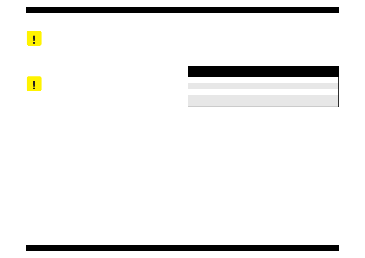
EPSON Stylus Color 440/640/740
Revision A
Chapter 4
Disassembly and Assembly
101
4.1.2 Tools
Table 4-1 lists the tools recommended for disassembling, assembling,
or adjusting the printer. Use only tools that meet these specifications.
C A U T I O N
Risque d’explosion si la pile est remplacée
incorrectment. Ne remplacer que par une pile du même
type ou d’un type équivalent recommandé par le
fabricant. Eliminer les piles déchargées selon les lois
et les règles de sécurité en vigueur.
C A U T I O N
Never remove the ink cartridge from the carriage
unless this manual specifies to do so.
When transporting the printer after installing the ink
cartridge, be sure to pack the printer for
transportation without removing the ink cartridge.
Use only recommended tools for disassembling,
assembling or adjusting the printer.
Apply lubricants and adhesives as specified. (See
Chapter 6 for details.)
Make the specified adjustments when you
disassemble the printer.
(See Chapter 4 for details.)
When assembling, if an ink cartridge is removed and
needs to be installed again, be sure to install a new
ink cartridge because of the following reasons;
Once the ink cartridge mounted on the printer is
removed, air comes into and creates bubbles in the
cartridge. These bubbles clog ink path and cause
printing malfunction.
If an ink cartridge in use is removed and is reinstalled,
ink quantity will not be detected correctly since the
counter to check ink consumption is cleared.
Because of the reasons above, make sure to return
the printer to the user with a new ink cartridge
installed.
Table 4-1. Tool List
Tools
Commercially
Available
Code
(+) Driver No.2
O.K.
B743800200
(+) Driver No.1
O.K.
B743800400
Tweezers
O.K.
B741000100
Hexagon Box Driver
(Opposite side:5.5mm)
O.K.
B741700100
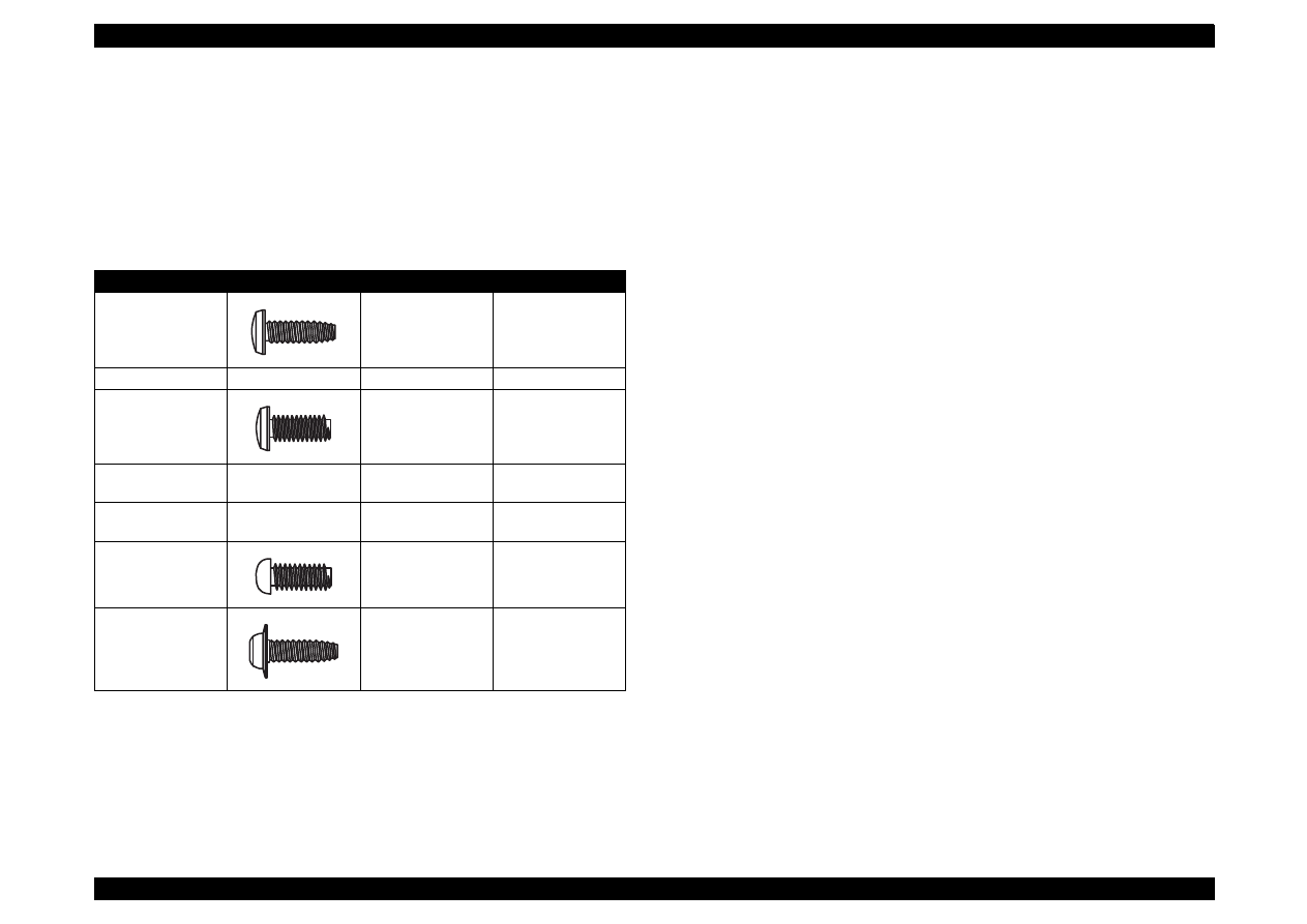
EPSON Stylus Color 440/640/740
Revision A
Chapter 4
Disassembly and Assembly
102
4.1.3 Specification for Screws
Table 4-2 shows screw specifications. During assembly and
disassembly, make sure that the specified types of screws are used at
proper locations, referring to the table below. Note that the screw
numbers described in the manual correspond to the numbers in the
table.
Table 4-2. Screw Characteristic
No.
Body
Name
Size
1
+Bind, S-tight
M3X6
2
+Bind, S-tight
M3X10
3
+Bind, P-tight
(CBP tight)
M3X6
4
+Bind, P-tight
(CBP tight)
M3X10
5
+Bind, P-tight
(CBP tight)
M3X8
6
+Pan head
(CP)
M3X4
7
+Bind, S-tight,
Sems
R2(CBS Sems)
M3X6
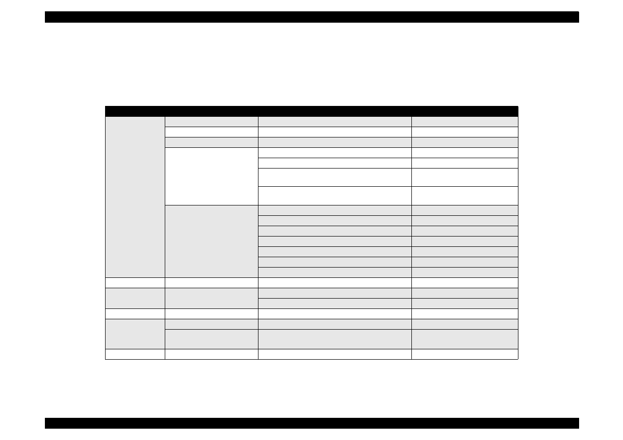
EPSON Stylus Color 440/640/740
Revision A
Chapter 4
Disassembly and Assembly
103
4.1.4 Service Checks After Repair
Before returning the printer after servicing, use the check list below,
which enables you to keep record of servicing and shipping more
efficiently.
Table 4-3. Inspection Checklist for the Repaired Printer
Category
Component
Item to check
Is Check Required?
Printer units
Self-test
Is the operation normal?
Checked /
Not necessary
On-line test
Was the on-line test successful?
Checked /
Not necessary
Print head
Is ink ejected normally from all nozzles?
Checked /
Not necessary
Carriage
mechanism
Does the carriage move smoothly?
Checked /
Not necessary
Any abnormal noise during movement?
Checked /
Not necessary
Any dirt or obstacles around the shaft of carriage
guide?
Checked /
Not necessary
Is the CR motor at the correct temperature
(not over heating)?
Checked /
Not necessary
Paper feeding
mechanism
Is paper fed smoothly?
Checked /
Not necessary
Does paper get jammed?
Checked /
Not necessary
Does paper get skew during paper feeding?
Checked /
Not necessary
Are papers multi fed?
Checked /
Not necessary
Does the PF motor get overheated?
Checked /
Not necessary
Abnormal noise during paper feeding?
Checked /
Not necessary
Is the paper path clear of all obstructions?
Checked /
Not necessary
Adjustment
Specified adjustment items
Are adjusted conditions all right?
Checked /
Not necessary
Lubricant
Specified lubricated item
Is lubrication applied to the specified locations?
Checked /
Not necessary
Is the quantity of lubrication adequate?
Checked /
Not necessary
Function
ROM version
Newest version:
Checked /
Not necessary
Shipment
package
Ink cartridges
are the ink cartridges installed correctly?
Checked /
Not necessary
Protection conditions during
transport
Is all the pointed parts firmly fixed?
Checked /
Not necessary
Others
Attached items
Are all attached items from users included?
Checked /
Not necessary
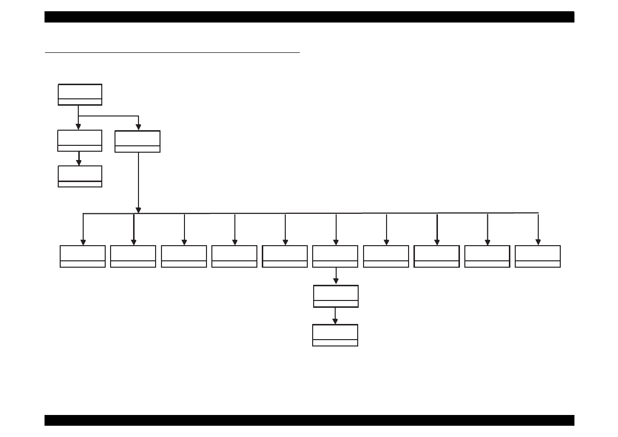
EPSON Stylus Color 440/640/740
Revision A
Chapter 4
Disassembly and Assembly
104
4.2 Disassembly Procedures
The flowchart below shows procedures for disassembly.
Figure 4-1. Flowchart of Disassembly
Remove
the Housing
3.2.1
Remove the
Board Assembly
3.2.2
Remove the
operation panel
3.2.3
Remove the
Printer Mechanism
3.2.4
Refer to
Remove
the Print Unit
3.2.4.1
Remove
the Absorber tray,
Assembly;A
3.2.4.2
Remove the Pump
Assembly,
Cap Assembly
3.2.4.3
Remove the CR
Motor Assembly
3.2.4.4.
Remove the PF
Motor Assembly
3.2.4.5
Remove the ASF
Assembly
3.2.4.6
Remove the Paper
Feed Roller
Assembly
3.2.4.6.1
Remove the LD
Roller Assembly
(Right/Left)
3.2.4.6.2
Remove the CR
Assembly
3.2.4.7
Remove the PF
Roller Assembly
3.2.4.8
Remove the PE
Paper Detector
Assembly
3.2.4.9
Remove the HP
Detector
3.2.4.10
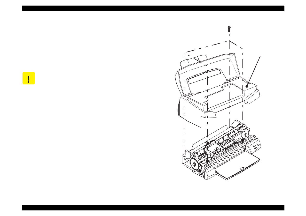
EPSON Stylus Color 440/640/740
Revision A
Chapter 4
Disassembly and Assembly
105
4.2.1 Removing the Housing
Since the printer mechanism itself structures the bottom part, the printer
mechanism appears just by removing the housing.
1. Open the printer cover and turn the PG adjustment lever towards (+)
side.
2. Remove 4 screws (No.2) securing the housing, and remove the
housing.
Figure 4-2. Removing the Housing
C A U T I O N
Lift up and remove the housing, pulling it towards you.
(Since it collides with carriage)
(No.2)
Housing
EPSON Stylus Color 440/640/740
Revision A
Chapter 4
Disassembly and Assembly
106
4.2.2 Removing the Board Assembly
Since the main board and power supply circuit board are built in a
separate bracket from the printer mechanism, remove the whole
bracket from the printer mechanism.
NOTE: The main board and power supply board equipped with each
printer are as follows
- S
tylus Color 440:C206MAIN-B, C255 Main, C206PSB/PSE
- Stylus Color 640:C256MAIN, C206PSB/PSE
- Stylus Color 740:C257MAIN, C257PSB/PSE
1. Remove the housing.(Refer to 3.2.2)
2. Remove the 5 screws(No.1) securing the “M/B Shield plate” on the
printer mechanism.
3. Pull out the “M/B Shield Plate” a little bit and remove cables which
are hung on the A and B holders as you can see in the figure below.
Then, take all cables out of connectors on the main board.
Stylus Color 440, 640:
CN11 black, CN4 yellow, CN5 white, CN3 black, CN6/7 white,
CN8 FFC black
Stylus Color 740:
CN11 black, CN4 white, CN5 yellow, CN6 black, CN 7/8 white,
CN9 FFC gray
4. After removing all the cables from the main board, detach the
“Shield plate M/B” completely from the printer mechanism.
5. When removing each board unit from the “M/B Shield plate”, remove
the screws securing each unit and shield plate. [main board: 10
screws (7 No.1 screws, 3 No.6 screws), power supply board: 4
screws (No.1)] Refer to the next page for the figure. Also, when
removing the power supply board, remove the cable connecting to
the main board (CN6 with lock device).
C A U T I O N
Since the connectors CN 6,7,10(for 440, 640) and
CN7,8,10(for 740) have connector locks, be sure to
release the locks before removing the cables. Also,
make sure to lock when connecting these cables.
When connecting cables to the connectors, the
cables never cross with each other in this printer. So,
if there are two connectors sitting next to each other,
the cable on the right should be connected to the
right connector and the cable on the left should be
connected to the left one
A D J U S T M E N T
R E Q U I R E D
Be sure to perform the following adjustments when the
Main board is replaced;
1. Head voltage ID Input (Refer to Chapter 5.)
2. Bi-D adjustment (Refer to Chapter 5.)
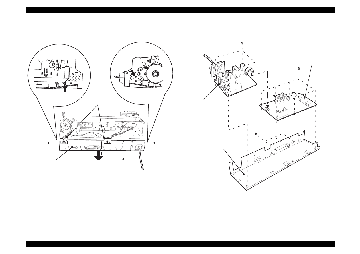
EPSON Stylus Color 440/640/740
Revision A
Chapter 4
Disassembly and Assembly
107
Figure 4-3. Removing the M/B Shield Plate
Figure 4-4. Removing the Boards
[Cable Holder A and B]
A
M/B Shield Plate
(No.1)
(No.1)
(No.1)
B
M/B Shield plate
Power Supply Board
Main Board
(No.6)
(No.1)
(No.1)
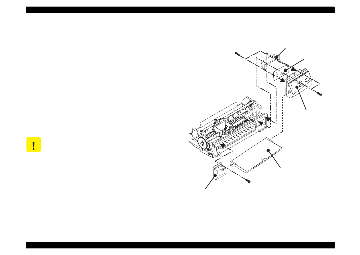
EPSON Stylus Color 440/640/740
Revision A
Chapter 4
Disassembly and Assembly
108
4.2.3 Removing the Operation Panel
The panel board equipped with each printer is as follows:
- Stylus Color 440/640:
C206PNL
- Stylus Color 740:
C209PNL
1. Remove the housing. (Refer to Section 4.2.1.)
2. Remove two screws (No.1) securing the operation panel and
disconnect the operation panel from the printer mechanism.
3. Remove one screw (No.1) and detach the left panel housing.
4. Remove screws (No.3) securing the panel board assembly and
remove C206/209 PNL board from the panel assembly.
5. Disconnect the FFC from the connector on the C206/209 PNL
board.
Figure 4-5. Removing the Operation Panel
C A U T I O N
Removing the operation panel also separates the
stacker assembly, since the operation panel is
attached to the stacker assembly.
S t a c k e r A s s e m b l y
L e f t P a n e l H o u s i n g
P a n e l A s s e m b l y
P a n e l S h i e l d P l a t e
P a n e l B o a r d A s s e m b l y
( N o . 1 )
( N o . 3 )
( N o . 1 )
EPSON Stylus Color 440/640/740
Revision A
Chapter 4
Disassembly and Assembly
109
4.2.4 Disassembling the Printer Mechanism
Since Stylus Color 440/640/740 do not have the lower housing, the
printer mechanism part should already appear by now. Therefore, this
section explains procedures for disassembling the major parts or units
of the printer mechanism.
4.2.4.1 Removing the Print Head Unit
1. Remove the housing. (Refer to Section 4.2.1.)
2. Rotate the flat gear 67.2 towards yourself (front) and release the
carriage lock mechanism. Then move the carriage to the left edge.
3. Take both black and color ink cartridges out of the printhead unit.
4. Remove the blue covers for black and color ink cartridges from the
carriage assembly.
5. Remove the torsion spring 49 and one screw (No.3) and take the
fastener head out.
6. Remove the FFC being placed on the carriage assembly, and
remove the printhead unit from the carriage.
7. Disconnect the FFC from the connector on the drive board built in
the printhead unit.
See the following pages for the figures below:
Figure 4-6, “Removing the Print Head”
Figure 4-7, “Installing the Printhead”
C H E C K
P O I N T
Make sure that the earth board is installed to the
carriage correctly. (There are 2 pins to determine the
location.)
When you install the printhead to the carriage, make
sure that the location pin on the carriage side is placed
in the notch of the printhead.
C A U T I O N
Since the ink cartridge once taken out can not be
used again, be sure to install a new ink cartridge
when you return the printer to the user.
When you return the printer to the user, be sure to
pack the printer for transportation with a new ink
cartridge installed and the carriage in the home
position when the printer is turned on.
A D J U S T M E N T
R E Q U I R E D
When you replace the printhead unit, perform the
following adjustment. (Refer to Chapter 5 for more
details.):
1. Initial ink charge (Refer to Chapter 5/Section 5.2.2.3)
2. Head Voltage ID Input (Refer to Chapter 5/Section
5.2.2.7.)
3. Head Angular Adjustment (Refer to Chapter 5/
Section 5.2.2.8.)
4. Bi-D Adjustment (Chapter 5 /Section 5.2.2.9)
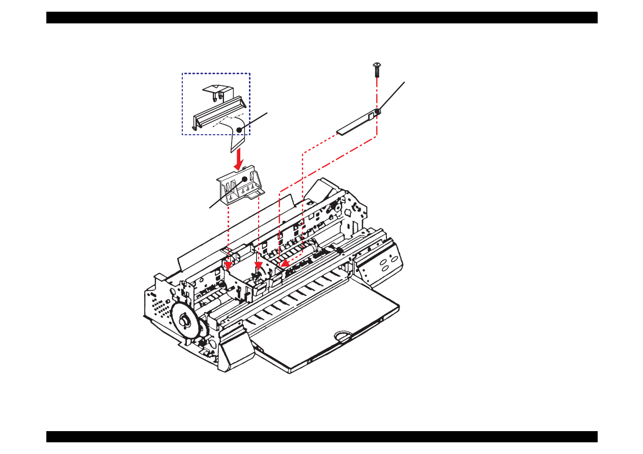
EPSON Stylus Color 440/640/740
Revision A
Chapter 4
Disassembly and Assembly
110
Figure 4-6. Removing the Print Head
F a s t e n e r H e a d
P r i n t h e a d U n i t
F F C
N o t e : T h e r e i s n o a c t u a t o r s o n t h e
p r i n t h e a d f o r S t y l u s C o l o r 7 4 0 .
O n l y f o r 7 4 0
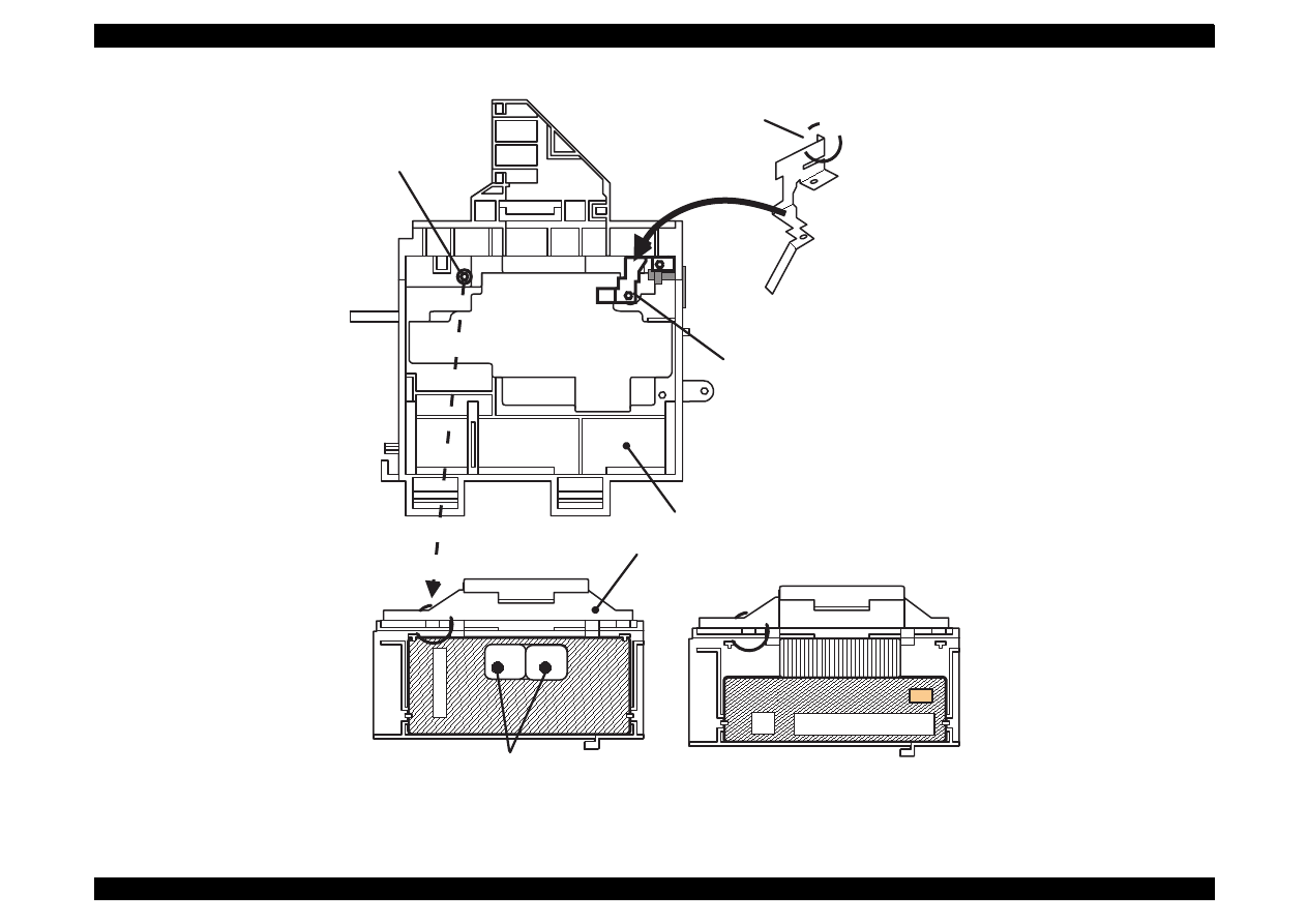
EPSON Stylus Color 440/640/740
Revision A
Chapter 4
Disassembly and Assembly
111
Figure 4-7. Installing the Printhead
Print Head
Carriage Assembly
Make sure that the protrusion
of the carriage is aligned with
the hole of the earth board.
This part should
be touching the
CR shaft receiver.
Make sure that this
protrusion is in the
U ditch of the priht head
side.
Nozzle Selector;
Stylus Color 440: 1 piece
Stylus Color 640: 2 pieces
Nozzle Selector has been enclosed into head.
Stylus Color 740
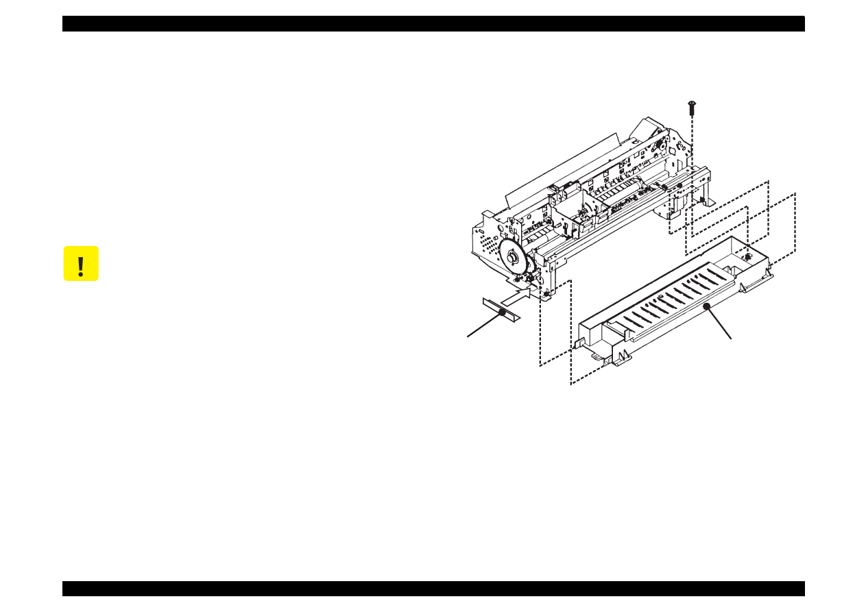
EPSON Stylus Color 440/640/740
Revision A
Chapter 4
Disassembly and Assembly
112
4.2.4.2 Removing the Absorber Tray Assembly ;A
1. Remove the housing. (Refer to Section 4.2.1.)
2. Remove the operation panel. (Refer to Section 4.2.3.)
3. Remove one screw (No.4) securing “Absorber tray assembly”
located on the right side of the printer mechanism.
4. On the right side of the printer mechanism, release the hook
securing the “Absorber tray assembly ;A” to the frame and remove
it, pulling it downward.
Figure 4-8. Removing the Absorber Tray Assembly ;A
C A U T I O N
When installing the absorber tray assembly ;A, make
sure to fix it with the spacer tray in the left side of the
printer mechanism.
S p a c e r T r a y
( N o . 4 )
A b s o r b e r T r a y A s s e m b l y ; A
EPSON Stylus Color 440/640/740
Revision A
Chapter 4
Disassembly and Assembly
113
4.2.4.3 Removing the Pump Assembly and Cap Assembly
1. Remove the housing. (Refer to Section 4.2.1.)
2. Remove the operation panel. (Refer toSection 4.2.3.)
3. Remove the absorber tray assembly ;A. (Refer to Section 4.2.4.2.)
4. Loosen two screws located on the edge of the paper eject frame
assembly and float release the joints for the paper eject assembly
and the side frames.
5. Raise the printer mechanism toward ASF side so that you can see
the bottom of the printer mechanism.
6. On the right side of frame, remove the hook holding the cap
assembly and release two protrusions attached to the frame, lifting
up the right side of cap assembly, then take it out towards the
bottom of the printer mechanism. Note that the cap assembly is still
connected to the pump assembly by the ink tube at this point. (Refer
to figures on the next page.)
7. Remove two screws (No.5) securing the pump assembly to the
frame. (Refer to the figures on the next page.)
8. Release a hook securing the pump assembly to the frame and
remove the pump assembly, moving it toward the right. (Refer to
figures on the next page.)
See the following pages for the figures below:
Figure 4-9, “Removing the Cap and Pump Assemblies”
Figure 4-10, “Component of Pump Assembly”
C A U T I O N
Do not damage the rubber part (black square) of the
cap installed in the cap assembly. (If it gets damaged,
it will not be able to adhere closely to the surface of
the print head, and may cause a malfunction in
operation.
When you replacing the cleaner head built in the
pump assembly, be careful of the following points.
Do not touch the cleaner head with your bare hands.
Use gloves or tweezers.
Do not let oil or grease touch the head cleaner.
When installing the cleaner head, set the rubber side
(black side) toward the right side of the frame.
When installing the pump assembly, do not tighten
the screw more than necessary torque.
C H E C K
P O I N T
Since the spring is included among the gears in the
pump assembly, be careful that the parts do not pop
out during disassembly and assembly.
When assembling the printer, be careful not to crush
nor leave any stress on the ink tube connecting the
pump assembly and the cap assembly.
After installing the pump assembly, make sure that the
cleaner parts move back and forth by rotating the gear
67.2.
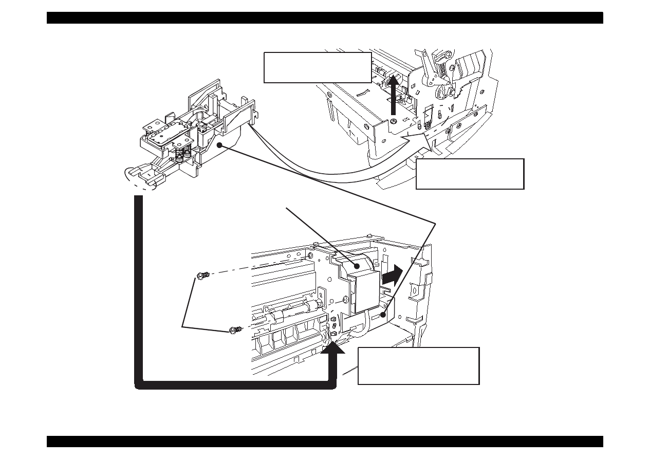
EPSON Stylus Color 440/640/740
Revision A
Chapter 4
Disassembly and Assembly
114
Figure 4-9. Removing the Cap and Pump Assemblies
Loosen screws on the right
and left sides and float the
Paper eject frame assembly.
Release three hooks
from the interior of the
right frame assembly.
Pump Assembly
Cap Assembly
Release a hook from the back
of the printer mechanism and
remove two protrusions from
the subframe.
(No.5)
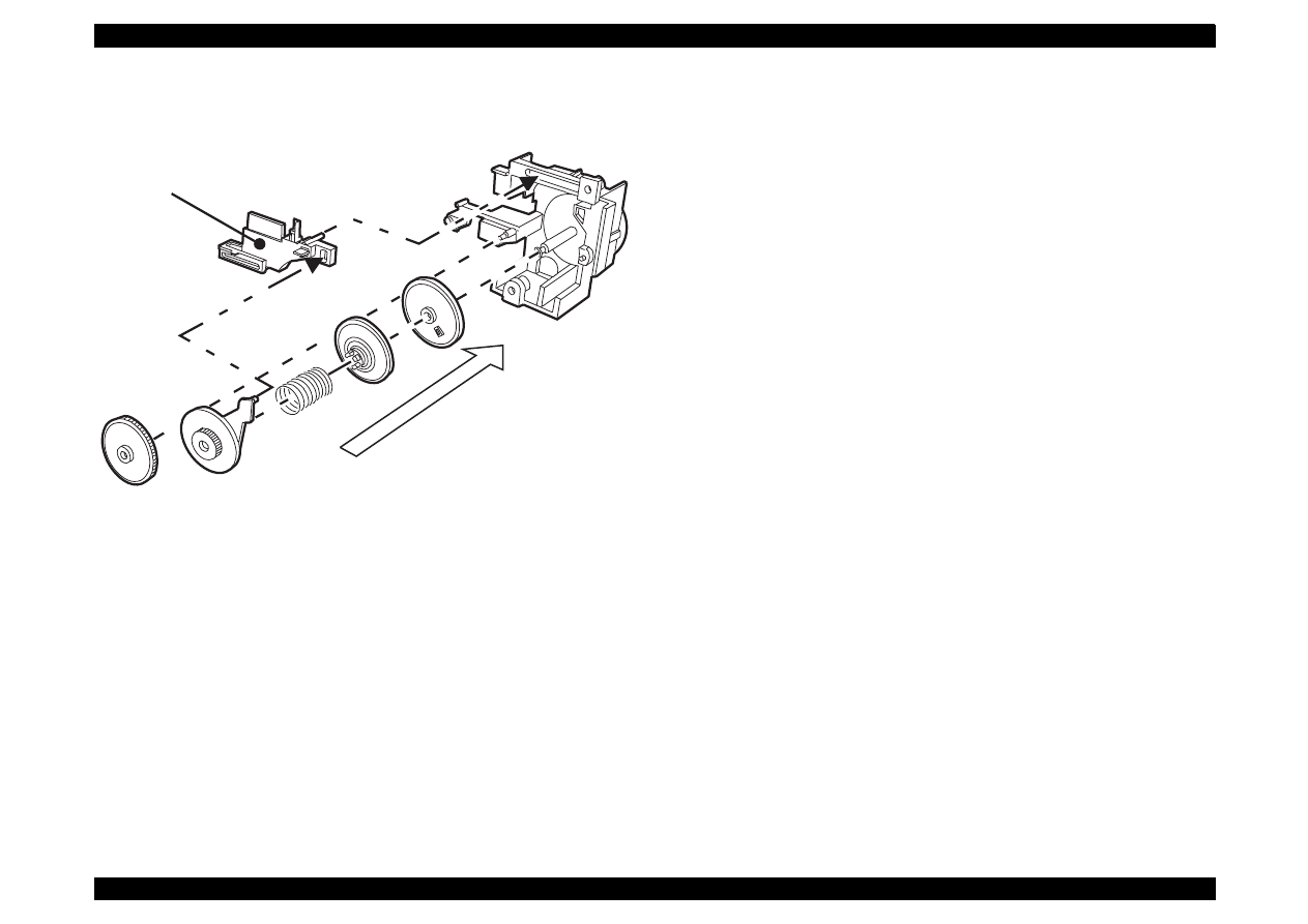
EPSON Stylus Color 440/640/740
Revision A
Chapter 4
Disassembly and Assembly
115
Figure 4-10. Component of Pump Assembly
Head Cleaner
Order of assembling
the pump parts.
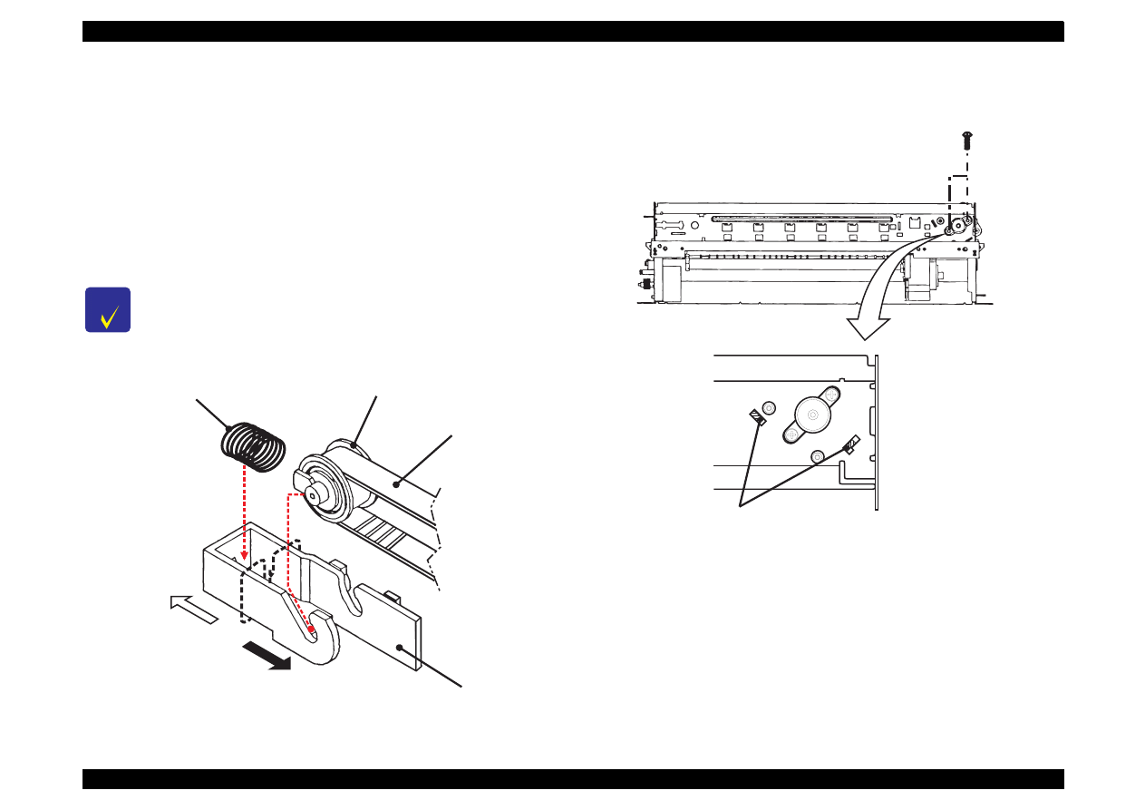
EPSON Stylus Color 440/640/740
Revision A
Chapter 4
Disassembly and Assembly
116
4.2.4.4 Removing the CR Motor Assembly
1. Remove the housing. (Refer to Section 4.2.1)
2. Rotate the gear 67.2 toward you and release the carriage lock
mechanism, then move the carriage to the center.
3. Loosen the timing belt by pushing the driven pulley holder and
remove the timing belt from the pulley on the CR motor.
4. Remove two screws(No.1) and remove the CR motor assembly.
Figure 4-11. Removing the Timing Belt
Figure 4-12. Removing and Installing the CR Motor Assembly
C H E C K
P O I N T
After installing the CR motor assembly, make sure that
two protrusions on the motor bracket are aligned with
the location holes in the frame. (Refer to Figure 4-12.)
D r i v e n P u l l e y A s s e m b l y
T i m i n g B e l t
D r i v e n P u l l e y H o l d e r
C o m p r e s s i o n S p r i n g 1 9 . 6
T o t h e I n t e r i o r o f S i d e F r a m e
T o t h e E x t e r i o r o f
S i d e F r a m e
( N o . 1 )
M a k e s u r e t h a t p r o t r u s i o n s o f C R f r a m e a r e i n t h e h o l e s
o f t h e f r a m e w h e n i n s t a l l i n g t h e C R m o t o r a s s e m b l y .
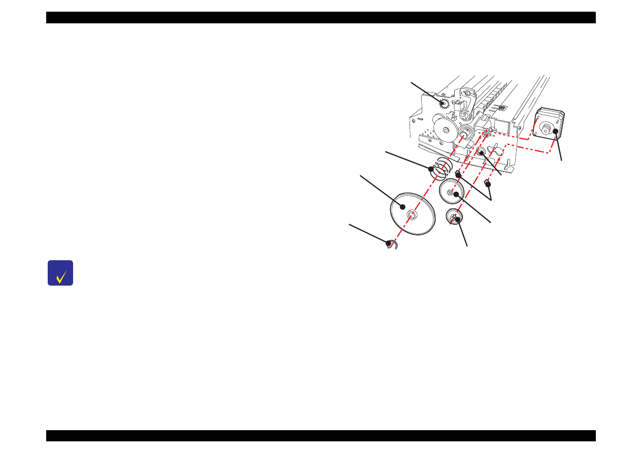
EPSON Stylus Color 440/640/740
Revision A
Chapter 4
Disassembly and Assembly
117
4.2.4.5 Removing the PF Motor Assembly
[For Stylus Color 740]
1. Remove the housing.(Refer to Section 4.2.1.)
2. Remove the absorber tray assembly ;A. (Refer to Section 4.2.4.2.)
3. Remove the following gears located on the left side of the printer
mechanism.
Gear 67.2 (Remove the ring with tweezers or a (-) driver. After
the ring is removed, if you try to remove the gear 67.2 by holding
its edge, the gear may break. So, try to remove it while holding
the whole gear, slightly pulling it toward you.)
Combination gear 8.8,21.6
Combination gear 8,14.4
Gear 36
4. Remove 2 hexagon nuts and remove the PF motor assembly.
Figure 4-13.
Removing the PF Motor Assembly for Stylus Color 740
C H E C K
P O I N T
When disassembling the PF motor assembly, pull the
motor assembly out of the frame a little bit and remove
it, sliding it into a larger hole in the frame. (See Figure
4-13.)
Be careful of the direction of the wires from the PF
motor assembly.
Do not damage or mar the grooves in the gears during
the disassembly and assembly.
C - R i n g
P R M o t o r A s s e m b l y
H e x a g o n N u t
C o m p r e s s i o n S p r i n g 0 . 9
G e a r 6 7 . 2
C o m b i n a t i o n S p r i n g 8 . 8 , 2 1 . 6
G e a r 3 6
C o m b i n a t i o n G e a r 8 , 1 4 . 4
G e a r 3 4
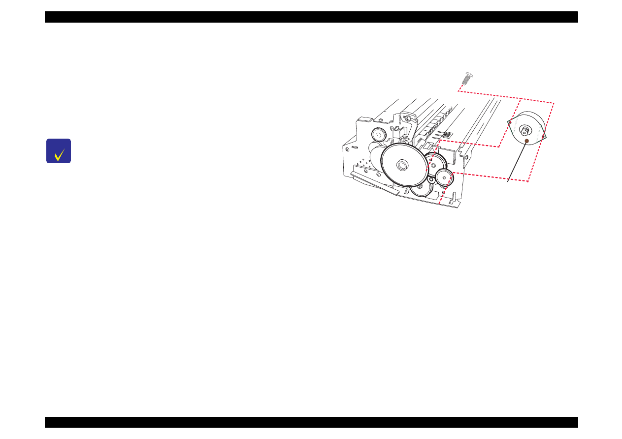
EPSON Stylus Color 440/640/740
Revision A
Chapter 4
Disassembly and Assembly
118
[For Stylus Color 440, 640]
1. Remove the housing. (Refer to Section 4.2.1.)
2. Remove the absorber tray assembly ;A. (Refer to Section 4.2.4.2.)
3. Remove the 2 screws securing the PF motor assembly. to the
frame.
Figure 4-14. Removing the PF Motor Assembly
(Stylus Color 440, 640)
C H E C K
P O I N T
When disassembling the PF motor assembly, pull the
motor assembly out of the frame a little bit and
remove it, sliding it into a larger hole in the frame.
(Refer to Figure 4-14.)
Be careful of the direction of the wires from the PF
motor assembly.
Do not damage or mar the grooves in the gears
during the disassembly and assembly.
P F M o t o r A s s e m b l y
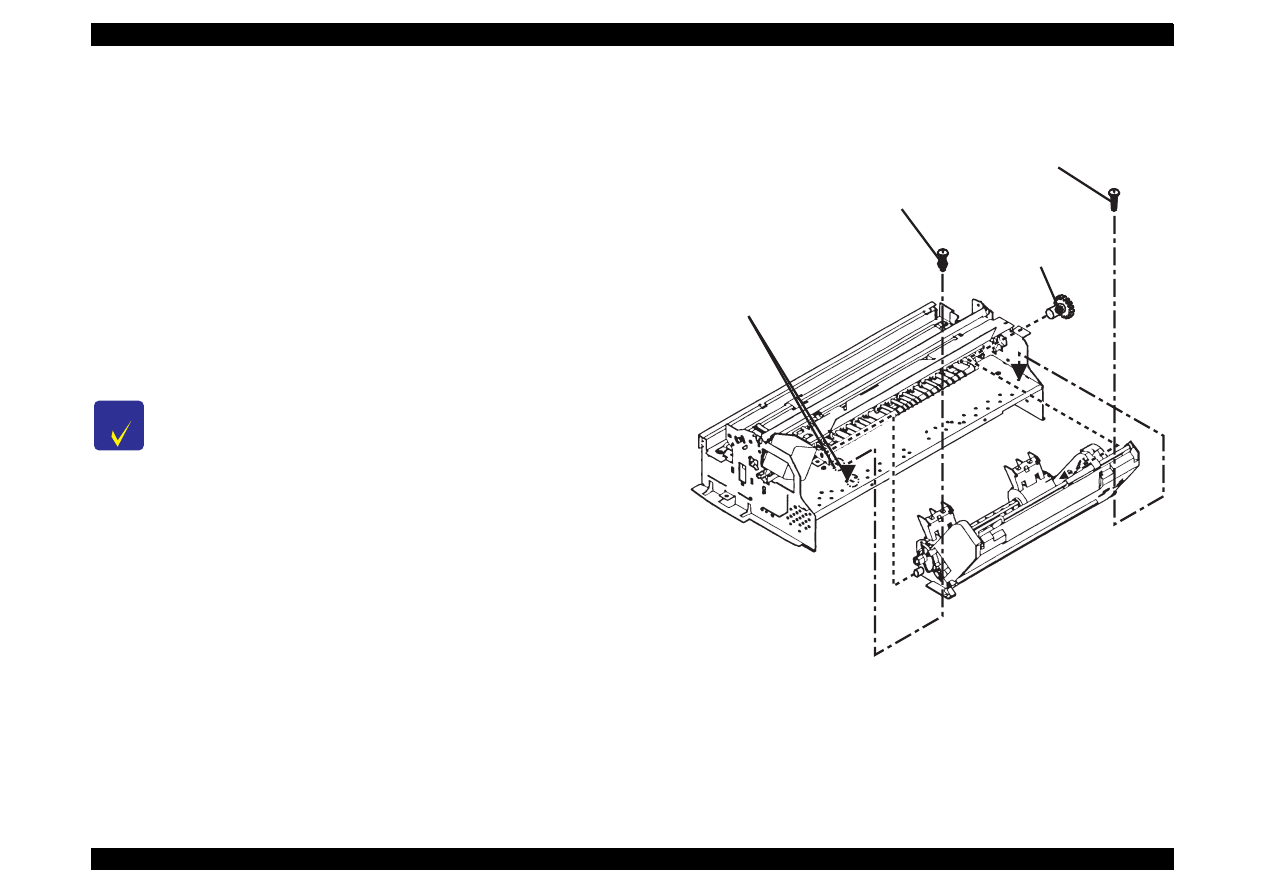
EPSON Stylus Color 440/640/740
Revision A
Chapter 4
Disassembly and Assembly
119
4.2.4.6 Removing the ASF Assembly
1. Remove the housing. (Refer to Section 4.2.1.)
2. Release the fixed hook from the inside of the printer mechanism and
remove the gear 34 from the roller shaft in the ASF assembly.
3. Remove the cables from the cable hook on the printer mechanism
and the hook on the ASF assembly.
4. After removing 2 screws (one No.7 screw and one CR shaft
installation screw), remove the ASF assembly, releasing the
protrusion on the left side of the ASF assembly from the hole in the
frame.
Figure 4-15. Removing the ASF Assembly
C H E C K
P O I N T
When installing the ASF assembly, make sure that the
frame and ASF assembly are attached each other
without any space between them.
Screws for ASF assembly should be used at the
following positions. (Looking from the back of
printer)
- Right:CR shaft installation screw
- Left:Screw No.7 (+Bind, S- tight, Sems R2; with a
plain washer)
S c r e w w i t h a W a s h e r ( N o . 7 )
G e a r 3 4
C R S h a f t I n s t a l l a t i o n S c r e w
M a k e s u r e t h a t t h e p r o t r u s i o n s i n t h e
A S F A s s e m b l y a r e i n t h e s e h o l e s
o n t h e f r a m e w h e n i n s t a l l i n g t h e
A S F a s s e m b l y .

EPSON Stylus Color 440/640/740
Revision A
Chapter 4
Disassembly and Assembly
120
4.2.4.6.1 Removing the Paper Feed Roller Assembly
1. Remove the ASF assembly. (Refer to Section 4.2.4.6.)
2. Remove the brake lever, releasing one leg of the torsion spring 41.2
from the hook of the ASF frame.
3. Remove the fixing shaft bushing from the right side of the LD roller
shaft and the release hopper lever.
4. Move the left paper feed assembly to the center and remove the
cam fixing bushing (white plastic) attached to the left side of LD
roller shaft.
5. Push the LD roller shaft to the left and remove the left shaft fixing
bushing after releasing its hook.
6. Remove the right and left sides of the hopper assembly from the
protrusions on the ASF frame.
7. Lift up the right side of paper feed roller assembly a little, move the
LD roller shaft to the right and remove it from the left side of the ASF
frame.
8. Holding the hopper assembly by hand, remove the cam part of
hopper assembly from the right holes of ASF frame.
The steps by here should remove the right and left LD roller assemblies
and the hopper assembly.
See the following page for Figure 4-16, “Disassembly of ASF
Assembly”.
C H E C K
P O I N T
During disassembly and assembly of the hopper
assembly, do not let the grease on the cam parts
touch other parts. Wipe off any grease smeared on
other parts.
Be careful of the direction of the hopper lever release
when installing it.
Make sure that the right and left fixing bushings are
installed steadily and do not slip off.
During assembly, attach the cam fixing bushing after
installing the LD roller shaft to the ASF frame.
When installing the right and left paper feed roller
assemblies to the LD roller shaft, the black paper feed
roller assembly goes on the right side and the one in
the standard EPSON color goes on the left of the
shaft.
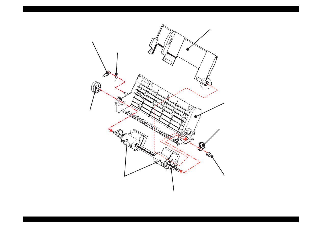
EPSON Stylus Color 440/640/740
Revision A
Chapter 4
Disassembly and Assembly
121
Figure 4-16. Disassembly of ASF Assembly
H o p p e r A s s e m b l y
A S F F r a m e
R e l e a s e H o p p e r L e v e r
P a p e r F e e d R o l l e r A s s e m b l y
L e f t S h a f t F i x i n g B u s h i n g
T o r s i o n S p r i n g 4 1 . 2
B r a k e L e v e r
L D R o l l e r S h a f t
( B l a c k )
( E P S O N s t a n d a r d c o l o r )
S h a f t F i x i n g B u s h i n g
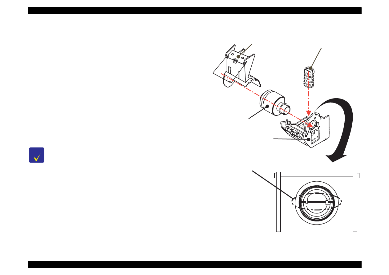
EPSON Stylus Color 440/640/740
Revision A
Chapter 4
Disassembly and Assembly
122
4.2.4.6.2 Removing the Right and Left LD Roller Assembly
1. Disassemble the ASF assembly and remove the paper feed roller
assembly and hopper assembly from the ASF assembly. (Refer to
Section 4.2.4.6.)
2. Take out the right and left compression springs 1.66 from the back
of the hopper assembly.
3. Pull out the cam part of the hopper assembly from the hole located
on the frame of the right LD roller assembly,
4. Pull out the LD roller shaft. The paper feed roller assembly and
hopper assembly should be disconnected by now.
5. Release the hook of LD roller assembly at the shaft hole of the
paper feed roller assembly. Also, release the fixed hook of the cover
roller LD and remove the LD roller assembly.
Figure 4-17. Disassembly of Paper Feed Roller Assembly
C H E C K
P O I N T
When installing the LD roller assembly, make sure
that the hooks are hung on the paper feed assembly.
During assembly, when setting the compression
spring 1.66 to the spring installation position in the
paper feed assembly, hang the spring on the hook
temporarily. Also, do not forget to release the hooks
of these springs from the holes located on the back of
paper feed assembly by rotating the spring. (Refer to
the figure below.)
C o m p r e s s i o n S p r i n g 1 . 6 6
L D R o l l e r A s s e m b l y
( R i g h t a n d L e f t )
P a p e r F e e d A s s e m b l y
( R i g h t a n d L e f t )
L D R o l l e r C o v e r
( R i g h t a n d L e f t )
+
P a p e r F e e d H o l d e r S h e e t
D u r i n g a s s e m b l y , s e t t h e c o m p r e s s i o n s p r i n g 1 . 6 6 i n
t h e p o s i t i o n f o r s p r i n g i n s t a l l a t i o n o f t h e p a p e r f e e d
a s s e m b l y a n d h a n g t h e b e n t p a r t o f t h e s p r i n g o n t h e h o o k .
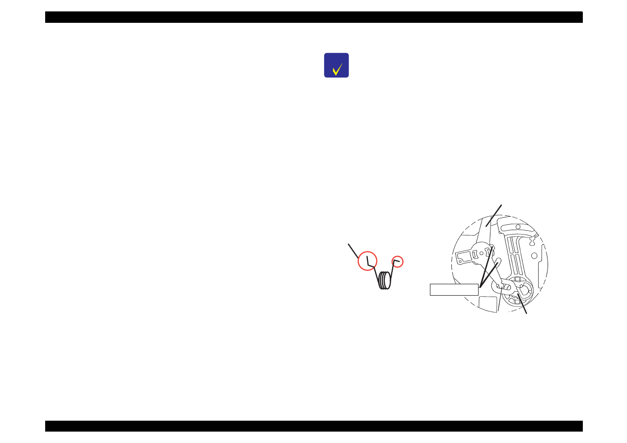
EPSON Stylus Color 440/640/740
Revision A
Chapter 4
Disassembly and Assembly
123
4.2.4.7 Removing the Carriage Assembly
1. Remove the housing. (Refer to Section 4.2.1)
2. Loosen the timing belt by pushing the driven pulley holder and
remove the timing belt from the pulley of the CR motor side.
3. Take the compression spring 19.6 out of the driven pulley holder.
4. Remove the driven pulley assembly from the driven pulley holder
with the timing belt. Slide the driven pulley holder and remove it from
the frame.
5. Remove the torsion spring hanging on the frame and PG lever.
Release the fixed hook of the PG lever and remove the lever.
6. Release the fixed hook of the PG lever support and remove the PG
lever support and washer from the edge of the CR guide shaft.
(Refer to the figure next page.)
7. Remove one screw(No.7) and rotate the right parallelism
adjustment bushing so that it fits in the notch of the frame, and
remove it.
8. Remove CR assembly with the CR guide shaft.
Figure 4-18. Installing the PG Lever
C H E C K
P O I N T
When disassembling the right parallelism adjustment
bushing, mark present location where the bushing is
fixed on the frame so that you can omit gap
adjustment after assembly.
When installing the washer, pay attention to its
direction.(Convex side should face the right
parallelism adjustment bushing side.) Refer to the
figure below.
When installing the PG lever, refer to the figure
below.
P G L e v e r
P G S u p p o r t L e v e r
E l l i p t i c H o l e s
T o t h e P G
L e v e r
I n s e r t t h i s s i d e t o t h e
h o l e o n t h e r i g h t f r a m e .
T o r s i o n S p r i n g 6 3 . 7
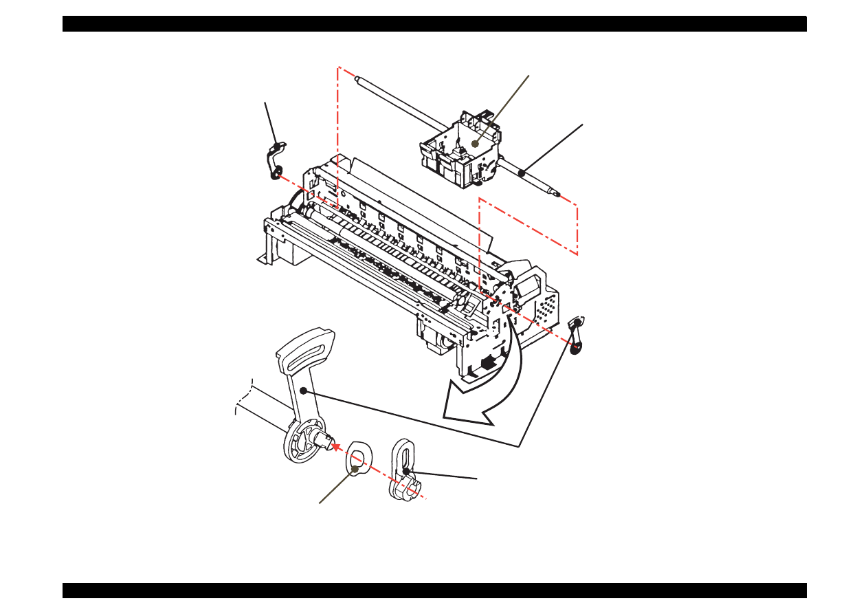
EPSON Stylus Color 440/640/740
Revision A
Chapter 4
Disassembly and Assembly
124
Figure 4-19. Removing the Carriage Assembly
P G S u p p o r t L e v e r
R i g h t P a r a l l e l i s m A d j u s t m e n t B u s h i n g
W a s h e r
[ C o n v e x s i d e s h o u l d f a c e t o t h e b u s h i n g s i d e d u r i n g i n s t a l l a t i o n ]
L e f t P a r a l l e l i s m
A d j u s t m e n t B u s h i n g
C R G u i d e S h a f t
C a r r i a g e A s s e m b l y
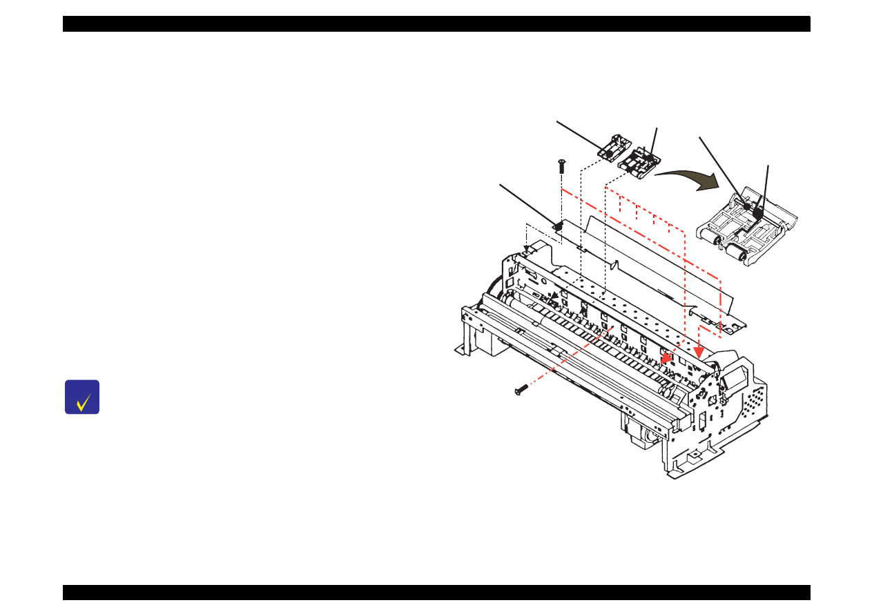
EPSON Stylus Color 440/640/740
Revision A
Chapter 4
Disassembly and Assembly
125
4.2.4.8 Removing the PF Roller Assembly
1. Remove the housing.(Refer to Section 4.2.1.)
2. Remove the carriage assembly.(Refer to Section 4.2.4.7.)
3. Remove three screws(No.1) on the printer mechanism and
disassemble the cable guide board.
4. Remove six upper paper guide assemblies, releasing their springs
from the hooks in the frame.
5. Remove the front paper guide ;B, releasing the hooks. (Refer to
next page.)
6. Remove the paper eject roller assembly, releasing the fixed locks
located on the right and left edges of the shaft.
7. Release the fixed hook located on the left side of the PF roller
assembly shaft and rotate it so that the protrusion on the shaft
(white) and hole for receiving the shaft in the frame align.
8. Slide the PF roller assembly to the right and pull it out.
Figure 4-20. Removing the Paper Guide Assembly
C H E C K
P O I N T
During disassembly and assembly of the upper paper
guide assemblies, since one of the upper paper guide
assemblies to be installed on the right side overlaps
with the PE detector lever, pay attention not to damage
the lever.
Be careful not to damage the hook during disassembly
and assembly of the front paper guide ;B.
Be careful not to scratch the PF roller assembly during
disassembly and assembly, since its surface is
specially coated to improve paper feeding. (black part)
Be careful not to damage the combination gears.
C a b l e G u i d e B o a r d
( N o . 1 )
U p p e r P a p e r G u i d e
A s s e m b l y
L e f t P a p e r G u i d e
T o r s i o n S p r i n g
1 1 7 . 6
U p p e r P a p e r G u i d e S h a f t
( 6 p o s i t i o n s )
( N o . 1 )
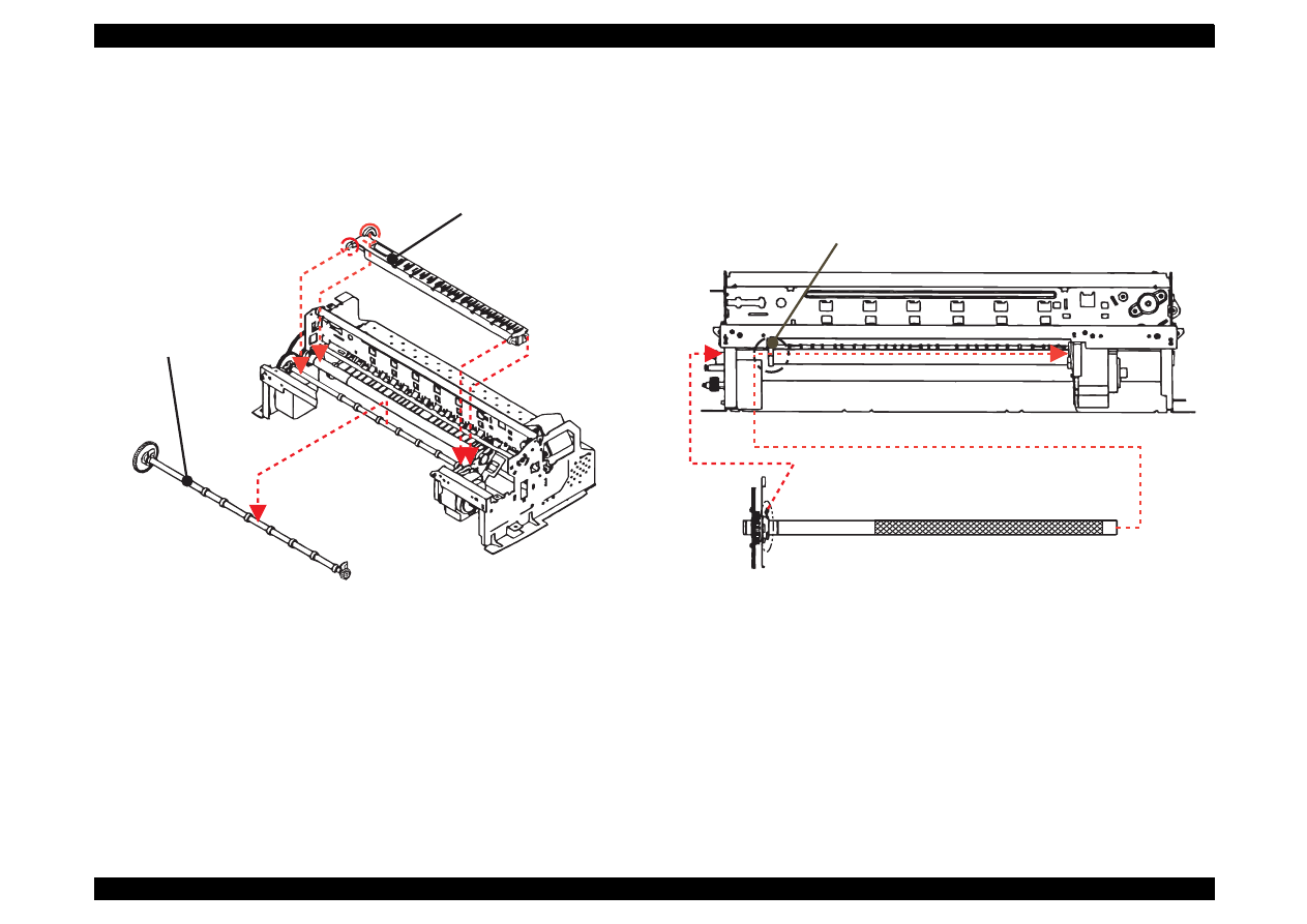
EPSON Stylus Color 440/640/740
Revision A
Chapter 4
Disassembly and Assembly
126
Figure 4-21. Removing the Paper Eject Roller Assembly
Figure 4-22. Removing the PF Roller Assembly
F r o n t P a p e r G u i d e ; B
E j e c t P a p e r R o l l e r
A s s e m b l y
P F R o l l e r A s s e m b l y
A l i g n t h e p r o t r u s i o n i n t h e P F r o l l e r
a s s e m b l y w i t h t h e h o l e i n t h e f r a m e f o r
h o l d i n g t h e s h a f t .
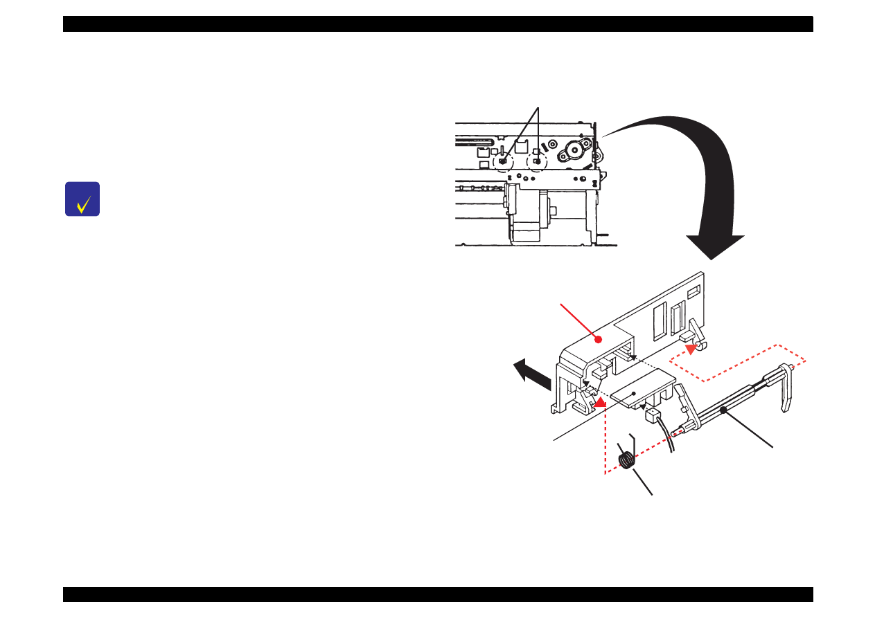
EPSON Stylus Color 440/640/740
Revision A
Chapter 4
Disassembly and Assembly
127
4.2.4.9 Removing the PE Paper Detector Assembly
1. Remove the housing. (Refer to Section 4.2.1.)
2. Release two fixed hooks securing the PE detector assembly from
the back of the frame and remove the PE detector assembly, sliding
it upward. Remove the PE board assembly and PE lever, if
necessary.
Figure 4-23. Removing the PE Detector Assembly
C H E C K
P O I N T
During assembly, make sure that the tip (sensor part) of the
detector lever is in the hole of paper guide assembly.
A f t e r r e l e a s i n g t w o h o o k s , r e m o v e
t h e P E p a p e r d e t e c t o r a s s e m b l y ,
s l i d i n g i t u p w a r d .
P E L e v e r
T o r s i o n S p r i n g 0 . 2 2
P E B o a r d A s s e m b l y
P E H o l d e r
T h i s s i d e s h o u l d b e
i n s t a l l e d o n t h e f r a m e .
( F r o m b a c k s i d e o f t h e f r a m e )

EPSON Stylus Color 440/640/740
Revision A
Chapter 4
Disassembly and Assembly
128
4.2.4.10 Removing the HP Detector
1. Remove the housing. (Refer to Section 4.2.1.)
2. Remove the cable from the HP detector and take it out after
releasing the fixed hook.
Figure 4-24. Removing the HP Detector
H P D e t e c t o r

ADJUSTMENT
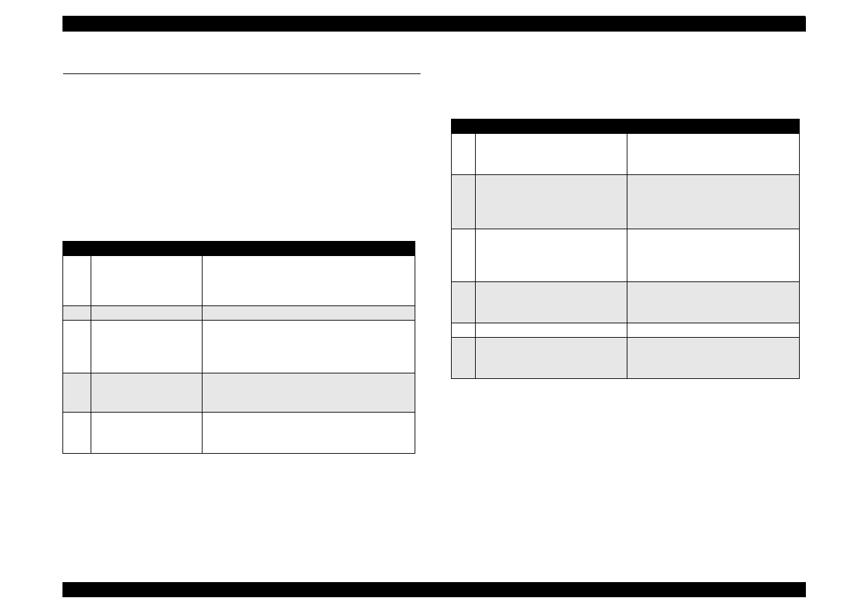
EPSON Stylus Color 440/640/740
Revision A
Chapter 5
Adjustment
130
5.1 Overview
This chapter describes adjustments required when the printer is
disassembled and assembled after repair.
5.1.1 Required Adjustments
Stylus Color 440/640/740 require the following adjustments. (Refer to
Table 5-1) Perform any necessary adjustment referring to the figures
and procedures described throughout this chapter.
Table below shows the actions taken and required adjustments in the
order to be performed.
Table 5-1 Adjustment Required
No.
Adjustment Item
Conditions
1
Parallelism Adjustment
• When you replace or remove the Carriage
guide shaft.
• When you move the parallelism adjustment
bushing.
2
Initial Ink Charge
• When you replace or remove the printhead.
3
Head Voltage ID Input
• When you replace the printhead.
• When you replace the main board.
Note) The values stored in this address are not
erased by EEPROM reset operation.
4
Printing Head Angle
Adjustment
• When you replace or remove the printhead.
• When you move the printhead angle adjusting
lever.
5
Bi-D Adjustment
• When you replace or remove the printhead.
• When you replace the main board.
• When you replace the CR Motor.
Table 5-2 Actions Taken and Adjustment Required
No.
Content of Operation
Adjustment Procedure
1
Removal of the printhead
1. Perform initial ink charge.
2. Perform printhead angle adjustment.
3. Perform Bi-d Adjustment.
2
Replacement of the printhead
1. Perform Vh voltage writing operation.
2. Perform initial ink charge.
3. Perform printhead angle adjustment.
4. Perform Bi-d Adjustment.
3
Replacement of the main board
1. Perform Vh voltage writing operation.
2. Perform Bi-d adjustment.
3. Perform CG TAble setting (only for
Stylus Color 740)
4
Replacement or Removal of the
Carriage Unit
1. Perform parallel adjustment.
2. Perform printhead angle adjustment.
3. Perform Bi-d adjustment.
5
Replace of the CR Motor
1. Perform Bi-d adjustment.
6
Replacement of the Printer
Mechanism
1. Perform Head Voltage ID Input.
2. Perform initial ink charge.
3. Perform Bi-d adjustment.
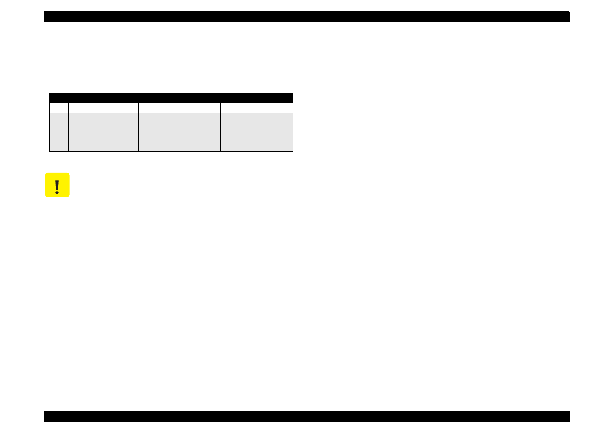
EPSON Stylus Color 440/640/740
Revision A
Chapter 5
Adjustment
131
5.1.2 Adjustment Tools Required
Table 5-3 below shows adjustment tools for Stylus Color 440/640/740.
Table 5-3 Adjustment Tools Required
No.
Name
Adjustment Item
Contents/Spec.
1
Thickness Gauge
Parallelism Adjustment
1.04 mm
2
Adjustment Program
Each Mechanism Settings
Exclusive Program;
SC440.EXE
SC640.EXE
SC740.EXE
C A U T I O N
N e ve r u s e th e b e n t (cu rve d o r tilte d ) o r ru s ty th ick n e s s
g a u g e .
E ra s e a n y d irt, g re a se o r o b sta cle s o n th e th ic kn e ss g a u g e
b e fo re y o u u se it.
EPSON Stylus Color 440/640/740
Revision A
Chapter 5
Adjustment
132
5.2 Adjustment
This section explains specific procedures for each adjustment required
for Stylus Color 440/640/740.
5.2.1 Parallelism Adjustment
When replacing the carriage assembly or removing it during printer
mechanism disassembly, perform the parallelism adjustment during
assembling and set the standard distance from the surface of the
printhead to the paper surface.
[Right Parallelism Adjustment]
1. Install the "parallelism adjustment bushing” for right and left frame
and set them on the peaking of the upper frame side so that they
match with “the standard mark of parallelism adjustment bushing".
2. Set the PG lever front. (Gap is small.)
3. Move the carriage to the center and set the thickness gauge on the
fixed position of front paper guide ;B as you can see in the figure 4-1
on the next page
4. Move the carriage to the position that the printhead overlaps the
thickness gauge.
5. Move the right parallelism adjustment bushing to the rear until the
thickness gauge moves with the carriage when you move the
carriage about 20 mm right and left. (Gap will be narrowed.)
6. From this thickness with which the thickness gauge starts moving
with the carriage, move the gear of the right parallelism adjustment
bushing one notch toward you. (Gap will be widen.
7. With the PG lever set front (gap is small) and then rear, move the
carriage right and left and make sure that the thickness gauge does
not move for the both settings.
[Left Parallelism Adjustment]
8. Perform Steps 2 to 7 for the left parallelism adjustment bushing.
[Checking parallelism]
9. Perform steps 1 to 4 again.
10. Make sure that the thickness gauge does not move right and left
along with the carriage when the carriage is moved about 20 mm.
11. Move the right parallelism adjustment bushing one notch to the rear
(Gap will be narrowed).Then check that the thickness gauge moves
along with the carriage. If the thickness gauge does not move, go
back to Step 1 and repeat the adjustment.
12. If the gap is adjusted correctly, move the right parallelism
adjustment bushing one notch toward you (Gap will be widen).
C A U T I O N
Do not scratch the special coated surface of the PF roller
assembly and rib surface of the front paper guide ;B.
Be careful not to leave any mar or dirt on the surface of the
printhead. (Never use a rusty or dirty thickness gauge. Also, do
not push the thickness gauge hard against the head.)
C H E C K
P O I N T
Put the thickness gauge on the flat side of the
rib of the front paper guide ;B.
When you move the carriage, move it, pulling
the timing belt with your hand.
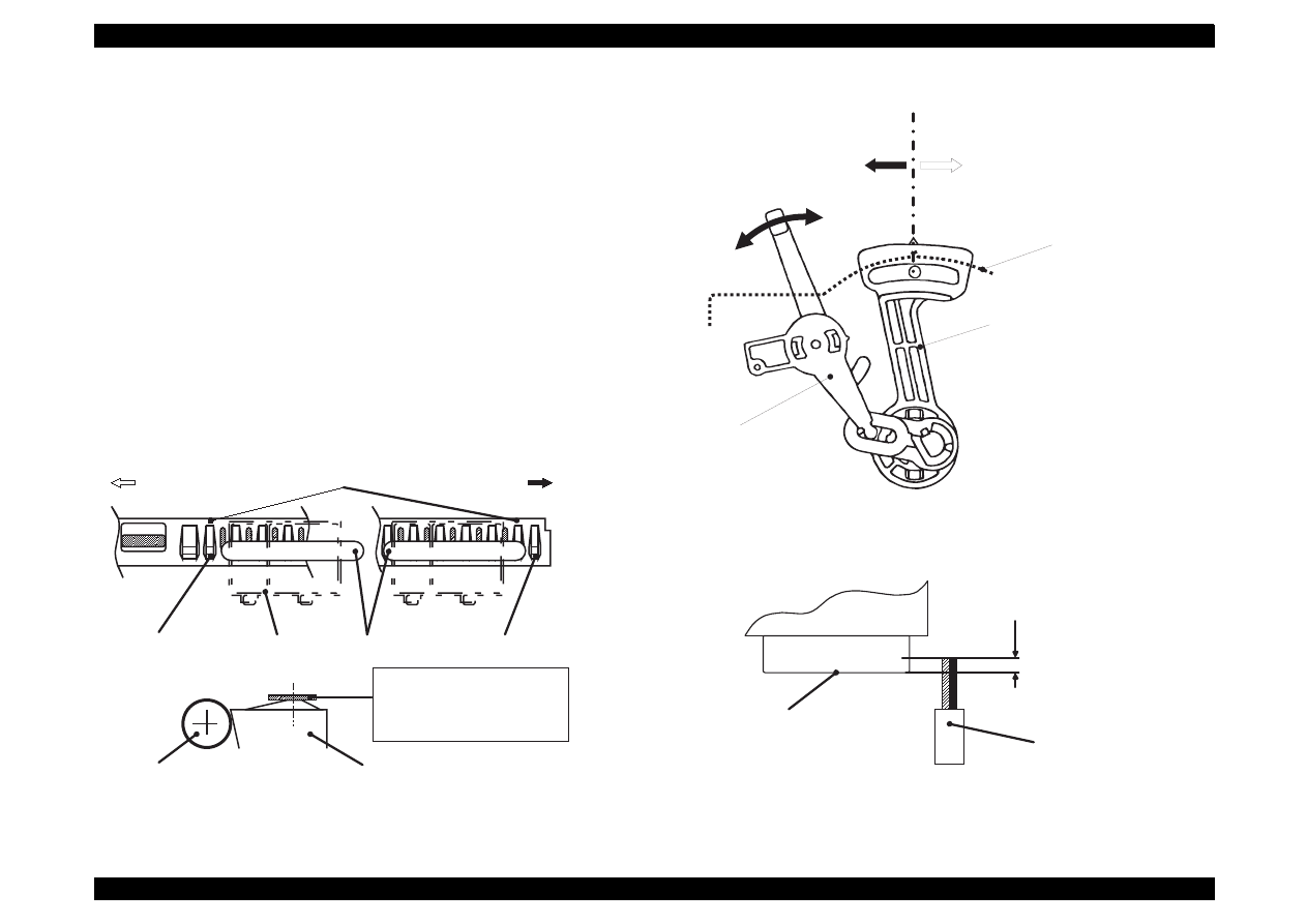
EPSON Stylus Color 440/640/740
Revision A
Chapter 5
Adjustment
133
[Fixing Parallelism Adjustment Bushing]
13. Fix the right and left parallelism adjustment bushings with screws.
(No.1 screw for each.)
When completing this adjustment, check the overlap amount of the
printhead and head cleaner.
1. Rotate the gear 67.2 and move the head cleaner to the printer rear
side.
2. Move the carriage next to the head cleaner and make sure that
overlap between the tip of the printhead and cleaner head is more
than 0.5 mm.
3. Then, rotate the gear 67.2 and return the head cleaner to the front
position.
Figure 5-1. Setting of the Gauge at Parallelism Adjustment
Figure 5-2. Parallelism Adjustment
Figure 5-3. Overlap of Head Surface and Cleaner Blade
Left
"PAPER GUIDE, FRONT;B"
Right
(HP side)
Rib: Avoid 2ribs from left
Carriage
Assembly
[Thickness Gauge] Rib: Avoid 1 rib at right end
"ROLLER, ASSEMBLY, PF"
"PAPER GUIDE, FRONT;B"
*Put the gauge on a flat face
*Align the center of gauge and
the ribs
P o s i t i o n M a r k
F o r w a r d
( G a p : W
i d e r )
B a c k w a r d
( G a p : N a r r o w e r )
S i d e F r a m e
" B U S H , P A R A L L E L A D J U S T , R I G H T "
" L E V E R , P G "
( 0 )
( + )
Printhead
(Nose face)
"CLEANER, HEAD"
Overlap = 0.5mm or more
CR
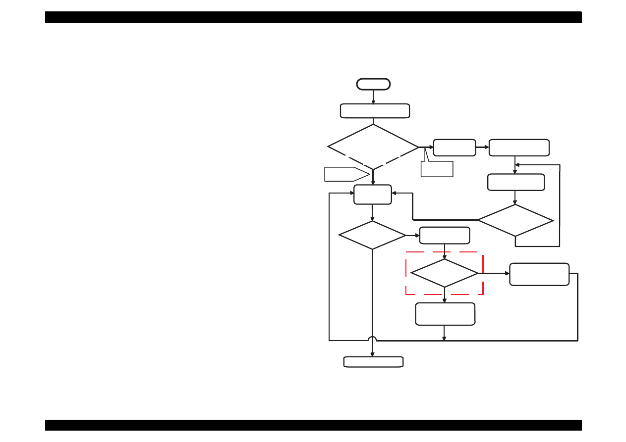
EPSON Stylus Color 440/640/740
Revision A
Chapter 5
Adjustment
134
5.2.2 Adjustment by Adjustment Program
In this printer, it is necessary to set the correct information for each
printer mechanism in order to maintain consistent printing function and
quality, eliminating difference of each printer mechanism
'
s
characteristics.
Therefore, in case that the combination of the printer mechanism and
main board changes or the printhead is replaced during repair, you
must set and save the correct information to the main board, using the
exclusive adjustment program.
5.2.2.1 About Adjustment Program
The adjustment program (Program name:SC440.EXE, SC640.EXE,
SC740.EXE) enables you to set various values correctly to prevent
malfunction and fluctuation of printing quality and printing function
caused by difference in components and assembly when the printer
components are replaced during repair. Basic adjustment procedure by
using this program are shown in the right column.
The flowchart below shows the steps to follow before entering the main
menu.
Figure 5-4. Interface Flow of Adjustment Program
Model Name confirmation
by using Nibble-mode.
Start
"Not
registored."
"Is the model
name correct?"
Type "E" while
pressing the Alt key.
You must type the
model name correctly.
The model
name has been
typed correctly?
Message:
"Not registered"
Yes
Message:
"Is the model
name correct?"
No
to Retype mode
Select "Yes" or "No".
Yes
No
Destination and CG
table change mode
NLSP or Standard?
Standard
NLSP
Setting the Destination
to World and CG table
to the Standard ver.
Setting the Destination
to World and CG table
to the NLSP ver.
To the Main menu
Which is the
message on the screen,
"Model name is not registored ."
*: This prompt is only available for
Stylus Color 640 and 740. However,
Stylus Color 640 has no CG on the
C256 Main board, so that you can
not print out the NLSP characters.
or "Is the model name
correct?"
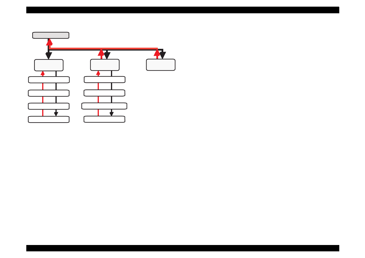
EPSON Stylus Color 440/640/740
Revision A
Chapter 5
Adjustment
135
Figure 5-5. Options in the Program and Keys to Use
Main menu
Maintenance
Adjustment
Market/Destination Check
Head Voltage ID Input
Head Angular Adjustment
Bi-D Adjustment
Head Cleaning(CL2)
Ink Charge Flag Reset
Transportation Liquid Charge
Protection Counter value
A4 Check
Pattern
ESC Key
Return Key
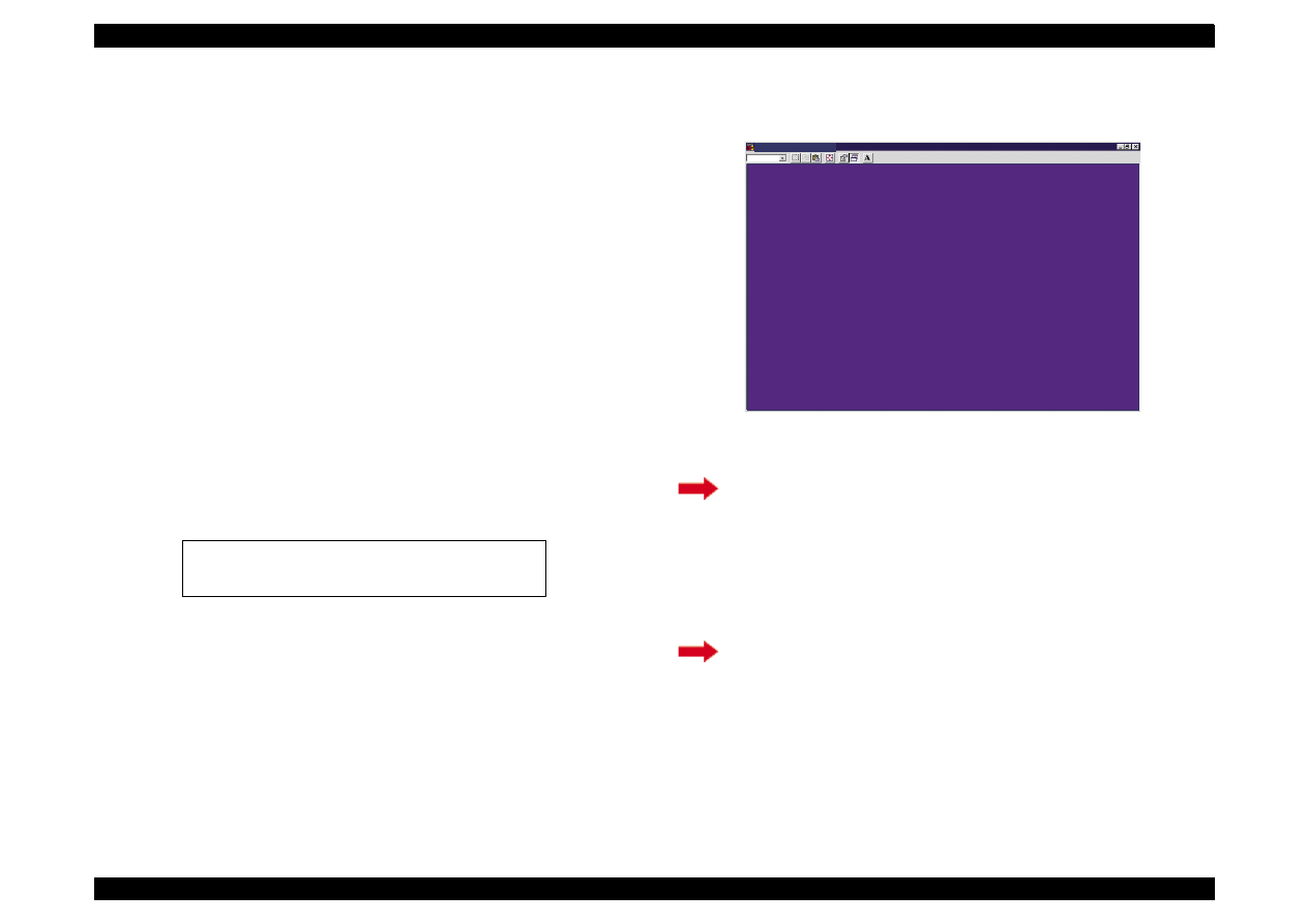
EPSON Stylus Color 440/640/740
Revision A
Chapter 5
Adjustment
136
5.2.2.2 Entering the Main menu
Before performing any adjustment, you need to enter the main menu,
however, you may have to take the following extra steps before entering
the main menu depending on the printer model name and mode name
registration status.
Registering the model name (Section 5.2.2.2.1.)
Setting the CG (Section 5.2.2.2.2.)
Therefore, read the instructions carefully and take the appropriate
steps.
1. Connect the printer and PC and turn on the printer.
2. Insert the disk for the adjustment program to the floppy disk drive.
Type SC440, SC640, or SC740 on the DOS or DOS prompt.
3. Type the exclusive program name* SC440.EXE, SC640.EXE, or
SC740.EXE on the DOS prompt.
* The adjustment program name provided with each printer is shown
below.
4. Following screen appears.
Figure 5-6. Initial Screen (1)
A(In case of FD):\SC440.EXE for Stylus Color 440
A(In case of FD):\SC640.EXE for Stylus Color 640
A(In case of FD):\SC740.EXE for Stylus Color 740
If the printer’s model name has been registered, go to
[For Stylus Color 740]
If your printer is Stylus Color 740, you must set the
correct CG,
NLSP
or
Standard
. Therefore, be sure to
read the instructions in the following step carefully to
take the proper steps.
If no model name is registered, go to
M S - D O S P r o m p t - S C 6 4 0
A u t o
S t a r t i n g t h e s e r v i c e p r o g r a m .
C h e c k i n g t h e m o d e l n a m e n o w .
N o t e :
T h i s s c r e e n i s c o m m o n f o r S t y l u s C o l o r 4 4 0 , 6 4 0 ,
a n d 7 4 0 e x c e p t f o r t h e p r o g r a m n a m e .

EPSON Stylus Color 440/640/740
Revision A
Chapter 5
Adjustment
137
5. After a few seconds, the model name appears on the screen shown
below. Proceed to one of the following steps.
Figure 5-7. Initial Screen (2)
6. The main menu shown below appears.
Figure 5-8. Main Menu of the Program
If the printer is Stylus Color 440 or 640, go to
Step 6
.
If the printer is Stylus Color 740, go to
C A U T I O N
If the screen above does not appear, it means no model
name is registered, and you must proceed to
Section
5.2.2.2.1 / Step 1
as the screen automatically advances
to the Mode Name Null Condition screen (Figure 5-9).
M S - D O S P r o m p t - S C 6 4 0
A u t o
I s t h e m o d e l n a m e c o r r e c t ?
N o ( S e l e c t t o c h a n g e t h e C G
o r m a r k e t i n f o r m a t i o n . )
Y e s
E S C : P r e v i o u s U p / D o w n a r r o w s : S e l e c t E N T E R : O K
N o t e :
T h i s s c r e e n i s c o m m o n f o r S t y l u s C o l o r 4 4 0 , 6 4 0 ,
a n d 7 4 0 e x c e p t f o r t h e p r o g r a m n a m e .
M S - D O S P r o m p t - S C 6 4 0
A u t o
* * * * * * E P S O N S t y l u s C O L O R 6 4 0 S E R V I C E P R O G R A M V e r s i o n 1 . 0 * * * * * *
< > < > S E R V I C E I T E M S < > < >
< < M a i n t e n a n c e > >
< < P r i n t A 4 P a t t e r n > >
< < A d j u s t m e n t > >
N o t e :
T h i s s c r e e n i s c o m m o n f o r S t y l u s C o l o r 4 4 0 , 6 4 0 ,
a n d 7 4 0 e x c e p t f o r t h e p r o g r a m n a m e .
E s c : Q u i t U p / D o w n a r r o w s : S e l e c t E n t e r : O K
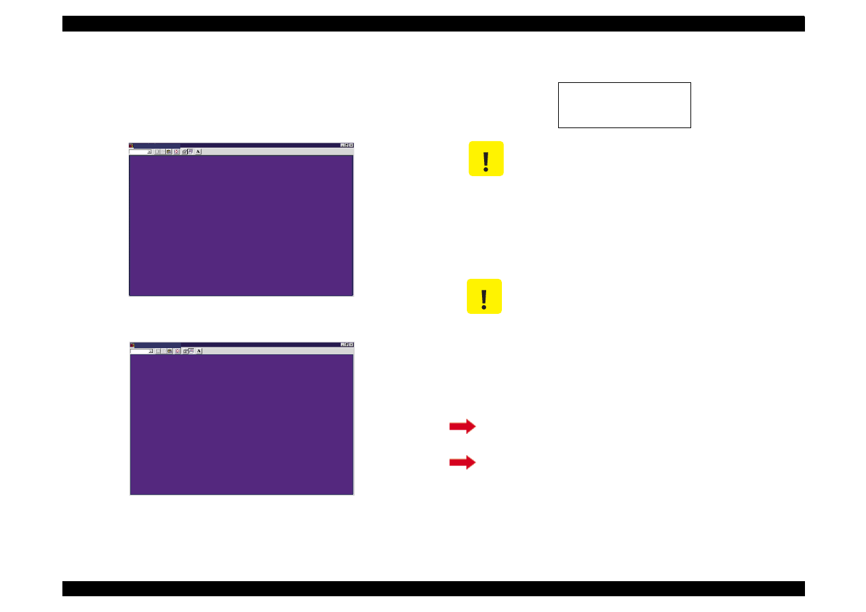
EPSON Stylus Color 440/640/740
Revision A
Chapter 5
Adjustment
138
5.2.2.2.1 Registering the printer model name
1. If no model name is registered, the screen shown below appears. Press
the E key while pressing the Alt key, and the program advances to
the Model Name Input Screen.
Figure 5-9. Model Name Null Condition
Figure 5-10. Model Name Input Screen
2. Type the correct model name, referring to the box below.
3.
After a few seconds, the model name appears on the Initial Screen
(2) (Figure 5-7). Proceed to one of the following steps.
M S - D O S P r o m p t - S C 6 4 0
A u t o
S t a r t i n g S E R V I C E P R O G R A M
P r i n t e r m o d e l n a m e i s n o t r e g i s t e r e d .
N o t e :
T h i s s c r e e n i s c o m m o n f o r S t y l u s C o l o r 4 4 0 , 6 4 0 ,
a n d 7 4 0 e x c e p t f o r t h e p r o g r a m n a m e .
M S - D O S P r o m p t - S C 6 4 0
A u t o
P l e a s e t y p e t h e p r i n t e r m o d e l n a m e ,
a n d t h e n p r e s s t h e E n t e r k e y .
> >
_
N o t e :
T h i s s c r e e n i s c o m m o n f o r S t y l u s C o l o r 4 4 0 , 6 4 0 ,
a n d 7 4 0 e x c e p t f o r t h e p r o g r a m n a m e .
Stylus
_
COLOR
_
440
Stylus
_
COLOR
_
640
Stylus
_
COLOR
_
740
C A U T I O N
"
-
"means a space.
Be sure to type the model name in exactly the
same way as shown above, paying attention
to the text formats, uppercase or lowercase.
If you mistype the model name, the program
will automatically return to the model name
input screen (Figure 5-10).
C A U T I O N
For Stylus Color 740:
If the printer is Stylus Color 740, you must set
the correct CG,
NLSP
or
Standard.
Therefore, be
sure to read the instructions below carefully to
take the proper steps.
If the printer is Stylus Color 440/640, return to
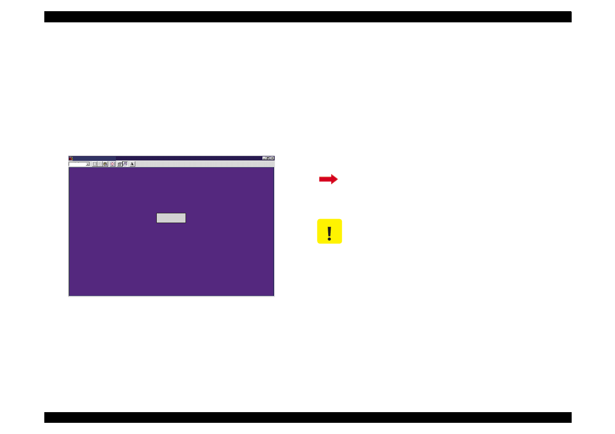
EPSON Stylus Color 440/640/740
Revision A
Chapter 5
Adjustment
139
5.2.2.2.2 Setting the CG (Destination information)
(For Stylus
Color 740 only)
Since there are two models for Stylus Color 740, the standard model
and NLSP model, you are required to set the correct CG according to
the model by following the steps described in this section.
1.
(For Stylus Color 740 only)
Select
"No"
on the Initial Screen (2) (Figure 5-7), and the screen
below appears.
Figure 5-11. Destination Setting Screen for Stylus Color 740
2.
(For Stylus Color 740 only)
Perform one of the followings:
If your Stylus Color 740 supports the NLSP characters, select
NLSP by using the reverse carols. Be sure to perform this
operation because a spare C257 Main board has the CG set to
Standard at factory.
If your Stylus Color 740 does not support the NLSP characters,
select Standard.
The program automatically returns to the Initial Screen (2) (Figure 5-7)
after a few seconds
.
M S - D O S P r o m p t - S C 7 4 0
A u t o
S e l e c t t h e d e s t i n a t i o n .
S t a n d a r d
N L S P
N o t e :
T h i s s c r e e n i s c o m m o n f o r S t y l u s C o l o r 4 4 0 , 6 4 0 ,
a n d 7 4 0 e x c e p t f o r t h e p r o g r a m n a m e .
E s c : P r e v i o u s U p / D o w n a r r o w s : S e l e c t E n t e r : O K
The CG value has been correctly set. Return to
C A U T I O N
Do not select the NLSP if your Stylus Color 740 does
not support the NLSP characters. You can distinguish
the NLSP model from Standard model by referring to
the following point on the C257 Main board;
Standard: There is no IC6 on C257 Main board.
NLSP: There is IC6 on C257 Main board.

EPSON Stylus Color 440/640/740
Revision A
Chapter 5
Adjustment
140
5.2.2.3 Initial Ink Charge Operation
There is no ink charged in the ink path of a spare printhead and printer
mechanism. Therefore, after you replaced any of the following units,
perform initial ink charge and return the printer after making sure that
ink is ejected correctly from the printhead.
After replacing the printer mechanism
After replacing or removing the printhead
1. Enter the main menu. (Refer to Section 5.2.2.2.)
2. In the main menu (Figure 5-7), select Maintenance using the Up/
Down arrow key, and the Maintenance Menu below appears.
Figure 5-12. Maintenance Menu of the Program
3. By using the Up/Down arrow key, select Ink Charge Flag Reset in
the maintenance menu (Figure 5-12), and the Initial Ink Charge
Menu below appears.
Figure 5-13. Initial Ink Charge Menu
4. Press the Enter key while the reverse cursor is indicating Yes.
5. Turn off the printer and back on after 10 seconds, and the printer
automatically enters the initial ink charge sequence.
(It takes 90 seconds for this operation to complete the whole
sequence.)
M S - D O S P r o m p t - S C 6 4 0
A u t o
* * * * * * E P S O N S t y l u s C O L O R 6 4 0 S E R V I C E P R O G R A M V e r s i o n 1 . 0 * * * * * *
< M A I N T E N A N C E >
I n k c h a r g e f l a g r e s e t
T r a n s p o r t a t i o n L i q u i d C h a r g e
I n d i c a t i o n o f t h e c o u n t e r v a l u e f o r t h e w a s t e i n k p a d
H e a d c l e a n i n g
N o t e :
T h i s s c r e e n i s c o m m o n f o r S t y l u s C o l o r 4 4 0 , 6 4 0 ,
a n d 7 4 0 e x c e p t f o r t h e p r o g r a m n a m e .
E s c : Q u i t U p / D o w n a r r o w s : S e l e c t E n t e r : O K
C A U T I O N
Before you set the initial ink charge flag, replace the
installed cartridges with new ones, because the ink
amount used for the initial ink charge operation is so
large.
M S - D O S P r o m p t - S C 6 4 0
A u t o
D o y o u w a n t t o r e s e t t h e i n i t i a l i n k c h a r g e f l a g ?
Y e s
N o
- - N o t e t h e i n k a m o u n t c o n s u m e d f o r t h i s o p e r a t i o n . - -
( 1 / 7 o f B l a c k a n d 1 / 1 1 o f Y M C o f e x i s t i n g i n k i s c o n s u m e d e a c h t i m e . )
* * P e r f o r m t h i s o p e r a t i o n a f t e r i n s t a l l i n g b o t h n e w i n k c a r t r i d g e s . * *
I n i t i a l I n k C h a r g e - - -
P e r f o r m i n g t h e i n i t i a l i n k c h r g e .
[ T o t a l q u a n t i t y o f b l a c k i n k a b s o r p t i o n = 2 . 2 9 m l ]
[ T o t a l q u a n t i t y o f c o l o r i n k a b s o r p t i o n = 3 . 4 5 m l ]
E s c : Q u i t U p / D o w n a r r o w s : S e l e c t E n t e r : O K
N o t e :
T h e i n f o r m a t i o n p r o v i d e d i n t h i s t o o l i s c o m m o n f o r t h e E P S O N S t y l u s
C O L O R 4 4 0 , 6 4 0 , a n d 7 4 0 p r i n t e r s e x c e p t f o r p r i n t e r s p e c i f i c i n f o r m a t i o n
s u c h a s i n k a b s o r p t i o n q u a n t i t y .

EPSON Stylus Color 440/640/740
Revision A
Chapter 5
Adjustment
141
5.2.2.4 Head Cleaning Operation
Different from the previous models, Stylus Color 440, 640, and 740
have no dummy cleaning sequence called CL3, which was performed to
prevent ink from being unnecessarily consumed when cleaning was
repeated without any printout. However, Stylus Color 440/640/740 is
alternatively equipped with the strongest cleaning sequence CL2
contained in this adjustment program. With this sequence, you can
forcibly solve the clogged nozzle problem caused by viscous ink.
1. Enter the main menu. (Refer to Section 5.2.2.2.)
2. Apply the Maintenance menu (Figure 5-12).
3. By using the Up/Down arrow key, select Head cleaning, and the
following screen appears.
Figure 5-14. Cleaning Menu
4. Press the Enter key. The printer enters the CL2 sequence.
(It takes
60 seconds for the process to complete.)
C A U T I O N
If you can not recover the clogged nozzles despite you
performed CL2 operation, enter the Initial ink charge
sequence by referring to Section 5.2.2.3.
M S - D O S P r o m p t - S C 6 4 0
A u t o
M o d e s e l e c t i o n o f h e a d c l e a n i n g
B l a c k & C o l o r h e a d c l e a n i n g
< < P o w e r f u l c l e a n i n g ( C L 2 ) w i l l b e d o n e i n t h i s m o d e . > >
N o t e :
T h i s s c r e e n i s c o m m o n f o r S t y l u s C o l o r 4 4 0 , 6 4 0 ,
a n d 7 4 0 e x c e p t f o r t h e p r o g r a m n a m e .
E s c : Q u i t U p / D o w n a r r o w s : S e l e c t E n t e r : O K

EPSON Stylus Color 440/640/740
Revision A
Chapter 5
Adjustment
142
5.2.2.5 Protection Counter Indicate/Reset
The program provided with this manual can let you confirm or clear the
current protection counter value.
(Of course, you can confirm or clear
the current protection value by main unit alone. Refer to table 1-21 and
1-22 for details.)
[Confirming the current protection counter value]
1. Enter the main menu. (Refer to Section 5.2.2.2.)
2. Apply the maintenance menu (Figure 5-12).
3. By using the Up/Down arrow key, select Indication of the counter
value for the waste ink pad. The screen below appears.
Figure 5-15. Current Protection Counter Conformation (1) Screen
4. Press the Enter key while the reverse cursor is indicating Check the
protect counter value. The screen below appears.
Figure 5-16. Current Protection Counter Conformation (2)
M S - D O S P r o m p t - S C 6 4 0
A u t o
P r o t e c t i o n C o u n t e r C H E C K / C L E A R
C h e c k t h e p r o t e c t c o u n t e r v a l u e
C l e a r t h e p r o t e c t c o u n t e r v a l u e
N o t e :
T h i s s c r e e n i s c o m m o n f o r S t y l u s C o l o r 4 4 0 , 6 4 0 ,
a n d 7 4 0 e x c e p t f o r t h e p r o g r a m n a m e .
E s c : Q u i t U p / D o w n a r r o w s : S e l e c t E n t e r : O K
M S - D O S P r o m p t - S C 6 4 0
A u t o
R e a d i n g o u t t h e p r e s e n t p r o t e c t c o u n t e r v a l u e
C o u n t e r V a l u e ( d e c ) = 3 1 3 p o i n t s
M a x i m u m i s 1 9 , 8 0 0 p o i n t s .
I f i t i s o v e r 9 , 8 0 0 p o i n t s , r e p l a c e t h e w a s t e i n k p a d .
N o t e :
T h i s s c r e e n i s c o m m o n f o r S t y l u s C o l o r 4 4 0 , 6 4 0 ,
a n d 7 4 0 e x c e p t f o r t h e p r o g r a m n a m e .
E s c : P r e v i o u s

EPSON Stylus Color 440/640/740
Revision A
Chapter 5
Adjustment
143
[Clearing the current protection counter value]
1. Enter the main menu. (Refer to Section 5.2.2.2 )
2. Apply the maintenance menu.
3. By using the Up/Down arrow key, select the item Indication of the
counter value for the waste ink pad in the maintenance menu
(Figure 5-12). The Current Protection Counter Conformation (1)
Screen shown in Figure 5-15 appears.
4. By using the Up/Down arrow key, select the Clear the protect
counter value on the screen. The screen shown below appears.
Figure 5-17. Current Protection Counter Clear Screen
5. Press the Enter key while the reverse cursor is indicating Already
replaced. The screen below appears.
Figure 5-18. Zero Clear of Protect Counter Value
M S - D O S P r o m p t - S C 6 4 0
A u t o
T h e w a s t e i n k p a d m u s t b e r e p l a c e d b e f o r e c l e a r i n g t h e c o u n t e r .
H a v e n o t r e p l a c e d
A l r e a d y r e p l a c e d
N o t e :
T h i s s c r e e n i s c o m m o n f o r S t y l u s C o l o r 4 4 0 , 6 4 0 ,
a n d 7 4 0 e x c e p t f o r t h e p r o g r a m n a m e .
E s c : P r e v i o u s U p / D o w n a r r o w s : S e l e c t E n t e r : O K
C A U T I O N
Be sure to replace the installed waste ink pad with a
new one after or before you clear the current
protection counter value.
If you select
Have not replaced
, the current screen
automatically returns to the previous screen (Figure
5-17).
M S - D O S P r o m p t - S C 6 4 0
A u t o
N o w c l e a r i n g t h e p r o t e c t c o u n t e r !
E s c : P r e v i o u s
< < T h e p r o t e c t c o u n t e r h a s b e e n r e s e t t o z e r o > >
C h e c k t h e c o u n t e r b y p r e s s i n g t h e E s c k e y t w i c e .
N o t e :
T h i s s c r e e n i s c o m m o n f o r S t y l u s C o l o r 4 4 0 , 6 4 0 ,
a n d 7 4 0 e x c e p t f o r t h e p r o g r a m n a m e .

EPSON Stylus Color 440/640/740
Revision A
Chapter 5
Adjustment
144
5.2.2.6 Market/Destination Check
(only for Stylus Color 740)
As already mentioned, there are two models for Stylus Color 740,
Standard model and NLSP model, and you are required to set the
suitable destination depending on the type of the main board supported.
Without this operation (Market/destination setting), users can not use
the NLSP characters despite their printers are equipped with the CG-
ROM(IC6) on the main board.
For this reason, always confirm the market/destination status on the
Destination Setting Screen for Stylus Color 740 (Figure 5-19) after
you change or set a CG.
1. Enter the main menu. (See Section 5.2.2.2 .)
2. Apply the adjustment menu. The following screen appears.
Figure 5-19. Adjustment Menu of the Program
3. By using the Up/Down arrow key, select Market Destination
Check. The following screen appears.
Figure 5-20. Market/Destination Checking Screen
C A U T I O N
Do not select
"
NLSP
"
unless your Stylus Color 740
supports the NLSP characters. You can distinguish
the NLSP model from the Standard one by checking
the following points on the C257 Main board:
*Standard: There is no IC6 on C257 Main board.
*NLSP: There is IC6 on C257 Main board.
On the other hand, if you set the destination to
"Standard" despite your Stylus Color 740 supports
NLSP characters, they will not be used.
Even though your spare C257 Main board is a NLSP
version, it has already been set as a standard version
in the EEPROM. Therefore, you have to set it as a
NLSP version in the EEPROM after installing a new
NLSP version board (with IC6 mounted).
M S - D O S P r o m p t - S C 6 4 0
A u t o
< < A d j u s t m e n t > >
H e a d V o l t a g e I D I n p u t
H e a d A n g u l a r A d j u s t m e n t ( P r i n t C h e c k P a t t e r n )
B i - D i r e c t i o n a l A d j u s t m e n t
M a r k e t D e s t i n a t i o n C h e c k
N o t e :
T h i s s c r e e n i s c o m m o n f o r S t y l u s C o l o r 4 4 0 , 6 4 0 ,
a n d 7 4 0 e x c e p t f o r t h e p r o g r a m n a m e .
E s c : Q u i t U p / D o w n a r r o w s : S e l e c t E n t e r : O K
* * * * * * E P S O N S t y l u s C O L O R 6 4 0 S E R V I C E P R O G R A M V e r s i o n 1 . 0 * * * * * *
M S - D O S P r o m p t - S C 6 4 0
A u t o
C h e c k i n g t h e M a r k e t D e s t i n a t i o n
C h e c k i n g a p r e s e n t M a r k e t D e s t i n a t i o n
N o t e :
T h i s s c r e e n i s c o m m o n f o r S t y l u s C o l o r 4 4 0 , 6 4 0 ,
a n d 7 4 0 e x c e p t f o r t h e p r o g r a m n a m e .
E s c : P r e v i o u s E n t e r : O K

EPSON Stylus Color 440/640/740
Revision A
Chapter 5
Adjustment
145
4. Press the Enter key, and the screen below appears. The terms
World and Standard show the current value set in the destination
and CG addresses in the EEPROM.
Figure 5-21. Market/Destination Confirmation Menu
5. You can return to the adjustment menu by pressing the Esc key
twice.
M S - D O S P r o m p t - S C 6 4 0
A u t o
R e a d i n g o u t a p r e s e n t M a r k e t D e s t i n a t i o n
M a r k e t d e s t i n a t i o n i s W
o r l d S t a n d a r d
E s c : P r e v i o u s
C u r r e n t D e s t i n a t i o n
C u r r e n t C G
N o t e :
T h i s s c r e e n i s c o m m o n f o r S t y l u s C o l o r 4 4 0 , 6 4 0 ,
a n d 7 4 0 e x c e p t f o r t h e p r o g r a m n a m e .
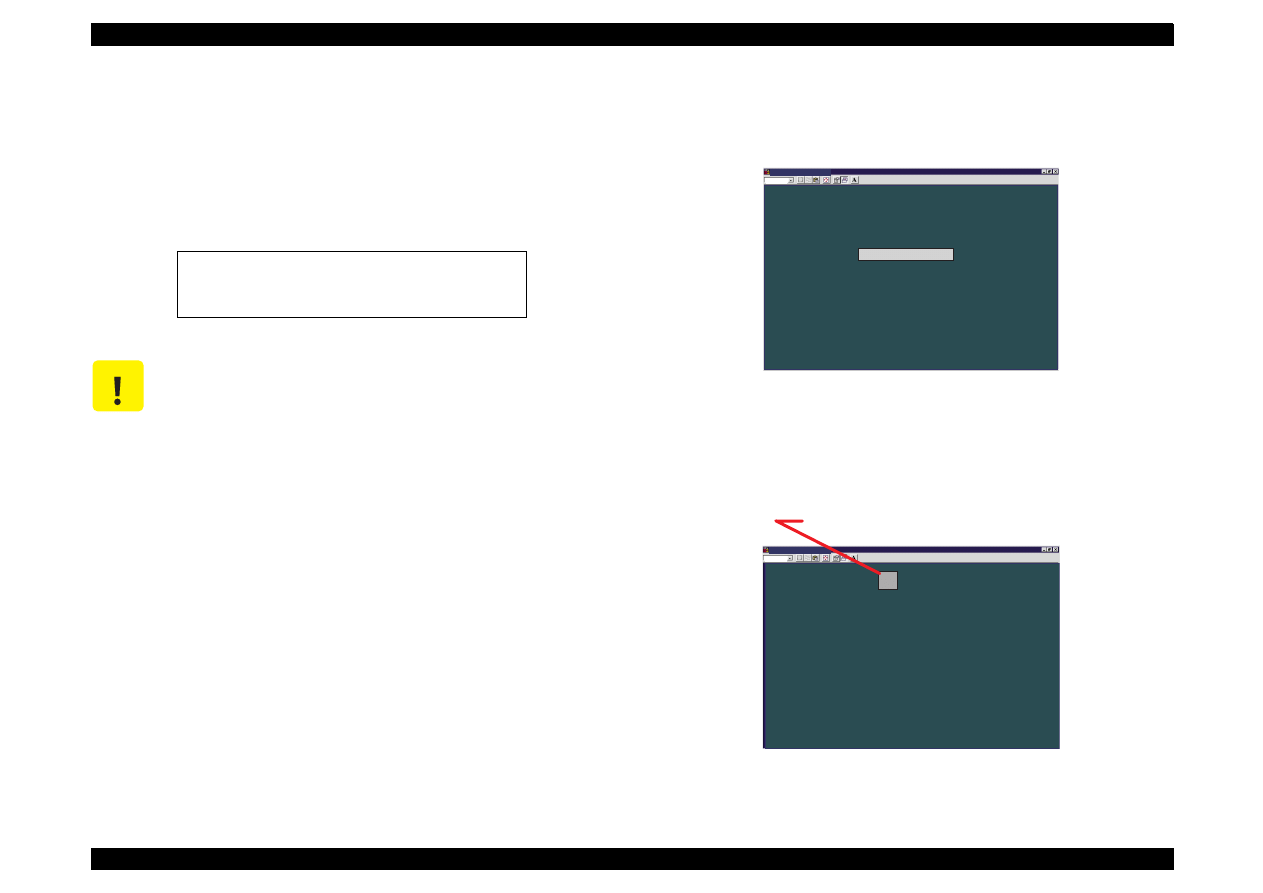
EPSON Stylus Color 440/640/740
Revision A
Chapter 5
Adjustment
146
5.2.2.7 Head Voltage ID Input
Head voltage value adjustment function enables you to write printhead
ID. This operation is considered the most important to maintain proper
ink discharging system. If an ID is not written correctly, it results in white
or color lines and also gives bad influence on dot weight. This
adjustment is required in the following cases.
1. When replacing any of the parts above, make a note of VH voltage
ID appointed in advance. You can find the VH voltage ID on the
following position:
Printhead:
On the side face of the printhead.
Printer mechanism:
On the label of the packing box of the
printer mechanism.
2. Apply the main menu (Figure 5-21). (See Section 5.2.2.2.)
3. By using the Up/Down arrow key, select Adjustment in the main
menu.
4. By using the Up/Down arrow key, select Head Voltage ID Input in
the adjustment menu. (Figure 5-19.)
The following screen appears.
Figure 5-22. Head Voltage ID Check/Input Select Menu
5. By using Up/Down arrow key, select Change data, and the
following screen appears.
Figure 5-23. Head Voltage ID Input Menu
1. When exchanging the main board
2. When exchanging the printhead
3. When exchanging the printer mechanism
C A U T I O N
Before or after performing this operation, refer to the
table 5-2 and perform any appropriate adjustments or
operations.
M S - D O S P r o m p t - S C 6 4 0
A u t o
H e a d v o l t a g e a d j u s t m e n t
C h a n g e d a t a
C h e c k p r e s e n t d a t a
N o t e :
T h i s s c r e e n i s c o m m o n f o r S t y l u s C o l o r 4 4 0 , 6 4 0 ,
a n d 7 4 0 e x c e p t f o r t h e p r o g r a m n a m e .
E s c : P r e v i o u s U p / D o w n a r r o w s : S e l e c t E n t e r : O K
M S - D O S P r o m p t - S C 6 4 0
A u t o
E n t e r t h e d i g i t v o l t a g e I D
H E A D A C T U A T O R V O L T A G E I D =
E n t e r : O K
5
F o r t h e S t y l u s C o l o r 4 4 0 , t h e I D i s
3
d i g i t s
F o r t h e S t y l u s C o l o r 6 4 0 , t h e I D i s
5
d i g i t s
F o r t h e S t y l u s C o l o r 7 4 0 , t h e I D i s
8
d i g i t s

EPSON Stylus Color 440/640/740
Revision A
Chapter 5
Adjustment
147
6. When you input the head ID value, the screen automatically
advances consequently, as shown below:
Figure 5-24. Head Voltage ID Writing Screen
7. Press the Esc key once. The screen returns to the Head Voltage ID
Check/Input Select Menu. (See Figure 5-22.)
8. By using the Up/Down arrow key, select Check present data on the
screen. The screen below appears.
Figure 5-25. Input ID Confirmation Menu
M S - D O S P r o m p t - S C 6 4 0
A u t o
W
r i t i n g t o E E P R O M n o w .
M S - D O S P r o m p t - S C 6 4 0
A u t o
E s c : P r e v i o u s
T h i s p r o c e s s t a k e s a b o u t
5 s e c o n d s .
N o t e :
T h e i n f o r m a t i o n p r o v i d e d i n t h i s s e r v i c e t o o l i s c o m m o n f o r t h e S t y l u s C o l o r 4 4 0 , 6 4 0 ,
a n d 7 4 0 e x c e p t f o r s o m e p r i n t e r s p e c i f i c i n f o r m a t i o n s u c h a s i n k c o u n t e r l i m i t s .
N o t e :
T h e i n f o r m a t i o n p r o v i d e d i n t h i s s e r v i c e t o o l i s c o m m o n f o r t h e S t y l u s C o l o r 4 4 0 , 6 4 0 ,
a n d 7 4 0 e x c e p t f o r s o m e p r i n t e r s p e c i f i c i n f o r m a t i o n s u c h a s i n k c o u n t e r l i m i t s .
1 8 2 1 8
h a s b e e n w r i t t e n i n E E P R O M a s t h e
H E A D A C T U A T O R V O L T A G E I D .
M S - D O S P r o m p t - S C 6 4 0
A u t o
R e a d i n g t h e p r e s e n t h e a d v o l t a g e v a l u e .
H E A D V O L T A G E I D = 1 8 2 1 8
E s c : P r e v i o u s
N o t e :
T h e i n f o r m a t i o n p r o v i d e d i n t h i s s e r v i c e t o o l i s c o m m o n f o r t h e S t y l u s C o l o r 4 4 0 , 6 4 0 ,
a n d 7 4 0 e x c e p t f o r s o m e p r i n t e r s p e c i f i c i n f o r m a t i o n s u c h a s i n k c o u n t e r l i m i t s .

EPSON Stylus Color 440/640/740
Revision A
Chapter 5
Adjustment
148
5.2.2.8 Head Angular Adjustment
During production, slight variations are created in printheads and
carriage (which are used as a printhead base.) If these differences are
not adjusted, they can adversely influence the printhead angle, and
color overlapping is not performed correctly and color/white line
problem occurs as a result. Therefore, in order to adjust the printhead
angle correctly, the exclusive lever for adjusting the printhead angle is
installed on the side of the carriage unit. By moving this lever, you are
able to adjust the printhead angle without removing the ink cartridge.
This adjustment is required in the following cases.
When a printhead is replaced.
When the carriage unit is replaced.
When the angle adjustment lever is moved.
Print the check pattern in the adjustment program to determine the
angle degree needed for the printhead. Then move the adjustment lever
in the carriage unit to set the printhead angle referring to the printed
check pattern.
1. Remove the upper case from the main unit. (Refer to Chapter 4.)
NOTE:
If you perform this adjustment with the upper case installed, select
“Move the carriage to the head angular adjustment position” on
Current Head Angular Confirmation Menu (1) screen (Figure 5-26)
before loosening the screw.
2. Apply the main menu (Figure 5-21). (See Section 5.2.2.2.)
3. By using the Up/Down arrow key, select Adjustment in the main
menu. By using the Up/Down arrow key, select Head Angular
Adjustment. The following screen appears.
Figure 5-26. Current Head Angular Confirmation Menu (1)
4. Select Head Angular Adjustment Pattern and press Enter key. The
screen below appears and the printer prints the head angular
adjustment pattern (Figure 5-28).
Figure 5-27. Current Head Angular Confirmation Menu (2)
C A U T I O N
Before or after performing this operation, refer to Table
5-2 and perform appropriate adjustments or
operations.
M S - D O S P r o m p t - S C 6 4 0
A u t o
H e a d A n g u l a r A d j u s t m e n t
E s c : P r e v i o u s
H e a d A n g u l a r A d j u s t m e n t p a t t e r n
E n t e r : O K
N o t e :
T h e i n f o r m a t i o n p r o v i d e d i n t h i s s e r v i c e t o o l i s c o m m o n f o r t h e S t y l u s C o l o r 4 4 0 , 6 4 0 ,
a n d 7 4 0 e x c e p t f o r s o m e p r i n t e r s p e c i f i c i n f o r m a t i o n s u c h a s i n k c o u n t e r l i m i t s .
M o v e t h e c a r r i a g e t o t h e h e a d a n g u l a r a d j u s t m e n t p o s i t i o n .
R e t u r n t h e c a r r i a g e t o t h e h o m e p o s i t i o n .
M S - D O S P r o m p t - S C 6 4 0
A u t o
T h e H e a d A n g u l a r A d j u s t m e n t p a t t e r n i s n o w p r i n t i n g .
N o t e :
T h e i n f o r m a t i o n p r o v i d e d i n t h i s s e r v i c e t o o l i s c o m m o n f o r t h e S t y l u s C o l o r 4 4 0 , 6 4 0 ,
a n d 7 4 0 e x c e p t f o r s o m e p r i n t e r s p e c i f i c i n f o r m a t i o n s u c h a s i n k c o u n t e r l i m i t s .
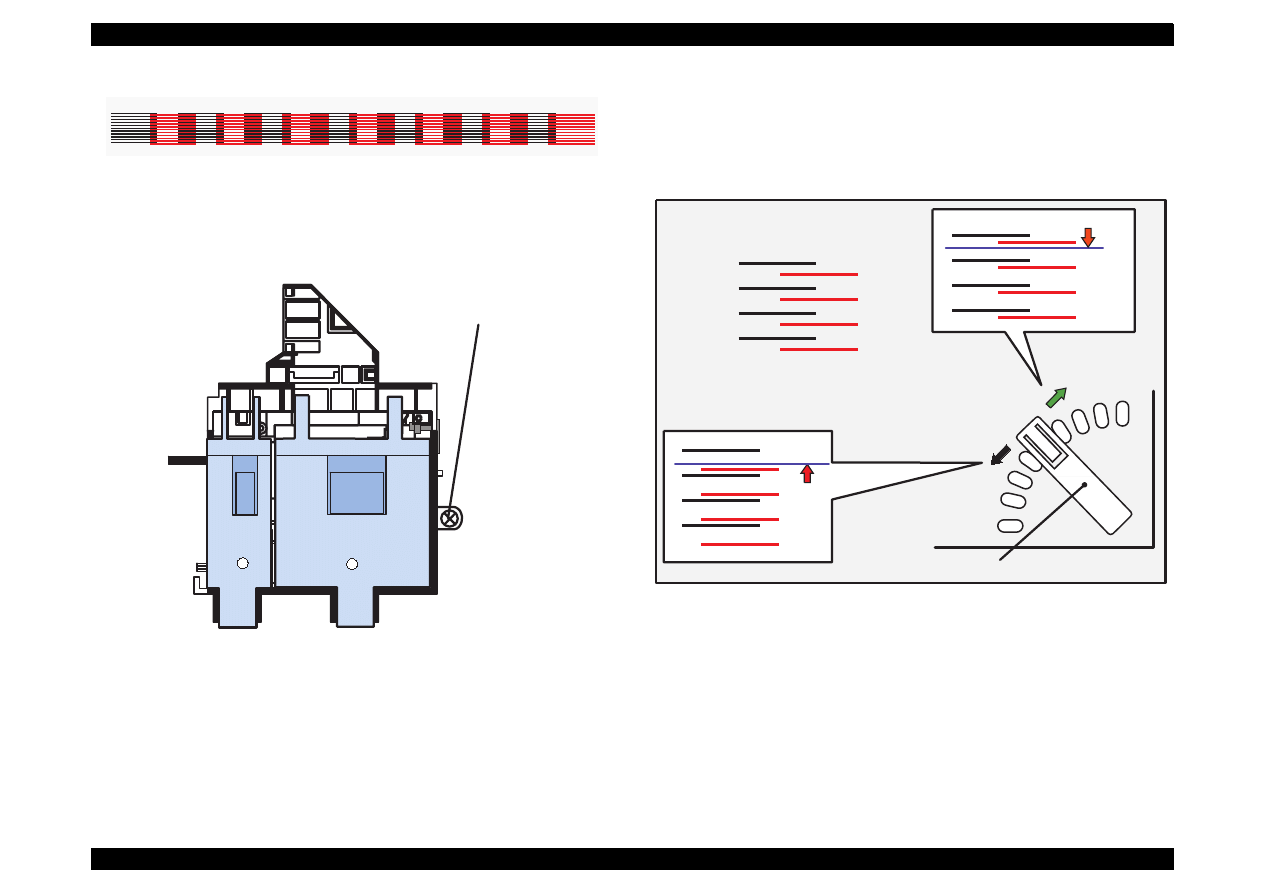
EPSON Stylus Color 440/640/740
Revision A
Chapter 5
Adjustment
149
Figure 5-28. Sample of Head Angular Adjustment Pattern
5. Loosen the printhead securing screw securing the printhead on the
carriage. (You don
'
t need to remove it completely.)
Figure 5-29. . Screw Position
NOTE: Make sure to loosen this screw. Otherwise, the printhead
angle will no change even if the adjusting lever moves.
6. Look at the black/magenta combination in the pattern and move the
adjusting lever to make the magenta lines stay between the black
lines with even space. The figure below shows how the pattern
changes as the adjusting lever moves right (rear) or left (front).
Figure 5-30.
Lever Operation and Corresponding Change in Pattern
Head Angular Adjustment Pattern (BK-M)
Printhead securing screw
To move this up,
Correct condition = evenly spaced
move the lever to
the left (front).
move the lever to the
right (rear).
Adjusting Lever
To move this down,

EPSON Stylus Color 440/640/740
Revision A
Chapter 5
Adjustment
150
7. After changing the position of the adjust lever, select Head angular
adjustment pattern again. The printer prints out a head angular
adjustment pattern and the screen automatically returns to the
Current Head Angular Confirmation Menu (1) shown in the figure
below.
Figure 5-31. Current Head Angular Confirmation Menu (1)
8. Verify the pattern on the printout again.
9. Repeat the procedures from Step 5 to Step9 until the combination
pattern of black/magenta is correct.
10. After completing the adjustment, tighten the loosened screw, and
reinstall the upper case only when you remove it.
M S - D O S P r o m p t - S C 6 4 0
A u t o
H e a d A n g u l a r A d j u s t m e n t
E s c : P r e v i o u s
H e a d A n g u l a r A d j u s t m e n t p a t t e r n
E n t e r : O K
N o t e :
T h e i n f o r m a t i o n p r o v i d e d i n t h i s s e r v i c e t o o l i s c o m m o n f o r t h e S t y l u s C o l o r 4 4 0 , 6 4 0 ,
a n d 7 4 0 e x c e p t f o r s o m e p r i n t e r s p e c i f i c i n f o r m a t i o n s u c h a s i n k c o u n t e r l i m i t s .
M o v e t h e c a r r i a g e t o t h e h e a d a n g u l a r a d j u s t m e n t p o s i t i o n .
R e t u r n t h e c a r r i a g e t o t h e h o m e p o s i t i o n .

EPSON Stylus Color 440/640/740
Revision A
Chapter 5
Adjustment
151
5.2.2.9 Bi-D Adjustment
You perform this adjustment to correct differences in printing positions,
which is caused by slippage of printing timing in right and left directions
during the Bi-directional printing. Therefore, you are required to perform
this adjustment after performing the following operations.
Replacing the Print mechanism
Replacing the main board
Replacing the CR motor
Replacing the Carriage Assembly
Replacing g the Printhead
1. Apply the main menu (Figure 5-21). (See Section 5.2.2.2.)
2. By using the Up/Down arrow key, select Adjustment in the main
menu.
3. By using the Up/Down arrow key, select Bi-Directional
Adjustment in the adjustment menu. (See Figure 5-19.) The
following screen appears.
Figure 5-32. Bi-D Adjustment Menu
4. By using the Up/Down arrow key, select Print the Bi-D adjustment
pattern on the screen, and the screen bellow appears.
Figure 5-33. Before Printing the Bi-D pattern
5. Press the Enter key. The printer starts printing a Bi-D adjustment
pattern. (See the sample pattern in the following page.)
NOTE:
As shown in the sample, gaps between passes are sometimes created
in different directions among patterns.
This unexpected change in direction is caused by an ink jet printer-
specific reason, which is an ink jet printer inevitably performs a
periodical cleaning specified by the flashing timer even during Bi-D
pattern printing, so that the printing direction suddenly changes.
However, this directional difference among Bi-D patterns should not be
considered, and you can always confirm and adjust the pattern correctly
by referring to gap amount only.
M S - D O S P r o m p t - S C 6 4 0
A u t o
B i - D i r e c t i o n a l A d j u s t m e n t
E s c : P r e v i o u s U p / D o w n : S e l e c t E n t e r : O K
P r i n t t h e B i - D a d j u s t m e n t p a t t e r n
A d j u s t
C h e c k p r e s e n t a d j u s t m e n t d a t a
N o t e :
T h e i n f o r m a t i o n p r o v i d e d i n t h i s s e r v i c e t o o l i s c o m m o n f o r t h e S t y l u s C o l o r 4 4 0 , 6 4 0 ,
a n d 7 4 0 e x c e p t f o r s o m e p r i n t e r s p e c i f i c i n f o r m a t i o n s u c h a s i n k c o u n t e r l i m i t s .
M S - D O S P r o m p t - S C 6 4 0
A u t o
E s c : P r e v i o u s E n t e r : O K
P r i n t a B i - D a d j u s t m e n t p a t t e r n f o r t h e p r e s e n t d a t a ?
2 0 0 C P S : p r e s e n t d a t a - 2 , p r e s e n t d a t a , p r e s e n t d a t a + 2
N o t e :
T h e i n f o r m a t i o n p r o v i d e d i n t h i s s e r v i c e t o o l i s c o m m o n f o r t h e S t y l u s C o l o r 4 4 0 , 6 4 0 ,
a n d 7 4 0 e x c e p t f o r s o m e p r i n t e r s p e c i f i c i n f o r m a t i o n s u c h a s i n k c o u n t e r l i m i t s .
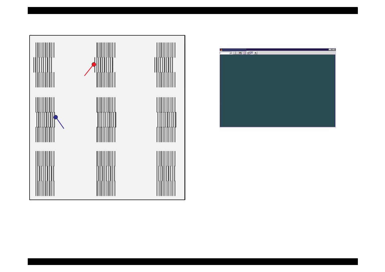
EPSON Stylus Color 440/640/740
Revision A
Chapter 5
Adjustment
152
Figure 5-34. Bi-D ADjustment Pattern Sample
6. By using the Up/Down key, select Adjust on the Bi-D adjustment
menu (Figure 5-32). Then the screen below appears.
Figure 5-35. Bi-D Value Input Menu
7. The value 0 (blue) appears in the center of the screen and changes
up/down every time you press the Up/Down arrow key. Using the
keys, apply the number for the most properly aligned pattern in the
Bi-D adjustment pattern print.
8. After you set the value correctly, press the Enter key, and the
program stores the selected value.
9. Press the Esc key once. The current screen returns to the Bi-D
adjustment menu. (See Figure 5-32.)
10. Repeat the procedure from Step3 to Step9 until the Bi-D adjustment
pattern is correct.
200 CPS Bi-D Pattern : Data = -2
200 CPS Bi-D Pattern : Data = 0
200 CPS Bi-D Pattern : Data = 2
Left Gap
Right Gap
M S - D O S P r o m p t - S C 6 4 0
A u t o
E s c : P r e v i o u s U p / D o w n : S e l e c t E n t e r : O K
S e l e c t a n a d j u s t m e n t v a l u e w i t h t h e U p / D o w n a r r o w k e y s .
2 0 0 C P S B i - D A d j u s t m e n t
0
N o t e :
T h e i n f o r m a t i o n p r o v i d e d i n t h i s s e r v i c e t o o l i s c o m m o n f o r t h e S t y l u s C o l o r 4 4 0 , 6 4 0 ,
a n d 7 4 0 e x c e p t f o r s o m e p r i n t e r s p e c i f i c i n f o r m a t i o n s u c h a s i n k c o u n t e r l i m i t s .

MAINTENANCE

EPSON Stylus Color 440/640/740
Revision A
Chapter 6
Maintenance
154
6.1 Overview
This section describes the points and the procedures for maintaining
the printer in its optimum condition.
6.1.1 Cleaning
This printer has no mechanical components which require regular
cleaning. Therefore, note that the points suggested below are only to
check for dirt, and perform appropriate cleaning if necessary.
Housing:
Use a clean soft cloth moistened with water and wipe off any dirt. If
the housing is stained with ink, use a cloth moistened with neutral
detergent to wipe it off.
Inside the printer:
Use a vacuum cleaner to remove any paper dust.
6.1.2 Service Maintenance
If print irregularity (missing dot, white line, etc.) has occurred or the
printer indicates “MAINTENANCE ERROR”, take the following actions
to clear the error.
Head Cleaning
The printer has a built-in head cleaning function and is activated
through the control panel operation.
1. Confirm that the printer is in stand-by state (the POWER indicator
is not blinking), and hold down the cleaning button on the control
panel for more than 3 seconds.
2. The printer enters the built-in cleaning sequence. (During the
sequence, the POWER indicator is blinking.)
Maintenance Error Clear
Ink is used for the operations such as cleaning as well as printing.
Therefore, the printer wastes certain amount of ink and counts the
amount of waste ink and drains it into the waste ink pad. Once the
amount of waste ink reaches the predefined limit, the printer
indicates “MAINTENANCE ERROR” and the waste ink pad should
be replaced.
(See Chapter 1 / Page 1-25 for details.)
C A U T I O N
Never use chemical solvents, such as thinner, to
clean the printer. These chemicals can damage the
components of the printer.
Be careful not to damage the components when you
attempt to clean the inside the printer.
Do not scratch surface of “ROLLER, ASSEMBLY, PF”.
(Use soft brush to wipe off any dusts, or use a soft
cloth moistened with alcohol.)
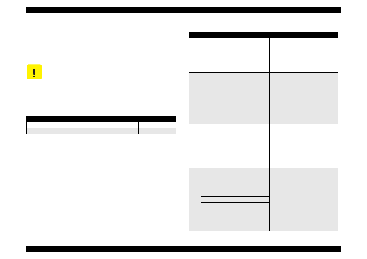
EPSON Stylus Color 440/640/740
Revision A
Chapter 6
Maintenance
155
6.1.3 Lubrication
The type and amount of oil and grease used to lubricated the printer
parts are determined based on the results of internal evaluations.
Therefore, be sure to apply the specified type and amount of oil and
grease to the specified part of the printer mechanism during servicing.
C A U T I O N
Never use oil and the grease other than those
specified in this manual. Use of different types of
lubricant can damage the printer and the
components.
Never apply larger amount of lubricant than specified
in this manual.
Table 6-1. Specified Lubricants
Type
Name
EPSON Code
Supplier
Grease
G-26
B702600001
EPSON
Oil
O-12
1038991
EPSON
Table 6-2. Lubrication Point
No.
Standard
Remarks
1
<Lubrication Point>
Contact between “ROLLER, PF” and
“PAPER GUIDE, REAR”
Do not put grease around the paper
path.
Use a syringe to apply it.
Apply grease while rotating “GEAR,
67.2”.
<Lubricant Type> G-26
<Lubrication Amount>
A half turn of “ROLLER, PF”
2
<Lubrication Point>
Contact points between “PAPER
GUIDE, FRONT” and each roller:
“ROLLER, PF” (1 point)
“ROLLER, EXIT” (2 points)
Lubricate the contact points between
the hooks on “PAPER GUIDE,
FRONT” and each roller.
Avoid applying grease around the
paper path.
Use a syringe to apply it.
<Lubricant Type> G-26
<Lubrication Amount>
10-mm long
2-mm long
3
<Lubrication Point>
Contact points between the carriage
assembly and “FRAME, UPPER”
Verify that the carriage moves
smoothly after lubricating it.
Use a syringe to apply it.
<Lubricant Type> G-26
<Lubrication Amount>
Range from the HP sensor
installation point to the point where
“GUIDE PLATE, CABLE” is attached.
4
<Lubrication Point>
Gears:
“GEAR, 67.2”
“COMBINATION GEAR, 8, 14.4”
“GEAR, 23.2”
Rotate the gears after applying
grease to evenly distribute it.
Use a syringe to apply it.
<Lubricant Type> G-26
<Lubrication Amount>
1/4 of gear tooth
1/3 of gear tooth
1/3 of gear tooth
1/3 of gear tooth
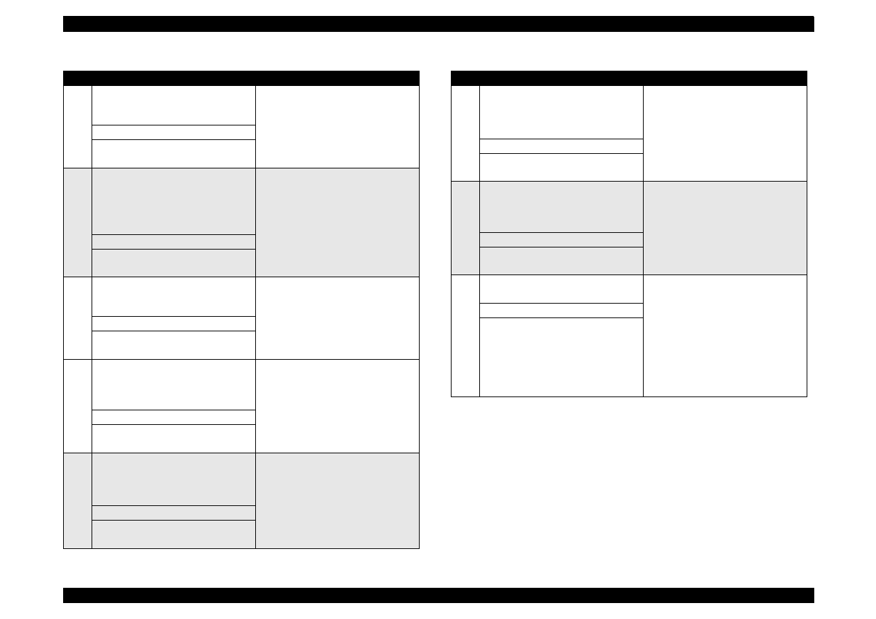
EPSON Stylus Color 440/640/740
Revision A
Chapter 6
Maintenance
156
5
<Lubrication Point>
The shaft for “GEAR, 16, 40.8” on
“FRAME, LEFT”
Use a syringe to apply it.
<Lubricant Type> G-26
<Lubrication Amount>
Approximately 5-mm long
6
<Lubrication Point>
Bushings for “ROLLER, PF”
Left: Inside the bushing
Right: Inside the bushing (near the
pump assembly)
For the right bushing, apply it from
the paper path side, and wipe off any
grease sticking out to the cap
assembly side.
Rotate “ROLLER, PF” after applying
grease to evenly distribute it in the
bushing.
Use a syringe to apply it.
<Lubricant Type> G-26
<Lubrication Amount>
Approximately 3 mm diametrically
7
<Lubrication Point>
Both Left/Right Bushings for
“ROLLER, EXIT”
Avoid applying grease around the
paper path.
Use a syringe to apply it.
<Lubricant Type> G-26
<Lubrication Amount>
Evenly apply inside the bushings.
8
<Lubrication Point>
Contact points between “HOLDER,
PULLEY, DRIVEN” and “FRAME,
UPPER”
Verify that the holder slides only with
spring force after applying grease.
Use a syringe to apply it.
<Lubricant Type> G-26
<Lubrication Amount>
2-mm long for each point
9
<Lubrication Point>
ASF;
The round hole in the right frame of
ASF (to hold the roller shaft)
Avoid applying grease to “ROLLER,
ASSEMBLY, LD”.
<Lubricant Type> G-26
<Lubrication Amount>
Evenly apply inside the hole.
Table 6-2. Lubrication Point
No.
Standard
Remarks
10
<Lubrication Point>
ASF;
Contact points between “HOPPER”
and “LEVER, HOPPER, RELEASE”
Completely wipe off any grease
sticking out to the inner side of ASF.
<Lubricant Type> G-26
<Lubrication Amount>
Evenly apply lubrication to the points.
11
<Lubrication Point>
The round cutout in the left frame of
ASF (“GEAR, 34” is inserted to the
cutout.)
Completely wipe off any grease
sticking out to the inner side of ASF.
<Lubricant Type> G-26
<Lubrication Amount>
Evenly apply inside the hole
12
<Lubrication Point>
Oil pad in the carriage assembly
Lubricate the oil pad only when;
*Replacing the carriage assembly
*Replacing the oil pad
Use a precise syringe to apply it. If
you accidentally apply too much oil to
the oil pad, throw the pad away and
take a new one again.
Leave the oil pad for a while to wait
until oil is evenly infiltrated, then
install it on the carriage assembly.
<Lubricant Type> O-12
<Lubrication Amount>
0.7 cc
Note:
This is the amount to be applid to a
new oil pad.
Table 6-2. Lubrication Point
No.
Standard
Remarks
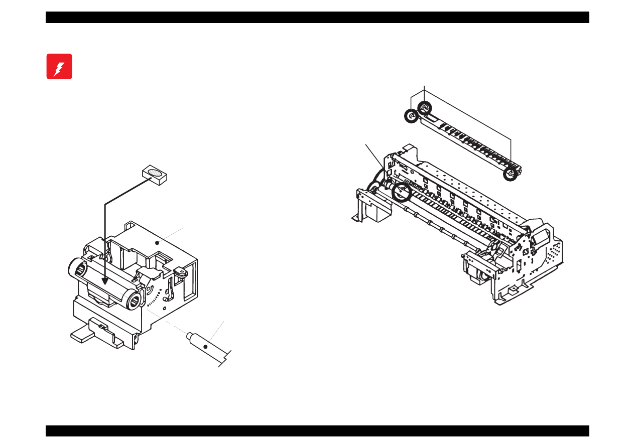
EPSON Stylus Color 440/640/740
Revision A
Chapter 6
Maintenance
157
W A R N I N G
Never apply oil to the CR guide shaft directly. This
may cause fatal damage to the components of the
printer.
Avoid applying oil excessively to the oil pad. This
may cause fatal damage to the components of the
printer.
N o . 1 2
( O i l p a d )
* N e v e r a p p l y t h e o i l e x c e e d i n g 0 . 6 c c .
C a r r i a g e A s s e m b l y
( b o t t o m v i e w )
" S H A F T , C R , G U I D E "
N o . 1
N o . 2
1 0 m m
2 m m
2 m m
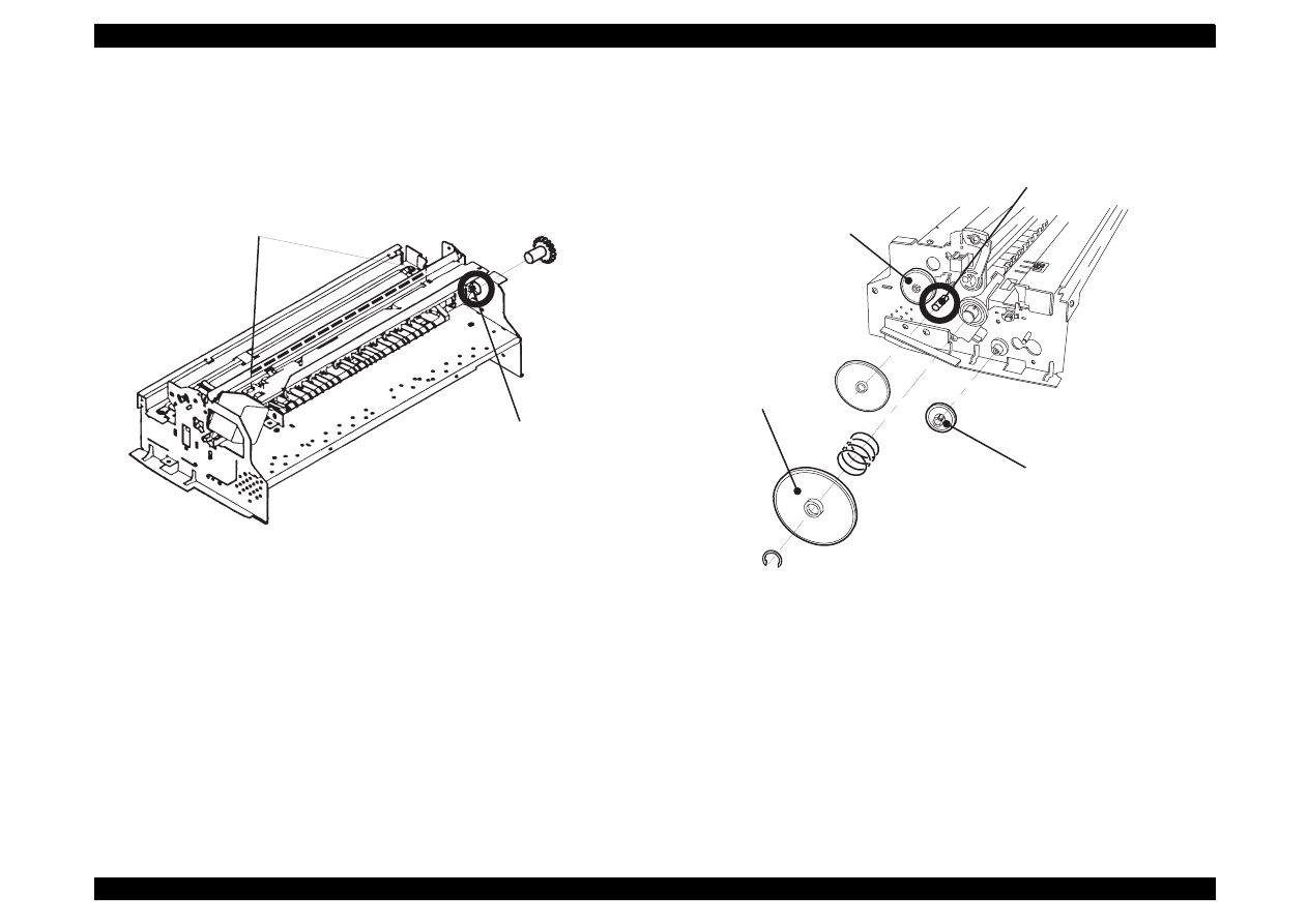
EPSON Stylus Color 440/640/740
Revision A
Chapter 6
Maintenance
158
N o . 3
N o . 1 1
" G E A R , 3 4 "
N o . 5
N o . 4
N o . 4
N o . 4
" G E A R , 2 3 . 2 "
" G E A R , 1 6 , 4 0 . 8 "
" G E A R , 6 7 . 2 "
" C O M B I N A T I O N G E A R ,
8 , 1 4 . 4 "
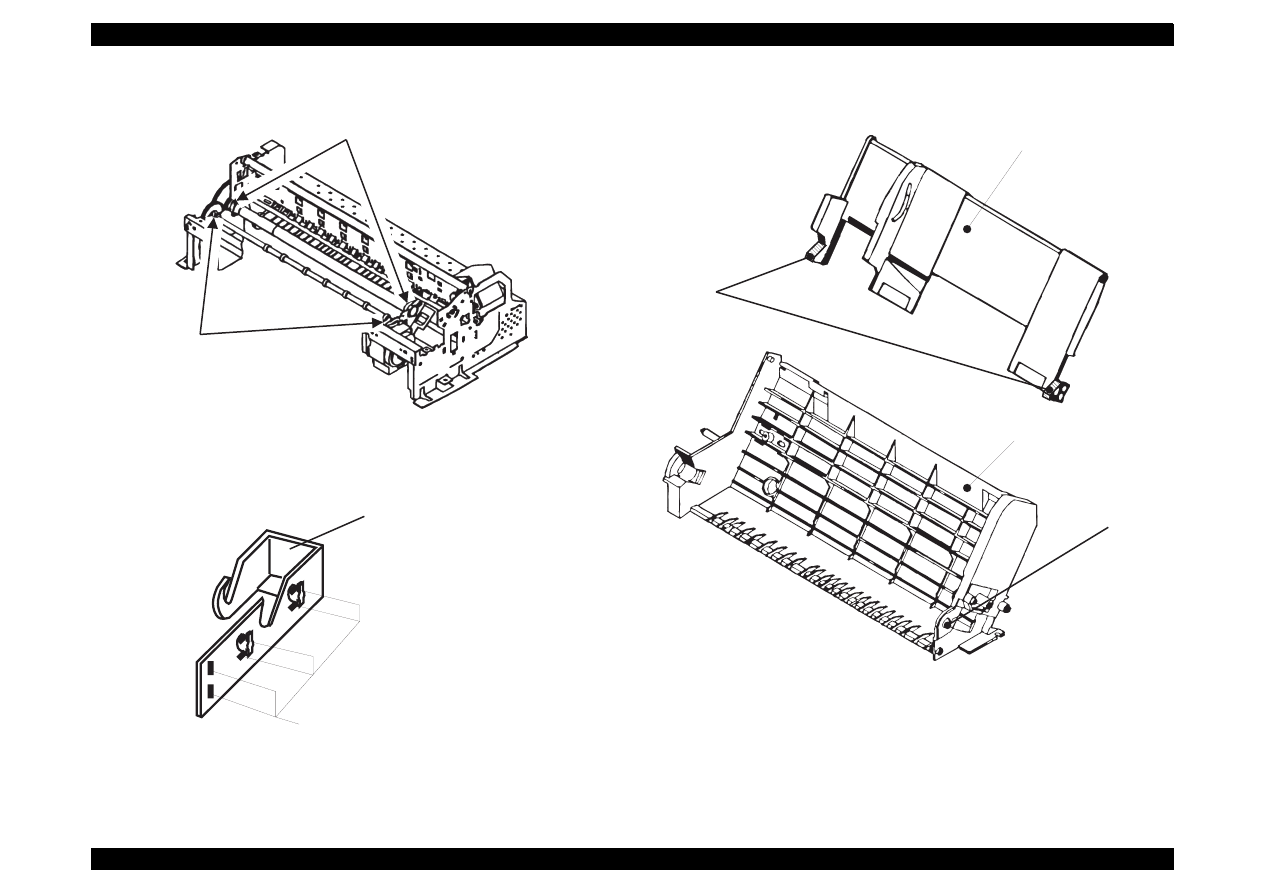
EPSON Stylus Color 440/640/740
Revision A
Chapter 6
Maintenance
159
N o . 6
N o . 7
N o . 8
" H O L D E R , P U L L E Y , D R I V E N "
N o . 9
N o . 1 0
" H O P P E R , A S S E M B L Y "
" F R A M E , A S F "

APPENDIX

EPSON Stylus Color 440/640/740
Revision A
Chapter 7
Appendix
161
A.1 Connector Summary
This section gives information on connectors and their pin assignment.
Since all connectors and their pin assignments except for CN8
(printhead) are common for Stylus Color 440 and Stylus Color 640, they
are included in one section (
Section A.1.1
.) Refer to
Section A.1.2
for
the connector summary for Stylus Color 740. Each section includes the
following information.
Section A.1.1 (Stylus Color 440/640)
C206MAIN-B, C255MAIN (Stylus Color 440)
C256MAIN (Stylus Color 640)
C206PSB/PSE (Stylus Color 440, Stylus Color 640)
Printer Mechanism
Section A.1.2 (Stylus Color 740)
C257MAIN
C257PSB/PSE
Printer mechanism
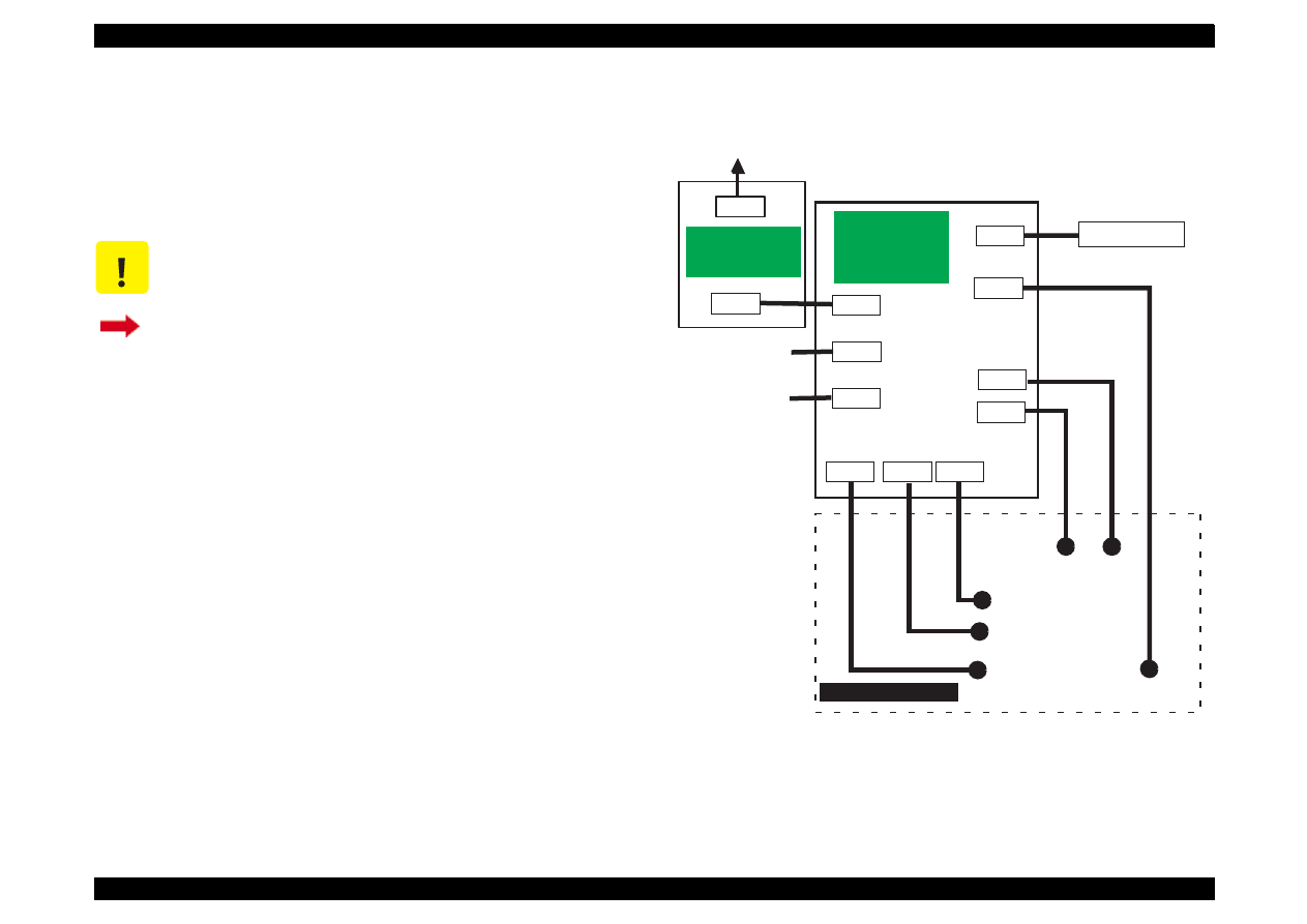
EPSON Stylus Color 440/640/740
Revision A
Chapter 7
Appendix
162
A.1.1 Connector Summary
(Stylus Color 440/640)
This section provides information on connectors in the main units of the
Stylus Color 440 and Stylus Color 640. Figure 1 shows how the main
component units are connected.
Figure A-1. Cable Connection of Stylus Color 440/640
C A U T I O N
Information contained in this section only applies to
Stylus Color 440 and Stylus Color 640.
If you need information on Stylus Color 740, go to
Section A.1.2.
CN1
CN2
AC
CN10
CN3
CN8
C206MAIN-B
C255MAIN
C256MAIN
(Main Board)
CN1
CN2
CN6
CN7
CN11
CN5
CN4
Control Panel
Print Head
CR
Motor
PF
Motor
ASF Sensor
HP Sensor
PE Sensor
Parallel I/F
Printer Mechanism
C206PSB/PSE
(Power Supply
Board)
Serial I/F
(Not mounted)
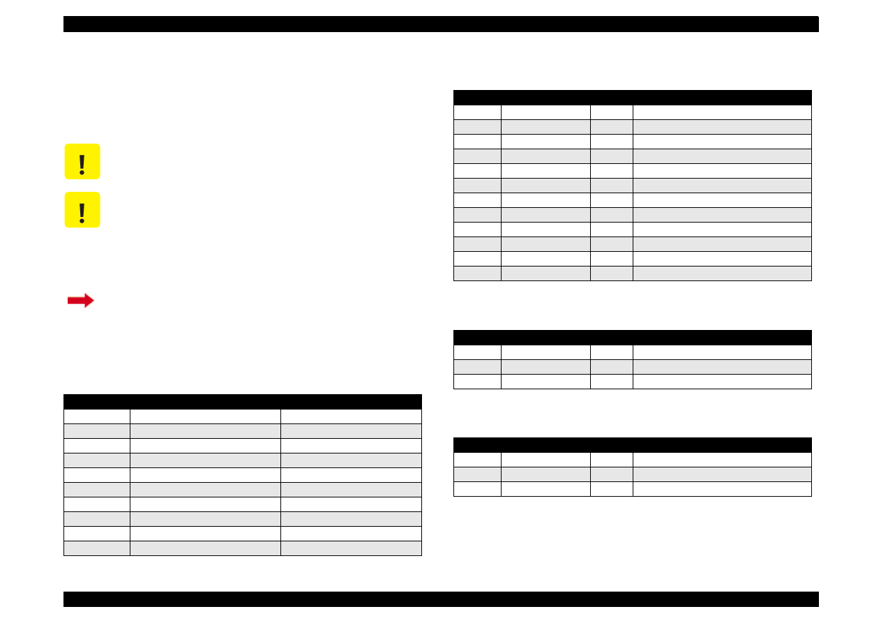
EPSON Stylus Color 440/640/740
Revision A
Chapter 7
Appendix
163
A.1.1.1 Connector Pin Assignment
(Stylus Color 440 and Stylus Color 640)
Tables in this section provide connector pin assignments of the
C206MAIN-B, C255MAIN and C256MAIN, the main boards equipped
with Stylus Color 440 and Stylus Color 640.
C A U T I O N
Information contained in this section only applies to
Stylus Color 440 and Stylus Color 640.
C A U T I O N
Pin assignments for all connectors but CN8 (Printhead)
are common. Therefore they are combined in the same
tables. As for CN8 (printhead), separate tables are
provided as shown below.
Table A-7: CN8 for C206MAIN-B, C255MAIN
Table A-8: CN8 for C256MAIN
If you need information on Stylus Color 740, go to
Section A.1.2.1.
Table A-1.
Connector Summary of C206MAIN-B/C255MAIN/C256MAIN
Connector
Function
Table to refer to
CN1
Parallel I/F connector
Chapter 1/Table 1-10
CN2
Serial I/F connector
Chapter 1/Table 1-16
CN3
To Control panel
Table A-2
CN4
To PE sensor
Table A-3
CN5
To HP sensor
Table A-4
CN6
To CR motor
Table A-5
CN7
To PF motor
Table A-6
CN8
To Printhead
Table A-7
CN10
To Power supply board
CN11
To ASF sensor
Table A-2. Connector CN3
Pin
Signal Name
I/O
Function
1
LED0
Out
LED drive signal (0)
2
GND
----
Ground
3
LED1
Out
LED drive signal (1)
4
GND
----
Ground
5
LED2
Out
LED drive signal (2)
6
+5V
----
Logic power supply
7
+5V
----
Logic power supply
8
LED4
Out
LED drive signal (4)
9
SW1
In
Panel switch input (1)
10
PSC
In
Power on/off switch
11
SW0
In
Panel switch on/off (0)
12
SW2
In
Panel switch on/off (2)
Table A-3. Connector CN4
Pin
Signal Name
I/O
Function
1
PE
In
Sensor detect signal
2
GND
---
Ground
3
PEV
---
Sensor power supply (+5V)
Table A-4. Connector CN5
Pin
Signal Name
I/O
Function
1
HP
In
Sensor detect signal
2
GND
---
Ground
3
HPV
---
Sensor power supply(+5V)
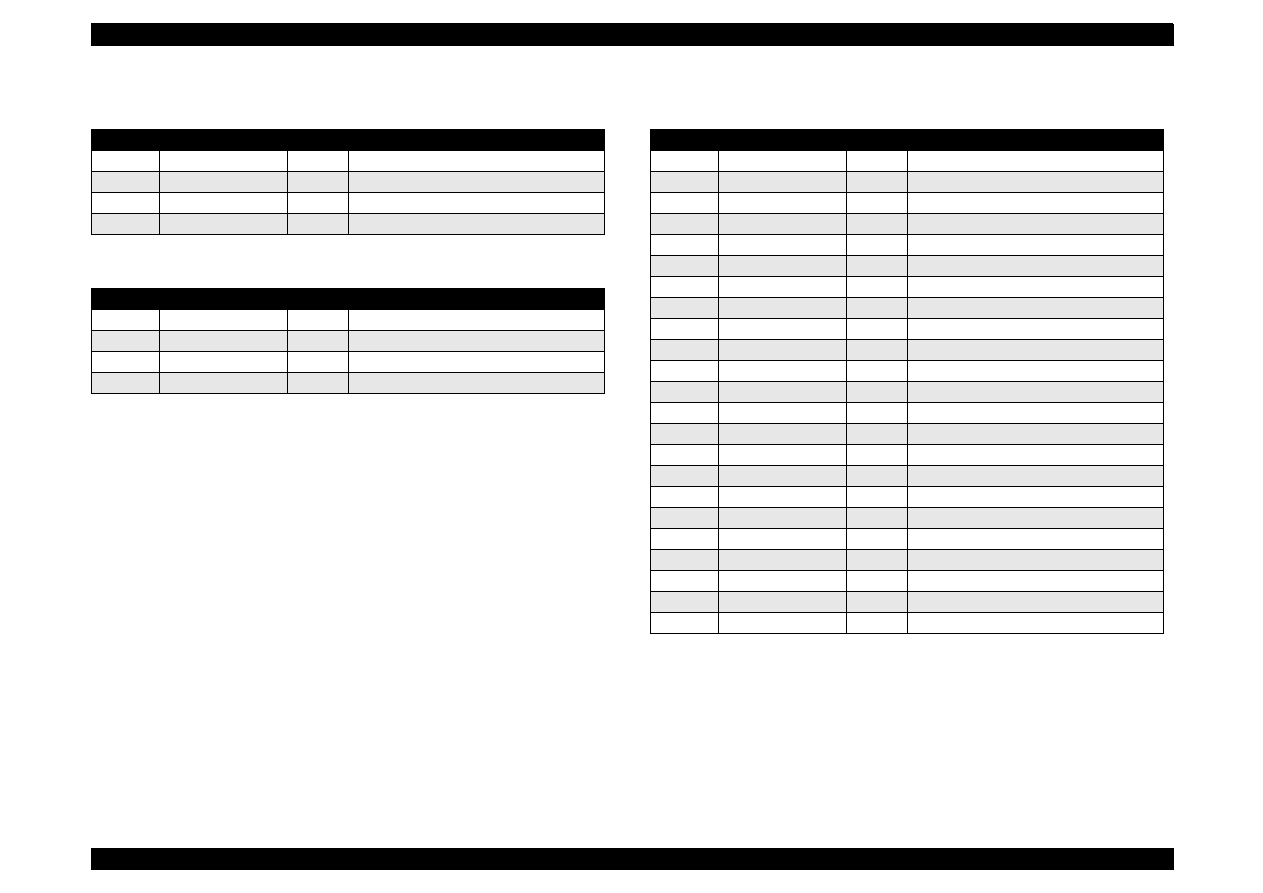
EPSON Stylus Color 440/640/740
Revision A
Chapter 7
Appendix
164
Table A-5. Connector CN6
Pin
Signal Name
I/O
Function
1
CRA
Out
Phase drive signal (A)
2
CRB
Out
Phase drive signal (B)
3
CR-A
Out
Phase drive signal (-A)
4
CR-B
Out
Phase drive signal (-B)
Table A-6. Connector CN7
Pin
Signal Name
I/O
Function
1
PFA
Out
Phase drive signal (A)
2
PFB
Out
Phase drive signal (B)
3
PF-A
Out
Phase drive signal (-A)
4
PF-B
Out
Phase drive signal (-B)
Table A-7. Connector CN8
(C206MAIN-B, C255MAIN
)
Pin
Signal Name
I/O
Function
1
BCO
In
Black ink cartridge detect signal
2
CCO
In
Color ink cartridge detect signal
3
THM
In
Thermistor detect signal
4
GND
---
Ground
5
LAT
Out
Head data latch pulse output
6
GND
---
Ground
7
SI2
Out
Head data output (2)
8
GND
---
Ground
9
SI1
Out
Head data output (1)
10
GND
---
Ground
11
CLK
Out
Head data output (1)
12
GND
---
Ground
13
NCHG
Out
Head all on pulse output
14
GND
---
Ground
15
VDD
---
Logic power supply (+5V)
16
GND2
---
Ground
17
GND2
---
Ground
18
GND2
---
Ground
19
COM
---
Head drive power supply
20
COM
---
Head drive power supply
21
COM
---
Head drive power supply
22
VHV
---
Head drive voltage control signal
23
VHV
---
Head drive voltage control signal
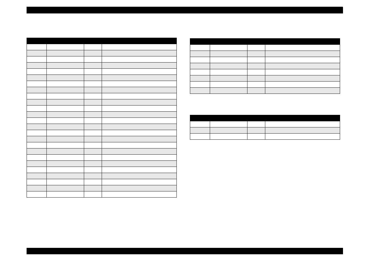
EPSON Stylus Color 440/640/740
Revision A
Chapter 7
Appendix
165
Table A-8. Connector CN8
(C256MAIN)
Pin
Signal Name
I/O
Function
1
BCO
In
Black ink cartridge detect signal
2
CCO
In
Color ink cartridge detect signal
3
THM
In
Thermistor detect signal
4
GND
---
Ground
5
LAT
Out
Head data latch pulse output
6
GND
---
Ground
7
SI3
Out
Head data output (3)
8
GND
---
Ground
9
SI2
Out
Head data output (2)
10
GND
---
Ground
11
SI1
Out
Head data output (1)
12
GND
---
Ground
13
CLK
Out
Clock pulse for head data transfer
14
GND
---
Ground
15
NCHG
Out
Head all on pulse output
16
GND
---
Ground
17
VDD
---
Logic power supply (+5V)
18
GND2
---
Ground
19
GND2
---
Ground
20
GND2
---
Ground
21
COM
---
Head drive power supply
22
COM
---
Head drive power supply
23
COM
---
Head drive power supply
24
VHV
---
Head drive voltage control signal
25
VHV
---
Head drive voltage control signal
Table A-9. Connector CN10
Pin
Signal Name
I/O
Function
1
+42V
---
Mechanism drive power supply
2
+42V
---
Mechanism drive power supply
3
GND
---
Ground
4
GND
---
Ground
5
PSC
Out
Power supply switch output signal
6
GND
----
Ground
7
GND
---
Ground
8
+5V
---
Logic power supply
Table A-10. Connector CN11
Pin
Signal Name
I/O
Function
1
ASF
In
Sensor detect signal
2
GND
---
Ground
3
ASFV
---
Sensor power supply (+5V)
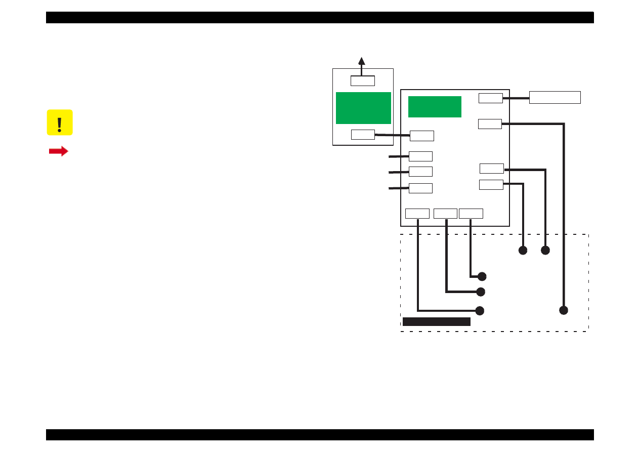
EPSON Stylus Color 440/640/740
Revision A
Chapter 7
Appendix
166
A.1.2 Connector Summary
for Stylus Color 740
This section contains information on connectors in the main units of
Stylus Color 740. Figure 2 shows how the main component units of the
Stylus Color 740 are connected.
Figure A-2. Cable Connection of the Stylus Color 740
C A U T I O N
Information contained in this section only applies to
Stylus Color 740.
If you need information on Stylus Color 440 and Stylus
Color 640, return to Section A.1.1.
CN1
CN2
AC
CN10
CN11
CN9
C257MAIN
(Main Board)
CN1
CN2
CN7
CN8
CN6
CN4
CN5
Control Panel
Print Head
CR
Motor
PF
Motor
ASF Sensor
HP Sensor
PE Sensor
Parallel I/F
Serial I/F
Printer Mechanism
C257PSB/PSE
C257PSK
(Power Supply
Board)
CN3
USB I/F
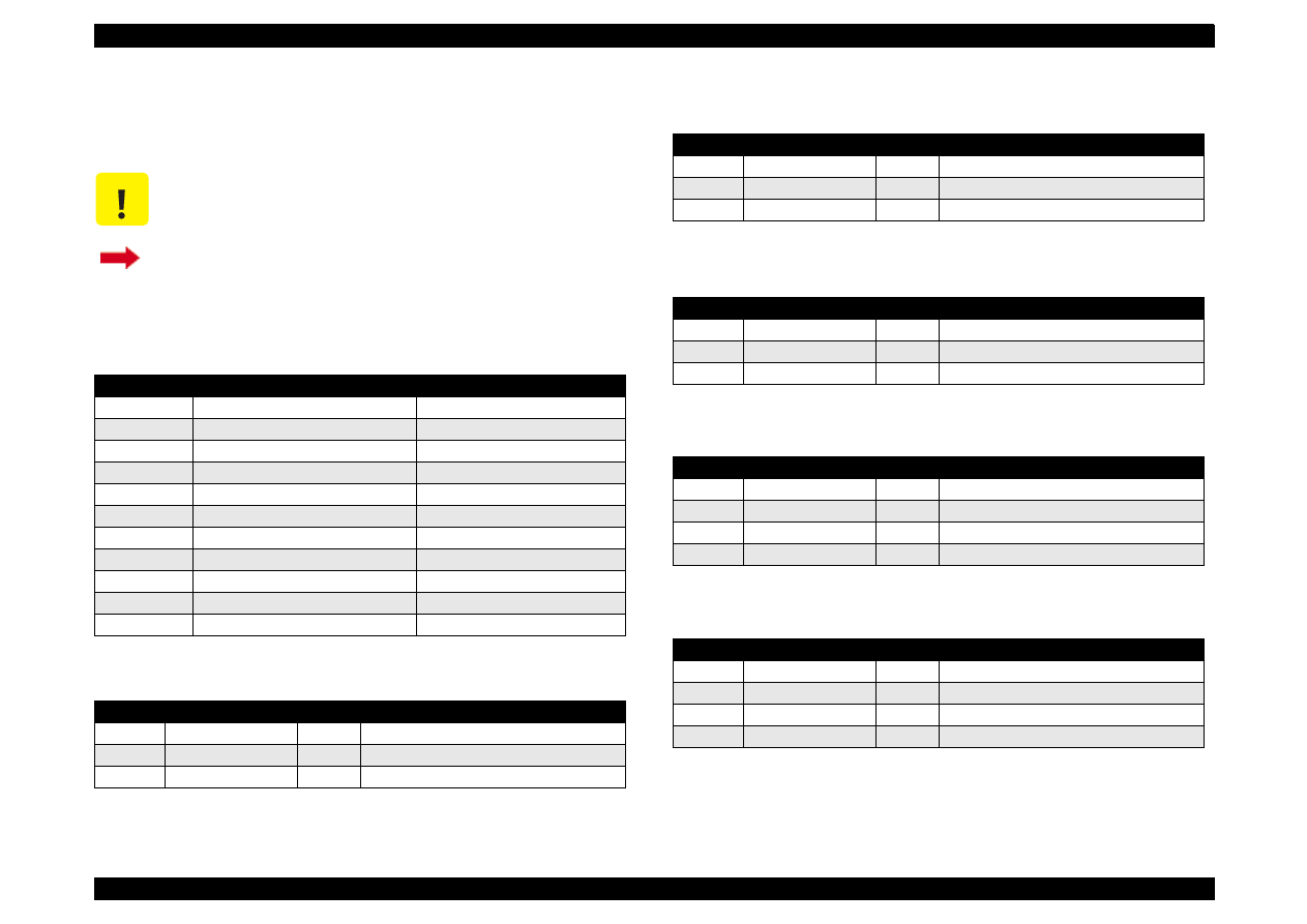
EPSON Stylus Color 440/640/740
Revision A
Chapter 7
Appendix
167
A.1.2.1 Connector Pin Assignment
(Stylus Color 740)
Tables in this section provide connector pin assignments of the
C257MAIN, the main board equipped with Stylus Color 740.
C A U T I O N
Information contained in this section only applies to
Stylus Color 740.
If you need information on Stylus Color 440 and Stylus
Color 640, return to Section A.1.1.1.
Table A-11. Connector Summary of C257MAIN
Connector
Function
Table to refer to
CN1
Parallel I/F connector
Chapter 1/Table 1-10
CN2
Serial I/F connector
Chapter 1/Table 1-16
CN3
SUB I/F connector
Chapter 1/Table 1-18
CN4
To HP sensor
CN5
To PE sensor
CN6
To ASF sensor
CN7
To CR motor
CN8
To PF motor
CN9
To Printhead
CN10
To Power supply board
CN11
To Control panel
Table A-12. Connector CN4
Pin
Signal Name
I/O
Function
1
HP
In
Sensor detect signal
2
GND
---
Ground
3
HPV
---
Sensor power supply(+5V)
Table A-13. Connector CN5
Pin
Signal Name
I/O
Function
1
PE
In
Sensor detect signal
2
GND
---
Ground
3
PEV
---
Sensor power supply (+5V)
Table A-14. Connector CN6
Pin
Signal Name
I/O
Function
1
ASF
In
Sensor detect signal
2
GND
---
Ground
3
ASFV
---
Sensor power supply (+5V)
Table A-15. Connector CN7
Pin
Signal Name
I/O
Function
1
CRA
Out
Phase drive signal (A)
2
CR-A
Out
Phase drive signal (-A)
3
CRB
Out
Phase drive signal (B)
4
CR-B
Out
Phase drive signal (-B)
Table A-16. Connector CN8
Pin
Signal Name
I/O
Function
1
PFA
Out
Phase drive signal (A)
2
PFB
Out
Phase drive signal (B)
3
PF-A
Out
Phase drive signal (-A)
4
PF-B
Out
Phase drive signal (-B)
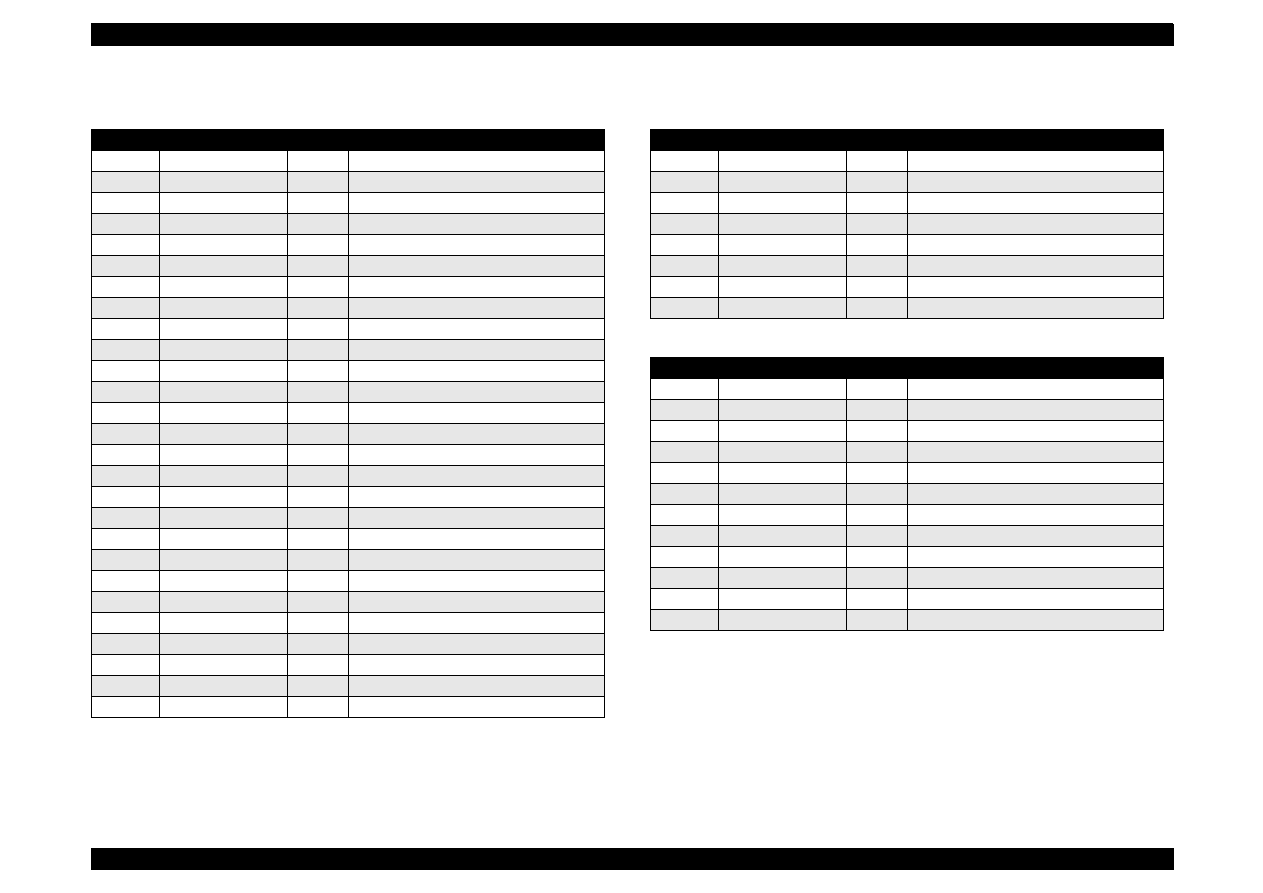
EPSON Stylus Color 440/640/740
Revision A
Chapter 7
Appendix
168
Table A-17. Connector CN9
Pin
Signal Name
I/O
Function
1
BCO
In
Black ink cartridge detect signal
2
CCO
In
Color ink cartridge detect signal
3
THM
In
Thermistor detect signal
4
GND
---
Ground
5
LAT
Out
Head data latch pulse output
6
GND
---
Ground
7
SI6
Out
Head data output (6)
8
SI5
Out
Head data output (5)
9
SI4
Out
Head data output (4)
10
SI3
Out
Head data output (3)
11
SI2
Out
Head data output (2)
12
SI1
Out
Head data output (1)
13
GND
---
Ground
14
CLK
Out
Clock pulse for head data transfer
15
GND
---
Ground
16
NCHG
Out
Head all on pulse output
17
GND
---
Ground
18
VDD
---
Logic power supply (+5V)
19
GND2
---
Ground
20
GND2
---
Ground
21
GND2
---
Ground
22
GND2
---
Ground
23
COM
---
Head drive power supply
24
COM
---
Head drive power supply
25
COM
---
Head drive power supply
26
COM
---
Head drive power supply
27
VHV
---
Head drive voltage control signal
Table A-18. Connector CN10
Pin
Signal Name
I/O
Function
1
+42V
---
Mechanism drive power supply
2
+42V
---
Mechanism drive power supply
3
GND
---
Ground
4
GND
---
Ground
5
PSC
Out
Power supply switch output signal
6
GND
----
Ground
7
GND
---
Ground
8
+5V
---
Logic power supply
Table A-19. Connector CN11
Pin
Signal Name
I/O
Function
1
SW2
In
Panel switch on/off (2)
2
SW0
In
Panel switch on/off (0)
3
PSC
In
Power on/off switch
4
SW1
In
Panel switch input (1)
5
LED3
Out
LED drive signal (3)
6
+5V
----
Logic power supply
7
+5V
----
Logic power supply
8
LED2
Out
LED drive signal (2)
9
GND
----
Ground
10
LED1
Out
LED drive signal (1)
11
GND
----
Ground
12
LED0
Out
LED drive signal (0)
EPSON Stylus Color 440/640/740
Revision A
Chapter 7
Appendix
169
A.2 EEPROM Address Map
This section contains EEPROM map for Stylus Color 440/640 and
Stylus Color 740. As it is in Section A.2, this section is separated in 2
parts as shown below. Therefore, be sure to refer to the correct section
depending on the printer model.
A.2.1 EEPROM ADDRESS Map
(Stylus Color 440/
640)
This section provides EEPROM address map for the Stylus Color 440
and Stylus Color 640. Since the contents of the EEPROM maps of the
main boards (C206MAIN-B, C255MAIN, and C256MAIN) are mostly
common, they are combined into one table except for some addresses.
Section A.2.1
EEPROM map for Stylus Color 440 and Stylus Color 640
Section A.2.2
EEPROM map for Stylus Color 740
C A U T I O N
EEPROM map in this section only applies to Stylus
Color 440 and Stylus Color 640.
C A U T I O N
Be aware that some address rows are separated for
Stylus Color 440 and Stylus Color 640, and each row
stores the model-specific information. Therefore, be
sure to follow the correct row for the model.
If you need EEPROM map for Stylus Color 740, go to
Section A.2.2.
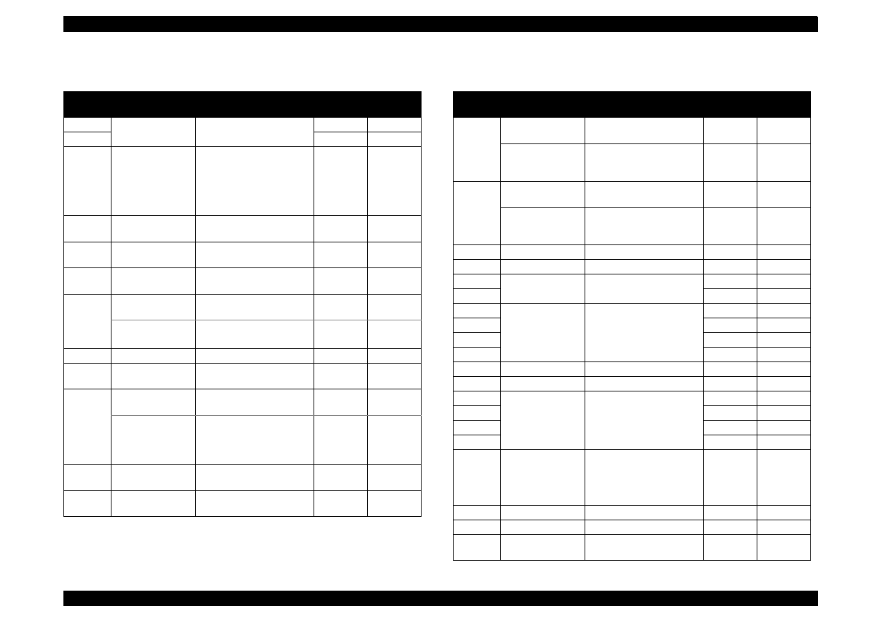
EPSON Stylus Color 440/640/740
Revision A
Chapter 7
Appendix
170
Table A-20.
Stylus Color 440/640
EEPROM Address Map
Address
Explanation
Setting
QPIT
Settings
Factory
Settings
00H
Password 0
54H
-
01H
0FH
-
02H
Market
0: Word
1: Japan
2: Custom (MJ-)
∗∗
3: Custom (Stylus Color)
∗∗
4: Custom (other name)
∗∗
00H
(
∗
1)
(*3)
03H
1st dot adjustment -40
≤
n
≤
40
(by 1/1440 inch)
00H
(
∗
1)
04H
Bi-D adjustment
data
-36
≤
n
≤
36
(by 1/1440 inch)
00H
(
∗
1)
05H
Uni-D adjustment
data
-36
≤
n
≤
36
(by 1/1440 inch)
00H
(
∗
1)
06H
Stylus Color 440
Reserved
00H
-
Stylus Color 640
CG
0: STD
1: NLSP
00H
(
∗
1)
07H
Reserved
00H
-
08H
Carriage speed
adjustment data
-4
≤
n
≤
4
(by G.A timer unit)
00H
(
∗
1)
09H
Stylus Color 440
Reserved
00H
-
Stylus Color 640
Carriage speed
adjustment data
for 1440 dpi
-4
≤
n
≤
4
(by G.A timer unit)
00H
(
∗
1)
0AH
Head actuator
rank ID for VhN
12H
(
∗
1)
0BH
Head actuator
rank ID for Twh2
01H
(
∗
1)
Table A-21.
Stylus Color 440/640
EEPROM Address Map (Continued)
Address
Explanation
Setting
QPIT
Settings
Factory
Settings
0CH
Stylus Color 440
Reserved
00H
(
∗
1)
Stylus Color 640
Head actuator
rank ID for VhM
10H
(
∗
1)
0DH
Stylus Color 440
Reserved
00H
-
Stylus Color 640
Head actuator
rank ID for VhMS
00H
(
∗
1)
0EH
Reserved
00H
-
0FH
Reserved
00H
-
10H
Password 1
5AH
-
11H
0FH
-
12H
Custom EEPROM
sub number
00H
00H
13H
00H
00H
14H
00H
00H
15H
00H
00H
16H
Reserved
00H
-
17H
Reserved
00H
-
18H
CPSI password
00H
00H
19H
00H
00H
1AH
00H
00H
1BH
00H
00H
1CH
CPSI flags
bit7: CPSI license
0: Disable, 1: Enable
bit6: CPSI Font license
0: Disable, 1: Enable
00H
00H
1DH
Reserved
00H
-
1EH
Reserved
00H
-
1FH
EEPROM
Revision
42H
-
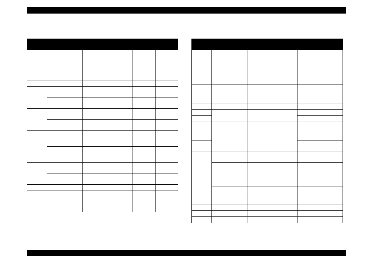
EPSON Stylus Color 440/640/740
Revision A
Chapter 7
Appendix
171
Table A-22.
Stylus Color 440/640
EEPROM Address Map (Continued)
Address
Explanation
Setting
QPIT
Settings
Factory
Settings
20H
Password 2
5AH
-
21H
0FH
-
22H
Interface selection 0: Auto, 1: Parallel
2: Serial
00H
00H
∗
2
23H
Interface wait time 0 to 255 (by second)
0AH
0AH
24H
Parallel I/F speed
0: High speed 1: Normal
00H
00H
25H
Stylus Color 440
Reserved
00H
-
Stylus Color 640
Font
0: Couier
00H
00H
26H
Stylus Color 440
Reserved
00H
-
Stylus Color 640
Pitch
0: 10 cpi
00H
00H
27H
Stylus Color 440
Print direction
control
0: Bi-D
1: Uni-D
2: Auto
02H
02H
Stylus Color 640
Print direction
control
2: Auto
02H
02H
28H
Stylus Color 440
CG table
0: PC437 1: PC850
00H
(
∗
1)
Stylus Color 640
CG table
0: PC437 1: PC850
08H
00H
29H
Reserved
00H
-
2AH
Auto LF/Network
I/F mode
bit1: Network I/F mode
(0=off, 1=on)
bit0: Auto line feed
(0=off, 1=on)
00H
00H
Table A-23.
Stylus Color 440/640
EEPROM Address Map (Continued)
Address
Explanation
Setting
QPIT
Settings
Factory
Settings
2BH
Panel mask
function
bit7: Enable Self Test
bit6: Enable Hex Dump
bit5: Extended settings
bit2: Cleaning
bit1: Replace I/C
bit0: Load/Eject
00H
00H
(*3)
2CH
Reserved
00H
-
2DH
Reserved
00H
-
2EH
Reserved
00H
-
2FH
Reserved
00H
-
30H
Password 3
5AH
-
31H
0FH
-
32H
Reserved
00H
-
33H
Reserved
00H
-
34H
Top margin
42 to 44X360
(by 1/360 inch)
78H
78H (*3)
35H
00H
00H
(*3)
NOTE
36H
37H
Stylus Color 440
Reserved
00H
-
Stylus Color 640
Bottom margin
1244 to 44x360
(by 1/360 inch)
36H=F0H
37H=1EH
36H=F0H
37H=1EH
38H
Stylus Color 440
Reserved
00H
-
39H
Stylus Color 640
Page length
1244 to 44x360
(by 1/360 inch)
38H=F0H
39H=1EH
38H=F0H
39H=1EH
3AH
Reserved
00H
-
3BH
Reserved
00H
-
3CH
Reserved
00H
-
3DH
Reserved
00H
-
NOTE: The reference *3 for the address 35H only applies to Stylus Color 440.
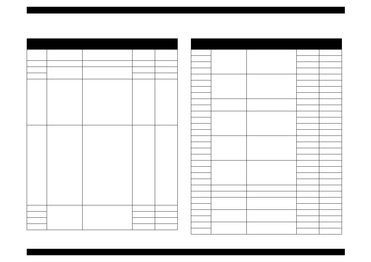
EPSON Stylus Color 440/640/740
Revision A
Chapter 7
Appendix
172
Table A-24.
Stylus Color 440/640
EEPROM Address Map (Continued)
Address
Explanation
Setting
QPIT
Settings
Factory
Settings
3EH
CR-phase of
Home
00H
00H
3FH
ERROR Number
00H
00H
40H
Password 4
5AH
-
41H
0FH
-
42H
Ink flags
bit7: Reserved
bit6: black
“one time”
bit5: color
“one time”
bit4: Initial fill required
bit3: Reserved
bit2: in cleaning seq.
bit1: black CL required
bit0: color CL required
00H
10H
43H
Ink flags 2
bit2:
YMC cartridge
changed and cleaned
0: first cartridge
1: changed
bit1:
Black cartridge
changed and cleaned
0: first cartridge
1: changed
bit0:
Black cartridge
changed and cleaned
0: with YMC cartridge
1: alone
00H
00H
44H
Ink Counter
Cb(total)
1count=100(ng)
00H
00H
45H
00H
00H
46H
00H
00H
47H
00H
00H
Table A-25.
Stylus Color 440/640
EEPROM Address Map (Continued)
Address
Explanation
Setting
QPIT
Settings
Factory
Settings
48H
Ink counter
CY(total)
1count=100(ng)
00H
00H
49H
00H
00H
4AH
00H
00H
4BH
00H
00H
4CH
Ink counter Cm
(total)
1count=100(ng)
00H
00H
4DH
00H
00H
4EH
00H
00H
4FH
00H
00H
50H
Password 5
5AH
-
51H
0FH
-
52H
Ink counter
Cc(total)
1count=100(ng)
00H
00H
53H
00H
00H
54H
00H
00H
55H
00H
00H
56H
Ink counter Csm
(total)
1count=100(ng)
00H
00H
57H
00H
00H
58H
00H
00H
59H
00H
00H
5AH
Ink counter
Custodial
1count=100(ng)
00H
00H
5BH
00H
00H
5CH
00H
00H
5DH
00H
00H
5EH
Reserved
00H
-
5FH
Reserved
00H
-
60H
Password 6
5AH
-
61H
0FH
-
62H
Ink counter Rb
00H
00H
63H
00H
00H
64H
Ink counter Ry
00H
00H
65H
00H
00H
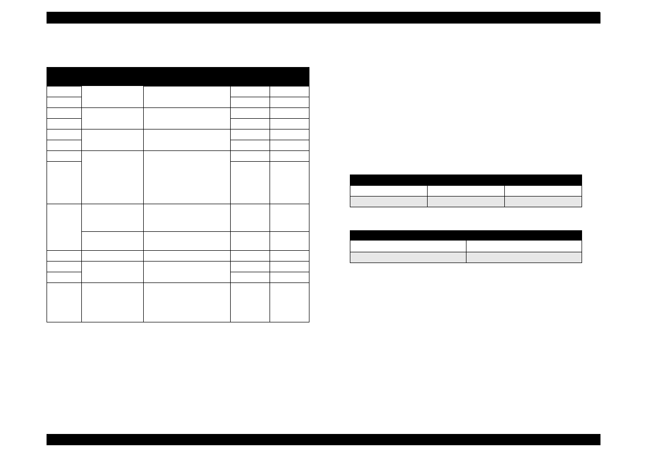
EPSON Stylus Color 440/640/740
Revision A
Chapter 7
Appendix
173
Notes:
**: Change model name of IEEE1284 device ID
*1.Adjusted at factory.
*2.Initialized after panel initialization is performed.
*3.01H is a factory setting for pacific market. (This note for the address 35H is only
applicable for the Stylus Color 440.)
*4.This function uses in the case that Raster graphics of 180 x 180 dpi (It is “economy”
binding in a driver.) is printed and specifies the size of a dot.
An ink life can be improved, by making this binding a normal x 1 dot, although an
ordinariness prints it with normal x2 dot. Yet, the printing result becomes pale even
since before. This function is implemented in the firmware subsequent to version
Kaxxxx. Refer to the tables below.
Table A-26.
Stylus Color 440/640
EEPROM Address Map (Continued)
Address
Explanation
Setting
QPIT
Settings
Factory
Settings
66H
Ink counter A
00H
00H
∗
2
67H
00H
00H
∗
2
68H
power off time
00H
00H
∗
2
69H
00H
00H
∗
2
6AH
CL time
00H
00H
∗
2
6BH
00H
00H
∗
2
6CH
accumulated
printing time
0: 0 minute
1: 15 minutes
2: 30 minutes
3: 60 minutes
4: 90 minutes
5: 120 minutes
00H
00H
6DH
00H
00H
6EH
Stylus Color 440
Dot size for
Economy mode
0: Normal x2 dot
1: Normal x1 dot
00H
00H
(*4)
Stylus Color 640
Reserved
00H
-
6FH
Reserved
00H
-
70H
Password 7
5AH
-
71H
0FH
-
72H to
79H,
7AH to
7FH
customized model
name
string of counter
strings of model field for
Device ID
00H
00H
Table A-27. Economy Mode Specifications
Normal x2 dot
Normal x1 dot
Ink life
the same as before
improved
color
the same as before
becomes pale
Table A-28. EEPROM Value and Dot Size
Value of EEPROM (6EH)
Dot Size
00H
Normal x2 dot
01H
Normal x1 dot
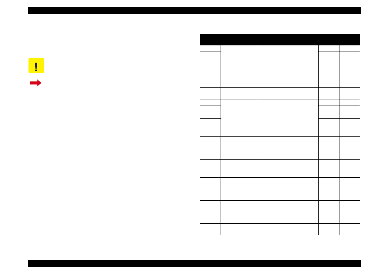
EPSON Stylus Color 440/640/740
Revision A
Chapter 7
Appendix
174
A.2.2 EEPROM Address Map
(Stylus Color 740)
This section provides EEPROM address map for the Stylus Color 740.
l
C A U T I O N
EEPROM map in this section only applies to Stylus
Color 740.
If you need EEPROM map for Stylus Color 440/640,
return to Section A.2.1. (They are combined in one
table.)
Table A-29.
Stylus Color 740
EEPROM Address Map
Address
Explanation
Setting
QPIT
Settings
Factory
Settings
00H
Password 0
0FH
-
01H
5AH
-
02H
EEPROM
mapping revision
41H
-
03H
Board lD
0: On-board RAM is 8 Mbit
1: On-board RAM is 16 Mbit
00H
(*1)
04H
CG
0: STD, 1: NLSP
00H
(*1)
05H
Market lD
0: Standard (World)
2: Custom
00H
(*1)
06H
Custom EEPROM
sub number
00H
00H
07H
00H
00H
08H
00H
00H
09H
00H
00H
0AH
Head actuator
rank lD for VhN
00H
(*1)
0BH
Head actuator
rank ID for Vh
µ
00H
(*1)
0CH
Head actuator
rank ID for VhL
00H
(*1)
0DH
Head actuator
rank lD for AR
00H
(*1)
0EH
Head rank MW-ID
00H
(*1)
0FH
Reserved for
Head-lD
00H
-
10H
Reserved for
Head-lD
00H
-
11H
Reserved for
Head-ID
00H
-
12H
Head actuator
rank lD for lwAB
00H
(*1)
13H
Head actuator
rank lD for lwCD
00H
(*1)
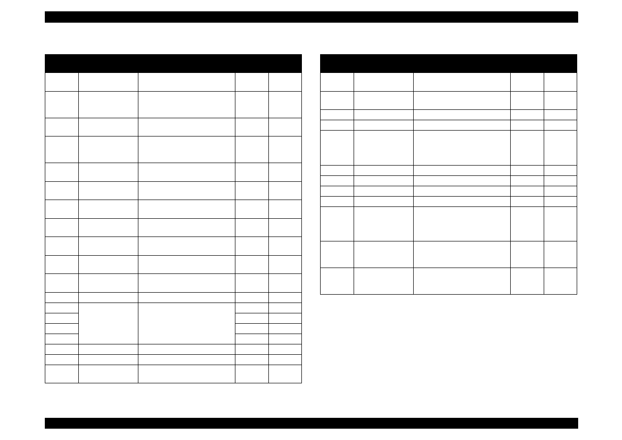
EPSON Stylus Color 440/640/740
Revision A
Chapter 7
Appendix
175
Table A-30.
Stylus Color 740
EEPROM Address Map (Coutinued)
Address
Explanation
Setting
QPIT
Settings
Factory
Settings
14H
Head actuator
rank ID for lwEF
00H
(*1)
15H
Bi-D Adjustment
data for Normal-
dot
-36<=n=<+36
(by 1/1440 inch)
00H
(*1)
16H
Bi-D Adjustment
data for Micro-dot
-36<=n=<+36
(by 1/1440 inch)
00H
(*1)
17H
Bi-D Adjustment
data for Variable-
dot
-36<=n=<+36
(by 1/1440 inch)
00H
(*1)
18H
Uni-D adjustment
data
-36<=n=<+36
(by 1/1440 inch)
00H
(*1)
19H
Reserved for
adjustment data
00H
-
1AH
Reserved for
adjustment data.
00H
-
1BH
1st dot position
adjustment data
-40<=n=<+40
(by 1/1440 inch)
00H
(*1)
1CH
Carriage speed
adjustment data
-4<=n<=+4
(by G.A. timer unit)
00H
(*1)
1DH
Carriage phase
on Home
00H
-
1EH
Paper sensor
adjustment data
-127<=n<=+127
(by 1/720 inch)
00H
(*1)
1FH
ERROR Code
00H
00H
20H
CPSl password
00H
00H
21H
00H
00H
22H
00H
00H
23H
00H
00H
24H
CPSI license flag
0: disable 1: enable
00H
00H
25H
CPSl font license
0: disable 1: enable
00H
00H
26H
Interface selection 0: Auto, 1: Parallel
2: Serial, 3: USB
00H
00H
(*2)
Table A-31.
Stylus Color 740
EEPROM Address Map (Coutinued)
Address
Explanation
Setting
QPIT
Settings
Factory
Settings
27H
Interface time-out
0 to 255 (by second, value of 0
means 10 seconds)
0AH
0AH
28H Compatibility
speed
0: Fast, 1: Slow
2: Special-1, 3: Special-2
00H
00H
29H
ECP speed *
3
0: Fast, 1: Slow
00H
00H
2AH
00H
00H
2BH
I/F Control flags
bit 1: ECP mode
(0=Off, 1=On) *
4
bit 0: IEEE1284 mode
(0=On, 1=Off) *
5
00H
00H
2CH
00H
01H
2DH
Reserved for USB
00H
-
2EH
Reserved for USB
00H
-
2FH
Reserved for USB
00H
-
30H
Font
0: Roman, 1: Sans Serif
2: Courier, 3: Prestige
4: Script, 10: Roman T
11: Sans Serif, 7: Draft
00H
02H
31H
Pitch
0: 10 cpi, 1: 12 cpi
2: 15 cpi, 3: 17 cpi
4: 20 cpi, 5: Proportional
00H
00H
32H
Print direction
control
0: Bi-D
1: Uni-D
2: Auto
02H
02H
*3: BUSY signal delay time form fall-edge of a -STB signal.
(Fast: Maximum 1MB/s, Slow: Maximum 600KB/s
*4: Select IEEE1284 transfer mode. (ECP or Nibble)
*5: Enable or disable reverse transfer. (When disabled, ignore -SLIN signal
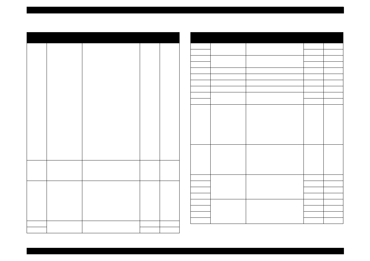
EPSON Stylus Color 440/640/740
Revision A
Chapter 7
Appendix
176
Table A-32.
Stylus Color 740
EEPROM Address Map (Coutinued)
Address
Explanation
Setting
QPIT
Settings
Factory
Settings
33H
CG table
0: Italic U.S.A., 1: Italic France,
2: Italic Germany 3: Italic U.K,
4: Italic Denmark, 5: Italic
Sweden, 6: Italic Italy, 7: Italic
Spain, 8: PC437, 9: PC437
Greek, 10: PC850, 11: PC860,
12: PC863, 13: PC865,
14: PC861, 15: BRASClI,
16: Abicomp, 17: Roman 8,
18: lSO Latin1, 19: PC853,
20: PC855, 21: PC852,
22: PC857, 23: PC866,
24: PC869, 25: MAZOWIA,
26: Code MJK,
27: ISO8859-7,
28: lSO Latin 1T,
29: Bulgaria, 30: PC774,
31: Estonia, 32: ISO 8859-2,
33: PC 866 LAT,
34: PC 866 UKR,
35: PC AR864,
36: PC APTEC, 37: PC 708,
38: PC720, 39: Hebrew7,
40: Hebrew8, 41: PC862
08H
08H
34H
Auto LF, Network
I/F mode
bit1: Network I/F mode
(0=0ff, 1=On),
bit0: Auto line feed
(0=Off, 1=On)
00H
00H
35H
Panel mask
function
bit 7: Entry Self-Test
bit 6: Entry Hex-Dump
bit 5: Extended settings
bit 4: Reserved
bit 3: Reserved
bit 2: Cleaning
bit 1: Replace I/C
bit 0: Load/Eject
00H
00H
36H
Top margin
42 to 44x360
(by 1/360 inch)
00H
00H
37H
78H
78H
Table A-33.
Stylus Color 740
EEPROM Address Map (Coutinued)
Address
Explanation
Setting
QPIT
Settings
Factory
Settings
38H
Bottom margin
1244 to 44x360
(by 1/360 inch)
IEH
IEH
39H
F0H
F0H
3AH
Page length
1244 to 44x360
(by 1/360 inch)
IEH
IEH
3BH
F0H
F0H
3CH
Reserved for main
00H
-
3DH
Reserved for main
00H
-
3EH
Reserved for main
00H
-
3FH
Reserved for main
00H
-
40H
Password 1
0FH
-
41H
5AH
-
42H
Ink flag 1
bit 7: Reserved
bit 6: black one-time
bit 5: color one-time
bit 4: Initial fill required
bit 3: Reserved
bit 2: ink cleaning seq.
Bit 1: black CL required
bit 0: color CL required
00H
00H
43H
Ink flag 2
bit 2: YMC cartridge
changed and cleaned
bit 1: Black cartridge
changed and cleaned
bit 0: Black cartridge
changed and cleaned
00H
00H
44H
Ink counter Cb
00H
00H
45H
00H
00H
46H
00H
00H
47H
00H
00H
48H
Ink counter Cy
00H
00H
49H
00H
00H
4AH
00H
00H
4BH
00H
00H
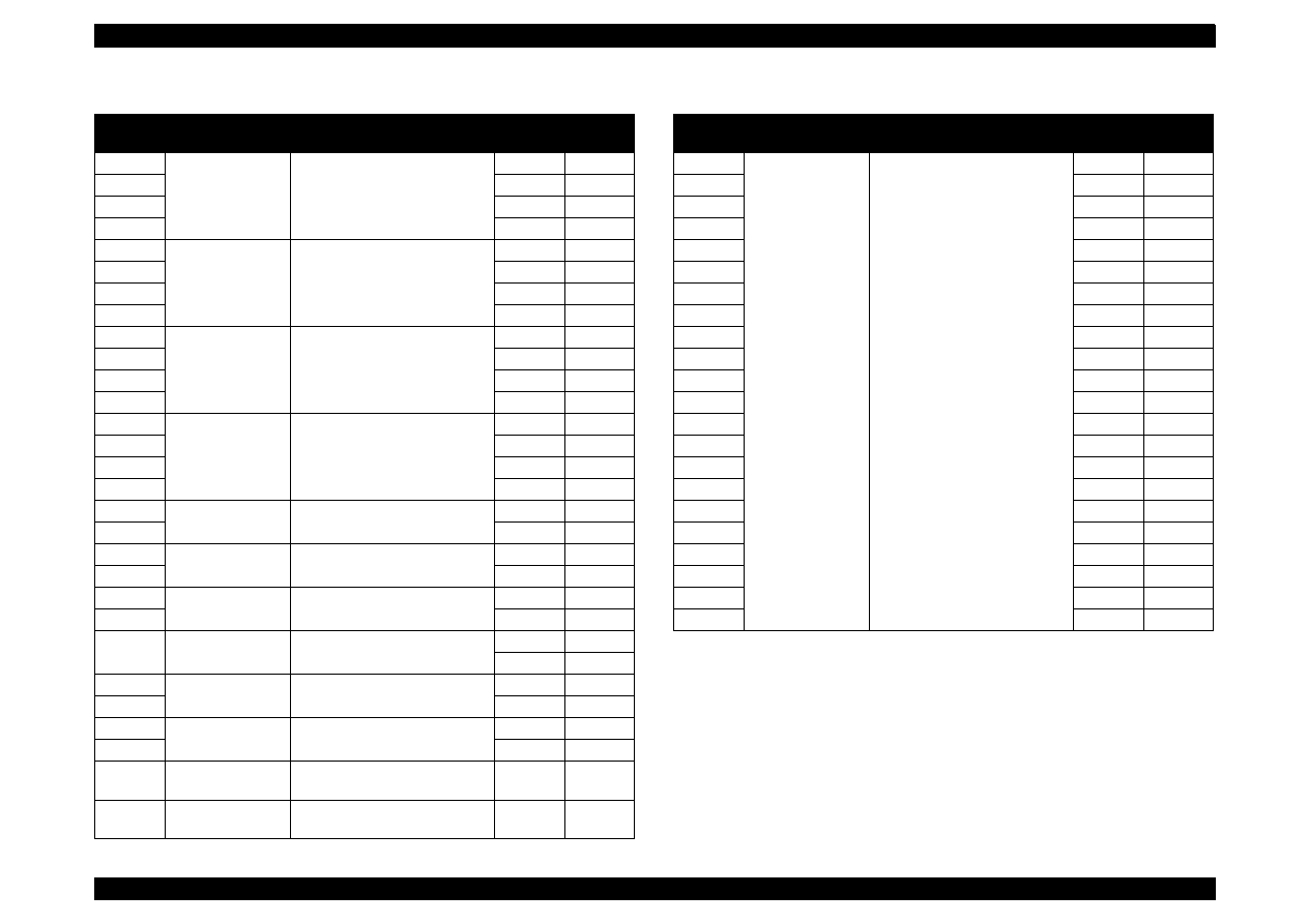
EPSON Stylus Color 440/640/740
Revision A
Chapter 7
Appendix
177
Table A-34.
Stylus Color 740
EEPROM Address Map (Coutinued)
Address
Explanation
Setting
QPIT
Settings
Factory
Settings
4CH
Ink counter Cm
00H
00H
4DH
00H
00H
4EH
00H
00H
4FH
00H
00H
50H
Ink counter Cc
00H
00H
51H
00H
00H
52H
00H
00H
53H
00H
00H
54H
Ink counter Clm
00H
00H
55H
00H
00H
56H
00H
00H
57H
00H
00H
58H
Ink counter Clc
00H
00H
59H
00H
00H
5AH
00H
00H
5BH
00H
00H
5CH
Ink counter Rb
00H
00H
5DH
00H
00H
5EH
Ink counter Ry
00H
00H
5FH
00H
00H
60H
Ink counter A
00H
00H(*2)
61H
00H
00H(*2)
62H
Power off time
00H
00H(*2)
63H
00H
00H(*2)
64H
CL time
00H
00H(*2)
65H
00H
00H(*2)
66H
accumulated
printing time
00H
00H
67H
00H
00H
68H
Reserved for ink
system
00H
-
69H
Reserved for ink
system
00H
-
Table A-35.
Stylus Color 740
EEPROM Address Map (Coutinued)
Address
Explanation
Setting
QPIT
Settings
Factory
Settings
6AH
Printer-ID Strings
[22]
00H
00H
6BH
00H
00H
6CH
00H
00H
6DH
00H
00H
6EH
00H
00H
6FH
00H
00H
70H
00H
00H
71H
00H
00H
72H
00H
00H
73H
00H
00H
74H
00H
00H
75H
00H
00H
76H
00H
00H
77H
00H
00H
78H
00H
00H
79H
00H
00H
7AH
00H
00H
7BH
00H
00H
7CH
00H
00H
7DH
00H
00H
7EH
00H
00H
7FH
00H
00H
*1:
Adjusted at factory
*2:
Initialized after panel initialization of EEPROM is performed.
*3: BUSY signal delay time form fall-edge of a -STB signal.
(Fast: Maximum 1MB/s, Slow: Maximum 600KB/s
*4: Select IEEE1284 transfer mode. (ECP or Nibble)
*5: Enable or disable reverse transfer. (When disabled, ignore -SLIN signal

EPSON Stylus Color 440/640/740
Revision A
Chapter 7
Appendix
178
A.3 Circuit Board Component Layouts
This section is composed of the following components layouts.
C206PSB/PSE (Stylus Color 440/640)
C257PSB/PSE (Stylus Color 740)
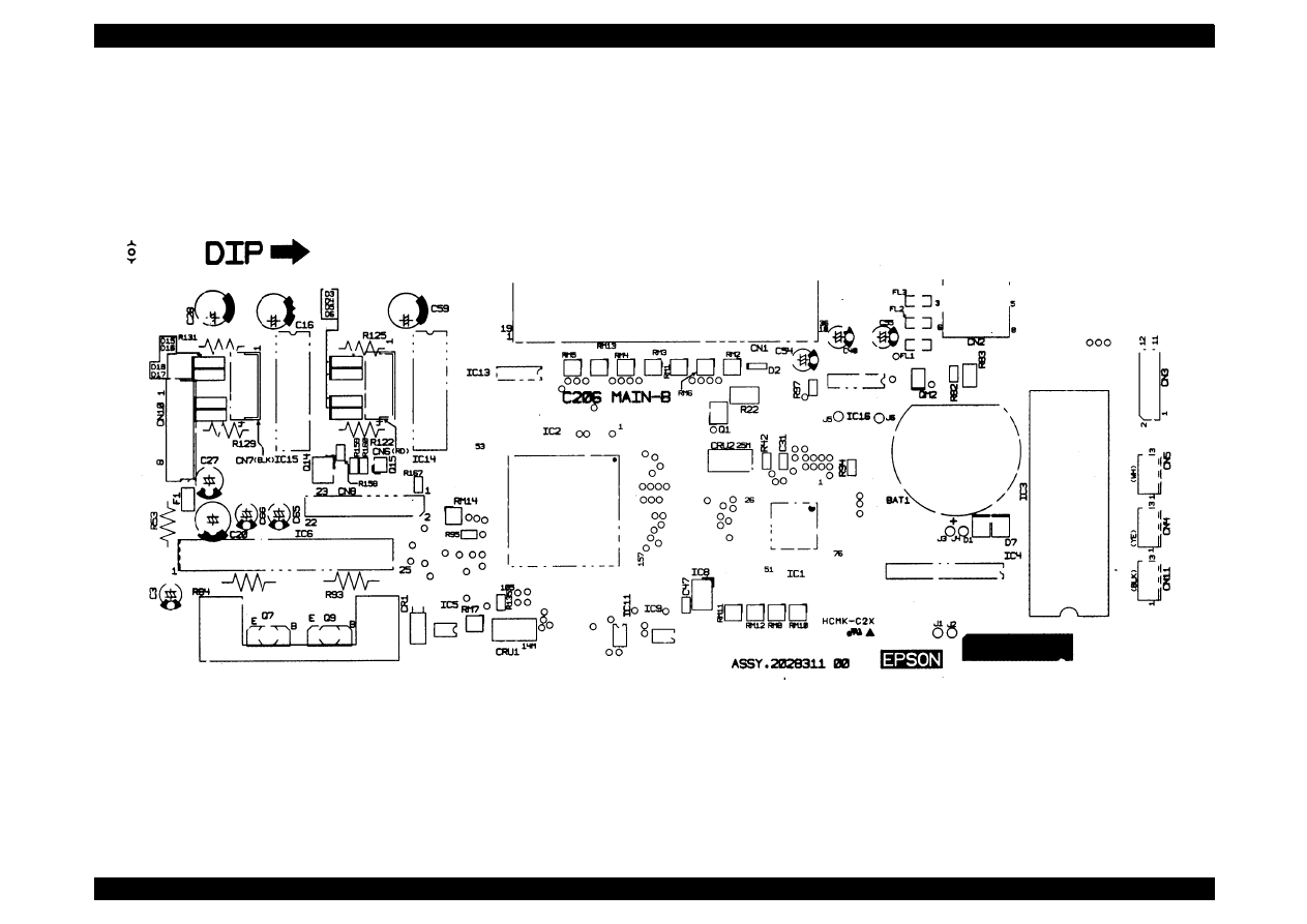
EPSON Stylus Color 440/640/740
Revision A
Chapter 7
Appendix
179
Figure A-3. C206MAIN-B Board Component Layout (1/2) (Stylus Color 440)
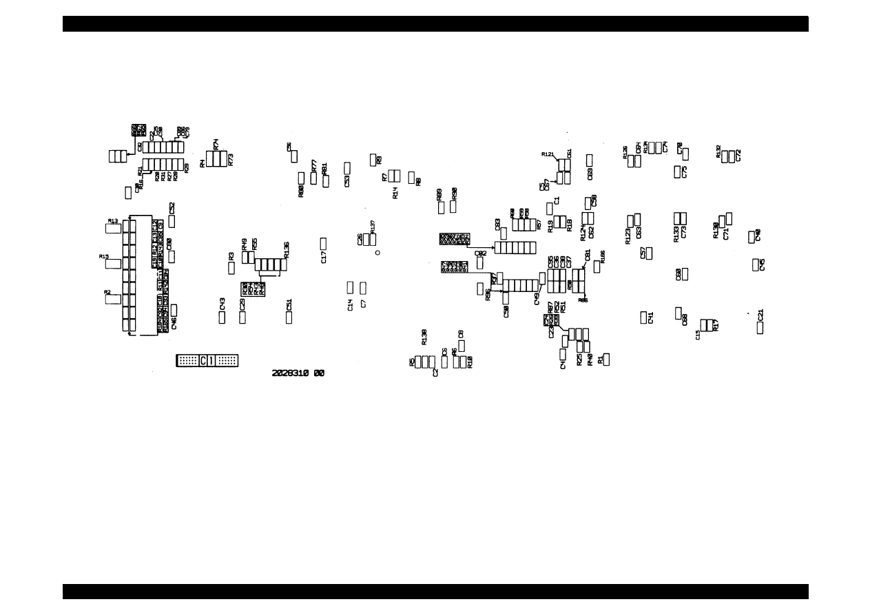
EPSON Stylus Color 440/640/740
Revision A
Chapter 7
Appendix
180
.
Figure A-4. C206MAIN-B Board Component Layout (2/2) (Stylus Color 440)
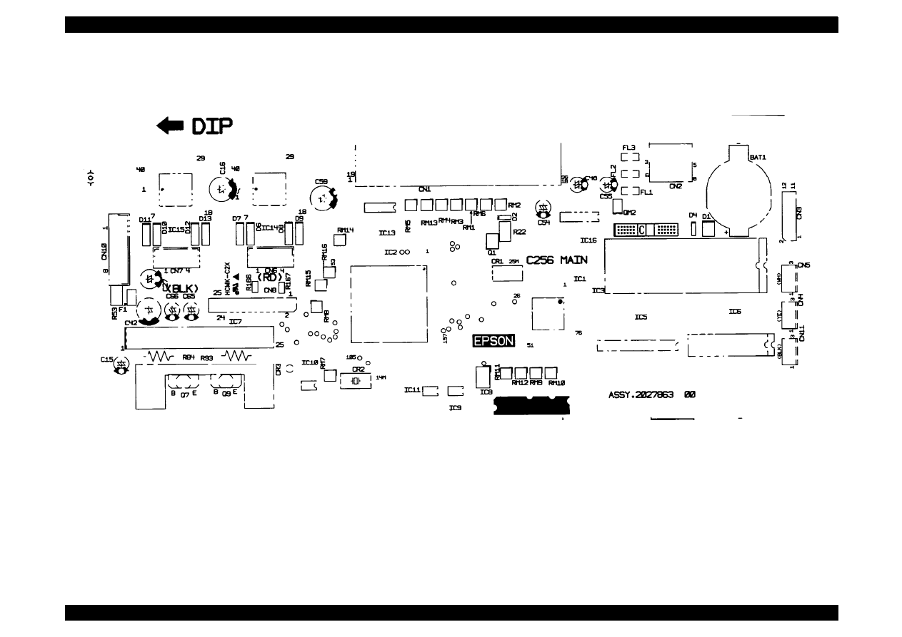
EPSON Stylus Color 440/640/740
Revision A
Chapter 7
Appendix
181
Figure A-5. C256MAIN Board Component Layout (1/2) (Stylus Color 640)
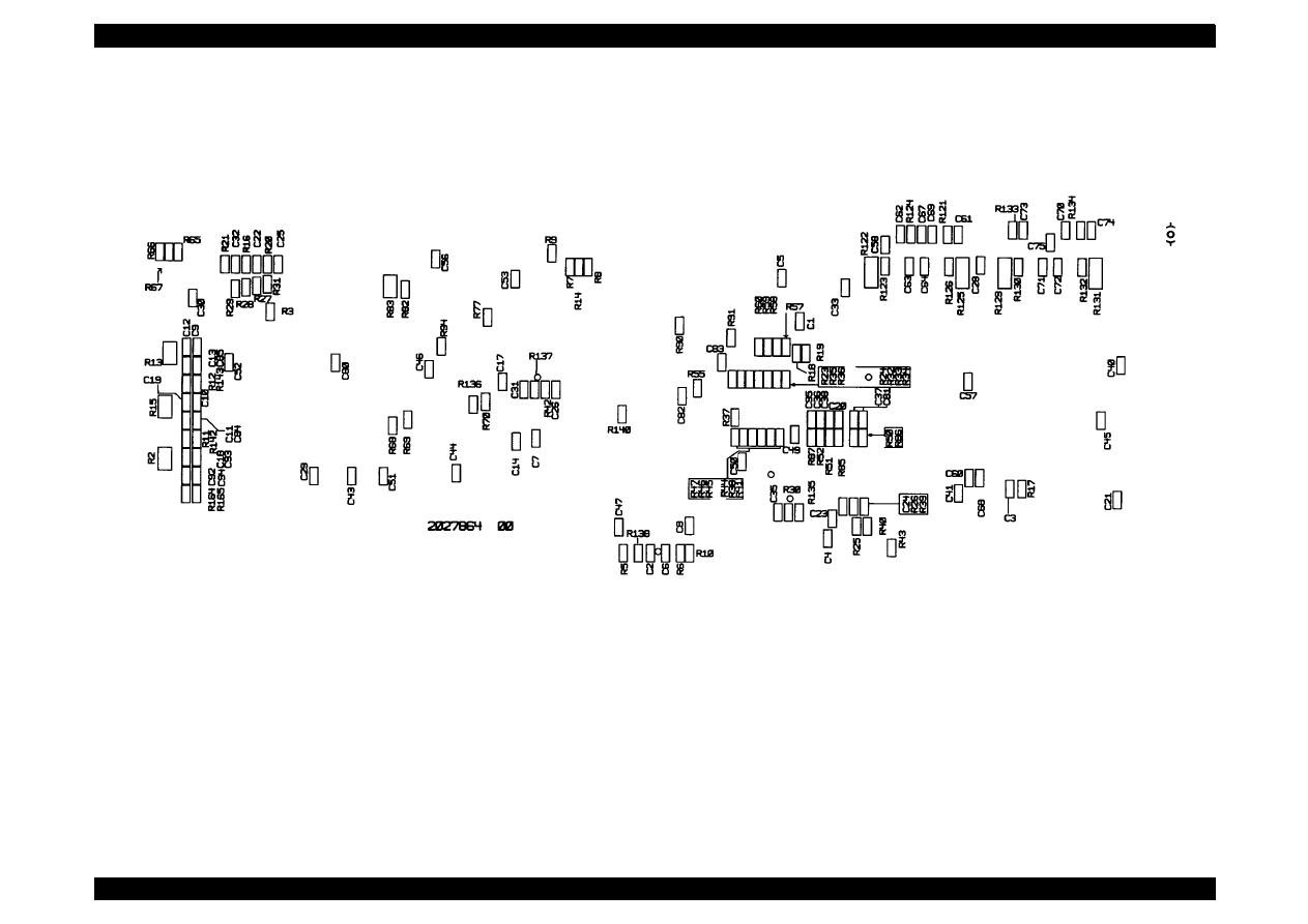
EPSON Stylus Color 440/640/740
Revision A
Chapter 7
Appendix
182
Figure A-6. C256MAIN Board Component Layout (2/2) (Stylus Color 640)
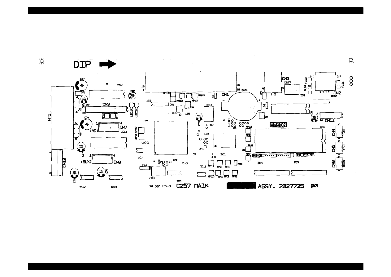
EPSON Stylus Color 440/640/740
Revision A
Chapter 7
Appendix
183
Figure A-7. C257MAIN Board Component Layout (1/2) (Stylus Color 740)
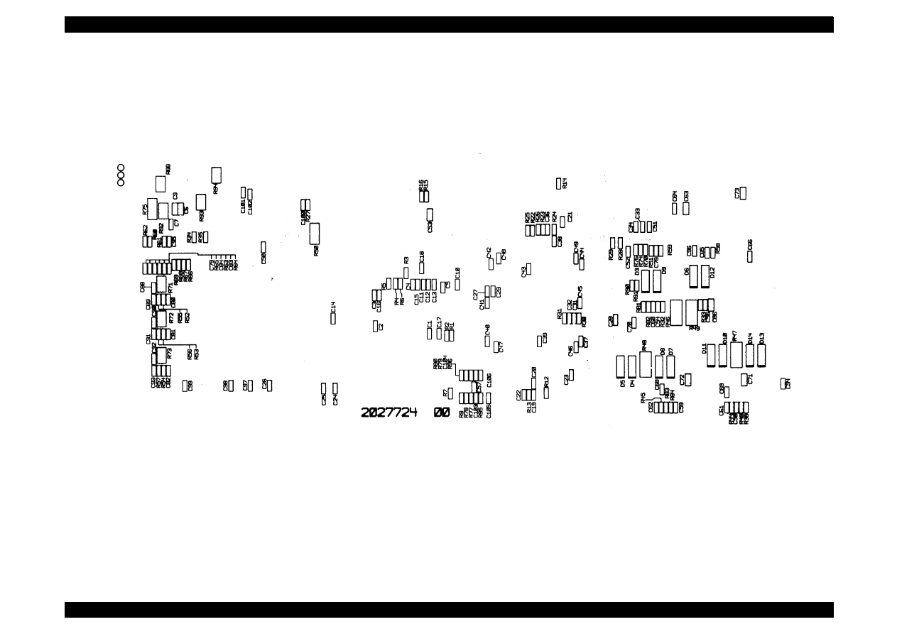
EPSON Stylus Color 440/640/740
Revision A
Chapter 7
Appendix
184
Figure A-8. C257MAIN Board Component Layout (2/2) (Stylus Color 740)
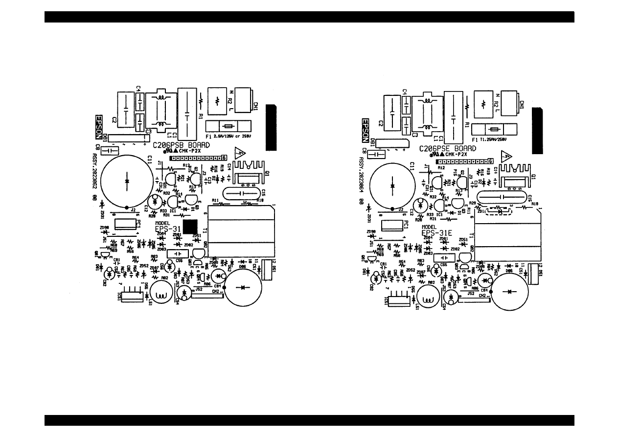
EPSON Stylus Color 440/640/740
Revision A
Chapter 7
Appendix
185
Figure A-9.
C206PSB Board Component Layout (Stylus Color 440/640)
Figure A-10.
C206PSE Board Component Layout (Stylus Color 440/640)
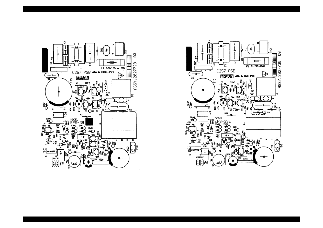
EPSON Stylus Color 440/640/740
Revision A
Chapter 7
Appendix
186
Figure A-11.
C257 PSB Board Component Layout (Stylus Color 740)
Figure A-12.
C257 PSE Board Component Layout (Stylus Color 740)
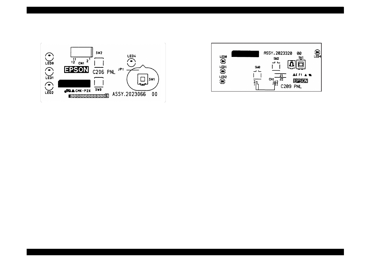
EPSON Stylus Color 440/640/740
Revision A
Chapter 7
Appendix
187
Figure A-13. C206PNL Component Layout
Figure A-14. C209PNL Component Layout

EPSON Stylus Color 440/640/740
Revision B
Chapter 7
Appendix
188
A.4 Exploded Diagrams
This section contains the following exploded diagrams.
Exploded diagram for Stylus Color 440 (1/3, 2/3, 3/3)
Exploded diagram for Stylus Color 640 (1/3, 2/3, 3/3)
Exploded diagram for Stylus Color 740 (1/3, 2/3, 3/3)
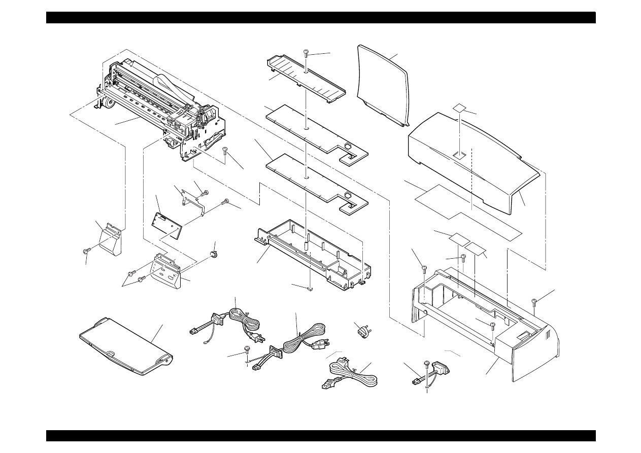
EPSON Stylus Color 440/640/740
Revision A
Chapter 7
Appendix
189
100
124
101
115
126
751
752
752
119
753
500
126
125
125
105
450
107
104
122
122
106
124
180
182
for LATIN
124
124
EXPLODED DIAGRAM FOR EPSON STYLUS COLOR 440 (1/3)
103
400
123
400
for EAI
400
for ETT
401
for EUR,S.E.ASIA,OCEANIA,EKL,RUSSIA
REV.1.0
10001
410
for RUSSIA
102
181
for LATIN

EPSON Stylus Color 440/640/740
Revision A
Chapter 7
Appendix
190
B
B
C
A
C
A
D
586
501
502
587
503
750
587
504
725
724
732
734
733
731
724
745
746
746
742
741
720
729
723
736
737
738
735
739
728
718
726
727
709
764
712
711
707
713
708
714
703
703
710
736
739
748
737
744
740
747
763
721
720
735
722
723
719
718
716
717
565
506
587
558
587
556
587
557
758
756
757
559
587
505
122
116
108
108
114
109
121
112
122
110
109
122
579
580
581
330
510
128
511
122
122
122
200
122
122
122
122
587
122
300
111
111
113
121
587
569
568
721
755
743
730
534
530
587
532
574
578
573
754
590
EXPLODED DIAGRAM FOR EPSON STYLUS COLOR 440 (2/3)
REV.1.0
10001
577
122
567
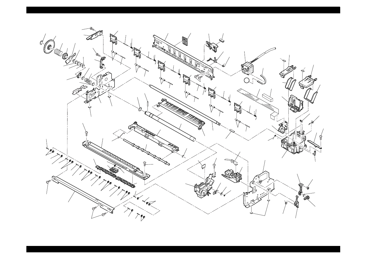
EPSON Stylus Color 440/640/740
Revision A
Chapter 7
Appendix
191
D
527
524
523
527
521
545
548
551
545
548
(506)
546
553
552
554
555
507
759
706
700
705
702
560
119
576
587
765
509
508
530
533
534
(505)
572
570
571
589
588
514
561
564 562
701
703
704
760
762
(565)
551
545
548
551
545
548
551
545
587
548
551
547
548
551
119
(501)
119
521
526
550
550
549
549
550
549
550
549
550
549
566
515
516
535
531
536
529
587
544
543
541
540
539
544
544
542
542
544
542
544
544
542
542
544
542
544
542 544
542
544
587
512
587
542 544
542
544
542 544
542
544
542
538
587
527
522
563
550
549
122
117
588
513
518
528
525
528
517
519
520
EXPLODED DIAGRAM FOR EPSON STYLUS COLOR 440 (3/3)
REV.1.0
10001
183
184
761
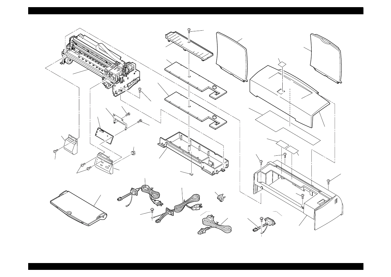
EPSON Stylus Color 440/640/740
Revision A
Chapter 7
Appendix
192
REV.1.0
10002
103
400
123
400
for EAI
400
for ETT
100
124
101
115
126
751
752
752
119
753
500
126
125
125
105
450
107
122
122
106
124
180
182
for LATIN
124
124
401
EXPLODED DIAGRAM FOR EPSON STYLUS COLOR 640 (1/3)
for EUR,S.E.ASIA,OCEANIA,EKL,RUSSIA
410
for RUSSIA
102
for USA
102
for EUR.,S.E.ASIA,OCEANIA
EKL,RUSSIA
104
181
for LATIN

EPSON Stylus Color 440/640/740
Revision A
Chapter 7
Appendix
193
B
B
C
A
C
A
D
586
501
502
587
503
750
587
504
725
724
732
734
733
731
724
745
746
746
742
741
720
729
723
736
737
738
735
739
728
718
726
727
709
764
712
711
707
713
708
714
703
703
710
736
739
748
737
744
740
747
763
721
720
735
722
723
719
718
716
717
565
506
587
558
587
556
587
557
758
756
757
559
587
505
122
116
108
108
114
109
121
112
122
110
109
122
579
580
581
330
510
128
511
122
122
122
200
122
122
122
122
587
122
300
111
111
113
121
587
569
568
721
755
743
730
534
530
587
532
574
578
573
754
590
EXPLODED DIAGRAM FOR EPSON STYLUS COLOR 640 (2/3)
REV.1.0
10002
577
122
567
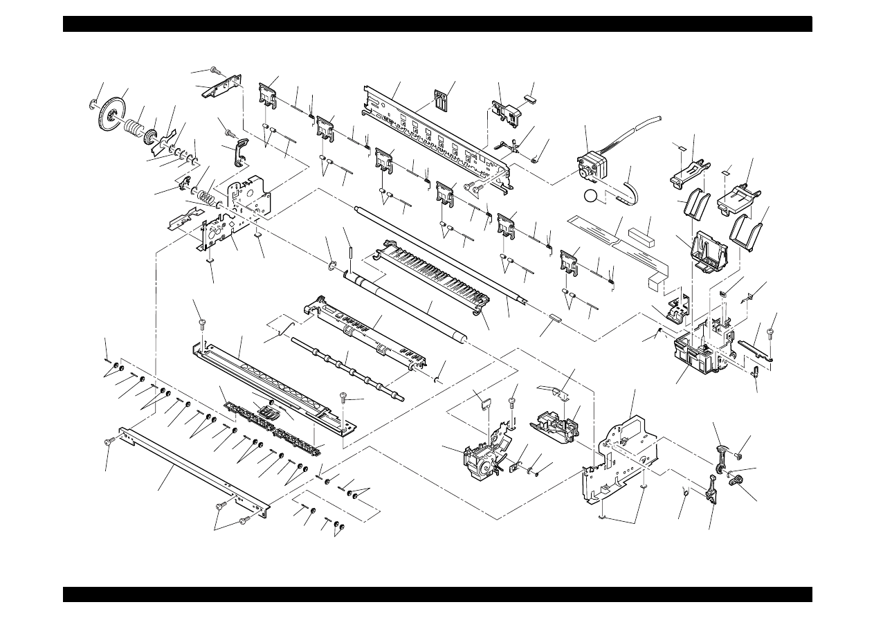
EPSON Stylus Color 440/640/740
Revision A
Chapter 7
Appendix
194
D
527
524
523
527
521
545
548
551
545
548
(506)
546
553
552
554
555
507
759
706
700
705
702
560
119
576
587
765
509
508
530
533
534
(505)
572
570
571
589
588
514
561
564 562
701
703
704
760
761
762
(565)
551
545
548
551
545
548
551
545
587
548
551
547
548
551
119
(501)
119
521
526
550
550
549
549
550
549
550
549
550
549
566
515
516
535
531
536
529
587
544
543
541
540
539
544
544
542
542
544
542
544
544
542
542
544
542
544
542 544
542
544
587
512
587
542 544
542
544
542 544
542
544
542
538
587
527
522
563
550
549
122
117
588
513
518
528
525
528
517
519
520
EXPLODED DIAGRAM FOR EPSON STYLUS COLOR 640 (3/3)
REV.1.0
10002
184
183
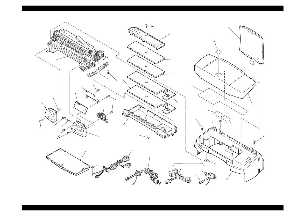
EPSON Stylus Color 440/640/740
Revision B
Chapter 7
Appendix
195
103
400
123
400
for EAI
400
for ETT
100
124
101
102
115
126
751
752
766
766
752
119
753
500
126
125
125
125
105
450
107
104
122
122
135
106
132
133
124
181
for EAI,
LATIN
180
182
for LATIN
124
124
401
134
EXPLODED DIAGRAM FOR EPSON STYLUS COLOR 740 (1/3)
Rev.01 10004
123
For EUR,S.E.ASIA,
OCEANIA,RUSSIA
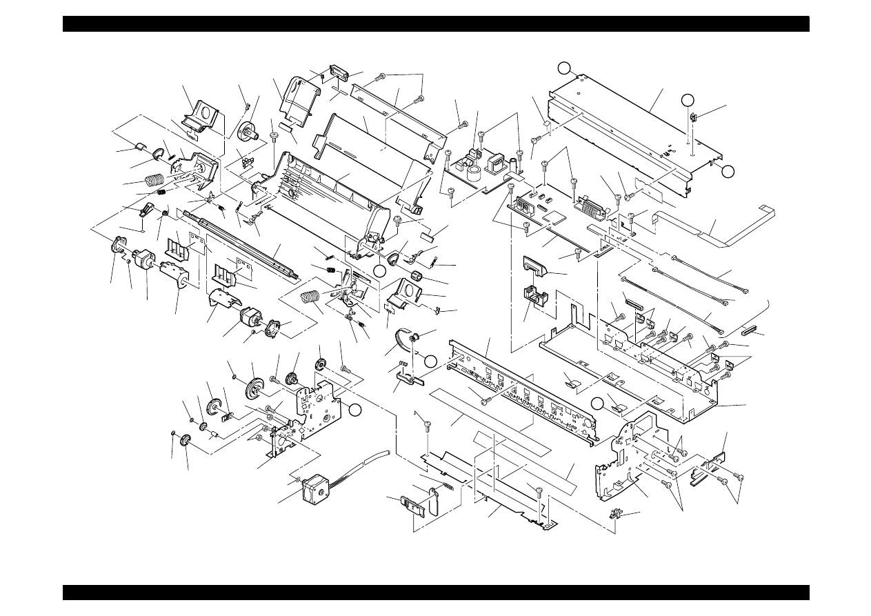
EPSON Stylus Color 440/640/740
Revision B
Chapter 7
Appendix
196
B
B
C
A
C
A
D
501
502
592
587
503
750
587
504
725
724
732
734
733
731
724
745
746
746
742
741
720
729
723
736
737
738
735
739
728
718
726
727
709
764
712
711
707
713
708
714
703
703
710
736
739
748
737
744
740
747
763
721
720
735
722
723
719
718
716
717
567
565
506
587
558
587
556
587
557
758
756
757
559
587
505
122
116
108
108
114
109
121
112
122
109
109
122
579
580
581
330
510
598
128
511
122
122
122
200
122
122
122
122
587
587
122
300
111
131
113
121
587
569
568
721
755
743
730
534
530
587
591
591
532
574
578
573
590
EXPLODED DIAGRAM FOR EPSON STYLUS COLOR 740 (2/3)
577
Rev.01 10004
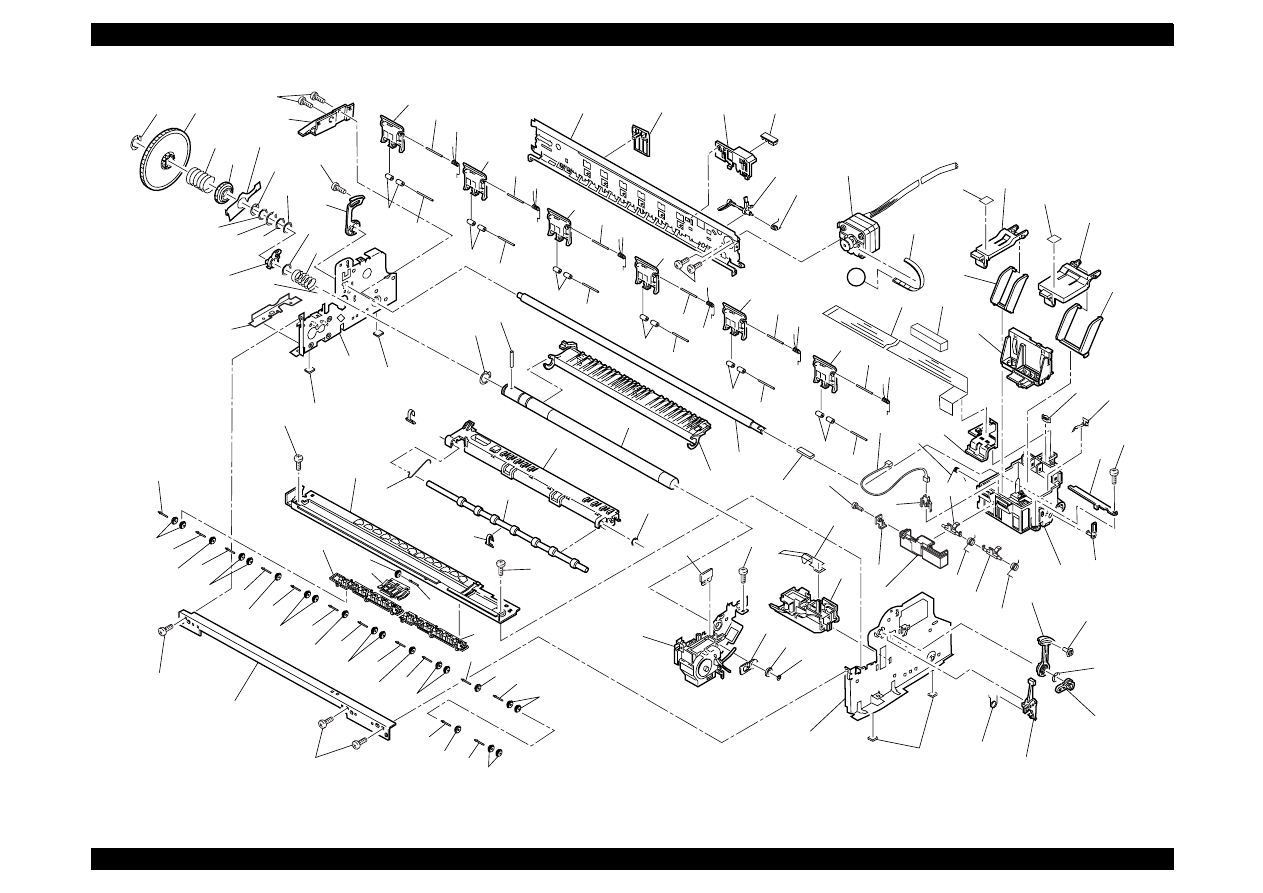
EPSON Stylus Color 440/640/740
Revision B
Chapter 7
Appendix
197
D
527
524
523
527
521
545
548
551
545
548
(506)
546
553
552
554
555
507
759
183
184
706
700
705
702
560
595
596
600
601
767
602
597
600
768
119
576
587
765
509
508
530
533
534
(505)
572
570
571
589
588
514
561
564 562
701
703
704
760
761
762
(565)
551
545
548
551
545
548
551
545
587
548
551
547
548
551
119
(501)
119
521
526
550
550
549
549
550
549
550
549
550
549
566
515
516
535
531
536
529
587
544
543
541
540
539
544
544
542
542
544
542
544
544
542
542
544
542
544
542 544
542
544
587
512
587
542 544
542
544
542 544
542
544
542
538
587
527
522
563
550
549
122
117
588
513
518
528
525
528
517
519
520
EXPLODED DIAGRAM FOR EPSON STYLUS COLOR 740 (3/3)
754
Rev.01 10004
537
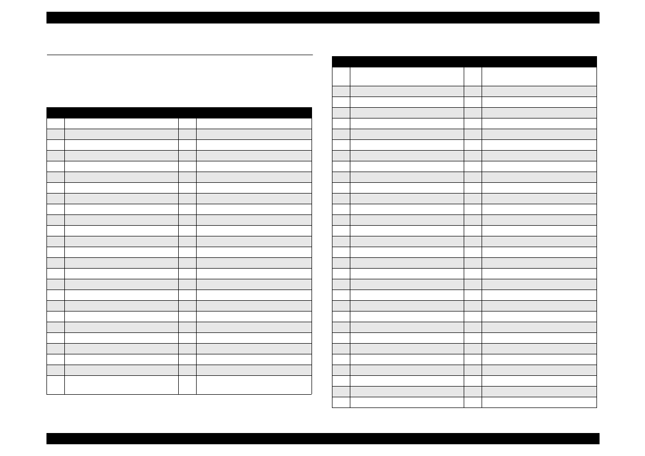
EPSON Stylus Color 440/640/740
Revision B
Chapter 7
Appendix
198
A.5 Part List
A.5.1
Part List
for Stylus Color 440/640
Table A-36. Part List for Stylus Color 440/640 (1/4)
Part Name
Part Name
100 Housing;B
128 Mini Clamp
101 Cover, Printer;B
180 Label, Caution 1;B
102 Paper Support;B
181 Label, Accessory B
103 Stacker Assembly;B
182 Label, Accessry C
104 Panel Assembly, Right;B
183 Label, Lever Cartridge, Black
105 Shield Plate, Panel
184 Label, Lever Cartridge, Color
106 Housing, Panel, Left;B
200 Board Assembly, Main
107 Button, P/S;B
300 Board Assembly, Power Supply
108 Groundign Plate
330 Harness
109 Cover, Shield Plate, M/B, Right
400 Power Cable Assembly
110 Cover, Shield Plate, M/B, Left
450 Board Assembly, Panel
111 Cover, Cable
500 Printer Mechanism
112 Cover, Inlet, Upper;B
501 Frame Assembly, Left
113 Cover, Inlet, Lower;B
502 Motor Assembly, PF
114 Shiled Plate, M/B;C
503 Spur Gear, 23.2
115 Logo Plate
504 Combination Gear, 16, 40.8
116 Housing, Sub, Right;B
505 Frame, Right
117 Housing Sub, Left;B
506 Frame, Top
119 Foot
507 Motor Assembly, CR
121 CP Screw, M3x6
508 Pump Assembly
122 CBS-Tite Screw, M3x6
509 Cap Assembly
123 CB(O) Screw, 4x5, F/Zg
510 Frame, Bottom
124 CBS-Tite Screw, M3x10
511 Sheet, Protection, Head
125 CBP-Tite Screw, M3x8, F/Zn
512 Frame, Front
126 CBP-Tite Screw, M3x10, F/Zn
513 Bushing, Parallelism Adjustment,
Left
Table A-37. Part List for Stylus Color 440/640 (2/4)
Part Name
Part Name
514 Bushing, Parallelism Adjustment,
Right
546 Paper Guide, Right
515 Paper Guide, Rear
547 Paper Guide, Left
516 Roller, PF
548 Shaft, Paper Guide, Upper
517 Compression Spring, 5.85
549 Shaft, Roller, Driven
518 Bushing, 12, Left
550 Roller, Driven;D
519 Lever, Change
551 Torsion Spring, 117.6
520 Spur Gear, 26.4
552 Board Assembly, PE
521 Spacer, C-ring
553 Holder, PE
522 Scallop Sp-AW, 2x16, F/B
554 Lever, PE
523 Compression Spring, 0.9
555 Torsion Spring, 0.22
524 Spur Gear, 67.2
556 Sheet, Guide Plate, Cable
525 Spacer, Fixing, Roller, PF
557 Guide Plate, Cable
526 Spacer, Fixing, Roller, PF;B
558 Sheet, Cable
527 Crescent Ring
559 Detector, PE
528 Plain Washer12.2x0.5x15
560 Carriage Assembly
529 Roller Assembly, Paper Eject
561 Lever, Adjust
530 Bushing, 6
562 Grouding Plate, Head
531 Retaining Ring, Type-E(4)
563 Oil Pad
532 Spur Gear, 36
564 Slider, CR
533 Spur Gear, 11
565 Timing Belt
534 Plain Washer, 4.1x0.5x6.5
566 Shaft, CR, Guide
535 Paper Guide, Front
567 Pulley Assembly, Driven
536 Grounding Spring, Paper Eject
568 Holder, Pulley, Driven
538 Frame, Paper Eject
569 Compression Spring, 19.6
539 Holder, Star Wheel, Right
570 Lever, PG
540 Holder, Star Wheel, Left
571 Lever, PG, Sub
541 Holder, Star Wheel, Front
572 Torsion Spring, 63.7
542 Star Wheel Assembly, 8(Natural)
573 Combination Spring, 6, 34.4
543 Star Wheel 8;B
574 Combination Spring, 8, 30
544 Bar Spring, Star Wheel
576 Absorber, Slider, Cap
545 Paper Guide, Upper
577 Bushing, Fixing, Combination Gear
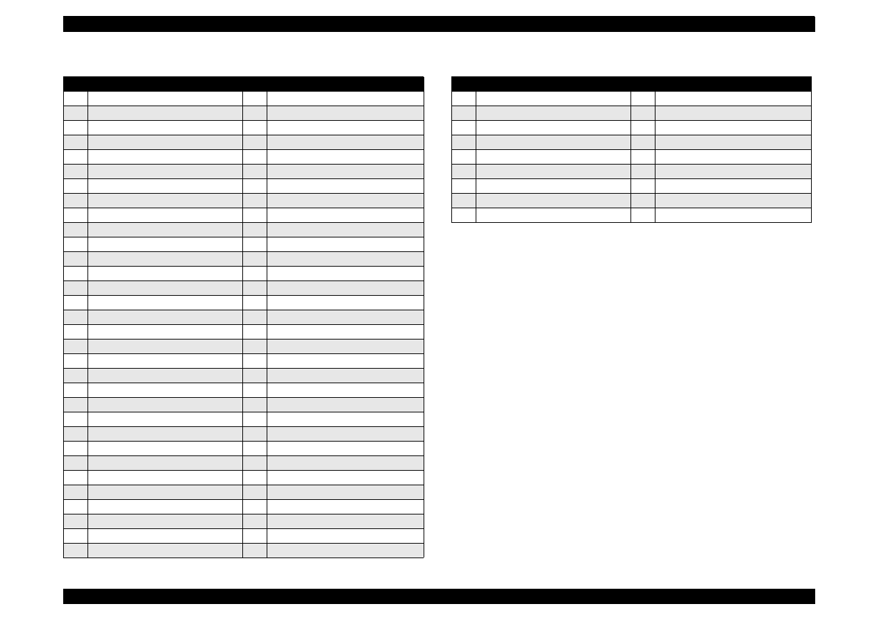
EPSON Stylus Color 440/640/740
Revision B
Chapter 7
Appendix
199
Table A-38. Part List for Stylus Color 440/640 (3/4)
Part Name
578 Push Nut, 2
724 Roller, LD, Sub
579 Harness, HP
725 Holder, Roller, LD, Sub, Right
580 Harness, PE
726 Pad Assy., Left
581 Harness, ASF
727 Lever, Pad, Release, Left
586 CBS-Tite Screw
728 Holder, Edge Guide, Left
587 CBS-Tite Screw, M3x6
729 Lever, Paper Return, Left
588 CBS-Tite (P4) Screw, 3x6, F/Zn
730 Holder, Roller, LD, Sub, Left
589 Leaf Spring, 6.2x0.15x11
731 Roller Assy., LD, Left
590 Plain Washer, 2.6x0.5x8
732 Roller Assy., LD, Right
700 Printehead
733 Cover, Roller, LD, Left
701 Fastener, Head
734 Cover, Roller, LD, Right
702 Torsion Spring, 49
735 Compression Spring, 1.961
703 CBP-Tite Screw, 3x6, F/Zn
736 Lever, Fixing, Edge Guide;B
704 Cable, Head
737 Tension Spring, 0.088
705 Holder, Cable
738 Shaft, Roller, LD
706 Spacer, Cable Head
739 Lever, Hopper, Release
707 Frame, ASF;B
740 Wheel, Detection
708 Hopper
741 Lever, Brake
709 Edge Guide
742 Pad, Brake
710 Cork
743 Torsion Spring, 41.2
711 Slider, Edge Guide
744 Bushing, Fixing, Shaft
712 Compression Spring, 3.23
745 Sheet, Paper Feed
713 Pad, Brake, Edge Guide
746 Holder, Sheet, Paper Feed
714 Reinforcing Plate, Hopper
747 Shaft, Mouting, CR
716 Pad Assy., Right
748 CBS (P4) Screw, 3x6, F/Zn
717 Lever, Pad, Release, Right
750 Spur Gear, 34
718 Bar Spring, Holder, Pad
751 Paper Guide, Lower
719 Holder, Edge Guide, Right
752 Absorber, Waste Ink, Large
720 Compression Spring, 1.17
753 Tray, Absorber
721 Tension Spring, 0.62
754 Spacer, Tray
722 Lever, Paper Return, Right
755 Bushing, Fixing, Shaft, Left
723 Tension Spring, 0.294
756 Paper Support, Sub, Upper
Table A-39. Part List for Stylus Color 440/640 (4/4)
757 Holder, Paper Support, Sub, Upper
758 Torsion Spring, 0.29
759 Cover, Cartridge, Bk
760 Cover, Cartridge, C;B
761 Separator, Cartridge, Bk
762 Separator, Cartridge, C
763 Detector, HP
764 Cork;B
765 Cleaner, Head, ASP
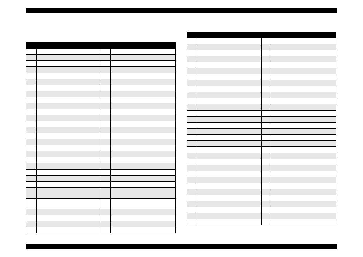
EPSON Stylus Color 440/640/740
Revision B
Chapter 7
Appendix
200
A.5.2
Part List
for Stylus Color 740
Table A-40. Part List for Stylus Color 740 (1/4)
100
Housing
135 Spacer, Housing, Panel
101
Cover, Printer
180 Label, Caution 1
102
Paper Support Assembly
181 Label, Accessory
103
Stacker Assembly
183 Label, Lever Cartridge, Black
104
Panel Assembly
184 Label, Lever Cartridge, Color
105
Shield Plate, Panel
200 Board Assembly, Main
106
Housing, Panel, Left
300 Board Assembly, Power Supply
107
Button, P/S;B
330 Harness
108
Groundign Plate
400 Power Cable Assembly
109
Cover, Shield Plate, M/B, Right
450 Board Assembly, Panel
111
Cover, Cable
500 Printer Mechanism
112
Cover, Inlet, Upper;B
501 Frame Assembly, Left
113
Cover, Inlet, Lower;B
502 Motor Assembly, PF
114
Shiled Plate, M/B
503 Spur Gear, 23.2
115
Logo Plate
504 Combination Gear, 16, 40.8
116
Housing, Sub, Right;B
505 Frame, Right
117
Housing Sub, Left;B
506 Frame, Top
119
Foot
507 Motor Assembly, CR
121
CP Screw, M3x6
508 Pump Assembly
122
CBS-Tite Screw, M3x6
509 Cap Assembly
123
CB(O) Screw, 4x5, F/Zg
510 Frame, Bottom
124
CBS-Tite Screw, M3x10
511 Sheet, Protection, Head
125
CBP-Tite Screw, M3x8, F/Zn
512 Frame, Front
126
CBP-Tite Screw, M3x10, F/Zn
513 Bushing, Parallelism Adjustment,
Left
128
Mini Clamp
514 Bushing, Parallelism Adjustment,
Right
131
Cover, Cable;B
515 Paper Guide, Rear
132
Lock, Stacker
516 Roller, PF
133
Compression Spring, 2.94
517 Compression Spring, 5.85
134
Spacer, Housing
518 Bushing, 12, Left
Table A-41. Part List for Stylus Color 740 (2/4)
519 Lever, Change
550
Roller, Driven;D
520 Spur Gear, 26.4
551
Torsion Spring, 117.6
521 Spacer, C-ring
552
Board Assembly, PE
522 Scallop Sp-AW, 2x16, F/B
553
Holder, PE
523 Compression Spring, 0.9
554
Lever, PE
524 Spur Gear, 73.6
555
Torsion Spring, 0.22
525 Spacer, Fixing, Roller, PF
556
Sheet, Guide Plate, Cable
526 Spacer, Fixing, Roller, PF;B
557
Guide Plate, Cable
527 Crescent Ring
558
Sheet, Cable
528 Plain Washer, 12.2x0.5x15
559
Detector, HP
529 Roller Assembly, Paper Eject
560
Carriage Assembly
530 Bushing, 6
561
Lever, Adjust
531 Retaining Ring, Type-E(4)
562
Grouding Plate, Head
532 Spur Gear, 36
563
Oil Pad
533 Spur Gear, 11
564
Slider, CR
534 Plain Washer, 4.1x0.5x6.5
565
Timing Belt
535 Paper Guide, Front
566
Shaft, CR, Guide
536 Grounding Spring, Paper Eject
567
Pulley Assembly, Driven
537 Guide, Paper Eject
568
Holder, Pulley, Driven;B
538 Frame, Paper Eject
569
Compression Spring, 19.6
539 Holder, Star Wheel, Right
570
Lever, PG
540 Holder, Star Wheel, Left
571
Lever, PG, Sub
541 Holder, Star Wheel, Front
572
Torsion Spring, 63.7
542 Star Wheel Assembly, 8(Natural)
573
Combination Spring, 12.4, 28
543 Star Wheel 8;B
574
Combination Spring, 16, 21.6
544 Bar Spring, Star Wheel
576
Absorber, Slider, Cap
545 Paper Guide, Upper
577
Bushing, Fixing, Combination Gear
546 Paper Guide, Right
578
Push Nut, 2
547 Paper Guide, Left
579
Harness, HP
548 Shaft, Paper Guide, Upper
580
Harness, PE
549 Shaft, Roller, Driven
581
Harness, ASF
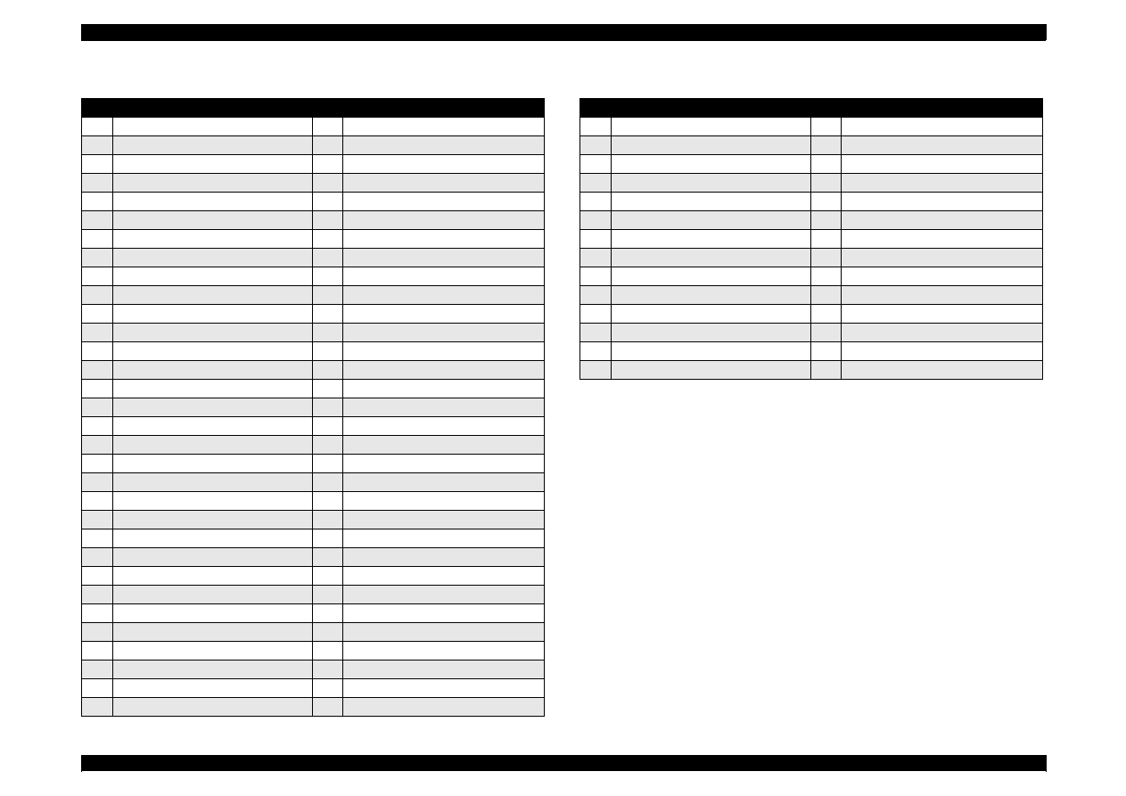
EPSON Stylus Color 440/640/740
Revision B
Chapter 7
Appendix
201
Table A-42. Part List for Stylus Color 740 (3/4)
586 CBS-Tite Screw
719 Holder, Edge Guide, Right
587 CBS-Tite Screw, M3x6
720 Compression Spring, 1.17
588 CBS-Tite (P4) Screw, 3x6, F/Zn
721 Tension Spring, 0.62
589 Leaf Spring, 6.2x0.15x11
722 Lever, Paper Return, Right
590 Plain Washer, 6.1x0.5x9.0
723 Tension Spring, 0.294
591 6N, Class 2, M3
724 Roller, LD, Sub
592 Plain Washer, 3x0.3x7
725 Holder, Roller, LD, Sub, Right
595 Holder, Detector, I/C
726 Pad Assy., Left
596 Lever, Detector, I/C, Bk
727 Lever, Pad, Release, Left
597 Lever, Detector, I/C, CL
728 Holder, Edge Guide, Left
598 Grounding Plate, Roller, PF
729 Lever, Paper Return, Left
600 Torsion Spring, 1.08
730 Holder, Roller, LD, Sub, Left
601 Detector, I/C
731 Roller Assy., LD, Left
602 Harness, I/C
732 Roller Assy., LD, Right
700 Printehead
733 Cover, Roller, LD, Left
701 Fastener, Head
734 Cover, Roller, LD, Right
702 Torsion Spring, 49
735 Compression Spring, 1.961
703 CBP-Tite Screw, 3x6, F/Zn
736 Lever, Fixing, Edge Guide;B
704 Cable, Head
737 Tension Spring, 0.088
705 Holder, Cable
738 Shaft, Roller, LD
706 Spacer, Cable Head
739 Lever, Hopper, Release
707 Frame, ASF;B
740 Wheel, Detection
708 Hopper
741 Lever, Brake
709 Edge Guide
742 Pad, Brake
710 Cork
743 Torsion Spring, 41.2
711 Slider, Edge Guide
744 Bushing, Fixing, Shaft
712 Compression Spring, 3.23
745 Sheet, Paper Feed
713 Pad, Brake, Edge Guide
746 Holder, Sheet, Paper Feed
714 Reinforcing Plate, Hopper
747 Shaft, Mouting, CR
716 Pad Assy., Right
748 CBS (P4) Screw, 3x6, F/Zn
717 Lever, Pad, Release, Right
750 Spur Gear, 34
718 Bar Spring, Holder, Pad
751 Paper Guide, Lower
Table A-43. Part Lis for Stylus Color 740 (4/4)
752 Absorber, Waste Ink, Large
753 Tray, Absorber
754 Spacer, Tray
755 Bushing, Fixing, Shaft, Left
756 Paper Support, Sub, Upper
757 Holder, Paper Support, Sub, Upper
758 Torsion Spring, 0.29
759 Cover, Cartridge, Bk
760 Cover, Cartridge, C;B
761 Separator, Cartridge, Bk
762 Separator, Cartridge, C
763 Detector, HP
764 Cork;B
765 Cleaner, Head, ASP

EPSON Stylus Color 440/640/740
Revision B
Chapter 7
Appendix
202
A.6 Circuit Diagrams
See the following pages for the circuit diagrams below.
NOTE: For circuit diagram for C206MAIN-B, refer to the hard
copies, as no pdf files for it is provided.
C206MAIN-B circuit diagram 1/2, 2/2
See the hard copies.

EPSON Stylus Color 440/640/740
Revision B
Chapter 7
Appendix
203
C206MAIN-B Circuit diagrams 1of 2
See the hard copy.

EPSON Stylus Color 440/640/740
Revision B
Chapter 7
Appendix
204
C206MAIN-B Circuit diagrams 2 of 2
See the hard copy.
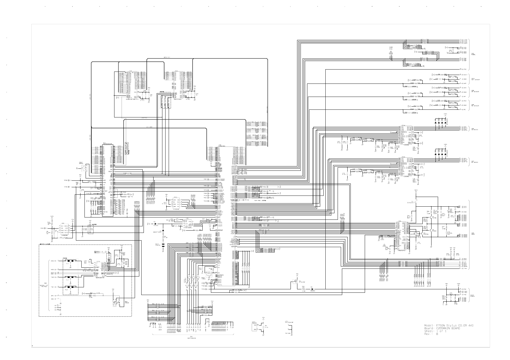
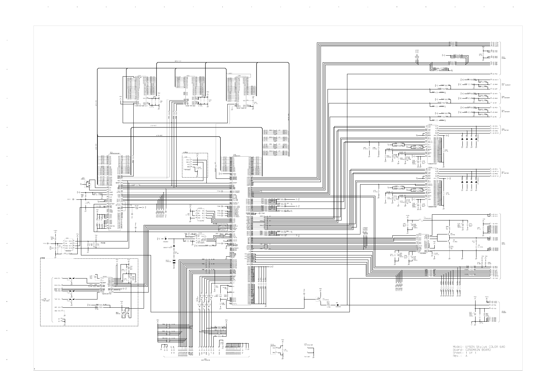
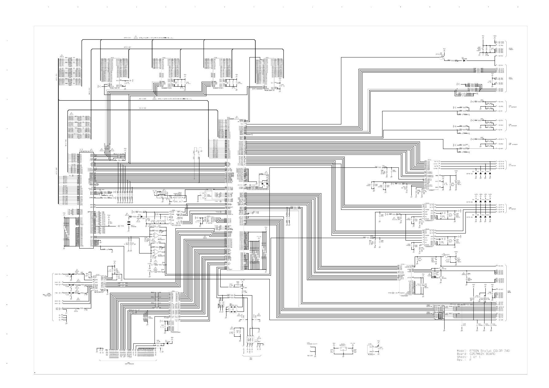
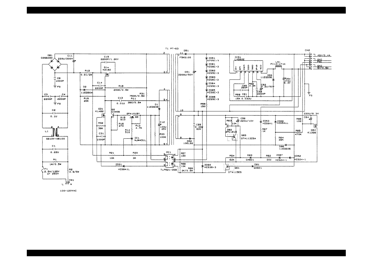
EPSON Stylus Color 440/640/740
Revision B
Chapter 7
Appendix
208
C206PSB 1/1
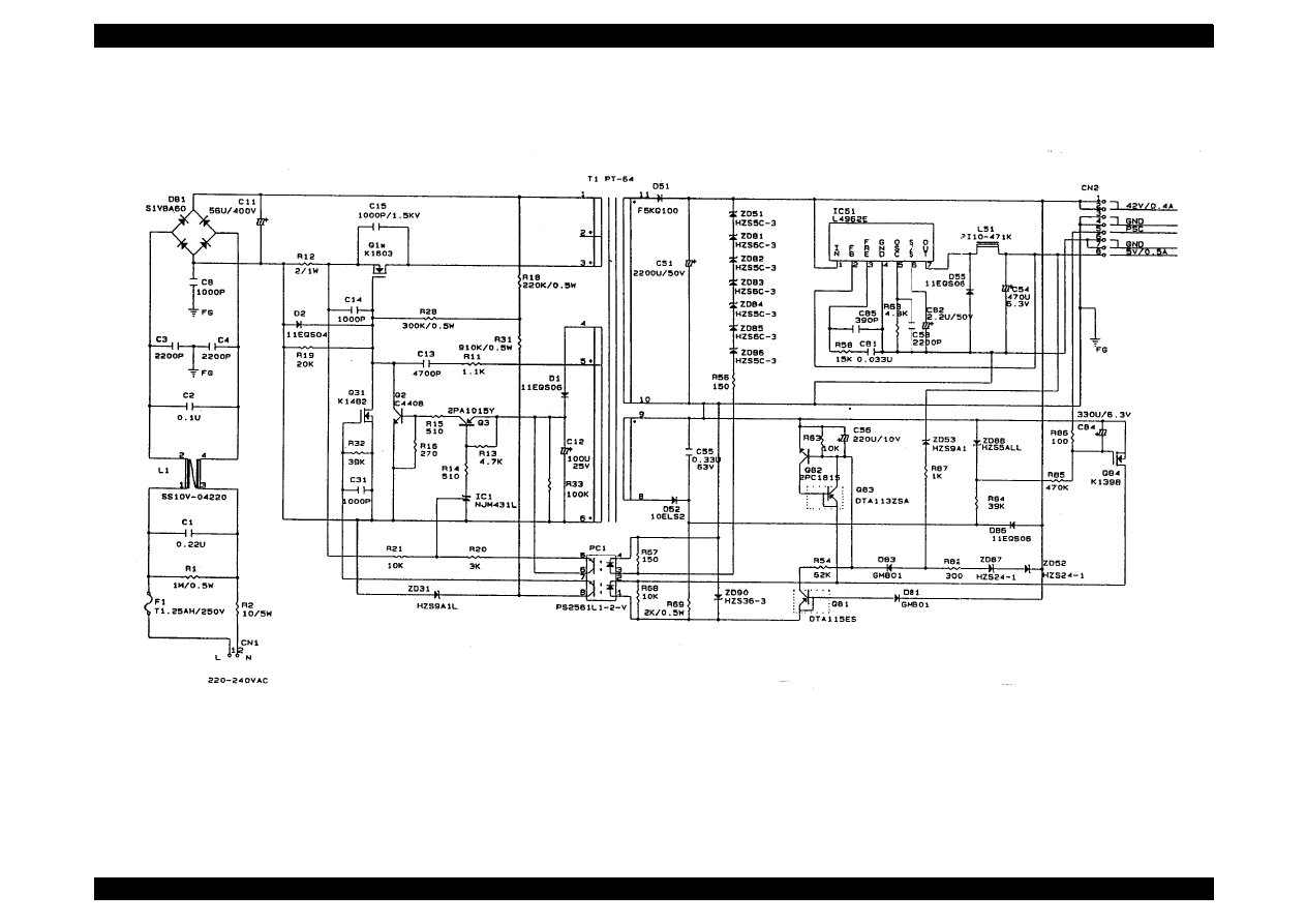
EPSON Stylus Color 440/640/740
Revision B
Chapter 7
Appendix
209
C206PSE 1/1
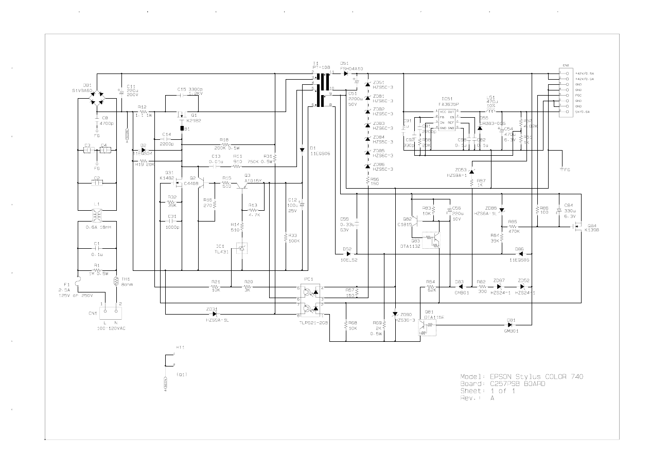
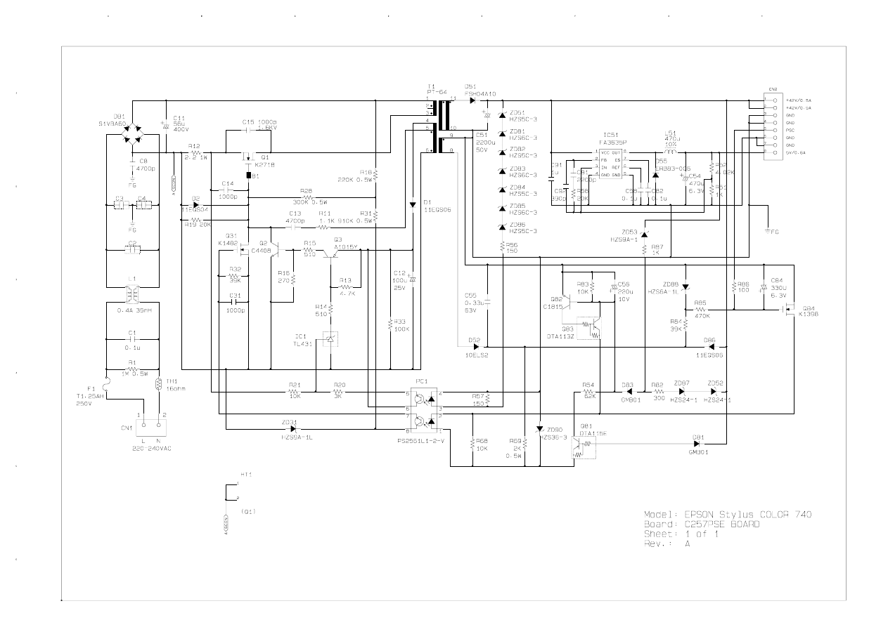
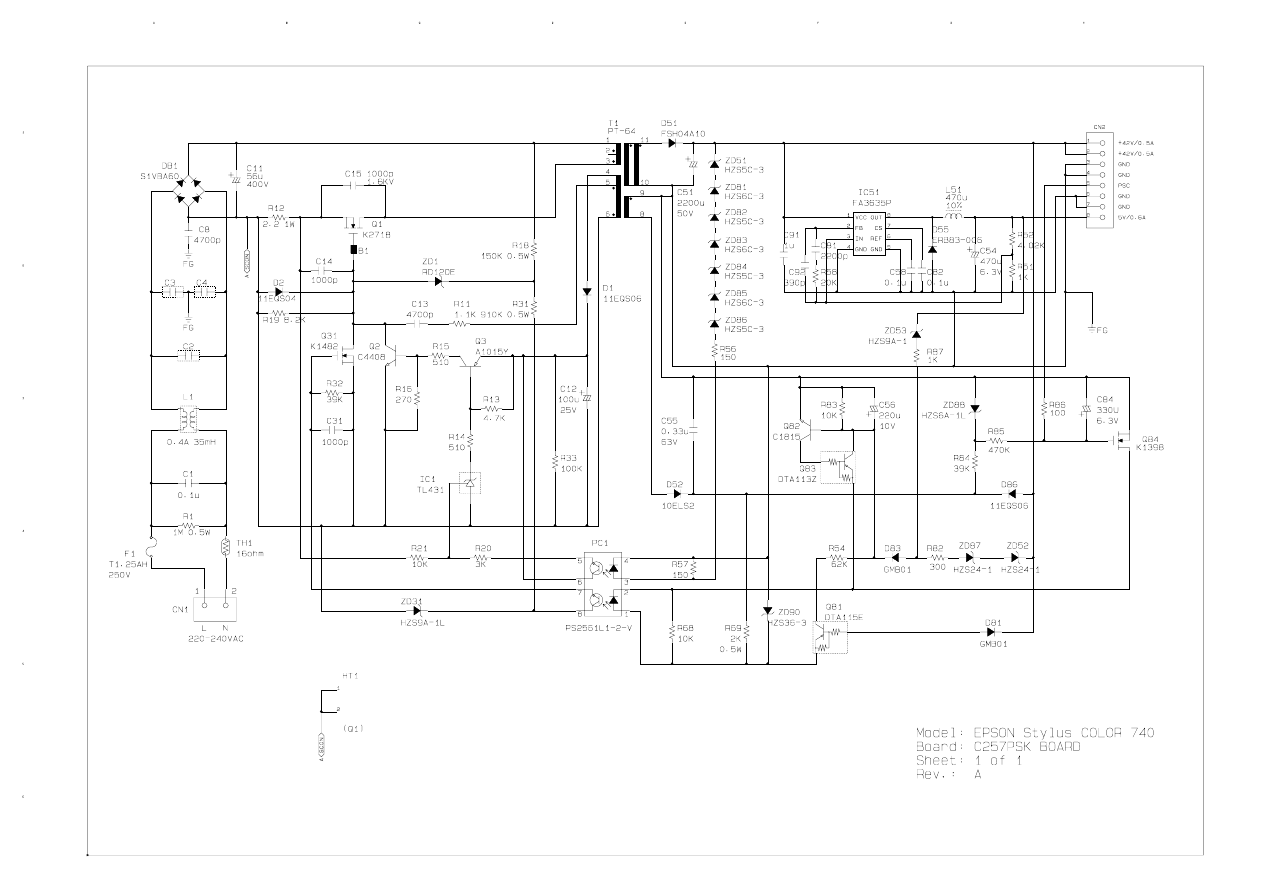
Document Outline
- RETOUR 440
- RETOUR 640
- RETOUR 740
- Stylus Color 440/640/740
- Product description
- 1.1 Features
- 1.2 Specifications
- 1.3 Interface
- 1.4 Control Panel
- 1.5 Error Status
- 1.8 Main Components
- 1.8.1 Printer Mechanism
- 1.8.2 C206 Main-B Board (Stylus Color 440)
- 1.8.3 C256 Main Board (Stylus Color 640)
- 1.8.4 C257 Main Board (Stylus Color 740)
- 1.8.5 Power Supply Board C206 PSB/PSE (Stylus Color 440, 640) C257 PSB/PSE (Stylus Color 740)
- 1.8.6 C206 PNL Board (Stylus Color 440, 640)
- 1.8.7 C209 PNL Board (Stylus Color 740)
- 1.6 Printer Initialization
- 1.7 Initialization Settings
- Operating principles
- Troubleshooting
- Disassembly and assembly
- 4.1 Overview
- 4.2 Disassembly Procedures
- 4.2.1 Removing the Housing
- 4.2.2 Removing the Board Assembly
- 4.2.3 Removing the Operation Panel
- 4.2.4 Disassembling the Printer Mechanism
- 4.2.4.1 Removing the Print Head Unit
- 4.2.4.2 Removing the Absorber Tray Assembly ;A
- 4.2.4.3 Removing the Pump Assembly and Cap Assembly
- 4.2.4.4 Removing the CR Motor Assembly
- 4.2.4.5 Removing the PF Motor Assembly
- 4.2.4.6 Removing the ASF Assembly
- 4.2.4.7 Removing the Carriage Assembly
- 4.2.4.8 Removing the PF Roller Assembly
- 4.2.4.9 Removing the PE Paper Detector Assembly
- 4.2.4.10 Removing the HP Detector
- Adjustment
- 5.1 Overview
- 5.2 Adjustment
- 5.2.1 Parallelism Adjustment
- 5.2.2 Adjustment by Adjustment Program
- 5.2.2.1 About Adjustment Program
- 5.2.2.2 Entering the Main menu
- 5.2.2.3 Initial Ink Charge Operation
- 5.2.2.4 Head Cleaning Operation
- 5.2.2.5 Protection Counter Indicate/Reset
- 5.2.2.6 Market/Destination Check (only for Stylus Color 740)
- 5.2.2.7 Head Voltage ID Input
- 5.2.2.8 Head Angular Adjustment
- 5.2.2.9 Bi-D Adjustment
- Maintenance
- Maintenance
- Appendix
- Product description
Wyszukiwarka
Podobne podstrony:
Epson Stylus Color 440, 640, 740 (2)
Epson Stylus Color 460 Service Manual
Resetter EPSON STYLUS COLOR 460
Epson Stylus Color 300 Service Manual
Epson Stylus Color 700 Stylus Color EX Service Manual
Kartridże atramentowe Epson Stylus C 80
Kartridże atramentowe Epson Stylus C 64
Epson Stylus Pro 9000 Auto Take Up Reel Unit Manual
DRUKARKA EPSON STYLUS MODELE C79 D78
Kartridże atramentowe Epson Stylus C60
Epson Stylus Photo 700 (2)
Epson Stylus Scan 2000 Exploded Diagram
Epson Stylus Pro XL Service Manual
Epson Stylus Scan 2500 Exploded Diagram
więcej podobnych podstron