
EPSON COLOR INKJET PRINTER
Stylus Pro XL+
SERVICE MANUAL
EPSON
4006101

PREFACE
This document provides supplementary information to describe the Stylus Pro XL+, which is a follow-on version
of the Stylus Pro XL. Therefore, you must refer to this information in conjunction with the Stylus Pro XL Service
Manual for details on any subjects common to both printers.
REVISION SHEET
Revision
Issue Date
Revision Page
A
March 15, 1996
-
1st issue
-ii-

1.1 FEATURES
The Stylus Pro XL+ is a high-quality, high-performance color ink jet printer. This printer is provided with a
standard bidirectional parallel interface suitable for the Microsoft
®
Windows™ 95 environment and a serial
interface for the Macintosh. The main components and case of this printer are similar to the Stylus Pro XL.
The main features are:
❒
High-quality color printing
720 dpi printing using EPSON Micro Dot mode
720 dpi printing on:
plain paper
EPSON premium paper
transparencies
❒
High print speed
720 dpi printing of raster graphics at 200 cps
❒
Built-in-3 I/F
Bidirectional parallel interface (IEEE-1284 nibble mode)
Mac serial interface
Type-B interface (optional)
❒
Ink out / low indicators
Black and color ink out / ink low indicator LEDs
Stylus Pro XL+
Product Description
Rev.A
1-1
1.2 SPECIFICATIONS
This section provides statistical facts and other detailed information for the printer.
1.2.1 Printing Specifications
The table below shows print speeds and printable columns.
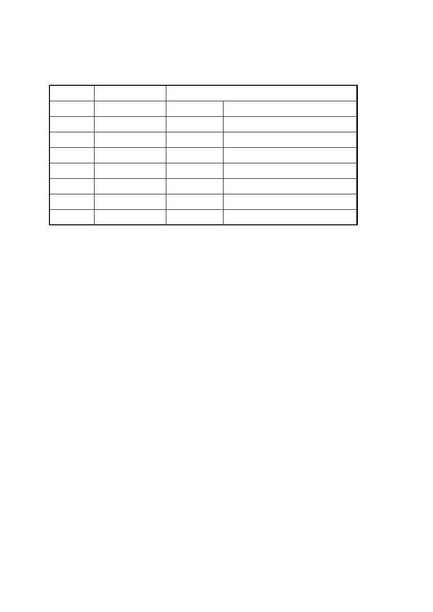
Table 1-1. Print Speed and Printable Columns
Character Pitch
Printable Columns
Print Speeds (LQ)
10 cpi (pica)
127
200 cps
12 cpi (elite)
152
240 cps
15 cpi
190
300 cps
17 cpi (pica condensed)
218
343 cps
20 cpi (elite condensed)
254
400 cps
Graphics Density
Printable Dots
Print Speed (10 cpi)
180 dpi
×
180 dpi
2289
200 cps
360 dpi
×
360 dpi
4578
H — 720 dpi
×
V — 360 dpi
9156
720 dpi
×
720 dpi
9156
Control codes:
ESC/P 2 and expanded raster graphics codes
Input data buffer:
128K bytes
Product Description
Stylus Pro XL+
1-2
Rev.A

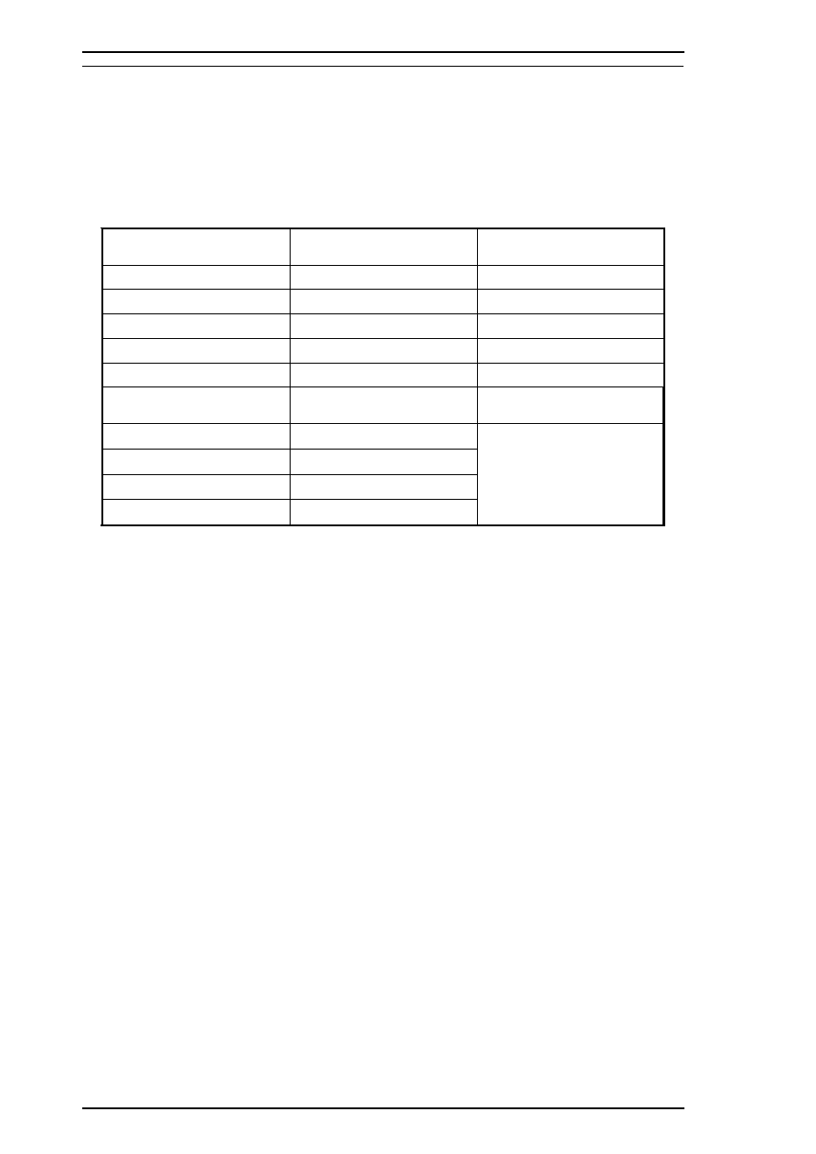
1.2.2 Ink Cartridge Specifications
Black
Type:
Exclusive cartridge
Color:
Black
Print capacity:
1170 pages (ECMA132 letter)
Life:
The effective life from the indicated production date is 2 years.
Storage temperature:
–30
∼
40
°
C (
−
22
∼
104
°
F) Storage under a month at 40
°
C (104
°
F)
−
30
∼
60
°
C (
−
22
∼
140
°
F) Transit under a month at 40
°
C (104
°
F)
−
30
∼
60
°
C (
−
22
∼
140
°
F) Transit under 120 hours at 60
°
C (140
°
F)
Dimensions (W
×
D
×
H):
26.9
×
67.4
×
41.8 mm (1.06
×
2.65
×
1.65 in.)
Color
Type:
Exclusive cartridge
Colors:
Cyan, magenta, yellow
Print capacity:
620 pages (5% duty for each color, A4, 360 dpi)
Life:
The effective life from the indicated production date is 2 years.
Storage Temperature:
–30
∼
40
°
C (
−
22
∼
104
°
F) Storage under a month at 40
°
C (104
°
F)
−
30
∼
60
°
C (
−
22
∼
140
°
F) Transit under a month at 40
°
C (104
°
F)
−
30
∼
60
°
C (
−
22
∼
140
°
F) Transit under 120 hours at 60
°
C (140
°
F)
Dimensions (W
×
D
×
H):
54.0
×
67.4
×
41.8 mm (2.13
×
2.65
×
1.65 in.)
Notes:
❒
The ink cartridge cannot be refilled; it is the only consumable item in the printer.
❒
Do not use an ink cartridge that has exceeded the ink life.
❒
Ink freezes below
−
3
°
C; however, it can be used after it returns to room temperature.
Stylus Pro XL+
Product Description
Rev.A
1-3
1.3 INTERFACE SPECIFICATIONS
The Stylus Pro XL+ comes standard-equipped with two interfaces: an 8-bit bidirectional parallel and an
RS-422 mini-DIN serial interface for the Macintosh. This printer is also equipped with a slot for an optional
Type B interface.
1.3.1 Parallel Interface Specifications
1.3.1.1 Forward Channel
Transmission mode:
8-bit parallel, IEEE-1284 compatibility mode
Synchronization:
By STROBE pulse synchronization
Handshaking:
By BUSY and ACKNLG signals
Signal level:
TTL compatible level
Adaptable connector:
36-pin 57-30360 (Amphenol or equivalent)
Data transmission timing:
See Figure 1-7 of the Stylus Pro XL Service Manual.
Note:
Transition time (rise time and fall time) of every input signal must be less than 0.2
µ
s.
Transition time (rise time and fall time) of every output signal must be less than 0.12
µ
s.
The printer sets the BUSY signal HIGH before setting either the ERROR signal LOW or the PE signal HIGH.
BUSY is held HIGH until all these signals return to their inactive state. The BUSY signal is active (HIGH)
under the following conditions:
❒ During data reception (See Figure 1-7 of the Stylus Pro XL Service Manual..)
❒ When the input buffer is full
❒ When the INIT input signal is active
❒ During initialization
❒ When the ERROR is active
❒ During self-test
❒ During default setting
❒ When the parallel interface is not selected
The ERROR signal is active (LOW) under the following conditions:
❒ When a paper-out error occurs
❒ When a release lever operation error occurs
❒ When a hardware error (a fatal error) occurs
The PE signal is active (HIGH) under the following conditions:
❒ When a paper-out error occurs
Product Description
Stylus Pro XL+
1-4
Rev.A
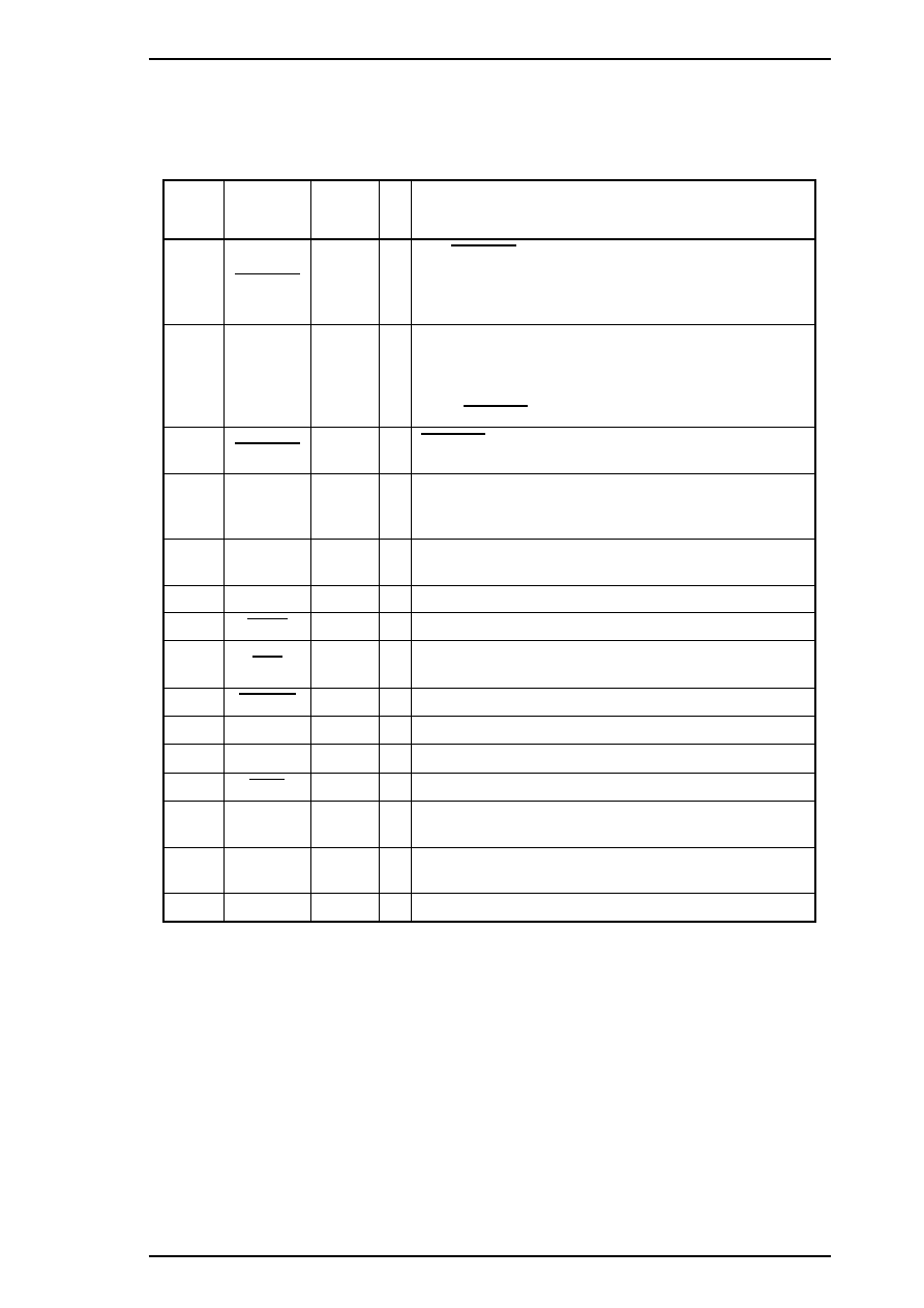
Table 1-2 shows connector pin assignments and signal functions of the 8-bit parallel interface forward
channel.
Table 1-2. Signal and Connector Pin Assignments for the Parallel Interface
(Forward Channel)
Pin No.
Signal
Name
Return
GND Pin
I/O*
Description
1
STROBE
19
I
The STROBE pulse is used to read data from the host
computer. Pulse width must be 0.5
µ
s or more. Normally,
it is HIGH, and data is latched with the rising edge of this
signal.
2-9
DATA 0-7
20 - 27
I
DATA 0-7 are parallel data bits. When one of these
signals is HIGH, the data bit is 1; when LOW, the data bit
is 0. The most significant bit (MSB) is DATA 8. The
signal state must be maintained for 0.5
µ
s on either side
of the STROBE signal’s active edge.
10
ACKNLG
28
O
ACKNLG is a negative pulse indicating that the printer
can accept data again.
11
BUSY
29
O
The BUSY signal informs the host computer of the
printer’s status. When this signal is HIGH, the printer
cannot accept any more data.
12
PE
28
O
This signal indicates whether paper is available in the
printer or not. A HIGH level indicates no paper.
13
SLCT
28
O
This signal is always at HIGH while printer power is on.
14
AFXT
30
I
Not used.
31
INIT
30
I
If this signal goes LOW, the printer is initialized. The
pulse width of this signal must be 50
µ
s or more.
32
ERROR
29
O
This signal goes LOW if the printer has detected an error.
18
Logic H
—
O
Pulled up to +5 V through 3.9K
Ω
resistor in the printer.
35
+5 V
—
—
Pulled up to +5 V through 3.3K
Ω
resistor in the printer.
36
SLIN
30
I
Not used.
17
Chassis
GND
—
—
Chassis ground.
16, 33,
19-30
GND
—
—
Signal ground.
15, 34
NC
—
—
Not connected
*
The I/O column indicates the direction of the signal as viewed from the printer.
Stylus Pro XL+
Product Description
Rev.A
1-5
1.3.1.2 Reverse Channel
Transmission mode:
8-bit parallel, IEEE-1284 nibble mode.
Synchronization:
Refer to the IEEE-1284 specification.
Handshaking:
Refer to the IEEE-1284 specification.
Signal level:
IEEE-1284 level 1 device (See the forward channel.)
Adaptable connector:
The same as for the forward channel.
Data transmission timing:
Refer to the IEEE-1284 specification.
Table 1-3 shows connector pin assignments and signal functions of the 8-bit parallel interface for reverse
channel.
Table 1-3. Signal and Connector Pin Assignments for the Parallel Interface
(Reverse Channel)
Pin No.
Signal Name
Return
GND Pin
I/O*
Description
1
Host Clk
19
I
Host clock signal.
2 - 9
DATA 0 - 7
20 - 27
I
DATA 0-7 signals represent data bits 0 - 7,
respectively. Each signal is at a HIGH level when data
is logical 1 and LOW level when data is logical 0.
These signals are used to transfer the 1284
extensibility request values to the printer.
10
Ptr Clk
28
O
Printer clock signal.
11
Ptr Busy / Data
Bit 3, 7
29
O
Printer busy signal and reverse channel transfer data
bits 3, 7.
12
Ack Data Req /
Data Bit 2, 6
28
O
Acknowledge data request signal and reverse channel
transfer data bits 2, 6.
13
Xflag / Data Bit
1, 5
28
O
X-flag signal and reverse channel transfer data bits
1, 5.
14
Host Busy
30
I
Host busy signal.
31
INIT
30
I
Not used.
32
Data Avail / Data
Bit 0, 4
29
O
Data available signal and reverse channel transfer
data bits 0, 4.
36
1284-Active
30
I
1284 active signal.
18
Logic-H
—
O
A HIGH signal indicates that all other signals sourced
by the peripheral are in valid status.
35
+5V
—
O
Pulled up to +5 V via 3.3K
Ω
resistor.
17
Chassis GND
—
—
Chassis GND.
16, 33,
19 - 30
GND
—
—
Signal GND.
15, 34
NC
—
—
Not connected.
* :
The I/O column indicates the direction of the signal as viewed from the printer.
Product Description
Stylus Pro XL+
1-6
Rev.A

Extensibility Request:
The printer responds affirmatively when the extensibility request values
are 00H or 04H, values that mean —
00H: Request Nibble Mode Reverse Channel Transfer
04H: Request Device ID
Return data using nibble mode reverse channel transfer.
Device ID:
The printer sends following device ID string when it is requested.
[00H][39H]
MFG:EPSON;
CMD:ESCPL2-00;
MDL:Stylus Pro XL+;
CLS : PRINTER;
Note:
[00H] denotes a hexadecimal value of zero.
1.3.2 Optional Interface Specifications
Type-B interface Level-2 (300 mA type) is supported.
Note :
With the simplified serial interface card C82305*, “Disregard a parity bit” setup is not
supported.
Reply message
ESC/P 2 is selected
Main-Type:
MTP48p,PW127cl10cpi,PRG(VCxxxx)rev,AP300ma
Product-Name:
Stylus Pro XL+
Emulation-Type:
ESCP-00
Entity-Type:
EPSONLQ2
Stylus Pro XL+
Product Description
Rev.A
1-7
1.4 OPERATIONS
This section describes the basic operations of the printer.
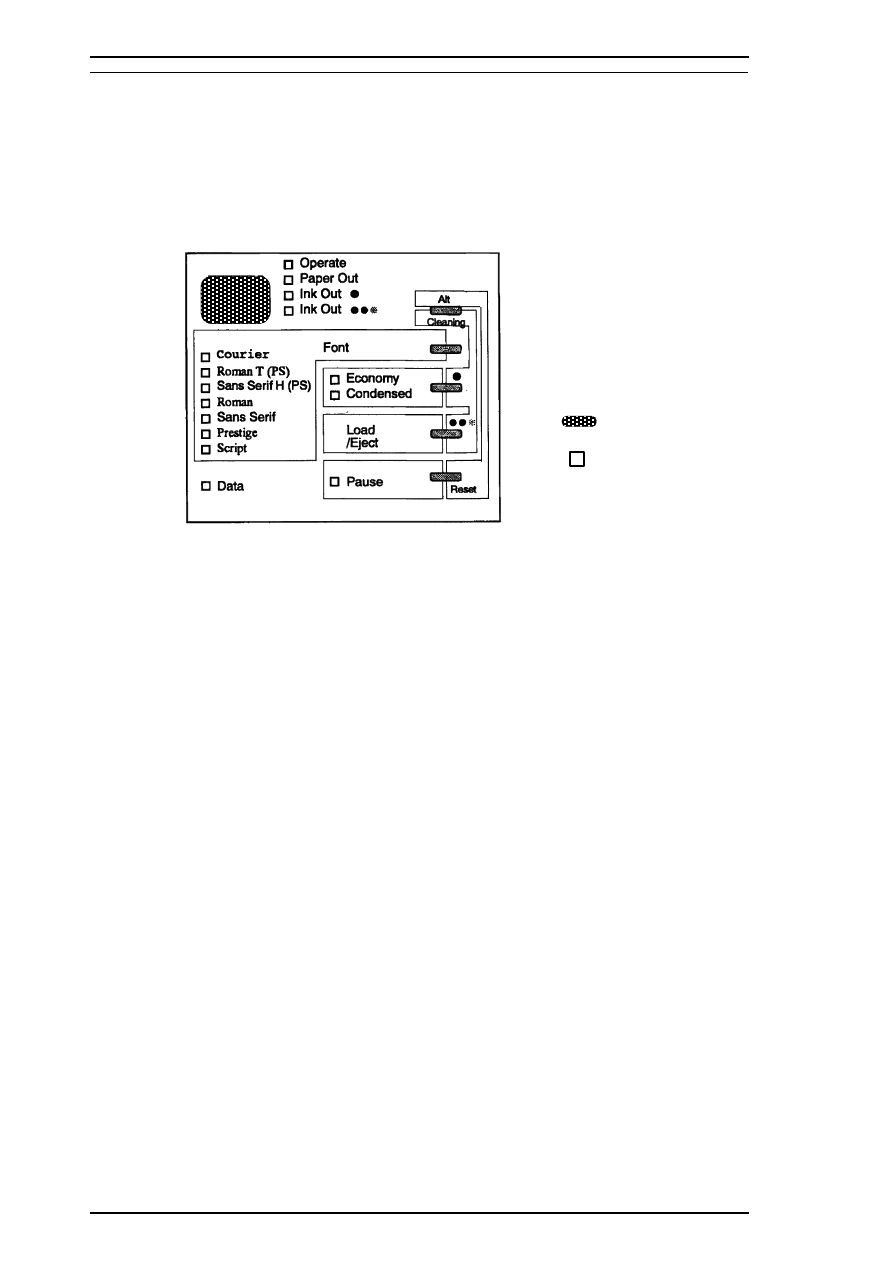
1.4.1 Control Panel
The control panel for this printer has 1 lock-type and 5 non-lock-type pushbuttons, and 15 LED indicators for
easy operation of the various printer functions.
Buttons
Operate
Turns the printer on or off. This button is in the secondary circuit of the
power supply. This lets the printer execute the head-capping function after
it receives the signal to turn off and before actual printer power down.
Alt
Modifies the functions of other buttons. Holding down this button for 3
seconds causes the printer to move the carriage to the ink cartridge
installation position. Pressing Alt again causes the carriage to return to the
home position.
Font
Cycles through the font choices. Pressing the Font button while holding
down the Alt button causes the carriage to move to the gap-adjustment
position. Pressing the Alt button again causes the carriage to return to the
home position.
Economy/Condensed
Selects either economy or condensed printing mode. Pressing the
Economy/Condensed button while holding down the Alt button starts the
black printhead cleaning cycle.
Load/Eject
Either loads a new sheet into the printer or ejects paper currently in the
paper path. Pressing the Load/Eject button while holding down the Alt
button starts the color printhead cleaning cycle.
Pause
Stops printing temporarily or resumes printing if it has been stopped
temporarily. Pressing Pause while holding down the Alt button resets the
printer.
: Button
: LED
Figure 1-1. Control Panel Appearance
Product Description
Stylus Pro XL+
1-8
Rev.A

Indicators
Operate
On when the printer is on. Blinks while the printer is powered on or off.
Paper Out
On when the printer is out of paper. Blinks when a paper jam occurs.
Ink Out (Black)
On when the black ink cartridge is out of ink or not installed. Blinks when
black ink is low.
Ink Out (Color)
On when the color ink cartridge is out of ink or not installed. Blinks when
color ink is low.
Economy
On when economy printing mode is selected.
Condensed
On when condensed printing mode is selected.
Font
These LEDs indicate the selected font.
Pause
On when printing is paused.
Data
On when print data is in the input buffer. Data and Pause lights blink if an
error occurs.
1.4.2 Panel Operation at Power On
The list below contains printer modes and the procedures you can use to activate them:
Self-test mode
Turn on the printer while holding down the Load/Eject button.
Hex dump mode
Turn on the printer while holding down the Font and Load/Eject buttons.
Once this mode is selected, the printer prints all received data in
hexadecimal format.
Default setting mode
Turn on the printer while holding down the Economy/Condensed button.
The printer enters the default setting mode.
Initialize EEPROM
Turn on the printer while holding down the Alt, Font, Load/Eject, and
Pause buttons.
Note:
You can exit self-test, hex dump, or default setting by turning off the printer.
Stylus Pro XL+
Product Description
Rev.A
1-9
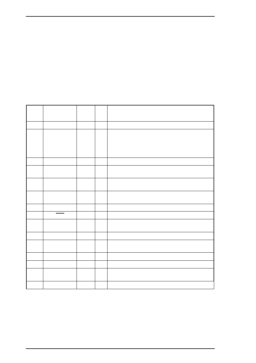
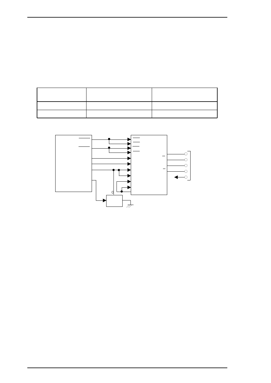
1.4.3 Error Conditions
The printer can detect the various errors and indicate them with LEDs.
Table 1-4. Error Indications
Error
Operate
Paper
Out
Ink
Out
(Black)
Ink
Out
(Color)
Economy Condensed Pause
Data
Paper out
—
On
—
—
—
—
—
—
Black ink end
—
—
On
—
—
—
—
—
Black ink low
—
—
Blink
—
—
—
—
—
Color ink end
—
—
—
On
—
—
—
—
Color ink is low
—
—
—
Blink
—
—
—
—
Paper jam
—
Blinks
—
—
—
—
—
—
Maintenance
request
—
Blinks
Blinks
Blinks
Blinks
Blinks
Blinks Blinks
Carriage error
—
—
—
—
—
—
Blinks Blinks
—
Not used to indicate the specified error.
Product Description
Stylus Pro XL+
1-10
Rev.A
2.1 OPERATING PRINCPLES - OVERVIEW
This section describes the operating principles of the printer mechanism and the electrical circuits of the
Stylus Pro.
2.2 OPERATING PRINCIPLES OF THE PRINTER MECHANISM
2.2.1 Principles of the Printing Operation
The printing mechanism for the Stylus Pro XL+ has a drop-on-demand ink jet system, similar to the system in
all other EPSON ink jet printers. The Stylus Pro XL+ printer uses the Micro Dot printing function both with
black ink and super 720 dpi color printing. The type of Micro Dot printing the Stylus Pro XL+ performs is the
same as is available in the Stylus COLOR II and Stylus COLOR IIs/820. However, with those printers,
Micro Dot printing is available for printing with black ink only. The Micro Dot printing mode can be selected
automatically with 720 dpi printing quality using the printer driver settings described in the following table.
Table 2-1. Special Printing Mode
Paper Type Print Density (DPI) Print Mode
Normal Paper
360 Normal Dot Printing
H — 720
×
V — 360
EPSON Micro Dot Printing
EPSON Premium Paper
for 360 dpi
360 Normal Dot Printing
H— 720
×
V — 360
EPSON Micro Dot Printing
EPSON Premium Paper
for 720 dpi
720 EPSON Micro Dot Printing
Labels for 720 dpi 720 EPSON Micro Dot Printing
High Quality Glossy
Card Stock
720 EPSON Micro Dot Printing
High Quality Glossy Paper 720 EPSON Micro Dot Printing
Transparency film 360 Normal Dot Printing
Micro Dot printing mode can improve output quality, because it eliminates banding that can sometimes occur
in normal mode. The dot size in EPSON Micro Dot Printing mode is smaller than the dot size in normal
printing. Normal print mode is mainly used in resolutions of 360 dpi or less.
Stylus Pro XL+ Service Manual
Operating Principles
Rev.A 2-1
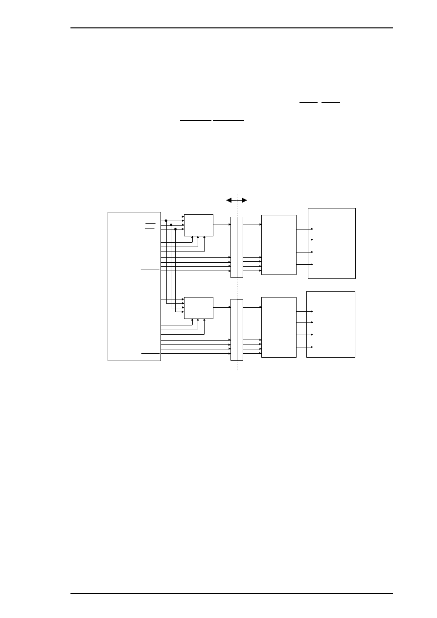
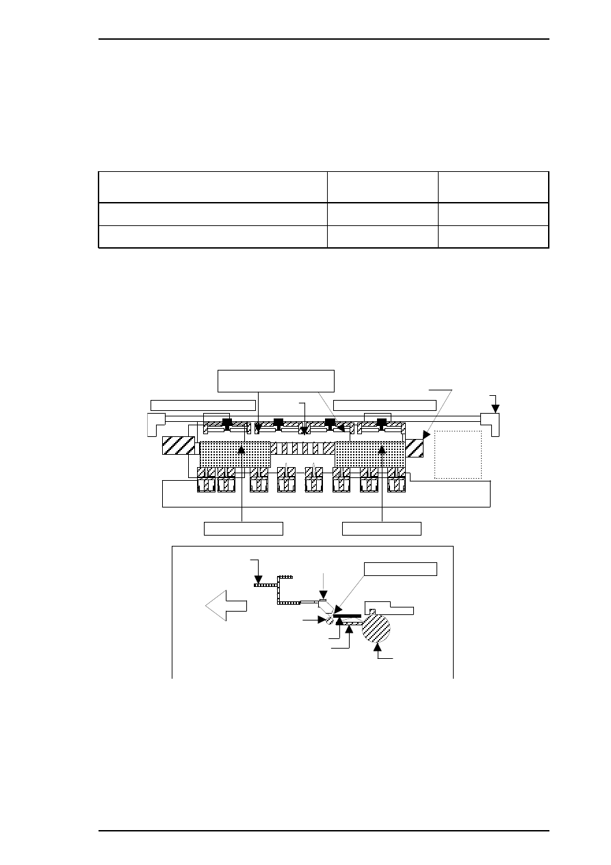
2.3 OPERATING PRINCIPLES OF THE ELECTRICAL CIRCUITS
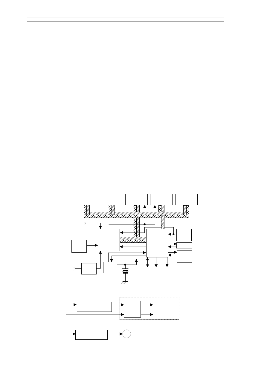
The Stylus Color Pro XL+ contains the following circuit board units:
❒
C184 MAIN board (main control circuit board).
❒
C137 PSB/PSE board (power supply circuit board). This board is the same as Stylus Color’s
❒
C137 PNL (control panel board). This board is similar to Stylus Color’s.
In addition to the circuit boards above, part of the printhead drive circuit is built on a separate circuit board
installed in the carriage unit; the printhead is attached directly to this board. The figure below shows a block
diagram of the electrical circuits.
2.3.1 Operating Principles of the Main Control Circuit
The main control circuit for this printer is the C184 MAIN board. This circuit is controlled by a 16-bit
H8/3003 CPU (IC1), running at 14.7456 MHz. The CPU has a unique architecture, capable of handling data
on the data bus at either an 8-bit or 16-bit bus width. Because of this, both a 16-bit and an 8-bit data bus
width-type ROM can be used on the board, increasing the internal processing speed. Also, the CPU’s unique
architecture is capable of refresh control. In addition, the CPU controls the serial interface (RS-422 for Mac)
and optional interface (Type B interface).
Gate array E05B21 (IC2) manages the printhead driver, the external Centronics
®
parallel interface, the
extension CG board, and the control panel. The gate array also oversees the controls that create the 4-bit
signals for the carriage or the paper feed motor. (The carriage and paper feed motor are controlled by current
duty data.) This board also is equipped with a 93C46 EEPROM (IC11) to store certain parameters, such as the
black/color head data, printer mechanism control parameters, default setting parameters, as well as a special
counter value used for printhead (ink management) protection.
Timer IC NJU6355E (IC10) counts each time the printer goes through its cleaning cycle and keeps track of
how much time has elapsed since the printer has been used, thereby allowing the printer to be cleaned only
when necessary. The timer value is backed up by the lithium battery.
M
C L K
S D I / O
D M A R E Q
D - R A M ( 4 M )
(IC5)
D - R A M ( 4 M )
(IC6)
E E P R O M
(IC11)
93 C 4 6
(IC8)
M 51955B
V x
N J U 6 3 5 5 E
( T ime r C ou nte r )
(IC10 )
(IC9)
P ST 5 92D
R S- 4 22
Seri al I/F
T
o
A
T
o
B
From A
From B
C 184 M AIN B oa r d
S E D 6 1 1 0 D O A
(U 1, U2)
SL A7 04 3 M ( I C 1 4 , 1 5 )
H8/3003
(IC1)
C P U
E 05 B2 1
(IC2)
B l a c k 6 4 No z zl e s
C ol or 48 Nozzl es
C ar ria ge / Pa pe r Fe ed
Mot or D ri ver
M R O M ( 4 - 3 2 M )
(IC7)
P- R OM ( 4M )
(IC3)
P- R O M ( 1 - 4M )
(IC4)
T y p e - B I / F
H 8 D 2 7 7 8 A ( I C 1 6, 1 7)
S N 7 5 L B C 7 7 5
(IC13 )
D a ta Bus
Ad dr es s Bu s
R ef r es h
R e se t (P ow e r)
R e se t ( Log i c )
P a n e l
Black/C ol or H ead
C om m on D ri ver Ci r cui t
P
a
ra
lle
l I/
F
Ca
rr
iage /
Paper
Feed
M
o
to
r D
ri
v
e
r
S
ignal
B
lack /
C
o
lo
r
H
e
a
d
C
o
m
m
on and N
o
z
z
le
S
e
le
c
to
r Dr
iv
e
Si
gnal
Figure 2-1. Main Control Circuit Block Diagram
Operating Principles
Stylus Pro XL+ Service Manual
2-2
Rev.A
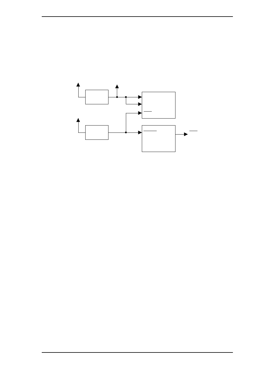
2.3.2.1 Reset Circuits
The C184 MAIN board contains 2 reset circuits: the +5 V monitor reset circuit and the +35 V monitor reset
circuit. The +5 V monitor reset circuit monitors the voltage level of the +5 V line (logic line), using reset IC
PST592D (IC9), and outputs a reset signal to the CPU (IC1) and the E05E21 gate array (IC2) when the
voltage level drops below +4.2 V. The +35 V monitor reset circuit monitors the voltage level of the +35 V
line, using reset IC M51955B (IC8), and outputs a reset signal to the CPU. The reset signal is generated when
the voltage level drops below +28 V, and this causes a non-maskable interrupt (NMI).
+35 V
+5 V
NMI
P 6 2
CPU (IC1)
+5 V
PST592D
(IC X)
E05B21 ( IC2)
R E S
RESET
80
71
1
6
72
68
M 5 19 55 B
(IC8)
TBRST
RST
Type B
55
Figure 2-2. Reset Circuit Block Diagram
Stylus Pro XL+ Service Manual
Operating Principles
Rev.A
2-3
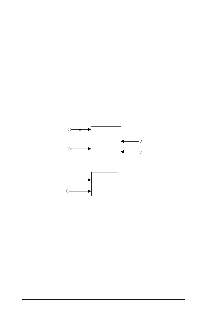
2.3.2.2 Sensor Circuits
The following sensor circuits enable the C184 MAIN board to monitor printer mechanism status:
HP sensor
A photocoupler-type HP (home position) sensor is attached to the surface of the printer
mechanism to detect the carriage home position. A HIGH level from the signal indicates
that the carriage is in home position.
PE sensor
A mechanical switch PE (paper end) sensor is built into the printer mechanism to determine
whether there is paper in the printer or not. A LOW level from the signal indicates that no
paper is loaded.
BCO sensor,
CCO sensor
Micro switches (BCO sensor for the black ink cartridge, CCO sensor for the color ink
cartridge) are attached to the bottom of ink cartridge holder in the carriage unit. When the
ink cartridge is installed, these switches are pressed and a LOW level from the signal
indicates that the ink cartridge is installed into the ink cartridge holder. These sensing
timing is only in the cartridge installation mode and one minute after the carriage holed to
prevent from miss censoring owing from switch actuators shock in printing condition.
Thermistor
A thermistor is attached to the color printhead driver board to monitor its temperature using
the thermistor’s resistance value (at 25
°
C (77
°
F), the normal value is approximately
10K
Ω
). The CPU changes the printhead drive signal’s pulse width (charge pulse width)
based on the temperature level.
TH
(CN12)
CCO
181
CPU (IC1)
SWA0
HP
PE
(CN8)
(CN9)
180
BCO (CN11)
GA (IC2)
AN0
86
SWC1
SWC2
(CN12)
4
3
SWC0
5
PB3
Figure 2-3. Sensor Circuit Block Diagram
Operating Principles
Stylus Pro XL+ Service Manual
2-4
Rev.A
2.3.2.3 Carriage Motor Driver Circuit
Carriage motor driver IC SLA7043 (IC15) outputs a constant current to drive the carriage motor in the printer
mechanism. Gate array E05B21 (IC2) decides the motor phase and speed, and then it sends a signal to the
carriage motor driver IC (SLA7043), using the 4-bit serial transmission line. The first bit indicates the
direction of motor rotation. The other three bits (a, b, c) are current duty data for the motor speed for each
printing sequence. (Refer to Table 2-2, below.)
SLA7043 can select the reference voltage itself based on these three bits of current duty data. Also, the driver
IC receives these signals via two serial transmission lines for the two motor phases (phase A and phase B). As
a result, the carriage motor can be driven in micro step sequence (
1
⁄
720
inches, minimum). The SLA7043
motor driver reads four-bit serial data using four clock counts from the E05B21 (IC2) clock.
Each bit is read at the falling edge of the clock pulses. Then, received serial data is written into the shift
register and then shifted the latch register. When the strobe pulse becomes active from the E05B21 (IC2),
serial data is moved into the reference voltage selection circuit and the voltage is changed. Therefore, when
the printer is in the constant speed mode, this strobe pulse becomes inactive. The following table indicates the
current duty of each carriage motor speed mode.
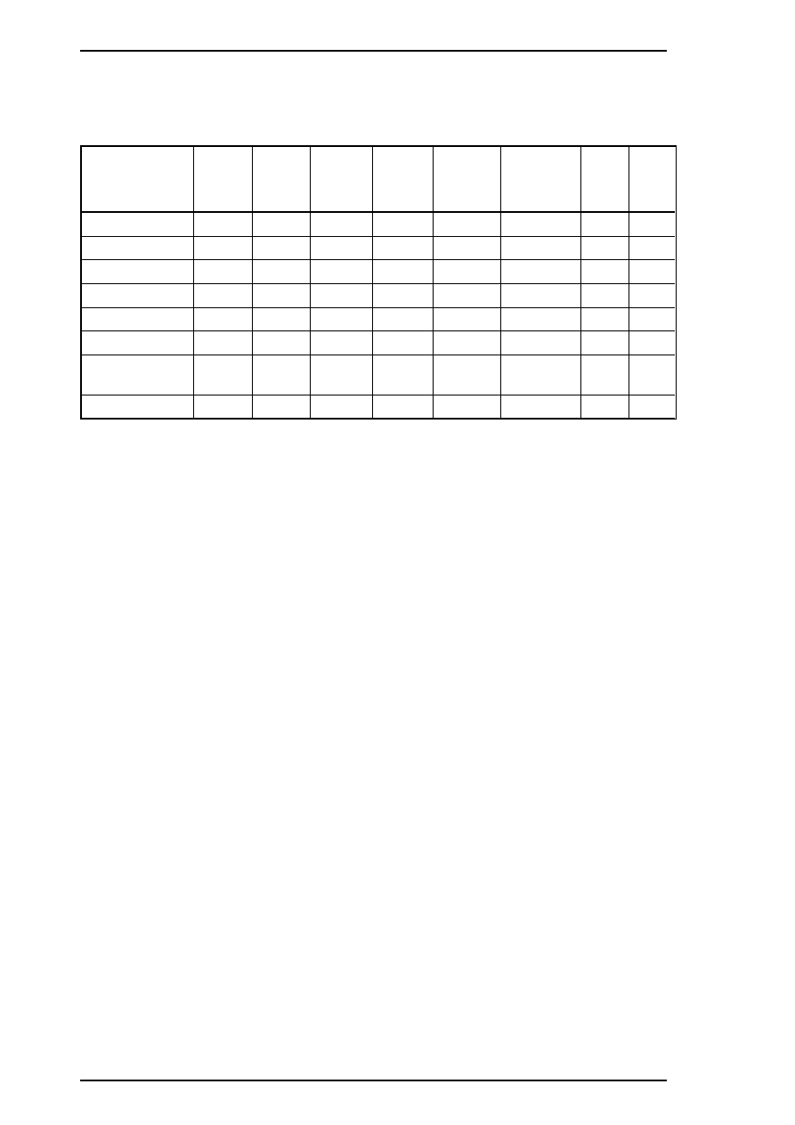
Table 2-2. Serial Data Contents
Mode
c b a*
Vref (Typical)
0
0 0 0
Vref
×
1/3
(Vref = +5 V)
×
0%
1
0 0 1
×
20%
2
0 1 0
×
40 %
3
0 1 1
×
55.5%
4
1 0 0
×
71.4%
5
1 0 1
×
83%
6
1 1 0
×
91%
7
1 1 1
×
100%
*
“a” indicates the 2nd bit, “b” indicates the 3rd bit, and “c” indicates the 4th bit.
The following figure shows 4-bit serial data and how this data is transferred by the SLA7043 driver. The step
time for the reference voltage is determined by the interval time of the strobe pulse.
E05B21
(IC2)
199
196
198
197
CRBSO
CRSTB
CLKA
5
16
2
13
CRASO
SLA7043
(IC15)
CLKB
STBA
STBB
DATA A
DATA B
6
17
CRV0-5
REF A
REF B
CRHOLD
RSA
RSB
3
14
9
10
CRCLK
B
E
C
A
A
B
B
1
8
11
18
1
2
3
4
+
3
5
V
5
(CN6)
5-10
205
GND
Q5
Figure 2-4. Carriage Motor Circuit Block Diagram
Stylus Pro XL+ Service Manual
Operating Principles
Rev.A
2-5
2.3.2.4 Paper Feed Motor Driver Circuit
The paper feed motor for this printer drives the following mechanisms:
❒
Paper feed mechanism
❒
Paper pickup mechanism
❒
Pump mechanism
Driver IC SLA7043 (IC14) drives the paper feed motor by a constant current. The principle of operation is
same as for the carriage motor driver circuit. However, the paper feed motor drives not only the paper feed
mechanism but also the pump unit. (Refer to Section 2.3.2.4.)
Table 2-3. Paper Feed Motor Drive Modes
Mode
Phase Excitation
Drive Frequency
Paper feed
2-2 phase or 2W1-2 phase
391 or 1600 pps
Pump drive
2-2 phase
300 or 1800 pps
E05B21
(IC2)
204
201
198
202
PFBSO
PFSTB
CLKA
5
16
2
13
PFASO
SLA7043
(IC14)
CLKB
STBA
STBB
DATA A
DATA B
6
17
PFV0-2
REF A
REF B
PFHOLD
RSA
RSB
3
14
9
10
PFCLK
B
E
A
A
B
B
1
8
11
18
1
2
3
4
+
3
5
V
5
(CN7)
205
GND
Q4
11-13
Figure 2-5. Paper Feed Motor Driver Circuit Block Diagram
Operating Principles
Stylus Pro XL+ Service Manual
2-6
Rev.A
2.3.2.5 Printhead Driver Circuit
The printhead driver circuit for this printer is composed of the following two parts:
❒
Common driver circuit (common drive pulse generation)
❒
Head driver circuit (nozzle control built on the printhead)
The common driver circuit is hybrid IC H8D2778A on the C184 MAIN board. The head driver circuit is IC
SED61110D0A on the printhead unit itself. The printhead drive signals are output from gate array E05B21.
They consist of the common driver control signals (SBDT/SCDAT, SCLK, SSTB, SCLR, BH1C0/CH1C0,
BH1C1/CH1C1, BH1D/CH1D, BHDIS/CHDIS) and the nozzle select signals (BHDAT/CHDAT,
BHCLK/CHCLK, BHLAT/CHLAT, BHNCHG/CHNCHG).
The common driver control signals from gate array E05B21 are translated to common drive voltage pulses by
IC H8D2778A and input to each printhead nozzle PZT. The nozzle select signals are also output from gate
array E05B21 to SED6110D0A on the head unit to select the print nozzles. Then the ink dots are ejected from
the selected nozzles.
E05B21 (IC2)
COM
SED6110DOA
(U1)
CN1
1
C
N
1
LAT
CLK
SI
C184 MAIN
On Carriage (Head Driver Board)
SBDAT
SCLK
SSTB
SCLR
H8D2778A
BH1C0/1
BH1D
BHDIS
BHCLK
BHLAT
BHDAT
BHNCHG
SED6110DOA
(U2)
LAT
CLK
SI
H8D2778A
SCDAT
CH1C0/1
CH1D
CHDIS
CHCLK
CHLAT
CHDAT
CHNCHG
CN
1
2
C
N
1
COM
Common Driver
Common Driver
Black Head Nozzles
Color Head Nozzles
Figure 2-6. Printhead Driver Circuit Block Diagram
Stylus Pro XL+ Service Manual
Operating Principles
Rev.A
2-7
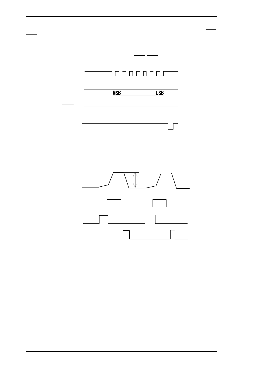
Common Driver Signals
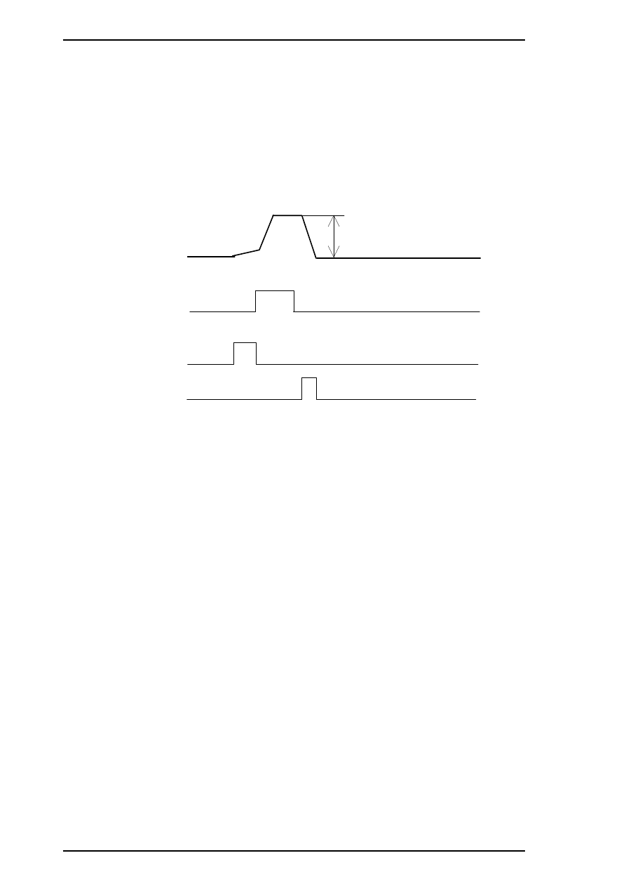
The common driver control signals consist of the common voltage control signals (SBDAT/SCDAT, SSTB,
SCLR, SCLK) and the common drive pulse generation signals (BH1C0/CH1C0, BH1C1/CH1C1,
BH1D/CH1D, BHDIS/CHDIS). The common voltages (VH), ranging between the maximum voltage and 0
(V), are split into 256 levels, which are then translated into 8-bit serial data for the common voltage control
signal (BHDAT/CHDAT), which is output from gate array E05B21 to the common driver H8D2778A to fit
with each printhead specifically. The signals are received by SSTB, SCLR and SCLK to the common driver.
After the common voltage (VH) is stabilized, common drive pulse generation signals are translated to
generate the common drive pulses from gate array E05B21 to the H8D2778A common driver.
SCLT
SDAT
SCLR
SSTB
H
L
H
L
H
L
H
L
Figure 2-7. Common Driver Signal Timing Chart
VH
C O M
BH 1C 0/C H 1C 0
BH 1C 1/C H 1C 1
B H 1 D / C H 1 D
Figure 2-8. Common Drive Pulses
Operating Principles
Stylus Pro XL+ Service Manual
2-8
Rev.A
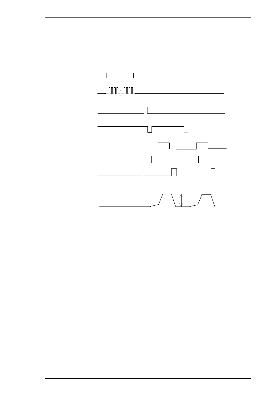
Nozzle Select Signals
The nozzle select signals are output from gate array E05B21 to SED6110D0A on the head unit to select the
printhead nozzles. Nozzle select data (BHDAT/CHDAT) is HIGH for selected nozzles and LOW for
unselected nozzles. Nozzle select data translation timing is controlled by 64 clock signals (BHCLK/CHCLK),
one for each nozzle. After the print nozzles are selected, the common drive pulses are input to each PZT on
the selected nozzles via SED6110D0A. Then the ink dots are ejected from each selected nozzle’s PZT.
VH
COM
BH1C0/CH1C0
BH1C1/CH1C1
BH1D/CH1D
BHNCHG/CHNCHG
BHLAT/CHLAT
BHCLK/CHCLK
BHDAT/CHDAT
# 1
# 64
Figure 2-9. Common Drive / Nozzle Select Signal Timing
(Normal Dot Printing)
Stylus Pro XL+ Service Manual
Operating Principles
Rev.A
2-9
Normal Dot Versus EPSON Micro Dot Printing Mode
The Stylus Color Pro XL+ can eject ink in two different modes (normal print mode and EPSON Micro Dot
Mode). These modes are the same as the modes used in the Stylus Color II/Stylus Color IIs. (Refer to Section
2.2.1.) However, EPSON Micro Dot Printing in the Stylus Color II and Stylus Color IIs can be used only for
printing with black ink. EPSON Micro Dot Printing in the Stylus Pro XL+ can be used with both black and
color printing.
In normal dot printing, a pair of common drive pulses are translated to the printhead to produce one dot. On
the other hand, one print dot consists of single dot in the EPSON Micro Dot Printing. A single common drive
pulse is translated to the printhead, as shown in the following figure.
VH
COM
BH1C0/CH1C0
BH1C1/CH1C1
BH1D/CH1D
Figure 2-10. Common Drive Pulse for EPSON Micro Dot
Operating Principles
Stylus Pro XL+ Service Manual
2-10
Rev.A
2.4 INK SYSTEM MANAGEMENT
This section explains how the ink system is managed to protect the printhead and the ink supply system and to
ensure high-quality output. Ink system operations are controlled by the following counters:
❒
Protect counter
❒
Ink consumption counter
2.4.1 Counters
EEPROM 93C46 (IC11) on the main board stores the counter values used for controlling ink system
operation.
2.4.2.1 Protect Counters
The values of protect counters A and B, C are stored in the EEPROM on the main board, and while the printer
is on, this data is also stored in the RAM on the main board.
❒ Protect counter A
This counter manages the total amount of drained ink. If the counter value
is equal to or exceeds 51,000, the printer indicates an error on the control
panel indicating that maintenance is required.
Notes for Service
Protect counter A is reset:
1. Upon shipment from the factory.
2. After maintenance is performed (whenever you replace the ink drain tank).
❒ Protect counter B, C
These counters set limits to prevent the user from frequent initial ink
charging. The counters values are stored in the EEPROM as flags and are
reset by the EEPROM reset function.
2.4.2.2 Ink Consumption Counter
This counter manages black and color ink consumption. The counter is counted up during printing,
automatically. It also counts compulsory head cleaning and the interval times between usage of the ink
cartridge. This counter is only reset by the installation of a new ink cartridge.
Stylus Pro XL+ Service Manual
Operating Principles
Rev.A
2-11
3.1 DISASSEMBLY AND ASSEMBLEY - OVERVIEW
This section describes procedures for disassembling the main components of the printer. Unless otherwise
specified, disassembled units or components can be reassembled by reversing the disassembly procedure.
Therefore no assembly procedures are included. Precautions for any disassembly or assembly procedure are
described under the heading “Disassembly/Assembly Points.” Adjustments required after assembling the unit
are described under the heading “Required Adjustments.”
3.1.1 Precautions for Disassembling the Printer
See the precautions below when disassembling the printer.
WARNING
❒ Disconnect the power cable before disassembling or assembling the printer.
❒ Wear protective goggles to protect your eyes from ink. If ink gets in your eye, flush it with
fresh water and see a doctor immediately. If ink comes into contact with your skin, wash it
off with soap and water. If irritation occurs, contact a physician.
❒ A lithium battery is installed on the C184 MAIN Board of this printer. Be sure to observe
the following instructions when servicing the battery:
1. Keep the battery away from any metal or other batteries so that electrodes of opposite
polarity do not come in contact with each other.
2. Do not heat the battery or put it near fire.
3. Do not solder on any part of the battery. (Doing so may result in leakage of electrolyte
from the battery, burning, or explosion. The leakage may affect other devices close to the
battery.)
4. Do not charge the battery. (An explosive gas may be generated inside the battery, and
cause burning or explosion.)
5. Do not dismantle the battery. (The gas inside the battery may hurt your throat. Leakage,
burning, or explosion may also result.)
6. Do not install the battery in the wrong direction. (This may cause burning or explosion.)
CAUTI
O
N
There is danger of explosion if the battery is incorrectly replaced. Replace only with the same or
equivalent type recommended by the manufacturer. Dispose of used batteries according to
government’s laws and regulations.
ATTENTION
Risque d’explosion si la pile est remplacée incorrectement. Ne remplacer que par une pile du
même type ou d’un type équivalent recommandé par le fabricant. Elminer les piles déchargées
selon les lois et les règles de sécurité en vigueur.
CAUTI
O
N
❒ Never remove the ink cartridge from the carriage unless specified to do so.
❒ When transporting the printer after the ink cartridge has been installed, be sure not to remove
the ink cartridge when you pack the printer for shipping.
❒ Use only recommended tools for disassembling, assembling, or adjusting the printer.
❒ Apply lubricants and adhesives as specified. (See Stylus Pro XL Service Manual Chapter 6.)
❒ Make specified adjustments when you disassemble the printer. (See Chapter 4.)
Stylus Pro XL+ Service Manual
Disassembly and Assembly
Rev.A 3-1
3.2 DISASSEMBLY AND ASSEMBLY
CAUTION
❒ When you remove the ink cartridge, always install a new cartridge immediately after taking
out the old one.
❒ When you replace the ink cartridge, the printer performs the ink cartridge replacement
operation automatically.
The exclusive service cartridges have the following part numbers:
Monochrome:
1020626
YMC:
1027990
❒ Never keep ink cartridges longer than 6 months.
3.2.1 Printer Mechanism Disassembly
The procedures described in this section explain how to remove components in the printer mechanism.
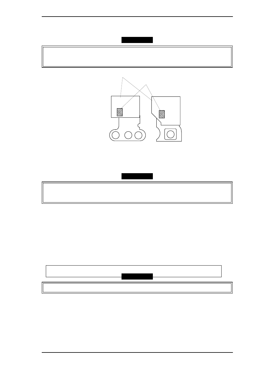
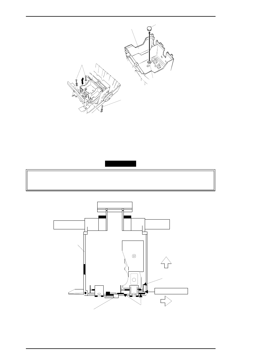
3.2.1.1 Carriage Unit Removal
1.
Remove the printer mechanism. (See Stylus Pro XL Service Manual, Section 3.2.4.)
2.
Move the carriage to the left side of the printer while pressing the hook that fixes the carriage to the
home position.
3.
Remove the 2 CBS (O) (M3
×
6) screws securing the front frame to both side frames.
4.
Remove the cartridge holder with from the carriage unit. (See the Stylus Pro XL Service Manual,
Section 3.2.5.1.)
5.
Release the carriage timing belt from the belt pulley while pressing the pulley lever.
6.
Remove the both sides flange nuts and plain washers.
7.
Remove 2 parallelism adjustment bushings and carriage shaft spacers from both side frames.
8.
Take off carriage shaft spacer L and carriage shaft spacers B, C, or D (if they have been installed).
Carriage Guide Shaft
Carriage Shaft Spacer R
Carriage Guide Shaft
Left Side Frame
Right Side Frame
Parllelism Adjust Bushing
Parllelism Adjust Bushing
Plain Washer
Plain Washer
Carriage Shaft Spacer
Carriage Shaft Spacer
Carriage Shaft Spacer L
Carriage Shaft Spacer L;B
Carriage Shaft Spacer L;C
Carriage Shaft Spacer L;D
Flange Nut (M4)
Flange Nut (M4)
Figure 3-1. Fixing the Carriage Guide Shaft
Stylus Pro XL+ Service Manual
Disassembly and Assembly
3-2
Rev.A
9.
Lift the carriage unit with the carriage guide shaft out of the printer mechanism.
CAUTION
❒ Take appropriate measures to protect the printhead unit from static electricity, because the
driver IC is directly attached to the printhead unit.
❒ Never touch the metallic nozzle surface of the printhead cover. Handle it only by holding the
edges of the printhead.
❒ After you have replaced the printhead or the printer mechanism, you must perform the
head data writing operation before any other adjustments. (See Section 4.1.1.)
❒ Put the carriage shaft spacers L, B, C and D between the left frame and the carriage guide
shaft to minimize the gap between them. The adjustable range is from 0.8 mm to 1.8 mm.
The thickness of carriage shaft spacers are as follows:
Carriage Shaft Spacer L
0.6 mm
Carriage Shaft Spacer L and B
0.8 mm
Carriage Shaft Spacer L and C
1.0 mm
Carriage Shaft Spacer L and D
1.2 mm
ADJUSTMENT REQUIRED
❒ Platen gap adjustment (See Chapter 4.)
Stylus Pro XL+ Service Manual
Disassembly and Assembly
Rev.A
3-3
4.1 ADJUSTMENT - OVERVIEW
This section describes adjustments required when the printer is disassembled and assembled after repair.
Since this printer has both a black and color head, it needs new adjustments not required for previous printers.
Refer to the following table to perform the appropriate adjustments.
CAUTI
O
N
❏ Always perform adjustments in the order indicated.
❏ After performing steps 1-5, do the cleaning operation for the black and color printheads.
The cleaning operation is necessary, because printing sample patterns for the head angle,
Bi-D alignment, and the head gap increases the viscosity of the ink, and the printer will
not print the correct value. For instance if you replace the black head, you must do the
following adjustments in the order shown:
(1) Black head angle, (2) black-color head vertical, (3) head gap, (4) Bi-D alignment.
❏ After removing an ink cartridge, always install a new cartridge immediately. During
adjustments and testing, use cartridges designed exclusively for service
(Monochrome: 1020626, CMY: 1027990 )
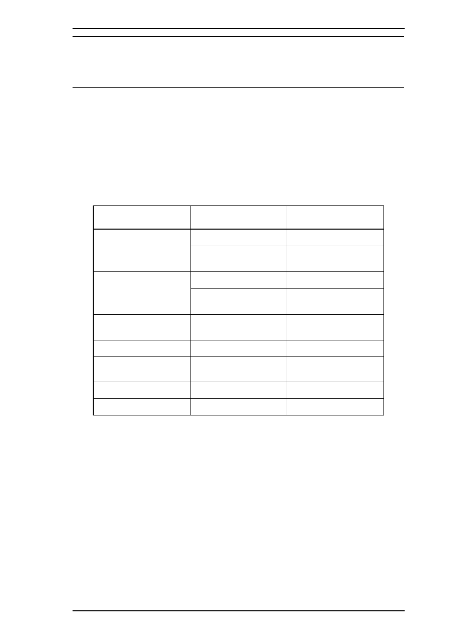
Table 4-1. Required Adjustments
Service Performed Adjustment Needed
When replacing the
printer mechanism
1. Writing head data (see Section 4.1.1)
2. Bi-D alignment adjustment (see Section 4.1.2).
3. Head gap adjustment (see Section 4.1.3).
When replacing or
disassembling the main
board or printer mechanism
1. Writing head data (see Section 4.1.1)
2. Bi-D alignment adjustment (see Section 4.1.2).
3. Head gap adjustment (see Section 4.1.3).
When replacing or
disassembling the
black head (board)
1. Writing head data (see Section 4.1.1)
2. Black head angle adjustment (see Section 4.1.4).
3. Black - color head vertical adjustment (see Section 4.1.5).
4. Head gap adjustment (see Section 4.1.3).
5. Bi-D alignment adjustment (see Section 4.1.2).
When replacing or
disassembling
the color head (board)
1. Writing head data (see Section 4.1.1)
2. Color head angle adjustment (see Section 4.1.6).
3. Black - color head vertical adjustment (see Section 4.1.5).
4. Head gap adjustment (see Section 4.1.3).
5. Bi-D alignment adjustment (see Section 4.1.2).
When replacing or
disassembling both the
color and black head
1. Writing head data (see Section 4.1.1)
2. Color head angle adjustment (see Section 4.1.6).
3. Black head angle adjustment (see Section 4.1.4).
4. Black - color head vertical adjustment (see Section 4.1.5).
5. Head gap adjustment (see Section 4.1.3).
6. Bi-D alignment adjustment (see Section 4.1.2).
When replacing or
disassembling
the carriage unit
1. Platen gap adjustment (see Section 4.1.7).
2. Writing head data (see Section 4.1.1)
3. Bi-D alignment adjustment (see Section 4.1.2).
4. Head gap adjustment (see Section 4.1.3).
NOTE:
The destination data writing operation (see Section 4.1.2) is performed automatically
when you quit the program from the adjustment main menu and turn off the printer.
When you need to replace the printer mechanism, you will find the head data information
written on the outside of carton containing the printer mechanism.
Stylus Pro XL+ Service Manual
Adjustment
Rev.A 4-1
4.1.1 Head Data Writing Operation
Data unique to the specific black and color printhead used in the printer is stored in the EEPROM on the
C184 MAIN board. These values must be written to the EEPROM first when the printhead unit, the printer
mechanism, main board, or EEPROM chip is replaced. However, it is not necessary to write them to
EEPROM again, even if the EEPROM is reset from the control panel.
CAUTION
Before running this program, be sure the interface setting is set to parallel or auto select.
1.
Connect the PC to the target printer using a parallel interface cable, and turn the printer on.
2.
Load BASIC on the PC, and run the adjustments program. You see the following destination select
menu:
***** Customer *****
1. EAI, EAI (Latin America), EAL, ESP
2. EDG, EUL, EFS, EIS, EIB, EUL (Northern Europe), EUL (Middle East), EHK
3.
4. JAPAN
5.
6.
7. END
Select Menu
?
3.
Input the number for the destination. Then the main menu appears, as shown in the menu that follows.
CAUTION
If you enter an incorrect number as the destination selection, printer functions are not
guaranteed.
STYLUS Pro XL+ Program : Rev. X
customer :
1. Head VH input
2. Ink consumption counter reset
3. Head angular & linear adjustment
4. Head position check
5. BK. YMC head gap adjustment (head gap center )
6. Bi-D adjustment
(Bi-d center
)
7. Head VH indication
10. Change customer & data / END
0. Cleaning
Select Menu ? ■
4.
Select “1, Head VH input” typing 1 and pressing
Enter
to perform the head data writing operation.
Then the menu for setting the black head data appears, as shown below:
input head VH
BK
VH =
? ■
Adjustment
Stylus Pro XL+ Service Manual
4-2
Rev.A
5.
Input the black head VH values. Then the menu for setting color head VH values appears.
6.
Input the color head VH values. Then the program returns to the main menu.
CAUTION
❏ The head VH data is written on the each head unit as shown in the following figure.
❏ The setting values are not stored permanently in the EEPROM until you turn the printer off.
Turn off the printer immediately after the adjustments.
7.
When the main menu appears, choose “10. Change customer & data / END” by typing
10
and
Enter
.
8.
Choose “END” by typing
7
to exit the adjustment program.
CAUTION
Specific destination parameters, including the destination, interface mode, TOF value, and
economy/condensed, are not written to the EEPROM yet. Turn off the printer immediately after
the adjustments.
9.
Turn off the printer.
4.1.1.1 Head VH Indication
This function prints out the VH values for the installed black and color heads stored in the EEPROM. The
values are in HEX, so convert them into the head VH values using a conversion table and input in the printer.
1.
Select “7, Head VH indication” by typing 7 and pressing
Enter
to print out the head VH settings. The
printer prints the head values in four columns, as shown below:
Head VH : X1 X2 X3 X4
CAUTION
X1 and X2 show the VH for the black head; X3 and X4 show the VH for the color head.
Nozzle Select Circuit Board
Head VH Value
Figure 4-1. Printhead VH Value
Stylus Pro XL+ Service Manual
Adjustment
Rev.A
4-3
4.1.2 Destination Data Writing Operation
The setup value that specifies the printer destination is stored in EEPROM on the C184 MAIN board.
Therefore, this setup value must be written to the EEPROM when the main board or EEPROM chip is
replaced. This function is always selected to finish the program using END operation.
CAUTION
Before writing the destination data writing, set the interface to parallel or auto select.
1.
Connect the PC to the target printer using a parallel interface cable and turn the printer on.
2.
Load BASIC on the PC, and run the program. You see the following destination select menu.
***** Customer *****
1. EAI, EAI (Latin America), EAL, ESP
2. EDG, EUL, EFS, EIS, EIB, EUL (Northern Europe), EUL (Middle East), EHK
3.
4. JAPAN
5.
6.
7. END
Select Menu
?
3.
Input the number for the destination. Then the main menu appears, as shown shown below.
CAUTION
If you enter an incorrect number as the destination selection, printer functions are not
guaranteed.
STYLUS Pro XL+ Program : Rev. X
customer :
1. Head VH input
2. Ink consumption counter reset
3. Head angular & linear adjustment
4. Head position check
10. Change customer & data / END
0. Cleaning
Select Menu ? ■
4.
When the main menu appears, choose “10, Change customer & data / END” by typing
10
and pressing
Enter
.
5.
The main menu immediately disappears briefly and then the destination select menu appears.
6.
Choose “END” by typing
7
to exit the adjustment program.
CAUTION
Settings have not yet been written to the EEPROM. Turn off the printer immediately after the
adjustments.
7.
Turn off the printer.
Adjustment
Stylus Pro XL+ Service Manual
4-4
Rev.A
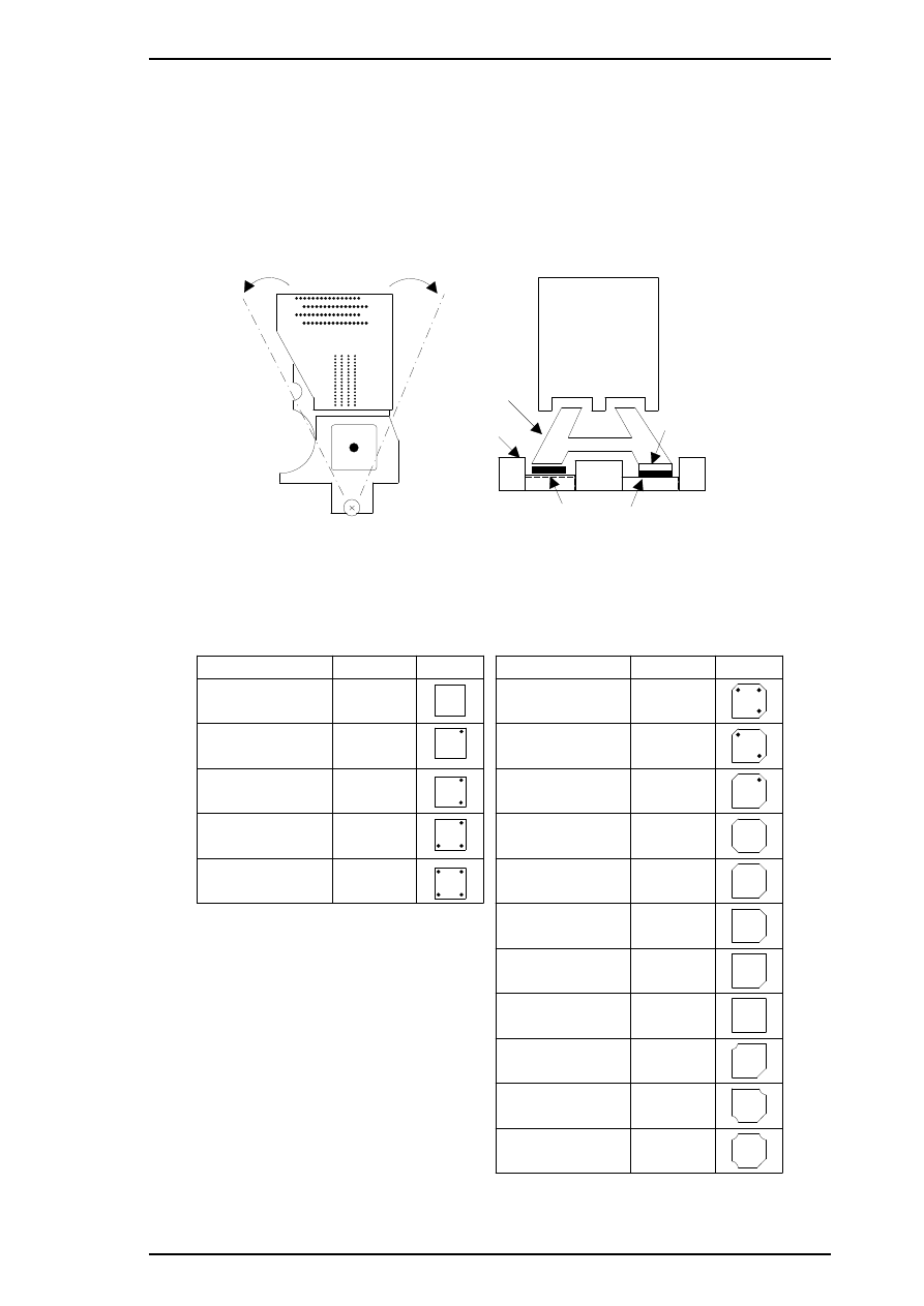
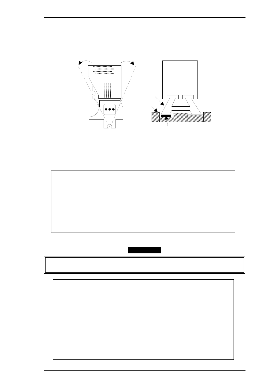
4.1.3 Black Head Angle Adjustment
The black head angle adjustment is required when the black head is replaced or disassembled. If this
adjustment is not correct, a white banding problem may occur, or color head timing may not match black
head timing. The following figure illustrates the black head angle adjustment. The black head angle is
adjusted with linear and angular spacers. A linear spacer is attached to both sides of the head base, and an
angular spacer is attached only to the right side of the head base. Spacers for the black head come in different
shapes for the thickness needed. The following figure shows the relationship between the shape and thickness.
Black Head
(Angle Adjustment)
Head Base
Head Carriage
Angular Spacer
Linear Spacer
Figure 4-2. Black Head Angle Adjustment
Angular Spacers ( for Black Head)
angular spacer BK
Spacer Name
Thickness
Sha pe
0.05
0 . 1 0
angular spacer BK-B
angular spacer BK-C
angular spacer BK-D
angular spacer BK-E
0.15
0.20
0.25
linear s pacer K
Spacer Name
Thickness
Sha pe
0. 05
0 . 1 2
0. 19
0. 26
0. 33
Linear Spac ers (O nly for Black Head)
0 .4 7
0 . 5 4
0. 61
0. 68
0 . 7 5
0 .4 0
line ar s pac er J
linear spacer I
linear spacer
linear s pacer B
linear sp acer C
linear sp acer D
line ar s pac er E
linear spacer F
linear spacer G
line ar s pace r H
Figure 4-3. Types of Spacers and Relationship between
Shape and Thickness
Stylus Pro XL+ Service Manual
Adjustment
Rev.A
4-5
1.
Connect the PC to the target printer using a parallel interface cable and turn the printer on.
2.
Load BASIC on the PC, and run the program. You see the following destination select menu.
***** Customer *****
1. EAI, EAI (Latin America), EAL, ESP
2. EDG, EUL, EFS, EIS, EIB, EUL (Northern Europe), EUL (Middle East), EHK
3.
4. JAPAN
5.
6.
7. END
Select Menu
?
3.
Input the number for the destination. Then the main menu appears, as shown below.
CAUTION
If you enter an incorrect number as the destination selection, printer functions are not
guaranteed.
STYLUS Pro XL+ Program : Rev. X
customer :
1. Head VH input
2. Ink consumption counter reset
3. Head angular & linear adjustment
4. Head position check
5. BK. YMC head gap adjustment (head gap center )
6. Bi-D adjustment
(Bi-d center
)
7. Head VH indication
10. Change customer & data / END
0. Cleaning
Select Menu ? ■
4.
Choose “3, Head angular & linear adjustment” by typing
3
and pressing
ENTER
. (The printer prints the
check pattern, along with the sample name. )
CAUTION
❏ When you replace both the black and color heads, always adjust the color head angle first.
The black head angle is based on the color head angle.
❏ After you replace the black head and print the black head angle pattern, you only have
to insert an angular spacer if the pattern is incorrect.
Adjustment
Stylus Pro XL+ Service Manual
4-6
Rev.A
5.
The printer prints a pattern like one in the following sample. Only the nozzles in rows A and D are fired
(making it is easy to see the angle of the black head).
6.
In the figure above, pay attention to position A. (Do not look at position B.)
7.
Using the following flowchart, replace the angular spacer for the black head, which is under the right
linear spacer. The procedure for this replacement is explained beginning with step 7.
8.
Turn the printer power off now.
9.
Manually move the carriage to the center while pressing the carriage lock lever, and remove the two ink
cartridges.
10. Remove the rubber cap covering the head screw at the side of color ink cartridge. Then loosen (but do
not remove) 3 screws. (Refer to Figure 4-6.)
CAUTION
After replacing the spacer, always install new ink cartridges before returning the printer to the
user. During this adjustment, use ink cartridges exclusively for service:
(Monochrome: 1020626, CMY: 1027990 ).
A
B
3-2. BLACK HEAD ANGLE ADJUSTMENT
Figure 4-4. Black Head Angle Adjustment Sample
Position A
Position A
Replace the right
angular spacer with
a thinner one
Look at position A
Replace the right
angular spacer with
a thicker one
Figure 4-5. Spacer Selection Flowchart
Stylus Pro XL+ Service Manual
Adjustment
Rev.A
4-7
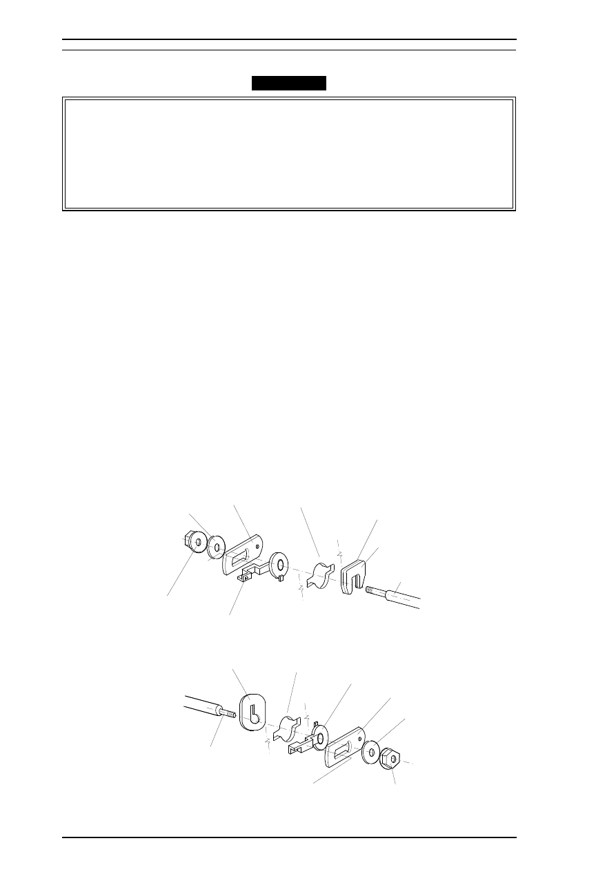
11. Replace the angular spacer for the black head with a new one. (Refer to Figure 4-7.)
(To replace the angular spacer, use tweezers to push the head base toward the rear.)
12. After replacing the angular spacer, reassemble the ink cartridge holder and reinstall the ink cartridges.
Use the BASIC program to verify the angle of the black head. Confirm the angle by performing the
steps 1 to 6 again, and if the angle is wrong, perform the adjustment again until the head angle is correct.
CAUTION
❏ The angular spacers come in five thicknesses. Continue performing this adjustment by
changing the black head spacers until the angle is correct.
❏ When inserting an angular spacer, always place the angular spacer on the linear spacer.
CBB( M3 x1 1 )
Color Ink Cartridge Holder
Rubber Cap
CBB(M 3 x1 1)
CBB(M 3x11 )
Figure 4-6. Removing the Rubber Cap
1. Push
Hea d Ba se
Line ar Spa cers
Platen Gap Adjust Lever
Angular Spacer
Carriage Unit
Black Hea d
2. Replace
Figure 4-7. Angular Spacer Replacement Method
Adjustment
Stylus Pro XL+ Service Manual
4-8
Rev.A
4.1.4 Color Head Angle Adjustment
The color head angle adjustment is required when the color head is replaced or disassembled.
If this
adjustment is not correct, a white banding problem may occur, or the black head timing may not match the
color head timing. The following figure illustrates the color head angle adjustment. The color head angle is
adjusted with the angular spacer. The angular spacer is attached only to the left side of the head base.
1.
Connect the PC to the target printer using a parallel interface cable and turn the printer on.
2.
Load BASIC on the PC, and run the program. You see the following destination select menu.
***** Customer *****
1. EAI, EAI (Latin America), EAL, ESP
2. EDG, EUL, EFS, EIS, EIB, EUL (Northern Europe), EUL (Middle East), EHK
3.
4. JAPAN
5.
6.
7. END
Select Menu
?
3.
Input the number for the destination. Then the main menu appears, as shown below.
CAUTION
If you enter an incorrect number as the destination selection, printer functions are not
guaranteed.
STYLUS Pro XL+ Program : Rev. X
customer :
1. Head VH input
2. Ink consumption counter reset
3. Head angular & linear adjustment
4. Head position check
5. BK. YMC head gap adjustment (head gap center )
6. Bi-D adjustment
(Bi-d center
)
7. Head VH indication
10. Change customer & data / END
0. Cleaning
Select Menu ? ■
Color He ad
Color Head
(Reverse Side)
He a d Ba s e
(Angle Adjustment Concept)
(Spacer Setting Location)
Carriage
An gu lar Spa cer
Figure 4-8. Color Head Angle and Angular Spacer Position
Stylus Pro XL+ Service Manual
Adjustment
Rev.A
4-9
4.
When the main menu appears, choose “3, Head Angle Confirmation Pattern Printing” by typing
3
and
pressing
ENTER
. (The printer prints a check pattern with the sample name.)
CAUTION
When replacing both the black and color heads, always adjust the color head angle first. The
black head angle and the black - color head vertical position adjustments are based on the color
head angle adjustment.
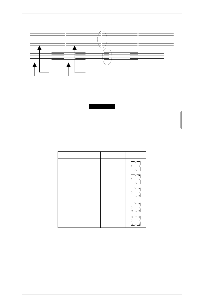
Angular spacers for the color head come in five thicknesses, each having its own shape. The following figure
shows the relationship between the shape and thickness. Since the color head is not equipped with a linear
spacer, the angle adjustment is decided only by the angular spacer (specifically designed for the color head),
which is placed under the left side of the head base.
5.
In Figure 4-9, pay attention to the position of A and B while you reset the left angular spacer. The
replacement procedure is explained beginning in step 6.
6.
Turn off the printer now.
3 -1 YMC HEAD ANGUL AR
Ma g en ta
Ma ge nta
Cya n
C y a n
A
B
Figure 4-9. Color Head Angle Confirmation Sample
Angular Spacers (For Color Head)
angular s pacer YMC
Spacer Name
Thickness
Shape
0 . 3 0
0 . 3 5
a n g u la r sp a c e r YMC - B
angular spacer YM C- C
angular spacer YM C- D
angular s pacer Y MC-E
0 . 4 0
0 . 4 5
0 . 5 0
Figure 4-10. Relationship between the Shape and Thickness
Adjustment
Stylus Pro XL+ Service Manual
4-10
Rev.A
7.
Move the carriage to the center manually, and loosen (but do not remove) the screw securing the color
head to the carriage.
8.
Remove the rubber cap covering the head screw at one side of color ink cartridge. Then loosen (but do
not remove) 3 screws. (Refer to the Figure 4-9.)
9.
Replace the angular spacer on the left side with a new one, referring to the figure below. (Replace the
angular spacer using tweezers to push the head base toward the rear.)
10. Rerun the BASIC program and choose “3, Head Angle Confirmation Pattern Printing” again by typing
3
and pressing
ENTER
. Then verify that the confirmation sample is correct.
11. If the sample is incorrect, repeat steps 6-10 until the upper lines in the sample are aligned with one
another and the lower lines in the sample are exactly equidistant to one another (as shown at B in Figure
4-11).
12. When you complete this adjustment, turn off the printer.
Position A, B
Position A, B
Replace the right
angular spacer
with a thicker one
Replace the right
angular spacer
with a thinner one
(A)
(B)
(A)
(B)
Look at
positions A, B
Figure 4-11. Spacer Selection
1
2
Carriage Unit
Base Head
Paper Gap Adjust Lever
Spacer Angular
(one side only)
Color Head
P u s h
Re p la ce
Figure 4-12. YMC Angular Spacer Replacement
Stylus Pro XL+ Service Manual
Adjustment
Rev.A
4-11
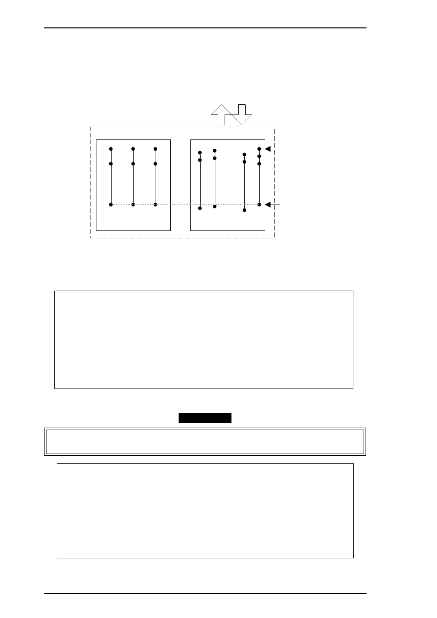
4.1.5 Black - Color Head Vertical Adjustment
This adjustment calibrates the vertical position between the black head and the color head. Align the top
nozzles (both nozzle # 1 on the black head and nozzle # 1 on the color head). You can make this adjustment
by using only the linear spacers for the black head. This adjustment is required when the black head or the
color head is replaced or disassembled. The following figure illustrates this adjustment.
1.
Connect the PC to the target printer using a parallel interface cable and turn the printer on.
2.
Load BASIC on the PC, and run the program. You see the following destination select menu.
***** Customer *****
1. EAI, EAI (Latin America), EAL, ESP
2. EDG, EUL, EFS, EIS, EIB, EUL (Northern Europe), EUL (Middle East), EHK
3.
4. JAPAN
5.
6.
7. END
Select Menu
?
3.
Input the number for the destination. Then the main menu appears, as shown below.
CAUTION
If you enter an incorrect number as the destination selection, printer functions are not
guaranteed.
STYLUS Pro XL+ Program : Rev. X
customer :
1. Head VH input
2. Ink consumption counter reset
3. Head angular & linear adjustment
4. Head position check
5. BK. YMC head gap adjustment (head gap center )
6. Bi-D adjustment
(Bi-d center
)
7. Head VH indication
M
agent
a
C
y
an
Y
e
llo
w
#1
#2
#16
Color Head
Vertical Position
#1
#2
#4
#5
#6
#3
#8
#9
#61
#62
#63
#64
#7
Black Head
Carriage Unit
Adjust
Vertical Position
Figure 4-13. Black - Color Head Vertical Adjustment
Adjustment
Stylus Pro XL+ Service Manual
4-12
Rev.A
10. Change customer & data / END
0. Cleaning
Select Menu ? ■
4.
When the main menu appears, choose “3, Head angular & linear adjustment” by typing
3
and pressing
ENTER
. (The printer prints the check pattern, along with the sample name.)
CAUTION
When replacing the black head, always adjust the black head angle first, because the black - color
head vertical adjustment is based upon the black head angle.
5.
In Figure 4-14, the vertical position is correct when both the magenta line and the black line are aligned
(as shown in position
OK (0)
). If the vertical position is correct, turn off the printer. If the black and
magenta lines are not aligned, perform the vertical adjustment as described in steps 6-10.
CAUTION
❏ The number shown in the sample indicates the thickness level compared to the current
linear spacer. (See * .) There are 11 linear spacers with 11 different thicknesses.
❏ The linear spacer is attached by two pieces, one on each side of the head base. Therefore,
when you need to replace one linear spacer, always replace both linear spacers at the
same time.
❏ When replacing the linear spacer, place it under the angular spacer.
*
If necessary, replace the linear spacer. For instance, if your pattern is similar to the pattern
shown under –2, replace the linear spacer with a thinner linear spacer. If your pattern is similar
to the pattern shown under 2, replace the linear spacer with a thicker spacer.
6.
Turn the printer off.
7.
Move the carriage to the center while pressing the carriage lock lever, and remove the two ink cartridges.
8.
Remove the rubber cap that covers a head screw at the side of color ink cartridge, and then loosen (but
do not remove) 3 screws. (Refer to the figure on the next page.)
CAUTION
After replacing the spacer, always install new ink cartridges before returning the printer to the
user. During adjustment, use the ink cartridges exclusively for service (Monochrome: 1020626,
CMY: 1027990 ).
Magenta
B la ck
- 5
- 4
- 3
- 2
- 1
OK(0)
+ 1
+ 2
+ 3
+ 4
+ 5
3 -3 . B L A CK HE A D S P A CE R S E L E CT I O N
Figure 4-14. Linear Spacer Selection Sample
Stylus Pro XL+ Service Manual
Adjustment
Rev.A
4-13
9.
Change the linear spacers (2 spacers for the monochrome head only) with new ones, referring to the
figure below. (Replace linear spacers by using tweezers to push the head base toward the rear.)
10. Rerun the BASIC program, and choose the “Head Vertical Position Confirmation” by typing
3
and
pressing
ENTER
; then confirm that the sample print is correct. If the sample is incorrect, change the
thickness of the linear spacer and perform this adjustment again until the two black and magenta lines
are aligned at the position “
OK (0)
."”
11. When you complete this adjustment, exit the BASIC program and turn off the printer.
2
Push
Carriage Unit
Linear Spacers x 2
Head Base
Platen Gap Adjust Lever
(Linear Spacer Replac em ent Position)
Angu la r Spa ce r
Replace
1
Figure 4-15. Linear Spacer Replacement Method
Adjustment
Stylus Pro XL+ Service Manual
4-14
Rev.A
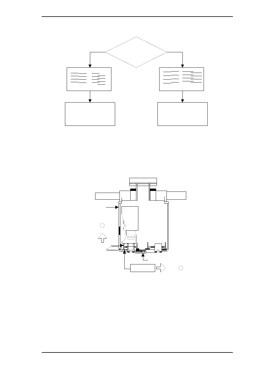
4.1.6 Head Gap Adjustment (Black and Color Head)
The head gap adjustment is required when the printer mechanism, main board, or printhead (board) is
replaced or disassembled. This adjustment calibrates the head drive timing between the black and color head.
If this adjustment is not made, the vertical alignment will not be completed.
1.
Connect the PC to the target printer using a parallel interface cable and turn the printer on.
2.
Load BASIC on the PC, and run the program. You see the following destination select menu.
***** Customer *****
1. EAI, EAI (Latin America), EAL, ESP
2. EDG, EUL, EFS, EIS, EIB, EUL (Northern Europe), EUL (Middle East), EHK
3.
4. JAPAN
5.
6.
7. END
Select Menu
?
3.
Input the number for the destination. Then the main menu appears, as shown below.
CAUTION
If you enter an incorrect number as the destination selection, printer functions are not
guaranteed.
STYLUS Pro XL+ Program : Rev. X
customer :
1. Head VH input
2. Ink consumption counter reset
3. Head angular & linear adjustment
4. Head position check
5. BK. YMC head gap adjustment (head gap center )
6. Bi-D adjustment
(Bi-d center
)
7. Head VH indication
10. Change customer & data / END
0. Cleaning
Select Menu ? ■
4.
When the main menu appears, choose “5, BK. YMC head gap adjustment” by typing
5
and pressing
ENTER
. (The printer prints a check pattern sample with a sample compensation value. The printer prints
a sample like the one shown in the following figure.)
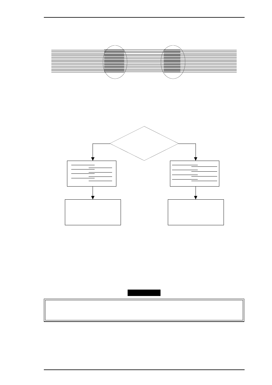
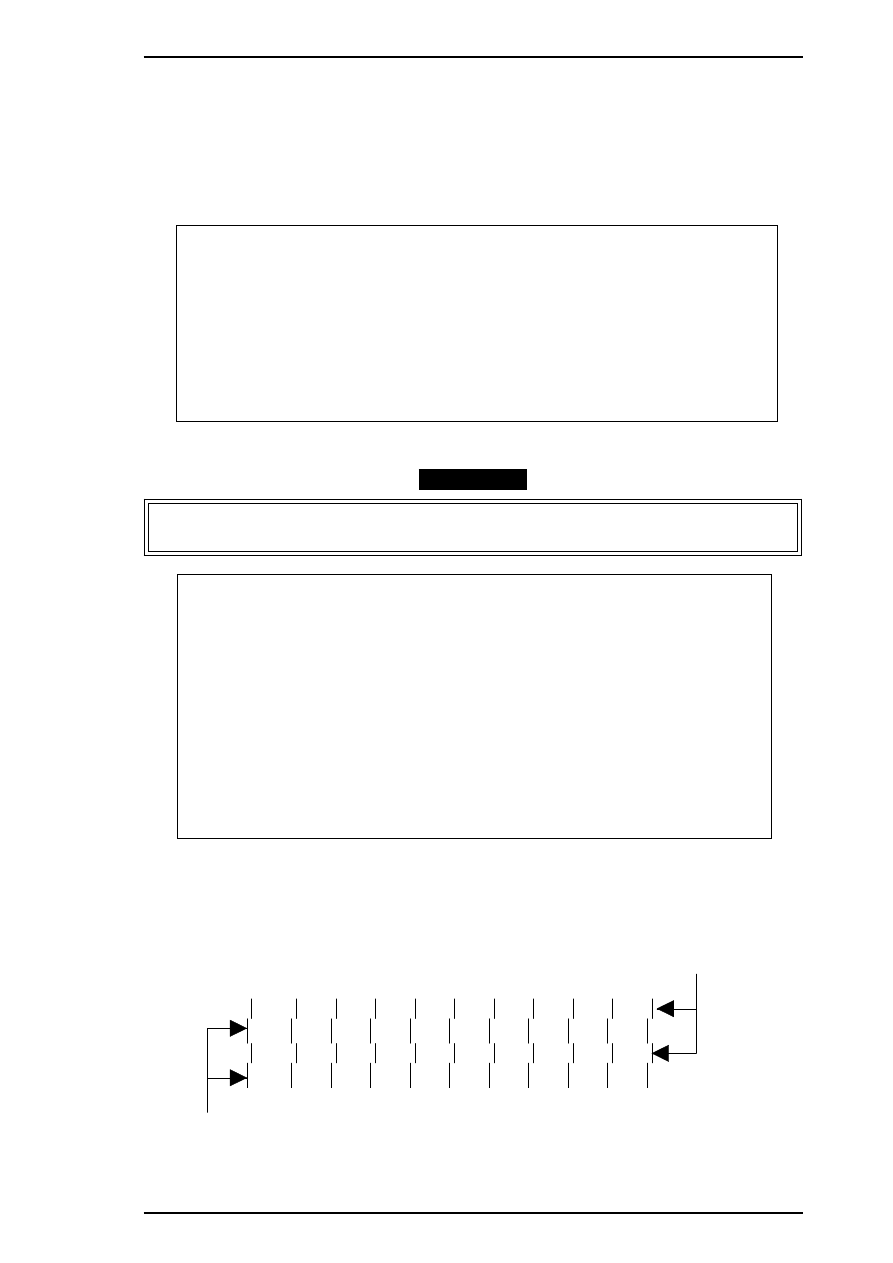
HEAD GAP ADJUST NO . X
Black Line
Color (Magenta) Line
Figure 4-16. Head Gap Adjustment Sample
Stylus Pro XL+ Service Manual
Adjustment
Rev.A
4-15
The adjustment value input menu appears as shown:
INPUT ADJUST No. (IF OK INPUT Y)? ■
adjust
range
(from –32 to 32)
5.
If the sample print is not vertically aligned for both odd-numbered lines (black lines) and
even-numbered lines (magenta lines), enter a compensation value in the range from
−
32 to +32.
❏ Positive compensation value: Shifts the 2nd line to the left
❏ Negative compensation value: Shifts the 2nd line to the right
When both the black and magenta lines are vertically aligned, input Y or y, and press
ENTER
. This
returns you to the main menu.
6.
When the main menu appears, choose “10, Change customer & data / END” by typing
10
and
Enter
.
(This returns you the destination setting menu.)
7.
Choose “7, END” by typing
7
and pressing ENTER to quit the adjustment program.
CAUTION
Settings have not yet been written to the EEPROM. Turn off the printer immediately after the
adjustments.
8.
Turn off the printer.
Adjustment
Stylus Pro XL+ Service Manual
4-16
Rev.A
4.1.7 Bi-D (Bidirectional Printing) Alignment Adjustment
The bidirectional alignment is required when the printer mechanism, main board, or printhead (board) is
replaced. Performing this adjustment determines a compensation value to rectify any deviation in the print
position. This deviation could be caused by different print speeds, which are due to tolerances in the
mechanical components, or to differences in print timing between odd-numbered lines and even-numbered
lines in bidirectional printing. The printer stores the compensation data in the EEPROM on the C184 MAIN
board and refers to this data when performing bidirectional printing.
1.
Connect the PC to the target printer using a parallel interface cable and turn the printer on.
2.
Load BASIC on the PC, and run the program. You see the following destination select menu.
***** Customer *****
1. EAI, EAI (Latin America), EAL, ESP
2. EDG, EUL, EFS, EIS, EIB, EUL (Northern Europe), EUL (Middle East), EHK
3.
4. JAPAN
5.
6.
7. END
Select Menu
?
3.
Input the number for the destination. Then the main menu appears, as shown below.
CAUTION
If you enter an incorrect number as the destination selection, printer functions are not
guaranteed.
STYLUS Pro XL+ Program : Rev. X
customer :
1. Head VH input
2. Ink consumption counter reset
3. Head angular & linear adjustment
4. Head position check
5. BK. YMC head gap adjustment (head gap center )
6. Bi-D adjustment
(Bi-d center
)
7. Head VH indication
10. Change customer & data / END
0. Cleaning
Select Menu ? ■
4.
When the main menu appears, choose “6, Bi-D Adjustment” by typing
6
and pressing
ENTER
. (The
printer prints a check pattern with a sample compensation value. The next menu appears on the display.)
INPUT ADJUST No. (If OK INPUT Y)? ■
720 DPI adjust range ( from –30 to 30)
Stylus Pro XL+ Service Manual
Adjustment
Rev.A
4-17
5.
If the sample print is not vertically aligned for both the odd-numbered and even-numbered lines, enter a
compensation value in the range from –30 to +30.
❏ Positive compensation value: Shifts the 2nd line to the left
❏ Negative compensation value: Shifts the 2nd line to the right
When the sample print becomes vertically aligned for both lines, press
Y
and
ENTER
; then the printer
prints out the current Bi- D setting pattern, and this returns you to the 360 DPI Bi-d adjustment mode.
6.
Adjust the 360 DPI Bi-d setting mode in the same way as 720 dpi Bi-D adjustment.
7.
If you have finished the 360 dpi Bi-d adjustment, choose “10, END” by typing
10
and pressing
ENTER
. (The destination setting menu appears on the display again.)
8.
Choose “7, END” by typing
7
and pressing ENTER to quit the adjustment program.
CAUTION
Settings have not been written to the EEPROM yet. Turn off the printer immediately after the
adjustments.
9.
Turn off the printer.
Adjustment
Stylus Pro XL+ Service Manual
4-18
Rev.A
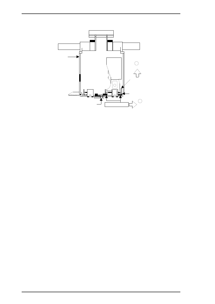
4.1.8 Platen Gap Adjustment
This adjustment is required when the carriage unit is replaced or removed from the printer mechanism. Adjust
the distance between the printhead nose and the paper surface to 1.1 mm.
1.
Attach a thickness gauge (commercially available) to the left side adjustment position on the paper guide
plate, as shown in the figure below, so that one side hooks the paper feed pinch roller unit.
2.
Move the carriage unit manually onto the thickness gauge.
Table 4-2. Gap and Adjustment Direction
Gap between Head Nose and Gauge Surface
Left Bushing
Right Bushing
Narrow
CW
CCW
Spread
CCW
CW
3.
Rotate the parallelism adjustment bushing, attached to the left and right ends of the carriage guide shaft,
when the black and color printheads contact the thickness gauge.
4.
After attaching the printheads to the gauge surface, verify that the gap between the carriage roller and the
front frame is less than 0.04 mm. (See Figure 4-18.)
5.
Attach the 1.1 mm thickness gauge to the right side adjustment position on the paper guide plate, as
shown below, so that one side hooks the paper feed pinch roller unit.
B u sh i n g
Right Adjustment Position
Left Adjustment Position
Paper Guide Plate
P u mp Un it
Front Frame
Thickn ess Gau ge
Thickn ess Gau ge
Platen
Attach the thickness gauge
under the PF pinch roller unit.
F R O N T
Plat en
PF Pinch Roller
Unit
Fron t Frame
Pa pe r Gu id e
Tension Roller
Thickness Gauge
Attachment Point
Figure 4-17. Adjusting the Paper Gap
Stylus Pro XL+ Service Manual
Adjustment
Rev.A
4-19
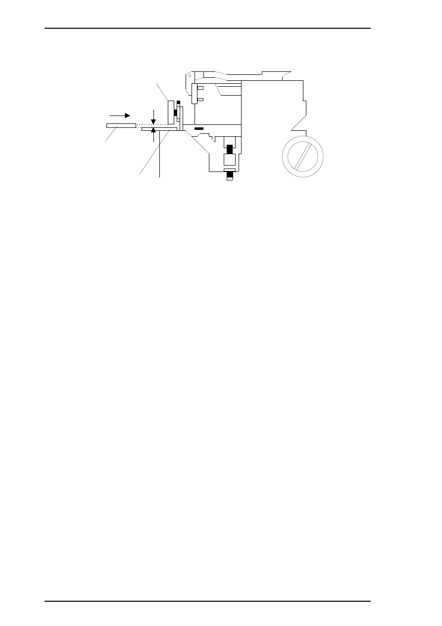
Note:
When checking the gap between the carriage roller and the front frame, use the thickness
gauge or the paper guide plate. If the gap is correct the gauge cannot be installed into the
gap. If the gap is incorrect, the gauge can be inserted in the gap.
6.
Move the carriage manually to the right adjustment position and repeat steps 3, 4 and 5 referring to
Figures 4-17 and 4-18.
G AP
0.04 mm
Thickness
Gauge
Eject Frame
Carriage Roller
Figure 4-18. Confirming the Gap
Adjustment
Stylus Pro XL+ Service Manual
4-20
Rev.A
4.1.9 Ink Consumption Counter Reset Operation
This operation is required when the ink cartridge is replaced. Usually, this operation is performed by the panel
operation. But if you perform this operation, you can reset the ink consumption counter value at any time.
1.
Connect the PC to the target printer using a parallel interface cable and turn the printer on.
2.
Load BASIC on the PC, and run the program. You see the following destination select menu.
***** Customer *****
1. EAI, EAI (Latin America), EAL, ESP
2. EDG, EUL, EFS, EIS, EIB, EUL (Northern Europe), EUL (Middle East), EHK
3.
4. JAPAN
5.
6.
7. END
Select Menu
?
3.
Input the number for the destination. Then the main menu appears, as shown below.
CAUTION
If you enter an incorrect number as the destination selection, printer functions are not
guaranteed.
STYLUS Pro XL+ Program : Rev. X
customer :
1. Head VH input
2. Ink consumption counter reset
3. Head angular & linear adjustment
4. Head position check
5. BK. YMC head gap adjustment (head gap center )
6. Bi-D adjustment
(Bi-d center
)
7. Head VH indication
10. Change customer & data / END
0. Cleaning
Select Menu ? ■
4.
When the main menu appears, choose “2, Ink consumption counter reset” by typing
2
and pressing
ENTER
. This resets the internal timer. The following message then appears.
Ink Counter Reset
Black Ink Counter Reset only ——- 1
Color Ink Counter Reset only ——- 2
Both Ink Counters Reset
——- 3
Quit Ink Counter Reset
——- 4
Select No.
5.
Choose and type the selection number. This returns you to the main menu.
Stylus Pro XL+ Service Manual
Adjustment
Rev.A
4-21
4.1.10 Head Cleaning Function
This function performs the compulsory ink charging to the printer head in order to check using the service
tool for ink charging.
1.
Connect the PC to the target printer using a parallel interface cable and turn the printer on.
2.
Load BASIC on the PC, and run the program. You see the following destination select menu.
***** Customer *****
1. EAI, EAI (Latin America), EAL, ESP
2. EDG, EUL, EFS, EIS, EIB, EUL (Northern Europe), EUL (Middle East), EHK
3.
4. JAPAN
5.
6.
7. END
Select Menu
?
3.
Input the number for the destination. Then the main menu appears, as shown below.
STYLUS Pro XL+ Program : Rev. X
customer :
1. Head VH input
2. Ink consumption counter reset
3. Head angular & linear adjustment
4. Head position check
5. BK. YMC head gap adjustment (head gap center )
6. Bi-D adjustment
(Bi-d center
)
7. Head VH indication
10. Change customer & data / END
0. Cleaning
Select Menu ? ■
4.
When the main menu appears, choose “0, Cleaning” by typing
0
and pressing
ENTER
. This resets the
internal timer. The following message then appears.
Ink Counter Reset
Black Ink counter Reset only ——- 1
Color Ink Counter Reset only ——- 2
Both Ink Counter Reset
——- 3
Quit Ink Counter Reset
——- 4
Select No.
5.
Choose and type the selection number. This returns you to main menu.
CAUTION
If you perform this function on the same ink cartridge repeatedly, the ink life of this cartridge
becomes shorter than normal.
Adjustment
Stylus Pro XL+ Service Manual
4-22
Rev.A
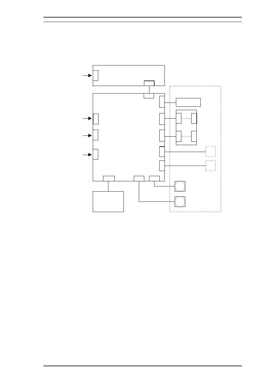
A.1 CONNECTOR SUMMARY
The figure below shows the interconnection of major components of the Stylus Color Pro XL+.
CN
1
C N 2
CN
1
C N 5
C
N
1
1
C
N
9
C
N
8
C N 7
C N 6
C N 1 0
CN
CN
C
N
CN
2
Type B I/F
(Option)
CN
3
RS- 422
Serial I/F
C
N
1
2
C
N
Parallel I/F
C
N
1
3
C1 37 P NL
AC Inlet
ASF Plunger
Printhead Unit
HP Sensor
CR Sensor
C 1 8 4 M AI N
C1 37 P SB /P SE
RF Motor
CR Motor
Printer M echan ism
Figure A-1. Interconnection of major components
STYLUS PRO XL+ Service Manual
Appendix
Rev.A
A-1
Table A-1. Connector Summary
Board
Location
Pins
Description
C164 MAIN
CN1
36
Centronics parallel I/F
CN2
36
Type B parallel I/F
CN3
8
RS-422 serial I/F
CN5
6
Power supply from PS board
CN6
5
Carriage motor phase output
CN7
5
PF/PM motor phase output
CN8
2
Paper end sensor
CN9
3
Carriage home position sensor
CN10
20
Control panel (to C137 PNL)
CN11
22
Black head nozzle selector and common driver
CN12
22
Color head nozzle selector and common driver
C137 PSB/PSE
CN1
2
AC inlet (L/N)
CN2
8
DC output (+5 V / +35 V)
C137 PNL
CN1
20
(to C164 MAIN)
Appendix
STYLUS PRO XL+ Service Manual
A-2
Rev.A
Table A-2. Connector Pin Assignments — CN1
Pin
I/O
Name
Description
1
I
STB / Host Clk
STROBE signal / Clock signal (Host)
2-9
I
DATA1-8
Data strobe signal
10
O
ACK / Ptr Clk
ACK signal / Clock signal (Printer)
11
O
BUSY / Ptr Busy (Data
Bit-3, 7)
Busy signal / Printer busy signal and reverse
channel transfer data bits 3, 7
12
O
PE / Ack Data Req
(Data Bit-2, 6)
Paper end signal / ACK data request signal
and reverse channel transfer data bits 2, 6
13
O
SLCT / Xflag
(Data Bit-1, 5)
Printer select signal / X-flag signal and reverse
channel data bit 1, 5
14
I
AFXT / Host Busy
Auto line feed signal / Host busy signal
15
—
NC
Not connected
16
—
GND
Ground
17
—
FG
Frame ground
18
O
Logic-H
Pulled up to +5 V through 3.9K
Ω
/ A HIGH
signal indicates that all other signals sourced
by the peripheral are in valid status
19-30
—
GND
Ground
31
I
INIT
INIT signal
32
O
ERR / Data Avail
(Data Bit-0, 4)
Error signal / Data available signal and reverse
channel transfer data bit 0, 4
33
—
GND
Ground
34
—
NC
Not connected
35
O
+5 V
Pulled up to +5 V through 3.3K
Ω
36
I
SLIN / 1284-Active
Not used / 1284 active signal
STYLUS PRO XL+ Service Manual
Appendix
Rev.A
A-3
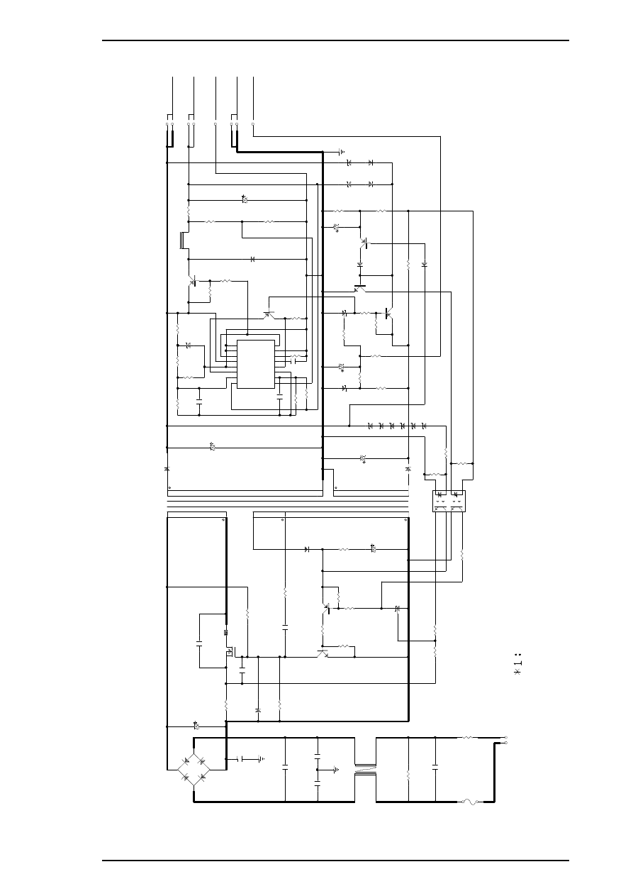
2
3
2
T
1
P
T
-4
9
D
5
1
F
5
K
Q
1
0
0
1
1
1
3
2
4
D
B
1
D
2
S
B
A
6
0
C
1
1
2
2
0
U
/2
0
0
V
R
1
2
0
.6
8
/2
W
B
1
Q
1
K
1
3
5
1
*1
C
1
5
3
9
0
0
P
/1
.2
K
V
3
C
5
1
3
3
0
0
U
/5
0
V
R
5
8
2
0
0
K
R
8
1
8
4
.5
K
R
5
9
4
.7
5
K
C
5
9
1
0
0
0
P
Q
5
1
A
1
4
6
9
Z
D
5
5
H
Z
S
6
A
1
L
R
6
0
1
0
K
R
6
1
2
0
0
R
5
1
4
7
0
/2
W
L
5
1
L
H
L
1
0
T
B
1
5
1
K
R
5
3
0
.2
2
/2
W
R
6
4
3
0
0
+
5
V
/0
.8
A
+
3
5
V
/0
.4
A
6
7
8
4
5
G
L
G
P
1
C
N
2
P
S
C
R
6
5
6
.2
K
C
5
4
1
0
0
0
U
/1
0
V
Q
8
4
D
T
A
1
2
4
E
S
D
5
5
2
1
D
Q
0
4
R
8
2
1
0
K
R
6
3
2
K
+
I
1
1
- I 1
2
F B
3
D T C
4
C T
5
R T
6
G N D
7
C 1
8
+
I
2
1 6
- I 2
1 5
R O
1 4
O C
1 3
V C C
1 2
C 2
1 1
E 2
1 0
E 1
9
IC
5
1
T
L
4
9
4
C
5
8
0
.0
1
U
C
8
1
2
2
0
0
P
R
6
6
2
0
0
K
4
5
C
1
3
0
.0
1
U
R
1
1
3
0
0
/0
.5
W
R
1
8
2
4
0
K
/0
.5
W
F
G
C
8
1
0
0
0
P
C
1
4
2
2
0
0
P
R
1
9
2
0
K
D
2
1
1
E
Q
S
0
4
C
2
0
.1
U
C
3
2
2
0
0
P
1
2
3
4
L
1
E
L
F
1
8
D
2
9
0
G
F
G
C
4
2
2
0
0
P
R
1
4
5
1
0
R
1
3
4
.7
K
R
1
5
5
1
0
R
1
6
2
7
0
Q
2
C
4
4
0
8
Q
3
A
1
0
1
5
D
1
1
1
E
Q
S
0
6
1
0
9
R
3
2
R
6
7
2
K
C
5
5
2
2
0
U
/5
0
V
R
8
4
2
0
0
K
C
8
2
3
3
0
U
/6
.3
V
Z
D
8
6
H
Z
S
6
A
1
L
Q
8
2
D
T
C
1
2
4
E
S
D
8
4
G
M
B
0
1
2
1
3
IC
8
1
T
L
4
3
1
R
8
5
1
K
R
8
6
4
.7
K
Z
D
5
2
H
Z
S
3
6
-3
Z
D
5
3
H
Z
S
7
B
2
C
5
6
3
3
U
/3
5
V
R
5
5
1
5
K
Q
8
1
D
T
A
1
2
4
E
S
F
G
D
8
2
G
M
B
0
1
D
8
1
G
M
B
0
1
R
5
4
1
0
K
D
8
3
G
M
B
0
1
Q
8
3
A
1
0
1
5
R
8
7
5
1
0
R
8
8
1
0
0
R
6
9
5
1
0
Z
D
8
1
Z
D
8
2
Z
D
8
3
Z
D
8
4
R
8
3
5
1
K
Z
D
5
1
H
Z
S
7
B
3
Z
D
8
5
H
Z
S
5
C
3
X
5
C
1
2
1
0
0
U
/2
5
V
D
5
2
A
G
0
1
Z
8
6
2
1
3
IC
1
T
L
4
3
1
R
1
3
0
0
K
/0
.5
W
C
1
0
.2
2
U
F
1
2
.5
A
1
2
5
V
o
r
2
5
0
V
R
2
3
.9
/5
W
R
2
1
1
0
K
R
2
0
3
K
1
2
3
4
8
7
6
5
P
C
1
P
S
2
5
0
1
-2
R
3
1
2
K
R
6
8
3
K
R
5
7
2
4
0
R
5
6
1
6
0
L
N
1
0
0
-1
2
0
V
A
C
1
2
C
N
1
H
e
a
ts
in
k
0
Figure A-4. C137 PSB Board Circuit Diagram
STYLUS PRO XL+ Service Manual
Appendix
Rev.A
A-9
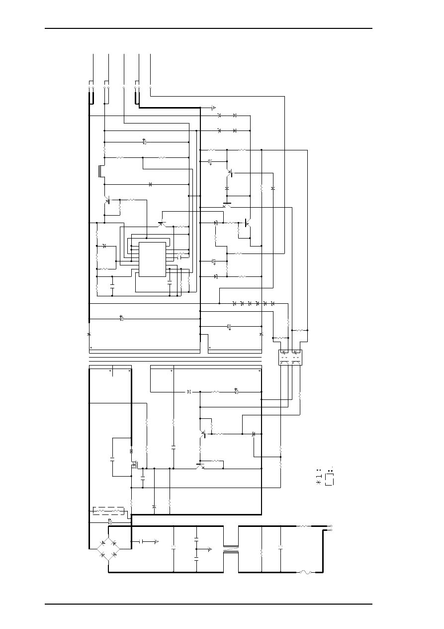
2
3
T
1
P
T
-5
0
D
5
1
F
5
K
Q
1
0
0
1
1
1
1
3
2
4
D
B
1
D
2
S
B
A
6
0
C
1
1
5
6
U
/4
0
0
V
R
1
2
1
.5
/2
W
R
3
2
R
3
3
B
1
Q
1
K
1
6
0
3
*1
C
1
5
1
0
0
0
P
/1
.5
K
V
3
2
C
5
1
3
3
0
0
U
/5
0
V
R
5
8
2
0
0
K
R
8
1
8
4
.5
K
R
5
9
4
.7
5
K
C
5
9
1
0
0
0
P
Q
5
1
A
1
4
6
9
Z
D
5
5
H
Z
S
6
A
1
L
R
6
0
1
0
K
R
6
1
2
0
0
R
5
1
4
7
0
/2
W
L
5
1
L
H
L
1
0
T
B
1
5
1
K
R
5
3
0
.2
2
/2
W
R
6
4
3
0
0
+
5
V
/0
.8
A
+
3
5
V
/0
.4
A
6
7
8
4
5
G
L
G
P
1
C
N
2
P
S
C
R
6
5
6
.2
K
C
5
4
1
0
0
0
U
/1
0
V
Q
8
4
D
T
A
1
2
4
E
S
D
5
5
2
1
D
Q
0
4
R
8
2
1
0
K
R
6
3
2
K
+
I
1
1
- I
1
2
F B
3
D T C
4
C T
5
R T
6
G N D
7
C 1
8
+
I
2
1 6
- I
2
1 5
R O
1 4
O C
1 3
V C C
1 2
C 2
1 1
E 2
1 0
E 1
9
IC
5
1
T
L
4
9
4
C
5
8
0
.0
1
U
C
8
1
2
2
0
0
P
R
6
6
2
0
0
K
4
5
C
1
3
4
7
0
0
P
R
1
1
5
6
0
/0
.5
W
R
2
8
3
0
0
K
/0
.5
W
R
1
8
/Z
D
1
3
0
0
K
/0
.5
W
F
G
C
8
1
0
0
0
P
C
1
4
1
0
0
0
P
R
1
9
2
0
K
D
2
1
1
E
Q
S
0
4
C
2
0
.1
U
C
3
2
2
0
0
P
1
2
3
4
L
1
E
L
F
1
8
D
2
9
0
C
F
G
C
4
2
2
0
0
P
R
1
4
5
1
0
R
1
3
4
.7
K
R
1
5
5
1
0
R
1
6
2
7
0
Q
2
C
4
4
0
8
Q
3 A1
0
1
5
D
1
1
1
E
Q
S
0
6
1
0
9
R
3
2
R
6
7
2
K
C
5
5
2
2
0
U
/5
0
V
R
8
4
2
0
0
K
C
8
2
3
3
0
U
/6
.3
V
Z
D
8
6
H
Z
S
6
A
1
L
Q
8
2
D
T
C
1
2
4
E
S
D
8
4
G
M
B
0
1
2
1
3
IC
8
1
T
L
4
3
1
R
8
5
1
K
R
8
6
4
.7
K
Z
D
5
2
H
Z
S
3
6
-3
Z
D
5
3
H
Z
S
7
B
2
C
5
6
3
3
U
/3
5
V
R
5
5
1
5
K
Q
8
1
D
T
A
1
2
4
E
S
F
G
D
8
2
G
M
B
0
1
D
8
1
G
M
B
0
1
R
5
4
1
0
K
D
8
3
G
M
B
0
1
Q
8
3
A
1
0
1
5
R
8
7
5
1
0
R
8
8
1
0
0
R
6
9
5
1
0
Z
D
8
1
Z
D
8
2
Z
D
8
3
Z
D
8
4
R
8
3
5
1
K
Z
D
8
5
H
Z
S
5
C
3
X
5
Z
D
5
1
H
Z
S
7
B
3
C
1
2
1
0
0
U
/2
5
V
D
5
2
A
G
0
1
Z
8
6
2
1
3
IC
1
T
L
4
3
1
R
1
5
1
0
K
/0
.5
W
C
1
0
.2
2
U
F
1 T1
.2
5
A
H
/2
5
0
V
R
2
1
0
/5
W
R
2
1
1
0
K
R
2
0
3
K
R
5
7
2
4
0
R
3
1
2
K
R
6
8
3
K
1
2
3
4
8
7
6
5
P
C
1
P
S
2
5
6
1
L
1
-2
-V
R
5
6
1
6
0
L
N
2
2
0
-2
4
0
V
A
C
1
2
C
N
1
H
e
a
ts
in
k
N
o
t
m
o
u
n
te
d
0
Figure A-5. C137 PSE Board Circuit Diagram
Appendix
STYLUS PRO XL+ Service Manual
A-10
Rev.A
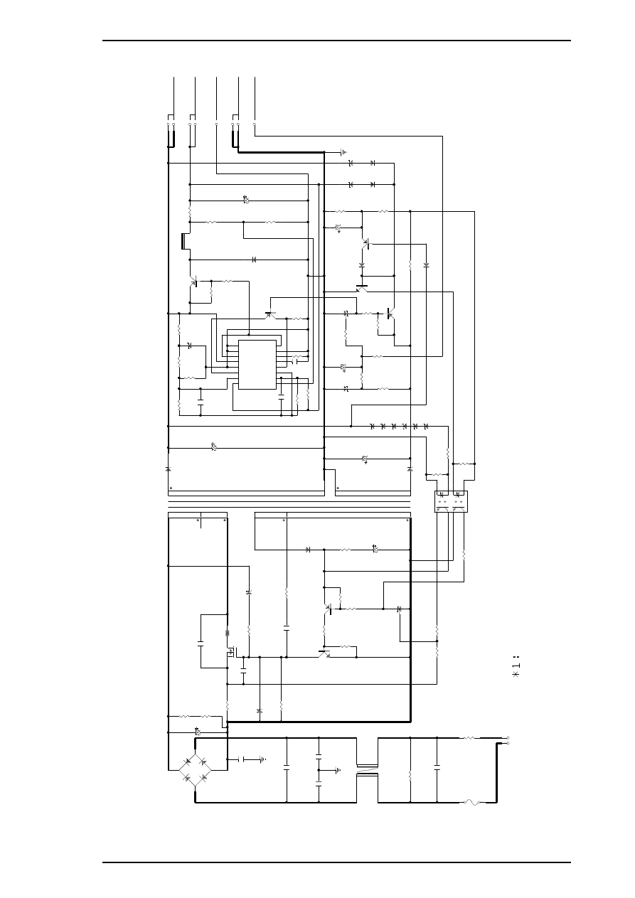
2
3
T
1
P
T
-5
0
D
5
1
F
5
K
Q
1
0
0
1
1
1
1
3
2
4
D
B
1
D
2
S
B
A
6
0
C
1
1
5
6
U
/4
0
0
V
R
1
2
1
.5
/2
W
R
3
3
3
9
0
K
/0
.5
W
R
3
4
3
9
0
K
/0
.5
W
B
1
Q
1
K
1
6
0
3
*1
C
1
5
1
0
0
0
P
/1
.5
K
V
3
2
C
5
1
3
3
0
0
U
/5
0
V
R
5
8
2
0
0
K
R
8
1
8
4
.5
K
C
5
9
1
0
0
0
P
R
5
9
4
.7
5
K
Q
5
1
A
1
4
6
9
Z
D
5
5
H
Z
S
6
A
1
L
R
6
0
1
0
K
R
6
1
2
0
0
R
5
1
4
7
0
/2
W
L
5
1
L
H
L
1
0
T
B
1
5
1
K
R
5
3
0
.2
2
/2
W
R
6
4
3
0
0
+
5
V
/0
.8
A
+
3
5
V
/0
.4
A
6
7
8
4
5
G
L
G
P
1
C
N
2
P
S
C
R
6
5
6
.2
K
C
5
4
1
0
0
0
U
/1
0
V
Q
8
4
D
T
A
1
2
4
E
S
D
5
5
2
1
D
Q
0
4
R
8
2
1
0
K
R
6
3
2
K
+
I
1
1
- I
1
2
F B
3
D T C
4
C T
5
R T
6
G N D
7
C 1
8
+
I
2
1 6
- I
2
1 5
R
O
1 4
O C
1 3
V C C
1 2
C 2
1 1
E 2
1 0
E 1
9
IC
5
1
T
L
4
9
4
C
5
8
0
.0
1
U
C
8
1
2
2
0
0
P
R
6
6
2
0
0
K
4
5
C
1
3
4
7
0
0
P
R
1
1
5
6
0
/0
.5
W
R
2
8
3
9
0
K
/0
.5
W
R
1
8
/Z
D
1
R
D
1
2
0
E
F
G
C
8
1
0
0
0
P
C
1
4
1
0
0
0
P
R
1
9
1
3
K
D
2
1
1
E
Q
S
0
4
C
2
0
.1
U
C
3
2
2
0
0
P
1
2
3
4
L
1
E
L
F
1
8
D
2
9
0
C
F
G
C
4
2
2
0
0
P
R
1
4
5
1
0
R
1
3
4
.7
K
R
1
5
5
1
0
R
1
6
2
7
0
Q
2
C
4
4
0
8
Q
3 A
1
0
1
5
D
1
1
1
E
Q
S
0
6
1
0
9
R
3
2
R
6
7
2
K
C
5
5
2
2
0
U
/5
0
V
R
8
4
2
0
0
K
C
8
2
3
3
0
U
/6
.3
V
Z
D
8
6
H
Z
S
6
A
1
L
Q
8
2
D
T
C
1
2
4
E
S
D
8
4
G
M
B
0
1
2
1
3
IC
8
1
T
L
4
3
1
R
8
5
1
K
R
8
6
4
.7
K
Z
D
5
2
H
Z
S
3
6
-3
Z
D
5
3
H
Z
S
7
B
2
C
5
6
3
3
U
/3
5
V
R
5
5
1
5
K
Q
8
1
D
T
A
1
2
4
E
S
F
G
D
8
2
G
M
B
0
1
D
8
1
G
M
B
0
1
R
5
4
1
0
K
D
8
3
G
M
B
0
1
Q
8
3
A
1
0
1
5
R
8
7
5
1
0
R
8
8
1
0
0
R
6
9
5
1
0
Z
D
8
1
Z
D
8
2
Z
D
8
3
Z
D
8
4
R
8
3
5
1
K
Z
D
8
5
H
Z
S
5
C
3
X
5
Z
D
5
1
H
Z
S
7
B
3
C
1
2
1
0
0
U
/2
5
V
D
5
2
A
G
0
1
Z
8
6
2
1
3
IC
1
T
L
4
3
1
R
1
5
1
0
K
/0
.5
W
C
1
0
.2
2
U
F
1
T
1
.2
5
A
H
/2
5
0
V
R
2
1
0
/5
W
R
2
1
1
0
K
R
2
0
3
K
R
5
7
2
4
0
R
3
1
2
K
R
6
8
3
K
1
2
3
4
8
7
6
5
P
C
1
P
S
2
5
6
1
L
1
-2
-V
R
5
6
1
6
0
L
N
2
2
0
-2
4
0
V
A
C
1
2
C
N
1
H
e
a
ts
in
k
0
Figure A-6. C137 PSE (Korea) Board Circuit Diagram
STYLUS PRO XL+ Service Manual
Appendix
Rev.A
A-11
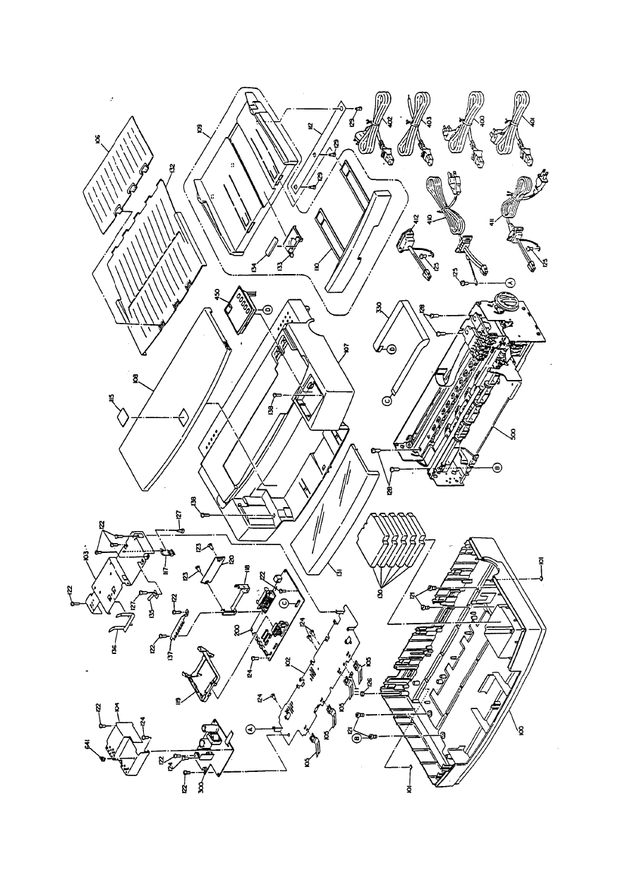

EPSON
Document Outline
- Front Cover
- Preface
- Revision Sheet
- 1.1 Product Description - Features
- 1.2 Specifications
- 1.3 Interface Specifications
- 1.4 Operations
- 2.1 Operating Principles
- 3.1 Disassembley and Assembley
- 4.1 Adjustment
- Appendix
- Back Cover
Wyszukiwarka
Podobne podstrony:
Epson Stylus Color 460 Service Manual
Epson Stylus Color 300 Service Manual
Epson Stylus Pro 9000 Auto Take Up Reel Unit Manual
Epson Stylus Color 700 Stylus Color EX Service Manual
Epson DLQ 3000 (upgrade model) Service Manual
ZOKES PRO SERVICE MANUAL
hplj 5p 6p service manual vhnlwmi5rxab6ao6bivsrdhllvztpnnomgxi2ma vhnlwmi5rxab6ao6bivsrdhllvztpnnomg
Oberheim Prommer Service Manual
Korg SQ 10 Service Manual
MAC1500 service manual
Kyocera Universal Feeder UF 1 Service Manual
Proview RA783 LCD Service Manual
indesit witp82euy Service Manual
więcej podobnych podstron