

2
Motorola GPS Products
M12 Oncore User’s Guide Supplement
Revision 1.0 01/25/00
M12 Oncore
User’s Guide Supplement
6. RF Characteristics of Receiver

3
Motorola GPS Products
M12 Oncore User’s Guide Supplement
Revision 1.0 01/25/00
Receiver Architecture
• 12 parallel channels
• L1 1575.42 MHz
• C/A code (1.023 MHz chip rate)
• Code plus carrier tracking (carrier aided tracking)
Tracking Capability
• 12 simultaneous satellites
Dynamics
• Velocity: 515 m/s (1000 knots); >515 m/s at altitudes < 18,000 m
• Acceleration: 4 g
• Jerk: 5 m/s
3
• Vibration: 7.7G per Military Standard 810E
Acquisition Time
• <15 s typical TTFF - Hot (current almanac, position, time, ephemeris)
(Time To First Fix, TTFF)
• <45 s typical TTFF - Warm (current almanac, position and time)
• <70 s typical TTFF - Cold (No stored information)
• <1.0 s internal reacquisition
Positioning Accuracy
• 100 meters 2dRMS with SA as per DoD specification
• Less than 25 meters, SEP without SA
Timing Accuracy (1PPS)
• < 500 ns with SA on
Datum
• WGS-84
• One user definable datum
I/O Messages
• Latitude, longitude, height, velocity, heading, time
• Motorola binary protocol at 9600 baud
• NMEA 0183 at 4800 baud (GGA, GLL, GSA, GSV, RMC, VTG, ZDA)
• Software selectable output rate (continuous or poll)
• 3 V digital logic interface
• Second COM port for RTCM input
Power Requirements
• 2.8 to 3.2 Vdc; 50 mVp-p ripple (max)
"Keep-Alive" BATT Power
• External 1.8 Vdc to 3.2 Vdc, 5µA (typical @2.7 Vdc @ +25°C)
Power Consumption
• <0.225 W @ 3 V without antenna
Dimensions
• 40.0 x 60.0 x 10.0 mm [1.57 x 2.36 x 0.39 in.]
Weight
• Receiver 25 g (0.9 oz.)
Connectors
• Power/Data: 10 pin (2x5) unshrouded male header on 0.050 inch
centers (available in right angle or straight configuration)
• RF: right angle MMCX female (subminiature snap-on)
Antenna
• Active micro strip patch Antenna Module
• Powered by Receiver Module at selectable 3 or 5 V
Antenna to Receiver
• Single coaxial cable with 6 dB maximum loss at L1 (active antenna)
Interconnection • Antenna
Sense
Circuit
• Antenna gain range 10 - 26 dB
Operating Temperature
• -40˚C to +85˚C
Storage Temperature
• -40˚ to 105˚C
Humidity
• 95% over dry bulb range of +38˚C to+85˚C
Altitude
•
18,000 m (60,000 ft.) maximum
• > 18,000 m (60,000 ft.) for velocities < 515m/s (1000 knots)
Standard Features
• Motorola DGPS corrections at 9600 baud on COM port one
• RTCM SC-104 input Type 1 and Type 9 messages for DGPS at
2400, 4800 or 9600 baud on COM port two
• NMEA 0138 output
• Inverse DGPS support
Optional features
• Lithium battery backup
General
Characteristics
Performance
Characteristics
Serial
Communication
Electrical
Characteristics
Environmental
Characteristics
Miscellaneous

4
Motorola GPS Products
M12 Oncore User’s Guide Supplement
Revision 1.0 01/25/00
2. Basic Description
2.1 Receiver architecture
Channels
12 parallel
Frequency
1575.42 MHz
Code
C/A
Tracking
Carrier aided
2.2 Description
The highly integrated single board GPS receiver module is optimized specifically for automotive
applications. The GPS receiver tracks the
constellation of satellites. The satellite
signals received by an active antenna are tracked with 12 parallel channels of L1, C/A code then
downconverted to an IF frequency and digitally processed to obtain a full navigation solution of
position, velocity, time and heading. The solution is then sent over the serial link via the 10-pin
connector.
5
Motorola GPS Products
M12 Oncore User’s Guide Supplement
Revision 1.0 01/25/00
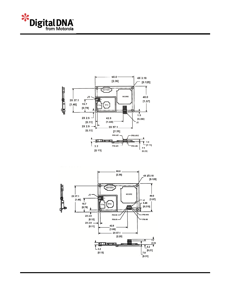
3. Mechanical
3.1 Mechanical Drawings
3.1.1
M12 Oncore with right angle power/data connector
3.1.2
M12 Oncore with straight power/data connector

6
Motorola GPS Products
M12 Oncore User’s Guide Supplement
Revision 1.0 01/25/00
3.2
Size
Dimensions
40.0 x 60.0 x 10.0 mm
3.3
Weight
< 25 g
3.4
Connectors
Power/Data
Straight: Samtec, FW-05-03-L-D-156-156, 10-pin
Right Angle: Samtec, ASP62522-01-M, 10-pin
Antenna RF
Sub-miniature MMCX connector type
4.
Environmental
4.1
Temperature
Operating
-40°C to +85°C
Storage
-40°C to +105°C
4.2
Relative humidity
Operating
95% over dry bulb range of +38°C to +85°C
4.3
Vibration
0.04 G
2
/Hz, 20 Hz to 1000 Hz
7.7 G per Military Standard 810E
5.
Electrical
5.1
Pin Outputs
Pin #
Signal
Description
1
TTL TXD1
Transmit 3 V logic
2
TTL RXD1
Receive 3 V logic
3
+3.0 V PWR
+3 V regulated main power
4
1 PPS
One pulse per second signal
5
GROUND
Ground (receiver)
6
BATTERY
Externally applied backup power (1.8 to 3.2 V)
7
Reserved
Not currently used
8
RTCM IN
RTCM input only
9
ANTENNA VOLTAGE
3 V or 5 V antenna input voltage
10
Reserved
Not currently used

7
Motorola GPS Products
M12 Oncore User’s Guide Supplement
Revision 1.0 01/25/00
5.2
Main power
Voltage
2.8 to 3.2 Vdc regulated
50 mV maximum peak-to-peak ripple
Power
0.225 W maximum (without antenna)
5.3
Backup power
Voltage
1.8 V to 3.2 V
Current
5 mA typical @ 2.7 V
Retention
Backup power retains date, time, position, satellite data,
oscillator learning table and operating mode
5.4
Antenna feed power out of RF connector
Voltage
2.7 V to 3.2 V over current range for 3 V antenna
Current
15 mA to 80 mA
Flags set in serial data when limits exceeded
5.5
1PPS signal definition
Level
0 V to 3 V
Time mark
Rising edge
Width
200 ms typical
5.6
Serial I/O signal definition
Levels
0 V to 3 V, active low
Baud rate
9600 (Motorola Binary)
4800 (NMEA)
Parity
None
Data bits
8
Start/stop bits
1
6.
RF Characteristics of Receiver
6.1
Dynamic range
27 dB
6.2
Saturation
-110 dBm

8
Motorola GPS Products
M12 Oncore User’s Guide Supplement
Revision 1.0 01/25/00
7.
RF Requirements for Antenna
7.1
General
Frequency
1575.42 MHz (L1)
Bandwidth
± 1.023 MHz
Polarization
Right hand circular
Impedance
50
Ω
7.2
Gain requirement
10 dB to 26 dB (at receiver input)
7.3
Gain Pattern
+0 dBic minimum at zenith
-10 dBic minimum at 0° elevation
7.4
Noise figure
1.8 dB typical
2.2 dB maximum
7.5
VSWR
1.5:1 typical
2.5:1 maximum
7.6
Axial ratio
3 dB typical at zenith
6 dB maximum at zenith
7.7
1 dB compression point
-14 dBm typical (at antenna output)
7.8
3 dB frequency bandwidth
45 MHz maximum
7.9
25 dB frequency rejection
± 95 MHz
7.10
Ground plane
15 x 15 cm recommended
7.11
Power
Voltage
2.8 V to 3.2 V, or 4.75 V to 5.25 V
3.0 V typical, or 5.0 V typical
Current
15 mA typical
25 mA maximum
7.12
Temperature
Operating
-40°C to +85°C
Storage
-40°C to +100°C

9
Motorola GPS Products
M12 Oncore User’s Guide Supplement
Revision 1.0 01/25/00
8.
Performance
8.1
Accuracy
Position
25 m SEP without SA
100 m 2DRMS (95%) with SA
1 to 5 m typical in differential mode
Altitude
156 m RMS (95%)
Velocity
0.02 m/s without SA
Time pulse
UTC ± 500 ns with SA on
8.2
Dynamic limits
Velocity
515 m/s maximum at altitudes > 18000 m
Altitude
-1000 m minimum
18000 m maximum at velocities > 515 m/s
Acceleration
4 G maximum
Jerk
5 m/s
3
maximum
8.3
Startup time (TTFF)
Hot (date, time, position, almanac, ephemeris)
15 s
Warm (date, time, position, almanac, olt)
45 s
Cold (no stored information)
70 s
8.4
Reacquisition time
After 60 s obstruction
3.5 s
Internal
< 1.0 s
8.5
RFI
Jamming resistance
Resistant to narrow band CW jamming at the
receiver input of +20dBm at less than 1525
MHz and greater than 1625 MHz for loss of
lock with a signal input of –130 dBm
Burnout protection
Protected from damage by RF signals at
frequencies100 MHz or more from L1 with
received power up to 1 W at the antenna
8.6
EMI
Radiated
Complies with Class B, Part 15 of FCC rules
Conducted
Complies with European CE requirements
Tested to IEC 801-4 spec for fast transients
at 500 V, 5/50 ns, 5 kHz

10
Motorola GPS Products
M12 Oncore User’s Guide Supplement
Revision 1.0 01/25/00
9.
Features
9.1
Differential operation
Motorola binary corrections on TTL RXD1 (pin 2) at 9600 baud
RTCM SC-104 Type 1 and Type 9 corrections on TTL RXD2 (pin 8) at 2400 or 9600 baud
9.2
NMEA 0183 output
NMEA 0183
Output on TTL TX1 at 4800 baud
Messages supported
GGA, GLL, GSA, GSV, RMC, VTG, ZDA
9.3
User definable datum
One user definable datum may be defined using the @@Ap command. The default datum is
WGS-84.
9.4
Antenna sense circuit
The M12 Oncore receiver is capable of detecting the presence of an antenna. The receiver
utilizes an antenna sense circuit, which can detect under current (open) and over current
(shorted or exceeding maximum limit) conditions. The status of the antenna circuit is
reported in the Position/Status/Data Message (@@Ha), the Short Position Message (@@Hb)
and the Self-Test Message (@@Ia).
The antenna sense circuit is useful for verifying that the antenna is properly connected to the
receiver and is drawing the proper amount of current. The antenna sense status should be
checked after installation and monitored regularly.
Undercurrent indication < 8 mA
Overcurrent indication
> 80 mA
9.5
Real time clock
The real-time clock (RTC) is a standard feature on the M12 Oncore. It is used to minimize
the time to first fix (TTFF). The date and time will be retained in the RTC if battery backup
power is applied when main power is off.
The user has two options regarding time initialization:
1)
Set the date and time BEFORE the receiver acquires any satellites
2)
Let the receiver automatically set the date and time AFTER acquiring the first satellite
Note: The date and time cannot be manually set while the receiver is tracking satellites.
Without battery backup, the receiver will start-up with a default time of 12:00:00. To obtain a
faster time to first fix, the time, date and GMT offset should be initialized if both the main
power and battery backup power have been disconnected.

11
Motorola GPS Products
M12 Oncore User’s Guide Supplement
Revision 1.0 01/25/00
10.
Serial I/O Messages
10.1
Solution
Update rate
1 Hz maximum (Selectable 1/s – 1/255s)
Latency
< 1 s
Reported
Position, velocity, time, satellite status, receiver status,
antenna status
Reference
WGS-84 or user defined datum
10.2
Resolution
Latitude/longitude
1 milliarcsecond
Height
0.01 m
Velocity
0.01 m/s
Heading
0.1°
Time
1 ns
10.3
Solution quality indicators
Receiver status
3D, 2D, propagation, acquisition
Geometry
HDOP when in 2D mode
PDOP when in 3D mode
Satellite status
C/No (dB)
Flag indicating satellite tracking status
Flag indicating satellite is used in solution
10.4
Initialization
Startup mode
Acquisition based on information available
Battery backup provided
No initialization required
No battery backup
Receiver will be in default condition, entering date, time,
position and almanac will speed up acquisition process
Default condition
No serial messages active unless there is a power-on self-
test failure
10.5
RTCM Commands
The M12 Oncore accepts RTCM SC-104 Type 1 and Type 9 messages. The messages are
input on the second communications port (pin 8) at a user selectable baud rate of 2400,
4800 or 9600. The RTCM messages are buffered and processed independently from the
primary communications port.

12
Motorola GPS Products
M12 Oncore User’s Guide Supplement
Revision 1.0 01/25/00
10.6 Motorola binary I/O command list
Motorola binary commands can be used to initialize, configure, control and monitor the GPS receiver.
The Motorola binary commands are supported on the primary communications port at 9600 baud.
The commands supported by the M12 Oncore are listed in the table below, and detailed command
descriptions are provided in alphabetical order by binary command on subsequent pages.
Function
Description
Binary Controller
Supplement
Command
Command
Page #
Satellite Set Mask Angle @@Ag mask 14
Receiver Satellite Ignore List @@Am ignore 16
Setup Select Datum @@Ao datum 18
Setup Set User Datum @@Ap udatum 20
Setup Atmospheric Correction Mode @@Aq ion 22
1PPS Position-Hold Position @@As php 24
Setup Altitude-Hold Height @@Au ahp 26
Time Time Mode @@Aw utc 28
1PPS 1PPS Cable Delay @@Az ppsdelay 30
Position Position Lock Parameters @@AM lockp 32
Setup Velocity Filter @@AN filter 34
Setup RTCM Port Mode @@AO p2baud 36
Position Position Filter Select @@AQ pfilter 38
Position Position Lock Select @@AS locke 40
Satellite Visible Satellite Status @@Bb vis 42
Almanac Almanac Status @@Bd alm 44
Almanac Almanac Data Output @@Be almout 46
Ephemeris Ephemeris Data Input @@Bf ephin 48
Almanac Almanac Data Input @@Cb almin 50
Time UTC Offset Status @@Bo utcoff 52
Receiver UTC/Ionospheric Data Output @@Bp utcion 54
DGPS Pseudorange Correction Input @@Ce n/a 56
Receiver Set-to-Defaults @@Cf default 58
NMEA Switch to NMEA @@Ci ioformat 60
Receiver Receiver ID @@Cj id 62
Receiver UTC/Ionospheric Data Input @@Co n/a 64
Position ASCII Position Message @@Eq as8 66
Position Combined Position @@Ga compo 68
Time Combined
1PPS 1PPS Control @@Gc ppscon 72
Position Position Control @@Gd holdcon 74
Time Leap Second Status @@Gj leap12 76
Setup ID Tag @@Gk vin 78
Position Position/Status/Data Message (12Ch) @@Ha ps12 80
Position Short Position Message (12Ch) @@Hb psd 86
Setup Self-Test Message (12Ch) @@Ia selftest12 90
Receiver System Power-On Failure @@Sz n/a 92

13
Motorola GPS Products
M12 Oncore User’s Guide Supplement
Revision 1.0 01/25/00
Page intentionally left blank.

SATELLITE MASK ANGLE
The GPS receiver will attempt to track satellites for which the elevation angle is
greater than the satellite mask angle. This parameter allows the user to control the
elevation angle that was used for this decision.
Range:
0 to 89 degrees
Default value:
0 degrees
14
Motorola GPS Products
M12 Oncore User’s Guide Supplement
Revision 1.0 01/25/00

15
Motorola GPS Products
M12 Oncore User’s Guide Supplement
Revision 1.0 01/25/00
SATELLITE MASK ANGLE
Motorola Binary Format
• Poll current mask angle:
@@Ag
xC<CR><LF>
x
1 out of range byte
$ff
C
checksum
Message length: 8 bytes
• Change current mask angle:
@@Ag
dC<CR><LF>
d
degrees
0 .. 89
C
checksum
Message length: 8 bytes
• To either command:
@@Ag
dC<CR><LF>
d
degrees
0 .. 89
C
checksum
Message length: 8 bytes
Input Command
Response Message

SATELLITE IGNORE LIST
It is useful to have the flexibility to delete particular satellite identification numbers
(SVIDs) from the selection process. The GPS receiver includes, in its list of satellites
to track, all satellites that are healthy and in the almanac. The user can elect to
ignore particular satellites in the almanac by issuing an Ignore Satellite Command.
In addition, the user can restore any previously ignored satellite IDs by issuing an
Include Satellite Command. This command also affects the satellite Alert-Planning
settings. Satellites that have been removed by this command are not included in the
produced Alert-Planning output. The user may notice a delay between issuing this
command and the actual removal or inclusion of particular satellites.
Default value:
All satellite SVIDs included.
16
Motorola GPS Products
M12 Oncore User’s Guide Supplement
Revision 1.0 01/25/00

Response Message
Input Command
SATELLITE IGNORE LIST
Motorola Binary Format
• Send Current Satellite Ignore List:
@@Am
xxxxxC<CR><LF>
xxxxx
5 bytes
all hex 00
C
checksum
Message Length: 12 bytes
• Change Satellite Ignore List:
@@Am
kssssC<CR><LF>
k
00 fixed binary constant
ssss
32 bit binary field. Each bit represents one SVID.
(msb = SVID 32, lsb = SVID 1)
1 = Ignore
0 = Include
C
checksum
Message Length: 12 bytes
• To either command:
@@Am
kssssC<CR><LF>
k
00 fixed binary constant
ssss
32 bit binary field. Each bit represents one SVID.
(msb = SVID 32, lsb = SVID 1)
1 = Ignore
0 = Include
C
checksum
Message Length: 12 bytes
17
Motorola GPS Products
M12 Oncore User’s Guide Supplement
Revision 1.0 01/25/00

18
Motorola GPS Products
M12 Oncore User’s Guide Supplement
Revision 1.0 01/25/00
SELECT DATUM
The GPS receiver has one predefined datum in its internal memory and one user
definable datum. The datums are referenced by an ID number. The predefined
datum is number 49 and the user defined datum is number 50. The user instructs
the GPS receiver which datum to use by sending the Select Datum command. The
command contains the ID number of the desired datum and the GPS receiver
returns the response message which gives the user the ability to validate that the
input command was accepted. The user can instruct the GPS receiver to use the
user defined datum by sending the Select Datum command set to 50.
Default datum:
WGS-84 (ID code 49)

SELECT DATUM
Motorola Binary Format
• Poll current datum ID code:
@@Ao
xC<CR><LF>
x
1 out of range byte
$ff
C
checksum
Message length: 8 bytes
• Change current datum ID code:
@@Ao
dC<CR><LF>
d
datum ID
49 or 50
C
checksum
Message length: 8 bytes
• To either command:
@@Ap
dsssffiiffffxxyyzzC<CR><LF>
d
datum ID
49 or 50
sssff
semi-major axis (m)
sss
integer part
6,000,000 .. 7,000,000
ff
fractional part
0 .. 999 (0.0 .. 0.999)
iiffff
inverse flattening
ii
integer part
285 .. 305
ffff
fractional part
0 .. 999,999,999 (0.0 .. 0.999999999)
xx
delta X (0.1 m)
-32,768 .. 32,767 (-3276.8 .. 3276.7)
yy
delta Y (0.1 m)
-32,768 .. 32,767 (-3276.8 .. 3276.7)
zz
delta Z (0.1 m)
-32,768 .. 32,767 (-3276.8 .. 3276.7)
C checksum
Message length: 25 bytes
Input Command
19
Motorola GPS Products
M12 Oncore User’s Guide Supplement
Revision 1.0 01/25/00
Response Message

20
Motorola GPS Products
M12 Oncore User’s Guide Supplement
Revision 1.0 01/25/00
SET USER DATUM
The GPS receiver has one user defined datum stored as ID number 50. The User
Datum command allows the user to define the constants used for a custom datum.
A datum is defined by a semi-major axis, an inverse flattening constant, and an
offset from the center of mass of the earth given as delta-X, delta-Y, and delta-Z
parameters.
Default values:
WGS-84 parameters

Motorola GPS Products
M12 Oncore User’s Guide Supplement
Revision 1.0 01/25/00
SET USER DATUM
Motorola Binary Format
• Poll current user defined datum parameters:
@@Ap
dxxxxxxxxxxxxxxxxxC<CR><LF>
d
desired user datum
50
xxxxxxxxxxxxxxxxx
17 bytes
all hex 00
C
checksum
Message length: 25 bytes
• Change current user defined datum parameters:
@@Ap
dsssffiiffffxxyyzzC<CR><LF>
d
datum ID
50
sssff
semi-major axis (m)
sss integer part
6,000,000 .. 7,000,000
ff
fractional part
0 .. 999 (0.0 .. 0.999)
iiffff
inverse flattening
ii
integer part
285 .. 305
ffff fractional part
0 .. 999,999,999 (0.0 .. 0.999999999)
xx
delta X (0.1 m)
-32,768 .. 32,767 (-3276.8 .. 3276.7)
yy
delta Y (0.1 m)
-32,768 .. 32,767 (-3276.8 .. 3276.7)
zz
delta Z (0.1 m)
-32,768 .. 32,767 (-3276.8 .. 3276.7)
C checksum
Message length: 25 bytes
• To either command:
@@Ap
dsssffiiffffxxyyzzC<CR><LF>
d
datum ID
50
sssff
semi-major axis (m)
sss
integer part
6,000,000 .. 7,000,000
ff
fractional part
0 .. 999 (0.0 .. 0.999)
iiffff
inverse flattening
ii
integer part
285 .. 305
ffff
fractional part
0 .. 999,999,999 (0.0 .. 0.999999999)
xx
delta X (0.1 m)
-32,768 .. 32,767 (-3276.8 .. 3276.7)
yy
delta Y (0.1 m)
-32,768 .. 32,767 (-3276.8 .. 3276.7)
zz
delta Z (0.1 m)
-32,768 .. 32,767 (-3276.8 .. 3276.7)
C checksum
Message length: 25 bytes
Input Command
Response Message
21

ATMOSPHERIC CORRECTION MODE
The user has the flexibility of turning the GPS ionospheric and/or tropospheric
correction models on or off. The models do a reasonable job of taking out the range
error induced by the earth’s ionosphere and troposphere by using algorithms and
parameters transmitted to the users by the satellites. For some applications, such as
differential systems, the atmospheric models should be disabled since the differential
corrections include the atmospheric errors.
Default modes:
Ionospheric model enabled
Tropospheric model disabled
Motorola GPS Products
M12 Oncore User’s Guide Supplement
Revision 1.0 01/25/00
22

23
Motorola GPS Products
M12 Oncore User’s Guide Supplement
Revision 1.0 01/25/00
ATMOSPHERIC CORRECTION MODE
Motorola Binary Format
• Poll current Atmospheric Correction Mode:
@@Aq
xC<CR><LF>
x
1 out of range byte
$ff
C
checksum
Message length: 8 bytes
• Change current Atmospheric Correction Mode:
@@Aq
sC<CR><LF>
s
selection
0 = both models disabled
1 = ionospheric model only enabled
2 = tropospheric model only enabled
3 = both models enabled
C
checksum
Message length: 8 bytes
• To either command:
@@Aq
sC<CR><LF>
s
selection
0 = both models disabled
1 = ionospheric model only enabled
2 = tropospheric model only enabled
3 = both models enabled
C
checksum
Message length: 8 bytes
Input Command
Response Message

POSITION-HOLD POSITION
The user can specify receiver coordinates for timing applications to increase the
timing accuracy. This command is used to enter the position to be held. Note that
this command will only be executed if the Position Control (@@Gd) position hold is
disabled.
The position to be held is specified in the same units and referenced to the same
datum (WGS 84) as the initial position coordinates of latitude, longitude and height
(to the same resolution). The height parameter is referenced to the GPS reference
ellipsoid. Note that all three parameters must be specified. The valid ranges of each
parameter are the same as those specified in the Combined Position Message
(@@Ga).
Default values:
Latitude = 0° (Equator)
Longitude = 0° (Grenwich Meridian)
Height = 0 m (GPS Height)
24
Motorola GPS Products
M12 Oncore User’s Guide Supplement
Revision 1.0 01/25/00

Input Command
POSITION-HOLD POSITION
Motorola Binary Format
• Poll current Position-Hold Position:
@@As
xxxxxxxxxxxxxC<CR><LF>
xxxxxxxxxxxx
13 out of range bytes
$7fffffff7fffffff7fffffffff
C
checksum
Message length: 20 bytes
• Change current Position-Hold Position:
@@As
lllloooohhhhtC<CR><LF>
llll
latitude in mas
-324,000,000 .. 324,000,000 (-90° .. 90°)
oooo
longitude in mas
-648,000,000 .. 648,000,000 (-180° .. 180°)
hhhh
height in cm
-100000 .. 1,800,000 (-1,000.00 .. 18,000.00 m)
t
height type
0 = GPS height
C
checksum
Message length: 20 bytes
• To either command:
@@As
lllloooohhhhtC<CR><LF>
llll
latitude in mas
-324,000,000 .. 324,000,000 (-90° .. 90°)
oooo
longitude in mas
-648,000,000 .. 648,000,000 (-180° ..180°)
hhhh
height in cm
-100,000 .. 1,800,000 (-1,000.00 .. 18,000.00 m)
t
height type
0 = GPS height
C
checksum
Message length: 20 bytes
NOTE: Position-Hold Position is enabled and disabled using the Position Control command
(@@Gd).
25
Motorola GPS Products
M12 Oncore User’s Guide Supplement
Revision 1.0 01/25/00
Response Message

ALTITUDE-HOLD HEIGHT
The user can specify the receiver height for manual altitude-hold applications. Use
the Position Control (@@Gd) command to enable or disable the altitude-hold
feature. The Altitude-Hold Height is specified in units of meters to a resolution of
0.01 meters. The height is referenced to the GPS reference ellipsoid. The datum for
the height is the one selected using the Select Datum command.
Default value:
0 m
26
Motorola GPS Products
M12 Oncore User’s Guide Supplement
Revision 1.0 01/25/00

ALTITUDE-HOLD HEIGHT
Motorola Binary Format
• Poll current Altitude-Hold Height:
@@Au
xxxxxC<CR><LF>
xxxx
5 out of range bytes
$7ffffffff
C
checksum
Message length: 12 bytes
• Change current Altitude-Hold Height:
@@Au
hhhhtC<CR><LF>
hhhh
height in cm
-100,000 .. 1,800,000 (-1000.00 to + 18,000.00 m)
t
height type
0 = GPS height
C
checksum
Message length: 12 bytes
• To either command:
@@Au
hhhhtC<CR><LF>
hhhh
height in cm
-100,000 .. 1,800,000 (-1000.00 to + 18,000.00 m)
t
height type
0 = GPS height
C
checksum
Message length: 12 bytes
Note: Altitude-Hold Height is enable and disabled using the Position Control command
(@@Gd).
Input Command
Response Message
27
Motorola GPS Products
M12 Oncore User’s Guide Supplement
Revision 1.0 01/25/00

TIME MODE
This command selects the type of time (either GPS or UTC) to be output in the
Position/Status/Data and Short Position Messages. The Time Mode command will be used to
determine the synchronization point for the 1PPS timing pulse.
Note that if the receiver does not have the UTC parameters portion of the almanac, UTC will
be output as being equal to GPS time and a flag denoting the lack of UTC parameters will be
set in the Position/Status/Data message (@@Ha).
The receiver will have the UTC parameters once an almanac has been downloaded from the
satellites.
Default mode:
UTC
28
Motorola GPS Products
M12 Oncore User’s Guide Supplement
Revision 1.0 01/25/00

TIME MODE
Motorola Binary Format
• Poll current Time Mode:
@@Aw
xC<CR><LF>
x
1 out of range byte
$ff
C
checksum
Message length: 8 bytes
• Change current Time Mode:
@@Aw
mC<CR><LF>
m
mode
0 = GPS
1 = UTC
C
checksum
Message length: 8 bytes
• To either command:
@@Aw
mC<CR><LF>
m
mode
0 = GPS
1 = UTC
C
checksum
Message length: 8 bytes
29
Motorola GPS Products
M12 Oncore User’s Guide Supplement
Revision 1.0 01/25/00
Input Command
Response Message

1PPS CABLE DELAY
The GPS receiver outputs a 1PPS signal, the rising edge of which is placed at the top
of the GPS or UTC one second tic mark epoch as specified by the Time Mode. The
1PPS Cable Delay command allows the user to offset the 1PPS time mark in one
nanosecond increments relative to the measurement epoch.
This parameter instructs the GPS receiver to output the 1PPS output pulse earlier in
time to compensate for antenna cable delay. Up to one millisecond of equivalent
cable delay can be removed. Zero cable delay is set for a zero-length antenna cable.
The user should consult a cable data book for the delay per foot for the particular
antenna cable used in order to compute the total cable delay needed for a particular
installation.
This parameter also allows the user to adjust the position of the 1PPS to compensate
for other system delays.
Range:
0.000 to 0.000999999 s
Default value:
0.000 s
Resolution:
1 ns
30
Motorola GPS Products
M12 Oncore User’s Guide Supplement
Revision 1.0 01/25/00

1PPS CABLE DELAY
Motorola Binary Format
• Poll current 1PPS Cable Delay:
@@Az
xxxxC<CR><LF>
xxxx
4 out of range bytes
$ffffffff
C
checksum
Message length: 11 bytes
• Change current 1PPS Cable Delay:
@@Az
ttttC<CR><LF>
tttt
time offset in ns
0 .. 999,999 ns
(0.0 to 0.000999999 s)
C
checksum
Message length: 11 bytes
• To either command:
@@Az
ttttC<CR><LF>
tttt
time offset in ns
0 .. 999,999 ns
(0.0 to 0.000999999 s)
C
checksum
Message length: 11 bytes
Input Command
Response Message
31
Motorola GPS Products
M12 Oncore User’s Guide Supplement
Revision 1.0 01/25/00

POSITION LOCK PARAMETERS
This message allows the user to enter a threshold speed (default 0.5 m/sec) and a
threshold distance (default 100 meters). The position will be locked if the current
speed and distance traveled are both less than their respective thresholds. The
parameters will be remembered through power cycles if battery back-up is provided.
Default values:
Speed threshold = 0.5 m/s
Distance threshold = 100 m
32
Motorola GPS Products
M12 Oncore User’s Guide Supplement
Revision 1.0 01/25/00

POSITION LOCK PARAMETERS
Motorola Binary Format
• Poll Current Position Lock Paramater:
@@AM
xxxxC<CR><LF>
xxxx
4 out of range bytes
$ffffffff
C
checksum
Message Length: 11 bytes
• Change Current Position Lock Paramaters:
@@AM
ifddC<CR><LF>
i
integer part of
Speed threshold
0…255 m/s
f
fractional part of speed
threshold
0…99 cm/s
d
distance threshold
0…65535 m
C
checksum
Message Length: 11 bytes
• To either command:
@@AM
ifddC<CR><LF>
i
integer part of speed
threshold
0…255 m/s
f
fractional part of speed
threshold
0…99 cm/s
d
distance threshold
0…65535 m
C
checksum
Message Length: 11 bytes
Input Command
33
Motorola GPS Products
M12 Oncore User’s Guide Supplement
Revision 1.0 01/25/00
Response Message

VELOCITY FILTER
The Velocity Filter command controls the velocity filtering feature. The velocity filter
is useful in marine applications to filter out some of the wave motion in the reported
velocity.
The filter is a single order alpha filter, where alpha is the value entered by the user
ranging from 10 to 100 in increments of one. Alpha is then used in the filtered
velocity solution representing 10% to 100% of the last calculated velocity, the
remainder of which uses the previously reported velocity. If a value of 10 is entered
for alpha, the maximum filtering will be done. An alpha value this low must be used
with caution; the reported velocity will have extreme latency. An alpha value of 100
will result in no filtering, which is the default alpha value.
Default value:
100
34
Motorola GPS Products
M12 Oncore User’s Guide Supplement
Revision 1.0 01/25/00

VELOCITY FILTER
Motorola Binary Format
• Poll current Velocity Filter parameter:
@@AN
xC<CR><LF>
x
1 out of range byte
$ff
C
checksum
Message length: 8 bytes
• Change current Velocity Filter parameter:
@@AN
fC<CR><LF>
f
filter parameter
10 .. 100 (max. filtering to no filtering)
C
checksum
Message length: 8 bytes
• To either command:
@@AN
fC<CR><LF>
f
filter parameter
10 .. 100 (max. filtering to no filtering)
C
checksum
Message length: 8 bytes
Input Command
35
Motorola GPS Products
M12 Oncore User’s Guide Supplement
Revision 1.0 01/25/00
Response Message

RTCM PORT MODE
This command allows the user to select the baud rate of the RTCM serial input port
(pin 8). The allowable baud rates are 2400, 4800 and 9600. The baud rate of this
secondary port is independent of the status of the primary serial port.
Default mode: 9600 baud
36
Motorola GPS Products
M12 Oncore User’s Guide Supplement
Revision 1.0 01/25/00

RTCM PORT MODE
Motorola Binary Format
• Poll current RTCM Port Mode:
@@AO
bC<CR><LF>
x
1 out of range byte
$ff
C
checksum
Message length: 8 bytes
• Change current RTCM Port Mode:
@@AO
bC<CR><LF>
b
RTCM port baud rate
0 = 9600
1 = 4800
2 = 2400
C
checksum
Message length: 8 bytes
• To either command:
@@AO
bC<CR><LF>
b
RTCM port baud rate
0 = 9600
1 = 4800
2 = 2400
C
checksum
Message length: 8 bytes
37
Motorola GPS Products
M12 Oncore User’s Guide Supplement
Revision 1.0 01/25/00
Input Command
Response Message

POSITION FILTER SELECT
This message enables or disables the position filter. The default value will be filter
enabled. The selection will be remembered through power cycles if battery back-up
is provided.
Default mode: Enabled
38
Motorola GPS Products
M12 Oncore User’s Guide Supplement
Revision 1.0 01/25/00

POSITION FILTER SELECT
Motorola Binary Format
• Poll current Position Filter Selection:
@@AQ
xC<CR><LF>
x
1 out of range byte
$ff
C
checksum
Message Length: 8 bytes
• Change current Position Filter Selection:
@@AQ
sC<CR><LF>
s
selection
0 = Disabled
1 = Enabled
C
checksum
Message Length: 8 bytes
• To either command:
@@AQ
sC<CR><LF>
s
selection
0 = Disabled
1 = Enabled
C
checksum
Message Length: 8 bytes
Input Command
Response Message
39
Motorola GPS Products
M12 Oncore User’s Guide Supplement
Revision 1.0 01/25/00

POSITION LOCK SELECT
This message enables or disables the position lock feature. The default value will be
disabled. The selection will be remembered through power cycles if battery back-up
is provided.
Default mode: Disabled
40
Motorola GPS Products
M12 Oncore User’s Guide Supplement
Revision 1.0 01/25/00

POSITION LOCK SELECT
Motorola Binary Format
• Poll Current Position Lock Selec:
@@AS
xC<CR><LF>
x
1 out of range byte
$ff
C
checksum
Message Length: 8 bytes
• Change Current Position Lock Select:
@@AS
eC<CR><LF>
e
selection
0 = Disabled
1 = Enabled
C
checksum
Message Length: 8 bytes
• To either command:
@@AS
eC<CR><LF>
e
selection
0 = Disabled
1 = Enabled
C
checksum
Message Length: 8 bytes
Response Message
41
Motorola GPS Products
M12 Oncore User’s Guide Supplement
Revision 1.0 01/25/00
Input Command

VISIBLE SATELLITE STATUS
This command requests the results of the most current satellite alert computation.
The response message gives a summary of the satellite visibility status showing the
number of visible satellites, the Doppler frequency and the location of the currently
visible satellites (up to 12 satellites). The reference position for the most recent
satellite alert is the current position coordinates. Note that these coordinates may
not compare to the GPS receiver’s actual position when initially turned on, since the
GPS receiver may have moved a great distance since it was last used.
Default mode:
Polled
42
Motorola GPS Products
M12 Oncore User’s Guide Supplement
Revision 1.0 01/25/00

VISIBLE SATELLITE STATUS
Motorola Binary Format
• Poll Visible Satellite Status:
@@Bb
mC<CR><LF>
m
mode
0 = output response message once (polled)
1 = output response message when visibility data changes
C checksum
Message length: 8 bytes
• To above command:
@@Bb
niddeaasiddeaasiddeaasiddeaasiddeaasiddeaasid
deaasiddeaasiddeaasiddeaasiddeaasiddeaasC<CR><LF>
n
number of visible sats
0 .. 12
For each visible satellite, up to n fields contain the following valid data
i
satellite ID
1 .. 32
dd
Doppler in Hz
-5000 .. 5000
e
elevation in degrees
0 .. 90
aa
azimuth in degrees
0 .. 359
s
satellite health
0 = healthy and not removed
1 = healthy and removed
2 = unhealthy and not removed
3 = unhealthy and removed
C
checksum
Message length: 92 bytes
Response Message
43
Motorola GPS Products
M12 Oncore User’s Guide Supplement
Revision 1.0 01/25/00
Input Command

44
Motorola GPS Products
M12 Oncore User’s Guide Supplement
Revision 1.0 01/25/00
ALMANAC STATUS
This command requests almanac status information corresponding to the currently
used satellite almanac data stored in RAM. The GPS receiver continually captures a
complete new almanac to internal RAM while tracking satellites. If an existing
almanac is stored in RAM on power-up, satellite visibility information will be
available immediately. If no almanac data is stored in RAM on power-up, the
receiver will download a new almanac and then compute satellite visibility
information.
Almanac data is stored in memory only while main or battery back-up power is
applied.

ALMANAC STATUS
Motorola Binary Format
• Request Almanac Status Command:
@@Bd
mC<CR><LF>
m
mode
0 = Output status once (polled)
1 = Output status when RAM almanac data
changes (continuous)
C
checksum
Message Length: 8 bytes
• To above command:
@@Bd
vwtassssrrrrrrrrC<CR><LF>
RAM Almanac Status
v
almanac valid flag
0 = no almanac in receiver
1 = valid almanac in receiver
w almanac week number (raw) 0 .. 255 (
t time of almanac (raw) 0 .. 147 (
a
number of available SVs
0 .. 32
ssss
SVs in almanac
0 = SV not available
32 bit binary field,
1 = SV included
each bit represents one SVID
(msb = SVID 32; lsb = SVID 1)
rrrrrrrr reserved
C
checksum
Message Length: 23 bytes
45
Motorola GPS Products
M12 Oncore User’s Guide Supplement
Revision 1.0 01/25/00
Input Command
Response Message

ALMANAC DATA OUTPUT
This command is used to output the almanac data. The user has the option of
requesting the almanac data output one time (polled), or each time the almanac data
changes (continuously).
The state of the mode parameter is stored in RAM. If the GPS receiver was
continuously outputting the almanac data when turned off, and backup power is
applied, then it will begin to output this message continuously again when the main
power is reapplied. If backup power is not applied during power down, then the
GPS receiver will start up in polled only mode.
Almanac data for the GPS satellites is transmitted in words 3 through 10 of
subframe 5 (pages 1 through 25), and words 3 through 10 of subframe 4 (pages 2
through 5, 7 through 10, and 25) of the satellite broadcast data message. Refer to
for a detailed almanac data description.
The GPS receiver outputs the almanac data through a series of output messages,
each of which is identified by the particular subframe and page numbers. The data
fields of each individual message correspond to words 3 through 10 of the broadcast
data. Each word contains 24 data bits.
The entire almanac data output consists of 34 output response messages
corresponding to the 25 pages of subframe 5 and the 9 pages in subframe 4 that
contain almanac data (pages 2 through 5, 7 through 10, and 25). The total message
output for one output request is 1122 bytes including the @@Be prefix and the
checksum, carriage return, and line feed for each output. The output message
begins with subframe 5 page 1.
The GPS receiver will output about 750 bytes of message data for each one second
output opportunity. If selected, the almanac response message is output until the
total number of bytes sent in a one-second epoch exceeds 750. The remainder of the
almanac message is sent in the next one-second epoch (up to the 750 byte limit per
second) until all of the almanac data is output.
If the user issues this command and the GPS receiver does not contain an almanac,
then the GPS receiver returns one response message with the subframe and page
bytes equal to zero.
Default mode:
Polled
46
Motorola GPS Products
M12 Oncore User’s Guide Supplement
Revision 1.0 01/25/00

ALMANAC DATA OUTPUT
Motorola Binary Format
• Request Almanac Data:
@@Be
mC<CR><LF>
m
mode
0 = output response message once (polled)
1 = output response message when almanac
data changes (continuous)
C
checksum
Message length: 8 bytes
• To above command:
@@Cb
spxxx...xxxC<CR><LF>
sp
subframe/page
subframe 5 / pages 1 – 25, or
subframe 4 / pages 2 – 5, 7 – 10, 25
xxx....xxx
data words
words 3 - 10, each word is 3 bytes long
C
checksum
Message length: 33 bytes
NOTE:
If an almanac is present in the GPS receiver, then the receiver outputs all of the
almanac pages. Otherwise, it returns one output message with all of the
message bytes set to zero.
Input Command
Response Message
47
Motorola GPS Products
M12 Oncore User’s Guide Supplement
Revision 1.0 01/25/00

EPHEMERIS DATA INPUT
This command will cause the receiver to accept satellite ephemeris data input via
communications port 1 (pin 2). The receiver keeps the ephemerides decoded from
all satellites in RAM, as long as the 3v BATT voltage is applied to the receiver and
the ephemerides are still valid (t-toe < 4 hours).
The input format is identical to the format output by the previous Oncore Receivers
using the output ephemeris command. This allows the same ephemeris output file
to be used by the receiver for an ephemeris input file. The receiver echoes the input
ephemeris data format message so the user can validate the ephemeris data with the
new user supplied ephemeris upon completion of the receipt of a valid ephemeris.
48
Motorola GPS Products
M12 Oncore User’s Guide Supplement
Revision 1.0 01/25/00

EPHEMERIS DATA INPUT
Motorola Binary Format
• Input one ephemeris data page:
@@Bf
ixxx...xxxC<CR><LF>
i
SVID
1 .. 37
xxx ... xxx
ephemeris
sf 1 – 3/words 3 – 10 (72 bytes per sat;
C checksum
Message length: 80 bytes
• To above command:
@@Cc
ixxx...xxxC<CR><LF>
i
SVID
1 .. 37
xxx ... xxx
ephemeris
sf 1 – 3/words 3 – 10 (72 bytes per sat;
C
checksum
Message length: 80 bytes
Response Message
49
Motorola GPS Products
M12 Oncore User’s Guide Supplement
Revision 1.0 01/25/00
Input Command

ALMANAC DATA INPUT
This input data command loads an almanac into the receiver’s random access
memory (RAM) via the serial port. The entire almanac data message consists of 34
unique formatted messages that correspond to the subframe and page number of the
It is not necessary to input an almanac at power up. If backup power has been
applied, the almanac will be retained in RAM. If the almanac is not available, it will
be downloaded from the satellites. This can take anywhere from 15 to 30 minutes if
satellites are tracked continuously. Manually loading an almanac will reduce the
TTFF.
The GPS receiver echoes the input almanac data subframe and page numbers of
messages received so the user can validate that each almanac slice has been
accepted. It is not necessary nor is it recommended to wait for an echo before
sending the next data page. The Oncore GPS receiver will collect an entire almanac
in local storage, then check the almanac for validity. The receiver will update the
internal almanac data with the new user-supplied almanac upon completion of the
receipt of a valid almanac.
Any single input message that has an invalid subframe (i.e., not 4 or 5) will reset the
almanac collection software so that the local collection of almanac data can begin
fresh. Subframe 5 page 1 marks the beginning message and resets the collection
process. The data for subframe 5 page 1 must appear first in the string of 34
commands that make up the total almanac input data. The order for the remaining
data is not important.
At 9600 baud, the user can insert up to about 1K of data per second into the serial
port. Consequently, the user should be aware that the 34 total messages (of 33 bytes
each) that make up the almanac data will take longer than one second to input into
the receiver.
50
Motorola GPS Products
M12 Oncore User’s Guide Supplement
Revision 1.0 01/25/00

ALMANAC DATA INPUT
Motorola Binary Format
• Input one almanac data page:
@@Cb
spxxx...xxxC<CR><LF>
sp
subframe/page
subframe 5 / pages 1 – 25, or
subframe 4 / pages 2 – 5, 7 – 10, 25
xxx....xxx
data words
words 3 – 10, each word is 3 bytes long
C
checksum
Message length: 33 bytes
• To above command:
@@Ch
spC<CR><LF>
sp
subframe/page
subframe 5 / pages 1 – 25, or
subframe 4 / pages 2 – 5, 7 – 10, 25
C
checksum
Message length: 9 bytes
Input Command
Response Message
51
Motorola GPS Products
M12 Oncore User’s Guide Supplement
Revision 1.0 01/25/00

UTC OFFSET STATUS
This message allows the user to request the UTC offset that is currently being used
in the time solution. The value reported is the integer number of seconds between
UTC and GPS time. If the offset is zero, the receiver does not currently have the
portion of the almanac that contains the UTC parameters. The UTC parameters are
broadcast by the satellites as part of the almanac, which is repeated every 12.5
minutes.
The message can be set to output either once (polled), or any time the UTC offset
has been updated or changed from its previous value.
Default mode:
Polled
52
Motorola GPS Products
M12 Oncore User’s Guide Supplement
Revision 1.0 01/25/00

UTC OFFSET STATUS
Motorola Binary Format
• Request UTC Offset Status Message:
@@Bo
mC<CR><LF>
m
mode
0 = output UTC offset once (polled)
1 = output UTC offset every time it is updated
C checksum
Message length: 8 bytes
• To above command:
@@Bo
uC<CR><LF>
u
UTC offset in seconds
-128 ..+127
C checksum
Message length: 8 bytes
Input Command
Response Message
53
Motorola GPS Products
M12 Oncore User’s Guide Supplement
Revision 1.0 01/25/00

UTC/IONOSPHERIC DATA OUTPUT
This message allows the user to request UTC and ionospheric decoded from the
Navigation Data Message.
Default mode:
Polled
Motorola GPS Products
M12 Oncore User’s Guide Supplement
Revision 1.0 01/25/00
54

55
Motorola GPS Products
M12 Oncore User’s Guide Supplement
Revision 1.0 01/25/00
UTC/IONOSPHERIC DATA OUTPUT
Motorola Binary Format
• Poll Current UTC/Ionosheric Data:
@@Bp
mC<CR><LF>
m
mode
0 = output response once (polled)
1 = output response when either
UTC or ionospheric data changes
C
checksum
• To above command:
@@Co
abcdefghAAAAaaaadtwWnDC<CR><LF>
, Table 20-X for scale factors)
a
α
0
-128…+127 seconds
b
α
1
-128…+127 seconds/semi-circle
c
α
2
-128…+127 seconds/(semi-circle)
2
d
α
3
-128…+127 seconds/(semi-circle)
3
e
β
0
-128…+127 seconds
f
β
1
-128…+127 seconds/semi-circle
g
β
2
-128…+127 seconds/(semi-circle)
2
h
β
3
-128…+127 seconds/(semi-circle)
3
, Table 20-IX for scale factors)
AAAA A
0
-2,147,483,648…+2,147,483,647 seconds
aaaa
A
1
-8,388,608…+8,388,607 seconds/second
d
∆
t
LS
-128…+127 seconds
t
t
ot
0…602,112 seconds
w
WN
t
0…255 weeks
W
WNLSF
0…255 weeks
n
DN
1…7 days
D
∆
t
LSF
-128…+127 seconds
C
checksum
Message Length: 29 bytes
Input Command
Response Message

PSEUDORANGE CORRECTION INPUT
Enabling this option allows the GPS receiver to accept pseudorange correction
messages from a differential master site receiver. The input message is structured to
accept pseudorange and pseudorange-rate corrections for up to six satellites. The
slave receiver uses the corrections in the input message by associating the satellite
ID with the corresponding satellite (channel) that the slave is tracking. The user can
specify up to 12 satellite corrections through the use of two back-to-back input
commands. Back-to-back commands must be input with no time delay in between.
56
Motorola GPS Products
M12 Oncore User’s Guide Supplement
Revision 1.0 01/25/00

PSEUDORANGE CORRECTION INPUT
Motorola Binary Format
• Input pseudorange corrections (for up to six satellites):
@@Ce
tttippprrdippprrdippprrdippprrdippprrdi
ppprrdC<CR><LF>
ttt
GPS time ref
0 .. 6047999 (0.0 .. 604799.9)
i
SVID 0..37
0 = not used
1-37 = SVID
ppp
pseudorange corr
-1,048,576 ..+1,048,576
0.01 meter resolution
(-10485.76 ..+10485.76)
rr
pseudorange-rate corr
-4096 .. 4096
0.001 m/s resolution
(-4.096 .. 4.096)
d
issue of data ephemeris
0 .. 255
C
checksum
Message length: 52 bytes
• To above command:
@@Ck
C<CR><LF>
C
checksum
Message length: 7 bytes
Input Command
57
Motorola GPS Products
M12 Oncore User’s Guide Supplement
Revision 1.0 01/25/00
Response Message

SET-TO-DEFAULTS
This command sets all of the GPS receiver parameters to their default values.
Execution of this command results in all continuous messages being reset to polled
only output and clears the almanac and ephemeris data. The time and date stored in
the internal real-time clock will be reset to their default values.
58
Motorola GPS Products
M12 Oncore User’s Guide Supplement
Revision 1.0 01/25/00

SET-TO-DEFAULTS
Motorola Binary Format
• Set the Oncore GPS receiver to default values:
@@Cf
C<CR><LF>
C
checksum
Message length: 7 bytes
• To above command:
@@Cf
C<CR><LF>
C
checksum
Message length: 7 bytes
Input Command
Response Message
59
Motorola GPS Products
M12 Oncore User’s Guide Supplement
Revision 1.0 01/25/00

SWITCH TO NMEA
This command switches the serial data format on the primary port from Motorola
binary to NMEA 0183. The baud rate of the port is switched from 9600 to 4800
and input commands are recognized in NMEA format only. Note that the default
mode of all of the NMEA output messages is off. To initiate NMEA output, the input
commands must be utilized.
60
Motorola GPS Products
M12 Oncore User’s Guide Supplement
Revision 1.0 01/25/00

SWITCH TO NMEA
Motorola Binary Format
• Switch to NMEA format:
@@Ci
mC<CR><LF>
m
format
1 = NMEA
C
checksum
Message length: 8 bytes
• There is no response message to this input command.
NOTE: The Motorola DOS controller software does not support NMEA messages.
Input Command
Response Message
61
Motorola GPS Products
M12 Oncore User’s Guide Supplement
Revision 1.0 01/25/00

RECEIVER ID
The GPS receiver outputs an ID message upon request. The information contained
in the ID string is self-explanatory. The model number can be used to determine the
type of receiver installed.
62
Motorola GPS Products
M12 Oncore User’s Guide Supplement
Revision 1.0 01/25/00

RECEIVER ID
Motorola Binary Format
• Poll Receiver ID string:
@@Cj
C<CR><LF>
C
checksum
Message length: 7 bytes
To above command:
Input Command
Response Message
@
#
R
T
S
X
X
X
X
T
S
@
M
E
W
O
X
X
X
E
T
C
O
X
A
F
X
X
X
j
T
X
V
R
T
M
X
X
X
X
O
X
E
E
W
O
X
X
X
R
X
R
A
D
X
X
X
C
O
X
R
R
E
H
X
X
X
X
O
L
X
#
E
E
L
D
X
X
X
P
A
X
V
W
X
X
X
Y
X
X
D
#
R
S
X
X
X
R
I
X
X
#
A
E
X
X
I
N
X
X
T
P
R
X
X
G
C
X
X
X
E
/
I
M
X
X
H
.
X
X
X
N
A
A
X
T
X
X
X
X
L
N
X
X
X
X
X
X
#
U
O
X
1
S
X
X
X
X
X
#
F
P
C
9
F
X
X
X
X
X
A
T
9
T
X
X
X
X
X
C
I
1
W
S
X
X
X
X
X
T
O
–
O
X
X
X
X
X
U
N
1
P
F
X
X
X
X
X
R
S
9
/
T
S
X
X
X
X
X
9
N
W
O
X
X
X
X
D
L
x
A
F
X
X
X
X
A
I
1
2
3
4
5
6
7
8
9
10
11
12
(cr) (lf)
(cr) (lf)
1 2 3 4 5 6 7 8 9 10 11 12 13 14 15 16 17 18 19 20 21 22 23 24 25
(cr) (lf)
(cr) (lf)
(cr) (lf)
(cr) (lf)
(cr) (lf)
(cr) (lf)
(cr) (lf)
(cr) (lf)
(cr) (lf)
63
Motorola GPS Products
M12 Oncore User’s Guide Supplement
Revision 1.0 01/25/00

UTC/IONOSPHERIC DATA INPUT
As well as being the response to the @@Bp message, this message allows the user to
input UTC and ionospheric data into the receiver which is then echoed in the
response.
64
Motorola GPS Products
M12 Oncore User’s Guide Supplement
Revision 1.0 01/25/00

UTC/IONOSPHERIC DATA INPUT
Motorola Binary Format
• Change UTC/Ionospheric Data:
@@Co
abcdefghAAAAaaaadtwWnDC<CR><LF>
, Table 20-X for scale factors)
a
α
0
-128…+127 seconds
b
α
1
-128…+127 seconds/semi-circle
c
α
2
-128…+127 seconds/(semi-circle)
2
d
α
3
-128…+127 seconds/(semi-circle)
3
e
β
0
-128…+127 seconds
f
β
1
-128…+127 seconds/semi-circle
g
β
2
-128…+127 seconds/(semi-circle)
2
h
β
3
-128…+127 seconds/(semi-circle)
3
, Table 20-IX for scale factors)
AAAA
A
0
-2,147,483,648…+2,147,483,647 seconds
aaaa
A
1
-8,388,608…+8,388,607 seconds/second
d
∆
t
LS
-128…+127 seconds
t
t
ot
0…602,112 seconds
w
WN
t
0…255 weeks
W
WN
LSF
0…255 weeks
n
DN
1…7 days
D
∆
t
LSF
-128…+127 seconds
C
checksum
Message Length: 29 bytes
• To above command:
@@Co
abcdefghAAAAaaaadtwWnDC<CR><LF>
, Table 20-X for scale factors)
a
α
0
-128…+127 seconds
b
α
1
-128…+127 seconds/semi-circle
c
α
2
-128…+127 seconds/(semi-circle)
2
d
α
3
-128…+127 seconds/(semi-circle)
3
e
β
0
-128…+127 seconds
f
β
1
-128…+127 seconds/semi-circle
g
β
2
-128…+127 seconds/(semi-circle)
2
h
β
3
-128…+127 seconds/(semi-circle)
3
, Table 20-IX for scale factors)
AAAA
A
0
-2,147,483,648…+2,147,483,647 seconds
aaaa
A
1
-8,388,608…+8,388,607 seconds/second
d
∆
t
LS
-128…+127 seconds
t
t
ot
0…602,112 seconds
w
WN
t
0…255 weeks
W
WN
LSF
0…255 weeks
n
DN
1…7 days
D
∆
t
LSF
-128…+127 seconds
C
checksum
Message Length: 29 bytes
Input Command
65
Motorola GPS Products
M12 Oncore User’s Guide Supplement
Revision 1.0 01/25/00
Response Message

ASCII POSITION MESSAGE
The ASCII position output message contains position, time and receiver status
information. The ASCII message may be a more convenient interface for certain
applications. The units and style of the data is similar to NMEA output.
Default mode: Polled
66
Motorola GPS Products
M12 Oncore User’s Guide Supplement
Revision 1.0 01/25/00

ASCII POSITION MESSAGE
Motorola Binary Format
• Request ASCII Position Message:
@@Eq
mC<CR><LF>
m
mode
0 = output response message once (polled)
1..255 = response message output at indicated rate (continuous)
1 = once per second
2 = once every two seconds
255 = once every 255 seconds
C
checksum
Message length: 8 bytes
• To above command:
@@Eq,
mm,dd,yy,hh,mm,ss,dd,mm.mmmm,n,ddd,mm.mmmm,w,
shhhhh.h,sss.s,hhh.h,m,t,dd.d,nn,rrrr,aa,CCC<CR><LF>
Date
mm
month
01 .. 12
dd
day
01 .. 31
yy
year
99 .. 19
UTC Time
hh
hours
00 .. 23
mm
minutes
00 .. 59
ss
seconds
00 .. 60
Latitude
dd
degrees
00 .. 90
mm.mmmm minutes
00 .. 59.9999
n
direction
N = North, S = South
Longitude
ddd
degrees
000 .. 180
mm.mmmm minutes
00 .. 59.9999
w
direction
W = West, E = East
Height
s
sign of height
+/-
hhhhh.h
height in meters
-1000.0 .. 18,000.0
Velocity
sss.s
speed in knots
000.0 .. 999.9
hhh.h
heading in degrees
000.0 .. 359.9
Receiver status
m
fix mode
0 = autonomous
1 = differential
t
fix type
0 = no fix
1 = 2D fix
2 = 3D fix
3 = propagate mode
dd.d
dilution of precision (DOP)
00.0...99.9
HDOP if 2D, PDOP if 3D
nn
number of satellites in use
00...37
rrrr
reference station ID
0000..1023
aa
age of differential data in s
00..60
CCC
checksum
000...255
Message length: 96 bytes
Input Command
Response Message
67
Motorola GPS Products
M12 Oncore User’s Guide Supplement
Revision 1.0 01/25/00

COMBINED POSITION
This message allows the user to enter an initial position estimate. The parameters
will be remembered through power cycles if battery back-up is provided.
Default Values:
Latitude = 0
0
Longitude = 0
0
Height = 0m (GPS Height)
Default mode:
Polled
68
Motorola GPS Products
M12 Oncore User’s Guide Supplement
Revision 1.0 01/25/00

COMBINED POSITION
Motorola Binary Format
•
Poll Combined Position Message:
@@Ga
xxxxxxxxxxxxxC<CR><LF>
xxxxxxxxxxxxx
13 out of range bytes
$ffffffffffffffffffffffffffffffffffff
C
checksum
Message Length: 20 bytes
•
Change current Position values:
@@Ga
aaaaoooohhhhtC<CR><LF>
aaaa
latitude in mas
-324,000,000 ..+324,000,000
(-90
0
to + 90
0
)
oooo
longitude in mas
-648,000,000 ..+648,000,000
(-180
0
to + 180
0
)
hhhh height
-100,000 .. 1,800,000 cm (-1000 to 18000 m)
t
height type
0 = GPS, 1 = MSL
C
checksum
Message Length: 20 bytes
• To either input command:
@@Ga
aaaaoooohhhhtC<CR><LF>
aaaa
latitude in mas
324,000,000 .. +324,000,000
milliarcseconds (-90
0
to + 90
0
)
oooo
longitude in mas
-648,000,000 ..+648,000,000
milliarcseconds (-180
0
to + 180
0
)
hhhh GPS height in cm
-100,000 .. 1,800,000 cm (-1000 to 18000 m)
t
height type
0 = GPS, 1 = MSL
C
checksum
Message Length: 20 bytes
Input Command
Response Message
69
Motorola GPS Products
M12 Oncore User’s Guide Supplement
Revision 1.0 01/25/00

COMBINED TIME
This message allows the user to enter an initial time estimate. The parameters will
be remembered through power cycles if battery back-up is provided.
Default Values:
12:00:00 1/1/99
GMT offset = 0:00
70
Motorola GPS Products
M12 Oncore User’s Guide Supplement
Revision 1.0 01/25/00

COMBINED TIME
Motorola Binary Format
• Poll Current Time Parameters:
@@Gb
xxxxxxxxxxC<CR><LF>
xxxxxxxxxx
10 out of range bytes
$ffffffffffffffffffff
Message Length: 17 bytes
• Change current Time Parameters:
@@Gb
mdyyhmsshmC<CR><LF>
Date
m
month 1…12
d
day
1…31
yy
year
1982…2100
Time
h
hours 0…23
m
minutes
0…59
s
seconds
0…59
s
signed byte of GMT offset
00 = positive, ff = negative
h
hour of GMT offset
0…+23
m
minutes of GMT offset
0…59
C
checksum
Message Length: 17 bytes
• To above command:
@@Gb
mdyyhmsshmC<CR><LF>
Date
m
month
1…12
d
day
1…31
yy
year
1982…2100
Time
h
hours
0…23
m
minutes
0…59
s
seconds
0…59
s
signed byte of GMT offset
00 = positive, ff = negative
h
hour of GMT offset
0…+23
m
minutes of GMT offset
0…59
C
checksum
Message Length: 17 bytes
Input Command
Response Message
71
Motorola GPS Products
M12 Oncore User’s Guide Supplement
Revision 1.0 01/25/00

1PPS CONTROL
This message allows the user to choose how the 1PPS output in the receiver will
behave. The selection will be remembered through power cycles if battery back-up
is provided.
Default mode:
Continuous
72
Motorola GPS Products
M12 Oncore User’s Guide Supplement
Revision 1.0 01/25/00

1PPS CONTROL
Motorola Binary Format
• Poll Current 1PPS Setting:
@@Gc
xC<CR><LF>
x
1 out of range byte
$ff
C
checksum
Message Length: 8 bytes
• Change Current 1PPS Setting:
@@Gc
pC<CR><LF>
p
1PPS control
0 = 1PPS disabled
1 = 1PPS on continuously
2 = pulse active only when tracking
at least one satellite
C
checksum
Message Length: 8 bytes
• To either input command:
@@Gc
pC<CR><LF>
p
1PPS control
0 = 1PPS disabled
1 = 1PPS on continuously
2 = pulse active only when tracking
at least one satellite
C
checksum
Message Length: 8 bytes
Input Command
Response Message
73
Motorola GPS Products
M12 Oncore User’s Guide Supplement
Revision 1.0 01/25/00

POSITION CONTROL
This message allows the user to choose in which positioning mode the receiver will
operate. The selection will be remembered through power cycles if battery back-up
is provided.
Default mode: Disabled
74
Motorola GPS Products
M12 Oncore User’s Guide Supplement
Revision 1.0 01/25/00

POSITION CONTROL
Motorola Binary Format
• Poll Current Position Control Setting:
@@Gd
xC<CR><LF>
x
1 out of range byte
$ff
C
checksum
Message Length: 8 bytes
• Change Current Position Control Setting:
@@Gd
cC<CR><LF>
c
control type
0 = no hold or normal positioning
1 = enable position hold
2 = enable altitude hold
C
checksum
Message Length: 8 bytes
• To either input command:
@@Gd
cC<CR><LF>
c
control type
0 = no hold or normal positioning
1 = enable position hold
2 = enable altitude hold
C
checksum
Message Length: 8 bytes
75
Motorola GPS Products
M12 Oncore User’s Guide Supplement
Revision 1.0 01/25/00
Response Message
Input Command

LEAP SECOND STATUS
This command polls the receiver for leap second status infomation decoded from
the Navigation Data message. The output response provides specific date and time
information pertaining to any future leap second addition or subtraction. Present
and future leap second values are also output rounded to the nearest integer value.
This command has only a polled response, thus it must be requested each time leap
second information is desired.
Leap seconds are occasionally inserted in UTC and generally occur on midnight
UTC June 30 or midnight UTC December 31. The GPS control segment typically
notifies GPS users of pending leap second insertions to UTC several weeks before
the event.
When a leap second is inserted, the time of day will show a value of 60 in the
seconds field. When a leap second is removed, the date will roll over at 58 seconds.
76
Motorola GPS Products
M12 Oncore User’s Guide Supplement
Revision 1.0 01/25/00

LEAP SECOND
STATUS
Motorola Binary Format
• Poll Current Leap Second Pending States:
@@Gj
C<CR><LF>
C
checksum
Message Length: 7 bytes
• To above comand:
@@Gj
pfyymdiffffhmsC<CR><LF>
p
present leap second value
f
future leap second value
yy
year of the future leap second application
m
month of the future leap second application
d
day of the future leap second application
i
integer part of current UTC offset (seconds)
ffff
fraction part of current UTC offset (nanoseconds)
h
hour of the leap second application
0...23
m
minute of the leap second application
0...59
s
second of the leap second application
0...60
C
checksum
Message Length: 21 bytes
Response Message
77
Motorola GPS Products
M12 Oncore User’s Guide Supplement
Revision 1.0 01/25/00
Input Command

ID TAG
This message sets or defaults the ID tag. The ID tag shall be remembered through
power cycles if battery back-up is provided.
If all six ASCII characters or ID tag are pluses (+), the ID tag will be the receiver
serial number read out of the manufacturing data block. If all six are spaces, the ID
tag will remain unchanged. Any other combination of ASCII characters (from 0x20
to 0x7e) will be construed as a new ID tag. Any out of range character will also
cause the ID tag to remain unchanged.
The ID tag is also output in the 12-channel Position/Status/Data Message (@@Ha).
status message.
Default value:
Receiver Serial Number
78
Motorola GPS Products
M12 Oncore User’s Guide Supplement
Revision 1.0 01/25/00

ID TAG
Motorola Binary Format
• Poll current ID tag:
@@Gk
vvvvvvC<CR><LF>
vvvvvv
ASCII ID tag
6 ASCII space characters (0x20)
C
checksum
Message Length: 13 bytes
Change current ID Tag:
@@Gk
vvvvvvC<CR><LF>
vvvvvv
ASCII ID tag
++++++ (0x2B) = receiver serial number
6 characters 0x20 to 0x7e
C
checksum
Message Length: 13 bytes
• To above Command:
Gk
vvvvvvC<CR><LF>
vvvvvv
ASCII ID tag
6 characters 0x20 to 0x7e
C
checksum
Message Length: 13 bytes
Response Message
Input Command
79
Motorola GPS Products
M12 Oncore User’s Guide Supplement
Revision 1.0 01/25/00

POSITION/STATUS/DATA MESSAGE (12 CHANNEL)
This message provides position and channel related data to the user at a specified
update rate. The output rate will be remembered through a power cycle if battery
back-up is provided.
Default mode:
Polled
80
Motorola GPS Products
M12 Oncore User’s Guide Supplement
Revision 1.0 01/25/00

POSITION/STATUS/DATA MESSAGE (12 CHANNEL)
Motorola Binary Format
• Request Position/Status/Data 12 Channel Output:
@@Ha
rC<CR<LF>
r
Output Rate
0 = output response msg once (polled)
1...255 = response msg output at indicated rate (continuous)
1 = Once per second
2 = Once every 2 seconds
255 = Once every 255 seconds
C
checksum
Message Length: 8 bytes
• To above command:
@@Ha
mdyyhmsffffaaaaoooohhhhmmmmaaaaoooohhhhmmmm
VVvvhhddntimsidd (repeat imsidd for remaining
11 channels)ssrrccooooTTushmvvvvvvC<CR><LF>
Date
m
month
1…12
d
day
1…31
yy
year
1980…2079
Time
h
hours
0…23
m
minutes
0…59
s
seconds
0…60
ffff
fractional seconds
0…999999999 nanoseconds
Position (Filtered or Unfiltered Following Filter Select)
aaaa
latitude in mas
-324000000…324000000 (-90
0
to + 90
0
)
oooo
longitude in mas
-648000000…648000000 (-180
0
to + 180
0
)
hhhh
GPS height in cm
-100000…+1800000 (-1000 to +18000m)
mmmm
MSL height in cm
-100000…+1800000 (-1000 to +18000m)
Position (Always Unfiltered)
aaaa
latitude in mas
-324000000…324000000 (-90
0
to + 90
0
)
oooo
longitude in mas
-648000000…648000000 (-180
0
to + 180
0
)
hhhh
GPS height in cm
-100000…+1800000 (-1000 to +18000m)
mmmm
MSL height in cm
-100000…+1800000 (-1000 to +18000m)
Speed/Heading
VV
3D speed in cm/s
0…51400 (0.0 to 514 m/s)
vv
2D speed in cm/s
0…51400 (0.0 to 514 m/s)
hh
2D heading
0…3599 tenths of degrees (0.0 to 359.9
0
)
Input Command
Response Message
81
Motorola GPS Products
M12 Oncore User’s Guide Supplement
Revision 1.0 01/25/00

82
Motorola GPS Products
M12 Oncore User’s Guide Supplement
Revision 1.0 01/25/00
POSITION/STATUS/DATA MESSAGE (12 CHANNEL)
Motorola Binary Format
Geometry
dd
current DOP(0.1 res)
0…999 (0.0 to 99.9 DOP)
(PDOP for 3D fix, HDOP for 2D fix, 0 No Fix)
Satellite Data
n
number of visible satellites
0…12
t
number of tracked satellites
0…12
Channel Data
i SVID
0…37
m
mode
0…8
s
signal strength
0…255
i
IODE
0…255
dd
channel status (16 bits)
(msb)
Bit 15:
Reserved
Bit 14:
Reserved
Bit 13:
Reserved
Bit 12:
Reserved
Bit 11:
Used For Time
Bit 10:
Differential Corrections Available
Bit 9:
Invalid Data
Bit 8:
Parity Error
Bit 7:
Used For Position Fix
Bit 6:
Satellite Momentum Alert Flag
Bit 5:
Satellite Anti-Spoof Flag Set
Bit 4:
Satellite Reported Unhealthy
Bits 3-0:
Satellite Accuracy as follows
0000
(0)
0.00
<URA<=2.40
0001
(1)
2.40
<URA<=3.40
0010
(2)
3.40
<URA<=4.85
0011
(3)
4.85
<URA<=6.85
0100
(4)
6.85
<URA<=9.65
0101
(5)
9.65
<URA<=13.65
0110
(6)
13.65
<URA<=24.00
0111
(7)
24.00
<URA<=48.00
1000
(8)
48.00
<URA<=96.00
1001
(9)
96.00
<URA<=192.00
1010
(10)
192.00
<URA<= 384.00
1011
(11)
384.00
<URA<=768.00
1100
(12)
768.00
<URA<=1536.00
1101
(13)
1536.00
<URA<=3072.00
1110
(14)
3072.00
<URA<=6144.00
1111
(15)
6144.00
<URA*
*No accuracy prediction is available – unauthorized users are advised to use the SV at their
own risk)
Response Message
(Continued)

POSITION/STATUS/DATA MESSAGE (12 CHANNEL)
Motorola Binary Format
ss
receiver status
(msb)
Bit 15-13:
111 = 3D Fix
110 = 2D Fix
101 = Propagate Mode
100 = Position Hold
011 = Acquiring Satellites
010 = Bad Geometry
001 = Reserved
000 = Reserved
Bit 12-10:
Reserved
Bit 9:
Fast Acquisition Position
Bit 8:
Filter Reset To Raw GPS Solution
Bit 7:
Cold Start (no almanac, almanac out of date or
have almanac but time or position unknown)
Bit 6:
Differential Fix
Bit 5:
Position Lock
Bit 4:
Autosurvey Mode
Bit 3:
Insufficient Visible Satellites
Bit 2-1:
Antenna Sense
00 = OK
01 = OC
10 = UC
11 = NV
Bit 0:
Code Location
0 = EXTERNAL
1 = INTERNAL
rr
Reserved
Oscillator and Clock Parameters
cc
clock bias
-32768…32767 ns
oooo
oscillator offset
0…250000 Hz
TT
temperature
-110…250 half-degrees C
(-55.0…+125.0
0
C)
Response Message
(Continued)
83
Motorola GPS Products
M12 Oncore User’s Guide Supplement
Revision 1.0 01/25/00

POSITION/STATUS/DATA (12 CHANNEL)
Motorola Binary Format
UTC Parameters
u
Bit 7:
UTC mode
1 = enabled
0 = disabled
Bit 6:
UTC offset
1 = decoded
0 = NOT decoded
Bits 5 – 0:
Present UTC offset value, range –32…+31;
from GPS time* (ignore if Bit 6 = 0).
GMT Offset
s
signed byte of GMT offset
00 = positive, ff = negative
h
hour of GMT offset
0…+23
m
minute of GMT offset
0…59
vvvvvv
ID tag
6 characters (0x20 to 0x7e)
C
checksum
Message Length: 154 bytes
* Represents UTC time offset from GPS time. Offset is rounded to the nearest integer value
84
Motorola GPS Products
M12 Oncore User’s Guide Supplement
Revision 1.0 01/25/00
Response Message
(Continued)

85
Motorola GPS Products
M12 Oncore User’s Guide Supplement
Revision 1.0 01/25/00
Page intentionally left blank.

86
Motorola GPS Products
M12 Oncore User’s Guide Supplement
Revision 1.0 01/25/00
SHORT POSITION MESSAGE (12 CHANNEL)
This is a shortened position message provided to the user at a specified update rate.
The selected rate will be remembered through a power cycle if battery back-up is
provided.
Default mode:
Polled

SHORT POSITION/ MESSAGE (12 CHANNEL)
Motorola Binary Format
• Request Short Position Data Message:
@@Hb
rC<CR<LF>
r
Output Rate
0 = output response msg once (polled)
1...255 = response msg output at indicated rate (continuous)
1 = Once per second
2 = Once every 2 seconds
255 = Once every 255 seconds
C
checksum
Message Length: 8 bytes
• To above command:
@@Hb
mdyyhmsffffaaaaoooohhhhmmmmVVvvhhddntssrrvvv
vvvC<CR><LF>
Date
m
month
1…12
d
day
1…31
yy
year
1980…2079
Time
h
hours
0…23
m
minutes
0…59
s
seconds
0…60
ffff
fractional seconds
0…999999999 ns
Position (Filtered or Unfiltered Following the Filter Select)
aaaa
latitude in mas
-324000000…324000000 (-90° to + 90°)
oooo
longitude in mas
-648000000…648000000 (-180° to + 180°)
hhhh
GPS height in cm
-100000…+1800000 (-1000 to +18000m)
mmmm
MLS height in cm
-100000…+1800000 (-1000 to +18000m)
Speed/Heading
VV
3D speed in cm/s
0…51400 (0.0 to 514 m/s)
vv
2D speed in cm/s
0…51400 (0.0 to 514 m/s)
hh
2D heading
0…3599 tenths of degrees (0.0 to 359.9
0
)
Response Message
Input Command
87
Motorola GPS Products
M12 Oncore User’s Guide Supplement
Revision 1.0 01/25/00

88
Motorola GPS Products
M12 Oncore User’s Guide Supplement
Revision 1.0 01/25/00
SHORT POSITION/ MESSAGE (12 CHANNEL)
Motorola Binary Format
Geometry
dd
current DOP
0…999 (0.0 to 99.9 DOP)
(0.1 res)
(PDOP for 3D fix, HDOP for 2D fix,
0 otherwise)
Satellite Data
n
number of visible satellite
0…12
t
number of tracked satellite
0…12
ss
receiver status
(msb)
Bit 15-13:
111 = 3D Fix
110 = 2D Fix
101 = Propagate Mode
100 = Position Hold
011 = Acquiring Satellites
010 = Bad Geometry
001 = Reserved
000 = Reserved
Bit 12-10:
Reserved
Bit 9:
Fast Acquisition Position
Bit 8:
Filter Reset To Raw GPS Solution
Bit 7:
Cold Start (no almanac, almanac out
of date or have almanac but time or
position unknown)
Bit 6:
Differential Fix
Bit 5:
Position Lock
Bit 4:
Autosurvey Mode
Bit 3:
Insufficient Visible Satellites
Bit 2-1:
Antenna Sense
00 = OK
01 = OC
10 = UC
11 = NV
Bit 0:
Code Location
0 = EXTERNAL
1 = INTERNAL
rr
Reserved
vvvvvv
ID tag
6 characters (0x20 to 0x7e)
C checksum
Message Length: 54 bytes
Response Message
(Continued)

Page intentionally left blank.
89
Motorola GPS Products
M12 Oncore User’s Guide Supplement
Revision 1.0 01/25/00

SELF-TEST MESSAGE (12 CHANNEL)
The GPS receiver user has the ability to perform an extensive self-test. The tests that
are accomplished during the commanded self-test are as follows:
• Antenna connection
• RTC communication and time
• Temperature sensor
• RAM
• FLASH ROM
• Correlator IC
The output of the self-test command is a 24-bit field, where each bit of the field
represents Pass/Fail condition for each parameter tested. When the self-test is
initiated, the next output message may not be the response. The self-test may take
up to ten seconds to execute. Once the self-test is complete, the acquisition process
starts all over as if the receiver were first powered on. The date, time, position,
almanac and ephemeris information is all retained.
90
Motorola GPS Products
M12 Oncore User’s Guide Supplement
Revision 1.0 01/25/00

SELF-TEST MESSAGE (12 CHANNEL)
Motorola Binary Format
• Request Self-Test:
@@Ia
C<CR><LF>
C
checksum
Message Length: 7bytes
• To above command:
@@Ia
sssC<CR><LF>
sss
self test results
(msb)
Bit 23-22 antenna sense
00 = OK
01 = OC
10 = UC
11 = NV
Bit 21: RTC comm & time
Bit 20: temperature sensor
Bit 19: spare
Bit 18: RAM
Bit 17: ROM
Bit 16: 1 KHz presence
Bit 15: spare
Bit 14: Temperature Sensor Data Checksum
Bit 13: Oscillator Data Checksum
Bit 12: Manufacturing Data Checksum
Bit 11: channel 12 correlation test
Bit 10: channel 11 correlation test
Bit 9: channel 10 correlation test
Bit 8: channel 9 correlation test
Bit 7: channel 8 correlation test
Bit 6: channel 7 correlation test
Bit 5: channel 6 correlation test
Bit 4: channel 5 correlation test
Bit 3: channel 4 correlation test
Bit 2: channel 3 correlation test
Bit 1: channel 2 correlation test
Bit 0: channel 1 correlation test
C
checksum
Message Length: 10 bytes
Response Message
91
Motorola GPS Products
M12 Oncore User’s Guide Supplement
Revision 1.0 01/25/00
Input Command

SYSTEM POWER-ON FAILURE
Immediately after power-up, the Oncore’s ROM is tested. If this test does not pass,
the Oncore firmware will not execute its positioning algorithms. Rather, it will
continuously output this message at a 10 second rate. Receipt of this message
indicates that the receiver will need to be repaired and/or reprogrammed. This
feature keeps the receiver from being utilized when the ROM is, for some reason,
compromised and therefore, unreliable. This feature helps to protect the integrity
of the application.
92
Motorola GPS Products
M12 Oncore User’s Guide Supplement
Revision 1.0 01/25/00

SYSTEM POWER-ON FAILURE
Motorola Binary Format
@@Sz
cC<CR><LF>
c
constant equal to 0
C
checksum
Message length: 8 bytes
Output Command
93
Motorola GPS Products
M12 Oncore User’s Guide Supplement
Revision 1.0 01/25/00

94
Motorola GPS Products
M12 Oncore User’s Guide Supplement
Revision 1.0 01/25/00
GPGGA (GPS FIX DATA)
This command enables the GPGGA GPS Fix Data message and determines the rate
at which the information is transmitted. The periodic rate field (yyyy) instructs the
receiver either to output this message once (polled), or to output this message at the
indicated update rate (continuously). Once the receiver is set to continuous output,
the continuous flow can be stopped by sending a one-time (polled) output request.
The receiver will output the response one final time, and then terminate any further
message outputs. The value of the periodic rate is retained through a power cycle
only if battery backup power is applied.
If the receiver has just powered up and has yet to compute a position fix (GPS
quality indicator field (q) is zero), then the time (hhmmss.ss) and HDOP (y.y) fields
will be nulled. If the receiver is not currently computing a position fix sometime
after the first fix, (GPS quality indicator field (q) is zero), the time field (hhmmss.ss)
will be frozen and the HDOP field (y.y) will be nulled. If the receiver is not using
differential GPS (GPS quality indicator field (q) is not two), then the age of
differential data (t.t) and differential reference station ID (iiii) fields will be nulled.
NOTE: Height reported in the GPGGA message is GPS height, and the geoidal
separation field (g.g) will always be null since the M12 Oncore does not
contain this information.
Default mode:
Disabled

GPGGA (GPS FIX DATA)
NMEA-0183 Format
• Set response message rate:
$PMOTG,GGA,yyyyCC<CR><LF>
yyyy
update rate
0 .. 9999 seconds
CC optional checksum
• To above command:
$GPGGA,hhmmss.ss,ddmm.mmmm,n,dddmm.mmmm,e,q,ss,
y.y,a.a,z,g.g,z,t.t,iiii*CC<CR><LF>
hhmmss.ss
UTC of position fix
hh
hours
00 .. 24
mm
minutes
00 .. 59
ss.ss
seconds
00.000 .. 59.99
ddmm.mmmm,n
latitude
dd
degrees
00 .. 90
mm.mmm
minutes
00.000 .. 59.999
n
direction
N = North
S = South
dddmm.mmmm,e
longitude
ddd
degrees
000 .. 180
mm.mmm
minutes
00.00 .. 59.9999
e
direction
E = East
W = West
q
GPS status indicator
0 = GPS not available
1 = GPS available
2 = GPS differential fix
ss
number of sats being used
0 .. 12
y.y
HDOP
a.a,z
antenna height
a.a
height
z
units
M = meters
g.g,z
geoidal separation
g.g
height
z
units
M = meters
t.t
age of differential data
iiii
differential reference
0000 . . 1023
station ID
CC
checksum
Response Message
Input Command
95
Motorola GPS Products
M12 Oncore User’s Guide Supplement
Revision 1.0 01/25/00

96
Motorola GPS Products
M12 Oncore User’s Guide Supplement
Revision 1.0 01/25/00
GPGLL (GEOGRAPHIC POSITION-LATITUDE/LONGITUDE)
This command enables the GPGLL Geographic Position-Latitude/Longitude message
and determines the rate at which the information is transmitted. The periodic rate
field (yyyy) instructs the receiver either to output this message once (polled), or to
output this message at the indicated update rate (continuously). Once the receiver is
set to continuous output, the continuous flow can be stopped by sending a one-time
(polled) output request. The receiver will output the response one final time, and
then terminate any further message outputs. The value of the periodic rate is
retained through a power cycle only if battery backup power is applied.
If the receiver has just powered up and has yet to compute a position fix (GPS
quality indicator (q) is zero), then the time field (hhmmss.ss) will be nulled. If the
receiver is not computing a position fix sometime after the first fix (GPS quality
indicator (q) is zero), then the time field (hhmmss.ss) will be frozen.
Default mode: Disabled

Response Message
Input Command
GPGLL (GEOGRAPHIC POSITION-LATITUDE/LONGITUDE)
NMEA-0183 Format
• Set response message rate:
$PMOTG,GLL,yyyyCC<CR><LF>
yyyy
update rate
0 .. 9999 seconds
CC optional
checksum
• To above command:
$GPGLL,ddmm.mmmm,n,dddmm.mmmm,e,hhmmss.ss,a*CC<CR><LF>
ddmm.mmmm,n latitude
dd
degrees
00 .. 90
mm.mmmm
minutes
00.000 .. 59.9999
n direction
N
=
North
S = South
dddmm.mmmm,e longitude
ddd
degrees
00 ..180
mm.mmmm
minutes
00.000 .. 59.9999
e direction
E
=
East
W = West
hhmmss.ss
UTC of position fix
hh hours
00
..24
mm
minutes
00 .. 59
ss.ss
seconds
00.00 .. 59.99
a
status
A = valid
V = invalid
CC checksum
97
Motorola GPS Products
M12 Oncore User’s Guide Supplement
Revision 1.0 01/25/00

98
Motorola GPS Products
M12 Oncore User’s Guide Supplement
Revision 1.0 01/25/00
GPGSA (GPS DOP AND ACTIVE SATELLITES)
This command enables the GPGSA GPS DOP and Active Satellites message and
determines the rate at which the information is transmitted. The periodic rate field
(yyyy) instructs the receiver either to output this message once (polled), or to
output this message at the indicated update rate (continuously). Once the receiver is
set to continuous output, the continuous flow can be stopped by sending a one-time
(polled) output request. The receiver will output the response one final time, and
then terminate any further message outputs. The value of the periodic rate is
retained through a power cycle only if battery backup power is applied.
If the receiver is not computing a position fix (mode field (b) is one), then the xDOP
fields (p.p, q.q, r.r) will be nulled. If the receiver is computing a 2-D position fix
(mode field (b) is two), then the PDOP field (p.p) and the VDOP field (r.r) will be
nulled. Only satellite IDs used in the solution are output; the remaining satellite ID
fields will be nulled.
Default mode:
Disabled

GPGSA (GPS DOP AND ACTIVE SATELLITES)
NMEA-0183 Format
• Set response message rate:
$PMOTG,GSA,yyyyCC<CR><LF>
yyyy
update rate
0 .. 9999 seconds
CC optional
checksum
• To above command:
$GPGSA,a,b,cc,dd,ee,ff,gg,hh,ii,jj,kk,mm,nn,oo,
p.p,q.q,r.r*CC<CR><LF>
a
sat acquisition mode
M = manual (forced to operate in 2D or 3D mode)
A = automatic (auto switch 2D/3D)
b
positioning mode
1 = fix not available
2 = 2D
3 = 3D
cc, dd, ee, SVIDs used in solution (null for unused fields)
ff, gg, hh,
ii, jj, kk,
mm, nn, oo
p.p
PDOP
1.0 .. 9.9
q.q
HDOP
1.0 .. 9.9
r.r
VDOP
1.0 .. 9.9
CC checksum
Input Command
Response Message
99
Motorola GPS Products
M12 Oncore User’s Guide Supplement
Revision 1.0 01/25/00

100
Motorola GPS Products
M12 Oncore User’s Guide Supplement
Revision 1.0 01/25/00
GPGSV (GPS SATELLITES IN VIEW)
This command enables the GPGSV GPS Satellites in View message and determines
the rate at which the information is transmitted. The periodic rate field (yyyy)
instructs the receiver either to output this message once (polled), or to output this
message at the indicated update rate (continuously). Once the receiver is set to
continuous output, the continuous flow can be stopped by sending a one-time
(polled) output request. The receiver will output the response one final time, and
then terminate any further message outputs.
If the receiver is not tracking the satellite, the SNR field (ss) will be nulled. Further,
an entire group — satellite ID field (ii), elevation field (ee), azimuth field (aaa), and
SNR field (ss) — will be nulled if not needed.
NOTE: The SNR field (ss) is the same as the C/No value in the
Position/Status/Data Message and the Short Position Message.
Default mode:
Disabled

GPGSV (GPS SATELLITES IN VIEW)
NMEA-0183 Format
• Set response message rate:
$PMOTG,GSV,yyyyCC<CR><LF>
yyyy
update rate
0 .. 9999 seconds
CC optional
checksum
• To above command:
$GPGSV,t,m,n,ii,ee,aaa,ss,ii,ee,aaa,ss,ii,ee,aaa,
ss,ii,ee,aaa,ss*CC<CR><LF>
t
number of messages
1 .. 4
m
message number
1 .. 4
n
total number of satellites in view
For each visible satellite (four groups per message)
ii satellite
PRN
number
ee
elevation (degrees)
0 .. 90
aaa
azimuth (degrees True)
0 .. 359
ss
SNR (dB)
0 .. 99
CC checksum
Response Message
Input Command
101
Motorola GPS Products
M12 Oncore User’s Guide Supplement
Revision 1.0 01/25/00

102
Motorola GPS Products
M12 Oncore User’s Guide Supplement
Revision 1.0 01/25/00
GPRMC
(RECOMMENDED MINIMUM SPECIFIC GPS/TRANSIT DATA)
This command enables the GPRMC Recommended Minimum Specific GPS/Transit
Data message and determines the rate at which the information is transmitted. The
periodic rate field (yyyy) instructs the receiver either to output this message once
(polled), or to output this message at the indicated update rate (continuously).
Once the receiver is set to continuous output, the continuous flow can be stopped
by sending a one-time (polled) output request. The receiver will output the response
one final time, and then terminate any further message outputs. The value of the
periodic rate is retained through a power cycle only if battery backup power is
applied.
If the receiver has just powered up and has yet to compute a position fix (status
field (a) is be invalid), then the time (hhmmss.ss) and date (ddmmyy) fields will be
nulled. If the receiver is not computing a position fix sometime after the first fix
(status field (a) is invalid), then the time (hhmmss.ss) and date (ddmmyy) fields will
be frozen. If the receiver is not computing a position fix (status field (a) is invalid),
then the speed over ground (z.z) and track made good (y.y) fields will be nulled.
NOTE: The magnetic variation field (d.d) will always be null since the M12 Oncore
does not have this information.
Default mode:
Disabled

GPRMC
(RECOMMENDED MINIMUM SPECIFIC GPS/TRANSIT DATA)
NMEA-0183 Format
• Set response message rate:
$PMOTG,RMC,yyyyCC<CR><LF>
yyyy
update rate
0 .. 9999 seconds
CC optional
checksum
• To above command:
$GPRMC,hhmmss.ss,a,ddmm.mmmm,n,dddmm.mmmm,w,z.z,
y.y,ddmmyy,d.d,v*CC<CR><LF>
hhmmss.ss
UTC of position fix
hh
hours
00 .. 24
mm minutes
00
..
59
ss.ss
seconds
00.00 .. 59.99
a
status
A = valid
V = invalid
ddmm.mmmm,n
latitude
dd
degrees
00 .. 90
mm.mmmm
minutes
00.000 .. 59.9999
n
direction
N = North
S = South
dddmm.mmmm,w longitude
ddd
degrees
00 .. 180
mm.mmmm
minutes
00.000 .. 59.9999
w direction
E
= East
W = West
z.z
speed over
0.0
ground (knots)
y.y
track made good
0.0 .. 359.9
(reference to true
North)
ddmmyy
UTC date of position fix
dd
day
01 .. 31
mm month
01
..
12
yy year
00
..
99
d.d
magnetic
0.0 .. 180.0
variation (degrees)
v variation
sense
E
=
East
W = West
CC checksum
Input Command
Response Message
103
Motorola GPS Products
M12 Oncore User’s Guide Supplement
Revision 1.0 01/25/00

104
Motorola GPS Products
M12 Oncore User’s Guide Supplement
Revision 1.0 01/25/00
GPVTG (TRACK MADE GOOD AND GROUND SPEED)
This command enables the GPVTG Track Made Good and Ground Speed message
and determines the rate at which the information is transmitted. The periodic rate
field (yyyy) instructs the receiver either to output this message once (polled), or to
output this message at the indicated update rate (continuously). Once the receiver is
set to continuous output, the continuous flow can be stopped by sending a one-time
(polled) output request. The receiver will output the response one final time, and
then terminate any further message outputs.
If the receiver is not computing a position fix, all numeric fields (a.a, c.c, e.e, g.g)
will be nulled.
NOTE: The magnetic track (c.c) will always be null since the M12 Oncore does not
have this information.
Default mode: Disabled

GPVTG (TRACK MADE GOOD AND GROUND SPEED)
NMEA-0183 Format
• Set response message rate:
$PMOTG,VTG,yyyyCC<CR><LF>
yyyy
update rate
0 .. 9999 seconds
CC
optional checksum
• To above command:
$GPVTG,a.a,b,c.c,d,e.e,f,g.g,h*CC<CR><LF>
a.a
track
b
units
T = degrees true
c.c
track
d
units
M = degrees magnetic
e.e
speed
f
units
N = knots
g.g
speed
h
units
K = km/hr
CC
checksum
Response Message
Input Command
105
Motorola GPS Products
M12 Oncore User’s Guide Supplement
Revision 1.0 01/25/00

106
Motorola GPS Products
M12 Oncore User’s Guide Supplement
Revision 1.0 01/25/00
GPZDA (TIME AND DATE)
This command enables the GPZDA Time and Date message and determines the rate
at which the information is transmitted. The periodic rate field (yyyy) instructs the
receiver either to output this message once (polled), or to output this message at the
indicated update rate (continuously). Once the receiver is set to continuous output,
the continuous flow can be stopped by sending a one-time (polled) output request.
The receiver will output the response one final time, and then terminate any further
message outputs.
Currently, there is no mechanism to set the local zone description in the NMEA I/O
format, and the receiver operates as if the GMT offset is set to 00:00.
Default mode:
Disabled

Response Message
GPZDA (TIME AND DATE)
NMEA-0183 Format
• Set response message rate:
$PMOTG,ZDA,yyyyCC<CR><LF>
yyyy
update rate
0 .. 9999 seconds
CC optional
checksum
• To above command:
$GPZDA,hhmmss.ss,dd,mm,yyyy,xx,yy*CC<CR><LF
>
hhmmss.ss
UTC time
hh
hours
0 .. 23
mm
minutes
0 .. 59
ss.ss
seconds
0 .. 59.99
dd
day
1 .. 31
mm
month
1 .. 12
yyyy year
xx
local zone hours
–13 .. 13
yy
local zone minutes
0 .. 59
CC
checksum
Input Command
107
Motorola GPS Products
M12 Oncore User’s Guide Supplement
Revision 1.0 01/25/00

108
Motorola GPS Products
M12 Oncore User’s Guide Supplement
Revision 1.0 01/25/00
SWITCH TO BINARY
This utility command switches the serial data format on the primary port from
NMEA 0183 to Motorola binary. The baud rate of the port is switched from 4800 to
9600 and input commands are recognized in Motorola binary format only.

SWITCH TO BINARY
NMEA-0183 Format
• Switch to Binary format:
$PMOTG,FOR,xCC<CR><LF>
x
format
0 = Motorola binary
CC optional
checksum
• There is no response message to this input command.
NOTE: The Motorola DOS controller software does not support NMEA messages.
109
Motorola GPS Products
M12 Oncore User’s Guide Supplement
Revision 1.0 01/25/00
Response Message
Input Command

110
Motorola GPS Products
M12 Oncore User’s Guide Supplement
Revision 1.0 01/25/00
11.
Receiver/Controller Command Descriptions
11.1
Receiver Command Descriptions
Motorola Receiver Commands may be used to initialize, configure, control and monitor the
GPS receiver while using the controller software command line interface. Each mnemonic
receiver command is translated to the appropriate Motorola Binary command and sent to
the receiver.
Note:
Checksums are calculated by the controller software and should not be added to
the mnemonic command string.
RECEIVER COMMANDS
Description
Binary Controller
Supplement
Command Command
Page
#
Satellite Mask Angle @@Ag mask 111
Satellite Ignore List @@Am ignore 111
Select Datum @@Ao datum 111
Set User Datum @@Ap udatum 112
Ionospheric/Tropospheric Correction @@Aq ion 112
Position – Hold Position @@As php 113
Altitude – Hold Height @@Au ahp 113
UTC Time Correction Select @@Aw utc 113
1PPS Cable Delay @@Az ppsdelay 114
Position Lock Parameters @@AM lockp 114
Velocity Filter @@AN filter 114
RTCM Port Mode @@AO p2baud 115
Position Filter Enable @@AQ pfilter 115
Position Lock Enable @@AS locke 115
Visible Satellite Status @@Bb vis 116
Almanac Status @@Bd alm 116
Almanac Data Output @@Be almout 117
Ephemeris Data Input @@Bf ephin 117
UTC Offset Status @@Bo utcoff 118
UTC/Ionospheric Data @@Bp utcion 118
Almanac Data Input @@Cb almin 119
Set-to-Defaults @@Cf default 119
Switch to NMEA @@Ci ioformat 120
Receiver ID @@Cj id 120
ASCII Position Output @@Eq as8 121
Combined Position @@Ga compo 121
Combined Time @@Gb comtim 122
1PPS Control @@Gc ppscon 122
Position Control @@Gd holdcon 123
Leap Second Status @@Gj leap12 123
ID Tag @@Gk vin 123
Position/Status/Data Message (12 Channel) @@Ha ps12 1 f 124
Short Position Message (12 Channel) @@Hb psd 124
Oscillator Learning Table @@Hq olt 125
Self-Test (12 Channel) @@Ia selftest12 125

Satellite Mask Angle
Function
Controls the minimum elevation angle at which the 12
mask
Channel Oncore receiver tracks satellites.
Syntax
mask (dd)
Example
mask 10 <ENTER>
Notes
The elevation angle at which satellite tracking occurs is
0…89 degrees.
See Also
None
Binary Equivalent
@@Ag
Satellite Ignore List
Function
Deletes particular satellites by ID number from the 12
ignore
Channel Oncore receiver selection process.
Syntax
ignore ([SVID#])
Example
ignore 3 5 17 <ENTER>
Notes
Issuing this command the first time ignores the selected
satellites. To undo the selection, issue the same command
again.
See Also
None
Binary Equivalent
@@Am
Select Datum
Function
This command allows you to select which datum the GT
datum
Oncore 2.0 receiver uses in performing position and velocity
calculations.
Syntax
datum ([id])
id
49 .. 50
Example
datum 49<ENTER>
Notes
The WGS-84 datum is referenced by ID number 49. The user
defined datum is referenced by ID number 50.
See Also
Set User Datum (udatum)
Binary Equivalent
@@Ao
111
Motorola GPS Products
M12 Oncore User’s Guide Supplement
Revision 1.0 01/25/00
COMMAND DESCRIPTIONS

Set User Datum
Function
Defines the user-defined datum stored in datum ID
udatum
number 50.
Syntax
udatum (id sma if dx dy dz)
id
50
sma
semi major axis
if
inverse flattening constant
dx
delta x
dy
delta y
dz
delta z
Example
udatum 50 6378206.4 294.9786982 –7 162 188<ENTER>
Notes
Defines the constants used for a custom datum. These five
parameters uniquely define a reference ellipsoid.
See Also
None
Binary Equivalent
@@Ap
Ionospheric/Tropospheric
Function
Switches the GPS ionospheric and/or tropospheric correction
Correction
models on or off.
ion
Syntax
ion ([ 0 | 1 | 2 | 3 ])
0 =
both models disabled
1 =
ionospheric model only enabled
2 =
tropospheric model only enabled
3 =
both models enabled
Example
ion 0<ENTER>
Notes
Default mode = 1
Ionospheric model enabled
Tropospheric model disabled
See Also
None
Binary Equivalent
@@Aq
Motorola GPS Products
M12 Oncore User’s Guide Supplement
Revision 1.0 01/25/00
112
COMMAND DESCRIPTIONS

Position-Hold Position
Function
Inputs the coordinates of the position to be
php
held by the Oncore receiver.
Syntax
php (lat lon hgt g)
lat
(–) dd mm ss.sss
lon
(–) ddd mm ss.sss
hgt
(–) mmmmm.mm
g
GPS height
Example
php 33 27 54.207 -111 54 08.444 350.000 g <ENTER>
Notes
See Also
Position Control (@@Gd)
Binary Equivalent
@@As
Altitude-Hold Height
Function
Sets the height for use with the altitude-hold feature.
ahp
Syntax
ahp (hhhhh.hh g)
hhhhh.hh
–1000.00 to 18,000.00 meters
g
GPS Height
Example
ahp 350.98 g<ENTER>
Notes
The height is specified in meters to a resolution of 0.01 m. The
altitude entered is referenced to the GPS height (height above the
reference ellipsoid being used).
See Also
Position Control (@@Gd)
Binary Equivalent
@@Au
Time Mode
Function
References the time sent as part of the Position/Data/Message to
utc
GPS or UTC time.
Syntax
utc ([d | e])
d
disable (GPS time)
e
enable (UTC)
Example
utc e <ENTER>
Notes
The satellite 1PPS output signal is referenced in the Oncore
receiver to UTC or GPS time based on this command.
See Also
None
Binary Equivalent
@@Aw
113
Motorola GPS Products
M12 Oncore User’s Guide Supplement
Revision 1.0 01/25/00
COMMAND DESCRIPTIONS

1PPS Cable Delay
Function
Instructs the Oncore receiver to output the 1PPS output pulse
ppsdelay
earlier in time to compensate for antenna cable delay.
Syntax
ppsdealy ([0.0...0.000999999])
Example
ppsdelay 0.000000051<ENTER>
Notes
Delay is in seconds.
See Also
None
Binary Equivalent
@@Az
Position Lock
Function
Sets a threshold speed (DEFAULT 0.5 m/s) and
lockp
threshold distance (DEFAULT 100m)
Syntax
lockp (I f d)
I
Integer part of speed threshold
0…255m/s
f
fractional part of speed threshold
0…99cm/s
d
distance threshold
0…65535m
Example
lockp 50 25 300 <ENTER>
Notes
The position will be locked if the current speed and
distance traveled are both less than their respective
thresholds.
See Also
None
Binary Equivalent
@@AM
Velocity Filter
Function
Used to control the amount of velocity filtering.
filter
Syntax
filter ([f])
f
10 .. 100
Example
filter 50<ENTER>
Notes
None
See Also
None
Binary Equivalent
@@AN
Motorola GPS Products
M12 Oncore User’s Guide Supplement
Revision 1.0 01/25/00
114
COMMAND DESCRIPTIONS

RTCM Port Mode
Function
Sets the baud rate of the RTCM input port.
p2baud
Syntax
p2baud ([2 | 4 | 9 ])
2 = 2400
4 = 4800
9 = 9600
Example
p2baud 4<ENTER>
Notes
RTCM corrections can be input directly on the second comm port
of the receiver on pin 5. The baud rate of this port is independent
of the status of the primary serial port.
See Also
None
Binary Equivalent
@@AO
Position Filter Enable
Function
Enables or disables the position filter
pfilter
Syntax
pfilter ([ 0 | 1 ])
0 =
disabled
1 =
enabled
Example
pfilter 0<ENTER>
Notes
None
See Also
None
Binary Equivalent
@@AQ
Position Lock Enable
Function
Enables or disables the position lock feature.
locke
Syntax
locke ([ 0 | 1 ])
0 =
disabled
1 =
enabled
Example
locke 1<ENTER>
Notes
None
See Also
None
Binary Equivalent
@@AS
115
Motorola GPS Products
M12 Oncore User’s Guide Supplement
Revision 1.0 01/25/00
COMMAND DESCRIPTIONS

Visible Satellite Status
Function
Outputs satellite information from most recent almanac in
vis
RAM.
Syntax
vis ([ 0 | 1 ])
0 =
output response message once (polled)
1 = output response message when visibility data
changes
Example
vis 1<ENTER>
Notes
Press F1 to view the satellite visibility list.
See Also
None
Binary Equivalent
@@Bb
Almanac Status
Function
Requests the almanac status information corresponding to the
alm
currently used satellite almanac data.
Syntax
alm ([ 0 | 1 ])
0 =
output status once (polled)
1 =
output status when RAM almanac changes
(continuous)
Example
alm 1<ENTER>
Notes
Press F3 to view the almanac status.
See Also
None
Binary Equivalent
@@Bd
Motorola GPS Products
M12 Oncore User’s Guide Supplement
Revision 1.0 01/25/00
116
COMMAND DESCRIPTIONS

Almanac Data Output
Function
Outputs current almanac data contained within the Oncore
almout
receiver.
Syntax
almout ([0 | 1])
0 =
outputs almanac once
1 =
outputs almanac upon change
Example
almout 0<ENTER>
Notes
The Oncore receiver outputs the almanac as thirty-four 33-byte
messages. Running the command record alm prior to the Almanac
Data Output command stores data in Motorola binary format in a
file with extension “.alm”. Use the run command to input the
stored almanac data to a receiver. Press F4 to view the Almanac
data screen.
See Also
Input Almanac Data Input (@@Cb)
Record GPS Data (record)
Binary Equivalent
@@Be
Ephemeris Data Input
Function
Used to input ephemeris data one satellite at a time. The entire
ephin
ephemeris data set is input by using the run command.
Syntax
ephin svid byte1 byte2..byte73
Example
ephin 3<ENTER>
Notes
Use the run command with a filename with the .eph extension to
input the entire latest ephemeris data set in one step.
See Also
None
Binary Equivalent
@@Bf
117
Motorola GPS Products
M12 Oncore User’s Guide Supplement
Revision 1.0 01/25/00
COMMAND DESCRIPTIONS

118
Motorola GPS Products
M12 Oncore User’s Guide Supplement
Revision 1.0 01/25/00
UTC Offset
Function Outputs the current number of integer seconds between
utcoff
UTC and GPS time.
Syntax
utcoff ([ 0 | 1 ])
0
=
outputs message one time only (polled)
1
=
outputs message when UTC offset
information changes
Example
utcoff 1<ENTER>
Notes
If the response to this message is zero, the UTC information is
not present in the receiver.
See Also
None
Binary Equivalent
@@Bo
UTC/Ionospheric Data
Function
Requests UTC and ionospheric information from the navigation
utcion
message (subframe 4 page 18).
Syntax
utcion ([ 0 | 1])
0
=
output response once (polled)
1
=
output response when either UTC or
ionospheric data changes
Example
utcion 1 <ENTER>
Notes
None
See Also
None
Binary Equivalent
@@Bp
COMMAND DESCRIPTIONS

Almanac Data Input
Function
Manually enters an almanac data message into the Oncore
almin
receiver.
Syntax
almin (subframe page byte1, byte2..byte 34)
Example
almin...............<ENTER>
Notes
Inputs an almanac to the Oncore receiver. The almanac consists
of 34 subframe or page messages. A better method of inputting
an almanac is to use the run xxxxxxxx.alm command to output
an almanac stored in a receiver file by the Almanac Data Output
and Record GPS Data commands.
See Also
Almanac Data Output (@@Be)
Record GPS Data (record)
Binary Equivalent
@@Cb
Set-To-Defaults
Function
Sets all the Oncore receiver parameters to the factory
default
default values.
Syntax
default
Example
default<ENTER>
Notes
IMPORTANT: Upon executing this command, the current
almanac loaded in RAM is automatically deleted.
Before using this command, make sure you have made
backup copies (on a separate diskette) of your own
almanac file and/or the almanac file that was provided
with the receiver. The almanac must then be reloaded
after using the default command.
See Also
None
Binary Equivalent
@@Cf
119
Motorola GPS Products
M12 Oncore User’s Guide Supplement
Revision 1.0 01/25/00
COMMAND DESCRIPTIONS

120
Motorola GPS Products
M12 Oncore User’s Guide Supplement
Revision 1.0 01/25/00
Switch to NMEA
Function
Switches the primary port to NMEA format with a baud rate of
ioformat
4800.
Syntax
ioformat ([1])
1 =
NMEA
Example
ioformat 1<ENTER>
Notes
None
See Also
None
Binary Equivalent
@@Ci
Receiver ID
Function
Commands the Oncore receiver to output an ID message which
id
contains receiver copyright, version and revision information.
Syntax
id
Example
id<ENTER>
Notes
To view the ID message, turn off (or slow down) all periodic
messages.
See Also
None
Binary Equivalent
@@Cj
COMMAND DESCRIPTIONS

121
Motorola GPS Products
M12 Oncore User’s Guide Supplement
Revision 1.0 01/25/00
ASCII Position Output
Function
The ASCII position output message has a comma separated\
as8
format with values and units similar to NMEA messages. This
command controls the output of the ASCII Position Message.
Syntax
as8 ([ 0 .. 255 ])
0 =
outputs message one time only
1 .. 255
=
outputs message at specified update
interval (seconds)
Example
as8 1<ENTER>
Notes
This message provides position, velocity, time, and receiver
status. The record command can be used to record output files
of this format with the .as8 extension by entering record as8.
Press Shift-F5 to view the output from this message.
See Also
None
Binary Equivalent
@@Eq
Combined Position
Function
Sets the initial latitude, longitude and height coordinates of the
compo
12 Channel Oncore receiver
Syntax
compo (lat lon hgt g)
lat
(-)dd mm ss.sss
lon
(-)ddd mm ss.sss
hgt
(-)hhhhh.hh
g GPS
height
Example
compo 33 24 49.417 –111 58 34.824 364.7 g<ENTER>
Notes
If the receiver is computing a 2D or 3D fix, the receiver ignores
the changed latitude and longitude and responds with the
current latitude and longitude. If the receiver is computing a
3D fix, the receiver ignores the change height and responds with
the current height.
See Also
None
Binary Equivalent
@@Ga
COMMAND DESCRIPTIONS

Combined Time
Function
Changes the current date, time and GMT offset of the
comtim
12 Channel Oncore receiver. If the date or time is not specified,
this command requests that the receiver output the current date
and time.
Syntax
comtim (MM DD YY hh mm ss [ - | + | ] hh mm)
MM month
DD
day
YY
year
hh
hour
mm
minutes
ss
seconds
hh
hour of GMT offset
mm
minute of GMT offset
Example
comtim 9 29 00 23 23 23 –7 0 <ENTER>
date
9/29/2000
time
23:23:23
GMT Offset
-7:00 hours
Notes
If the receiver has acquired at least one satellite, the receiver
ignores the changed time and date and responds with the current
time and date. The receiver output time is either GMT or local
time, depending on the setting of the GMT offset parameter.
See Also
None
Binary Equivalent
@@Gb
1PPS Control
Function
Controls how the 1PPS output in the receiver will behave.
ppscon
Syntax
ppscon ([ 0 | 1 | 2 ])
0 =
1PPS disabled
1 =
1PPS on continuously
2 =
pulse active only when tracking at least
one satellite
Example
ppscon 1 <ENTER>
Notes
None
See Also
None
Binary Equivalent
@@Gc
122
Motorola GPS Products
M12 Oncore User’s Guide Supplement
Revision 1.0 01/25/00
COMMAND DESCRIPTIONS

Position Control
Function
Sets the positioning mode for the receiver.
holdcon
Syntax
holdcon ([ 0 | 1 | 2 |)
0
=
no hold or normal positioning
1
=
enable position hold
2
=
enable altitude hold
Example
holdcon 1<ENTER>
Notes
None
See Also
None
Binary Equivalent
@@Gd
Leap Second Pending
Function
Used to determine if there is a pending leap second correction
leap12
Syntax
leap12
Example
leap12 <ENTER>
Notes
This is a polled-only output message. If a correction is pending, the
direction of the correction is indicated.
See Also
None
Binary Equivalent
@@Gj
ID Tag
Function
Sets or defaults the ID tag.
vin
Syntax
vin ([ ++++++ ])
++++++
ID tag will be receiver serial number
6 spaces
No change
Any other combination of 6 ASCII characters (from 0x20 to
0x7e0will be construed as a new ID tag. Any out of range character
will cause the ID tag to remain unchanged.
Example
vin ++++++<ENTER>
Notes
None
See Also
Position/Status/Data Message (@@Ha)
Binary Equivalent
@@Gk
123
Motorola GPS Products
M12 Oncore User’s Guide Supplement
Revision 1.0 01/25/00
COMMAND DESCRIPTIONS

Position/Status/Data
Function
Outputs the Position/Status/Data Message.
Message
ps12
Syntax
ps12 ([ r f | r u | r a | 0])
r
1-255 seconds – output at indicated rate
f
filtered position output at indicated rate (following the filter select)
u
unfiltered position output at indicated rate (following the filter select)
a
always unfiltered position output at indicated rate
0
polled once
Example
ps12 1 f <ENTER>
Notes
None
See Also
None
Binary Equivalent
@@Ha
Short Position Message
Function
Outputs a shortened position message.
psd
Syntax
psd (rate)
rate
Output rate
0 = polled once
1…255 = output at indicated rate
Example
psd 1<ENTER>
Notes
None
See Also
None
Binary Equivalent
@@Hb
124
Motorola GPS Products
M12 Oncore User’s Guide Supplement
Revision 1.0 01/25/00
COMMAND DESCRIPTIONS

Oscillator Learning
Function
Requests the output of the oscillator learning table.
Table
olt
Syntax
olt
Example
record olt<ENTER>
olt<ENTER>
record olt c<ENTER>
Notes
The oscillator learning table will not be displayed on the DOS
controller screen. View this message by requesting olt after
opening an *.olt file with record olt.
See Also
None
Binary Equivalent
@@Hq
Self-Test Message
Function
Causes the receiver to perform a self-test.
selftest12
Syntax
seltest12
Example
selftest12 <ENTER>
Notes
None
See Also
None
Binary Equivalent
@@Ia
125
Motorola GPS Products
M12 Oncore User’s Guide Supplement
Revision 1.0 01/25/00
COMMAND DESCRIPTIONS

Description
Binary Controller
User
Guide
Command
Command
Page #
Controller ID N/A cid 127
Run Command N/A run 127
Set Reference Point N/A refpt 127
DOS Shell N/A dos 128
Exit to DOS N/A quit 128
Record GPS Data N/A record 128
126
Motorola GPS Products
M12 Oncore User’s Guide Supplement
Revision 1.0 01/25/00
11.2
Controller Command Descriptions
Motorola Controller Commands may be used to configure the controller
software while using the command line interface. Controller Commands have
no Motorola Binary equivalent.

Function
Displays the PC controller software copyright and
version/revision information.
Syntax
cid
Example
cid<ENTER>
Notes
None
Controller ID
cid
127
Motorola GPS Products
M12 Oncore User’s Guide Supplement
Revision 1.0 01/25/00
COMMAND DESCRIPTIONS
Function
This command inputs the contents of the specified
file instead of accepting input from the keyboard.
Syntax
run [filename]
Example
run testfile.dta<ENTER>
Set Reference Point
Function
Enters a reference point or a waypoint to be used to
refpt
calculate north, east, and vertical offsets between the
receiver-calculated position and this known reference
position.
Syntax
refpt (lat lon hgt g)
Example
refpt 33:27:54.207 –111:54:08.444 350.00 g
<ENTER>
g
indicates GPS height
Notes
None
See Also
None
Run Command
run

COMMAND DESCRIPTIONS
Function
This command temporarily exits the controller to
execute a DOS command.
Syntax
dos
Example
dos<ENTER>
Notes
To return to the controller, type: exit<ENTER>
See Also
None
Function
Closes all open files, saves the current reference
point, closes the program and exits to DOS.
Syntax
quit
Example
quit<ENTER>
Notes
None
See Also
None
Function
This command controls the opening and closing of
files for storing data.
Syntax
record [alm | as8 | bin | evt | p12] (c)
Example
record bin<ENTER>
record bin c
Notes
The file is opened by using the record command and
files type. The file is closed by repeating the record
command and file type followed by a “c” or by
invoking the quit command, which closes all open
files. All data stored in the files is stored in either
comma-separated variable (CSV) format, Motorola
binary format, or ASCII text, depending on the file
type. The bin option stores all data from the receiver
in binary format. This command opens or closes the
file; it does not invoke the command requesting the
required data.
See Also
None
Record GPS Data
record
Exit to DOS
quit
DOS Shell
dos
128
Motorola GPS Products
M12 Oncore User’s Guide Supplement
Revision 1.0 01/25/00
Document Outline
- Table of Contents
- 1. Product Specifications
- 2. Basic Description
- 3. Mechanical
- 4. Environmental
- 5. Electrical
- 6. RF Characteristics of Receiver
- 7. RF Requirements for Antenna
- 8. Performance
- 9. Features
- 10. Serial I/O Messages
- 11. Receiver/Controller Commands
- Motorola Binary I/O Command List
Wyszukiwarka
Podobne podstrony:
Mathcad Users Guide
Audio?ughter?rd Users Guide
Echo Link Users Guide
DFMProForNX Users Guide
MMConverter v2 0 Users Guide
PICkit 2 Users Guide
DDPS Users Guide
Mathcad Users Guide
users guide PL
users guide
Faces 4 0 Users Guide
metasploit users guide
RPG D20 Star Wars Core Book Arms & Equipment Guide Supplement 2
nikon d70 users guide
PBGrid Users Guide
więcej podobnych podstron